LGT-306L / LB Club Car Precedent LED Light Bar Bumper Kit Installation Instructions
|
|
|
- Mark Fisher
- 5 years ago
- Views:
Transcription


1 LGT-306L / LB Club Car Precedent LED Light Bar Bumper Kit Installation Instructions Caution: Please read through the instructions carefully. Before starting this project, remove the system s positive and negative connections from the battery or battery pack. This kit is designed for 12-48V operation only. Operating this kit at a higher voltage will void any and all warranties. Add-on accessories for this light kit may not be rated for any voltage over 12V DC and can be damaged if installed at a higher voltage. Look behind each drill location BEFORE YOU DRILL. Installer is responsible for damage (i.e. drilling into a wiring harness, battery, fuel tank etc.).
2 Page 2 Table of Contents 1) Headlight & Taillight Preparation Page 4 2) Wire Harness Installation Page 5 LGT-306JH 12-Pin to 9-Pin Jumper Harness (Gas Carts Only) LGT-396 Bucket Harness LGT-696 Plug & Play Harness VOLT-0011 Voltage Reducer 16V-18V to 12V VOLT-2003 / 2005 Voltage Reducer 36V-48V to 12V 3) Headlight Bumper Bar Page 9 4) Taillights Page 10 5) Power Connections Page 10 Optional Accessory Installation Instructions 1) Turn Signal Assemblies Page 11 LGT-107A Universal Turn Signal Wire Cover LGT-T1 (LGT-143) Basic Turn Signal Switch LGT-T2 (LGT-112) Standard Turn Signal Switch w/ Horn Button LGT-T3 (LGT-132A) Deluxe Turn Signal Switch w/ Horn Button 2) Horns Page 14 3) 12 Volt Receptacle and Dual USB Outlets Page 16 ACC Volt Outlet ACC-0097 Dual USB Outlet 4) Brake Light Switches Page 17 LGT-B1 (LGT-138) Brake Pad Light Switch, Universal Pedal Mount LGT-B4 (LGT-644) Brake Switch, Linkage Activated w/ Time Delay LGT-B9 Brake Pad Light Switch, OE Fit Tools Needed for Installation - Screwdriver (Phillips & Flat Head) - Sockets & Open Ended Wrenches (10mm, 7/16, 13mm) - Drill, Drill Bits & Hole Saws (1/8, 3/16, 1/4, 7/16, 1, 1-1/8, 1-1/2 ) - Torx Bits (T-15, T-30, T-40) - Center Punch - Wire Cutters & Crimpers - Fish Tape / Wire Snake - Hammer - Rivet Gun - Jig Saw or Rotary Tool - Sandpaper or File - Utility Knife
 To")
")
 High/Low")


")

3 Wire Harness Overview Light Bar (6-Pin) To Bucket (12-Pin Male) To LGT-696 (12-Pin Female) Gas ONLY To Bucket (9-Pin Female) High/Low Beam Turn Signal OR 9-Pin Jumper To LGT-696 (12-Pin Female) Relay Connector High/Low Beam Horn Button Push-Pull Switch Brake Leads Fuse Power To Brake Switch 12V Outlet (Covered) To Brake Light Ground V Battery Source To Ground To Driver Side Brake Light LGT-696 Plug & Play Harness LGT-306JH Sub-Harness (Gas Only) LGT-396 Bucket Harness To Passenger Side Brake Light Page 3

4 Before You Start 1. Turn Key OFF. 2. Place Tow/Run Switch in Tow if equipped. 3. Remove the system s positive and negative connections from the battery or battery pack. 4. Engage the parking brake. Headlight Preparation Headlight & Taillight Preparation 1. Remove front bumper from the chassis. Retain hardware. Taillight Preparation 1. On the driver side rear body, measure 2-1/4 from the vertical body line and 1-1/2 from the under body. Mark the location with a center punch. Drill a 1-1/2 hole at the marked location. File any rough edges. Page 4


 LGT-396")
 Torx bolts.")


5 2. Repeat Step 1 for the passenger side taillight opening. 3. Electric Carts and Gas Carts: Reach inside of the rear body and pull the taillight connectors through the holes. Electric Carts : Continue to Wire Harness Installation below. Wire Harness Installation LGT-306JH (Gas Only) LGT-396 LGT-696 VOLT-0011 VOLT-2003/5 All Carts 1. Remove the dash panel by removing the (3) Torx bolts. Retain hardware. 2. Route the headlight connector on the LGT-696 harness through the access hole in the passenger side dash to the front of the cart. To Headlight 3. If powering the lights with a push-pull switch, locate the indentation to the right of the key switch on the dash panel and drill a 7/16 hole. File any rough edges. NOTE: Do NOT install the push-pull switch if installing the LGT-132A (T3) deluxe turn signal switch. Page 5


6 4. Remove the knob, retaining nuts and lock washer from the push-pull switch and insert the shaft of the switch into the newly drilled hole. 5. Secure using the lock washer and retaining nuts. Reattach knob. Electric Carts Locate the factory 12-pin male connector behind the dash and connect it to the 12-pin connector on the LGT-696 harness. LGT Pin in Dash Electric Carts NOTE: Electric Club Car Precedents manufactured after the mid 2008s require a bucket harness (LGT-396) to allow the installation of light kits. The harness can be used for 8V or 12V battery configurations. 1. Remove the front seat bottom. 2. Remove the floor mat. Retain hardware. 3. Remove the rivet on the pedal group access panel and remove the panel. Retain hardware. 4. Remove and retain the (2) front body screws. Page 6

.")


7 5. Remove the charging receptacle cover with a screwdriver. Remove the kick plate using caution not to break the tabs. Retain cover and kick plate. 6. Route the 12-pin connector and brake light connectors on the LGT-396 bucket harness into the battery compartment and through the hole where the main harness runs to the front of the cart (below the F/R switch). 12-Pin & Brake Connectors LGT Feed the brake switch leads through the center floor channel into the pedal group compartment. Use cable ties to secure the LGT-396 to the OE harness. 12-Pin 8. Route the 12-pin connector along the floor channel with the main harness and up under the dash. Secure with cable ties. Brake Connections 9. Behind the dash panel, connect the male bullet connector on the LGT-396 to the red female bullet connector on the OE harness. Connect the 12-pin connector on the LGT-396 to the 12- pin connector on the LGT-696. LGT-696 LGT-396 OE Bullet in Dash Page 7
8 10. In the rear of the cart, use a wire snake or fish tape to route the taillight leads through the holes in the upper corners of the battery compartment to the holes drilled for the taillights. Passenger Taillight Connector Driver Taillight Connector Gas Carts 1. Locate the 9-pin connector behind the dash and connect it to the 9-pin connector on the LGT-306JH jumper harness. 2. Connect the 12-pin connector on the LGT-306JH to the 12-pin connector on the LGT-696 plug & play harness. LGT-696 LGT-306JH 9-Pin in Dash Voltage Reducers NOTE: This light kit is designed to operate at a DC voltage range of 12-48V. Please be advised that add-on accessories for this light kit may not be rated for any voltage over 12V DC and can be damaged if installed at a higher voltage. A voltage reducer is required if installing add-on accessories to a voltage greater than 12V DC. Page 8


9 1. Mount the 12-pin to 12-pin connector from the voltage reducer between the LGT-696 plug & play harness and either the LGT-396 bucket harness or the 12-pin connector on the OE harness behind the dash. LGT-696 Voltage Reducer Harness LGT-396 or 12-Pin in Dash 2. Route the rest of the voltage reducer s harness through the access hole in the passenger side dash to the front chassis of the cart. 3. Mount the reducer to the center dash support using the included hardware. VOLT-0011 is shown. VOLT-2003 and VOLT-2005 mount in the same location. 4. Connect the voltage reducer harness to the voltage reducer. 5. Secure loose wires with cable ties. Headlight Bumper Installation NOTE: Install other accessories before installing the headlight bumper, if applicable. 1. Run the headlight connector on the LGT-696 around the passenger side of the chassis and under the shock. 2. Connect the LGT-696 to the 6-pin connector on the headlight bumper bar. NOTE: If installing a T3 turn signal with high low beam capabilities, connect the bullet connector on the headlight to the bullet connector on the LGT-696 to enable the low beam option. LGT-696 to Headlight Page 9


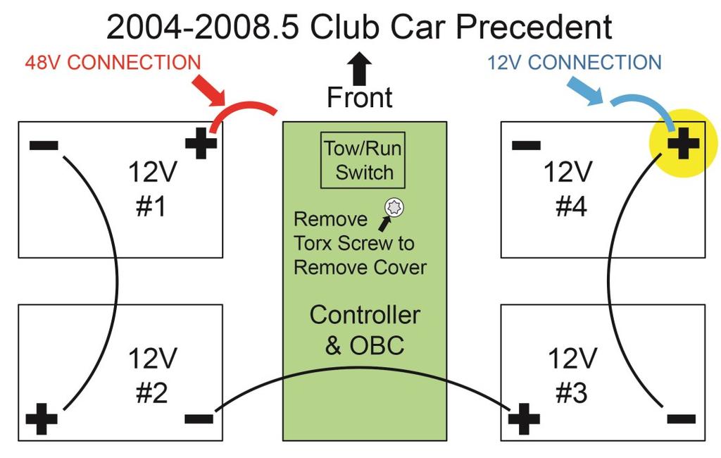
10 3. Install the headlight bumper using the Original Bumper Mounting Hardware. 4. Reinstall the dash panel using the Original Hardware. Taillight Installation 1. Connect the taillights to the wire harness leads that were pulled through the holes in the rear body. 2. Test fit each taillight. They should rest on the underbody and align with the edge of the bagwell. NOTE: Do not expose the double sided tape until the lights are functioning and have been test fitted. 3. Clean the mounting surface with rubbing alcohol. If the taillights fit properly, remove the paper on the double sided tape and mount the taillights on the rear body. 4. Use the Included Screws to further secure the taillights. Power Connections NOTE: Complete this section once all lights and optional accessories have been installed. The following diagrams show the batteries in factory configurations. Each configuration may vary. Test all batteries with a voltage meter prior to installation to determine the output voltage. CAUTION: This light kit is designed to operate at a DC voltage range of 12-48V. Please be advised that add-on accessories for this light kit may not be rated for any voltage over 12V DC and can be damaged if installed at a higher voltage. A voltage reducer must be used with 12V add-on accessories to avoid damage. 1. Verify the cart is in the TOW position (if equipped) and the key is OFF. 2. Verify any exposed wires and the push-pull switch are not touching the frame or any metal parts on the cart. Page 10
11 Electric Carts Refer to diagram on Page 12 titled Club Car Precedent. 2. Remove the controller/obc cover (shown in green). Retain hardware. 3. Connect the longer side of the fuse harness to the desired positive connection. 4. Under the cover, locate the single 12 gauge blue wire with a female connector on the main harness and connect it to the shorter side of the fuse harness. 5. Secure loose wires with cable ties. Reinstall cover with the Original Hardware. Electric Carts with 12V Batteries 1. Refer to diagram on Page 12 titled Club Car Precedent with 12V Batteries. 2. Connect the blue positive lead on the LGT-396 to the desired positive connection. If the factory cables have been replaced, connect the lead with a ring terminal. 3. Connect the black ground lead on the LGT-396 to the ground wire behind battery #3. The ground will be a 12 ga. black wire with a yellow connector. 4. Secure any loose wires with cable ties. Electric Carts with 8V Batteries NOTE: For 12V output, this battery configuration requires the installation of a voltage reducer (i.e. VOLT-0011) to reduce the voltage from 16V to 12V. 1. Refer to diagram on Page 12 titled Club Car Precedent with 8V Batteries. 2. Connect the blue positive lead on the LGT-396 to the desired positive connection. If the factory cables have been replaced, connect the lead with a ring terminal. 3. Connect the black ground lead on the LGT-396 to the ground wire behind battery #4. The ground will be a 12 ga. black wire with a yellow connector. 4. Secure any loose wires with cable ties. Page 11
12 Page 12
 wire on the fuse harness to the 12 gauge blue wire coming off")


13 Gas Carts 1. Remove the extension lead from the fuse harness. Discard. 2. Connect (1) wire on the fuse harness to the 12 gauge blue wire coming off of the solenoid. 3. Connect the second wire on the fuse harness to the 12 gauge wire coming out of the main harness loom near the solenoid. 4. Secure all loose wires with wire ties. Turn Signal Assemblies LGT-107A LGT-T1 LGT-T2 LGT-T3 NOTE: If installing a steering column cover, do so before installing the turn signal. 1. Mount the turn signal assembly in a convenient location on the steering column using the included collar and one of the included rubber inserts that best fits the diameter of the steering column. 2. Remove the jumper harness from the 9-pin turn signal connector. 3. Connect the 9-pin connector on the turn signal switch to the 9-pin connector on the LGT-696. If installing a LGT-T3 turn signal, connect the bullet connector on Page 13


 1.")
14 the turn signal harness to the bullet connector on the LGT-696 to enable the low beam function. Connect the flasher relay to the turn signal switch harness. 4. If installing the LGT-T3 turn signal, remove the push-pull switch from the 4-pin connector on the LGT-696 and replace it with the LGT-590 relay harness. Push-Pull Switch LGT Measure from the bottom of the turn signal to the dash. Using a utility knife, saw or tin snips, cut the LGT-107A (universal turn signal switch wire cover) to the measured length and sand rough edges. 6. Snap the cover around the turn signal wires and the steering column. Secure any loose wires behind the dash. Horns Horn w/ Horn Button Horn Horn Only (For Use with LGT-T2 and LGT-T3 Turn Signals) 1. Connect the (2) spade connectors on the light bar wire harness to the back of the horn on either terminal. 2. Mount the horn to the chassis using the Bolt next to the driver side upper shock mount. The horn should face away from the cart and its passengers. Page 14
.")
15 Horn with Horn Button (For use alone or with LGT-T1 Turn Signal) 1. Install the horn following Steps 1-2 on Page Locate a convenient location on the floor mat to mount the horn button. Make sure to avoid clearance issues with the brake pedal, cup holder and side trim. 3. At the top of the location, drill an 1/8 hole through the mat only (red arrow below). Do not drill through the underbody. 4. Thread the horn button s wire through the hole. Pull the wire through the hole until the horn meets the mat. 5. Place the horn decal over the button making sure it is even and the button is centered. Mark the (4) mounting holes. Remove button and decal. Drill the (4) marked locations with a 3/16 drill bit. Drill through the mat only. 6. Rethread the horn button through the hole, behind the mat and into the dash area. Place the decal back over the button. 7. Mount the decal using the Included Rivets. 8. Locate the covered horn connectors on the LGT-696. Carefully remove the cover with a utility knife. 9. Crimp the horn button wires into the butt connectors. The wires can go to either connector. 10. Route the excess wires behind the mat and into the dash area. Page 15


 at the marked location. 2. Insert the outlet through the protective cap and into the mounting area.")

16 12 Volt Receptacle and Dual USB Outlets ACC-0058 ACC-0097 CAUTION: 12V Outlets are designed for 12V operation ONLY. Operating at a voltage higher than 12V will damage accessories plugged into the outlet. 1. Find a convenient location on the dash or center compartment to mount the 12V receptacle and/or USB outlet. 2. Mark the center of the mounting location with a marking device. ACC Volt Outlet 1. Drill a 1 hole at the marked location. 2. Insert the 12V receptacle into the hole and mount it with the Included Hardware. 3. Connect the +/- 12V outlet leads on the light kit harness to the +/- 12V terminals on the back of the ACC ACC-0097 Dual USB Outlet 1. Drill a 1-1/8 hole (maximum size) at the marked location. 2. Insert the outlet through the protective cap and into the mounting area. Secure it with the retaining nut. Mount the flat panel cover over the outlet (not required) using the Included Screws. 3. Connect the +/- 12V outlet leads on the light kit harness to the +/- 12V terminals on the back of the ACC NOTE: A fuse holder (ACC-0019) and 15A fuse (ACC-0021) are recommended if direct connecting the USB ports to a 12V battery or voltage reducer. Page 16
, key is OFF and wheel is chocked. 2.")


 3/16 holes through the")

17 Brake Light Switches LGT-B1 LGT-B4 LGT-B9 All Brake Switches 1. Verify cart is in TOW position (if equipped), key is OFF and wheel is chocked. 2. If installing a brake switch without a turn signal, switch the (2) 2-pin male connectors on the jumper harness located on the turn signal connector. Leave the jumper on the harness. LGT-B1 (LGT-138) Brake Pad Light Switch, Universal Fit 1. Lock the brake pedal and center the brake pad on the lower portion of the brake pedal assembly. 2. If mounting the switch using the Included Screws, fasten the pad directly to the pedal. If mounting the switch using the Included Rivets, mark the hole locations and drill (6) 3/16 holes through the pedal. Mount the pad with the rivets. 3. With the brake pedal in PARK, run the wire from the pad down the left side of the pedal and into the pedal compartment. Keep the wire close to the driver side so it does not get pinched. 4. Drill (2) small holes in the pedal compartment close to the driver side (red arrow). Secure the LGT-138 wire out of the way with a cable tie. Brake Leads From LGT-396 From LGT-138 Page 17

18 5. Connect the brake pad lead to the LGT-150 sub-harness. Connect the LGT-150 to the brake leads from the bucket harness (LGT-396 or OE harness). Use cable ties to secure loose wires away from any moving parts. NOTE: Black ground wire is not used with the LGT-B1. The ground wire is only used with the time delay. X LGT-138 LGT-150 LGT Reinstall pedal group access panel, floor mat, lower body trim and receptacle cover using the Original Hardware. LGT-B4 (LGT-644) Linkage Activated Brake Switch with Time Delay 1. Loosen the front most nut on the brake rod. 2. Slide the small brake switch bracket upward, between the nut and rod. Tighten the nut. Disengage the brake pedal. Brake Pedal 3. Mount the brake switch towards the rear of the pedal compartment with the included Self-Tapping Screws. Position the switch so the spring is tight but not pulling the plunger (red arrow, Page 19). The plunger should move to activate the switch when the brake pedal is engaged. Unscrew the rear portion of the switch if needed for clearance. Page 18
 as shown in the diagram below: 6.")
19 4. Run the brake switch wires under the brake rod towards the passenger side of the cart. Plunger 5. Connect the brake switch to the time delay and the bucket harness (OE or LGT-396) as shown in the diagram below: 6. Secure the time delay, LGT-142, to the right side of the pedal compartment with a selftapping screw or cable ties (red arrow). Brake Leads From LGT-396 Page 19

20 7. Use cable ties to secure loose wires away from any moving parts. 8. Reinstall pedal group access panel, floor mat, lower body trim and receptacle cover using the Original Hardware. LGT-B9 Brake Pad Light Switch, OE Fit 1. Remove the OE brake pad by gently pulling it away from the pedal. NOTE: If saving the OE brake pad for future use, use caution not to tear the rubber alignment pins. 2. Reinstall the new brake pad by fitting it over the plate where the OE brake pad was removed. Page 20


21 3. With the brake pedal in PARK, run the wire from the pad down the left side of the pedal and into the pedal compartment. Keep the wire close to the driver side so it does not get pinched. 4. Drill (2) small holes in the pedal compartment close to the driver side (red arrow). Secure the LGT-B9 wire out of the way with a cable tie. Brake Leads From LGT-396 From LGT-B9 5. Connect the brake pad to the brake leads from the bucket harness (LGT-396 or OE harness). Use cable ties to secure loose wires away from any moving parts. NOTE: Black ground wire is not used with the LGT-B9. X Page 21 LGT-B9 LGT-396

22 6. Reinstall pedal group access panel, floor mat, lower body trim and receptacle cover using the Original Hardware. Your Precedent Light Kit is now complete. Please enjoy safely! Scan QR code or use the link below to view the installation video. Page 22
23 Page 23 NOTES

24 Page 24
LGT-312L E-Z-Go TXT Light Bar Bumper Kit Installation Instructions
 LGT-312L E-Z-Go TXT 2014+ Light Bar Bumper Kit Installation Instructions Caution: Please read through the instructions carefully. Before starting this project, remove the system s positive and negative
Adjustable Light Kits E-Z-Go TXT All Models Installation Instructions
 Adjustable Light Kits E-Z-Go TXT All Models 1996-2013 Installation Instructions Caution: Please read through the instructions carefully. Before starting this project, remove the system s positive and negative
LGT-311L Bumper LED Light Kit EZ-Go RXV Installation Instructions
 LGT-311L Bumper LED Light Kit EZ-Go RXV Installation Instructions Caution: Please read through the instructions carefully. Before starting this project, remove the system s positive and negative connections
Bucket Harness. Installation Instructions. for Electric Club Car Precedent
 Bucket Harness for Electric Club Car Precedent Installation Instructions Electric Club Car Precedents manufactured after January 1, 2008 require an additional harness to allow the installation of light
Not Included. Rear Half Harness
 Basic Light Kit 60102 Caution! Wear appropriate eye protection! Disconnect the battery or batteries. Place run/tow switch in tow position before disconnecting the batteries on models using that feature.
LIFT-304 (3 ) and LIFT-104 (6 ) Drop Spindle Lift Kits Yamaha G22, Gas or Electric Installation Instructions
 and LIFT-104 (6 ) Drop Spindle Lift Kits Yamaha G22, Gas or Electric Installation Instructions") LIFT-304 (3 ) and LIFT-104 (6 ) Drop Spindle Lift Kits Yamaha G22, Gas or Electric Installation Instructions LIFT-304 LIFT-104 Contents of LIFT-304/104 Yamaha G22 Lift Kit: a (1 ea.) Passenger Side Spindle
LIFT-304 (3 ) and LIFT-104 (6 ) Drop Spindle Lift Kits Yamaha G22, Gas or Electric Installation Instructions LIFT-304 LIFT-104 Contents of LIFT-304/104 Yamaha G22 Lift Kit: a (1 ea.) Passenger Side Spindle
LIFT Standard A-Arm Lift Kit Club Car Precedent Installation Instructions
 LIFT-563 6 Standard A-Arm Lift Kit Club Car Precedent Installation Instructions Contents of LIFT-563 Club Car Precedent Lift Kit: a (1 ea.) Front Suspension b (1 ea.) Driver Side Upper A-Arm c (1 ea.)
LIFT Drop Spindle Lift Kit E-Z-Go RXV Gas or Electric Installation Instructions
 LIFT-107 6 Drop Spindle Lift Kit E-Z-Go RXV Gas or Electric Installation Instructions Contents of LIFT-107 E-Z-Go RXV Drop Spindle Lift Kit: a (1 ea.) Driver Side Spindle b (1 ea.) Passenger Side Spindle
LIFT-507 BMF Lift Kit E-Z-Go RXV Gas or Electric Installation Instructions
 LIFT-507 BMF Lift Kit E-Z-Go RXV Gas or Electric Installation Instructions Contents of LIFT-507 E-Z-Go RXV BMF Lift Kit: a (1 ea.) BMF A-Arm Assembly b (1 ea.) Driver Side Shock Tower c (1 ea.) Passenger
Turn Signal / Horn Kit PN 7101 by All years Polaris RZR 1000 and RZR 900, 900-4, 900 trail, 900S and 900XC STOP - THIS KIT IS DESIGNED
 All years Polaris RZR 1000 and 1000-4 2015 RZR 900, 900-4, 900 trail, 900S and 900XC STOP - THIS KIT IS DESIGNED SPECIFICALLY FOR ALL YEAR AND MODEL POLARIS RZR 1000 AND 1000-4. ALSO THE 2015 POLARIS RZR
LIFT-504. BMF Lift Kit. Yamaha G22 Gas or Electric. Installation Instructions
 LIFT-504 BMF Lift Kit Yamaha G22 Gas or Electric Installation Instructions Contents of LIFT-504 Yamaha G22 BMF Lift Kit: a (1 ea.) BMF A-Arm Assembly b (1 ea.) Driver Side Shock Tower c (1 ea.) Passenger
WOC & WOC Top & Back Installation Instructions
 Shown with optional Sun Roof WOC-900500-2 & WOC-900501-2 Top & Back Installation Instructions Install Order! Heater Door System Wiper on to Windshield Windshield Rear Panel Top Panel Tools needed: 5/16
Tail lights. Headlights
 Revised December 2014 02-017 Light Kit will fit Yamaha G-Series* installation instructions included: tools needed: 2 Headlights 2 Tail Lights Wiring Harness Screws Straps Hazard Switch Phillips Head Screw
SCION FRS FOG LIGHTS. Part Number: SFR-313
 Part Number: SFR-313 Kit Contents Item # Quantity Reqd. Description 1 2 Light Housings 2 2 Fog Light bezels 3 1 Harness bag 4 1 User s card 5 1 Switch 6 1 Fuse jumper Hardware Bag Contents Item # Quantity
Installation Instructions Z-Gate Shifter
 Installation Instructions Z-Gate Shifter Part Number 80681 1998, 2001 by B&M Racing and Performance Products The B&M Z-Gate shifter can be used in vehicles equipped with most popular three speed automatic
Z-Gate Universal Shifter
 Installation Instructions Z-Gate Universal Shifter Fits: GM, Ford, Lincoln and Chrysler Transmissions See Application Guide for Specific Applications Part #80681 Rev 06/01/2018 WORK SAFELY! For maximum
TOYOTA PRIUS FOG LIGHT (Halogen or LED)
") Part Number: TPR-413 / TPR-813 Kit Contents Item # Quantity Reqd. Description 1 2 Fog Lamps 2 1 Lower Grill 3 1 Switch Assembly 4 1 Fog Light Operation guide 5 1 Harness Bag Hardware Bag Contents Item
Part Number: TPR-413 / TPR-813 Kit Contents Item # Quantity Reqd. Description 1 2 Fog Lamps 2 1 Lower Grill 3 1 Switch Assembly 4 1 Fog Light Operation guide 5 1 Harness Bag Hardware Bag Contents Item
INSTALLATION INSTRUCTIONS
 INSTALLATION INSTRUCTIONS Accessory Application Publications No. AII 22903-22963 ODYSSEY Issue Date MAY 2002 PARTS LIST Subwoofer Kit: P/N 08A39-EP7-100 Subwoofer 2 Cushion tapes 8 Wire ties (1 not used)
INSTALLATION INSTRUCTIONS
 Rear Vision System Aftermarket and Factory 5.0, 8.4 and 6.1 MyGig Touch Screen Display (Factory Display requires Chrysler/Dodge dealer to activate) 2009 Current* Dodge Ram (Kit part number 1009-6503) *NOTE:
TOYOTA RAV4/HV INTERIOR LIGHT KIT Preparation
 Preparation Part Number: PT413-42130 Kit Contents Item # Quantity Reqd. Description 1 1 Wire Harness 2 3 Hardware Bag Contents Item # Quantity Reqd. Description 1 20 Cable Tie 2 2 Scotchlok 3 2 Foam Pad
INSTALLATION INSTRUCTIONS
 INSTALLATION INSTRUCTIONS Accessory S P/N 08V67-SJC-101 Application 2012 RIDGELINE Publications No. AII 12006 Issue Date NOV 2011 PARTS LIST Back-up sensor harness 3 Wire ties with small clips (2 Not used)
2016 HONDA 1000 Pioneer PN 3102 Turn signal / horn kit rev nc
 2016 Honda 1000 Pioneer STOP - THIS KIT IS DESIGNED SPECIFICALLY FOR 2016 HONDA 1000 PIONEER IF YOUR MACHINE IS NOT THIS MODEL DO NOT PROCEED. THIS KIT DOES NOT WORK ON THE PIONEER 500 nor 700 S. Contact
INSTALLATION INSTRUCTIONS
 INSTALLATION INSTRUCTIONS Accessory S P/N 08V67-SJC-101 Application 2010 RIDGELINE Publications No. AII 42117 Issue Date AUG 2009 PARTS LIST Back-up sensor harness 3 Wire ties with small clip (2 Not used)
MKVI Jetta Fog Light Kit
 MKVI Jetta Fog Light Kit Part Number VW Jetta Fog Light Installation This tutorial is provided as a courtesy by ECS Tuning. Proper service and repair procedures are vital to the safe, reliable operation
Club Car 1510 to Curtis 1268 Conversion
 Club Car 1510 to Curtis 1268 Conversion Installation Instructions 62-12685501CKI Rev. 05 7/18/14 Page 1 of 7 1510 to Curtis 1268 Conversion Installation Instructions Before you start turn Tow/Run switch
Part Number: TCA-712SE
 Date: 09.04.2013 TOYOTA CAMRY SE 2012-14 LED DRL Part Number: TCA-712SE Kit Contents Item # Quantity Reqd. Description 1 2 DRL s bezels w/led DRL 2 1 Driver Box 3 1 Harness bag 4 1 User s card 5 1 Cushion
LED Fog Light. Conflicts Note: 1832, 1852, 1856, 1872, General Applicability Fits Models
 LED Fog Light Year & Model Part Number 2017 Corolla TCO-817 Conflicts Note: 1832, 1852, 1856, 1872, 1874 General Applicability Fits Models 1863 1866 1864 1865 Additional Items Required For Installation
CONTENTS TOOLS REQUIRED:
 CONTENTS 1EA. FIVE CHANNEL AMPLIFIER P/N MPDSP033AA 1EA. AMPLIFIER BRACKET P/N RM11JK41 1EA. POWER HARNESS P/N RH41JKP 1EA. OVERLAY HARNESS P/N RH41JK 1EA. FUSE 30 AMP P/N RFUSE30 6EA. WIRE TIE P/N RFZIP6
INSTALLATION INSTRUCTIONS
 9002-6513 Rear Vision System W/ Zoom Aftermarket and Factory 8.4 Touch Screen Display (Factory Display requires Chrysler/Dodge dealer to activate) 2009 2012 RAM (Part B) 2013 Current RAM (Part A) NOTE:
6945 (12v) 6944 (24V) installation instructions
 6944 (24V) installation instructions") 6945 (12v) 6944 (24V) installation instructions included: tools needed: Cordless drill Breezeeasy Fan Mounting brackets 1/4 Drill Bit 10mm Socket Hardware Pack 10mm Wrench Fuse Assembly Wire Stripper Crimper
6945 (12v) 6944 (24V) installation instructions included: tools needed: Cordless drill Breezeeasy Fan Mounting brackets 1/4 Drill Bit 10mm Socket Hardware Pack 10mm Wrench Fuse Assembly Wire Stripper Crimper
INSTALLATION INSTRUCTIONS
 INSTALLATION INSTRUCTIONS Accessory Application Publications No. S 1998 CIVIC 2/3/4-DOOR All 18767 Issue Date SEP 1997 PARTS LIST Fog Light Kit: P/N 08V31-S01-100 Right fog light (marked R ) Fuse label
Ram 1500 Crew Cab A Ram 2500/3500 Crew Cab A
 I N S T A L L A T I O N G U I D E APPLICATION AMP Part # Ram 1500 Crew Cab 2013-2015 77138-01A Ram 2500/3500 Crew Cab 2013-2015 77138-01A Note:The application works only on the Crew Cab model Vehicles.
INSTALLATION INSTRUCTIONS
 INSTALLATION INSTRUCTIONS Accessory HITCH Application 2012 CROSSTOUR Publications No. AII 46198 Issue Date JULY 2011 PARTS LIST Trailer Hitch Kit P/N 08L92-TP6-101 Upper spacer A (5 mm) (Some are not used.)
LHT CC LIGHT WIRING Instructions for Club Car DS Models
 LHT CC5 1001 LIGHT WIRING Instructions for Club Car DS Models This Light Kit includes: (1) Main Wire Harness with Dual InLine Fuses (1) Headlight Switch (1) Left hand headlight (1) Right hand headlight
FOG LAMPS INSTALL KIT
 FOG LAMPS INSTALL KIT PT CRUISER INSTALLATION INSTRUCTIONS Read entire instructions thoroughly before starting. For proper aiming of fog lamps, follow procedures in the service manual. NOTES: Left and
INSTALLATION INSTRUCTIONS
 Rear Vision System Tailgate Emblem Camera Mirror Display 2009-Current Ford F-150 and 2010-Current Super Duty (Kit part number 1008-9527) Kit Contents: Mirror Tailgate Emblem Mount with Camera Interior
Please read thoroughly before starting installation and check that kit contents are complete.
 Rear Vision System Mirror Display 2013-Current Ram (Kit part number 1009-9518) Please read thoroughly before starting installation and check that kit contents are complete. Items Included in the Kit: Rear
RFB MK6 Jetta Fog Light Kit Wiles Rd.Coral Springs, FL
 What s Included: Tools Required: (2) Fog Lights (2) Front Grills Wire Harness Headlight Switch Hardware Kit T25 Torx Wire Cutters 10mm Socket and Rachet Headlight Switch Composite Wedge Tool 01 1. Remove
INSTALLATION INSTRUCTIONS
 Rear Vision System Liftgate Emblem Camera Mirror Display 2009-2012 Ford Flex (Kit part number 1008-9527) Kit Contents: Mirror Liftgate Emblem Mount with Camera Interior (shorter) Harness Chassis (longer)
PRODUCT INSTRUCTIONS
 PRODUCT INSTRUCTIONS Thank you for purchasing genuine Design Engineering, Inc. products. Be sure to always wear the proper safety equipment when installing any DEI product. Design Engineering Inc. WILL
GENUINE ACCESSORIES INSTALLATION INSTRUCTIONS
 GENUINE ACCESSORIES INSTALLATION INSTRUCTIONS PART NUMBERS: APPLICABLE MODELS: 0000-89-G14A (PORT) Electrochromic Mirror Kit w/ Compass/Temp/HomeLink 2004 Mazda 3 0000-8C-G14A (PDC) KIT CONTENTS: ITEM
INSTALLATION INSTRUCTIONS
 INSTALLATION INSTRUCTIONS Accessory Accessory Hands Free Link Application 2008 ACCORD 2 AND 4-DOOR Publications No. AII 38281 Issue Date NOV 2007 PARTS LIST Attachment Kit P/N 08E02-TA0-100 trim retainer
SCION tc 2014 FOG LIGHT KIT
 Part #: PT413-21140 Conflicts: P/N PTR11-21100 Lowering Springs (CA only) Kit Contents: Wire Ties Self-Tapping Screws Switch Relay Fog Light Bezel, Left and Right Side Wire Harness Fog Lamp, Left and Right
INSTALLATION INSTRUCTIONS
 INSTALLATION INSTRUCTIONS Accessory Application Publications No. AII 26031 2004 ODYSSEY Issue Date AUG 2003 NOTE: You cannot install the subwoofer in a vehicle equipped with both an under seat Navigation
ACD-PRO Install in 2008 EvoX
 Turning in a counter clockwise direction, unscrew ift knob ACD-PRO Install in 2008 EvoX Slide back and remove the floor console panel assembly Pull up to remove the center console tray Disconnect the plug
Conflicts - Fog Lights
 TOYOTA CAMRY 2013 - BLACKOUT LED DRL Part Number: 00016-32270 Accessory Code: LDBO10 Conflicts - Fog Lights Kit Contents Item # Quantity Reqd. Description 1 2 DRL Housing 2 2 DRL s bezels 3 1 Driver Box
CAMRY STRIP LED DRL TOYOTA Part Number: Accessory Code: LDRS10. PIO / DIO Rev. A 02/26/13. Doc
 Doc. 02.126.00 TOYOTA CAMRY PIO / DIO Rev. A 2013-02/26/13 STRIP LED DRL Part Number: 00016-32280 Accessory Code: LDRS10 Conflicts - Only works on Camry SE Kit Contents Item # Quantity Reqd. Description
YARIS 4-DOOR 2007 INTERIOR LIGHT UPGRADE
 Document # 3999 4/26/06 4-DOOR 2007 INTERIOR LIGHT UPGRADE Preparation Part Number: 00016-52060 Code: IL1 Kit Contents Item # Quantity Reqd. Description 1 1 12 Light Guide 2 1 7 Light Guide 3 1 Hardware
BX8848 Installation Instructions 4 Diode Wiring Kit For Motorhomes With Red Tail Lights
 For Motorhomes With Red Tail Lights WARNG: Incorrect wiring may result in blown fuses, damaged wiring, fire, or bodily injury. Blue Ox recommends installation of this kit by a trained professional. Blue
Toyota 4RUNNER With/MR Overhead Video
 Toyota 4RUNNER With/MR 2010-10.2 Overhead Video Part Number: 00016-00110; Fit Kit-00110-14, Beige 00016-00120; Fit Kit-00120-14, Gray Accessory Code: ED7 Conflicts: Vehicles without a sunroof Kit Contents:
TOYOTA RAV FOG LIGHT KIT Preparation
 Preparation Part Number: PT413-42163 Kit Contents Item # Quantity Reqd. Description 1 7 7 Wire Tie 2 4 #10-16 Cross Pan-Washer Head Screws 3 1 Switch 4 1 Relay 5 1 LH Fog Light Bezel 6 1 RH Fog Light Bezel
INSTALLATION INSTRUCTIONS
 Rear Vision System Tailgate Emblem Camera Aftermarket Display 2009-Current Ford F-150 and 2010-Current Super Duty (Kit part number 1008-6509) Kit Contents: Tailgate Emblem Mount with Camera Chassis Harness
Part Number: T4R-2N1. Hardware Bag Contents. General Applicability Models with factory fog light
 11/10/16 TOYOTA CAMRY 2012-2014 2 in 1 LED UPGRADE KIT Part Number: T4R-2N1 Kit Contents Item # Quantity Reqd. Description 1 2 DRL + Fog Light Housing 2 1 Driver Box 3 1 Harness bag 4 1 User s card 5 1
Installation MKIV Headlight Housings with Fog Lamps (Procedures apply to both MKIV Jetta and Golf)
") Page 1 This tutorial is provided as a courtesy by ECS Tuning. Service Procedure Installation Proper service and repair procedures are vital to the safe, reliable operation of all motor vehicles as well
Page 1 This tutorial is provided as a courtesy by ECS Tuning. Service Procedure Installation Proper service and repair procedures are vital to the safe, reliable operation of all motor vehicles as well
INSTALLATION MANUAL. Level of Difficulty. Parts List. Product Image. Tools Required. Notes and Maintenance. Torque Specifications.
 INSTALLATION MANUAL Parts List 1 Bull bar 2 Upper frame mounting bracket 1 Driver / left lower frame mounting bracket 1 Passenger / right lower frame mounting bracket 2 Button head bolt, 6mm 4 Flat washer,
Accessory Kit Estimated Fitting Time: 120 Minutes (Prado) Estimated Fitting Time: 140 Minutes (Kluger)
 Estimated Fitting Time: 140 Minutes (Kluger)") Tow-Pro Wiring Kit - Toyota Kluger / Prado Accessory Kit Estimated Fitting Time: 0 Minutes (Prado) Estimated Fitting Time: 0 Minutes (Kluger) FI99 Page 0 of Issue: Date: 0/0/0 0 General Notes Read through
Tow-Pro Wiring Kit - Toyota Kluger / Prado Accessory Kit Estimated Fitting Time: 0 Minutes (Prado) Estimated Fitting Time: 0 Minutes (Kluger) FI99 Page 0 of Issue: Date: 0/0/0 0 General Notes Read through
TOYOTA COROLLA L, LE FOG LIGHT (Halogen and LED) Part Number: TCO-314 / TCO-814
 Part Number: TCO-314 / TCO-814") TOYOTA COROLLA L, LE 2014-16 FOG LIGHT (Halogen and LED) Part Number: TCO-314 / TCO-814 Kit Contents Item # Quantity Reqd. Description 1 2 Light Housings 2 2 Fog Light bezels 3 1 Switch Assembly 4 1 Fog
TOYOTA COROLLA L, LE 2014-16 FOG LIGHT (Halogen and LED) Part Number: TCO-314 / TCO-814 Kit Contents Item # Quantity Reqd. Description 1 2 Light Housings 2 2 Fog Light bezels 3 1 Switch Assembly 4 1 Fog
INSTALLATION INSTRUCTIONS
 INSTALLATION INSTRUCTIONS Accessory Application Publications No. P/N 08V31-SDN-100 2004 ACCORD 2-DOOR AII 25735 Issue Date SEP 2003 NOTE: The outside temperature gauge can not be installed in a vehicle
WPS-104 Heater Installation Instructions For 500EFI, 700 XP, & Crew Applications
 WPS-104 Heater Installation Instructions For 500EFI, 700 XP, & Crew Applications ORDER OF INSTALLATION FOR A COMPLETE ENCLOSURE OF A RANGERWARE WPS (Weather Protection System) IS AS FOLLOWS: 1. Heater
Part Number: TAV-713 TOYOTA AVALON LED DRL
 Part Number: TAV-713 Kit Contents Item # Quantity Reqd. Description 1 2 DRL s bezels w/led DRL 2 1 Driver Box 3 1 Harness bag 4 1 User s card 5 1 Cushion pad 6 1 Switch 7 2 Drill Jigs Hardware Bag Contents
INSTALLATION INSTRUCTIONS
 Accessory Application Publications No. INSTALLATION INSTRUCTIONS S (LX, EX) CIVIC 2- AND 4- DOOR AII 25449 Issue Date SEP 2003 NOTE: Fog Lights cannot be installed if the vehicle is equipped with an optional
SCION xb HEADREST DVD RSE Section I Installation Preparation. Part Number: PT
 Section I Installation Preparation Part Number: PT900-52080 Kit Contents Item # Quantity Reqd. Description 1 2 DVD Headrest Unit 2 2 Headrest Extension Cables 3 1 Audio Interface Module 4 1 Audio Interface
Installation instruction do88 Intercooler for SAAB 9-3 1,9 TTiD
 Installation instruction do88 Intercooler for SAAB 9-3 1,9 TTiD This instruction shows how to replace the OEM intercooler with this performance intercooler. At this type of installation we always recommend
LEXUS GS 350/450h ILLUMINATED DOOR SILLS Preparation
 Preparation Part Number: PT922-30120 (GS350) PT922-30130 (GS450h) NOTE: Part number of this accessory may not be the same as the part number shown. Kit Contents Item # Quantity Req'd. Description 1 1 Illuminated
Conflicts: Vehicles with a sunroof
 Toyota 4Runner Non/MR 2010-10.2 Overhead Video Part Number: 00016-00110; Fit Kit -00110-15, Beige 00016-00120; Fit Kit -00120-15, Gray Accessory Code: ED6 Conflicts: Vehicles with a sunroof Kit Contents:
INSTALLATION INSTRUCTIONS
 INSTALLATION INSTRUCTIONS Accessory Application 2008 ACCORD 2-DOOR Publications No. AII 37561-38377 Issue Date NOV 2007 PARTS LIST Control unit bracket (L4) Back-up Sensor Attachment Kit P/N 08V67-TE0-100A
INSTALLATION INSTRUCTIONS
 INSTALLATION INSTRUCTIONS Accessory ACCESSORY HANDSFREELINK Application 2010 ACCORD 2 AND 4-DOOR Publications No. AII 42231 Issue Date AUG 2009 PARTS LIST HFL retainer HFL Attachment Kit P/N 08E02-TA0-100
SCION FR-S FOG LIGHTS
 Part #: PT413-18130 Conflicts: Lowering Springs PTR07-18130-LL (California only) Kit Contents: For Anniversary Edition, Monogram & RS 2.0 vehicles, additional parts need to be ordered (PT413-18130-LL)
INSTALLATION INSTRUCTIONS
 Accessory Application Publications No. INSTALLATION INSTRUCTIONS S (DX, HX, VP) 2005 CIVIC 2- AND 4- DOOR AII 27865-30866 Issue Date SEP 2005 NOTE: Fog Lights cannot be installed if the vehicle is equipped
Fitting Instructions
 Reverse Park Assist Suitable for: Nissan Navara Kit Part No: 5466XX NP00 Tow-Pro Wiring Kit Fitting Instructions Accessory Kit Estimated Fitting Time: 0 Minutes FI98 Page 0 of 5 General Notes Read through
Depress each tab as you pull the bezel off. The bezels are tight. L.H. shown.
 2013-2014 Ford Mustang V6 & Boss 302 Lower Valance Fog Light Kit Parts List: Quantity: Tool List: Fog light & bulb with bracket 2 Flat head & Phillips screwdriver Black bezels 2 Ratchet & Socket set OR
LEXUS RC 350/RC-F ILLUMINATED DOOR SILLS Preparation
 Preparation Part Number: PT944-24150 Kit Contents Item # Quantity Reqd. Description 1 2 Inner LED Scuff 2 2 Outer Scuff 3 1 Hardware Bag Hardware Bag Contents Item # Quantity Reqd. Description 1 15 20
Wolverine Turn Signal / Horn Kit 2102
 All years Yamaha Wolverine STOP - THIS KIT IS DESIGNED SPECIFICALLY FOR ALL YEAR AND MODELS YAMAHA WOLVERINE. IF YOUR MACHINE IS NOT ONE OF THESE MODELS DO NOT PROCEED. Contact Ryco Motorsports or your
INSTALLATION INSTRUCTIONS
 INSTALLATION INSTRUCTIONS Accessory Accessory Hands Free Link Application 2009 ACCORD 2 AND 4-DOOR Publications No. AII 40055 Issue Date JULY 2008 PARTS LIST HFL Attachment Kit P/N 08E02-TA0-100 HFL trim
IT IS IMPORTANT THAT YOU OBTAIN THE CORRECT INFORMATION FOR YOUR VEHICLE, OR DAMAGE TO THE WIRING SYSTEM COULD OCCUR.
 Instructions for Universal Harness PRINT THESE INSTUCTIONS Gentex Mirror Installation Instructions Provided by www.rearviewautomirrors.com These instructions have been prepared to provide you with details
SAFETY THIS PRODUCT IS FOR OFFROAD USE ONLY. ALL LIABILITY FOR INSTALLATION AND USE RESTS WITH THE OWNER.
 SAFETY Your safety and the safety of others is very important. In order to help you make informed decisions about safety, we have provided installation instructions and other information. These instructions
General Applicability Note: Recommended Tools. Personal & Vehicle Protection Safety Goggles Seat Covers Floor Covers Special Tools. Installation Tools
 TOYOTA HIGHLANDER/HIGHLANDER HV 2008- Preparation Part #: PT923-00111 Conflicts: JBL Audio, Factory Navigation NOTE: Part number of this accessory may not be the same as the part number shown. Kit Contents:
Rear Vision System Liftgate Emblem Camera for Aftermarket Display Ford Flex (Kit part number )
") Rear Vision System Liftgate Emblem Camera for Aftermarket Display 2009-2012 Ford Flex (Kit part number 1008-6509) Kit Contents: Liftgate Emblem Mount with Camera Chassis Harness with RCA (Note: In some
Rear Vision System Liftgate Emblem Camera for Aftermarket Display 2009-2012 Ford Flex (Kit part number 1008-6509) Kit Contents: Liftgate Emblem Mount with Camera Chassis Harness with RCA (Note: In some
Conflicts. TOYOTA Prius Foglights. Part Number: Accessory Code: LF1. Factory Fog Lights
 TOYOTA Prius 2011- Foglights Part Number: 00016-47401 Accessory Code: LF1 Conflicts Factory Fog Lights Item # Quantity Reqd. Description 1 2 Fog Lamps 2 2 Fog Lamp s bezels 3 1 Switch Assembly 4 1 Fog
led light Kit included: tools needed: 2 LED Headlights 2 LED Tail Lights Wiring Harness Screws Straps Rocker Switch WILL FIT CLUB CAR DS
 led light Kit WILL FIT CLUB CAR DS 02-033 included: tools needed: 2 LED Headlights 2 LED Tail Lights Wiring Harness Screws Straps Rocker Switch Phillips head screw driver Cutting Tool Sandpaper Power Drill
Classic Light Bar Mustang
 Classic Light Bar 2005-2012 Mustang Note: Read installation instructions before starting. Component List: 1 Light Bar Part #110000 1 Driver Side Bracket w/set Screw Part #115003 1 Passenger Side Bracket
INSTALLATION INSTRUCTIONS
 INSTALLATION INSTRUCTIONS Accessory Application Publications No. S CIVIC 2 AND 4-DOOR (EX, LX) AII 24188 Issue Date AUG 2002 NOTE: Fog Lights cannot be installed if the vehicle is equipped with an optional
Part Number: TCO-314 / TCO-814
 Date: 05.02.2014 TOYOTA COROLLA L, LE 2014-15 FOG LIGHT (Halogen and LED) Part Number: TCO-314 / TCO-814 Kit Contents Item # Quantity Reqd. Description 1 2 Light Housings 2 2 Fog Light bezels 3 1 Switch
PHASE 3 POWERSPORTS AUDIO KIT MAVERICK X3 CAN-AM. pg 3 Disassembly, Wire and Amplifier Plate Installation. pg 11 Dash Kit Installation
 CAN-AM MAVERICK X3 PHASE 3 POWERSPORTS AUDIO KIT pg 3 Disassembly, Wire and Amplifier Plate Installation pg 11 Dash Kit Installation pg 15 Underseat Subwoofer Installation pg 19 Dash Speaker Pods Installation
Air Conditioner for M915 A0/A1 Truck
 RD-2-4530-0 Air Conditioner for M915 A0/A1 Truck INSTALLATION INSTRUCTIONS Install refrigerant compressor per instructions provided with compressor mount kit. CAUTION: Edges of sheet metal can be sharp!
INSTALLATION INSTRUCTIONS. Rear Vision System Aftermarket Display 2009-Current Dodge Ram (Kit part number )
") Rear Vision System Aftermarket Display 2009-Current Dodge Ram (Kit part number 1009-6503) Kit Contents: Chassis Harness with RCA (Note: In some cases a RCA extension may be required to connect to your
Rear Vision System Aftermarket Display 2009-Current Dodge Ram (Kit part number 1009-6503) Kit Contents: Chassis Harness with RCA (Note: In some cases a RCA extension may be required to connect to your
INSTALLATION INSTRUCTIONS
 INSTALLATION INSTRUCTIONS Accessory Application Publications No. CIVIC AII 24171 S 2- AND 4-DOOR Issue Date (DX, HX) AUG 2002 NOTE: Fog Lights cannot be installed if the vehicle is equipped with an optional
MKVI Jetta Fog Light Kit
 MKVI Jetta Fog Light Kit Part Number VW Jetta Fog Light Installation This tutorial is provided as a courtesy by ECS Tuning. Proper service and repair procedures are vital to the safe, reliable operation
CONTENTS: TOOLS REQUIRED:
 CONTENTS: 1EA. FIVE CHANNEL AMPLIFIER/BRACKET ASSEMBLY P/N RBI77KICK37 1EA. POWER HARNESS P/N RH41PMP 1EA. OVERLAY HARNESS P/N RH41PM 3EA. NUT P/N RFM6NUT 6EA. WIRE TIE P/N RFZIP6 1EA. FUSE 30 AMP P/N
LED Fog Light. Conflicts Note: 1226, General Applicability Fits Models Additional Items Required For Installation
 LED Fog Light Year & Model Part Number Conflicts Note: 1226, 1228 2017 Prius TPR-817 General Applicability Fits Models 1221 1225 1223 1227 1224 Additional Items Required For Installation Items 1 N/A 2
Setting the World s Performance Standards
 Setting the World s Performance Standards 743 East Iona Road, Idaho Falls, ID 83401, (208) 529-0244 Fax (208) 529-9000 Forced Air Hot Air Elimination Kit (Bed Fan Kit) For 800 RZR-4 P/N 67-165 Kit Contents:
Part Number: SFR-713. Hardware Bag Contents. General Applicability All models. Conflicts - Fog Lights. Date: SCION FRS LED DRL
 Date: 01.30.2014 SCION FRS 2013-2015 LED DRL Part Number: SFR-713 Kit Contents Item # Quantity Reqd. Description 1 2 DRL s bezels w/led DRL 2 1 Driver Box 3 1 Harness bag 4 1 User s card 5 1 Switch Hardware
Installation instruction do88 Intercooler for SAAB 9-3SS/SC 4-cyl Turbo
 Installation instruction do88 Intercooler for SAAB 9-3SS/SC 4-cyl Turbo This instruction shows how to replace the OEM intercooler with this performance intercooler. 1. 4. 5. At this type of installation
Installation instruction do88 Intercooler for SAAB 9-3SS/SC 2,8 V6 Turbo
 Installation instruction do88 Intercooler for SAAB 9-3SS/SC 2,8 V6 Turbo This instruction shows how to replace the OEM intercooler with this performance intercooler. At this type of installation we always
INSTALLATION INSTRUCTIONS
 INSTALLATION INSTRUCTIONS Accessory S Application 2010 PILOT (LX ONLY) Publications No. AII 41642 Issue Date MAY 2009 PARTS LIST TOOLS AND SUPPLIES REQUIRED Fog Lights Kit P/N 08V31-SZA-100B Flat-tip screwdriver
INSTALLATION INSTRUCTIONS. Rear Vision System Aftermarket Display 2009-Current Dodge Ram (Kit part number )
") Rear Vision System Aftermarket Display 2009-Current Dodge Ram (Kit part number 1009-6503) Kit Contents: Chassis Harness with RCA Endgate Handle with Camera 1 bag containing: Wire Ties (Qty: 17) Bottle
Rear Vision System Aftermarket Display 2009-Current Dodge Ram (Kit part number 1009-6503) Kit Contents: Chassis Harness with RCA Endgate Handle with Camera 1 bag containing: Wire Ties (Qty: 17) Bottle
TOYOTA YARIS HATCHBACK INTERIOR LIGHT UPGRADE Preparation
 Preparation Part Number PTS21-52062-08 NOTE: Part number of this accessory may not be the same as the part number show Kit Contents Item # Quantity Reqd. Description 1 1 12 Light Guide 2 1 7 Light Guide
INSTALLATION INSTRUCTIONS
 INSTALLATION INSTRUCTIONS Accessory Application Publications No. SYSTEM 2005 ACCORD All 27511 (DX, LX) 2-AND 4-DOOR Issue Date AUG 2004 PARTS LIST Security System Attachment (LX): P/N 08E55-SDA-100A Unit
INSTALLATION INSTRUCTIONS
 INSTALLATION INSTRUCTIONS Accessory Application Publications No. ATTACHMENT (EX-L WITH NAVI) 2008 RIDGELINE AII 36587 Issue Date MAY 2007 PARTS LIST Attachment Kit P/N: 08B21-SJC-102 Template Rear camera
TOYOTA TACOMA FOG LIGHT (Halogen or LED)
") Part Number: TTA-312 / TTA-812 Kit Contents Item # Quantity Reqd. Description 1 2 Fog Lamps 2 1 Switch Assembly 3 1 Fog light operation guide 4 1 Harness bag Hardware Bag Contents Item # Quantity Reqd.
Part Number: TTA-312 / TTA-812 Kit Contents Item # Quantity Reqd. Description 1 2 Fog Lamps 2 1 Switch Assembly 3 1 Fog light operation guide 4 1 Harness bag Hardware Bag Contents Item # Quantity Reqd.