Electro Wizard Battery Disconnect Switch
|
|
|
- Alaina Boone
- 6 years ago
- Views:
Transcription


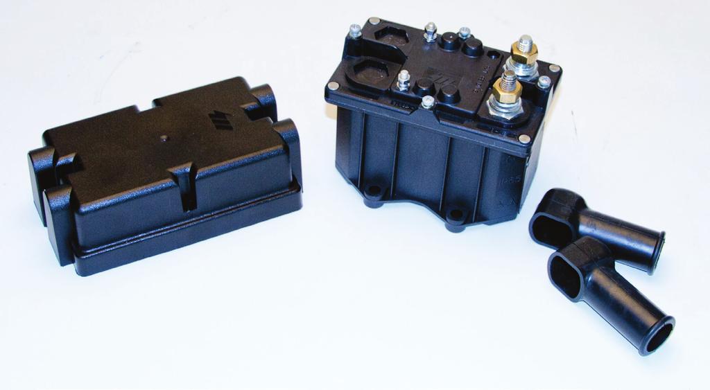

1 TM Electro Wizard Battery Disconnect Switch
2 FR1051 Mounting Diagram Positive disconnection, 12V GROUNDED SOLENOID (power supply coil negative)
3 FR1051 Technical Specifications Positive disconnection, 12V GROUNDED SOLENOID (power supply coil negative) CHARACTERISTICS FR1051 Nominal tension Max 12V Max. continuous current on main 250 A (23 C / 73.4 F) contacts Max. short time current on main 2500 A x 3 sec. contacts Recommended wire section >75mm² / sq in Protection degree IP 65 Tightening torque M10 nuts 20 Nm / 14.75ft lb Tightening torque M5 nuts 1.6 Nm / 1.18 ft lb Operating temperature range -40 C/+85 C -40 F/+185 F Contacts Silver plated copper Contact terminals M10 tin-plated brass Nuts for contacts Brass Peak current coil rated input 4.4 A Max. retaining coil 3.2 A Holding coil rated input 0.4 A FITTING INSTRUCTIONS: The battery isolator switch must be placed as close as possible to the batteries. To avoid corrosion to wires and terminals, mount in a protected location. It can be fixed to the frame according to the fitting diagram shown in the drawing, using M 8 TCEI (cylindrical head encased hexagon) screws UNI 5931: 1984, and plain washers 8,4x1.7 UNI 6592:1969. The inversion of the power supply to the coil causes serious damage to the internal diode. ELECTRICAL DIAGRAM
4 FR1051 Positive disconnection, 12V GROUNDED SOLENOID (power supply coil negative) The Flaming River FR1051 Disconnect Switch is designed to disconnect a vehicle electrical system using a toggle switch(not Included). The disconnect switch should be located as close as possible to the battery. The toggle switch can be located in any convenient location for ease of operator use. 1. Positive battery cable is connected to terminal 30 (POS.BATT.) 2. Vehicle load is connected to terminal 30A (POS.TEL.) 3. From terminal 85 (NEG.BOB.), connect a wire to one side of the toggle switch. (Any style of maintained switch is acceptable, 10 amp or greater). 4. Connect the other side of the toggle switch to chassis ground. When the operator closes the toggle switch, the solenoid in the disconnect switch is activated. The switch will remain closed (on) as long as terminal 85 is grounded. Always use proper wiring techniques. Wire size should be determined using industry standards based upon load requirements and length of cable needed. Activation solenoid has a max draw of 4.4 amps, 0.4 amps continuous. Main terminals are rated for 250 amps continuous, 2500 amps peak. We always recommend the use of Battery Terminal Covers FR1003TM.
5 FR1051 Wiring Diagram Positive disconnection, 12V GROUNDED SOLENOID (power supply coil negative)
6 FR1052 Mounting Diagram Positive disconnection 12V INSULATED SOLENOID (power supply coil from battery)
7
8 FR1052 Technical Specifications Positive disconnection 12V INSULATED SOLENOID (power supply coil from battery) CHARACTERISTICS FR1052 Nominal tension Max 12V Max. continuous current on main 250 A (23 C / 73.4 F) contacts Max. short time current on main 2500 A x 3 sec. contacts Recommended wire section >75mm² / sq in Protection degree IP 65 Tightening torque M10 nuts 20 Nm / 14.75ft lb Tightening torque M5 nuts 1.6 Nm / 1.18 ft lb Operating temperature range -40 C/+85 C -40 F/+185 F Contacts Silver plated copper Contact terminals M10 tin-plated brass Nuts for contacts Brass Peak current coil rated input 4.4 A Max. retaining coil 3.2 A Holding coil rated input 0.4 A FITTING INSTRUCTIONS: The battery isolator switch must be placed as close as possible to the batteries. To avoid corrosion to wires and terminals, mount in a protected location. It can be fixed to the frame according to the fitting diagram shown in the drawing, using M 8 TCEI (cylindrical head encased hexagon) screws UNI 5931: 1984, and plain washers 8,4x1.7 UNI 6592:1969. The inversion of the power supply to the coil causes serious damage to the internal diode. ELECTRICAL DIAGRAM
9 FR1052 Positive disconnection 12V INSULATED SOLENOID (power supply coil from battery) The versatility of Flaming River s FR1052 Disconnect Switch allows for multiple installation options based upon user need and vehicle application. Options: A Include positive or negative electrical disconnection B Positive or negative switching. C Continuous operator controlled remote on, and Passive disconnect via vehicle ignition off. E The addition of the FR1053 Time Delay Relay makes the switch suitable for vehicles requiring a Selective Catalytic Reduction cleaning cycle or other custom features. The disconnect switch should be located as close as possible to the battery. Common Installations: Operator controlled ON-OFF (+/- disconnect and switching) 1. Positive or negative battery cable is connected to terminal Vehicle load (+/-) is connected to terminal 30A-31A 3. User determines +/- switching. Term. 85 switched for negative, Term. 86 switched for positive. Un-switched side: 85 chassis ground, 86 positive. (Any style of maintained switch is acceptable, 10 amp or greater)
10 FR1052 Positive disconnection 12V INSULATED SOLENOID (power supply coil from battery) Passive Disconnect (Ignition OFF Battery Disconnection) This installation uses a momentary switch (Not Included) to energize the vehicles electrical system, then uses the ignition system to maintain the disconnect switch in the closed (on) position. When the ignition is turned off, the disconnect switch automatically opens (off) and the electrical system is disconnected. 1. Positive battery cable is connected to terminal Vehicle load is connected to terminal 30A-31A 3. Terminal 85 (NEG.BOB.) is connected to chassis ground. 4. Terminal 86 (POS.BOB.) is connected to one side of momentary switch and is connected to an ignition on circuit (i.e. Switch IGN/ RUN terminal) 5. Other side of momentary switch is connected to constant positive. (Any style of momentary switch is acceptable, 10 amp or greater). Always use proper wiring techniques. Wire size should be determined using industry standards based upon load requirements and length of cable needed. Activation solenoid has a max draw of 4.4 amps, 0.4 amps continuous. Main terminals are rated for 250 amps continuous, 2500 amps peak. We always recommend the use of Battery Terminal Covers FR1003TM.
11 FR1052 Wiring Diagram Positive disconnection 12V INSULATED SOLENOID (power supply coil from battery)
12 FR1052 Wiring Diagram Positive disconnection 12V INSULATED SOLENOID (power supply coil from battery)
13 FR1052 Wiring Diagram Positive disconnection 12V INSULATED SOLENOID (power supply coil from battery)
14 FR1052 Wiring Diagram Positive disconnection 12V INSULATED SOLENOID (power supply coil from battery)
15 WARRANTY DISCLAIMER: Flaming River s Limited Warranty Flaming River warrants its products to be free from defects in material and workmanship for a period of one (1) year after the date of purchase, except that: All steering columns are warranted for a period of three (3) years from the date of purchase. The Big Switch (part number FR1005) is warranted for a period of three (3) years from the date of purchase, provided that it is not mounted with a steel bracket and provided further that it is adequately protected from environmental conditions. All electrical products other than the Big Switch are warranted for a period of ninety (90) days from the date of purchase. Flaming River s warranty liability is limited to the replacement of defective products. Flaming River is not liable for any labor costs associated with any warranty claim, or for any incidental or consequential damages. Improper installation, abuse, racing, and/ or modification of the products voids this warranty. No warranty of merchantability or fitness for a particular purpose is made by Flaming River with respect to any of its products. Warnings and Recommendations It is the customer s responsibility to determine the suitability of a given Flaming River product for the customer s uses. Likewise, it is the customer s responsibility to install a Flaming River product. Contact the vehicle manufacturer whenever installing a switch to confirm the appropriateness of using such a switch and the recommended placement of the switch on the vehicle. Use qualified chassis specialists for the installation of all steering related components. Be aware that the installation of certain Flaming River products may adversely impact a manufacturer s warranty with respect to certain vehicles and other manufactured goods. Flaming River will repair or replace any product found to be defective in material or workmanship. Improper installation, abuse, racing and/or modification VOID WARRANTY. Flaming River is not responsible for any labor costs associated with any warranty.

16 Flaming River Industries,Inc. 800 Poertner Dr. Berea, Ohio
Electro Wizard TM Battery Disconnect Switch
 Electro Wizard TM Battery Disconnect Switch FR1051 Technical Specifications Grounded Solenoid (Power Supply Coil Negative) CHARACTERISTICS FR1051 Nominal tension Max 12V Max. continuous current on main
Flaming River Ind. 800 Poertner Dr Berea, OH FR1057 Watch Dog Automatic Battery Disconnect Switch
 Flaming River Ind. 800 Poertner Dr Berea, OH 44017 800-648-8022 FR1057 Watch Dog Automatic Battery Disconnect Switch Table of Contents Introduction...pg 3 Mounting and Dimensions...pg 4 Mechanical Fixation...pg
Flaming River Ind. 800 Poertner Dr Berea, OH Impala/Caprice Rack and Pinion Conversion Kit
 Flaming River Ind. 800 Poertner Dr Berea, OH 44017 800-648-8022 65-66 Impala/Caprice Rack and Pinion Conversion Kit For safety, disconnect battery cables and ensure that vehicle is properly supported by
Index. Page Number Section
 S H O C K S Index Page Number Section 1-4 GM Front Coil Over Installation 5-7 Front Smooth Body Shock Installation 7-8 Rear Smooth Body Shock Installation 8-11 Custom Coil Over Installation 12 Tuning and
Flaming River Ind. 800 Poertner Dr Berea, OH Impala Rack and Pinion Conversion Kit
 Flaming River Ind. 800 Poertner Dr Berea, OH 44017 800-648-8022 58-64 Impala Rack and Pinion Conversion Kit For safety, disconnect battery cables and ensure that vehicle is properly supported by jack stands.
Flaming River Ind. 800 Poertner Dr Berea, OH Chevelle/ El Camino Rack and Pinion Conversion Kit
 Flaming River Ind. 800 Poertner Dr Berea, OH 44017 800-648-8022 64-67 Chevelle/ El Camino Rack and Pinion Conversion Kit For safety, disconnect battery cables and ensure that vehicle is properly supported
Flaming River Ind. 800 Poertner Dr Berea, OH Comet/Falcon Rack and Pinion Conversion Kit
 Flaming River Ind. 800 Poertner Dr Berea, OH 44017 800-648-8022 60-65 Comet/Falcon Rack and Pinion Conversion Kit For safety, disconnect battery cables and ensure that vehicle is properly supported by
58-62 Impala. Rack & Pinion Cradle Kit
 58-62 Impala Rack & Pinion Cradle Kit 58-62 Impala Note: For safety disconnect battery cables and ensure that the vehicle is properly supported by jack stands. Before painting or powder coating of the
Flaming River Ind. 800 Poertner Dr Berea, OH Camaro Rack and Pinion Conversion Kit
 Flaming River Ind. 800 Poertner Dr Berea, OH 44017 800-648-8022 67-69 Camaro Rack and Pinion Conversion Kit For safety, disconnect battery cables and ensure that vehicle is properly supported by jack stands.
Flaming River Ind. 800 Poertner Dr Berea, OH Chevelle/El Camino Rack and Pinion Conversion Kit
 Flaming River Ind. 800 Poertner Dr Berea, OH 44017 800-648-8022 68-72 Chevelle/El Camino Rack and Pinion Conversion Kit For safety, disconnect battery cables and ensure that vehicle is properly supported
Flaming River Ind. 800 Poertner Dr Berea, OH Thunderbird Rack and Pinion Conversion Kit
 Flaming River Ind. 800 Poertner Dr Berea, OH 44017 800-648-8022 55-57 Thunderbird Rack and Pinion Conversion Kit Thunderbird Rack & Pinion System Note: For safety, disconnect battery cables and ensure
64-67 Chevelle. Power Rack & Pinion Cradle Kit
 64-67 Chevelle Power Rack & Pinion Cradle Kit 64-67 Chevelle Note: For safety disconnect battery cables and ensure that the vehicle is properly supported by jack stands. Before painting or powder coating
Flaming River Ind. 800 Poertner Dr Berea, OH Chevy C-10 Rack and Pinion Conversion Kit
 Flaming River Ind. 800 Poertner Dr Berea, OH 44017 800-648-8022 67-72 Chevy C-10 Rack and Pinion Conversion Kit For safety, disconnect battery cables and ensure that vehicle is properly supported by jack
Flaming River Ind. 800 Poertner Dr Berea, OH Mustang Rack and Pinion Conversion Kit
 Flaming River Ind. 800 Poertner Dr Berea, OH 44017 800-648-8022 65-70 Mustang Rack and Pinion Conversion Kit Mustang Rack & Pinion System Note: For safety, disconnect battery cables and ensure that the
68-72 Chevelle/El Camino. Rack and Pinion Conversion Kit
 68-72 Chevelle/El Camino Rack and Pinion Conversion Kit For safety, disconnect battery cables and ensure that vehicle is properly supported by jack stands. NOTE: Hoses (FR16) Pump Mounting Brackets (FR1612
65-70 Mustang. Rack and Pinion Conversion Kit
 65-70 Mustang Rack and Pinion Conversion Kit Mustang Rack & Pinion System Note: For safety, disconnect battery cables and ensure that the vehicle is properly supported by jack stands. Before painting or
# Traction Control Window Switch
 1 INSTRUCTIONS # 82085 Traction Control Window Switch Thank you for choosing products; we are proud to be your manufacturer of choice. Please read this instruction sheet carefully before beginning installation,
Hired Hand, Inc Co Rd 68 PO Box 99 Bremen, AL Manual Part No
 PVR-2 Relay Units with Switches Hired Hand, Inc. 1733 Co Rd 68 PO Box 99 Bremen, AL 35033 \ Manual Part No. 4801-1022 PVR-2 Relay Units With Switches 1. WARNINGS...2 2. LIMITED WARRANTY...3 3. PHYSICAL
Pick and Hold Module Pin Assignment and Description
 CONNECTION SIGNAL DESCRIPTION CONNECTION SIGNAL DESCRIPTION J1 + PWR This pin should be connected to the positive output of the driver power supply. The maximum voltage applied This should pin should not
Installation Instructions
 Installation Instructions Bradley Touch Time Valve for Column Showers Table of Contents Pre-Installation Information...............2 Touch Time Valve Installation............3 Touch Time Valve Wiring Diagram........4
WARNING!!! READ AND UNDERSTAND ALL INSTRUCTIONS BEFORE PROCEEDING. MAKE SURE THAT YOU HAVE ALL TOOLS AND PARTS BEFORE BEGINNING THE INSTALLATION.
 INSTALLATION INSTRUCTIONS FOR 2001-2006 TOYOTA SEQUOIA 2-1/2" SUSPENSION LIFT KIT PART NUMBER 440 WARNING!!! READ AND UNDERSTAND ALL INSTRUCTIONS BEFORE PROCEEDING. MAKE SURE THAT YOU HAVE ALL TOOLS AND
10 Ch Peak & Hold Injector Driver PN
 Installation Instructions 10 Ch Peak & Hold Injector Driver PN 30-2710 WARNING: installation is not for the electrically challenged! Use this product with extreme caution! If you are uncomfortable with
LEV/Wn Building A Connected World
 LEV/Wn Building A Connected World PK-93370-10-00-2B Installing and Testing a GFCI Please read this leaflet completely before getting started. A CAUTION To prevent severe shock or electrocution always turn
Female Plug. connecting to Fuel Quantity
 **Ag Diesel Solutions recommends replacing the Transorb/Suppressor Diode before the installation of this module*** Red wire = 12V Constant power. Male Plug connecting to Fuel Quantity Valve Black wire
Wiring Installation Instructions for : Pressure. Wiring Installation Instructions for : Temperature. 2 1/16 Spek Pro Professional Racing Gauge
 Wiring Installation Instructions for : Pressure DIAGRAM 1 Pressure Sensor 1/8 NPT 3 AMP Wiring Installation Instructions for : Temperature GAUGE 12-Pin Wiring Harness & Plug Firewall Grommet DIAGRAM 2
INSTALLATION & OPERATION MANUAL
 INSTALLATION & OPERATION MANUAL VTC125d-6-12 Voltage Converter An ISO9001 and AS9100 Registered Company Battery Chargers Inverters Power Supplies Voltage Converters 8128 River Way, Delta B.C. V4G 1K5 Canada
RU BMS Power Supply and Battery Management System Owners Guide
 RU2-4012- BMS Power Supply and Battery Management System Owners Guide (These instructions are intended for use by a technician familiar with electronic products) RU2-4012- BMS is a continuous duty power
Off-Road Switch Panel Installation Instructions
 Off-Road Switch Panel Installation Instructions 50330: Off-road 4 Toggle switches/dash Mount w/keyed Ignition Switch 50332: Off-road 6 Toggle switches/dash Mount w/keyed Ignition Switch Painless Performance
Tank Monitor. Instruction manual DTM01. Tank Monitor
 EN Tank Monitor Instruction manual DTM01 Tank Monitor 1 2 3 1 2 4 3 2 1 4 2 Notes on using the manual Table of contents EN 1 Notes on using the manual 3 2 General safety instructions 3 3 Intended use 4
Users Manual Certified Series Direct Drive Pump 1-7 LPM
 Users Manual Certified Series Direct Drive Pump 1-7 LPM Safety, Operating, Installation, and Maintenance Instructions 600 S 56 th Street #9 Chandler, AZ 85226 Phone: 480-507-6478 Fax: 480-838-2232 www.fogco.com
6 & 12 Volt Battery and Systems Tester with 100 Amp Load
 6 & 12 Volt Battery and Systems Tester with 100 Amp Load Form No. 841-731 -000 DESCRIPTION This Load Tester tests 6 or 12 volt automotive-size lead-acid batteries under load. It will also test 6 or 12
Installation & Operation Manual PWS1000R Rack Mount Power Supply
 Installation & Operation Manual PWS1000R Rack Mount Power Supply 8128 River Way, Delta B.C. V4G 1K5 Canada T. 604.946.9981 F. 604.946.9983 TF. 1.800.668.3884 (US/CANADA) www.analyticsystems.com Copyright
2244 West McDowell Road Phoenix, AZ RACE (fax) INSTALLATION INSTRUCTIONS FOR
 INSTALLATION INSTRUCTIONS FOR") 2244 West McDowell Road Phoenix, AZ 85009 602-257-9591 1-800-274-RACE 602-340-8429 (fax) www.hughesperformance.com INSTALLATION INSTRUCTIONS FOR HP2215 TH400 3-SPEED TRANSBRAKE VALVE BODY KIT Please read
2244 West McDowell Road Phoenix, AZ 85009 602-257-9591 1-800-274-RACE 602-340-8429 (fax) www.hughesperformance.com INSTALLATION INSTRUCTIONS FOR HP2215 TH400 3-SPEED TRANSBRAKE VALVE BODY KIT Please read
Infinitybox Express Road Race Car Kit Installation Guide
 Table of Contents Infinitybox Express Road Race Car Kit Installation Guide Overview... 2 Warnings... 3 J1939 POWERCELL Technical Details... 4 IOX Input/Output Module Technical Details... 4 Kit Contents...
CAPACITOR ACTUATED PORTABLE STARTER CAPS USER GUIDE. INST048 Doc 3.01
 CAPACITOR ACTUATED PORTABLE STARTER CAPS USER GUIDE INST048 Doc 3.01 CONTENTS General Information...2 Charts...3 Before First Use...4 Safety Requirements...5 What to Expect from the CAPS...5 CAPS Diagram...6
MINISTICK TM UV Germicidal Ultraviolet Light
 MINISTICK TM UV Germicidal Ultraviolet Light Installation & Operation Manual 120V - Part # 19400 230V - Part # 19401 GENERAL This product emits germicidal ultraviolet (UV-C) light to help disinfect the
TERMS OF USE TERMS AND CONDITIONS. Plumbing and Heating Products (PL-WR)
") TERMS OF USE 1. Watts pricing and product data is subject to change without notice and such changes supersede all previous versions. 2. Watts data is to be used as provided. Watts is not responsible for
TERMS OF USE 1. Watts pricing and product data is subject to change without notice and such changes supersede all previous versions. 2. Watts data is to be used as provided. Watts is not responsible for
Models DP10 & DP20 Series Low Voltage Disconnects User s Manual Rev. 1.1 October 31, 2007
 B R A N D Models DP10 & DP20 Series Low Voltage Disconnects User s Manual Rev. 1.1 October 31, 2007 For Sales, Support and Service phone: 407-331-4793 fax: 407-331-4708 website: www.xenotronix.com email:
PRO-COMP/PHANTOM TACH
 2650-895B INSTALLATION INSTRUCTIONS 5 single channel PRO-COMP/PHANTOM TACH COPYRIGHT PATENT 5 4 6 3 PENDING 7 8 PLAYBACK 9 2 0 1 AUTO METER PRODUCTS, INC. SYCAMORE, IL USA MADE RPM x 1000 IN USA MENU SELECT
DLKEK3HN INSTALLATION INSTRUCTIONS
 DLKEK3HN INDEX: INSTALLATION INSTRUCTIONS WIRING INSTRUCTIONS... PG 2-5 LED STATUS INDICATOR... PG 6 VALET/OVERRIDE BUTTON... PG 6 SHOCK SENSOR... PG 7 PROGRAMMABLE JUMPER-PINS... PG 7 PROGRAMMING REMOTE
Holley Accessory Drive Kit Part Number
 Assembly Instructions Holley Accessory Drive Kit Part Number 20-133 Table of Contents Parts List:... 2 Passenger s Side Bracket Installation:... 3 A/C Compressor Installation:... 4 Idler & Tensioner Installation:...
Installation Instructions Compressor Kit Harley Davidson Dyna Glide Important Notice
 Installation Instructions Compressor Kit Harley Davidson Dyna Glide 91-07 ATTENTION Statements in these instructions that are preceded by the following words are of special significance: W a r n i n g
PLATINUM SERIES. Haltech. High Power Igniter Module QUICK START GUIDE. 4 Channel - # HT Channel - # HT Channel - # HT020040
 PLATINUM SERIES Haltech High Power Igniter Module QUICK START GUIDE 4 Channel - # HT020032 6 Channel - # HT020036 8 Channel - # HT020040 HALTECH HEAD OFFICE: PH: +612 9729 0999 FAX: +612 9729 0900 EMAIL:
Installation and Operation Instructions Safety Director Arrow
 Installation and Operation Instructions Safety Director Arrow! WARNING! Failure to install or use this product according to manufacturers recommendations may result in property damage, serious bodily/personal
TALCO FIRE SYSTEMS. LSF Start-Up Instructions. 1) IMPORTANT: Inspect the unit for damage. Report any damage to the freight carrier immediately.
 IMPORTANT: Inspect the unit for damage. Report any damage to the freight carrier immediately.") LSF Start-Up Instructions 1) IMPORTANT: Inspect the unit for damage. Report any damage to the freight carrier immediately. 2) PRE-START-UP: Be sure there is water in the pump. Bleed air at all high points
LSF Start-Up Instructions 1) IMPORTANT: Inspect the unit for damage. Report any damage to the freight carrier immediately. 2) PRE-START-UP: Be sure there is water in the pump. Bleed air at all high points
SELECT/DIRECT DEMO BOX USER GUIDE. INST164 Doc 1.00
 SELECT/DIRECT DEMO BOX USER GUIDE INST164 Doc 1.00 CONTENTS Using the Demo Box...2 Direct Dual Pole (Stinger) Demonstration...5 Select Dual Pole, Reefer, or Aux Demonstration...6 Switch Board Callouts...7
SPL HICAS ELIMINATOR KIT
 SPL HICAS ELIMINATOR KIT Steps to installing the Hicas eliminator kit: 1. Unbolt and remove Hicas actuator. 2. Remove Hicas ball joint and install toe bushing 3. Install Hicas eliminator bracket and toe
SB SWITCH CONTROL BOX
 Carson Manufacturing Co., Inc. 5451 North Rural Street Indianapolis, IN 462 Phone: (888) 577-6877 Fax: (317) 254-2667 www.carsonsirens.com SB-008-25 SWITCH CONTROL BOX INSTALLATION AND OPERATING INSTRUCTIONS
CLEAN POWER TM CPS Series Operator s Manual
 12 Test Equipment CLEAN POWER TM CPS Series Operator s Manual Power Supply / Maintenance Charger for 12 Volt Systems The CPS series of power supplies / maintenance chargers are the ultimate in supplying
INSTALLATION & OPERATION MANUAL
 INSTALLATION & OPERATION MANUAL VTC180 DC/DC Converter An ISO9001 and AS9100 Registered Company Battery Chargers Inverters Power Supplies Voltage Converters 8128 River Way, Delta B.C. V4G 1K5 Canada T.
INSTALLATION INSTRUCTIONS THERMOCOUPLE EXPANSION MODULE
 INSTALLATION INSTRUCTIONS THERMOCOUPLE EXPANSION MODULE 2650-1846-77 Rev. B Details: Temperature Rating: -40 C to 85 C/-40 F to 185 F Vibration Specification: 20 g continuous, 50 g shock Inputs: o 4 EGT
Assembly Instructions. Holley Accessory Drive Kit Part Number
 Assembly Instructions Holley Accessory Drive Kit Part Number 20-131 Table of Contents Parts List:... 2 Driver s Side Bracket Installation:... 3 Power Steering Pump Installation:... 4 Idler Pulley Installation
BP1204 INSTALLATION/OWNER'S MANUAL
 BP1204 INSTALLATION/OWNER'S MANUAL BP1204 PREPARATION Getting Started Thank you for purchasing the Dual Electronics BP1204 Bandpass Subwoofer System. Although Dual has attempted to ensure the information
INSTALLATION/OWNERS MANUAL
 INSTALLATION/OWNERS MANUAL XOBP12D PREPARATION Getting Started Thank you for purchasing the Dual Electronics XOBP12D Bandpass Subwoofer System. Although Dual has attempted to make sure all of the information
WARNING!!! READ AND UNDERSTAND ALL INSTRUCTIONS BEFORE PROCEEDING. MAKE SURE THAT YOU HAVE ALL TOOLS AND PARTS BEFORE BEGINNING THE INSTALLATION.
 INSTALLATION INSTRUCTIONS FOR 2008-09 JEEP LIBERTY & 2007-09 Dodge Nitro 2" SUSPENSION LIFT KIT PART NUMBER 582 WARNING!!! READ AND UNDERSTAND ALL INSTRUCTIONS BEFORE PROCEEDING. MAKE SURE THAT YOU HAVE
INSTALLATION & OWNER'S MANUAL
 INSTALLATION & OWNER'S MANUAL THE EAGLE POWER I BATTERY BACK UP PHONE (818) 764-6690 / TOLL FREE (800) 708-8848 PRE INSTALLATION INSTRUCTIONS BEFORE PROCEEDING WITH INSTALLATION READ THIS MANUAL THOROUGHLY
INSTALLATION INSTRUCTIONS 5" SINGLE CHANNEL ULTIMATE TACH
 Instr. No. 2650-887D INSTALLATION INSTRUCTIONS 5" SINGLE CHANNEL ULTIMATE TACH IMPORTANT WEAR SAFETY GLASSES 5 4 6 COPYRIGHT PATENT PENDING 3 7 8 PLAYBACK 9 2 0 1 AUTO METER PRODUCTS, INC. SYCAMORE, IL
SYSTEM CONTROL KIT. Model: CK-41F. Designed for use with the SWG Series Power Venter for controlling Natural Gas or L.P. Gas appliances.
 SYSTEM CONTROL KIT Model: CK-41F Designed for use with the SWG Series Power Venter for controlling Natural Gas or L.P. Gas appliances. ITEMS INCLUDED IN KIT: 1- Junction box with mounted pressure switch
Infinitybox, LLC Addendum to Factory Five 818 Configuration Sheet Installation Guide Table of Contents
 Infinitybox, LLC Addendum to Factory Five 818 Configuration Sheet Installation Guide Table of Contents Overview... 2 Wiring Ignition Input to MASTERCELL... 3 Wiring Ignition Outputs to POWERCELLs... 4
Installation manual. Front leveling kit. Part # Part # Important customer information: Ram WD Ram WD
 Installation manual Front leveling kit 2014-2018 Ram 2500 4WD 2013-2018 Ram 3500 4WD Part # 32909 sj10182013rev.02 Part # 32909 2014-2018 Ram 2500 4WD 2013-2018 Ram 3500 4WD Front leveling kit Part # Description
This document describes:
 Thank you for purchasing this product from ERM Products. We appreciate your interest in our unique product line as we try to offer our customers an alternative to today s traditional products. This universal
AEROMOTIVE Part # INSTALLATION INSTRUCTIONS
 AEROMOTIVE Part # 16306 INSTALLATION INSTRUCTIONS CAUTION: Installation of this product requires detailed knowledge of automotive systems and repair procedures. We recommend that this installation be carried
INVERTER HARNESS INSTALLATION FOR FREIGHTLINER CASCADIA
 FOR FREIGHTLINER CASCADIA Part #: P808 1004FC 08/05/2014 Doc 1.04 INST065 Page 1 Step 1: Unpack the plate assembly and both positive and negative cables. INSTALLATION INSTRUCTIONS Step 2: Insert the negative
EMISSION CONTROL WARRANTY STATEMENT
 EMISSION CONTROL WARRANTY STATEMENT YOUR WARRANTY RIGHTS AND OBLIGATIONS The California Air Resources Board, U.S. EPA and Zenith Power Products LLC (ZPP) are pleased to explain the emission control system
Installation Instructions for the Lingenfelter Fan and Pump Manual Override Kit
 Installation Instructions for the Lingenfelter Fan and Pump Manual Override Kit PN: L300180000 v1.1 Lingenfelter Performance Engineering 1557 Winchester Road Decatur, IN 46733 (260) 724-2552 (260) 724-8761
QTY PRELOAD SPACERS 2 ALIGNMENT CAMS 4
 INSTALLATION INSTRUCTIONS FOR 2005-2014 NISSAN XTERRA 4 X 4 2 SUSPENSION LIFT KIT PART NUMBER 840 WARNING!!! READ AND UNDERSTAND ALL INSTRUCTIONS BEFORE PROCEEDING. MAKE SURE THAT YOU HAVE ALL TOOLS AND
Generator Start Control Module
 Generator Start Control Module Part# GSCM-mini-i ATKINSON ELECTRONICS, INC. 14 West Vine Street Murray, Utah 84107 Contact cbdsales@atkinsonel.com for the proper hookup diagram. Please include the generator
PLATINUM Sport Haltech GM LS1 / LS6 Terminated Engine Harness (HT045650) QUICK START GUIDE
 QUICK START GUIDE") PLATINUM Sport 2000 Haltech GM LS1 / LS6 Terminated Engine Harness (HT045650) QUICK START GUIDE LIMITED WARRANTY Lockin Pty Ltd trading as Haltech warrants the Haltech TM Programmable Fuel Injection System
PLATINUM Sport 2000 Haltech GM LS1 / LS6 Terminated Engine Harness (HT045650) QUICK START GUIDE LIMITED WARRANTY Lockin Pty Ltd trading as Haltech warrants the Haltech TM Programmable Fuel Injection System
Installation and Operation Guide
 Bus-Scan CR2 RF Installation and Operation Guide All Content and Information are Copyright 2018 Robotics Technologies, Inc. Features and Information are subject to change without notice. All Rights Reserved.
Proteus 20B 20 Automatic Scrubber
 Proteus 20B 20 Automatic Scrubber Parts List & Service Manual The contents of this manual are based on the latest product information available at the time of publication. Pacific reserves the right to
INSTALLATION AND OPERATING INSTRUCTIONS
 PRO-CUBE INSTALLATION AND OPERATING INSTRUCTIONS Congratulations on your purchase of the most advanced combination delay box/timer unit available for today s precision drag racing. The new PRO-CUBE is
COLD AIR INTAKE SYSTEM, CIVIC Si,
 COLD AIR INTAKE SYSTEM, CIVIC Si, 2012+ 343-05-0200 PLEASE READ CAREFULLY BEFORE PROCEEDING WITH INSTALL Parts list (Please verify all parts are included in the kit before proceeding with installation)
Installation manual. 2 front / 1 rear spacer kit Jeep Wrangler JK 2 & 4 door Part # 42005
 Part # 42005 2007-2015 Jeep Wrangler JK 2 & 4 door 2 front / 1 rear spacer kit Parts list: Part # Description Qty. 42005-01 Front coil spring spacers 2 42005-02 Rear coil spring spacers 2 42005INST Instruction
INSTALLATION GUIDE. Universal System for Zero Turn Mowers
 INSTALLATION GUIDE Universal System for Zero Turn Mowers Table of Contents General Information 1 Important Notice to Purchaser 2 Specifications 2 Intended Usage 2 Important Information 3 General Safety
MSD 7AL-3, Ignition Control PN 7230
 MSD 7AL-3, Ignition Control PN 7230 Important: Read the instructions before attempting the installation. Parts Included: 1-7AL-3, PN 7230 1 - Parts bag (wires and connectors) 4 - RPM Modules 3000, 7000,
Parts Manual H26 WALK BEHIND SCRUBBER
 Parts Manual H26 WALK BEHIND SCRUBBER Introduction Preface Please be advised explicitly that we cannot accept any legal issues out of the contents of this manual. If repair work has to be performed make
18318 INSTALLATION INSTRUCTIONS CHEVROLET IMPALA
 18318 INSTALLATION INSTRUCTIONS 65-66 CHEVROLET IMPALA The enclosed Aeromotive fuel tank/pump assembly utilizes an o-ring sealed AN-06 style feed, return and vent ports. These ports seal with o-rings;
Please read all of the installation instructions carefully before installing the product. Improper installation will void manufacturer s warranty.
 TM 1 What s in the Box? Note: Configuration will vary depending what item options you select. ire 1 Color Sony CCD night vision weather proof backup camera 1 16 Camera Cable 1 Power Connection Wire Table
ScrubMaster 20B and FloorMaster 18B. Parts List & Service Manual
 ScrubMaster 20B and FloorMaster 18B Parts List & Service Manual The contents of this manual are based on the latest product information available at the time of publication. Pacific Steamex reserves the
Holley Accessory Drive Kit Part Number
 Assembly Instructions Holley Accessory Drive Kit Part Number 20-132 Table of Contents Parts List:... 1 Driver s Side Bracket Installation:... 4 Power Steering Pump Installation:... 5 Idler Pulley Installation
WARNING!!! READ AND UNDERSTAND ALL INSTRUCTIONS BEFORE PROCEEDING. MAKE SURE THAT YOU HAVE ALL TOOLS AND PARTS BEFORE BEGINNING THE INSTALLATION.
 INSTALLATION INSTRUCTIONS FOR 2008 JEEP LIBERTY & 2007-08 Dodge Nitro 2" SUSPENSION LIFT KIT PART NUMBER 582 WARNING!!! READ AND UNDERSTAND ALL INSTRUCTIONS BEFORE PROCEEDING. MAKE SURE THAT YOU HAVE ALL
J1939 POWERCELL Setup and Configuration Guide Universal Switch Interface
 Table of Contents J1939 POWERCELL Setup and Configuration Guide Universal Switch Interface Overview... 2 Warnings... 3 J1939 POWERCELL Technical Details... 4 POWERCELL Installation Steps... 5 Mounting
AEROMOTIVE Part # INSTALLATION INSTRUCTIONS
 AEROMOTIVE Part # 16302 INSTALLATION INSTRUCTIONS CAUTION: Installation of this product requires detailed knowledge of automotive systems and repair procedures. We recommend that this installation be carried
Installation Instructions for AEM Serial Gauge
 Installation Instructions for 30-4300 AEM Serial Gauge WARNING: This installation is not for the electrically or mechanically challenged! Use this gauge with EXTREME caution! If you are! uncomfortable
Owner s Manual Supplement. Liquefied Petroleum Gas (LPG) Fuel System for 1998 GM Medium Duty Chassis (C-60/C-70) with 6.0L and 7.
 Fuel System for 1998 GM Medium Duty Chassis (C-60/C-70) with 6.0L and 7.") Owner s Manual Supplement Liquefied Petroleum Gas (LPG) Fuel System for 1998 GM Medium Duty Chassis (C-60/C-70) with 6.0L and 7.0L V8 OWNERS MANUAL SUPPLEMENT Table of Contents Refueling Your Vehicle...1
Owner s Manual Supplement Liquefied Petroleum Gas (LPG) Fuel System for 1998 GM Medium Duty Chassis (C-60/C-70) with 6.0L and 7.0L V8 OWNERS MANUAL SUPPLEMENT Table of Contents Refueling Your Vehicle...1
Installation and Operation Manual
 Installation and Operation Manual * Read all installation instruction and warranty information prior to beginning installation * XeVision HID landing and taxi lights are for experimental aircraft only
Installation & Operators Manual
 Installation & Operators Manual Model Serial Number Purchase Date 2007-2008 SegVator, LLC Patent Pending All Rights Reserved Important Safety Information Make sure the vehicle has a properly installed
AIR CONTROL ACCESSORY KIT
 RAPID RESPONSE SYSTEM 2283 AIR CONTROL ACCESSORY KIT INSTALLATION INSTRUCTIONS Congratulations on your purchase of a new Air Control Accessory Kit. This kit was designed to provide inflation control of
30100 Module Installation Guide L
 30100 Module Installation Guide 1997-2006 12.0L Mack Engines Up to 30% HP Gain 10-20% Fuel Savings AgDieselSolutions.com 1997-2006 Mack 12.0L Engine Module +12 volts red wire. Ground black wire Injector
USER S MANUAL GPC SERIES LOW VOLTAGE DISCONNECT. Galley Power LLC.
 USER S MANUAL GPC SERIES LOW VOLTAGE DISCONNECT Galley Power LLC www.galleypower.com Table of Contents Safety Notice... 3 Disclaimer... 3 Safety Instructions... 4 1. Introduction... 5 1.1 Features and
INSTALLATION/OWNERS MANUAL XNBP BANDPASS SERIES. Bandpass Enclosures
 INSTALLATION/OWNERS MANUAL XNBP BANDPASS SERIES Bandpass Enclosures XNBP SERIES PREPARATION Getting Started Thanks for choosing Dual. This manual is designed to provide information for the purchaser of
SOLAR DASH CHARGING SYSTEM USER GUIDE
 SOLAR DASH CHARGING SYSTEM Doc 1.01 INST049 INSTALLATION STEP 1 Place 20 watt solar panel in the dash of the vehicle facing up. Note: For ideal results position the vehicle in a manner in which the solar
INSTALLATION INSTRUCTIONS FOR JEEP COMMANDER / GRAND CHEROKEE 2" SUSPENSION LIFT KIT PART NUMBER 581
 INSTALLATION INSTRUCTIONS FOR 005-010 JEEP COMMANDER / GRAND CHEROKEE " SUSPENSION LIFT KIT PART NUMBER 51 WARNING!!! READ AND UNDERSTAND ALL INSTRUCTIONS BEFORE PROCEEDING. MAKE SURE THAT YOU HAVE ALL
Mercedes MBE 906/ L & 7.2L Engine Module. Part # Installation Instructions
 1999-2006 Mercedes MBE 906/926 6.4L & 7.2L Engine Module Part # 15000 Installation Instructions 15000_revC 1999-2006 Mercedes 6.4L & 7.2L Engine Module +12 volts red wire. Ground black wire Injector Terminals
HE1U 1248 BMS High Efficiency 1U AC to DC Power Supply Owners Guide SPECIFICATIONS
 HE1U 1248 BMS High Efficiency 1U AC to DC Power Supply Owners Guide (These instructions are intended for use by a technician familiar with electronic products) Integrated Smart Charger Integrated Low Voltage
FOR SERVICE SEND TO: AUTO METER PRODUCTS, INC. 413 W. Elm St., Sycamore, IL USA (815) us at
 us at") 2650-887F INSTALLATION INSTRUCTIONS 5 single channel ultimate tach COPYRIGHT PATENT 5 4 6 3 PENDING 7 8 PLAYBACK 9 2 0 1 AUTO METER PRODUCTS, INC. SYCAMORE, IL USA MADE R P M X1000 IN USA ENTER START PAUSE
2650-887F INSTALLATION INSTRUCTIONS 5 single channel ultimate tach COPYRIGHT PATENT 5 4 6 3 PENDING 7 8 PLAYBACK 9 2 0 1 AUTO METER PRODUCTS, INC. SYCAMORE, IL USA MADE R P M X1000 IN USA ENTER START PAUSE
# and # FAST Fuel System Kits
 1 INSTRUCTIONS #307500 and #307501 Fuel System Kits Thank you for choosing products; we are proud to be your manufacturer of choice. Please read this instruction sheet carefully before beginning the installation.
Crossover WARRANTY AND DISCLAIMER
 2036 Fillmore Street Davenport, Ia. 52804 563-324-1046 www.racedigitaldelay.com Crossover WARRANTY AND DISCLAIMER DIGITAL DELAY INC. WARRANTS THE PRODUCTS IT MANUFACTURES AGAINST DEFECTS IN MATERIALS AND
PROTEUS 26BA 26 Automatic Scrubber Parts List
 PROTEUS 26BA 26 Automatic Scrubber Parts List The contents of this manual are based on the latest product information available at the time of publication. Pacific reserves the right to make changes or
SmartStart. Model: SS-12v
 SmartStart Model: SS-12v SmartStart is an electronic control module for the engine starter system on aircraft. SmartStart improves the safety and security of push-button or keyswitch starting systems by