750 Paso Wiring Upgrade
|
|
|
- Brendan Hopkins
- 5 years ago
- Views:
Transcription

 1. Disconnect and remove battery. 2.")

 so that it doesn t interfere with the mounting of the new")


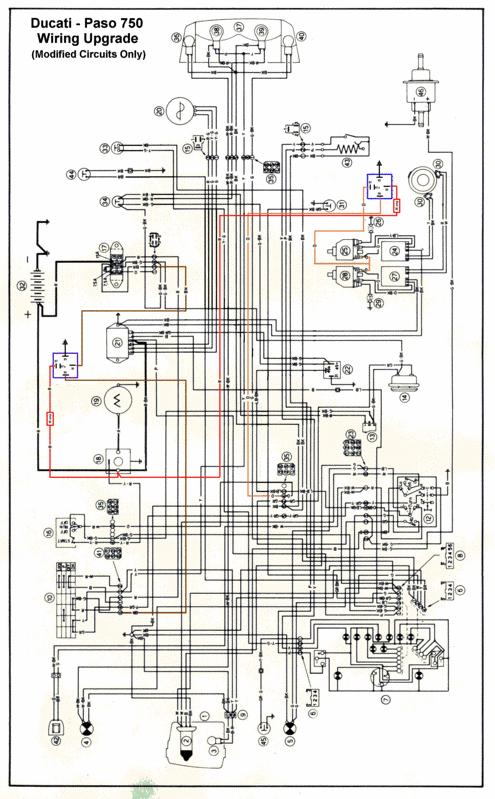
1 750 Paso Wiring Upgrade Supplies required: 2 Bosch 30A/12V Relays # # (with mounting tab) 1 30 Amp fuse holder 1 10 Amp fuse holder 12 inches of brown 12 gauge wire 60 inches of red 14 gauge wire 24 inches of black 14 gauge wire 12 inches of orange 14 gauge wire 12 Female push on connectors gauge (crimp or solder) 3 ring terminals gauge (crimp or solder) 1. Disconnect and remove battery. 2. Make up a black ground wire 6 long with ring terminal on one end and push on terminal on the other. 3. Pull blinker relay from rubber mount and reverse the mount bracket. Install the ground wire under the mounting screw for the blinker mount and tighten. The ring terminal should point to 5 o clock (see pic) so that it doesn t interfere with the mounting of the new main power relay. Blinker relay mount Mounting bolt New main power relay 4. Unplug main power feed wire under tank. Cut any wire ties that may be on the harness and wiggle the plug back and forth to loosen. Brown wire that will be cut 5. Slide back the rubber cover that is over the harness and cut the BROWN wire about 2 inches from the plug. Pull the brown wire back through the harness, strip and mount a push on connector. This will be put onto terminal # 30 on the relay. 6. Strip and mount a ring terminal on one end of the 30 Amp fuse holder and a push on connector onto the other end.
. On my Paso this is the bottom terminal.")


2 Starter Solenoid Upper terminal on my Paso connects to the starter cable The lower terminal connects to the battery POSITVE terminal 7. Mount the ring end of the fuse holder to the terminal of the starter solenoid that is connected to the battery feed cable (the other cable goes to the starter). On my Paso this is the bottom terminal. Yours may be different!! The other end mounts to terminal # 87 on the relay. Leave the nut loose to make installing the coil feed easier. New Main feed relay Regulator Starter Solenoid Fuse Panel Brown wire cut from harness Ignition box 8. Cut a piece of brown wire and feed it up through the rubber covering on the wire harness and connect to the remaining brown wire at the harness plug. I soldered this joint but you could use a crimp on barrel connector. On the other end of this wire, crimp on a push on terminal. Mount this wire to terminal 86 on the relay. Place harness back in original position and connect the plug. 9. Push the ground wire onto terminal 85 and install the relay onto the bolt that holds the electric plate mounting screw. Push blinker relay back into the rubber mount. Brown wire spliced to harness near the plug Brown wire cut from harness that goes to the fuse panel Power feed from starter solenoid. 30 Amp fuse NOT USED!! Common Relay Pin Configuration (Bosch-type)


3 Part 2 Coil Relay New Relay New power feed wire Coils Ground Wire 1. Pull the 2 orange wires off of the coils. You will use one of these to switch the relay, mount to post # 86 and the other will go unused. I just taped off the extra connector to keep it out of the way. 2. Mount the new relay on the frame tube as shown in the picture above with a tie wrap. 3. On about a 60 piece of 14 gauge RED wire install a 10 Amp fuse holder and mount a ring terminal on one end and install it onto the starter solenoid lower terminal (or the one that is connected to the battery). Tighten. 10 Amp Fuse holder 4. Run the new power feed wire along the frame to where the new relay is installed. Follow the existing wire harness and slip the wire under any existing wire ties. New feed wire running along frame and existing harness

4 5. Cut the new feed wire to length and mount a push-on connector and install on terminal #30 of the relay. 6. Make up a ground wire from black 14 gauge with a ring terminal on one and a push on connector on the other. The wire only needs to be long enough to reach the mounting bolt for the coils. The wire connects to the #85 terminal on the relay. Install under the bolt and tighten. New power wires from relay to coils 7. The new power feed to the coils is a Y (see below) that has a push on terminal on each end. This will take the power from the #87 terminal of the relay and feed it to the 2 coils. Install a push on terminal on one end of each wire and then push the 2 wire ends into 1 push-on terminal and crimp. To Terminal #87 To terminal on Coils Orange wire that was originally connected to the coils Power feed from starter solenoid. 10 Amp fuse Orange Y wire harness to the coils NOT USED!! 8. Inspect all connections and install battery.
5 Notes DO NOT perform this work with the battery connected. This upgrade will take 3-4 hours. All of these items used in the upgrade are available at your local auto-parts store. I soldered most connections and then used heat shrink tubing over the soldered area. I did use some crimp on connector shown in the picture but will change then to solder type. I feel that the solder type is a better connection than a crimp on connector. I offer this information in good faith, but with no warranty as to the accuracy or suitability to other makes and models. You perform this work at your own risk.
6
Installing Ignition Coil relay
 Installing Ignition Coil relay Above is a schematic diagram of the coil relay modification. All it really does is, it uses the existing 12 Volt positive that normally powers the coils, to power a relay,
Wiper motor bolt and spacer. 3. Place relays as shown in picture so you can route the wires.
 TSB Fan Relay Kit Please refer to a factory repair manual when working on your car. 1. Disconnect battery cables from the battery. 2. Remove bolt and spacer from wiper motor as shown in the picture. Wiper
Disconnect the battery power from the car.
 Adding a safety fuse to the ignition circuit of 1956 to 1962 Corvettes Part 1 is for 1958 to 1962. Part 2 is for 1956 to 1957 Rich Mozzetta and Dave Zuberer Part 1-1958 to 1962 Here is a way to add a fuse
INSTALLATION INSTRUCTIONS
 INSTALLATION INSTRUCTIONS Electric Vacuum Pump Kit 28146 Thank you for choosing STAINLESS STEEL BRAKES CORPORATION for your braking needs. Pleases take the time to read and carefully follow these instructions
Control Panel Interface Upgrade Installation Guide For Model 200i and 250i Motorcycle Dynamometers Serial Number 202xxxx.
 2004 Dynojet Research, Inc. All Rights Reserved. Control Panel Interface Upgrade Installation Guide For Model 200i and 250i Motorcycle Dynamometers Serial Number 202xxxx. This manual is copyrighted by
 Page 1 of 14 This install requires work on your supplemental restraint system and could cause injury or damage to your car. If you are not comfortable performing the steps detailed here then do not attempt
Connecting the rear fog light on the A4 Jetta, while keeping the 5 Light Mod
 Connecting the rear fog light on the A4 Jetta, while keeping the 5 Light Mod DISCLAIMER: I'm human and make mistakes. If you spot one in this how to, tell me and I'll fix it This was done on my 99.5 Jetta.
INSTALLATION INSTRUCTIONS
 2015 - Ford Mustang Qi Wireless Charging Kit (Kit # FDMC-1222) Please read thoroughly before starting installation and check that kit contents are complete. Items Included in the Kit: Qi Wireless Charging
Z8 Engine Start Button Install for the BMW E46 3 Series
 Z8 Engine Start Button Install for the BMW E46 3 Series This write up is a specific installation of a Z8 engine start button on the E46, but it can be used as a general guide for an engine start button
MSD 6AL Ignition Module w/ Rev Control - Installation Instructions
 MSD 6AL Ignition Module w/ Rev Control - Installation Instructions The below installation instructions work for the following products: MSD 6AL Ignition Module w/ Rev Control Please read through the instructions
Fog Light setup for a 2003 XL F250 Super Duty using the OEM kit.
 Fog Light setup for a 2003 XL F250 Super Duty using the 2005-2007 OEM kit. Since the kit (1C3Z15200BB) for the 2001-2004 series truck was not available anymore, I explored options to put a set of OEM fog
Rostra Electronic Cruise Control Install On a Stratoliner or Roadliner
 Rostra Electronic Cruise Control Install On a Stratoliner or Roadliner MATERIALS LIST: 1 - Rostra Part # 250-1223 (www.brandondist.com/products/cruise1223.htm) 1 - Signal Splitter part # 250-4369 1 - Engagement
We have had a request for instructions on how to replace the 50 AMP CR relay in the A/C electrical box with the upgraded 70 AMP relay.
 We have had a request for instructions on how to replace the 50 AMP CR relay in the A/C electrical box with the upgraded 70 AMP relay. This Carolina Thomas Bus Buzz provides instructions as to how we go
Installation of Auto Meter Cobalt Boost/Vacuum Gauge:
 Installation of Auto Meter Cobalt Boost/Vacuum Gauge: Fitment: All 79-14 models. This installation was completed on a 2004 Mustang GT, and should be identical for all 1999-2004 model Mustangs. Time needed:
Stand Alone Fog Lights Installation Instructions
 Tools Required: 1. Trim Removal tool or protected flat screwdriver 2. #2 Phillips Screwdriver 3. 10mm socket 4. 10mm wrench 5. 8mm or 5/16 socket 6. Adjustable Pliers 7. Electrical Tape WARNING!!! Disconnect
Handyman Motor Capacitor Meter PART NO
 Handyman Motor Capacitor Meter PART NO. 2225174 To test a motor-run capacitor in the field with no capacitance meter at hand, you had to hook up the capacitor through an extension cable to a 120V wall
Installation Instructions for the Plug & Play Remote Start Package (EVOCHR4)
") T6002 v1.1 02/2013 Installation Instructions for the Plug & Play Remote Start Package (EVOCHR4) For CHRYSLER Town & Country 2008-2012 Review the remote start installation manual for safety instructions!
T6002 v1.1 02/2013 Installation Instructions for the Plug & Play Remote Start Package (EVOCHR4) For CHRYSLER Town & Country 2008-2012 Review the remote start installation manual for safety instructions!
Installation Instructions
 Installation Instructions Jeep JK 2-Door (2011 Present) Mounting Bracket and Air Line System Kit for ARB On-Board Twin Air Compressor (CKMTA12) Made in the USA Kit Contents: 1 Flat Bracket 1 Formed Bracket
Installation Instructions for Stand Alone Remote Starter (EVO-ALL-THAR-GM2) Firmware: 4.18, OPTION 15. T2362 Rev#1.2 last updated 10/15/13
 Firmware: 4.18, OPTION 15. T2362 Rev#1.2 last updated 10/15/13") Installation Instructions for Stand Alone Remote Starter (EVO-ALL-THAR-GM2) Firmware: 4.18, OPTION 15. T2362 Rev#1.2 last updated 10/15/13 -The new EVO-ALL interface module eliminates the need for a separate
Installation Instructions for Stand Alone Remote Starter (EVO-ALL-THAR-GM2) Firmware: 4.18, OPTION 15. T2362 Rev#1.2 last updated 10/15/13 -The new EVO-ALL interface module eliminates the need for a separate
Installation Tips - (Crimestopper RS1/RS2) & (Fortin EVO-ALL 5): *regular key & automatic transmission only*
 & (Fortin EVO-ALL 5): *regular key & automatic transmission only*") Installation Tips - (Crimestopper RS1/RS2) & (Fortin EVO-ALL 5): TIP SHEET T3385f, T3413f *regular key & automatic transmission only* Thank you for purchasing your remote start from MyPushcart.com - an
Installation Tips - (Crimestopper RS1/RS2) & (Fortin EVO-ALL 5): TIP SHEET T3385f, T3413f *regular key & automatic transmission only* Thank you for purchasing your remote start from MyPushcart.com - an
Installation Instructions for the Plug & Play Chrysler/Dodge/Jeep Remote Start Package w/mux T5
 v1.01 12/14/2102 Installation Instructions for the Plug & Play Chrysler/Dodge/Jeep Remote Start Package w/mux T5 Review the remote start installation manual for safety instructions! Overview Your kit consists
HOW TO FIT A KEYLESS ENTRY SYSTEM
 HOW TO FIT A KEYLESS ENTRY SYSTEM THE KITS ARE WIDELY AVAILABLE TO BUY FROM THE INTERNET AND OTHER GOOD STOCKISTS HERE IS AN IDEA OF WHAT YOU SHOULD RECIEVE IN YOUR KIT. PLUS WIRING DIAGRAM PLUS WIRING
Two panel Sequential LED Taillight kit installation guide
 1970 CHEVELLE Two panel Sequential LED Taillight kit installation guide Kit Contents: 2 LED panels 2 rubber grommets 1 power wire with t-tap 1 driver side LED harness, 24 1 passenger side LED harness,
In This DIY We Will Show You How To Install Recon Backup Lamps (part # To Run On A Separate Switch & In Reverse.
 In This DIY We Will Show You How To Install Recon Backup Lamps (part # 264150 To Run On A Separate Switch & In Reverse. Please Note, There Are Many Ways of Installing These Lights, Including Wiring Methods,
Installation Instructions for Key Switch SNOWRATOR
 2017 Installation Instructions for Key Switch SNOWRATOR We appreciate your purchase of L.T. Rich s Product. Please read carefully before Operating or detaching. AES L.T.RICH 6/15/2017 SHIPPING CONTENTS...
ISIS Power Manual and Installation Guide Race Car Replicas- Superlite Coupe
 ISIS Power Manual and Installation Guide Race Car Replicas- Superlite Coupe Table of Contents Overview... 2 System Details... 3 Kit Includes... 3 Technical Specifications... 3 Harness Descriptions... 4
Guardian GRD502-A Adapter Matrix
 Guardian GRD502-A Adapter Matrix Note: Based on vehicle age and transmission code, it may be necessary to use one of the adapters listed below along with the GRD501 or GRD502 part number. Adapter Application
Nissan GTR Alpha Fuel System
 Nissan GTR Alpha Fuel System Instructions V5 The goal of AMS is to provide the highest quality, best performing products available. By utilizing research and development, and rigorous testing programs
TTR225/250 DUAL S PORT K IT I NSTALLATION I NSTRUCTIONS
 TTR225/250 DUAL S PORT K IT I NSTALLATION I NSTRUCTIONS KIT CONTENTS Inspect Your Kit Your kit will include the following items A. TTR225/250 Instructions and Wiring Diagrams Read through the entire instruction
USB Charge Port Installation Instructions
 USB Charge Port Installation Instructions Lifetime Technical Support support@logolites.com 770-476-7322 www.logolites.com Manual 100-0014C Thank you for purchasing a Logo Lites USB Charge Port! USB Charge
Detroit Speed, Inc. Selecta-Speed Wiper Kit Corvette P/N:
 Detroit Speed, Inc. Selecta-Speed Wiper Kit 1963-67 Corvette P/N: 121620 A downpour of rain will no longer hinder your ability to clearly see the road. The Detroit Speed Selecta-Speed Wiper Kit provides
SYSTEM OPERATION IMPORTANT CAUTIONS
 SYSTEM OPERATION The system is turned on by placing the gear shift lever in the reverse position. The green light on the cab Control Box will illuminate to indicate the system is operating. When an object
Installing the Throttle Commander Ford F250 F550 Super Duty
 Installing the Throttle Commander Ford F250 F550 Super Duty 7.3L Power Stroke Diesel 1996 up to 2001.25 T500011 and T500028 1.0 Preparing for Installation...5 2.0 Installing the Throttle Controller...5
Installation Instructions for the Plug & Play Remote Start Package (EVOCHR5)
") T6018 v1.1 02/2013 Installation Instructions for the Plug & Play Remote Start Package (EVOCHR5) For DODGE Nitro 2007-2011 Review the remote start installation manual for safety instructions! Overview Your
T6018 v1.1 02/2013 Installation Instructions for the Plug & Play Remote Start Package (EVOCHR5) For DODGE Nitro 2007-2011 Review the remote start installation manual for safety instructions! Overview Your
PN CHEVY TRI-FIVE. Kit Contents: Four panel Sequential LED Taillight kit installation guide
 Four panel Sequential LED Taillight kit installation guide Kit Contents: 2 tail light LED panels 2 tail light turn signal LED panels 1 rubber boot/sleeve kit 1 power wire with t-tap 1 driver side LED harness,
Installation Tips for your RS-1 + Honda-SL3 (1.b) Remote starter Honda: ( FIT), ( Pilot), ( Ridgeline) Acura: ( MDX)
 Remote starter Honda: ( FIT), ( Pilot), ( Ridgeline) Acura: ( MDX)") Installation Tips for your RS-1 + Honda-SL3 (1.b) Remote starter Honda: ( 06-08 FIT), ( 05-08 Pilot), ( 06-13 Ridgeline) Acura: ( 03-06 MDX) TIP SHEET T0777 Thank you for purchasing your remote start from
Installation Tips for your RS-1 + Honda-SL3 (1.b) Remote starter Honda: ( 06-08 FIT), ( 05-08 Pilot), ( 06-13 Ridgeline) Acura: ( 03-06 MDX) TIP SHEET T0777 Thank you for purchasing your remote start from
Installation Instructions
 Installation Instructions Jeep JK Unlimited (2007 Present) Mounting Bracket and Air Line System Kit for ARB On-Board Twin Air Compressor (CKMTA12) Made in the USA Kit Contents: 1 Bracket for ARB Compressor
EasyStart 364 (ASY-364-X20-IP) Installation Instructions for the Coleman / Airxcel Air Conditioners
 Installation Instructions for the Coleman / Airxcel Air Conditioners") EasyStart 364 (ASY-364-X20-IP) Installation Instructions for the Coleman / Airxcel Air Conditioners using Installation Kit KIT-364-CM1 Contents Introduction... 2 Safety first... 2 Making a good crimp...
EasyStart 364 (ASY-364-X20-IP) Installation Instructions for the Coleman / Airxcel Air Conditioners using Installation Kit KIT-364-CM1 Contents Introduction... 2 Safety first... 2 Making a good crimp...
jegs.com
 Contents Wiring Harness w/ Fuse Panel Installation Instructions Turn Signal Plug w/ Terminals 2 Headlight Plugs 3/4 Grommet 10 ¼ Terminals 4 Ring Terminals 10 Wire Ties Fusible Link 2 Screws & Nuts 2 Plastic
INSTALLATION AND USER MANUAL
 INSTALLATION AND USER MANUAL SDKIT-730 & SDKIT-734 100% Bolt-On 150 PSI Train Horn System for 2011-2015 F-250 & F-350 Super Duty P/N SDKIT-730 P/N SDKIT-734 Thank you for purchasing a Kleinn Air Horns
Guardian Personal Mobility Lift Interlock GRD701-AR ( Dodge Sprinter) Installation Instructions
 Installation Instructions") An ISO 9001:2000 Registered Company Guardian Personal Mobility Lift Interlock GRD701-AR (2007-2008 Dodge Sprinter) Installation Instructions GUARDIAN MODULE Remove drivers seat and step-well trim for access.
An ISO 9001:2000 Registered Company Guardian Personal Mobility Lift Interlock GRD701-AR (2007-2008 Dodge Sprinter) Installation Instructions GUARDIAN MODULE Remove drivers seat and step-well trim for access.
Installation Tips for your Crimestopper/ProStart Remote Start system (for GM vehicles) v1.01 updated 2/27/2012
 v1.01 updated 2/27/2012") Installation Tips for your Crimestopper/ProStart Remote Start system (for GM vehicles) v1.01 updated 2/27/2012 Thank you for purchasing your remote start from MyPushcart.com - an industry leader in providing
Installation Tips for your Crimestopper/ProStart Remote Start system (for GM vehicles) v1.01 updated 2/27/2012 Thank you for purchasing your remote start from MyPushcart.com - an industry leader in providing
Replacing stock Ducati relays with solid state type
 Replacing stock Ducati 748-916-996 relays with solid state type Ducati stock relays are basically just the ordinary automotive type in a waterproof housing. They suffer from wear & tear as they contain
Instructions on installing the R/R to the front battery cover.
 April, 2008 Instructions on installing the R/R to the front battery cover. Please read all of the steps so you will be familiar with the complete relocation installation first. The purpose of this relocation
Wire Harness Installation Instructions
 Wire Harness Installation Instructions For Installing: Part #50001 Race Car Kit/8 Circuit Part #50201 8 Switch Dash Mounted Panel Part #50202 8 Switch Roll Bar Mounted Panel Manual #90502 Painless Performance
SCHNITZ. Racing SCB-PPI Programmable Power Interrupt Installation and Operation Instructions
 SCB-PPI Programmable Power Interrupt Installation and Operation Instructions Description The SCB-PPI Programmable Power Interrupt is a fully digital and programmable unit used to interrupt the coil charge
Guardian GRD501-AR Adapter Matrix
 An ISO 9001:2008 Registered Company Guardian GRD501-AR Adapter Matrix Note: Based on vehicle age and transmission code, it may be necessary to use one of the adapters listed below along with the GRD501
PRODUCT: TJ/LJ Low Profile Led Light Kit READ INSTRUCTIONS IN FULL BEFORE INSTALLATION. QUESTIONS? CALL M-F 7:00 AM 5:00 PM PST
 PRODUCT: TJ/LJ Low Profile Led Light Kit READ INSTRUCTIONS IN FULL BEFORE INSTALLATION. QUESTIONS? CALL 916-631-8071 M-F 7:00 AM 5:00 PM PST REV: E 07-01-2015 II-2208 The MetalCloak experience includes
Installation Tips for your Remote Start system (for RS4LX>GMBP for GM vehicles)
") Installation Tips for your Remote Start system (for RS4LX>GMBP for GM vehicles) Thank you for purchasing your remote start from MyPushcart.com - an industry leader in providing remote starts to doit-yourself
Installation Tips for your Remote Start system (for RS4LX>GMBP for GM vehicles) Thank you for purchasing your remote start from MyPushcart.com - an industry leader in providing remote starts to doit-yourself
72 Mustang Mach 1 tachometer cluster and gauge conversion
 72 Mustang Mach 1 tachometer cluster and gauge conversion Dated: 02-17-2009 (drafted by a Chevy person working on his first Ford -not good-) Revised: 11-05-2010 The following information pertains to how
Retro it Steering Column
 Retro it Steering Column INSTALLATION INSTRUCTIONS for 1970-74 Cuda/Challenger FOR PART NUMBER S: 1620810010, 1620810020, 1620810051, 1620820010, 1620820020, 1620820051 S I NCE 1986 Instruction # 8000000005
Aux. Battery and Isolator
 Aux. Battery and Isolator ISOLATOR MOUNTING ALL YEAR VANAGONS Fig.1 1. Disconnect ground from main battery under passenger seat 2. Remove driver seat 3. Remove driver seat belt buckle from seat pedestal
CTC 200 Cab Trailer Communication Power Line Carrier Technology Communications for Trucks and Trailers
 WHEEL MONITOR CTC 200 Cab Trailer Communication Power Line Carrier Technology Communications for Trucks and Trailers Installation Manual for the CTC-200 Modules 2004 Wheel Monitor Inc. 1-905-641-0024 Page
ELECTRICAL SYSTEM UPGRADE
 NEW CONTROLLER & ELECTRICAL SYSTEM UPGRADE FOR DAIRY TECH, INCORPORATED 10, 30 & 60G PASTEURIZERS Parts to Include 2 Wire ties (Nuts) 2 sticky wire mount pads Large Rubber Grommet (for bottom of electric
CLASSIC UPDATE WIRING KIT
 by Randy Irwin 1955-57 CLASSIC UPDATE WIRING KIT Randy Irwin - Technical Writer Randy has been involved in the Chevy parts business for over 25 years. He is a wizard at creating, making and modifying custom
ALTERNATOR PRECAUTIONS. Some precautions should be taken when working on this, or any other, AC charging system.
 The alternator charging system is a negative (-) ground system which consists of an alternator, a regulator, a charge indicator, a storage battery and wiring connecting the components, and fuse link wire.
Special Note About The JDM High Performance Water Pump:
 Page 1 of 30 JDM Engineering, Inc. home Call Us! 732-780- 0770 back to Installation Instructions Electric Fan Upgrade Kit Electric Fan Wiring Diagram Thank you for your purchase of the JDM Engineering
PLEASE READ ALL DIRECTIONS BEFORE STARTING INSTALLATION
 2008-2010 Kawasaki ZX-10R Installation Instructions PARTS LIST 1 Ignition Module 1 Installation Guide 2 Velcro strips 1 Alcohol swab 1 CAN link cable 1 USB cable THE VEHICLE S IGNITION MUST BE TURNED OFF
Retro it Steering Column
 Retro it Steering Column INSTALLATION INSTRUCTIONS for 1976-86 CJ5 & CJ7 FOR PART NUMBER S: 1520800010, 1520800020, 1520800051, 1526800010, 1526800020, 1526800051 S I NCE 1986 Instruction # 8000000010
 510564 OPYRIGHT 2013 American Autowire / Factory-Fit Used with express permission of American Autowire / Factory- Fit Page 1 92971174 Rev 0.0 6/18/2015 UNSEALED ONNETORS The connectors, sockets, wires,
LightSaver. Installation instructions, Classic GMT-800 GM truck/suv. By: BT DieselWorks, LLC. 12/2012
 LightSaver Installation instructions, 2001-2002 Classic GMT-800 GM truck/suv By: BT DieselWorks, LLC. 12/2012 First of all, thank-you for purchasing the BT DieselWorks LightSaver smart headlight control
Hush-O-Matic MRS Control Package
 Hush-O-Matic MRS Control Package 06-49192 Congratulations on your purchase! The Hush-O-Matic MRS Control package allows you to choose a few different modes including always quiet and always loud. Controlling
CUMMINS 6.7L EXHAUST BRAKE PRXB EXHAUST BRAKE KIT FOR 2007½-2015 TRUCKS EQUIPPED WITH 6.7L CUMMINS ISB DIESEL ENGINES. C Kit C Kit
 CUMMINS 6.7L EXHAUST BRAKE PRXB EXHAUST BRAKE KIT FOR 2007½-2015 TRUCKS EQUIPPED WITH 6.7L CUMMINS ISB DIESEL ENGINES C44038 4 Kit C44039 5 Kit BEFORE STARTING THE INSTALLATION please read the entire installation
Intelligent Lift Interlock System Installation Instructions
 Intelligent Lift Interlock System Installation Instructions MB 45/55 & International 3200 w/allison 2200/2400 Transmission & Shift Lock Solenoid Allison Generation 3 Controls Part # ILIS801-D 2002-2006
FORD MUSTANG. Two Panel Sequential LED Tail Light Kit Installation Guide
 1967-68 FORD MUSTANG Two Panel Sequential LED Tail Light Kit Installation Guide Kit Contents: 2 LED panels 2 rubber grommets 1 power wire with t-tap 1 driver side LED harness, 24 1 passenger side LED harness,
X-Type w/ non-premium sound amplifier installation instructions
 X-Type w/ non-premium sound amplifier installation instructions 1. Pull radio from dash (see Radio Removal Instructions ) 2. Disconnect wiring harness from back of radio by pushing in tab on plug and pulling
Fabricating and Installing Headlight Relays. Mike Graham
 Fabricating and Installing Headlight Relays Mike Graham For some time I had been reading about the benefits of installing headlight relays. As I understand it, there are two principal benefits: the load
Installation Tips for your Crimestopper/ProStart Remote Start system (add-on for GM vehicles) v1.02 updated 1/16/2013
 v1.02 updated 1/16/2013") Installation Tips for your Crimestopper/ProStart Remote Start system (add-on for GM vehicles) v1.02 updated 1/16/2013 Thank you for purchasing your remote start from MyPushcart.com - an industry leader
Installation Tips for your Crimestopper/ProStart Remote Start system (add-on for GM vehicles) v1.02 updated 1/16/2013 Thank you for purchasing your remote start from MyPushcart.com - an industry leader
2T MY and X Trainer MY oil injection and Electrical trouble shooting guide
 2T MY 2016-18 and X Trainer MY 2015-18 oil injection and Electrical trouble shooting guide General information 1. Before performing the following diagnostic procedures, check wiring plugs and terminals
LED Driving Light Set For 2014 & Newer Can-Am Spyder RT # CA006-RT
 LED Driving Light Set For 2014 & Newer Can-Am Spyder RT # CA006-RT 1. Lay-out and familiarize yourself with the components supplied with this set. 2. Remove the left mirror by pulling firmly outward on
A. Preparing the charge harness. Start by removing the plastic covers by the battery terminal.
 twist battery relocate kit and harness. Step 1 A. Remove battery. Start by removing the negative battery cable and then the positive. After removing the battery cables remove the battery hold down bracket.
SPEED CONTROL 4 AND 6 CYL. JEEP WRANGLER. Read entire instructions thoroughly before starting. INSTALLATION INSTRUCTIONS TOOLS REQUIRED:
 Read entire instructions thoroughly before starting. TOOLS REQUIRED: SPEED CONTROL 4 AND 6 CYL. JEEP WRANGLER INSTALLATION INSTRUCTIONS Complete socket set Phillips screwdriver Torx drivers Wire strippers/cutters
RS4 / RS7 + (4) + SPDT
 + SPDT") TIP SHEET Installation Tips for RS4 / RS7 + Honda-SL3 (4) + SPDT + Diode x2 T0776, T0731 Honda: ( 08-12 Accord), ( 12-13 Civic), 12-13 CRV), ( 11-13 Odyssey), ( 09-13 Pilot) Acura: ( 09-13 TSX) Thank you
TIP SHEET Installation Tips for RS4 / RS7 + Honda-SL3 (4) + SPDT + Diode x2 T0776, T0731 Honda: ( 08-12 Accord), ( 12-13 Civic), 12-13 CRV), ( 11-13 Odyssey), ( 09-13 Pilot) Acura: ( 09-13 TSX) Thank you
Control Replacement # Page 1 REPLACEMENT OF OBSOLETE SEMI- AUTO CONTROLS WITH KIT #
 Control Replacement #500643 Page 1 R epla c ement of s emi-a uto c ontr ols with r epla c ement kit # 500643 Content CONTENTS Control Replacement 2 Calibration 5 Operating Instructions 6 Preventive Maintenance
Installation Instructions for Lingenfelter GM 2500 Suburban & Yukon XL Auxiliary Fan System (with AC clutch controlled fan output)
") Installation Instructions for Lingenfelter 2007-2013 GM 2500 Suburban & Yukon XL Auxiliary Fan System (with AC clutch controlled fan output) PN L300080607 Revision - 1.1 Lingenfelter Performance Engineering
Installation Instructions for Lingenfelter 2007-2013 GM 2500 Suburban & Yukon XL Auxiliary Fan System (with AC clutch controlled fan output) PN L300080607 Revision - 1.1 Lingenfelter Performance Engineering
Installation Manual for VMAC Throttle Commander Throttle Control T500111
 Installation Manual for VMAC Throttle Commander Throttle Control T500111 2006-2007 Classic GMC CK2500-3500 6.0L Gasoline Engines 1.0 Preparation for Installation...4 1.1 Automatic Transmission Trucks...4
Custom Dynamics Spyder Stingerz Installation Instructions
 Custom Dynamics Spyder Stingerz Installation Instructions We thank you for purchasing the Custom Dynamics Stingerz! Our products utilize the latest technology and high quality components to ensure you
OLDSMOBILE CUTLASS
 1971-72 OLDSMOBILE CUTLASS Four Panel Sequential LED Tail Light Kit Installation Guide Kit Contents: 4 LED panels 1 Connector/Wire Kit 1 Grommet/Boot Kit 1 Power wire 2 Pigtail Harness Kits 1 Crimp terminal
56462 CabCommand HAND-HELD CONTROL Installation Instructions
 Western Products PO Box 245038 Milwaukee, WI 53224-9538 www.westernplows.com A DIVISION OF DOUGLAS DYNAMICS, L.L.C. 56462 CabCommand HAND-HELD CONTROL Installation Instructions Read this document before
* * APPLICABLE MODELS: 2014 > Mazda 3
 PART NUMBER: 0000 8C L48 (DIO) / 0000 89 L84 (PIO) GENUINE ACCESSORIES INSTALLATION INSTRUCTIONS Rev. AAA *550-0700-000* APPLICABLE MODELS: 2014 > Mazda 3 REQUIRED COMPONENTS: ITEM QTY DESCRIPTION Usage
Four Panel Sequential LED Tail Light Kit Installation Guide
 1969 CHEVY CAMARO Four Panel Sequential LED Tail Light Kit Installation Guide Kit Contents: 4 LED panels 4 rubber grommets 1 power wire with t-tap 2 driver side LED harnesses, 24 2 passenger side LED harnesses,
BMW 2002 M42 Swap Notes-THIS IS NOT FINISHED
 BMW 2002 M42 Swap Notes-THIS IS NOT FINISHED This document is to help those that want to install an m42 into a BMW 2002. It is based around an e30 engine, trans, and wiring. You can use the e36 block/head/wiring
Modifying the exterior lighting of the Ram truck
 Modifying the exterior lighting of the Ram truck The Ram truck has been designed and developed using standard incandescent lights. These lights are controlled by a computerized module called the Central
MAVERICK, PINTO. Two Panel Sequential LED Tail Light Kit Installation Guide
 1970-77 MAVERICK, 71-76 PINTO Two Panel Sequential LED Tail Light Kit Installation Guide Kit Contents: 2 LED panels 2 rubber grommets 1 power wire with t-tap 1 driver side LED harness, 24 1 passenger side
Installation Instructions
 Installation Instructions These instructions cover the following kits: 64-66 Mustang Sequential Turn Signal LED kit 67-68 Mustang Sequential Turn Signal LED kit Kit Contents 2 x LED Tail Light Panels 2
CHEVY NOVA w/reverse Four Panel Sequential LED Taillight Kit Installation Guide
 1970-72 CHEVY NOVA w/reverse Four Panel Sequential LED Taillight Kit Installation Guide Kit Contents: 4 LED panels 4 rubber grommets 1 power wire with t-tap 1 driver side LED harness, 24 (5 pin) 1 passenger
* * APPLICABLE MODELS: 2014 > Mazda 6
 PART NUMBER: 0000 8C H02(DIO) / 0000 89 H18(PIO) GENUINE ACCESSORIES INSTALLATION INSTRUCTIONS Rev. AAA *550-0694-000* APPLICABLE MODELS: 2014 > Mazda 6 REQUIRED COMPONENTS: ITEM QTY DESCRIPTION Usage
Trail Rocker Installation Instructions
 Trail Rocker Installation Instructions Manual #90581 For Installing Painless Part Numbers: 57002 Painless Performance Products recommends you, the installer, read this installation manual from front to
FULL SIZE RANGE ROVER REMOTE STARTER INSTALLATION INSTRUCTIONS
 2010-2012 FULL SIZE RANGE ROVER REMOTE STARTER INSTALLATION INSTRUCTIONS During your first installation of this product, you will benefit from these complete instructions. After performing two or three,
RS4/RS7 + + SPDT T0776,T0731
 TIP SHEET Installation Tips for your RS4/RS7 + Honda-SL3 (1.a) + SPDT T0776,T0731 Honda: ( 03-07 Accord),( 01-05 Civic),( 02-06 CRV),( 03-10 Element),( 05-10 Odyssey) Acura: ( 01-03 EL),( 02-06 RSX),(
Installation Instructions Jeep CJ-7
 Retrofit Steering Column Installation Instructions 1976-86 Jeep CJ-7 For Part # s 1520800010, 152800020, 1520800051 www.ididitinc.com 610 S. Maumee St., Tecumseh, MI 49286 (517) 424-0577 (517) 424-7293
Trail Rocker Installation Instructions
 Trail Rocker Installation Instructions Manual #90580 For Installing Painless Part Numbers: 57000 and 57001 Painless Performance Products recommends you, the installer, read this installation manual from
Triumph Street Triple VSM Grip Heater Install
 Triumph Street Triple VSM Grip Heater Install Introduction: With winter fast approaching and with painful memories of last winter riding with the club it was time to do something about getting some grip
Upgrade v3 to v3.2. SeeMeCNC Guides. Upgrade v3 to v3.2. Rostock Max v3 Uprgade to v3.2. Written By: SeeMeCNC seemecnc.dozuki.
 SeeMeCNC Guides Upgrade v3 to v3.2 Rostock Max v3 Uprgade to v3.2 Written By: SeeMeCNC 2018 seemecnc.dozuki.com/ Page 1 of 34 INTRODUCTION This guide is intended to Upgrade a Rostock Max v3 to a Rostock
This is the layout of a typical harness form a TPI Camaro.
 TPI wiring harness, typical 1986-89: This is the layout of a typical harness form a 1986-88 TPI Camaro. (A) bulkhead conn. through firewall. (B) ecm conn. (C) jct. conn for fuel injectors and cooling fan.
Speed For Sale LLC Website: Telephone: Location: 3100 Engineering
 Speed For Sale LLC Website: www.speedforsale.com/nissangtrparts Email: Sales@SpeedForSale.com Telephone: 770-777-4774 Location: 3100 Engineering Parkway Alpharetta, GA 30004 SpeedForSale.com s Installation
INSTRUCTION, GPT LOW VOLTAGE THERMAL SWITCH (LVTS) INSTALLATION KIT P/N
 INSTALLATION KIT P/N") LIFT CORPORATION Sht. 1 of 9 DSG# M-07-18 Rev. ~ Date: 08/15/08 INSTRUCTION, GPT LOW VOLTAGE THERMAL SWITCH (LVTS) INSTALLATION KIT P/N 282473-01 LOW VOLTAGE THERMAL SWITCH (LVTS) P/N 905291 INSTRUCTION
LIFT CORPORATION Sht. 1 of 9 DSG# M-07-18 Rev. ~ Date: 08/15/08 INSTRUCTION, GPT LOW VOLTAGE THERMAL SWITCH (LVTS) INSTALLATION KIT P/N 282473-01 LOW VOLTAGE THERMAL SWITCH (LVTS) P/N 905291 INSTRUCTION
NOTES: 1489 N THESTA FRESNO, CA PHONE (559) FAX (559)
 FAX (559)") NOTES: 1489 N THESTA FRESNO, CA. 93703 PHONE (559)486-5444 FAX (559)486-5155 Contents: REMOTE X 2 THIS IS ONLY A GUIDE!!! BUTTON X 16 THE APPLICATIONS SHOWN ARE GENERAL GUIDE LINES OF POSSIBLE APPLICATIONS.
NOTES: 1489 N THESTA FRESNO, CA. 93703 PHONE (559)486-5444 FAX (559)486-5155 Contents: REMOTE X 2 THIS IS ONLY A GUIDE!!! BUTTON X 16 THE APPLICATIONS SHOWN ARE GENERAL GUIDE LINES OF POSSIBLE APPLICATIONS.
INSTALLATION INSTRUCTIONS
 INSTALLATION INSTRUCTIONS Electric Vacuum Pump Kit 28146 Thank you for choosing STAINLESS STEEL BRAKES CORPORATION for your braking needs. Pleases take the time to read and carefully follow these instructions
29048, 29049, 29050, 29051, 29052, 29053, 29054,
 April 15, 2014 Lit. No. 29206, Rev. 11 29048, 29049, 29050, 29051, 29052, 29053, 29054, 29400 5 HARNESS KIT 3 PORT ISOLATION MODULE LIGHT SYSTEM w/3 PLUG SYSTEM HARNESSES Installation Instructions Read