jegs.com
|
|
|
- Nicholas Bryan
- 6 years ago
- Views:
Transcription


1 Contents Wiring Harness w/ Fuse Panel Installation Instructions Turn Signal Plug w/ Terminals 2 Headlight Plugs 3/4 Grommet 10 ¼ Terminals 4 Ring Terminals 10 Wire Ties Fusible Link 2 Screws & Nuts 2 Plastic Spacers 4 14/16 Ga Butt Splice Connectors 2 10/12 Ga Butt Splice Connectors 2 Column Ignition Switch Connectors Dimmer Switch Connector Alternator Plug 6 Red #34 Wire Step By Step Instructions to Wire Your Vehicle Disconnect the battery in your vehicle before starting Read the installation instructions and look at all diagrams before proceeding Setup a plan before you get started Check your kit to make sure everything is included Lay the harness out on the floor Plan the path to which way your wires will be routed Only remove the ties holding the bundles together Leave all labels on the wiring harness until you have completely installed your kit The fuse block must be mounted near the steering column under the dash (the wires may be too short if you mount the fuse panel in another location). Mount all electrical accessories and switches where they will be on the vehicle (so that the wires are trimmed to the correct length). You may need some optional accessories and wiring components (see the listing of optional accessories at the end of this instruction sheet.
2 Grounding Grounding Symbol ( ) Ground wires are not included in this kit. Fiberglass body cars cannot use the body as a ground and must run individual ground wires from all components to the frame or engine. In most situations the ground wires must be added to connect the case of each component to the engine or chassis. Heavy gauge battery cables and grounding straps must be used between the engine/body/frame and the negative battery terminal. The best place to attach the ground strap to the engine is on a starter motor bolt to make sure the starter gets adequate voltage. All ground connections must be metal to metal connections that are free of dirt, rust, and paint. Testing Test for any problems that may occur upon installation completion with a 10 amp or small battery charger to ensure safety. Proceed with the installation only after you have read and understand all of the above steps and guidelines. Mounting Fuse Panel The Fuse Panel must be mounted near the steering column. When mounting the fuse panel, use the two plastic spacers between the fuse panel and firewall or other mounting surface (this allows room for the wires that run behind the fuse panel). Use the ¾ grommet supplied with the kit to protect the wires where they pass through the firewall. Use similar grommets (available separately) for any other wires that pass through any other panels in the vehicle. Wiring Groups The wires that are attached to the fuse panel are organized into groups based on where the wires are connected to the vehicle. Each of these wire groups are shown below along with drawings that show how to make the connections to your vehicle. In some cases there may be different drawings for each type of vehicle (i.e. GM, Ford, and Mopar). You may also need to reference a service manual for electrical drawings for other vehicles since this harness can be used with
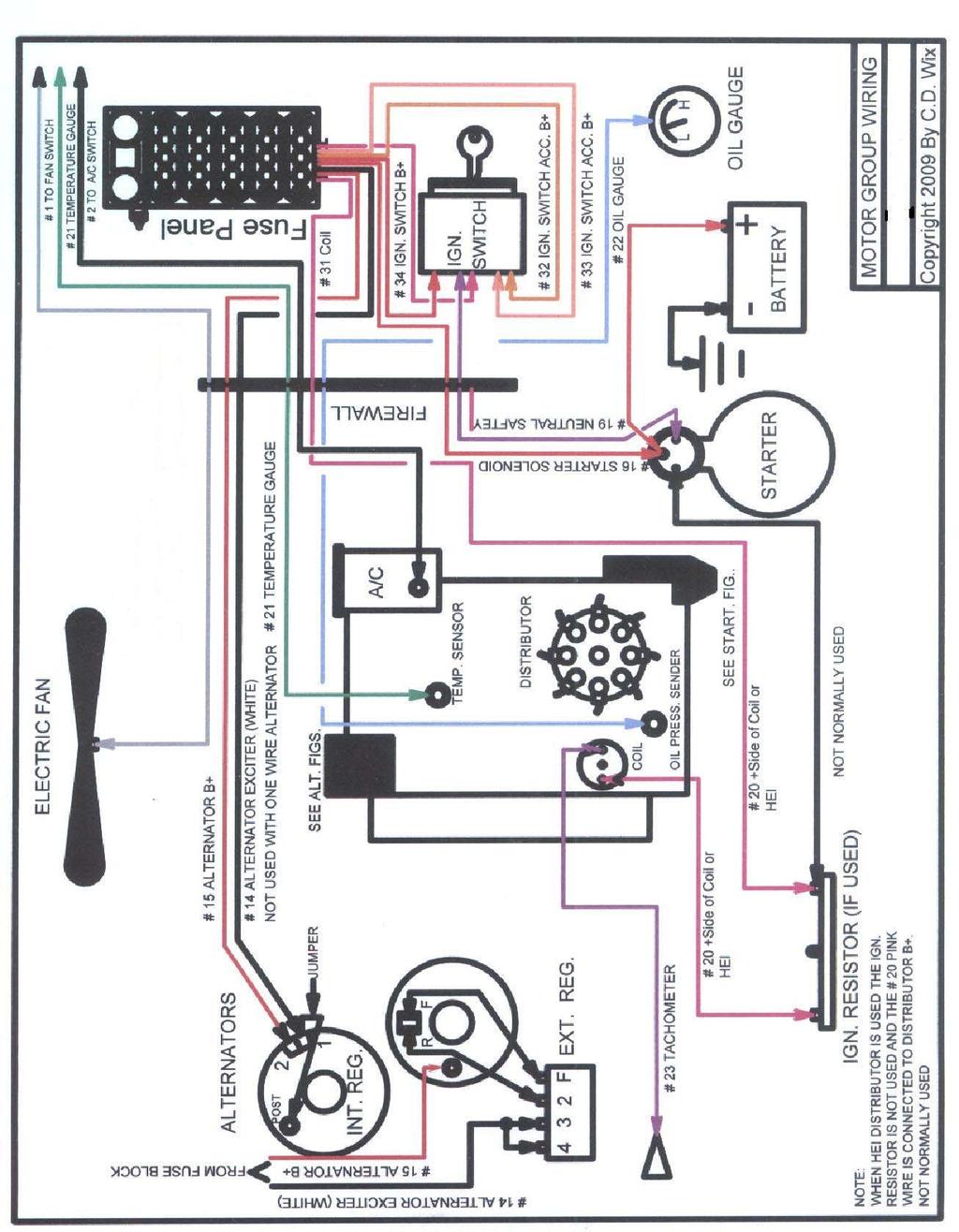
3 almost any vehicle that has the engine located in the front and the fuse panel mounted under the dash near the steering column. Motor Group Wire #14 White 16 Ga. (Alternator Exciter) Originates from the fuse panel and connects to the alternator. See the Alternator diagrams shown below. Wire #15 Red 10 Ga. (Alternator Battery) Originates from the fuse panel and connects to the battery post on the alternator. Wire #16 Red 10 Ga. (Starter Solenoid) Originates from the fuse panel and connects to the starter battery lug. Note: Crimp the gray fusible link on the end of this wire where it attaches to the large post on the starter. Wire #19 Purple 12 Ga. (Neutral Safety) Originates from the Ignition switch and connects to the neutral safety switch and then connect to the start lug on the Starter. See the ignition switch drawings in the Column Group shown below. Wire #20 Pink 14 Ga. (Coil) Originates from the fuse panel and connects to the positive side of the coil. Wire #21 Green 18 Ga. (Water Temperature Sender) Originates from the temp gauge and connects to the temperature sending unit. Wire #22 Lt. Blue 18 Ga. (Oil Pressure Sender) Originates from the oil gauge and connects to the oil pressure sending unit. Wire #23 Purple 18 Ga. (Tachometer) Originates from the tachometer gauge and connects to negative side of the coil. Wire #54 Red 18 Ga. (Electric Choke) Originates from the fuse panel and connects to the positive side of the electric choke. Wire #2 Black 14 Ga. (A/C Heat) Originates from the fuse panel and connects to the thermostat switch power.
4
5
6
7 Headlight Group H-1 # 27 Brown (Parking Lights) Originates from the headlight switch and connects to the parking lights # 26 Lt. Blue (Left Front Turn) Originates from the turn signal plug and connects to the left front turn signal light # 25 Blue (Right Front Turn) Originates from the turn signal plug and connects to the right front turn signal # 24 Green (Horn) Originates from the horn relay on the fuse panel and connects to the horn. (Relay is built into the fuse panel) # 9 Tan (Low Beam) Originates from the dimmer switch and connects to the left and right low beam headlights # 8 Lt. Green (High Beam) Originates from the dimmer switch and connects to the left and right high beam headlights # 1 Gray (Electric Fan) Originates from the accessory switch group and connects to the fan power wire
8 Electric Fan #1 Gray (Electric Fan) Originates from the fan switch or relay and connects to the electric fan. (This wire is located in the Accessory group switches) # 6 Gray (Electric Fan) Originates from the fuse panel and powers the trigger wire on the electric fan relay (This wire is located in the Accessory switches group Battery Positive) This wiring harness does not come with an electric fan relay, but it is available as an optional accessory. Manual Single Fan Harness & Relay Kit º Controlled Fan Harness & Relay Kit º Controlled Fan Harness & Relay Kit
9 Dome Light # 45 White (Dome Light) Originates from the fuse panel and hooks to the positive side of all interior lighting. Run a ground wire on the negative side of all interior lighting to all door jam switches as well as the headlight switch. Note: All door jam switches and headlight switch must be grounded
10 Accessory Group Switches Wire # 2 Black 14 Ga. (A/C Heat) Connect to thermostat switch power Wire # 1 Gray 14 Ga. (Electric Fan) Originates from the relay or switch and connects to electric fan power lead. Wire # 56 Green (Back-Up Lights) Connect to back-up light switch on shifter or transmission Accessory Group B+ Wire # 3 Tan 14 Ga. (Cigarette Lighter Power) Originates from the and connect to cigarette lighter battery positive terminal on the back of the lighter. Wire # 4 Black 14 Ga. (A/C Heater Switch Power) Originates from the Fuse Panel and connect to the heater fan switch battery positive. Wire # 5 Blue 16 Ga. (Wiper Switch Power) Originates from the fuse panel and connect to windshield wiper switch battery terminal. Wire #57 Pink Ga. (Cruise Control) Wire #6 Gray 14 Ga. (Cooling Fan Switch Power) Wire #58 Green 18 Ga. (Back-Up Light Switch Power)
11 Instrument Group Wire # 35 Red 16 Ga. (Power for Gauges) Originates from the fuse panel and connects to the positive side of each gauge Wire # 30 Red 14 Ga. (Power for Gauge Lights) Originates from the headlight switch and connects to the positive side of all dash lights Wire # 21 Green 18 Ga. (Water Temperature Sender) Originates from the temp gauge and connects to the temperature sending unit Wire # 22 Lt. Blue 18 Ga. (Oil Pressure Sender) Originates from the oil gauge and connects to the oil pressure sending unit Wire # 23 Purple 18 Ga. (Tachometer) Originates from the tachometer gauge and connects to tachometer Wire # 53 Black 18 Ga. (Relay Ground for Horn) Originates from the relay on fuse panel and connects to the horn button Wire # 36 Green 18 Ga. (High Beam Indicator) Originates from the High Beam wire # 8 and connects to the high beam indicator light. Wire # 37 Lt. Blue/Black 18 Ga. (Left Turn Indicator) Originates from the Column Group and connects to the left turn indicator light on the dash Wire # 38 Blue 18 Ga. (Right Turn Indicator) Originates from the Column Group and connects to the right turn indicator light on the dash Note: Be sure to ground all gauges to a good clean ground See Instrument Diagram shown below
12
13 Column Group # 31 Pink (Coil) Originates from the fuse panel and connects to the to the ignition switch terminal marked "IGN" # 33 Orange (Ignition Switch Accessory) Originates from the fuse panel and connects to the ignition switch terminal marked "ACC" # 34 Red (Ignition Power) Originates from the fuse panel and connects to the ignition switch terminal marked "BAT" # 19 Purple (Neutral Safety) Originates from the ignition switch and connects to the neutral safety switch. # 53 Black (Horn Ground) Originates from the horn relay located on the fuse panel and connects to the "G" terminal on the GM turn signal plug # 52 Purple ( Turn Flasher Power) Originates from the turn flasher located on the fuse panel and connects to the "L" terminal on the GM turn signal plug # 51 Brown (Emergency Flasher Power) Originates from the turn flasher located on the fuse panel and connects to the "K" terminal on the GM turn signal plug # 49 Yellow (Left Rear Turn Signal) Originates from the "M" terminal of the GM turn signal plug and connects to the left rear turn signal # 48 Lt. Green (Right Rear Turn Signal) Originates from the "N" terminal of the GM turn signal plug and connects to the right rear turn signal # 26 Lt. Blue (Left Front Turn Signal) Originates from the "H" terminal of the GM turn signal plug and connects to the left front turn signal # 25 Blue (Right Front Turn Signal) Originates from the "J" terminal of the GM turn signal plug and connects to the right front turn signal
14 # 18 White (Brake Switch to Turn Switch) Originates from the brake switch and connects to the turn signal switch terminal "P" # 7 Blue (Dimmer Switch) Originates form the headlight switch dimmer power and connects to the dimmer switch # 8 Lt. Green (High Beam) Originates from the dimmer switch high beams to the high beams on the headlights #9 Tan (Low Beam) Originates from the dimmer switch low beams to the low beams on the headlights
 is available as an optional")

15 Late Model turn signal connector (about 4-1/4 wide) is available as an optional accessory part. The late model turn signal connector is wired exactly the same as the early model.
 # 30 Red (Power For Gauge Lights) Connect each wire to the proper terminal on the headlight switch (see the drawing shown")
16 Headlight Group H-2 # 7 Blue (Dimmer Switch) # 27 Brown (Front Parking Lights) # 29 Brown (Tail Lights) #28 Red (Head Light Switch Power) # 30 Red (Power For Gauge Lights) Connect each wire to the proper terminal on the headlight switch (see the drawing shown below)
17 Radio Group # 41 Red (Radio Power) Speaker Wires and power antenna wires are not included with this wiring harness. Power Door D-1 Group # 10 Yellow ( Right Door Lock) Originates from fuse panel and connects to power wire on right power door locks # 11 Yellow (Right Power Window) Originates from fuse panel and connects to power wire on right power window switch Power Door D-2 Group # 12 Yellow ( Left Door Lock) Originates from the fuse panel and connects to the power wire on the left power door locks # 13 Yellow (Left Power Window) Originates from the fuse panel and connects to power wire on the left power window switch
18 Brake Switch Group # 17 Orange (Brake power) Connect to battery side of brake switch # 18 White (Brake Switch to Turn Switch) Originates from the brake light switch and hooks up to turn signal switch
19 Tail Group #29 Brown (Tail Light) Originates from the headlight switch and connects to the tail lights and also the license plate light. #48 Green (Right Rear Turn Signal) Originates from the turn signal switch and connects to the right rear turn lamp. #49 Yellow (Left Rear Turn Signal) Originates from the turn signal switch and connects to the left rear turn lamp. Note: On most applications, the brake lights and turn signal wires are the same filament. In this situation you only need to hook up wires # 48 & # 49 the brake lights will work through the turn signal switch on the column #55 Orange (Third Brake Light) Originates from the brake light wire #18 and connects to the third brake light ONLY # 56 Green (Back up Lights) Originates from the back up light switch and connects to the rear back up lights # 39 Pink (Fuel Sending Unit) Originates from the Fuel sender and connects to the fuel gauge "S" terminal. # 47 Yellow (Electric Fuel Pump Power) Originates from the fuse panel and connects to the fuel pump. Note: You my need a relay for the fuel pump (available separately part # ). Check the instruction sheet for your electric fuel pump to see if a relay is required. # 46 Green (Trunk Light Power) Originates from the fuse pane and connects to the positive side of the trunk light. Note: Make sure fuel tank and all lights are grounded to a good clean ground
20
21 Optional Accessories Headlight Switch & Pigtail K Windshield Wiper/Washer Switch Ignition Switch w/ Keys Headlight Dimmer Switch GM HEI Power & Tach Pigtails Push Button Switch Door Jamb Switch Hydraulic Brake Light Switch Kit K1 Master Disconnect Switch Ground Strap Ground Strap Ground Strap Fuel Pump Relay & Harness Manual Single Fan Relay & Harness Temp-Controlled Fan Relay & Harness 180º Temp-Controlled Fan Relay & Harness 195º Weatherpack Starter Kit Unsealed Connector Kit Crimp Connector Set or Heat Shrink Tubing Kit Convoluted Tubing Kit Flexbraid Wire Cover Kit Grommet Assortment Kit Fuse Assortment 555-W5368 LED Indicator Lamp Red - 1/8 Bulb LED Indicator Lamp Blue 1/8 Bulb LED Indicator Lamp Amber 1/8 Bulb LED Indicator Lamp Green 1/8 Bulb LED Indicator Lamp Red 5/16 Bulb LED Indicator Lamp Blue 5/16 Bulb LED Indicator Lamp Amber 5/16 Bulb LED Indicator Lamp Green 5/16 Bulb LED Indicator Lamp Red 1/2 Bulb LED Indicator Lamp Blue 1/2 Bulb LED Indicator Lamp Amber 1/2 Bulb LED Indicator Lamp Green 1/2 Bulb Self Fusing Silicon Tape or Wire Crimping Tool or Cut and Pull Wire Stripper Tool Convoluted Tubing Installation Tools Digital 5-Gauge Panel through Digital 6-Gauge Panel w/ Tachometer through
22 Fuse Chart Function Amp Fuse Hazard 25 Horn 20 Dome Light 10 Cigarette Lighter 20 Fuel Pump 25 Wipers 15 Gauges 20 Electric Fan 25 Power Door Locks 20 Stop Lights 20 Headlights 25 Coil 30 A/C Heat 30 Power Windows 30 Turn Signals 15 Radio 10 Use only the recommended fuse size in each circuit.
23 Wire Functions Wire Function Wire Function 1 Switched W ire 31 Ignition Hot Wire 2 Switched W ire 32 Ignition Hot Wire (Not Fused) 3 Constant Hot W ire 33 Ignition Hot Wire (Not Fused) 4 Ignition Hot Wire 34 Constant Hot W ire (Not Fused) 5 Ignition Hot Wire 35 Ignition Hot Wire 6 Ignition Hot Wire 36 Indicator 7 Headlight Switch Power 37 Indicator 8 Headlight Switch Power 38 Indicator 9 Headlight Switch Power 39 Sending Unit Wire 10 Ignition Hot Wire 41 Ignition Hot Wire 11 Constant Hot W ire 45 Constant Hot Wire 12 Ignition Hot Wire 46 Constant Hot Wire 13 Constant Hot W ire 47 Ignition Hot Wire 14 Ignition Hot Wire (Not Fused) 48 Switched Wire 15 Constant Hot Wire (Not Fused) 49 Switched Wire 16 Constant Hot Wire (Not Fused) 51 Constant Hot Wire 17 Constant Hot W ire 52 Ignition Hot Wire 18 Switched W ire 53 Ground 19 Switched W ire 54 Ignition Hot Wire 20 Ignition Hot Wire 55 Switched Wire 21 Sending Unit Wire 56 Switched Wire 22 Sending Unit Wire 57 Ignition Hot Wire 23 Sending Unit Wire 58 Ignition Hot Wire 24 Constant Hot W ire 25 Switched W ire 26 Switched W ire 27 Headlight Switch Power 28 Headlight Switch Power 29 Headlight Switch Power 30 Headlight Switch Power
INSTRUCTIONS. 20 Circuit Wiring Kit Instructions October 2009, Speedway Motors, Inc.
 1 MAIN FUSE PANEL The main fuse panel harness s designed to be mounted under the dash a the firewall in an area close to the steering column. The enclosed representation of the main dash harness shows
UNIVERSAL WIRING HARNESS Installation Manual
 UNIVERSAL WIRING HARNESS Installation Manual Terminals are provided for most connections on your wiring kit. Following the gauge manufacturer s instructions, use the terminals supplied with your gauge
-----
 ----- - - -- - - -- - -- - - NOTE: #32 WIRE DOES NOT APPLY TO 8 AND 14 CIRCUIT HARNESSES ELECTRIC FAN #1 TO FAN SWITCH (GRAY) #21 TEMP. GAUGE (GREEN) #2 TO AC SWITCH (BLACK) JUMPER WIRE ALTERNATORS
INSTRUCTIONS 12 Circuit Wiring Kit Instructions
 Fan 47 9 56 4 7 6 72 40 45 48 5 8 6 Gauge Power Temp Sender Headlight Power Power Radio Constant Power Instruments and Dash Rear of Vehicle Ignition and Lights Fuse Panel & Front of Vehicle Horn Alt Excitor
40A A 40B. Horn Relay Connector. Brake Switch. Third Brake Light. Brake Switch. Brake Switch. Wires. page 3. Rear Body Feed Wires.
 Fuse Box Connections (viewed from underside) 4D 4C 4D 0 50 300 4C 43 7 39 3 6 4 93 A 2G 2F 2E 2D 2C 2B 2G 2F 2E 40 69A 2 1 5 27 69A 3A B 40A,B 11A,B 40A 156 Dimmer Dome Feed page 2 Horn Relay 2D 2 29 40B
INSTRUCTIONS Circuit Wiring Kit Instructions _2017. Fuse Box Connections. (viewed from underside) 2018, Speedway Motors, Inc.
 2018, Speedway Motors, Inc.") Fuse Box Connections (viewed from underside) 4D 4C 100 50 300 4D 4C 4B 4A 43 107 39 103 3B 2G 104 93 2F 2E 2D 2C 2B 40 69A 102 101 105 2G 2F 2E 3A A 2A B 40A,B 27 69A 106 201, Speedway Motors, Inc. 1 Fuse
Fuse Box Connections (viewed from underside) 4D 4C 100 50 300 4D 4C 4B 4A 43 107 39 103 3B 2G 104 93 2F 2E 2D 2C 2B 40 69A 102 101 105 2G 2F 2E 3A A 2A B 40A,B 27 69A 106 201, Speedway Motors, Inc. 1 Fuse
CLASSIC UPDATE WIRING KIT
 by Randy Irwin 1955-57 CLASSIC UPDATE WIRING KIT Randy Irwin - Technical Writer Randy has been involved in the Chevy parts business for over 25 years. He is a wizard at creating, making and modifying custom
Mustang Classic Update Series Kit
 accessory rear body 19 9 11 instrument cluster and map 10A, 0 4 3 7 40G 18 30 17A 24 1A 14A 9C 8A instrument cluster 4E 31 3 121 11 401 10A 3 400 30 washer and wiper switch 93A, 93 glovebox, map light,
accessory connection rear body connection 40G 17A instrument cluster and map lamp ground 150A,B 15A 14A Circuit Branch 500A fog lamp switch
 accessory rear body 19 9 11 instrument cluster and map 10A, 0 4 3 7 40G 18 30 17A 24 1A 14A 9 8A instrument cluster 4E 31 3 121 11 33 401 10A 39A 400 30 washer and wiper switch 93A, 94 93 glovebox, map
Instrument Cluster 30 33B 39B A B C D E F E F G H J. Connector. Circuit Branch #4. Circuit Branch #5. Circuit. Branch #6 150A. Ground.
 16 4D, 43 4B 4A & 130 100 50 39A,B,C 300 4C 4B 4C 107 3C 3D 3C 3G 3B 3F 3A 16A 3G 116 104 93 3B 3D 2E 16A 2C 2D 2B 2A 44 40 27A 40B 115 27 40A,C,E 8A,B,C Mating is plugged into accessory connector Power
Rear Body 40D 156A 24 17A 151 3D. 8A,8B,8C under hood light. Horn Relay 91
 fuse box as viewed from the wire entry side Mating connector is plugged into Power Accessory connector 40D Rear Body 19 18 9B 30 LH Courtesy Light 40A,D 4D, 43 156B,C 16 16A 4C 3D 3C 16A 3G 4B 3G 116 4A&130
Classic Update Series
 Classic Update Series 1964-1966 Ford Mustang START HERE! PLEASE READ THIS EFORE STARTING INSTALLATION! This wiring kit is designed for ease of installation. Please read the guidelines below, EFORE STARTING
Headlight Switch Connector. Brake Switch. Lead Wires. Main Power Feed from Starter. Fuse Box Connections (viewed from underside)
") www.americanautowire.com 86-933-0801 TH KT DOE NOT UPPORT TOCK (ORGNAL) GENERATOR. THE DEGN OF THE KT DEGNED TO UPPLY MORE POWER THAN THE GENERATOR ALE TO UPPLY. 16 68A 4D 4C 4D 0 0 0 4C 4 43 7 39 3 Dimmer
www.americanautowire.com 86-933-0801 TH KT DOE NOT UPPORT TOCK (ORGNAL) GENERATOR. THE DEGN OF THE KT DEGNED TO UPPLY MORE POWER THAN THE GENERATOR ALE TO UPPLY. 16 68A 4D 4C 4D 0 0 0 4C 4 43 7 39 3 Dimmer
WIRE SYSTEM PRO15 ULTRA SMALL 15 FUSE 24 CIRCUIT 118 TERMINAL PANEL WIRE SYSTEM
 TECH UPPORT: 503.693.1918 WIRE YTEM WWW.KEEPITCLEANWIRING.COM PRO15 ULTRA MALL 15 FUE 24 CIRCUIT 118 TERMINAL PANEL WIRE YTEM IMPORTANT: The below instructions are referring to a general installation.
Opel Manta/Ascona/1900 Wiring Diagram (Based on using Universal EZ20 wiring harness)
") Opel Manta/Ascona/1900 Wiring Diagram (Based on using Universal EZ20 wiring harness) Index: 1 - Notes, egend, & Shipping Check ist i thru v - Instructions, Dos and Don'ts 2 - Fuse Box Diagram 3 - Front
Opel Manta/Ascona/1900 Wiring Diagram (Based on using Universal EZ20 wiring harness) Index: 1 - Notes, egend, & Shipping Check ist i thru v - Instructions, Dos and Don'ts 2 - Fuse Box Diagram 3 - Front
Classic Update Series
 Classic Update Series 73-79 Ford F100-350 & 78-9 Ford ronco START HERE! PLEASE READ THIS EFORE STARTING INSTALLATION! This wiring kit is designed for ease of installation. Please read the guidelines below,
Classic Update Series
 Classic Update Series 62-65 Ford Fairlane and 62-63 Mercury Meteor end view of terminal START HERE! PLEASE READ THIS EFORE STARTING INSTALLATION! This wiring kit is designed for ease of installation. Please
WIRE HARNESS INSTALLATION INSTRUCTIONS
 WIRE HARNESS INSTALLATION INSTRUCTIONS For Installing: #10206 Classic Plus Customizable GM Pickup Chassis Harness 1967-72 28 Circuit Manual #90510 PERFECT PERFORMANCE PRODUCTS, LLC Painless Performance
Classic Update Series
 Classic Update Series 67-72 Ford Truck START HERE! PLEASE READ THIS EFORE STARTING INSTALLATION! This wiring kit is designed for ease of installation. Please read the guidelines below, EFORE STARTING your
Headlight Switch Connector. Brake Switch. Lead Wires. Main Power Feed from Starter. Fuse Box Connections (viewed from underside)
") 0 Heller Pl #17 W ellmawr, NJ 0031 6-933-001 TH KT DOE NOT UPPORT TOCK (ORGNL) GENERTOR. THE DEGN OF THE KT DEGNED TO UPPLY MORE POWER THN THE GENERTOR LE TO UPPLY. 16 6 4D 4C 4D 0 0 0 4C 4 4 43 7 39 3
0 Heller Pl #17 W ellmawr, NJ 0031 6-933-001 TH KT DOE NOT UPPORT TOCK (ORGNL) GENERTOR. THE DEGN OF THE KT DEGNED TO UPPLY MORE POWER THN THE GENERTOR LE TO UPPLY. 16 6 4D 4C 4D 0 0 0 4C 4 4 43 7 39 3
WIRE HARNESS INSTALLATION INSTRUCTIONS
 WIRE HARNESS INSTALLATION INSTRUCTIONS For Installing: #10205 Classic Plus Customizable GM Pickup Chassis Harness 1973-87 27 Circuit Manual #90507 Painless Performance Products, LLC 2501 Ludelle Street
Classic Update Series
 Classic Update Series 0-4 Ford Falcon and 0- Mercury Comet end view of terminal START HERE! PLEASE READ THIS EFORE STARTING INSTALLATION! This wiring kit is designed for ease of installation. Please read
Headlight Switch Connector. Brake Switch. Lead Wires. Main Power Feed from Starter
 40 3C 40, 2E 2C 2 2F Dimmer witch 12 11 & 11 2C 2 Horn Relay Dome Courtesy feed 40 16 Main Power Feed from tarter 2 12 V attery rake witch rake witch 40 17 17 rake witch Third rake Light Headlight witch
Wire Harness Installation Instructions For Installing: #20102 Classic Plus Customizable GM Muscle Car Chassis Harness 25 Circuit
 Wire Harness Installation Instructions For Installing: #20102 Classic Plus Customizable 1969-74 GM Muscle Car Chassis Harness 25 Circuit Manual #90552 Painless Performance Products Division Perfect Performance
headlights [H only] dip switch hi beam flasher pillar interior lights rear interior panel switch C/D cubby A B boot map light LED strip
![headlights [H only] dip switch hi beam flasher pillar interior lights rear interior panel switch C/D cubby A B boot map light LED strip](/thumbs/74/70768506.jpg "headlights [H only] dip switch hi beam flasher pillar interior lights rear interior panel switch C/D cubby A B boot map light LED strip") to Alpine unit exterior lights [S or H or F] FUSE BOX LIGHTS ENGINE ACC reverse light, brake Note: diode (6a 50v) prevents triggering of Alpine backup camera when brake light is closed brake L tail plate
to Alpine unit exterior lights [S or H or F] FUSE BOX LIGHTS ENGINE ACC reverse light, brake Note: diode (6a 50v) prevents triggering of Alpine backup camera when brake light is closed brake L tail plate
Classic Update Series
 Classic Update Series START HERE! PLEASE READ THIS EFORE STARTING INSTALLATION! This wiring kit is designed for ease of installation. Please read the guidelines below, EFORE STARTING your installation
Wire Harness Installation Instructions
 Wire Harness Installation Instructions For Installing: #10112 Classic Customizable Chevy P/U Harness 19 Circuit Manual #90519 Perfect Performance Products, LLC Painless Performance Products Division 2501
Wire Harness Installation Instructions For Installing:
 Wire Harness Installation Instructions For Installing: #20106 Classic Plus Customizable Tri-Five Chevy Harness 28 Circuit #20107 Classic Customizable Tri-Five Chevy Harness 21 Circuit Manual #90553 Painless
DASH/MAIN HARNESS. NOTE: wires 400 & 401, must be twisted together.
 Electric Speedo Ground 151 Turn Flasher 16A 4 150 8A, Cluster Connections 31 33 30 35 151 (electric speedo) 402 401 NOTE: wires 400 & 401, must be twisted together. 156D, E Panel Dimmer 8A 9, C 2D Headlight
20 CIRCUIT ATO FUSE CENTER INSTALLATION INSTRUCTIONS
 2501 Ludelle Street Fort Worth, Texas 76105 817-244-6212 phone 817-244-4024 fax 800-423-9696 Tech E-Mail: painless@painlessperformance.com Web: www.painlessperformance.com 30003 20 CIRCUIT ATO FUSE CENTER
Wire Harness Installation Instructions
 Wire Harness Installation Instructions FOR INSTALLING: PART #10130 14 CIRCUIT MICRO FUSE BLOCK REMOTE MOUNT HARNESS Manual #90525 Painless Performance Products Division Perfect Performance Products, LLC
WIRE HARNESS INSTALLATION INSTRUCTIONS. For Installing: Part # Circuit Universal CJ Jeep Harness ( ) Manual #90513
 Manual #90513") WIRE HARNESS INSTALLATION INSTRUCTIONS For Installing: Part #10110 12 Circuit Universal CJ Jeep Harness (1975-86) Manual #90513 Perfect Performance Products, LLC Painless Performance Division 2501 Ludelle
WIRE HARNESS INSTALLATION INSTRUCTIONS For Installing: Part #10110 12 Circuit Universal CJ Jeep Harness (1975-86) Manual #90513 Perfect Performance Products, LLC Painless Performance Division 2501 Ludelle
Wire Harness Installation Instructions
 Wire Harness Installation Instructions For Installing: Part #10143 Landcruiser / Scout Weatherproof Harness Manual #90548 Painless Performance Products Division Perfect Performance Products, LLC 2501 Ludelle
Wire Harness Installation Instructions
 Wire Harness Installation Instructions For Installing: #20101 Classic Plus Customizable 67-68 Camaro/Firebird Harness - 24 Circuit Manual #90551 Painless Performance Products Division Perfect Performance
Wire Harness Installation Instructions
 Wire Harness Installation Instructions For Installing: Part #10107 Wiring Harness (Land Cruiser, Scout/12 circuit) Manual #90535 Painless Performance Products Division Perfect Performance Products, LLC
pink relay trigger 12v wire - a fused ignition source relay trigger ground wire-to a good chassis ground to component
 relay logic relay trigger 12v wire - to a fused BASIC RELAY WIRING This relay kit is designed f muli-purpose use. a relay trigger ground wire-to a good chassis ground to component amp A B optional included
Volkswagen Cabriolet DIY Guide Relay/Fuse Diagrams & Electrical System
 Volkswagen Cabriolet DIY Guide Relay/Fuse Diagrams & Electrical System Notes: 1980-1982 cars use ceramic fuses! 1980-1982 cars had a recall for the fuel pump relay. These cars should have a relay bypass
Wire Harness Installation Instructions For Installing:
 Wire Harness Installation Instructions For Installing: #10120 Classic Customizable Trunk Mount Harness 21 Circuit #10220 Classic Plus Customizable Trunk Mount Harness 28 Circuit Painless Performance Products,
INTERFACE PART NUMBER NOTES
 2000 Saturn S-Series ALARM REMOTE START WIRING WIRE COLOR LOCATION 12V CONSTANT RED Ignition Harness STARTER YELLOW Ignition Harness IGNITION PINK Ignition Harness ACCESSORY ORANGE Ignition Harness SECOND
Wire Harness Installation Instructions
 Wire Harness Installation Instructions For Installing: #10101 Classic Customizable Harness-GM Keyed Column-21 Circuit #10102 Classic Customizable Harness-Non GM Keyed Column-21 Circuit #10103 Classic Customizable
 510564 OPYRIGHT 2013 American Autowire / Factory-Fit Used with express permission of American Autowire / Factory- Fit Page 1 92971174 Rev 0.0 6/18/2015 UNSEALED ONNETORS The connectors, sockets, wires,
Wire Harness Installation Instructions
 Wire Harness Installation Instructions For Installing: #10140 Customizable Weatherproof Chassis Harness 26 Circuit Manual #90531 Painless Performance Products, LLC 2501 Ludelle Street Fort Worth, TX 76105-1036
Wire Harness Installation Instructions
 Wire Harness Installation Instructions For Installing: #10127 Customizable Mopar Chassis Harness 21 Circuit Manual #90542 Painless Performance Products, LLC 2501 Ludelle Street Fort Worth, TX 76105-1036
WIRE HARNESS INSTALLATION INSTRUCTIONS
 WIRE HARNESS INSTALLATION INSTRUCTIONS For Installing: 22 Circuit Chassis Harness Kits #10105 Classic Customizable Jeep CJ ( 74-back) #10106 Classic Customizable Jeep CJ (75-later) Manual #90504 Painless
Modular Wire Harness Installation Instructions
 Modular Wire Harness Installation Instructions 10301 MODULAR 4-CIRCUIT CHASSIS HARNESS Manual #90529 Painless Performance Products Division Perfect Performance Products, LLC 2501 Ludelle Street, Fort Worth,
Wire Harness Installation Instructions Manual #90563
 Wire Harness Installation Instructions Manual #90563 For Installing: #10113 Direct Fit 1966-1977 Bronco Harness 28 Circuit w/switches Perfect Performance Products, LLC Painless Performance Products Division
Wire Harness Installation Instructions For Installing:
 Wire Harness Installation Instructions For Installing: #10117 Direct Fit 1967-77 F-Series Ford Truck Harness w/o es 21 Circuit or #10118 Direct Fit 1967-77 F-Series Ford Truck Harness w/ es 21 Circuit
Wire Harness Installation Instructions
 Wire Harness Installation Instructions FOR INSTALLING: PART #10108 20 CIRCUIT BRONCO HARNESS Manual #90521 Painless Performance Products Division Perfect Performance Products, LLC 2501 Ludelle Street,
1962 Wiring Diagram. The Basics Part One. by Bob Mannel
 The Basics Part One 1962 Wiring Diagram by Bob Mannel Most restorers fear the wiring probably since it seems to be the most abused system in our Fairlanes. With cuts, splices, and extra wires running hither
Wire Harness Installation Instructions
 Wire Harness Installation Instructions For Installing: #10123 Customizable Ford Color Coded Harness 21 Circuit Manual #90545 Painless Performance Products, LLC 2501 Ludelle Street Fort Worth, TX 76105-1036
Wire Harness Installation Instructions
 Wire Harness Installation Instructions FOR INSTALLING: #10308 Basic Customizable Chassis Harness 18 Circuit Manual #90527 Painless Performance Products, LLC 2501 Ludelle Street Fort Worth, TX 76105-1036
Classic Update Series
 Classic Update eries 1966-1977 Ford Bronco TART HERE! We carry many accessories for your p/n 500649 OEM small terminal crimping tool (18-14 gauge) p/n 500523 OEM large terminal crimping tool (12-8 gauge)
Wire Harness Installation Instructions
 Wire Harness Installation Instructions For Installing: #20121 Direct Fit Mustang Chassis Harness 1967-1968 22 Circuit Manual #90556 Perfect Performance Products, LLC Painless Performance Products Division
Wire Harness Installation Instructions
 Wire Harness Installation Instructions For Installing: Part #50001 Race Car Kit/8 Circuit Part #50201 8 Switch Dash Mounted Panel Part #50202 8 Switch Roll Bar Mounted Panel Manual #90502 Painless Performance
2004 Scion xa. PARKING LIGHTS (+) GREEN At Harness On Top Of Fuse Box DOOR TRIGGER (-) RED/WHITE In 9-Pin On Top Of Fuse Box
 GREEN At Harness On Top Of Fuse Box DOOR TRIGGER (-) RED/WHITE In 9-Pin On Top Of Fuse Box") ALARM REMOTE START WIRING WIRE COLOR LOCATION 12V CONSTANT WIRE WHITE/BLUE and Ignition Harness WHITE/RED STARTER WIRE BLACK Ignition Harness 12V IGNITION WIRE BLACK/RED Ignition Harness SECOND IGNITION
ALARM REMOTE START WIRING WIRE COLOR LOCATION 12V CONSTANT WIRE WHITE/BLUE and Ignition Harness WHITE/RED STARTER WIRE BLACK Ignition Harness 12V IGNITION WIRE BLACK/RED Ignition Harness SECOND IGNITION
For Installing Harness Number: Manual #90627
 Wire Harness Installation Instructions For Installing Harness Number: 20205: 27 Circuit 1973-1987 GM Truck Manual #90627 Painless Performance Products recommends you, the installer, read this installation
Wire Harness Installation Instructions Manual #90576 For Installing:
 Wire Harness Installation Instructions Manual #90576 For Installing: #20112 Direct Fit Camaro Harness 1970-73 #20113 Direct Fit Camaro Harness 1974-77 #20114 Direct Fit Camaro Harness 1978-81 All 26 Circuit
Camaro Camaro
 Important facts about this kit. 1. The dash panel used in this picture is used by permission of Covan's Classic. We Make Wiring Easy! 2. This kit requires some modification to your original under dash
ISIS Power Manual and Installation Guide Race Car Replicas- Superlite Coupe
 ISIS Power Manual and Installation Guide Race Car Replicas- Superlite Coupe Table of Contents Overview... 2 System Details... 3 Kit Includes... 3 Technical Specifications... 3 Harness Descriptions... 4
POWER SOURCE (Current Flow Chart)
") The chart below shows the route by which current flows from the battery to each electrical source (Fusible Link, Circuit Breaker, Fuse, etc.) and other parts. The next page and following pages show the
The chart below shows the route by which current flows from the battery to each electrical source (Fusible Link, Circuit Breaker, Fuse, etc.) and other parts. The next page and following pages show the
Chevy INSTRUMENT CLUSTER CONNECTION KIT WIRING INFORMATION FOR A STOCK CHEVY CLUSTER GREY PINK S + FUEL TEMP S + LAMP LAMP HI BEAM
 WIRING INFORMATION FOR A STOCK 1955-56 CEVY CLUSTER 1955-56 Chevy Terminals and connectors are provided for installation to a stock 1955-56 dash cluster. Pigtail connections are provided for the instrument
Wire Harness Installation Instructions
 Wire Harness Installation Instructions For Installing: Part #20120 22 Ford Mustang (1965-1966) Manual #90526 Perfect Performance Products, LLC Painless Performance Products Division 2501 Ludelle Street
CIRCUIT DIAGRAMS GROUP CONTENTS HOW TO READ CIRCUIT DIAGRAMS VANITY MIRROR LIGHT JUNCTION BLOCK...
 90-1 GROUP 90 CONTENTS HOW TO READ................................. 90-4 JUNCTION BLOCK.............. 90-10 JOINT CONNECTOR............. 90-12 CENTRALIZED JUNCTION........ 90-13 POWER DISTRIBUTION SYSTEM..
Fuse/Relay Information
 /Relay Information Under-dash /Relay Box C901 (To turn signal/hazard relay) C902 (To blower motor relay) C903 (To rear window defogger relay) C405 C404 C904 (To integrated control unit) C602 (To dashboard
Wire Harness Installation Instructions
 Wire Harness Installation Instructions For Installing: Part #20120 14 Circuit Ford Mustang (1965-1966) Manual #90526 Perfect Performance Products, LLC Painless Performance Products Division 2501 Ludelle
Fuse/Relay Information
 BD 10/24/91 kd 11/12 smk 11/14/91 MC 4/8/92 bd 4/14/92 92 PRELUDE /Relay Information Under-hood /Relay Box 47 46 45 44 43 42 41 40 39 31 49 48 51 50 37 36 35 34 33 32 C941 (To ABS motor relay) 38 C942
Wire Harness Installation Manual # Part # 60617
 Wire Harness Installation Manual #90572 For Installing: Part # 60617 26 Circuit/7 Relay 4.8L-6.0 L w/4l60e Integrated Harnesses Perfect Performance Products, LLC Painless Performance Products Division
Wire Harness Installation Instructions
 Wire Harness Installation Instructions For Installing: Part #20122 14 Circuit 1969 1970 Ford Mustang Manual #90557 Perfect Performance Products, LLC Painless Performance Products Division 2501 Ludelle
CA 421 Installation Instructions
 CA 421 Installation Instructions PROFESSIONAL INSTALLATION STRONGLY RECOMMENDED Installation Precautions: Roll down window to avoid locking keys in vehicle during installation Avoid mounting components
UNIVERSAL GAUGE WIRE HARNESS
 2650-1797-00 UNIVERSAL GAUGE WIRE HARNESS For Installing Auto Meter Electric Speedometer, Tachometer, And Short Sweep Electric Oil Pressure, Water Temperature, Fuel Level, and Volt Meter Gauges. This harness
INSTALLATION GUIDE Chevrolet Digital Dash Panel Part Number: DP6003 Year Series:
 INSTALLATION GUIDE Chevrolet Digital Dash Panel Part Number: DP6003 Year Series: 1967-1972 * Disconnect the battery before attempting any electrical work on your vehicle. * KIT COMPONENTS One (1) Digital
Wire Harness Installation Instructions Manual #90571 PART 1 For Installing: #10309 Basic Customizable Nostalgia All Black Chassis Harness 17 Circuit
 Wire Harness Installation Instructions Manual #90571 PART 1 For Installing: #10309 Basic Customizable Nostalgia All Black Chassis Harness 17 Circuit Painless Performance Products recommends you, the installer,
Classic Update Series
 START HERE! PLEASE READ THIS BEFORE STARTING INSTALLATION! This wiring kit is designed for ease of installation. Please read the guidelines below, BEFORE STARTING your installation to guarantee a successful
HEADLIGHT AND TAILLIGHT
 BE14 HEADLIGHT AND TAILLIGHT SYSTEM PARTS LOCATION BE15 TROUBLESHOOTING The table below will be useful for you in troubleshooting these electrical problems. The most likely causes of the malfunction are
Replace light bulb with the same number bulb as the one removed. White Wire: Connect to +12 Volt Lighting
 INSTALLATION INSTRUCTIONS SHORT SWEEP ELECTRIC GAUGES 2650-1079-00 Rev. C CAUTION FOR ALL GAUGE INSTALLATION (AMMETERS EXCLUDED) As a safety precaution, the +12V wire attached to the positive I (+) terminal
INSTALLATION GUIDE Chevrolet Digital Dash Panel Part Number: DP6002 YEAR SERIES:
 Intelligent Electronics INSTALLATION GUIDE Chevrolet Digital Dash Panel Part Number: DP6002 YEAR SERIES: 1964-1966 * Disconnect the battery before attempting any electrical work on your vehicle. * KIT
Copyright Triple S Customs
 CADILLAC CONCOURS 1994-1997 VEHICLE WIRING Copyright 2002-2004 Triple S Customs WIRING INFORMATION: 1994 Cadillac Concours 12V CONSTANT WIRE RED Ignition Harness STARTER WIRE YELLOW Ignition Harness IGNITION
INSTALLATION GUIDE Chevrolet Digital Dash Panel Part Number: DP6004 Year Series:
 INSTALLATION GUIDE Chevrolet Digital Dash Panel Part Number: DP6004 Year Series: 1973-1987 * Disconnect the battery before attempting any electrical work on your vehicle. * KIT COMPONENTS Three (3) Digital
In This DIY We Will Show You How To Install Recon Backup Lamps (part # To Run On A Separate Switch & In Reverse.
 In This DIY We Will Show You How To Install Recon Backup Lamps (part # 264150 To Run On A Separate Switch & In Reverse. Please Note, There Are Many Ways of Installing These Lights, Including Wiring Methods,
Installation Manual. 12 Automotive Fuse Panel (AFP12) Version 2.2 March 2018
 Version 2.2 March 2018") Installation Manual 12 Automotive Fuse Panel (AFP12) Version 2.2 March 2018 Table of Contents Introduction... 2 What s Included... 3 Installation... 4 Features & Helpful Tips... 9 WAS492 Wire Harnesses...
Installation Manual 12 Automotive Fuse Panel (AFP12) Version 2.2 March 2018 Table of Contents Introduction... 2 What s Included... 3 Installation... 4 Features & Helpful Tips... 9 WAS492 Wire Harnesses...
GENERAL INFORMATION PROCEDURE FOR HANDLING CHASSIS/DEALER CLAIMS GOVERNMENT REGULATIONS PAGE. General. Filing a Claim. Disposition of Damaged Parts
 GENERAL INFORMATION 1 PROCEDURE FOR HANDLING CHASSIS/DEALER CLAIMS General All chassis tendered for delivery by the Transportation Company are to be accepted by the Body Company. If a chassis has been
Transporter Current Flow Diagram No. 8 / 1 Edition
 Side 1 av 18 Transporter Current Flow Diagram No. 8 / 1 Edition 10.1997 Transporter - Base equipment From January 1996 For alternatives to relay and fuse positions as well as multi-pin connector wiring
PN CHEVY TRI-FIVE. Kit Contents: Four panel Sequential LED Taillight kit installation guide
 Four panel Sequential LED Taillight kit installation guide Kit Contents: 2 tail light LED panels 2 tail light turn signal LED panels 1 rubber boot/sleeve kit 1 power wire with t-tap 1 driver side LED harness,
Classic Update Series
 lassic pdate Series On the following pages, you will find many detailed, specialized instructions that will help you install the dash, cluster, front light, and rear body harnesses from our 70-73 amaro
POWER SOURCE (Current Flow Chart)
") POWER SOURCE (Current Flow Chart) The chart below shows the route by which current flows from the battery to each electrical source (Fusible Link, Circuit Breaker, Fuse, etc.) and other parts. The next
POWER SOURCE (Current Flow Chart) The chart below shows the route by which current flows from the battery to each electrical source (Fusible Link, Circuit Breaker, Fuse, etc.) and other parts. The next
Replace light bulb with the same number bulb as the one removed. White Wire: Connect to +12 Volt Lighting
 INSTALLATION INSTRUCTIONS SHORT SWEEP ELECTRIC GAUGES 2650-1079-00 Rev. C CAUTION FOR ALL GAUGE INSTALLATION (AMMETERS EXCLUDED) As a safety precaution, the +12V wire attached to the positive I (+) terminal
 WIRING HARNESSES Electrical Restoration Products BATTERY CABLES AMC SWITCHES sparky@wiringharness.com Part #AMC Buy with Confidence! LIGHTING KITS Made in the U.S.A. All of our harnesses are hand assembled
Installation Tips for your Crimestopper/ProStart Remote Start system (for GM vehicles) v1.01 updated 2/27/2012
 v1.01 updated 2/27/2012") Installation Tips for your Crimestopper/ProStart Remote Start system (for GM vehicles) v1.01 updated 2/27/2012 Thank you for purchasing your remote start from MyPushcart.com - an industry leader in providing
Installation Tips for your Crimestopper/ProStart Remote Start system (for GM vehicles) v1.01 updated 2/27/2012 Thank you for purchasing your remote start from MyPushcart.com - an industry leader in providing
Installation Tips Crimestopper/ProStart Remote Start system + PLJX + DLRM + SPDT (for GM vehicles) T0760 v1.1 updated 2/5/14
 T0760 v1.1 updated 2/5/14") Installation Tips Crimestopper/ProStart Remote Start system + PLJX + DLRM + SPDT (for GM vehicles) T0760 v1.1 updated 2/5/14 Thank you for purchasing your remote start from MyPushcart.com - an industry
Installation Tips Crimestopper/ProStart Remote Start system + PLJX + DLRM + SPDT (for GM vehicles) T0760 v1.1 updated 2/5/14 Thank you for purchasing your remote start from MyPushcart.com - an industry
Pigtails - Single Lead. Pigtails - Two Lead FORD UNIVERSAL
 36 Pigtails - Single Lead Pigtails - Two Lead UNIVERSAL #5747C (#5747PT) Alternator Regulator - A/C Clutch Field 1-16 ga Lead Ford 1994+ WPT852 #5610C (#5610PT) Exhaust Oxygen Sensor Pigtail 12117385 1-18
Part Number DP6003 Chevy Truck Digital Dash YEARS 67-72
 Part Number DP6003 Chevy Truck Digital Dash YEARS 67-72 KIT COMPONENTS: One (1) Digital Circuit Board One (1) Smoked Acrylic See-Through Lens *Peel off protective covering from both sides of lens attached
Cutlass & F85. Oldsmobile. Wiring Harnesses. item# year description price. Cutlass/F85 PHONE YOUR ORDER FAX YOUR ORDER
 866-405-1367 207 AIR CONDITIONING HARNESSES 06045 1964-1964 AIR CONDITIONING HARNESS, V8 $118.00 09370 1965-1965 AIR CONDITIONING HARNESS, V8 $118.00 09450 1966-1966 AIR CONDITIONING HARNESS, V8 $118.00
2009 Model year NPR, NPR HD Gas Electrical Symbols. Symbol Meaning Symbol Meaning Symbol Meaning
 2009 Model year NPR, NPR HD Gas Electrical Symbols 14.1 Symbol Meaning Symbol Meaning Symbol Meaning Fuse Electronic Parts Coil (Inductor), Solenoid Magnetic Valve Fusible Link Resistor Relay Fusible Link
Infinitybox, LLC Addendum to Factory Five 818 Configuration Sheet Installation Guide Table of Contents
 Infinitybox, LLC Addendum to Factory Five 818 Configuration Sheet Installation Guide Table of Contents Overview... 2 Wiring Ignition Input to MASTERCELL... 3 Wiring Ignition Outputs to POWERCELLs... 4
CIRCUIT DIAGRAMS GROUP CONTENTS HOW TO READ CIRCUIT DIAGRAMS BACKUP LIGHT TURN SIGNAL LIGHT AND HAZARD WARNING LIGHT...
 90-1 GROUP 90 CIRCUIT DIAGRAMS CONTENTS HOW TO READ CIRCUIT DIAGRAMS................................. 90-4 JUNCTION BLOCK.............. 90-10............. 90-12 CENTRALIZED JUNCTION........ 90-18 POWER
NOTES ABOUT WIRING DIAGRAMS:
 Part Number Application: 1968-1969 Beetle Sedan Sunroof or Convertible 344-507 Part Includes Replacement Wiring Harness Tools Needed SOAP 1 - Main Harness 2- Front Turn Signal Harness 2- Front Harness
CA-510a Installation Instructions
 CA-510a Installation Instructions PROFESSIONAL INSTALLATION STRONGLY RECOMMENDED Kit Contents Installation Precautions: Roll down window to avoid locking keys in vehicle during installation Avoid mounting
CONTROL BOX. Wiring the control box into the vehicle. +12V
 CONTROL BOX Once the display panel is in place, mount the control box within the connecting cable's distance (approximately 3 feet) and secure to the underside of the dashboard. This case does not have
SFGH-100 SIREN & FLASHING LIGHT SYSTEM Installation & Operation
 SFGH-100 SIREN & FLASHING LIGHT SYSTEM Installation & Operation The SFGH-100 is a precision built, full function 100 watt siren system that incorporates both an alternating headlight and grille light flasher
Classic Update Series START HERE! Ford Truck. Classic Update Series. p/n OEM small terminal crimping tool (18-14 gauge)
") Classic Update eries 193-19 Ford Truck We carry many accessories for your 193-19 Ford truck p/n OEM small terminal crimping tool (1-1 gauge) p/n OEM large terminal crimping tool (- gauge) TART HERE! PLEAE
Classic Update eries 193-19 Ford Truck We carry many accessories for your 193-19 Ford truck p/n OEM small terminal crimping tool (1-1 gauge) p/n OEM large terminal crimping tool (- gauge) TART HERE! PLEAE