Instructions on installing the R/R to the front battery cover.
|
|
|
- Harry Reynolds
- 6 years ago
- Views:
Transcription
1 April, 2008 Instructions on installing the R/R to the front battery cover. Please read all of the steps so you will be familiar with the complete relocation installation first. The purpose of this relocation is to improve the cooling of the R/R (regulator/rectifier) and remove any danger of it over heating in warm or hot ambient temperatures and keeping it away from the heat generated from the engine and to get full voltage out of the charging system. It is my theory when the R/R gets to hot, in some cases, the diodes, SCR (trysistor) and Integrated Circuit of the voltage regulator in the R/R, will either malfunction or loose their intended function to Rectify and Regulate the voltage from the Stator to the battery and electrical system which could damage the Stator. This will also enable the voltage coming out of the R/R to go directly to the battery and not go thru the wiring harness thus giving you maximum charging voltage when riding.
2 Here are some pictures and descriptions on how to install the R/R to the front battery cover. Parts and tools needed. * Pair of wire strippers * Side cutters * Soldering iron and solder * Electrical tape * Shrink tubes * Tie Straps * Three 8 mm eyelet type terminals * Two #10 or ¼ screws, lock washer and nuts * Phillips screwdriver * 8 mm socket, 10 mm socket, extension and ratchet * In line fuse holder * One 30 amp fuse * 4-foot length of extension wire, 14 gauges with three wires inside with a black outer cover so it will blend onto the black bike frame.

3 Caution: Disconnect both terminals from the Battery!!! Inside the large chrome cover on the left side of the M/C, is where the R/R is located. Remove the 4 hold down bolts using the ratchet, extension and 8 mm socket. When removing the cover, be careful not to loose any of the 4 rubber grommets inside the cover.
, one Red wire (positive) and one Black with a White tracer wire, (negative).")
4 Here is a picture of the R/R, inside the cover. Disconnect the coupler from the R/R and remove the 2 Phillips head screws, which secures it to the cover. On the R/R coupler, you will notice 3 black wires (Stator), one Red wire (positive) and one Black with a White tracer wire, (negative). Note: On the C-90 models, there are 2 positives and 2 negative wires.
 from the coupler and go to the frame or to one of the slave cylinder bolts.")
5 C-90 instructions: From the harness side, the Red wires (+) are no longer used. You can leave the wires attached to the coupler and isolate it with some electrical tape. From the harness, cut the B/W wires (-) from the coupler and go to the frame or to one of the slave cylinder bolts. From the R/R, both Red wires go to the positive side of the battery with a 30A inline fuse. From the R/R, both B/W goes to the negative side of the battery. The three White wires from the stator go directly to the R/R bypassing the loop that goes under the fuel filler neck.

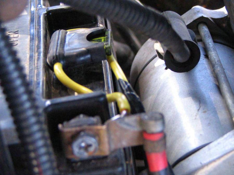
6 In this picture, you will notice another coupler attach to the R/R coupler. On this coupler, there are black 3 wires coming from inside the left chrome cover. These 3 black wires are directly from the Stator. Disconnect this coupler with the 3 Black wires from the Stator. On the coupler that was connected to the R/R coupler, cut the Red and B/W wire right at the R/R coupler and leave them hang for now.

7 Cut all 3 black wires as close as possible to the Stator coupler.

8 Strip approximately ¾ inch of insulation of each of the 3 black wires. Be careful when stripping the three black wires not to cut any of the wire strands.

9 Remove the coupler from the R/R as close as possible to it.

10 Position the R/R on the front battery cover, notice the amount of spacing from the bottom of the cover and use a center punch to mark the location of the holes to be drilled. Make sure that you have a block of steel or piece of wood lined up on the backside of the cover so it won t bend when striking the center punch. Use two screws, lock washers and nuts to secure the R/R to the battery cover making sure the head of the bolts will not make contact with the battery. Note: If the R/R is too low on the cover and your shock spring are weak, the tip of the fender could make contact with it when riding over a bump or pothole.
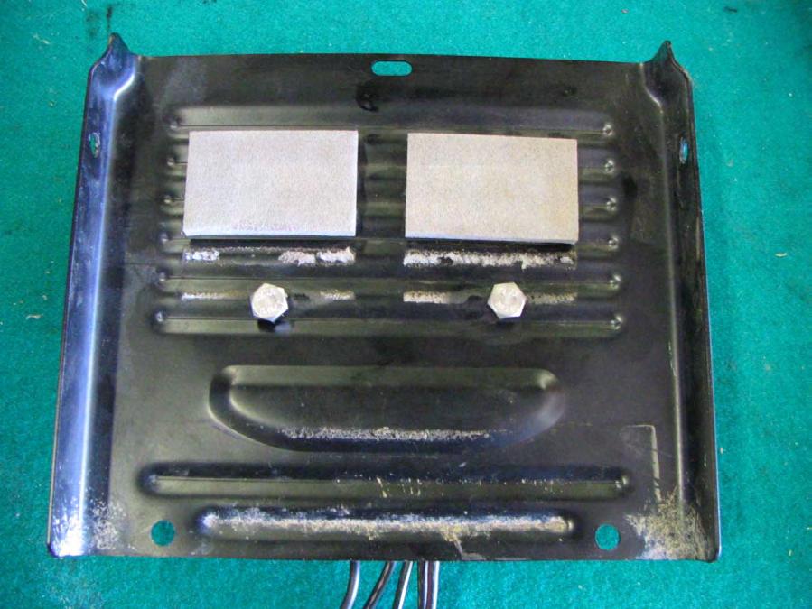
11

12 Mount the battery cover back in position.

13 Next, you will need to connect the 3 Black wires from the R/R to the new Stator extension cord. Cut the extension cord, strip the outer insulation and solder them and insulate each one of them. I staggered them to minimize the bulkiness.

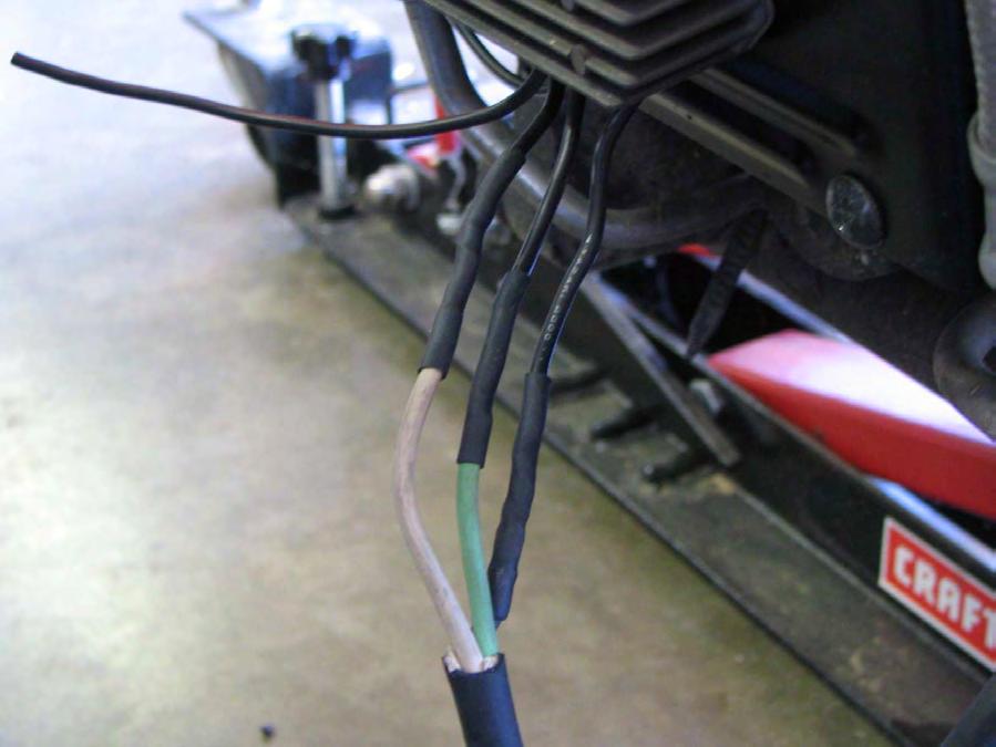
14

15 Next step will be to extend the positive(s) and negative (-) wires from the R/R so they may reach the battery terminals. Cut approximately 1 foot from the 4-foot extension cord. Strip the outer insulation and use the black wire and white wire to extend the positive and negative wires from the R/R. You can use the white wire and solder it to the Black with Red tracer wire (+) from the R/R. You can also cover it up with shrink tube or electrical tape to give it added protection and insulation. Solder the black wire to the Black with White tracer wire (-).

16 Take the inline fuse holder and solder an eyelet terminal to one end of it. Solder the other end of the fuse holder to the extended wire you just installed from the Black wire with Red tracer making sure that it will long enough to reach the positive battery terminal. Insert the 30-amp fuse in the holder and fasten it to the positive terminal of the battery using the eyelet you installed and place it on top of the battery.
17

18 Run the wire from the fuse holder that you just installed and run it down following positive cable from the battery and secure it with a few straps. Do the same for the B/W wire(s) from the R/R and connect to the negative side of the battery once you have completed all of the connections.

19 Once all wires are insulated, take the extension cord and follow the frame towards the chrome cover where the R/R was located and follow the wire which comes from the side stand switch which you will see in the next pictures. Once you have the extension cord in position, secure it under the battery box using a strap.

20

21 Leave yourself about 5-6 inches of cord so you will have no problems working with them. Strip all three wires so they could be soldered onto the 3-stator wires that you have already stripped. There is no matching or pairing up involved when soldering the Stator wires onto the extension cord wires. You could use shrink tubes or electrical tape to insulate each of the 3 wires.

22 Once they are all insulated, wrap it all up.

23 Strip the B/W wire that you already cut off from the R/R coupler and install one eyelet terminal on the B/W wire. The Red wire will no longer be used. Insulate the Red wire so it won t short out anywhere.

24 Remove the right hand side hold down bolt on the clutch slave cylinder and install the B/W wire with the eyelet terminal you installed and tighten.

25 Once you are done these steps, secure all of the wires using the OEM secure clamps and run the newly install Stator extension wire downwards on the left side of the slave cylinder, secure it with a few tie straps and follow the frame towards the battery.
26 I do recommend that you install a high quality permanent voltmeter on your bike so you may keep an eye on your charging system as you ride. Total time to do this modification is between 2-3 hrs. O.C.D.
Disconnect the negative battery cable!
 Understanding Mod-3 on a C90 With Wiring Diagrams By DrJones18LC I do not have a C90 at my disposal (or audio/video equipment for that matter) so I can't make a live step by step how-to on doing Mod-3.
In This DIY We Will Show You How To Install Recon Backup Lamps (part # To Run On A Separate Switch & In Reverse.
 In This DIY We Will Show You How To Install Recon Backup Lamps (part # 264150 To Run On A Separate Switch & In Reverse. Please Note, There Are Many Ways of Installing These Lights, Including Wiring Methods,
Amp & Speaker Upgrade Install Instructions for Victory Cross Country
 Amp & Speaker Upgrade Install Instructions for Victory Cross Country Tools Needed: 13mm Socket 4mm Ball Head Allen Socket 5mm Allen Wrench 10mm Wrench Wire Cutters Wire Strippers Phillips Screwdriver Pocket
SCION xb PERFORMANCE AIR INTAKE Section I Installation Preparation 2.4L I-4
 Section I Installation Preparation 2.4L I-4 Part Number(s): PTR03-52110 Kit Contents Item # Quantity Description Reqd. 1 1 TRD Inlet Tube 2 1 TRD Upper Air Box with HC Trap 3 1 Hump Hose Coupler 4 1 Hump
INSTALLATION INSTRUCTIONS
 Rear Vision System Tailgate Handle Camera Mirror Display 2004-2014 Ford F-150 and 2008-2015 Ford Super Duty (Kit part numbers 9002-9521) Kit Contents: Mirror Tailgate Handle with camera and harness Interior
750 Paso Wiring Upgrade
 750 Paso Wiring Upgrade Supplies required: 2 Bosch 30A/12V Relays # #0 332 209 150 (with mounting tab) 1 30 Amp fuse holder 1 10 Amp fuse holder 12 inches of brown 12 gauge wire 60 inches of red 14 gauge
2013 Road King CVO FLHRSE5 Detachable Fairing w/ Garmin Zumo 665 Installation Instructions
 2013 Road King CVO FLHRSE5 Detachable Fairing w/ Garmin Zumo 665 Installation Instructions 1 1. Turn ignition switch to on position and leave there. This will prevent alarm from going off when you disconnect
Ford Racing 4.6L 3V Crate Engine Control Pack
 Ford Racing 4.6L 3V Crate Engine Control Pack Installation Time: 3-6 hours on a Foxbody Mustang Tools Required: Basic English and Metric Socket and Wrench Set Flat and Phillips Screwdrivers Torx bits Hammer
INSTALLATION INSTRUCTIONS
 Rear Vision System Tailgate Emblem Camera Mirror Display 2009-Current Ford F-150 and 2010-Current Super Duty (Kit part number 1008-9527) Kit Contents: Mirror Tailgate Emblem Mount with Camera Interior
CERTAIN TRANSIT VEHICLES EQUIPPED WITH A TRAILER MODULE TRAILER MODULE FUSE AND FOOTWELL DRAINAGE HOLE
 PAGE 1 OF 19 CERTAIN 2015-2017 TRANSIT VEHICLES EQUIPPED WITH A TRAILER MODULE TRAILER MODULE FUSE AND FOOTWELL DRAINAGE HOLE OVERVIEW In the affected vehicles, it may be possible for water to pool and
SPEED CONTROL 4 AND 6 CYL. JEEP WRANGLER. Read entire instructions thoroughly before starting. INSTALLATION INSTRUCTIONS TOOLS REQUIRED:
 Read entire instructions thoroughly before starting. TOOLS REQUIRED: SPEED CONTROL 4 AND 6 CYL. JEEP WRANGLER INSTALLATION INSTRUCTIONS Complete socket set Phillips screwdriver Torx drivers Wire strippers/cutters
Airtail I.A.S. Suspension System for Harley Davidson
 5572 Fresca Drive, La Palma, CA 90623 714.523.8700, FAX 714.523.3220 Airtail I.A.S. Suspension System for Harley Davidson Compressor Kit Installation Instructions FLH/FLT Models with and without Cruise
FOG-LAMPS INSTALL KIT
 FOG-LAMPS INSTALL KIT DODGE RAM (BR, BE) Installation Instructions Read entire instructions thoroughly before starting. For proper removal and installation, follow procedures in the service manual. NOTES:
Mableaudio Company limited
 Mableaudio Company limited Web: www.mableaudio.com [5E3 assembly manual] Tel:0086-755-83996326 fax:0086-755-83996326 Contact: Ms Mable mable@mableaudio.com WARNING! This amp operates at voltages that may
Your Legal Fuel Tank Source.
 February 23, 2015 IS# 808 Page 1 of 13 THANK YOU FOR PURCHASING A TRANSFER FLOW 40 GALLON TOOLBOX REFUELING SYSTEM. PLEASE READ THE FOLLOWING PROCEDURES CAREFULLY BEFORE STARTING THE INSTALLATION. CAUTION:
Handyman Motor Capacitor Meter PART NO
 Handyman Motor Capacitor Meter PART NO. 2225174 To test a motor-run capacitor in the field with no capacitance meter at hand, you had to hook up the capacitor through an extension cable to a 120V wall
FOG LAMPS INSTALL KIT
 FOG LAMPS INSTALL KIT PT CRUISER INSTALLATION INSTRUCTIONS Read entire instructions thoroughly before starting. For proper aiming of fog lamps, follow procedures in the service manual. NOTES: Left and
Installing Ignition Coil relay
 Installing Ignition Coil relay Above is a schematic diagram of the coil relay modification. All it really does is, it uses the existing 12 Volt positive that normally powers the coils, to power a relay,
SPEED CONTROL 4 AND 6 CYL. JEEP WRANGLER. Read entire instructions thoroughly before starting. INSTALLATION INSTRUCTIONS TOOLS REQUIRED:
 Read entire instructions thoroughly before starting. TOOLS REQUIRED: SPEED CONTROL 4 AND 6 CYL. JEEP WRANGLER INSTALLATION INSTRUCTIONS Complete socket set Phillips screwdriver Torx drivers Wire strippers/cutters
Mustang Headlight w/ CCFL Halo (05-09) - Installation Instructions
 - Installation Instructions") Mustang Headlight w/ CCFL Halo (05-09) - Installation Instructions The below installation instructions work for the following products: Chrome Mustang Headlight w/ CCFL Halo (05-09) Smoked Mustang Headlight
Mustang Headlight w/ CCFL Halo (05-09) - Installation Instructions The below installation instructions work for the following products: Chrome Mustang Headlight w/ CCFL Halo (05-09) Smoked Mustang Headlight
A selection of phillips head screwdrivers 15mm socket 10mm socket Modeler s knife Solder Electrical tape A selection of flat head screwdrivers
 Read entire instructions thoroughly before starting. References to the service manual wiring diagrams and operation sections will be required for adjustments, fastener torques, and troubleshooting. TOOLS
CVO - with ipod Amp & Speaker Upgrade Install Instructions for Batwing Fairing
 CVO - with ipod Amp & Speaker Upgrade Install Instructions for Batwing Fairing Tools Needed: 1/2 inch Socket Wire Cutters 7/16 inch Socket Wire Strippers 5/16 inch Socket Phillips Screwdriver 1/2 inch
INSTALLATION INSTRUCTIONS FUEL SURGE TANK KIT
 INSTALLATION INSTRUCTIONS FUEL SURGE TANK KIT BMW E46 3-Series, Excl Convertible Document: 19-0056 Support: info@radiumauto.com Relieve fuel pressure in vehicle before beginingthe installation. Disconnect
INSTALLATION INSTRUCTIONS
 INSTALLATION INSTRUCTIONS Accessory Application Publications No. SYSTEM 2005 ACCORD All 27511 (DX, LX) 2-AND 4-DOOR Issue Date AUG 2004 PARTS LIST Security System Attachment (LX): P/N 08E55-SDA-100A Unit
Ford 6.7L Installation of the Guardian Safety System
 Ford 6.7L Installation of the Guardian Safety System Diesel Tech Industries Ltd. 14215-120 Avenue Edmonton, Alberta, Canada T5L 2R8 Phone: (780) 455-9876 info@dtiguardian.com www.dtiguardian.com DTI05-02.01/13
INSTALLATION INSTRUCTIONS
 Rear Vision System Liftgate Emblem Camera Mirror Display 2009-2012 Ford Flex (Kit part number 1008-9527) Kit Contents: Mirror Liftgate Emblem Mount with Camera Interior (shorter) Harness Chassis (longer)
TOYOTA SIENNA TRAILER WIRE HARNESS Preparation
 Preparation Part Number: PT791-08150 (non-se) PT791-08102 (SE only) Kit Contents Item # Quantity Reqd. Description 1 1 Trailer Module Harness 2 1 4-Flat Harness 3 1 Battery Power Wire Harness 4 1 Mounting
Installation Instructions for Key Switch SNOWRATOR
 2017 Installation Instructions for Key Switch SNOWRATOR We appreciate your purchase of L.T. Rich s Product. Please read carefully before Operating or detaching. AES L.T.RICH 6/15/2017 SHIPPING CONTENTS...
Amp & Speaker Upgrade Install Instructions for Batwing Fairing
 Amp & Speaker Upgrade Install Instructions for Batwing Fairing Tools Needed: 1/2 inch Socket Wire Cutters 7/16 inch Socket Wire Strippers 10 mm Socket Phillips Screwdriver 1/2 inch Ratchet Wrench T25 Torx
2017 Current Ford Raptor Bump Stop Kit Installation Instructions
 2017 Current Ford Raptor Bump Stop Kit Installation Instructions PREPARATION 1. Disconnect the negative terminal on the battery. Park the vehicle on level ground and set the emergency brake. 2. We recommend
TOYOTA VENZA 2009 TRAILER WIRE HARNESS Procedure
 Part Number: PT791-0T099 Kit Contents Item # Quantity Reqd. Description 1 1 Trailer Wire Harness Module 2 1 4-Flat Harness 3 1 Battery Power Wire Harness 4 1 Mounting Bracket, 4-Flat 5 2 Screw #10-24 6
Installation Manual Lock-Switch KIA Sorento V3 Installation Manual Lock-Switch V3 for KIA Sorento (02-06) and KIA Sorento (07-09)
 and KIA Sorento (07-09)") Installation Manual Lock-Switch V3 for KIA Sorento (02-06) and KIA Sorento (07-09) Note: A any work on the electrical system of a car before should the battery be disconnected at the negative terminal
Installation Manual Lock-Switch V3 for KIA Sorento (02-06) and KIA Sorento (07-09) Note: A any work on the electrical system of a car before should the battery be disconnected at the negative terminal
INSTALLATION INSTRUCTIONS
 Rear Vision System Tailgate Emblem Camera Aftermarket Display 2009-Current Ford F-150 and 2010-Current Super Duty (Kit part number 1008-6509) Kit Contents: Tailgate Emblem Mount with Camera Chassis Harness
 INSTALLATION INSTRUCTIONS Accessory ACCESSORY HANDSFREELINK (WITH MOON) Application 2009 PILOT Publications No. AII 39492 Issue Date MAY 2008 PARTS LIST HFL Attachment Kit 2 Washer screws, 4 x 12 mm HFL
X-Type w/ non-premium sound amplifier installation instructions
 X-Type w/ non-premium sound amplifier installation instructions 1. Pull radio from dash (see Radio Removal Instructions ) 2. Disconnect wiring harness from back of radio by pushing in tab on plug and pulling
INSTALLATION INSTRUCTIONS
 INSTALLATION INSTRUCTIONS Accessory S Application 2011 PILOT Publications No. AII 43298 Issue Date MARCH 2010 PARTS LIST Back-up Sensor Attachment Kit P/N 08V67-SZA-100A Back-up sensor harness Fuse label
Dodge Cummins Positive Air Shutoff
 1 INSTALL MANUAL 2010-2012 6.7 Dodge Cummins Positive Air Shutoff P/N# 1036722 P/N# 1036722-M UPLEASE READ ALL INSTRUCTIONS BEFORE INSTALLATION An Information decal has been provided in this kit. This
Magnuson Intercooler Relocation
 Magnuson Intercooler Relocation Please read these instructions all the way through before beginning the installation. Doing so will definitely save you some rework. Although this installation can be accomplished
INSTALLATION INSTRUCTIONS
 INSTALLATION INSTRUCTIONS Accessory Application Publications No. AII 24307 SYSTEM 2003 ELEMENT Issue Date DEC 2002 NOTE: An optional keyless entry system (sold seperately) must be installed before you
MachoMan Moped Assembly Instructions. If you have no mechanical experience, please have the unit professionally assembled.
 MachoMan Moped Assembly Instructions If you have no mechanical experience, please have the unit professionally assembled. Tools needed: #2 Phillips Screwdriver, 14mm Socket, 12mm Socket, 10mm Socket, 14mm
TOYOTA VENZA 2009 TRAILER WIRE HARNESS Procedure
 Part Number: PT791-0T099 Kit Contents Item # Quantity Reqd. Description 1 1 Trailer Wire Harness Module 2 1 4-Flat Harness 3 1 Battery Power Wire Harness 4 1 Mounting Bracket, 4-Flat 5 2 Screw #10-24 6
PRELIMINARY INSTALLATION INSTRUCTIONS. PARTS LIST Security System Kit (sold separately) P/N 08E51-EP4-101
 P/N 08E51-EP4-101") INSTALLATION INSTRUCTIONS Accessory Application Publications No. All 30510 (LX) 2006 PILOT Issue Date SEP 2005 PARTS LIST Security System Kit (sold separately) P/N 08E51-EP4-101 Security system control
INSTALLATION INSTRUCTIONS Accessory Application Publications No. All 30510 (LX) 2006 PILOT Issue Date SEP 2005 PARTS LIST Security System Kit (sold separately) P/N 08E51-EP4-101 Security system control
UD Sub Box- Parts List
 UD Sub Box- Parts List 1 UD Sub Box 1 Flex Bracket 1 Wire Tie 2 7/16 Nuts 2 Lock Washers 2 Washers 2 Screws 1 Installation Guide 1 6.5 Subwoofer (optional) We highly recommend a professional install the
INSTALLATION INSTRUCTIONS FOR THE TOMAHAWK ELECTRIC REVERSE
 INSTALLATION INSTRUCTIONS FOR THE TOMAHAWK ELECTRIC REVERSE LAST UPDATED: April 2018 Thank you for choosing the Motor Trike Electric Reverse. We ask that you read the directions before you start and follow
Installation MKIV Headlight Housings with Fog Lamps (Procedures apply to both MKIV Jetta and Golf)
") Page 1 This tutorial is provided as a courtesy by ECS Tuning. Service Procedure Installation Proper service and repair procedures are vital to the safe, reliable operation of all motor vehicles as well
Page 1 This tutorial is provided as a courtesy by ECS Tuning. Service Procedure Installation Proper service and repair procedures are vital to the safe, reliable operation of all motor vehicles as well
CHARGING SYSTEM 7.7 GENERAL TROUBLESHOOTING. Alternator. Voltage Regulator. Battery. Wiring. Voltage Regulator Inspection HOME
 CHARGING SYSTEM 7.7 GENERAL 8740 The charging system consists of the alternator and regulator. Charging system circuits are shown in Figure 7-5. Never install accessory wiring between battery post and
How To: Convert Headlight DRLs Into Marker DRLs A CFans Members Mod Project by burn
 How To: Convert Headlight DRLs Into Marker DRLs A CFans Members Mod Project by burn Skill Level: Easy Disclaimer: Please use caution and seek professional assistance when necessary. ColoradoFans.com, the
Installation Instructions 1812 Folder Disk Clutch Retrofit Kit Martin Yale #WRA
 Installation Instructions 1812 Folder Disk Clutch Retrofit Kit Martin Yale #WRA1812510 Background: Early production Martin Yale Model 1812 Folders were originally equipped with a spring-clutch type feed
Progressive Suspension Airtail I.A.S.
 5572 Fresca Drive, La Palma, CA 90623 714.523.8700, FAX 714.523.3220 Progressive Suspension Airtail I.A.S. Installation Instructions for Harley Davidson E.C.C. with Compressor Kit FLH/FLT Models with and
Step #1 From your spool of 18 gauge primary wire, cut between 11 and 21 three inch strips of wire. You will only need 11 for the ROV, but it is good t
 How to make a ROV! Step #1 From your spool of 18 gauge primary wire, cut between 11 and 21 three inch strips of wire. You will only need 11 for the ROV, but it is good to have extras. Using the wire cutter,
Installation Instructions QUICKSILVER CONSOLE SHIFTER Fits: Chevelle / El Camino
 WORK SAFELY! For maximum safety, perform this installation on a clean, level surface and with the engine turned off. Place blocks or wedges in front of and behind both rear wheels to prevent movement in
06-15 ECU, Battery and Washer Bottle Relocation
 06-15 ECU, Battery and Washer Bottle Relocation On the 2006-2015 MX-5, there is a very narrow middle section between the battery box and the air filter box to remove heat. For the most part, this design
20 Rigid Industries LED Light Bar Installation into a 2002 Ford Super Duty
 20 Rigid Industries LED Light Bar Installation into a 2002 Ford Super Duty This write-up is how I installed the Rigid Industries 20" E-Series LED Light Bar into the grill area behind the license plate
Important: Please read these instructions carefully and completely before starting the installation. TITAN Fuel Tanks INSTALLATION GUIDE
 TITAN pt. no.: 03 0000 0128 Important: Please read these instructions carefully and completely before starting the installation. TITAN Fuel Tanks INSTALLATION GUIDE 30 Gallon* Spare Tire Auxiliary Fuel
2015 Mustang Lightbar (All Models) CDC#
 CDC#") 2015 Mustang Lightbar (All Models) CDC# 1511-7000-01 Components: 1 CDC Lightbar Note: READ instructions before starting installation!!! CDC Part# Driver side bracket 0511-6001-05 Passenger side bracket
2015 Mustang Lightbar (All Models) CDC# 1511-7000-01 Components: 1 CDC Lightbar Note: READ instructions before starting installation!!! CDC Part# Driver side bracket 0511-6001-05 Passenger side bracket
INSTALLATION INSTRUCTIONS
 INSTALLATION INSTRUCTIONS Accessory Application Publications No. P/N 08E49-S2A-100 2004 S2000 AII 26325 Issue Date OCT 2003 PARTS LIST Hood switch harness TOOLS AND SUPPLIES REQUIRED #2 Phillips screwdriver
Dodge Ram Quad Cab A Dodge Ram Quad Cab 2500/ A Dodge Ram Mega Cab A
 INSTALLATION GUIDE APPLICATION MODEL YR AMP PART # Dodge Ram Quad Cab 1500 2002-2008 5101-01A Dodge Ram Quad Cab 2500/3500 2003-2009 5101-01A Dodge Ram Mega Cab 2006-2009 5118-01A INSTALLATION TIME 3-5
INSTALLATION INSTRUCTIONS
 OEM Tailgate Camera/Bezel Assembly with Chassis Harness 2014-current Chevrolet Silverado and GMC Sierra (Kit part number 9002-1005) Kit Contents: Chassis Harness 1 bubble bag containing: Tailgate Handle
SCION xd INTERIOR LIGHTING UPGRADE Preparation
 Preparation Part Number: PTS21-52085 Light Guide Kit Contents Item # Quantity Reqd. Description 1 1 Controller Board, 4 color programmed w/ Bracket 2 1 RGB, LED Engine wire harness 3 2 14mm Light Rod,
INSTALLATION INSTRUCTIONS
 INSTALLATION INSTRUCTIONS Honda Dealer: Please give a copy of these instructions to your customer. PARTS LIST (15) (8) (12) (14) (13) (10) (11) (18) (17) (1) Accessory Application Publications No. TRX500FA/FGA
INSTALLATION INSTRUCTIONS
 INSTALLATION INSTRUCTIONS Accessory Application Publications No. AII 26320 ATTACHMENT KIT 2004 S2000 Issue Date OCT 2003 PARTS LIST CD Changer Attachment Kit: P/N 08B26-S2A-100A Plain washer Template CD
INSTALLATION INSTRUCTIONS
 INSTALLATION INSTRUCTIONS Accessory Accessory Hands Free Link Application 2008 ACCORD 2 AND 4-DOOR Publications No. AII 38281 Issue Date NOV 2007 PARTS LIST Attachment Kit P/N 08E02-TA0-100 trim retainer
INSTALLATION INSTRUCTIONS
 INSTALLATION INSTRUCTIONS PARTS LIST Accessory Application Publications No. TRX420 (All) MII 13032 WINCH KIT P/N 08L94-HP5-100 Accessory Weight 35 lbs (16 kg) Honda Dealer: Please give a copy of these
Model 377, 379, 386, 388, Sleeper no window
 Installation Manual Model 377, 379, 386, 388, 389 63 Sleeper no window 2390 Blackhawk Road P.O. Box 6007 Rockford, IL 61125 www.nitesystem.com 1-866-204-8570 NITE Plus Installation Procedures 1-2 Table
MUSTANG GT
 MAXFLOW FUEL PUMP BOOSTER Installation Instructions 2011-2012 MUSTANG GT P/N: 5A102-029 ENGINEERING, INC. 1650 Pacific Avenue, Channel Islands, CA 93033-9901 Phone 805 247-0226 Fax: 805 247-0669 www.vortechsuperchargers.com
INSTALLATION INSTRUCTIONS
 INSTALLATION INSTRUCTIONS Accessory REAR SPOILER Application 2011 CR-Z MUGEN Publications No. AII 45919 Issue Date APRIL 2011 PARTS LIST Right wing bracket Rear wing Left wing bracket Right wing base Right
INSTALLATION INSTRUCTIONS
 INSTALLATION INSTRUCTIONS Accessory Application Publications No. BII 31129 REARVIEW CAMERA 2006 RL Issue Date OCT 2005 PARTS LIST Attachment Kit P/N: 08B21-SJA-B00 Template Rear camera trim 6-Pin connector
Honda Pioneer 1000 Turn Indicator Kit
 Honda Pioneer 1000 Turn Indicator Kit Thank you for purchasing XTC Power Products Turn Signal System. Our Turn System is unique from the other kits on the market. Our Kit is plug and play with only power
SUT-250-S (These instructions are used for SUT-250-SCLC also)
") SUT-250-S (These instructions are used for SUT-250-SCLC also) Torque wrench, carpenters square, wire cutters, Phillips screwdriver, 7/16, 9/16, and 3/4 combination wrenches, ratchet, 9/16, 3/4, 13/16,
SUT-250-S (These instructions are used for SUT-250-SCLC also) Torque wrench, carpenters square, wire cutters, Phillips screwdriver, 7/16, 9/16, and 3/4 combination wrenches, ratchet, 9/16, 3/4, 13/16,
INSTALLATION INSTRUCTIONS
 INSTALLATION INSTRUCTIONS Accessory Application Publications No. REMOTE CONTROL 2009 MDX BII 40030 Issue Date JULY 2008 PARTS LIST Remote Engine Starter Unit Kit P/N 08E91-E22-200B Remote Control Engine
INSTALLATION INSTRUCTIONS
 INSTALLATION INSTRUCTIONS Accessory Application Publications No. BII 39890 2009 MDX Issue Date JULY 2008 PARTS LIST Backup Sensor Attachment Kit P/N 08V67-STX-200A Self-tapping screw, 5 x 16 mm 12 Wire
Page 1 of 1 ALTERNATORS. Overview. Intek TM V-Twin Cylinder OHV Engine Service Manual Version 1.0. Copyright 1999 by Briggs and Stratton Corporation
 Overview Alternator Identification Page 1 of 3 The alternator systems installed on Briggs & Stratton Intek V-Twin Cylinder OHV Engines can easily be identified by the color of the stator output wires and
SWING DOOR SOFT ENCLOSURE (part# 16733)
") 800-643-7332 americanlandmaster.com This kit is for use with all fullsize, 2 passenger ALM utility vehicles. SWING DOOR SOFT ENCLOSURE (part# 16733) NOTE TOOLS REQUIRED Drill 1/4 Drill Bit 7/16 Wrench
800-643-7332 americanlandmaster.com This kit is for use with all fullsize, 2 passenger ALM utility vehicles. SWING DOOR SOFT ENCLOSURE (part# 16733) NOTE TOOLS REQUIRED Drill 1/4 Drill Bit 7/16 Wrench
Ford 6.7L Powerstroke Positive Air Shutoff
 8 April 2013 Ford 6.7L 2011-2012 Positive Air Shutoff 1 2011-2012 Ford 6.7L Powerstroke Positive Air Shutoff P/N# 1036703 P/N# 1036703-M UPLEASE READ ALL INSTRUCTIONS BEFORE INSTALLATION BD Engine Brake
INSTALLATION GUIDE. TECH SUPPORT Monday - Friday, 8:00 AM - 5:00 PM PST
 INSTALLATION GUIDE APPLICATION LENGTH MODEL YR PART # Ford Super Duty F-250 / F-350 Regular Cab ( ) 1999 200 10-02513-2 Ford Super Duty F-250 / F-350 Super Cab (5 ) 1999 200 10-02513-25 Ford Super Duty
Instructions for Yamaha G14/G16/G19/G22 Models
 Instructions for Yamaha G14/G16/G19/G22 Models The Light Kit includes: (31483) Brakelight Connector Turn Signal Connector (1) Main Wire Harness with Positive & Negative In-line Fuses. (1) Head Light Switch.
INSTALLATION INSTRUCTIONS
 INSTALLATION INSTRUCTIONS Accessory Application 2012 ZDX Publications No. BII 47089 Issue Date SEP 2011 PARTS LIST Tailgate spoiler 2 Brackets 4 Nuts 4 Bolts TOOLS AND SUPPLIES REQUIRED Phillips screwdriver
* * Inside Toyota Avalon. Tools Required IMPORTANT
 Revision 08/02/16 2013- Toyota Avalon IMPORTANT Before starting, compare items on your invoice with items received. Carefully check through packaging material. If any item is missing, please call Crutchfield
Ford F150 SuperCab Ford F150 SuperCrew
 INSTALLATION GUIDE APPLICATION LENGTH MODEL YR PART # Ford F150 SuperCab 7 00-007 10-0996-11 Ford F150 SuperCrew 79 00-007 10-0996-1 INSTALLATION TIME 3:00 hrs SKILL LEVEL 1 3 = Experienced TOOLS REQUIRED
TOYOTA RAV TRAILER WIRE HARNESS Preparation
 Preparation Part Number: PU322-42013-UW Kit Contents Item # Qty Description 1 1 Trailer Module Harness 2 1 Trailer 4-Flat Harness 3 1 Trailer Power Wire Harness 4 1 Mounting Bracket, 4-Flat 5 2 Screw #10-24
Model A Turn Signal Kit Installation Guide
 Model A Turn Signal Kit Installation Guide Creative Connections, Inc. Consumer Hot Line: 888-471-LOGO 770-476-7322 In Atlanta, GA http://www.logolites.com P/N: 100-005/K 2008 Creative Connections, Inc.
L/6.7L DODGE CUMMINS
 10/19/2012 2005-08 5.9/6.7 Dodge Cummins FlowMAX Lift Pump Kit # 1050310B - 1-2005-09 5.9L/6.7L DODGE CUMMINS BD FLOWMax V2 LIFT PUMP KIT Installation Instructions P/N # 1050310B PLEASE READ ALL INSTRUCTIONS
SUT-450-I ASSEMBLY REQUIREMENTS
 SUT-450-I Torque wrench, carpenters square, wire cutters, Phillips screwdriver, 7/16, 9/16, and 3/4 combination wrenches, ratchet, 9/16,3/4,13/16, and 7/8 sockets. ASSEMBLY REQUIREMENTS *Torque all T-bolt
JEEVES. JEEVES Installation Manual. Installation Manual The Easiest Do-It-Yourself Dumbwaiter on the Market
 1 888-323-8755 www.nwlifts.com JEEVES Installation Manual The Easiest Do-It-Yourself Dumbwaiter on the Market This manual will cover the installation procedure step-by-step. The installation of this dumbwaiter
INSTALLATION INSTRUCTIONS
 INSTALLATION INSTRUCTIONS Accessory REMOTE ENGINE STARTER SYSTEM Application 2010 CIVIC 4-DOOR Publications No. AII 42460 Issue Date AUG 2009 PARTS LIST Remote Engine Starter Unit Kit P/N 08E91-E22-100B
Table No. 1 provides a means of identifying the various alternator systems. Note: All output figures are rated at 3600 RPM. TABLE NO.
 The alternator systems installed on Briggs & Stratton Intek OHV-Twin Cylinder Engines can easily be identified by the color of the stator output wires and the connector. Table No. 1 provides a means of
Toyota Tacoma Double Cab up A Toyota Tacoma Access Cab* up A. 3-5 Hours INSTALLATION GUIDE INSTALLATION TIME SKILL LEVEL
 INSTALLATION GUIDE APPLICATION MODEL YR PART # Toyota Tacoma Double Cab 2005 - up 75142-01A Toyota Tacoma Access Cab* 2005 - up 75142-01A INSTALLATION TIME 3-5 Hours Professional installation recommended
 Page 1 of 14 This install requires work on your supplemental restraint system and could cause injury or damage to your car. If you are not comfortable performing the steps detailed here then do not attempt
LiteDOT Installation Document
 LiteDOT Installation Document This document designed to aid in installation of LiteDOT s on Jeep TJ models, other models are similar. NOTE: Installing LiteDOT s on a Jeep where the 2 necessary mounting
PRELIMINARY INSTALLATION INSTRUCTIONS. Remote Engine Starter Attachment Kit P/N 08E92-SNA-100B
 INSTALLATION INSTRUCTIONS Accessory Application Publications No. REMOTE ENGINE STARTER SYSTEM 2008 CIVIC 2-DOOR AII 38215 Issue Date OCT 2007 PARTS LIST Remote Engine Starter Unit Kit P/N 08E91-E22-100B
xtablet T7000 Vehicle Mount Kit
 xtablet T7000 Vehicle Mount Kit Installation & Users Guide Last Updated: January 19, 2012 Find the latest updates in the Support section in the MobileDemand website at: www.ruggedtabletpc.com. Questions?
Installation Instructions for Lingenfelter GM 2500 Suburban & Yukon XL Auxiliary Fan System (with AC clutch controlled fan output)
") Installation Instructions for Lingenfelter 2007-2013 GM 2500 Suburban & Yukon XL Auxiliary Fan System (with AC clutch controlled fan output) PN L300080607 Revision - 1.1 Lingenfelter Performance Engineering
Installation Instructions for Lingenfelter 2007-2013 GM 2500 Suburban & Yukon XL Auxiliary Fan System (with AC clutch controlled fan output) PN L300080607 Revision - 1.1 Lingenfelter Performance Engineering
½ DODGE CUMMINS
 7 April 2009 2003-04½ Dodge Cummins FlowMAX Lift Pump Kit # 1050305-1 - 2003-04½ DODGE CUMMINS BD FlowMax LIFT PUMP KIT Installation Instructions P/N# 1050305 PLEASE READ ALL INSTRUCTIONS CAREFULLY BEFORE
 INSTALLATION INSTRUCTIONS Accessory Application Publications No. AII 33173 UNDER 2007 ODYSSEY Issue Date JULY 2006 PART LIST Front under spoiler 5 Stepped bolts TOOLS AND SUPPLIES REQUIRED Phillips screwdriver
INSTALLATION INSTRUCTIONS
 Rear Vision System Mirror Display 2004 onwards Ford F-150 and 2008 onwards Ford Super Duty (Kit part numbers 1008-9520 and 1008-9525) Kit Contents: RVS Interior (shorter) Harness RVS Chassis (longer) Harness
INSTALLATION INSTRUCTIONS
 INSTALLATION INSTRUCTIONS Accessory Application Publications No. All 30482 S 2006 PILOT Issue Date P/N 08F23-S9V-100A SEP 2005 PARTS LIST Left front trim piece Right front trim piece Left rear trim piece
PRELIMINARY INSTALLATION INSTRUCTIONS. PARTS LIST Left front trim piece
 INSTALLATION INSTRUCTIONS Accessory Application Publications No. All 30482 S 2006 PILOT Issue Date P/N 08F23-S9V-100A SEP 2005 PARTS LIST Left front trim piece Right front trim piece Left rear trim piece
TRAIL CHARGER with EXTENDER and COMBO NOSE BOX
 TRAIL CHARGER with EXTENDER and COMBO NOSE BOX 284424 01 Version 1.02 03/14/2011 Owners Manual Operation Installation Wiring Diagram Troubleshooting Parts Breakdown 1 GENERAL OPERATION PROBLEM On applications
INSTALLATION INSTRUCTIONS
 INSTALLATION INSTRUCTIONS Accessory Application Publications No. SYSTEM S2000 AII 26324 Issue Date OCT 2004 PARTS LIST Headrest Speaker System P/N 08A54-S2A-100 3 Small wire ties 2 Headrest speakers 9