TTR225/250 DUAL S PORT K IT I NSTALLATION I NSTRUCTIONS
|
|
|
- Anastasia Alexander
- 6 years ago
- Views:
Transcription
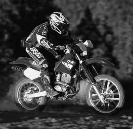
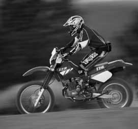
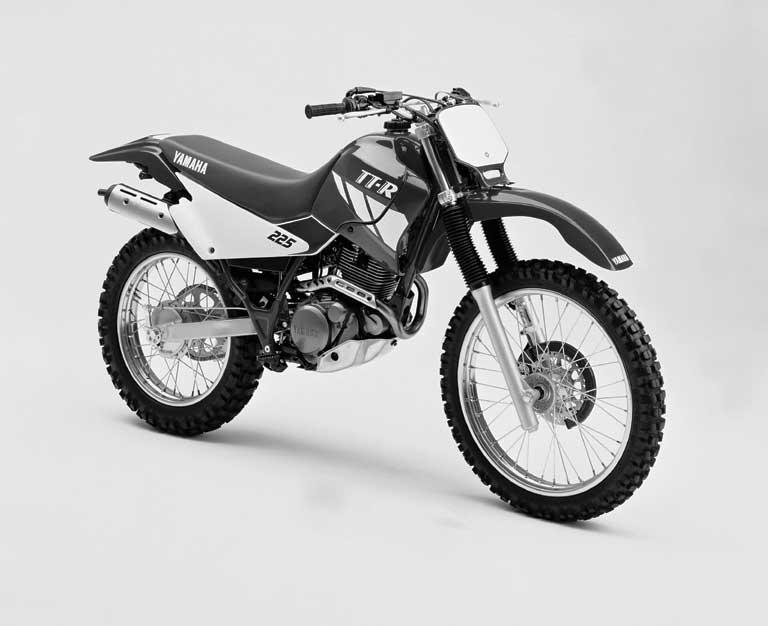
1 TTR225/250 DUAL S PORT K IT I NSTALLATION I NSTRUCTIONS
2 KIT CONTENTS Inspect Your Kit Your kit will include the following items A. TTR225/250 Instructions and Wiring Diagrams Read through the entire instruction manual before starting. B B. Dakar Headlight Assembly A C. Handlebar Turn Switch D. Horn E. Tail Light and Mounting Screws F. Universal Hardware Bag (Contents) C D -Turn Signals (4) -Brake Light Switches (2) E -Cable Ties -Wiring Diagram Label F -Round Plastic Signal Alignment Wedges H G. Main Wiring Harness H. Mounting Kit Hardware Bag -Triple Clamp Mounting Brackets -Kit Specific Pieces Turn Signals Note: If any of the items listed are not included, please take a moment to inspect the hardware bags. Several components are shipped within these bags to ensure complete kit integrity. Also, parts depicted in the hardware bags may not match your kit contents. They are drawn for visual representation only. Note: TTR250 kit does not include a taillight. The OEM unit is used in the installation. TTR225 only uses 1 brake light switch. G Brake Light Switches 1.
3 TAILLIGHT AND TURN SIGNALS F 1/4 Holes E D Remove Existing Parts Remove your existing seat, front number plate, radiator covers, fuel tank, side number plates and rear fender. Please refer to your owners manual for detailed dis-assembly instructions for each item. 1/4 Holes Note: TTR250 kit does not include a taillight. The OEM unit is used in the installation. A B C Taillight Assembly Place the rear fender ( A ) upside down on a clean work surface and position the rear tail light ( B ) on the inside of the fender. The tail light should rest slightly under the rear edge of the fender. I D Note: TTR s may require enlarging the center opening by about 1/2 inch on each side using an electric jig saw. This is for clearance to the existing top brake light. Then, using the rear tail light s four mounting holes ( C ) as guides, trace around each hole with a felt tip marker on the underside of the fender creating drill hole locations. Remove the tail light and drill four 1/4 inch holes. Reposition the tail light, and fasten with supplied screws, washers and nuts ( D ) as shown. J I I E Turn Signal Mounting Step 1 Position the rear turn signals by visually lining up the signals ( G ) behind the rear seat, when its attached to the sub-frame. Care should be observed to insure signals do not interfere with the rear silencer. The signals must mount free and clear of exhaust heat in order to prevent damage to the signal. Once you have found a suitable location for the signal mounting hole ( E ), mark and drill one 3/8 inch hole through each side. G Step 2 Feed the tail light wiring ( I ) through the existing grommet and then the turn signal wiring ( J ). Secure turn signal with supplied alignment wedges, washer and nut ( H ). Attach second turn signal following same procedure and complete by reinstalling rear fender on bike. H Note: Taillight provided for TT-R225 kit may not match illustration. 2.
4 WIRING HARNESS CONNECTION 225 ONLY Routing The Dakar Harness Route the Dakar wiring harness through the clutch lever side of the triple clamps, along the frame extending to the rear fender. Remove The Existing Light Switch Step 1 On the clutch side of the handlebar, you will see the existing light switch. This component needs to be removed Step 2 Un-Plug the YELLOW and ORANGE existing light switch connector. (The Dakar kit features an integrated handlebar signal switch) Existing Wiring Near Ignition Blinker Relay Existing Ignition Switch Connector (RED) Existing Ignition Switch Connector (RED) Existing Ignition Switch Un-Plug the existing ignition switch connector block. Note: It is a WHITE female and RED male connector block. Add The Dakar Connectors Ignition Switch Plug the Dakar male and female ignition into each side of the RED and WHITE existing ignition switch connectors. (This is the one that you just un-connected) Blinker Relay Attach the blinker relay to the frame using a few cable ties around the metal frame tab located slightly above and rearward from the ignition coil. YELLOW and ORANGE Wiring Existing Light Switch (GREEN) Adding The Dakar Harness Blinker Relay (Under Gas Tank) BROWN WHITE Dakar Harness Ground - 3 Ring Terminals NOTE: The Dakar Harness jumpers between the existing RED connection Note: Make sure that the spades on the relay are facing towards the back of the bike. Once the relay has been secured, connect the BROWN and WHITE female spade connectors from the Dakar wiring harness to the existing blinker relay. Ground Connection Remove the existing ground screw to the rectifier mounted next to the blinker relay on the other side of the frame. Then attach the three ring terminals into this ground connection. NOTE: Leave the existing WHITE ignition/kill switch connection alone! Dakar Connector (WHITE) Male Existing Ignition Switch Connector (RED) Existing Ignition Switch Connector (RED) Dakar Connector (WHITE) Female 3.
5 TAILLIGHT AND TURN SIGNAL CONNECTIONS Wiring Decal For reference, stick the wiring connection decal on the rear fender, below where the seat will cover it up. Taillight Connection Step 1 From the existing tail light wiring, dis-connect the YELLOW and BLUE wiring connector. Existing Tail Light Wiring (250 Only) Step 2 Connect the existing BLUE tail light male to the Dakar GRAY female connector and connect the existing male YELLOW to the Dakar dual VIOLET connector. Turn Signal Connections Connect both BLACK tail turn signal grounds into the dual BLACK female ground connector. Connect the ORANGE female into the BLACK male (right turn signal) connector, and the PINK female, into the BLACK male, (left turn signal) connector. Brake Switch Connection (250 Only) Connect one of the BLACK brake switch male leads into the BROWN female connector and the second BLACK brake switch male into the dual VIOLET connector. Route the wiring down along the subframe towards the brake pedal. Note Be sure to carefully and fully seat the connectors into position. Secure Cable Ties Use a few cable ties along the sub frame to hold the harness into position. Make sure that you secure the harness to frame areas that will not bind or crimp the harness. Dakar Harness Existing YELLOW Existing BLUE Rear Tail Light Wiring 4.
6 BRAKE LIGHT SWITCHES Master Cylinder Check Thread Pitch Before Installing WARNING: Check the thread pitch on your banjo bolts Make sure the thread pitch on your stock banjo bolts match the replacement versions provided in the kit. More than likley they will match. Some manufactures have changed the stock design requirement which is why it necessary to check. If your parts do not match up, stop the installation and give us a call. We ll send replacement parts to you! Brake Light Cable Front Brake Light WARNING Bleed front and rear brakes according to instructions provided in your owners or service manual. This must be performed in order for proper brake operation. Failure to do so may result in brake failure Step 1 Place a drop cloth or rag under the front brake and bike to catch any fluids. Loosen and retain banjo bolt on master cylinder. Step 2 Insert brake light switch into position and fasten with banjo bolt on top of soft washer, hydraulic line and second soft washer. Securely fasten banjo bolt without stripping. Step 3 Route the front brake light switch wiring along the lower portion of the handlebar towards the center of the triple clamps. Fasten wiring to the handlebar with a cable tie. Brake Pedal Light Soft Washers Banjo Bolt Banjo Bolt Step 1 Place a drop cloth or rag under the rear brake and bike to catch any brake fluid. Remove the screws and guard providing access to the rear brake master cylinder. You must temporarily reinstall the screws that attach the master cylinder to the frame to prevent damage to the master cylinder or Banjo bolt threads. After the master cylinder is secure, carefully remove the existing banjo bolt. Remove and retain the mounting screws. Brake Light Cable Banjo Bolt Not used on 225 Note: Some bikes allow access to the master cylinder without removing a cover or guard. Step 2 Insert brake light switch into position and fasten with banjo bolt on top of soft washer, hydraulic line and second soft washer. Securely fasten banjo bolt without stripping. Reinstall guard with screws Soft Washers Master Cylinder Fastening Screw 5. Step 3 Route the rear brake light switch wiring up the sub-frame spar and following behind the airbox up towards the back of the frame. The wiring should meet up next to the main wiring harness tail light and turn signal connection point.
7 TURN SWITCH INSTALLATION Remove Existing Kill Switch (250) Note: 225 Existing kill switch and starter button on right side remains. Step 1 Using a small phillips head screwdriver, loosen the locking screw ( B ) on the kill switch ( C ). Remove any cable ties and unplug kill switch from existing wiring. A D Step 2 Loosen clutch cable perch ( D ) and move inboard about 1/2 inch. Install Turn Switch B E C Step 1 Open and wrap the new turn switch ( E ) around handlebar and securely fasten with two screws ( F ) as shown. Step 2 Route turn switch wiring down and along handle bar behind Dakar headlight unit and in through frame cable guide. Secure switch wiring to handlebars with one cable tie. For more information, please refer to the Cable Routing Diagram. Note: 225 Kill button on 225 turn switch is non-operational. Please use existing kill switch on right side to shut engine off. F Cable Tie 6.
8 HEADLIGHT UNIT SUB-ASSEMBLY Existing top triple clamp bolts D F A Existing top triple clamp bolts C B E Headlight Mounting Brackets Remove and retain existing top triple clamp bolts. Position headlight mounting brackets ( A and B ) and loose fit the existing triple clamp bolts at this time. Horn Installation There is a nut ( D ) which is installed on the horn ( C ) mounting stud. Remove nut and locate horn onto mounting tab on right side headlight bracket ( A ) as shown. Make sure the horn s two wiring connection spades face up. Secure horn ( D ) with nut previously removed. Attaching Turn Signals Insert turn signal ( E ) and threaded stud with wiring through headlight bracket turn signal mounting hole. Note: There is a small locator hole directly next to the turn signal mounting hole which is used to position the signal into the headlight bracket. Loose fit, washer and nut ( F ) on signal. Repeat for opposite side. 7.
9 HEADLIGHT WIRING Horn Wiring Headlight Connector From Dakar Wiring Harness LH Signal Wiring RH Signal BLUE RH Signal Wiring Dual Black Signal Ground Connector LH Signal - PINK Handlebar Turn Switch Wiring Connection (Not shown in illustration) Plug-in turn switch wiring harness connector into the main wiring harness white block connector. Be sure to fully seat the connection. You will hear the connector click into position on both the top and bottom sides. Headlight Wiring Connection From the Dakar wiring harness, plug-in the headlight connector into the new headlight assembly. From the Dakar wiring harness, connect the BROWN male lead into the ORANGE female lead that is within the previously removed headlight wiring connector. Headlight mounting screws Turn Signal Wiring Connection Connect both BLACK turn signal grounds into the dual BLACK female ground connector. From wiring harness connect the ORANGE female into the BLACK male (right turn signal) connector, and the PINK female, into the BLACK male, (left turn signal) connector. Brake Light Switch Wiring From the main wiring harness, connect the VIOLET and BROWN female connectors into the front brake light switch male connectors. (Not shown in illustration) Horn Wiring Connection From the turn switch wiring harness, connect the PINK and BLUE leads, into either of the horn spade connectors. 8. Position Headlight Into Bracket After all of your connections have been made, position the headlight to brackets and fasten into place using four screws as show. Note: headlight tabs, will face out board of the bracket. Then tighten down the four top triple clamp bolts to the specified torque noted in your owners manual.
10 HEADLIGHT BEAM ANGLE ADJUSTMENT Attaching The Headlight After the wiring harness has been securely fastened and the complete system has been tested, you can now tilt the top of the headlight into the riding position and fasten the top headlight bracket to each side of the triple clamp. IMPORTANT Now start your bike up and go show your friends! 9.
11 DMV DUAL S PORT R EGISTRATION Overview Vehicle registration policies in most states typically allow conversion of an off-road only title into a street title or in some states a designated "Dual Registration." To register a dirt bike for street use, it must be equipped with the necessary lighting and other equipment required by your state's vehicle code. Every state requires what is called The Federal Minimum Requirement which consists of: Headlight with a high and low beam Headlight indicator light visible to the operator to show when the high beam is operating Horn - Some states mandate an electric horn Battery powered taillight and brake light which must operate for 20 minutes on battery power alone Rear view mirror Turn signals for motorcycles manufactured after 1/1/73 (Most States) Some states require speedometers and odometer s Tires should be DOT approved Lights should be DOT approved Fuel tank should be DOT approved* * Even though the Federal Motor Vehicle Safety Standard specifies steel gas tanks for street motorcycles, most states will not enforce this for converted dirt bikes Registration procedures vary from state to state but typically involve: Signing two Statement of facts certifying that your bike meets state/federal standards. Bringing the bike to the DMV or (AAA Insurance Office) for an inspection for proper lighting Once the paper work and inspection are complete the final step is to exchange your off-road title for a street title Exchanging your title Most states have a "Dual Registration Form" You should be able to download this form from your states DMV over the internet or filling it out at your DMV office. Then pay the transfer fee and obtain your registration, put the plate on your bike and go show your friends! 10.
12 Nothing Happens When You Turn the Power Switch On Fuse is blown. Check for bare wire or terminal shorting against the frame or another wire. Multi-pin connector not properly connected to the circuit board. Poor battery connection. Make sure the connectors are fully seated. Battery is flat. Measure voltage with voltmeter, or connect a 12 volt light across it. A fully charged battery will measure between 12.9 and 13.2 volts. Poor connection at the blue wire junction above the shock. Headlight does not work on high beam or low beam: Check the bulb. Usually one of the bulb filaments is bad, so replacing it will fix the problem. Make sure you replace the bulb with the exact same wattage. The handlebar switch is dirty inside. Clean it out with some WD40. Headlight is dim at idle: Increase the idle speed a little. Dual sport setups work a lot better is the idle speed is a bit "on the high side". This is due to the design of most of the lighting /charging coils, which really start putting out power at around 1200 rpm. Battery is not charged. Charge battery using a standard battery charger. Connect the black (negative) lead from the charger to a good frame ground, and connect the red (positive) lead from the charger to the blue lead that connects to the horn. (just slide the blue connector sleeve back, and connect the charger up to the exposed terminal) You do not need to disconnect the horn. Turn key switch to ON Position. Check bulb wattage. Certain kits come with a lower wattage bulb than a standard H4 bulb. Electrex has all bulbs in stock. Taillight does not work: Check the bulb. Due to vibration the bulb could have gone out. Check the connections in the bulb holder as well, water could oxidize the contacts, preventing the bulb from coming on. Check the connections, especially the ground under the seat. You'll find a gray wire (taillight positive), a black wire (taillight and brakelight ground) and a violet wire (=purple, brake light positive). Check these connections carefully. 11.
13 Brake light stays on: unplug the brake light switches one by one. If one of the switches is bad, it will close its contacts and leave the brake light on. The brake light switch that makes the brake light turn off as soon as you unplug it, is bad. Brake light does not work: Check the bulb. Due to vibration the bulb could have gone out. Check the connections in the bulb holder as well, water could oxidize the contacts, preventing the bulb from coming on. Check the connections, especially the ground under the seat. You'll find a gray wire (taillight positive), a black wire (taillight and brakelight ground) and a violet wire (=purple, brake light positive). Check these connections carefully. Blinkers don't work: Battery is not charged. Charge battery using a standard battery charger. Connect the black (negative) lead from the charger to a good frame ground, and connect the red (positive) lead from the charger to the blue lead that connects to the horn. (just slide the blue connector sleeve back, and connect the charger up to the exposed terminal) You do not need to disconnect the horn. Turn key switch to ON Position. flasher relay is bad. Replace with new one. Blinkers don't work at idle, or flash intermittently: Battery is not charged. Charge battery using a standard battery charger. Connect the black (negative) lead from the charger to a good frame ground, and connect the red (positive) lead from the charger to the blue lead that connects to the horn. (just slide the blue connector sleeve back, and connect the charger up to the exposed terminal) You do not need to disconnect the horn. Turn key switch to ON Position. increase the idle speed a little. Dual sport setups work a lot better is the idle speed is a bit "on the high side". This is due to the design of most of the lighting /charging coils, which really start putting out power at around 1200 rpm. 12.
14 Horn doesn't work: Battery is not charged. Charge battery using a standard battery charger. Connect the black (negative) lead from the charger to a good frame ground, and connect the red (positive) lead from the charger to the blue lead that connects to the horn. (just slide the blue connector sleeve back, and connect the charger up to the exposed terminal) You do not need to disconnect the horn. Turn key switch to ON Position. Adjust small set screw on the back side of the horn. Turn it both ways until you get a nice loud "honk' Lost key while riding: The Dakar setup will perform fine, but you'll have to top up the battery regularly (weekly) to prevent it from going flat. Call Electrex USA for a replacement. Kill button does not work: Ensure that the black/white wire of the wiring harness is plugged in correctly. If the kill button does not work, but turning the key switch does kill the engine, you have a dirty handlebar switch. Spray inside it with WD40. Technical Support Contact Information ElectroSport Industries 3803 Oceanic Dr Ste 201 Oceanside CA PH: (9-5 M-F PST) WEB: Info@electrosport.com 13.
K T M E X C / M X C D U A L S P O R T K I T I N S T A L L A T I O N
 K T M E X C / M X C D U A L S P O R T K I T I N S T A L L A T I O N K T M D U A L S P O R T K I T I N S T A L L A T I O N KIT CONTENTS Inspect Your Kit Your kit will include the following items A. KTM
X R D U A L S P O R T K I T I N S T A L L A T I O N I N S T R U C T I O N S
 X R 4 0 0 D U A L S P O R T K I T I N S T A L L A T I O N I N S T R U C T I O N S KIT CONTENTS Inspect Your Kit Your kit will include the following items A. XR400 Instructions and Wiring Diagrams Read
Installing Ignition Coil relay
 Installing Ignition Coil relay Above is a schematic diagram of the coil relay modification. All it really does is, it uses the existing 12 Volt positive that normally powers the coils, to power a relay,
Kawasaki KLX450R Dual Sport Kit Installation Manual
 Kawasaki KLX450R Dual Sport Kit Installation Manual Baja Designs 185 Bosstick Blvd. San Marcos CA 92069 Phone 760.560.2252 Fax 760.560.0383 www.bajadesigns.com Page 1 of 13 Warranty: Baja Designs manufactures
Wolverine Turn Signal / Horn Kit 2102
 All years Yamaha Wolverine STOP - THIS KIT IS DESIGNED SPECIFICALLY FOR ALL YEAR AND MODELS YAMAHA WOLVERINE. IF YOUR MACHINE IS NOT ONE OF THESE MODELS DO NOT PROCEED. Contact Ryco Motorsports or your
LGT-311L Bumper LED Light Kit EZ-Go RXV Installation Instructions
 LGT-311L Bumper LED Light Kit EZ-Go RXV Installation Instructions Caution: Please read through the instructions carefully. Before starting this project, remove the system s positive and negative connections
Adjustable Light Kits E-Z-Go TXT All Models Installation Instructions
 Adjustable Light Kits E-Z-Go TXT All Models 1996-2013 Installation Instructions Caution: Please read through the instructions carefully. Before starting this project, remove the system s positive and negative
LGT-306L / LB Club Car Precedent LED Light Bar Bumper Kit Installation Instructions
 LGT-306L / LB Club Car Precedent LED Light Bar Bumper Kit Installation Instructions Caution: Please read through the instructions carefully. Before starting this project, remove the system s positive and
KLX 250/300 Dual Sport Kit Installation Manual
 KLX 250/300 Dual Sport Kit Installation Manual Baja Designs 185 Bosstick Blvd. San Marcos CA 92069 Phone 760.560.2252 Fax 760.560.0383 info@bajadesigns.com www.bajadesigns.com October 2011 1 Warranty:
INSTALLATION INSTRUCTIONS FOR THE TOMAHAWK ELECTRIC REVERSE
 INSTALLATION INSTRUCTIONS FOR THE TOMAHAWK ELECTRIC REVERSE LAST UPDATED: April 2018 Thank you for choosing the Motor Trike Electric Reverse. We ask that you read the directions before you start and follow
LGT-312L E-Z-Go TXT Light Bar Bumper Kit Installation Instructions
 LGT-312L E-Z-Go TXT 2014+ Light Bar Bumper Kit Installation Instructions Caution: Please read through the instructions carefully. Before starting this project, remove the system s positive and negative
2016 HONDA 1000 Pioneer PN 3102 Turn signal / horn kit rev nc
 2016 Honda 1000 Pioneer STOP - THIS KIT IS DESIGNED SPECIFICALLY FOR 2016 HONDA 1000 PIONEER IF YOUR MACHINE IS NOT THIS MODEL DO NOT PROCEED. THIS KIT DOES NOT WORK ON THE PIONEER 500 nor 700 S. Contact
CLASSIC UPDATE WIRING KIT
 by Randy Irwin 1955-57 CLASSIC UPDATE WIRING KIT Randy Irwin - Technical Writer Randy has been involved in the Chevy parts business for over 25 years. He is a wizard at creating, making and modifying custom
Turn Signal / Horn Kit PN 7101 by All years Polaris RZR 1000 and RZR 900, 900-4, 900 trail, 900S and 900XC STOP - THIS KIT IS DESIGNED
 All years Polaris RZR 1000 and 1000-4 2015 RZR 900, 900-4, 900 trail, 900S and 900XC STOP - THIS KIT IS DESIGNED SPECIFICALLY FOR ALL YEAR AND MODEL POLARIS RZR 1000 AND 1000-4. ALSO THE 2015 POLARIS RZR
Installation Instructions Jeep CJ-7
 Retrofit Steering Column Installation Instructions 1976-86 Jeep CJ-7 For Part # s 1520800010, 152800020, 1520800051 www.ididitinc.com 610 S. Maumee St., Tecumseh, MI 49286 (517) 424-0577 (517) 424-7293
Depress each tab as you pull the bezel off. The bezels are tight. L.H. shown.
 2013-2014 Ford Mustang V6 & Boss 302 Lower Valance Fog Light Kit Parts List: Quantity: Tool List: Fog light & bulb with bracket 2 Flat head & Phillips screwdriver Black bezels 2 Ratchet & Socket set OR
Retro it Steering Column
 Retro it Steering Column INSTALLATION INSTRUCTIONS for 1976-86 CJ5 & CJ7 FOR PART NUMBER S: 1520800010, 1520800020, 1520800051, 1526800010, 1526800020, 1526800051 S I NCE 1986 Instruction # 8000000010
Yamaha Apex Moto-R Kill w/jacobson Roll-over valve Installation Instructions
 OFTRacing.com Email Scott Moto 2006-2011 Yamaha Apex Moto-R Kill w/jacobson Roll-over valve Installation Instructions Included Parts: 1 Moto-r Kill wiring harness including Pro Armor tether switch, Jacobsen
INSTRUCTIONS. 20 Circuit Wiring Kit Instructions October 2009, Speedway Motors, Inc.
 1 MAIN FUSE PANEL The main fuse panel harness s designed to be mounted under the dash a the firewall in an area close to the steering column. The enclosed representation of the main dash harness shows
2009 Yamaha FZ6R OWNER S MANUAL
 2009 Yamaha FZ6R OWNER S MANUAL 2 Table of Contents Get to Know Your Motorcycle... 3 Front View... 3 Right Side View... 4 Left Side View... 5 Rear View... 6 Right Handlebar... 7 Left Handlebar... 8 Dashboard...
1978 Puch Magnum XK Wiring Diagram
 CEV Headlamp assy with plastic bucket Chassis grounding studs (Forward one is also airfilter bracket mounting stud) Head Light Circuit RH Brake Light Switch Switch is a NO type (normally on ) in it's relaxed
INSTALLATION INSTRUCTIONS
 INSTALLATION INSTRUCTIONS Accessory Application Publications No. CIVIC AII 24171 S 2- AND 4-DOOR Issue Date (DX, HX) AUG 2002 NOTE: Fog Lights cannot be installed if the vehicle is equipped with an optional
INSTALLATION INSTRUCTIONS
 INSTALLATION INSTRUCTIONS Accessory Application Publications No. P/N 08V31-SVA-110 2007 CIVIC 2-DOOR All33536-34848 Issue Date FEB 2007 PARTS LIST 11 Wire ties Right fog light Clip Left fog light 4 Stepped
Installation Tips for your Remote Start system (for RS4LX>GMBP for GM vehicles)
") Installation Tips for your Remote Start system (for RS4LX>GMBP for GM vehicles) Thank you for purchasing your remote start from MyPushcart.com - an industry leader in providing remote starts to doit-yourself
Installation Tips for your Remote Start system (for RS4LX>GMBP for GM vehicles) Thank you for purchasing your remote start from MyPushcart.com - an industry leader in providing remote starts to doit-yourself
Applicable to the Following Part Numbers. Notes and Maintenance. Torque Specifications. Metric SAE. Use above torque setting unless otherwise noted
 INSTALLATION MANUAL Level of Difficulty Moderate This is the second first of two of two manuals required to complete this installation. The first second manual manual is is included with with your mounting
INSTALLATION INSTRUCTIONS FUEL SURGE TANK KIT
 INSTALLATION INSTRUCTIONS FUEL SURGE TANK KIT BMW E46 3-Series, Excl Convertible Document: 19-0056 Support: info@radiumauto.com Relieve fuel pressure in vehicle before beginingthe installation. Disconnect
INSTALLATION INSTRUCTIONS
 INSTALLATION INSTRUCTIONS Accessory Application Publications No. 2007 CIVIC 2-DOOR All33536-34068 Issue Date SEP 2006 PARTS LIST 11 Wire ties Right fog light Clip Left fog light 4 Stepped screws 2 Washer
750 Paso Wiring Upgrade
 750 Paso Wiring Upgrade Supplies required: 2 Bosch 30A/12V Relays # #0 332 209 150 (with mounting tab) 1 30 Amp fuse holder 1 10 Amp fuse holder 12 inches of brown 12 gauge wire 60 inches of red 14 gauge
Tail lights. Headlights
 Revised December 2014 02-017 Light Kit will fit Yamaha G-Series* installation instructions included: tools needed: 2 Headlights 2 Tail Lights Wiring Harness Screws Straps Hazard Switch Phillips Head Screw
Detroit Speed, Inc. RS Electric Headlight Door Kit 1969 Camaro P/N: (3)
") Detroit Speed, Inc. RS Electric Headlight Door Kit 1969 Camaro P/N: 122001 (3) (1) (2) (5) (4) Figure 1 Item QTY Description 1 1 LH actuator w/bracket and linkage 2 1 RH actuator w/bracket and linkage
Detroit Speed, Inc. RS Electric Headlight Door Kit 1969 Camaro P/N: 122001 (3) (1) (2) (5) (4) Figure 1 Item QTY Description 1 1 LH actuator w/bracket and linkage 2 1 RH actuator w/bracket and linkage
VECTRIX VX-2 SERVICE MANUAL. Version 1.0/May 2011 VECTRIX, LLC
 www.vectrix.com CONTENTS SECTION A: Tools 1 Tools Needed SECTION B: Mechanical Parts 1 Front Fairing 2 Front Console Cover 3 Speedometer Cover 4 Front Vertical Panel Cover-Lower 5 Front Vertical Panel
2010+ Victory Cross Country / Cross Roads Installation Guide Nov 2014
 2010+ Victory Cross Country / Cross Roads Installation Guide Nov 2014 125 Industrial Drive Spearfish, SD 57783 Toll Free 888.3WHEELS w w w. l e h m a n t r i k e s. c o m UNDERSTANDING SAFETY LABELS &
Brake and Tail Light Kit Workman 1100/2100 and Twister Utility Vehicles
 Form No. 5-90 Brake and Tail Light Kit Workman 00/00 and Twister Utility Vehicles Part No. 0 6697 Installation Instructions Important Before installing this kit, you must have Wiring kit number 99 79 installed
INSTALLATION INSTRUCTIONS
 INSTALLATION INSTRUCTIONS Accessory Application Publications No. S P/N 08V31-SCV-102 2008 ELEMENT AII 36531 Issue Date MAY 2007 PARTS LIST 15 Wire ties 2 Fog lights 4 Wire ties with clip Switch harness
INSTALLATION CONSTELLATION DRIVING LIGHTS 5009
 INSTALLATION CONSTELLATION DRIVING LIGHTS 5009 PARTS INCLUDED 1 Right Driving Light with Turn Signals 1 Left Driving Light with Turn Signals 1 Installation Component Kit Including: 8 Insulated Male Spades
Step 1 : Starting the installation
 Installation Instructions for GM Remote Start w/ INTSL Interface Pre-wired Review the remote start installation manual for safety instructions! Overview Your kit consists of two modules a remote start
Be sure to read and go over all pages before you start your installation
 Yamaha Gen-2 V-MaxV Holeshot Superbike Bars Installation Guide Pre-Installation Note Be sure to read and go over all pages before you start your installation Preparation for Installation A) It is recommended
LHT CC LIGHT WIRING Instructions for Club Car DS Models
 LHT CC5 1001 LIGHT WIRING Instructions for Club Car DS Models This Light Kit includes: (1) Main Wire Harness with Dual InLine Fuses (1) Headlight Switch (1) Left hand headlight (1) Right hand headlight
LED Fog Light. Conflicts Note: 1226, General Applicability Fits Models Additional Items Required For Installation
 LED Fog Light Year & Model Part Number Conflicts Note: 1226, 1228 2017 Prius TPR-817 General Applicability Fits Models 1221 1225 1223 1227 1224 Additional Items Required For Installation Items 1 N/A 2
SUT-250-S (These instructions are used for SUT-250-SCLC also)
") SUT-250-S (These instructions are used for SUT-250-SCLC also) Torque wrench, carpenters square, wire cutters, Phillips screwdriver, 7/16, 9/16, and 3/4 combination wrenches, ratchet, 9/16, 3/4, 13/16,
SUT-250-S (These instructions are used for SUT-250-SCLC also) Torque wrench, carpenters square, wire cutters, Phillips screwdriver, 7/16, 9/16, and 3/4 combination wrenches, ratchet, 9/16, 3/4, 13/16,
INSTALLATION INSTRUCTIONS
 INSTALLATION INSTRUCTIONS 2013-2014 Honda CBR500R/RA Tour Performance Handlebar Risers P/N: HR01087 IMPORTANT: PLEASE GIVE CUSTOMER ENCLOSED INFORMATION! Thank you for your purchase of our HeliBars. They
Installation Tips for your Crimestopper/ProStart Remote Start system (add-on for GM vehicles) v1.02 updated 1/16/2013
 v1.02 updated 1/16/2013") Installation Tips for your Crimestopper/ProStart Remote Start system (add-on for GM vehicles) v1.02 updated 1/16/2013 Thank you for purchasing your remote start from MyPushcart.com - an industry leader
Installation Tips for your Crimestopper/ProStart Remote Start system (add-on for GM vehicles) v1.02 updated 1/16/2013 Thank you for purchasing your remote start from MyPushcart.com - an industry leader
Detroit Speed, Inc. RS Electric Headlight Door Kit 1968 Camaro P/N: (3)
") Detroit Speed, Inc. RS Electric Headlight Door Kit 1968 Camaro P/N: 122002 (3) (1) (2) (5) (4) Figure 1 Item QTY Description 1 1 LH Actuator w/bracket and Linkage 2 1 RH Actuator w/bracket and Linkage
Detroit Speed, Inc. RS Electric Headlight Door Kit 1968 Camaro P/N: 122002 (3) (1) (2) (5) (4) Figure 1 Item QTY Description 1 1 LH Actuator w/bracket and Linkage 2 1 RH Actuator w/bracket and Linkage
POWERED RUNNING BOARDS INSTALLATION MANUAL
 POWE RUNNING BOARDS INSTALLATION MANUAL Level of Difficulty Moderate Parts List 1 Driver / left running board* 1 Passenger / right running board* 4 Mounting bracket, standard 2 Mounting bracket, middle
INSTALLATION INSTRUCTIONS
 INSTALLATION INSTRUCTIONS Accessory Application Publications No. S CIVIC 2 AND 4-DOOR (EX, LX) AII 24188 Issue Date AUG 2002 NOTE: Fog Lights cannot be installed if the vehicle is equipped with an optional
INSTALLATION CONSTELLATION DRIVING LIGHTS 5009
 INSTALLATION CONSTELLATION DRIVING LIGHTS 5009 PARTS INCLUDED 1 Right Driving Light with Turn Signals 1 Left Driving Light with Turn Signals 1 Installation Component Kit Including: 8 Insulated Male Spades
INSTALLATION. DRIVING LIGHTS for FLHT/FLHX/FLHR 5005
 DRIVING LIGHTS for FLHT/FLHX/FLHR 5005 PARTS INCLUDED 1 Right Driving Light Assembly 1 Left Driving Light Assembly 1 Right Driving Light Bracket 1 Left Driving Light Bracket 4 Driving Light Bracket Plugs
Retrofit Steering Column
 Retrofit Steering Column INSTALLATION INSTRUCTIONS for 1970-75 Camaro FOR PART NUMBER S: 1620860010, 1620860020, 1620860051, 1626860010, 1626860020, 1626860051 S INCE 1986 www.ididitinc.com 610 S. Maumee
***THE OWNER'S MANUAL MUST BE GIVEN TO THE END USE CUSTOMER AFTER COMPLETING THE INSTALLATION.***
 INSTALLATION INSTRUCTIONS FOR THE MOTOR TRIKE HARLEY MECHANICAL REVERSE 1999-2006 FIVE SPEED FLH LAST UPDATED: OCTOBER 2011 AS THE INSTALLER OF THIS MECHANICAL REVERSE, YOU MUST BECOME FAMILIAR WITH PROPER
TIP SHEET T0937. Installation Tips For RS00/PS00 + ADS-TBSL-PL + SPDT
 Installation Tips For RS00/PS00 + ADS-TBSL-PL + SPDT TIP SHEET T0937 Thank you for purchasing your remote start from MyPushcart.com - an industry leader in providing remote starts to do-it-yourself installers
INSTALLATION INSTRUCTIONS
 INSTALLATION INSTRUCTIONS Accessory Application Publications No. S P/N 08V31-SCV-100B 2008 ELEMENT (SC) AII 36532 Issue Date MAY 2007 PARTS LIST Relay bracket Right fog light Relay Left fog light Fuse
Mahindra Pikup (2009 Production Onwards)
") Mahindra Pikup (009 Production Onwards) Steel Bull Bar INSTALLATION INSTRUCTIONS Accessory Part No. BBAR07 Installation Time: 60min Approx Bull Bar Weight: 60KG! Important: Please read each step of these
Mahindra Pikup (009 Production Onwards) Steel Bull Bar INSTALLATION INSTRUCTIONS Accessory Part No. BBAR07 Installation Time: 60min Approx Bull Bar Weight: 60KG! Important: Please read each step of these
INSTRUCTIONS Circuit Wiring Kit Instructions _2017. Fuse Box Connections. (viewed from underside) 2018, Speedway Motors, Inc.
 2018, Speedway Motors, Inc.") Fuse Box Connections (viewed from underside) 4D 4C 100 50 300 4D 4C 4B 4A 43 107 39 103 3B 2G 104 93 2F 2E 2D 2C 2B 40 69A 102 101 105 2G 2F 2E 3A A 2A B 40A,B 27 69A 106 201, Speedway Motors, Inc. 1 Fuse
Fuse Box Connections (viewed from underside) 4D 4C 100 50 300 4D 4C 4B 4A 43 107 39 103 3B 2G 104 93 2F 2E 2D 2C 2B 40 69A 102 101 105 2G 2F 2E 3A A 2A B 40A,B 27 69A 106 201, Speedway Motors, Inc. 1 Fuse
Retrofit Steering Column
 Retrofit Steering Column Installation Instructions for 1970-75 Camaro For Part # s: 1620860010, 1620860020, 1620860051, 1620869910, 1620869920, 1620869951, 1625860010, 1625860020, 1625860051, 1625869910,
Installation Instructions
 Installation Instructions Jeep JK 2-Door (2011 Present) Mounting Bracket and Air Line System Kit for ARB On-Board Twin Air Compressor (CKMTA12) Made in the USA Kit Contents: 1 Flat Bracket 1 Formed Bracket
Owner s Manual Electronic Harness Controller P/N ASM4250
 Owner s Manual Electronic Harness Controller P/N ASM4250 Thunder Heart Performance Corporation MANUAL P/N EI4250 120 Industrial Drive Revision 6/3/04 White House, TN 37188 www.thunder-heart.com TABLE
Page 1. File: Motolight caliper one-piece Harley Date: 8/15/2006
 Page 1 Harley-Davidson FL Caliper Mount Installation One-piece mounting brackets You should allow about two to three hours for installation. We suggest you use a well-lighted space for installation. PLEASE
Installation Instructions PowerBoard Automatic Retracting Running Board
 Installation Instructions PowerBoard Automatic Retracting Running Board Vehicle Application Chevy Silverado/GMC Sierra Extended Cab 2007 and newer (excluding 2011 Diesels) Part Number: 75123-15 Chevy Silverado/GMC
Trike Conversion Kit GL1500 Goldwing
 BY Trike Conversion Kit 1988-2000 GL1500 Goldwing Installation Instructions Revised 3-2018 California Sidecar Parts & Technical Support 434.263.8866 Table of contents: 1. Maintenance Schedule 5 2. Disassembly
INSTALLATION INSTRUCTIONS
 INSTALLATION INSTRUCTIONS Accessory Application Publications No. P/N 08V31-SVA-100 2006 CIVIC 2-DOOR All 30890 Issue Date SEP 2005 PARTS LIST 11 Wire ties Right fog light Clip Left fog light 4 Stepped
8436, 8437, 8438, 8439, 8442, 27480, 27780, 28028, & ISOLATION MODULE ELECTRICAL SYSTEM
 September 11, 2003 Lit. No. 27808 8436, 8437, 8438, 8439, 8442, 27480, 27780, 28028, & 28400 ISOLATION MODULE ELECTRICAL SYSTEM Installation Instructions Read this document before installing the snowplow.
TIP SHEET. Installation Tips for your RS OL-MDB-CH6 (1) (for Jeep vehicles) T1227 v1.0 3/19/14
 (for Jeep vehicles) T1227 v1.0 3/19/14") TIP SHEET Installation Tips for your RS-360 + OL-MDB-CH6 (1) (for Jeep vehicles) T1227 v1.0 3/19/14 Thank you for purchasing your remote start from MyPushcart.com - an industry leader in providing remote
TIP SHEET Installation Tips for your RS-360 + OL-MDB-CH6 (1) (for Jeep vehicles) T1227 v1.0 3/19/14 Thank you for purchasing your remote start from MyPushcart.com - an industry leader in providing remote
INSTRUCTIONS. w w w. h d o n l i n e s h o p. d e SPRINGER AUXILIARY LAMP KIT 1WARNING -J03497 REV General.
 INSTRUCTIONS -J097 REV. 0-0-00 Kit Number 6986-0A General Auxiliary/fog lamps are not included in this kit. The lamps must be purchased separately. HDI (International) motorcycles should only use approved
Starter Removal and Installation Instructions
 er Removal and Installation Instructions CAUTION: Always use care when working on your vehicle! Do NOT disconnect any electrical cables or wiring while the engine is running! WARNING: Before starting work,
Installation Instructions PowerBoard Automatic Retracting Running Board
 Installation Instructions PowerBoard Automatic Retracting Running Board Vehicle Application Chevy Silverado/GMC Sierra Extended Cab 2007 and newer (excluding 2011 Diesels) Part Number: 75123-15 Chevy Silverado/GMC
UNPACK AND IDENTIFY THE FOLLOWING PARTS.
 SUT-500-S ASSEMBLY REQUIREMENTS *Torque all T-bolt nuts to 35-40 foot pounds. *Check all lights before towing. *Tire pressure not to exceed recommendation on serial tag. *Re-torque wheel nuts after first
40A A 40B. Horn Relay Connector. Brake Switch. Third Brake Light. Brake Switch. Brake Switch. Wires. page 3. Rear Body Feed Wires.
 Fuse Box Connections (viewed from underside) 4D 4C 4D 0 50 300 4C 43 7 39 3 6 4 93 A 2G 2F 2E 2D 2C 2B 2G 2F 2E 40 69A 2 1 5 27 69A 3A B 40A,B 11A,B 40A 156 Dimmer Dome Feed page 2 Horn Relay 2D 2 29 40B
Ford Mustang V6 OEM-Style Fog Light Kit Parts List: Quantity: Tool List:
 2015-2017 Ford Mustang V6 OEM-Style Fog Light Kit Parts List: Quantity: Tool List: LED Foglights/ Bezels 2 Flat head & Phillips screwdriver (if you ordered part#3600) Ratchet & Socket set OR Wiring harness
INSTALLATION INSTRUCTIONS
 INSTALLATION INSTRUCTIONS Accessory Application Publications No. All 26124 CR-V Issue Date SEP 2003 P/N 08V31-S9A-112 PARTS LIST 4 Washer-bolts, 6 x 20 mm Left fog light 2 Small spring nuts Right fog light
INSTALLATION INSTRUCTIONS
 THANK YOU FOR CHOOSING KURYAKYN! Protect yourself and others from possible injury and property damage or loss. Pay close attention to all instructions, warnings, cautions, and notices regarding the installation,
Installation Instructions for Key Switch SNOWRATOR
 2017 Installation Instructions for Key Switch SNOWRATOR We appreciate your purchase of L.T. Rich s Product. Please read carefully before Operating or detaching. AES L.T.RICH 6/15/2017 SHIPPING CONTENTS...
INSTALLATION INSTRUCTIONS
 INSTALLATION INSTRUCTIONS Accessory Application Publications No. P/N 08V31-SNA-100 2008 CIVIC 4-DOOR AII 37730 Issue Date AUG 2007 PARTS LIST Fog light harness Right fog light Left fog light Sub harness
Installation Instructions
 Installation Instructions These instructions cover the following kits: 64-66 Mustang Sequential Turn Signal LED kit 67-68 Mustang Sequential Turn Signal LED kit Kit Contents 2 x LED Tail Light Panels 2
INSTALLATION INSTRUCTIONS
 Rear Vision System Liftgate Emblem Camera Mirror Display 2009-2012 Ford Flex (Kit part number 1008-9527) Kit Contents: Mirror Liftgate Emblem Mount with Camera Interior (shorter) Harness Chassis (longer)
Installation Instructions PowerBoard Automatic Retracting Running Board
 Installation Instructions PowerBoard Automatic Retracting Running Board Vehicle Application Chevy Silverado/GMC Sierra Extended Cab Diesel 2011 and newer Part Number: 75147-15 Chevy Silverado/GMC Sierra
INSTALLATION PROCESS: FK003D945-7 Complete Front, Rear, and Clutch A.B.S. KIT Harley Davidson FLH Touring Models
 INSTALLATION PROCESS: FK003D945-7 Complete Front, Rear, and Clutch A.B.S. KIT 2014-2017 Harley Davidson FLH Touring Models Parts List: 4 Lines 1 Brake Light Switch Adapter 7 Single banjo bolts 2 Caliper
Honda Pioneer 1000 Turn Indicator Kit
 Honda Pioneer 1000 Turn Indicator Kit Thank you for purchasing XTC Power Products Turn Signal System. Our Turn System is unique from the other kits on the market. Our Kit is plug and play with only power
Gentex Homelink Installation Instructions
 Gentex Homelink Installation Instructions Kit Contents: Item Qty Part Description 1 Number GENK-41 NVS Homelink Mirror GENK-42 NVS Homelink w/mood lights 1 of the GENK-45 NVS Homelink w/compass following
Installation Guide. Fits Models: RF-2 Touring Models 2009-Present. Revised 12.15
 Oil Cooler Installation Guide Fits Models: RF-2 Touring Models 2009-Present Revised 12.15 Welcome To UltraCool Oil Cooling Systems Thank you for making UltraCool your oil cooling system of choice. We hope
RMK HANDLEBAR KIT P/N ; ; APPLICATION BEFORE YOU BEGIN KIT CONTENTS. Verify accessory fitment at Polaris.com.
 RMK HANDLEBAR KIT P/N 2883835; 2883836; 2883837 APPLICATION Verify accessory fitment at Polaris.com. BEFORE YOU BEGIN Read these instructions and check to be sure all parts and tools are accounted for.
INSTALLATION FORK MOUNTED DRIVING LIGHTS 5008
 5008 PARTS INCLUDED 1 Right Fork Mount Assembly 1 Left Fork Mount Assembly 2 H3 Driving Light Assemblies 1 12-Pin Wiring Adapter 1 Hardware Kit for Fork Mount Driving Lights, Including: 6 5/16-18 Nylock
Two panel Sequential LED Taillight kit installation guide
 1970 CHEVELLE Two panel Sequential LED Taillight kit installation guide Kit Contents: 2 LED panels 2 rubber grommets 1 power wire with t-tap 1 driver side LED harness, 24 1 passenger side LED harness,
Installing the Audiovox CCS-100 Cruise Control.
 Installing the Audiovox CCS-100 Cruise Control. This article was written by: Lon Lawrence w650kawasaki@leaco.net Cruise Control : Audiovox CCS-100 ($89) Webpage : www.summitracing.com Message: I've installed
INSTALLATION LIGHTED CURVED LAY DOWN LICENSE PLATE MOUNT 3166
 INSTALLATION LIGHTED CURVED LAY DOWN LICENSE PLATE MOUNT 3166 PARTS INCLUDED 1 Lighted Curved Lay Down License Plate Assembly 1 Hardware Kit Including: 6 Cable Ties 1 Dielectric Grease Pack 1 1 x 8 Tape
OIL COOLER INSTALLATION GUIDE. Fits Models: RF-1 Touring Models Revised 12.15
 OIL COOLER INSTALLATION GUIDE Fits Models: RF-1 Touring Models 1999 2008 Revised 12.15 Welcome To UltraCool Oil Cooling Systems Thank you for making UltraCool your oil cooling system of choice. We hope
FOG LAMPS INSTALL KIT
 FOG LAMPS INSTALL KIT PT CRUISER INSTALLATION INSTRUCTIONS Read entire instructions thoroughly before starting. For proper aiming of fog lamps, follow procedures in the service manual. NOTES: Left and
T u n i n g. Professional Install
 DDM INSTALL GUIDE H1 HID Low Beams (35W or 55W) ddm T u n i n g TOOLS NEEDED: - Standard or metric socket set. Depending on the vehicle. - A drill and either a uni-bit or a 7/8 drill bit. - A Dremel with
INSTALLATION INSTRUCTIONS
 INSTALLATION INSTRUCTIONS Accessory Application Publications No. P/N 08V31-SNA-100 2007 CIVIC HYBRID AII 33829 Issue Date SEP 2006 PARTS LIST Fog light harness Right fog light Left fog light Subharness
INSTALLATION INSTRUCTIONS
 INSTALLATION INSTRUCTIONS Accessory Application Publications No. S P/N 08V31-SHJ-100A 2010 ODYSSEY AII 41829-43750 Issue Date MARCH 2010 PARTS LIST Relay Left fog light 22 Wire ties Right fog light Wire
Installation Instructions PowerBoard Automatic Retracting Running Board
 Installation Instructions PowerBoard Automatic Retracting Running Board Vehicle Application Dodge Ram 1500 Crew Cab 2009 - Current : 75138-15 Dodge Ram 2500/3500 & HD Crew Cab 2010 - Current : 75138-15
INSTALLATION INSTRUCTIONS
 INSTALLATION INSTRUCTIONS 2006-2008 BMW K1200R TracStar Handlebars P/N: TS05028 IMPORTANT: PLEASE GIVE CUSTOMER ENCLOSED INFORMATION! Thank you for your purchase of our HeliBars. They are designed to increase
Installation Instructions for Lingenfelter GM 2500 Suburban & Yukon XL Auxiliary Fan System (with AC clutch controlled fan output)
") Installation Instructions for Lingenfelter 2007-2013 GM 2500 Suburban & Yukon XL Auxiliary Fan System (with AC clutch controlled fan output) PN L300080607 Revision - 1.1 Lingenfelter Performance Engineering
Installation Instructions for Lingenfelter 2007-2013 GM 2500 Suburban & Yukon XL Auxiliary Fan System (with AC clutch controlled fan output) PN L300080607 Revision - 1.1 Lingenfelter Performance Engineering
Avoid damage to the motorcycle. Protect painted surfaces with a soft cloth or blanket.
 HOUSINGS 7808 Thank You For Choosing Küryakyn! Protect yourself and others from potential injury and property damage or loss. Pay close attention to all instructions, warnings, cautions, and notices regarding
SHAVED-DX. Installation Manual & Operation Instructions. Trouble Shooting Reverse Polarity Wiring Problems
 Trouble Shooting Reverse Polarity Wiring Problems Switch doesn't work properly but the shaved kit transmitters do work Step 1 Did you purchase a switch kit designed for three switches and only use two
GVW AGM Auxiliary Battery Kit for Vanagon Westfalia Full Camper
 GVW-253-700AGM Auxiliary Battery Kit for 1983-1991 Vanagon Westfalia Full Camper The purpose of this kit is to add an Interstate SLA1161 as an auxiliary battery under the driver's seat of 1983 to 1991
INSTALLATION INSTRUCTIONS
 INSTALLATION INSTRUCTIONS Accessory Application Publications No. S P/N 08V31-SHJ-100A 2010 ODYSSEY AII 41829 Issue Date JUNE 2009 PARTS LIST Relay Left fog light 22 Wire ties Right fog light Wire tie with
REARVIEW MIRROR AND BACKUP CAMERA KIT
 REARVIEW MIRROR AND BACKUP CAMERA KIT P/N 2881483 APPLICATION Verify accessory fitment at Polaris.com. BEFORE YOU BEGIN Read these instructions and check to be sure all parts and tools are accounted for.
INSTALLATION INSTRUCTIONS
 INSTALLATION INSTRUCTIONS Accessory Application Publications No. S P/N 08V31-S0X-100 1999-2001 ODYSSEY AII 20677 Issue Date AUG 1999 PARTS LIST 2 Fog lights Switch Fuse label Right bracket Relay B, 4-pin
HAND THROTTLE KIT For Workman 3000 Series
 FORM NO. 7 6 MODEL NO. 0746 INSTALLATION INSTRUCTIONS HAND THROTTLE KIT For Workman 000 Series. Position vehicle on a clean, level surface, stop engine, engage parking brake and remove key from ignition