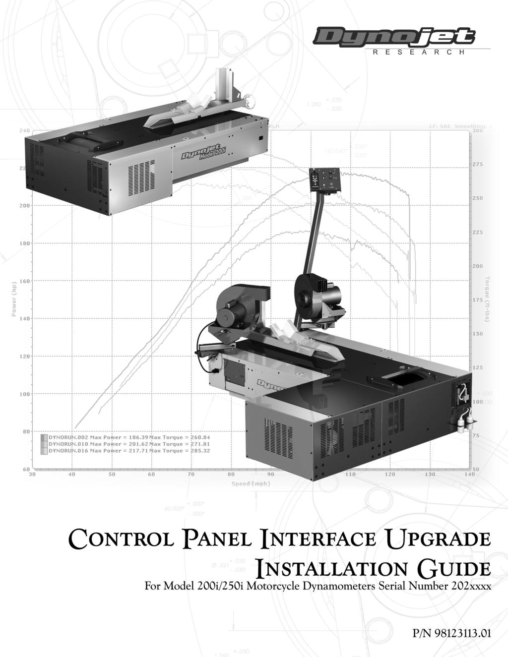
Control Panel Interface Upgrade Installation Guide For Model 200i and 250i Motorcycle Dynamometers Serial Number 202xxxx.
|
|
|
- Preston Edwards
- 5 years ago
- Views:
Transcription
1
2 2004 Dynojet Research, Inc. All Rights Reserved. Control Panel Interface Upgrade Installation Guide For Model 200i and 250i Motorcycle Dynamometers Serial Number 202xxxx. This manual is copyrighted by Dynojet Research, Inc., hereafter referred to as Dynojet, and all rights are reserved. This manual is furnished under license and may only be used or copied in accordance with the terms of such license. This manual is furnished for informational use only, is subject to change without notice, and should not be construed as a commitment by Dynojet. Dynojet assumes no responsibility or liability for any error or inaccuracies that may appear in this manual. Except as permitted by such license, no part of this manual may be reproduced, stored in a retrieval system, or transmitted, in any form or by any means, electronic, mechanical, recording, or otherwise, without the prior written permission of Dynojet. The Dynojet logo is a trademark of Dynojet Research, Inc. Any trademarks, trade names, service marks, or service names owned or registered by any other company and used in this guide are the property of their respective companies. Dynojet Research, Inc., 2191 Mendenhall Drive, North Las Vegas, Nevada 89031, USA. Printed in USA. Part Number: Version 1 (04/04)

3 April 12, 2004 Control Panel Interface upgrade for 200i/250i Dynos Serial Number 202xxxx These instructions are intended for use with installing the Control Panel Interface upgrade into Dynojet Research model 200i and 250i dynos with a serial number prefix of 202. Before proceeding, check the serial number on the dyno front left corner to verify it is in this range. The Dynojet part number for this upgrade is P/N If the serial number on your dyno does not start with 202 you will need a different kit for the upgrade. Contact Dynojet with any questions. This upgrade requires that your dyno has the optional monitor tray and upright arm to allow the mounting of the Control Panel. If your dyno does not already have this option you will need to order it. Contact Dynojet for the information. The part number and description for this option is P/N Monitor Tray and Upright Assembly. This upgrade requires the altering of wiring that carries 240 volts during normal dyno operation. Failure to follow these instructions could result in exposure to hazardous voltages or damage to your dyno. If you do not feel that you can follow these instructions properly and safely, contact Dynojet. Read all of these instructions before proceeding. 1. Unplug all power cords going into the dyno. This includes the main power cord and any additional cords. Remove the carriage and the top cover on the carriage module. Remove the covers over the retarder (if present) and the drum. Remove Retarder and Drum Cover Remove carriage and carriage module cover Note: Dynojet recommends using a hardened 5/32-inch hex driver (such as Snap-On FA5E) to remove the 1/4-inch screws. A standard allen key may round off in the shallow screw head. 1

4 2. Once the covers are off, inspect your dyno to verify that the starter brace is installed. If your dyno does not have a starter brace, contact Dynojet. The starter brace can be ordered under the P/N Starter Brace, M/C3. The starter brace supports the back of the starter and provides a good ground connection. Starter Brace 3. If a battery is installed, disconnect the negative terminal of the battery first then remove the positive terminal. If any battery charger has been installed, remove it. If you do not have a battery it will be necessary to purchase one. The high current draw for the Wheel Clamp and the Motorized Carriage is pulled from the car battery. The Control Panel Interface has a built in battery charger to recharge the battery after each use. Refer to your dyno install manual for the battery specifications. 4. Remove the side door covering the Power Distribution assembly. If the Breakout board has connections to the brake output pins on TB3, loosen the barrier strip connections and remove these two wires. Remove top 2 connections on this barrier strip 2

5 5. Disconnect the red battery cable from the starter and the black battery cable from the ground connection. If your dyno does not have a starter brace as shown, contact Dynojet. Disconnect the starter solenoid wire. All wires should be removed from the starter. Disconnect the red and black wires that go into the black box on the back wall of the drum module. Remove these wires Disconnect Yellow/Black twisted wire Remove Red and Black wires at other end 6. If the starter switch has been installed through one of the cable access holes, remove the cable access plate and feed the starter switch back into the dyno and coil up in the front inside of the dyno. This will not be used with the new hardware. 7. If your dyno has an air brake installed, trace the wires from the air brake solenoid to the black box. Cut the black solenoid wires at the point where the wires are extended to connect to the black box. If your dyno has an external switch attached to your dyno room door, disconnect it from the black box. 8. Remove the black box and the external starter switch. 3


6 9. Disconnect the white 4 pin connector from the DIN barrier strip rail on the back side of the Power Distribution assembly to the lower fuse panel assembly. Disconnect the Air Pump power connector on the front side of the Power Distribution assembly. DIN barrier strip Fuse sub panel Disconnect this connector 10. Remove the two screws that hold the fuse sub panel in place then remove the panel and set aside. Disconnect air pump power cable Remove screw Remove screw 4
7 11. Disconnect the blue and brown wires that connect from the DIN barrier strip on the back of the Power Distribution assembly from the 15A fan breakers. Pull only on the quick lug connectors on the back of the breakers and take care to not pull on the wires. Do not disturb any other connections. 15A breakers DIN barrier strip Disconnect these wires from the 15A breakers 5

8 12. Remove the power supply bracket by cutting the cable ties and removing the two 8-32 screws from the front side of the Power Distribution assembly and save for later use. Power Supply Bracket 13. Install the new power supply bracket, which has the power supply installed, with the two 8-32 screws from the front side of the Power Distribution assembly. 6


9 14. Slide the Control Panel Interface board assembly into the rear of the Power Distribution assembly as shown. Make sure to have the sheetmetal centered in the guides. Fasten the assembly in place with two 8-32 x 3/8-inch screws in the back and two in the front. 8-32x3/8-inch screws 8-32x3/8-inch screws 15. Install the P/N connector sticker to the front of the Power Distribution assembly. 7


10 16. Route the fan breaker and Control Panel Interface wires. You will need the wiring harness kit P/N Connect the 5.5-inch blue wire labeled H to the lower left lug of the 15A circuit breaker. 18. Connect the 8-inch blue wire labeled I to the lower left lug of the upper 15A circuit breaker. 19. Connect the 6-inch brown wire labeled J to the top left lug of the bottom 15A circuit breaker. 20. Connect the 9-inch brown wire labeled K to the top left lug of the upper 15A circuit breaker. I K J H Bottom 15A breaker 21. Connect P/N Control Panel Interface power supply cable to P9 on the Control Panel Interface board route behind the wires coming from the bottom of the DIN rail and between the top and middle circuit breaker connect to J1 and J2 on the power supply. Observe the locking tab on the white connector. It needs to lock into place with the locking tab on the power supply connector. The locking tab on the 3 pin connector at the top of the power supply should point down. The locking tab on the 6 pin connector should point up. Route through here P9 8

11 22. Connect the wires from the DIN power rail to the Control Panel Interface board. 23. Connect the brown wire from the bottom DIN terminal #1 to Tab 4 on the Control Panel Interface board. 24. Connect the blue wire from the bottom DIN terminal #4 to Tab 3 on the Control Panel Interface board. 25. Connect the brown wire from the bottom DIN terminal #2 to Tab 2 on the Control Panel Interface board. 26. Connect the blue wire from the bottom DIN terminal #5 to Tab 1 on the Control Panel Interface board. Add cable ties as shown in the picture. Cut the cable ties flush. #1 #5 Tab 4 Tab 3 Tab 2 Tab 1 9

12 27. Connect the brown wire from the top left connection of the lower 15A circuit breaker to Tab 8 on the Control Panel Interface board. 28. Connect the blue wire from the bottom left connection of the lower 15A circuit breaker to Tab 7 on the Control Panel Interface board. 29. Connect the brown wire from the top left connection of the upper 15A circuit breaker to Tab 6 on the Control Panel Interface board. 30. Connect the blue wire from the lower left connection of the upper 15A circuit breaker to Tab 5 on the Control Panel Interface board. Cable tie as shown. Cut the cable ties flush. Upper 15A Breaker Tab 8 Tab 7 Tab 6 Tab 5 10


13 31. Route the wiring to the optional Wheel Clamp and Power Carriage through the dyno. You may find it easier to slide the Stack Box out of the side of the dyno and remove its support bracket for routing these cables. Even if you have not purchased these optional accessories it is better to install the cables now for an easy upgrade in the future. Remove bracket 32. Remove the front cable access plate. Route the P/N Pod to Clamp cable from P5 on the Control Panel Interface board to the front cable hole on the dyno. The cable passes under the center partition in the carriage module and in front of the vertical angle piece that forms the structure of the front of the dyno. Make sure that the cable strain relief end with the conduit nut is at the end of the cable that will connect to the Wheel Clamp. P8 Power Carriage connection Control Panel Interface board P5 Wheel Clamp connection 11


14 33. Route the P/N Pod to Carriage cable from P8 on the Control Panel Interface board to the front cable hole on the dyno. The cable passes under the center partition in the carriage module and in front of the vertical angle. Make sure that the cable strain relief end with the conduit nut is at the end of the cable that will connect to the carriage. The strain relief for both the Power Carriage and the Wheel Clamp must end up outside of the dyno. Strain relief 34. If you already had the serial cable to the PC routed through the front panel put it in with one of the new cables and put the snap bushing around the cable. Install the cable pass through cover with the two holes as shown. 12


15 35. Re-install the Stack Box support bracket with four ¼-20 x ½ -inch hex head bolts. Re-install the Stack Box and secure with four ¼-20 x ½ -inch hex head bolts. Support Bracket 36. Connect the P/N Air Pump cable to P11 on the Control Panel Interface front side and route the cable out the rear hole on the Control Panel Interface to the back of the dyno. P11 Air Pump supply Air pump cable & AFR sensor cable Air pump cable & AFR sensor cable 13


16 37. If you have an air brake, install P/N cable into P7 in the Control Panel Interface board and run the short cable to the Breakout board as shown and connect. Cable tie as shown and route the other end to the air brake solenoid. Strip back the wires to the brake air solenoid and crimp into the barrel connections on the P/N Air Brake cable. If you do not have an air brake, then skip installing this cable Air Brake cable Connect here Strip back and crimp to barrel connectors 14


17 38. Route the wire harness to the Control Panel assembly. Depending on the location of the monitor upright, the wire harness can be routed to either side of the dyno. The P/N cable plugs in the Control Panel Interface board P4. This cable should be cable tied to the Power Distribution assembly to make sure the cable does not pull on the board. Cable tie here P4 39. If you do not have a monitor tray and stand it will be necessary to purchase one from Dynojet to mount the Control Panel assembly. The cable bundle to the Control Panel needs to be run out the cable access port by the monitor upright and a split bushing installed to protect the cable bundle. Change the cable access plate for the one included in the kit with two holes. Route the pendant cable through one split bushing and the cable to the Control Panel through the other. 15
18 40. Early production Monitor Arms, uprights, and the monitor tray may not have the tapped holes for routing the Control Panel cables and mounting the Control Panel. If your monitor stand arms do not have these holes, it will be necessary for you to drill and tap the holes in the monitor upright and the arms to allow for attaching the Control Panel cable bundle. The cable bundle needs to be arranged across the monitor arms to allow for easy movement of the monitor stand without pulling on the cables. The following diagram shows where to drill and tap the holes in the monitor upright. Drill and tap 8-32 holes in the arms about four inches in from each end. 16

19 41. The Control Panel needs to be disassembled so the cable to the Control Panel Interface can be connected. Remove the screw and nuts shown and lift off the back/side cover. Remove nuts Remove these screws Remove this cover 17


20 42. Connect the Control Panel cable to the Control Panel Button board. Cable tie the incoming cable as shown. Cable tie here 43. Replace the Control Panel cover with the hardware that you removed before. 18


21 44. Mount the Control Panel to the side of the monitor tray. The cable lengths are set to allow installing the Control Panel on either side of the monitor tray for easy access. Route the cable bundle along the arms with service loops to allow movement. Make sure that during normal arm movement the cable does not get pinched. 19


22 45. The battery cables and starter cables need to be connected next. The 4 pin connector plugs into the back side of the Control Panel Interface board near the middle of the board to P2. The cable routes out of the back of the Power Distribution assembly as shown. P2 Route here and cable tie Battery to Control Panel Interface cable 46. Install the starter support bracket, if necessary, and connect the other end of the battery cables to the starter as shown. 20


23 47. Route the cables to the cable support bracket as shown. Cable tie as shown. Make sure that all of the cables clear any moving components. Only connect the positive terminal on the battery at this time. If this is the first time you have installed a battery in this dyno refer to the dyno install guide for instructions on installing the battery hold down bracket. Cable Support Bracket 21


24 48. If you purchased either the Wheel Clamp or the Motorized Carriage, position the Motorized Carriage motor and/or the Wheel Clamp close to the dyno and plug in their motor cables for testing. 22


25 49. If you have an air brake and your dyno room is equipped with a safety switch on the door, it is necessary to connect the safety switch to the Control Panel Interface board interlock input to apply the air brake whenever the dyno room door is open. Connect the wires feeding the switch contacts to Interlock 1-A and Interlock 6-B connection points on the Control Panel Interface board. The board is shipped with a jumper wire in this location. Remove the jumper wire and replace with the wires to the door safety switch. This circuit must be closed for normal dyno runs. Connect safety switch wires here in place of jumper 50. Connect the negative terminal on the battery. Plug the dyno in to the 240VAC single phase outlet. - 23
26 51. Turn on the main breaker on side of the dyno by moving it to the up position. Make sure the E-Stop button on the Control Panel is in the out position. Twist if necessary to take it out of E-Stop. Turn on the switch on the front of the Stack box. 52. If you have the optional High Speed Blowers, verify they are plugged in to the sides of the dyno then press the fan control buttons on the Control Panel and verify that the fans turn on and off. Press once to turn on and once to turn off. 53. If you have the optional internal AFR pump installed, turn on the AFR pump and verify its operation. Press once to turn on and once to turn off. High Speed Blower Control AFR pump 24

27 54. If you purchased the optional Wheel Clamp then press the left hand clamp button and verify that the Wheel Clamp closes. Release the button. Press the right hand clamp button first then press the left hand clamp button and hold both buttons to open the clamp. Refer to the user s manual for more details of the operation. 55. If you purchased the optional Motorized Carriage then press the carriage forward and back buttons and verify carriage movement. Carriage Control Buttons Wheel Clamp Control Buttons 56. Turn off the dyno main breaker and unplug the dyno main power cord. Install the Control Panel Interface drip cover with three 8-32 x ¼ -inch screws. 25

28 57. Install the door stop chain with the two 8-32 nuts. 58. Put the carriage module cover back on. Put the drum and retarder module covers back on. Install the carriage. 59. Plug the dyno power cable in and turn on the main breaker on the power distribution assembly. Turn on the power switch on the front of the stack box. Start up the WinPEP software and verify that the program still communicates to the dyno hardware. 60. Press the starter switch and hold to verify starter operation. The speed indication in WinPEP should show drum speed. Release the starter switch when the drum is up to top speed. Press the red pendant button and verify that the dyno brakes or retarder do stop the dyno. 61. If you have the optional high speed blowers, turn then on and off to verify operation. 62. If you have the optional AFR integral pump, turn it on and off to verify its operation. 63. If you have the optional Motorized Carriage, run it back and forth to verify its operation. 64. If you have the optional Wheel Clamp either load a bike or put a bike wheel into the clamp and press the left hand clamp button and hold until the clamp stops and the indicator light between the clamp buttons is on steady. Press the right hand button first and hold then press the left hand button to release the clamp. Refer to the user s manual for more details on the operation. 65. If you have an air brake and a safety switch on the dyno room door then open the dyno room door and verify that the air brakes do apply. 26
29
Torque Module Installation and User Guide for model 250i Motorcycle Dynamometers.
 2000-2005 Dynojet Research, Inc. All Rights Reserved. Torque Module Installation and User Guide for model 250i Motorcycle Dynamometers. This manual is copyrighted by Dynojet Research, Inc., hereafter referred
Dynojet Research, Inc. All Rights Reserved. Air Fuel Ratio Module Installation and User Guide.
 2014-2015 Dynojet Research, Inc. All Rights Reserved.. This manual is copyrighted by Dynojet Research, Inc., hereafter referred to as Dynojet, and all rights are reserved. This manual, as well as the software
Air Fuel Ratio Module and AFR-4 Pump Assembly Installation and User Guide.
 2007-2012 Dynojet Research, Inc. All Rights Reserved.. This manual is copyrighted by Dynojet Research, Inc., hereafter referred to as Dynojet, and all rights are reserved. This manual, as well as the software
Torque Cell Installation Guide for Model 250i/250iP DynoWare RT Dynamometers.
 2015 Dynojet Research, Inc. All Rights Reserved. Torque Cell Installation Guide for Model 250i/250iP DynoWare RT Dynamometers. This manual is copyrighted by Dynojet Research, Inc., hereafter referred to
Dynojet Research, Inc. All Rights Reserved. Tire Temperature Sensor Installation Guide
 1998-2006 Dynojet Research, Inc. All Rights Reserved. This manual is copyrighted by Dynojet Research, Inc., hereafter referred to as Dynojet, and all rights are reserved. This manual, as well as the software
Power Carriage Installation Guide
 Power Carriage Installation Guide 1999-2002 Dynojet Research, Inc. All Rights Reserved. 020116SD Dynojet Research, Inc. 200 Arden Drive Belgrade, MT 59714 2191 Mendenhall Drive North Las Vegas, NV 89031
2006 Dynojet Research, Inc. All Rights Reserved. Spring Applied Air Release (SAAR) Brake Assembly Installation
 Brake Assembly Installation") 2006 Dynojet Research, Inc. All Rights Reserved. This manual is copyrighted by Dynojet Research, Inc., hereafter referred to as Dynojet, and all rights are reserved. This manual, as well as the software
2006 Dynojet Research, Inc. All Rights Reserved. This manual is copyrighted by Dynojet Research, Inc., hereafter referred to as Dynojet, and all rights are reserved. This manual, as well as the software
Dynojet Research, Inc. All Rights Reserved. Optical RPM Sensor Installation Guide.
 1993-2001 Dynojet Research, Inc. All Rights Reserved.. This manual is copyrighted by Dynojet Research, Inc., hereafter referred to as Dynojet, and all rights are reserved. This manual, as well as the software
INSTALLATION GUIDE. Dynojet Research 2191 Mendenhall Drive Suite 105, North Las Vegas NV,
 INSTALLATION GUIDE www.dynojetwb2.com Dynojet Research 2191 Mendenhall Drive Suite 105, North Las Vegas NV, 89081 1-800-992-4993 2008 Dynojet Research, Inc. All Rights Reserved. Wideband 2 Installation
Maintenance Guide For Model 224, Model 224 with 4WD, Model 424x, and Model 248 Automotive Dynamometers.
 2004-2008 Dynojet Research, Inc. All Rights Reserved. Maintenance Guide For Model 224, Model 224 with 4WD, Model 424x, and Model 248 Automotive Dynamometers. This manual is copyrighted by Dynojet Research,
Sea Doo 4-Tec Supercharged 1500cc Watercraft (Throttle By Wire models) Dynojet CMDM-6212
 Dynojet CMDM-6212") 2009-2012 Sea Doo 4-Tec Supercharged 1500cc Watercraft (Throttle By Wire models) Dynojet CMDM-6212 2012 Dynojet Research, Inc. All Rights Reserved. 2009-2012 Sea Doo 4-Tec Supercharged 1500cc Watercraft
2009-2012 Sea Doo 4-Tec Supercharged 1500cc Watercraft (Throttle By Wire models) Dynojet CMDM-6212 2012 Dynojet Research, Inc. All Rights Reserved. 2009-2012 Sea Doo 4-Tec Supercharged 1500cc Watercraft
750 Paso Wiring Upgrade
 750 Paso Wiring Upgrade Supplies required: 2 Bosch 30A/12V Relays # #0 332 209 150 (with mounting tab) 1 30 Amp fuse holder 1 10 Amp fuse holder 12 inches of brown 12 gauge wire 60 inches of red 14 gauge
Linx System with Atra Flex Installation for Model 424 Automotive Dynamometers
 2009-2018 Dynojet Research, Inc. All Rights Reserved. Linx System with Atra Flex Installation for Model 424 Automotive Dynamometers This manual is copyrighted by Dynojet Research, Inc., hereafter referred
Motorcycle Dynamometer Installation Guide
 Motorcycle Dynamometer Installation Guide 1993-2002 Dynojet Research, Inc. All Rights Reserved. 020329SD Dynojet Research, Inc. 200 Arden Drive Belgrade, MT 59714 2191 Mendenhall Drive North Las Vegas,
Eddy Current Brake Installation and User Guide For Model 224 Above Ground Automotive Dynamometers.
 2004-2008 Dynojet Research, Inc. All Rights Reserved. Eddy Current Brake Installation and User Guide For Model 224 Above Ground Automotive Dynamometers. This manual is copyrighted by Dynojet Research,
Eddy Current Brake Installation and User Guide For In Ground Model 224 Automotive Dynamometers.
 2004-2008 Dynojet Research, Inc. All Rights Reserved. Eddy Current Brake Installation and User Guide For In Ground Model 224 Automotive Dynamometers. This manual is copyrighted by Dynojet Research, Inc.,
Inverting Fault Circuit Breaker Kit for FlexPak 3000 and WebPak 3000 Digital DC Drives VAC and VAC
 Inverting Fault Circuit Breaker Kit for FlexPak 3000 and WebPak 3000 Digital DC Drives 40-75 HP @ 230 VAC and 75-150 HP @ 460 VAC Model Numbers: 906FK1101 and 906FK1201 Instruction Manual D2-3330-2! ATTENTION:
Spreader and Vehicle Battery Kits
 May 5, 20 Lit. No. 922, Rev. 04 and Vehicle Battery Kits Hopper s Parts List and Installation Instructions CAUTION Read this document before installing the and Vehicle Battery Kit. CAUTION Use standard
Dynojet Research, Inc. All Rights Reserved. Installation Guide For the Kart and ATV Dynamometers.
 1993-2005 Dynojet Research, Inc. All Rights Reserved. Installation Guide For the Kart and ATV Dynamometers. This manual is copyrighted by Dynojet Research, Inc., hereafter referred to as Dynojet, and all
Eddy Current Brake Installation and User Guide For Model 224 Pit Automotive Dynamometers.
 2004-2005 Dynojet Research, Inc. All Rights Reserved. Eddy Current Brake Installation and User Guide For Model 224 Pit Automotive Dynamometers. This manual is copyrighted by Dynojet Research, Inc., hereafter
PLEASE READ ALL DIRECTIONS BEFORE STARTING INSTALLATION
 PARTS LIST FUEL AND IGNITION 2008-2017 Royal Enfield All EFI Models Installation Instructions 1 Power Commander 1 USB Cable 1 Installation Guide 2 Power Commander Decals 2 Dynojet Decals 1 Alcohol swab
PLEASE READ ALL DIRECTIONS BEFORE STARTING INSTALLATION
 PARTS LIST 2009-2011 Moto Guzzi Stelvio Installation Instructions 1 Power Commander 1 USB Cable 1 Installation Guide 2 Power Commander Decals 2 Dynojet Decals 1 O2 Optimizer 3 Velcro strips 1 Alcohol swab
Harley-Davidson and the Bar & Shield logo are among the trademarks of H-D Michigan, LLC.
 2010-2012 Dynojet Research, Inc. All Rights Reserved. Harley-Davidson JUMPSTART Intallation and User Guide This manual is copyrighted by Dynojet Research, Inc., hereafter referred to as Dynojet, and all
PLEASE READ ALL DIRECTIONS BEFORE STARTING INSTALLATION
 PARTS LIST 2013-2014 Honda CB500 / CBR500R Installation Instructions 1 Power Commander 1 USB Cable 1 Installation Guide 2 Power Commander Decals 2 Dynojet Decals 2 Velcro strips 1 Alcohol swab 1 Posi-tap
ZONE BLOCKAGE AND FLOW MONITOR INSTALLATION MANUAL
 ZONE BLOCKAGE AND FLOW MONITOR INSTALLATION MANUAL Document revision: 1.1 Last revised: February 24, 2017 Zone Blockage and Flow Monitor Installation Manual 2017 Intelligent Agricultural Solutions. All
Installation Guide For Model 248 Four Post Lift Automotive Dynamometers.
 1993-2005 Dynojet Research, Inc. All Rights Reserved. Installation Guide For Model 248 Four Post Lift Automotive Dynamometers. This manual is copyrighted by Dynojet Research, Inc., hereafter referred to
Vibrator Kit. Stainless Steel & Poly Hopper Spreaders with FLEET FLEX Electrical System
 October 1, 2016 Lit. No. 95098, Rev. 01 PARTS LIST Vibrator Kit Stainless Steel & Poly Hopper Spreaders with FLEET FLEX Electrical System 5 7 6 9 8 4 1 10 2 3 99504 1 Vibrator Kit Item Part Qty Description
PLEASE READ ALL DIRECTIONS BEFORE STARTING INSTALLATION
 PARTS LIST 2006-2007 Yamaha R6 Installation Instructions 1 Power Commander 1 USB Cable 1 Installation Guide 2 Power Commander Decals 2 Dynojet Decals 2 Velcro strips 1 Alcohol swab 1 Posi-tap THE IGNITION
SELF DRILL SCREWS FILLER STRIP
 r ve Pickup Lift Mounting Instructions Fullsize Ford Trucks- F-150 2015-present Preparing the Gate 1. Remove the mounting hardware which is banded to the liftgate. 2. Verify mounting bracket kit (Figure
PLEASE READ ALL DIRECTIONS BEFORE STARTING INSTALLATION
 PARTS LIST 2010-2012 MV Agusta Brutale 1090 Installation Instructions 1 Power Commander 1 USB Cable 1 Installation Guide 2 Power Commander Decals 2 Dynojet Decals 2 Velcro strips 1 Dual Lock strip 1 Alcohol
EasyStart Installation Instructions for Dometic Family RV A/Cs
 EasyStart Installation Instructions for Dometic Family RV A/Cs DuoTherm Brisk Brisk II Penguin Penguin II Contents Introduction... 4 Safety first... 4 Making a good crimp... 4 Identifying Dometic AC Units...
Installation Instructions. PowerFlex 700 Drive - Frame 8 Components Replacement
 Installation Instructions PowerFlex 700 Drive - Frame 8 Components Replacement Important User Information Solid-state equipment has operational characteristics differing from those of electromechanical
PLEASE READ ALL DIRECTIONS BEFORE STARTING INSTALLATION
 FUEL AND IGNITION 2011-2013 Suzuki Kingquad 400 Installation Instructions PARTS LIST 1 Power Commander 1 USB Cable 1 CD-ROM 1 Installation Guide 2 Power Commander Decals 2 Dynojet Decals 2 Velcro Strips
2016 POWERSPORTS DYNAMOMETER PRICELIST
 2016 POWERSPORTS DYNAMOMETER PRICELIST DYNAMOMETER AND DIAGNOSTIC TEST EQUIPMENT FEATURED DYNAMOMETER OF: Dynojet Research, Inc. 2191 Mendenhall Drive North Las Vegas, NV 89081 Tel (800) 992-3525 Int Tel
PLEASE READ ALL DIRECTIONS BEFORE STARTING INSTALLATION
 PARTS LIST 2015 Yamaha FJ-09 Installation Instructions 1 Power Commander 1 USB Cable 1 Installation Guide 2 Power Commander Decals 2 Dynojet Decals 3 Velcro strips 1 Alcohol swab 1 Posi-tap 1 O2 Optimizer
UNPACK AND IDENTIFY THE FOLLOWING PARTS.
 SUT-250-M2 ASSEMBLY REQUIREMENTS *Torque all T-bolt nuts to 35-40 foot pounds. *Check all lights before towing. *Tire pressure not to exceed recommendation on serial tag. *Re-torque wheel nuts after first
PLEASE READ ALL DIRECTIONS BEFORE STARTING INSTALLATION
 PARTS LIST 2014 Honda VFR 800 Installation Instructions 1 Power Commander 1 USB Cable 1 Installation Guide 2 Power Commander Decals 2 Dynojet Decals 2 Velcro strips 1 Alcohol swab 1 O2 Optimizer THE IGNITION
Spreader and Vehicle Battery Kits
 March 1, 2013 Lit. No. 94879, Rev. 11 and Vehicle Battery Kits Hopper s Parts Lists and Installation Instructions Read this document before installing the and Vehicle Battery Kit. Use standard methods
and Original Series Pickup Lift Mounting Instructions Fleetside Chevy & GMC Trucks Fleetside 4-door Chevy & GMC Trucks T-100
 r ve and Original Series Pickup Lift Mounting Instructions Fleetside Chevy & GMC Trucks - 1960-1987 Fleetside 4-door Chevy & GMC Trucks - 1988-1991 Preparing the Gate 1. Remove the mounting hardware which
PLEASE READ ALL DIRECTIONS BEFORE STARTING INSTALLATION
 PARTS LIST 2010-2011 Aprilia RSV4 Installation Instructions 1 Power Commander 1 USB Cable 1 Installation Guide 2 Power Commander Decals 2 Dynojet Decals 2 Velcro strips 1 Alcohol swab 2 Posi-taps 1 Secondary
INSTALL INSTRUCTIONS DC C-EV. Installation Instructions: DC C-EV.
 INSTALL INSTRUCTIONS DC6-48-60-0-8C-EV Installation Instructions: DC6-48-60-0-8C-EV INSTALL INSTRUCTIONS DC6-48-60-0-8C-EV Contents Section Description Page 1 Copyright 2 1.1 Disclaimer 2 1.2 Warnings
ACCESSORY KIT INSTALLATION INSTRUCTIONS
 ACCESSORY KIT INSTALLATION INSTRUCTIONS GAS HEAT KIT FOR -60 F OPERATION KIT MODELS 2BC04700106, 2BC04700151 and 2BC04700154 FOR SINGLE PACKAGE AIR CONDITIONERS 6.5 THRU 12.5 TONS MODELS DM, DL, J**DM,
MODEL SCA Installation and Operation Manual Important:
 MODEL SCA Installation and Operation Manual Important: This manual contains specific cautionary statements relative to worker safety. Read this manual thoroughly and follow as directed. It is impossible
PLEASE READ ALL DIRECTIONS BEFORE STARTING INSTALLATION
 PARTS LIST 2006-2011 Yamaha MT-03 Installation Instructions 1 Power Commander 1 USB Cable 1 Installation Guide 2 Power Commander Decals 2 Dynojet Decals 2 Velcro strips 1 Alcohol swab 1 O2 Optimizer THE
Installation Guide for Above Ground Model 224 Automotive Dynamometers.
 2005-2014 Dynojet Research, Inc. All Rights Reserved. Installation Guide for Above Ground Model 224 Automotive Dynamometers. This manual is copyrighted by Dynojet Research, Inc., hereafter referred to
and Original Series Pickup Lift Mounting Instructions T-150-T T-150 PART#5177 T-150-T
 Fullsize Chevy & GMC Trucks- 988-999 Toyota Tundra- 2000-2006 Toyota T-00-993-999 Preparing the Gate r ve and Original Series Pickup Lift Mounting Instructions. Remove the mounting hardware which is banded
and Original Series Pickup Lift Mounting Instructions Fullsize Nissan Titan Trucks present T-420 BOLT-ON GUSSET PART#5257
 and Original Series Pickup Lift Mounting Instructions Fullsize Nissan Titan Trucks- 2004-present Preparing the Gate 1. Remove the mounting hardware which is banded to the liftgate. 2. Verify mounting bracket
PLEASE READ ALL DIRECTIONS BEFORE STARTING INSTALLATION
 PARTS LIST 2010 MV Agusta Brutale 1090 Installation Instructions 1 Power Commander 1 USB Cable 1 CD-ROM 1 Installation Guide 2 Power Commander Decals 2 Dynojet Decals 2 Velcro 1 Dual Velcro 1 Alcohol swab
PLEASE READ ALL DIRECTIONS BEFORE STARTING INSTALLATION
 PARTS LIST 2011-2013 KTM 690R Enduro Installation Instructions 1 Power Commander 1 USB Cable 1 Installation Guide 2 Power Commander Decals 2 Dynojet Decals 2 Velcro strips 1 Alcohol swab 3 Zip ties 1 O2
PLEASE READ ALL DIRECTIONS BEFORE STARTING INSTALLATION
 PARTS LIST 2010-2012 Ducati Hypermotard 1100 EVO Installation Instructions 1 Power Commander 1 USB Cable 1 Installation Guide 2 Power Commander Decals 2 Dynojet Decals 2 Velcro strips 1 Alcohol swab 4
Spreader and Vehicle Battery Kits
 March 1, 2013 Lit. No. 94644, Rev. 03 and Vehicle Kits Hopper s Parts Lists and Installation Instructions Read this document before installing the and Vehicle Kit. Use standard methods and practices when
INSTALLATION MANUAL. Document revision: 1.3 Last revised: January 2, 2019
 INSTALLATION MANUAL Document revision: 1.3 Last revised: January 2, 2019 Recon SpreadSense Installation Manual 2017-19 Intelligent Agricultural Solutions. All Rights Reserved. Recon SpreadSense Installation
ELECTRICAL SYSTEM UPGRADE
 NEW CONTROLLER & ELECTRICAL SYSTEM UPGRADE FOR DAIRY TECH, INCORPORATED 10, 30 & 60G PASTEURIZERS Parts to Include 2 Wire ties (Nuts) 2 sticky wire mount pads Large Rubber Grommet (for bottom of electric
PLEASE READ ALL DIRECTIONS BEFORE STARTING INSTALLATION
 PARTS LIST FUEL AND IGNITION 2017-2018 Husqvarna 701SM Installation Instructions 1 Power Commander 1 USB Cable 1 Installation Guide 2 Power Commander Decals 2 Dynojet Decals 2 Velcro strips 1 Alcohol swab
PLEASE READ ALL DIRECTIONS BEFORE STARTING INSTALLATION
 PARTS LIST 2013 Honda CB1100 Installation Instructions 1 Power Commander 1 USB Cable 1 CD-ROM 1 Installation Guide 2 Power Commander Decals 2 Dynojet Decals 2 Velcro 1 Alcohol swab 1 O2 Optimizer THE IGNITION
PLEASE READ ALL DIRECTIONS BEFORE STARTING INSTALLATION
 PARTS LIST 2006-2014 Suzuki M109R / C109R Installation Instructions 1 Power Commander 1 USB Cable 1 Installation Guide 2 Power Commander Decals 2 Dynojet Decals 2 Velcro strips 1 Alcohol swab 1 Zip tie
AUXILIARY BATTERY BOX INSTALLATION INSTRUCTIONS
 AUXILIARY BATTERY BOX INSTALLATION INSTRUCTIONS The original TOMMY GATE hydraulic lift Assembling the Auxiliary Battery Box 1. Remove the cover from the auxiliary battery box by removing the two nuts and
Installation Guide for In Ground Model 224 Automotive Dynamometers.
 2014-2015 Dynojet Research, Inc. All Rights Reserved. Installation Guide for In Ground Model 224 Automotive Dynamometers. This manual is copyrighted by Dynojet Research, Inc., hereafter referred to as
Wiring the 2015 FRC Control System
 Wiring the 2015 FRC Control System This document details the wiring of a basic electronics board for bench-top testing. The images shown in this section reflect the setup for a Robot Control System using
PLEASE READ ALL DIRECTIONS BEFORE STARTING INSTALLATION
 PARTS LIST 2014 Honda CB650F / CBR650F Installation Instructions 1 Power Commander 1 USB Cable 1 Installation Guide 2 Power Commander Decals 2 Dynojet Decals 2 Velcro strips 1 Alcohol swab 1 O2 Optimizer
Revision A
 Remanufactured 82-90XL Pinspotter Safety Guard Kit Installation Manual 400-082-001 Revision A 82-90XL Pinspotter Safety Guard Kit Installation Manual, 400-082-001, Rev. A Summary of Changes Change No.
G-170. r ve Pickup Lift Mounting Instructions Fullsize Chevy & GMC Trucks- 1500, 2500 & 3500: 2007-present
 Fullsize Chevy & GMC Trucks- 1500, 2500 & 3500: 2007-present Preparing the Gate 1. Remove the mounting hardware which is banded to the liftgate. 2. Verify mounting bracket kit (Figure 1 and Table 1). 18-5/8"
HARLEY DAVIDSON SOFTAIL MODELS INSTALLATION INSTRUCTIONS
 2001-2006 HARLEY DAVIDSON SOFTAIL MODELS INSTALLATION INSTRUCTIONS PARTS LIST quantity description 1 power commander EX 1 USB cable 1 cd-rom 1 installation guide 1 power adapter 2 power commander EX decal
PLEASE READ ALL DIRECTIONS BEFORE STARTING INSTALLATION
 PARTS LIST 2009-2011 Yamaha R1 Installation Instructions 1 Power Commander 1 USB Cable 1 Installation Guide 2 Power Commander Decals 2 Dynojet Decals 2 Velcro strips 1 Dual Lock strip 1 Alcohol swab 1
INSTALLATION INSTRUCTIONS FOR THE TOMAHAWK ELECTRIC REVERSE
 INSTALLATION INSTRUCTIONS FOR THE TOMAHAWK ELECTRIC REVERSE LAST UPDATED: April 2018 Thank you for choosing the Motor Trike Electric Reverse. We ask that you read the directions before you start and follow
Installation Instructions Electric Heaters 5 20 kw
 Small Packaged Products 2 to 5 Tons Accessory Electric Heaters Cancels: IIK 564A-24-2 IIK 564A-24- -02 Installation Instructions Electric Heaters 5 20 kw NOTE: Read the entire instruction manual before
PLEASE READ ALL DIRECTIONS BEFORE STARTING INSTALLATION
 PARTS LIST 2009 MV Agusta Brutale 1078 Installation Instructions 1 Power Commander 1 USB Cable 1 Installation Guide 2 Power Commander Decals 2 Dynojet Decals 2 Velcro strips 1 Alcohol swab 1 O2 Optimizer
PLEASE READ ALL DIRECTIONS BEFORE STARTING INSTALLATION
 PARTS LIST 2012-2015 BMW G650 GS Installation Instructions 1 Power Commander 1 USB Cable 1 Installation Guide 2 Power Commander Decals 2 Dynojet Decals 2 Velcro strips 1 Alcohol swab 2 Posi-taps THE IGNITION
SUT-250-S (These instructions are used for SUT-250-SCLC also)
") SUT-250-S (These instructions are used for SUT-250-SCLC also) Torque wrench, carpenters square, wire cutters, Phillips screwdriver, 7/16, 9/16, and 3/4 combination wrenches, ratchet, 9/16, 3/4, 13/16,
SUT-250-S (These instructions are used for SUT-250-SCLC also) Torque wrench, carpenters square, wire cutters, Phillips screwdriver, 7/16, 9/16, and 3/4 combination wrenches, ratchet, 9/16, 3/4, 13/16,
GL1800 TRAILER HITCH - INSTALLATION INSTRUCTIONS #GL
 GL1800 TRAILER HITCH - INSTALLATION INSTRUCTIONS #GL18007-20 Read through these instructions completely before attempting installation, lay out all pieces including the numbered hardware bags to familiarize
PLEASE READ ALL DIRECTIONS BEFORE STARTING INSTALLATION
 PARTS LIST 2015 Ducati Scrambler Installation Instructions 1 Power Commander 1 USB Cable 1 Installation Guide 2 Power Commander Decals 2 Dynojet Decals 2 Velcro strips 1 Alcohol swab 1 Posi-tap THE IGNITION
Installation Instructions Electric Heaters 5 20 kw
 Small Packaged Products to 5 Tons Accessory Electric Heaters Cancels: IIK 564A--1 IIK 564A-- 11-01 Installation Instructions Electric Heaters 5 0 kw NOTE: Read the entire instruction manual before starting
PLEASE READ ALL DIRECTIONS BEFORE STARTING INSTALLATION
 PARTS LIST 2015-2017 Ducati Scrambler Installation Instructions 1 Power Commander 1 USB Cable 1 Installation Guide 2 Power Commander Decals 2 Dynojet Decals 2 Velcro strips 1 Alcohol swab 1 Posi-tap THE
PLEASE READ ALL DIRECTIONS BEFORE STARTING INSTALLATION
 PARTS LIST FUEL AND IGNITION 2012-2014 KTM 690R Duke Installation Instructions 1 Power Commander 1 USB Cable 1 Installation Guide 2 Power Commander Decals 2 Dynojet Decals 2 Velcro strips 1 Alcohol swab
PLEASE READ ALL DIRECTIONS BEFORE STARTING INSTALLATION
 PARTS LIST FUEL AND IGNITION 2014-2015 Yamaha Bolt 950 Installation Instructions 1 Power Commander 1 USB Cable 1 Installation Guide 2 Power Commander Decals 2 Dynojet Decals 2 Velcro strips 1 Alcohol swab
PLEASE READ ALL DIRECTIONS BEFORE STARTING INSTALLATION
 PARTS LIST 2008-2009 Yamaha R6 Installation Instructions 1 Power Commander 1 USB Cable 1 CD-ROM 1 Installation Guide 2 Power Commander Decals 2 Dynojet Decals 2 Velcro 1 Alcohol swab 1 Posi-tap 1 O2 optimizer
Allen-Bradley HP Inverting Fault Circuit Breaker Kit
 Allen-Bradley 1397 400-600HP Inverting Fault Circuit Breaker Kit Cat. Nos. 1397-IFB600 What This Option Provides This option is intended to be applied to regenerative 1397 drives with high inertia loads.
Honda CBR600RR
 Parts List 2007-2012 Honda CBR600RR Installation Instructions 1 Power Commander 1 USB Cable 1 CD-ROM 1 Installation Guide 2 Power Commander Decals 2 Dynojet Decals 2 Velcro Strip 1 Alcohol Swab The ignition
Feeder Circuit Breaker Units Secure Support Pan and Change Door Latch
 Installation Instructions Feeder Circuit Breaker Units Secure Support Pan and Change Door Latch Catalog Numbers 2193FZ Topic Page About This Publication 1 Required Tools 1 Important User Information 2
XLR-8 60 Extended Rack Autosampler
 XLR-8 60 Extended Rack Autosampler Quick Installation Guide Manual Part Number 480226 Rev 0 COPYRIGHT 2015 Teledyne Technologies Incorporated. All rights reserved. 480226 Rev 0, October, 2015 Printed in
Control Box Wiring For PRSstandard Tool
 888-680-4466 ShopBotTools.com Control Box Wiring For PRSstandard Tool Copyright 2017 ShopBot Tools, Inc. page 1 Copyright 2017 ShopBot Tools, Inc. page 2 Table of Contents Introduction...5 Installation...5
COLD WEATHER START KIT Platinum Mini Split
 COLD WEATHER START KIT Platinum Mini Split Cold Weather Start Kit: To be used in conjunction with Platinum Mini Split cooling system. The Coolest Thing In Wine Storage LASS.MPS 051515 Conforms to ANSI/UL
APOLLO Model # - F-12013, F-22013, D-50115, D-50215, D-50415, D-50615, D-50815, D Apollo Series- Instruction Manual V.3
 Apollo Series- Instruction Manual V.3 APOLLO Model # - F-12013, F-22013, D-50115, D-50215, D-50415, D-50615, D-50815, D-51015 This instruction manual serves as a guide for the Apollo Series. IMPORTANT!
PLEASE READ ALL DIRECTIONS BEFORE STARTING INSTALLATION
 PARTS LIST FUEL AND IGNITION 2008-2011 Kawasaki Brute Force 750 Installation Instructions 1 Power Commander 1 USB Cable 1 CD-ROM 1 Installation Guide 2 Power Commander Decals 2 Dynojet Decals 2 Velcro
PLEASE READ ALL DIRECTIONS BEFORE STARTING INSTALLATION
 PARTS LIST 2008-2010 KTM RC8 2009-2010 KTM RC8R I n s t a l l a t i o n I n s t r u c t i o n s 1 Power Commander 1 USB Cable 1 CD-ROM 1 Installation Guide 2 Power Commander Decals 2 Dynojet Decals 2 Velcro
Mirror Solutions Bevel & Pivot Models Installation Instructions INSTALLATION INSTRUCTIONS. Figure 1
 Installation Instructions Mirror Solutions Bevel & Pivot Models 620095-620098 Mirror Solutions Bevel - Models # 620095 & 620096 Mirror Solutions Pivot - Models # 620097 & 620098 Figure 1 INSTALLATION INSTRUCTIONS
SADDLEBAG AUDIO WIRE HARNESS KIT P/N
 SADDLEBAG AUDIO WIRE HARNESS KIT P/N 2880986 APPLICATION ALL INDIAN MOTORCYCLES WITH BOTH TRUNK AND SADDLEBAG AUDIO INSTALLED BEFORE YOU BEGIN Read these instructions and check to be sure all parts and
Wiring the 2016 FRC Control System
 Wiring the 2016 FRC Control System This document details the wiring of a basic electronics board for bench-top testing. The images shown in this section reflect the setup for a Robot Control System using
PLEASE READ ALL DIRECTIONS BEFORE STARTING INSTALLATION
 PARTS LIST 2010 Harley Davidson Sportster 1200 I n s t a l l a t i o n I n s t r u c t i o n s 1 Power Commander 1 USB Cable 1 CD-ROM 1 Installation Guide 2 Power Commander Decals 2 Dynojet Decals 2 Velcro
RECON ZONE BLOCKAGE AND FLOW MONITOR INSTALLATION MANUAL. Document revision: 1.2 Last revised: October 25, 2017
 RECON ZONE BLOCKAGE AND FLOW MONITOR INSTALLATION MANUAL Document revision: 1.2 Last revised: October 25, 2017 Recon Zone Blockage and Flow Monitor Installation Manual 2017 Intelligent Agricultural Solutions.
PLEASE READ ALL DIRECTIONS BEFORE STARTING INSTALLATION
 PARTS LIST FUEL AND IGNITION 2017 Kawasaki Z125 Installation Instructions 1 Power Commander 1 USB Cable 1 Installation Guide 2 Power Commander Decals 2 Dynojet Decals 2 Velcro strips 1 Alcohol swab 1 Posi-tap
PLEASE READ ALL DIRECTIONS BEFORE STARTING INSTALLATION
 PARTS LIST FUEL AND IGNITION 2012-2014 Harley Davidson Softail Installation Instructions 1 Power Commander 1 USB Cable 1 Installation Guide 2 Power Commander Decals 2 Dynojet Decals 2 Velcro strips 1 Alcohol
PLEASE READ ALL DIRECTIONS BEFORE STARTING INSTALLATION
 PARTS LIST 2008-2010 Polaris RZR 800 / S Installation Instructions 1 Power Commander 1 USB Cable 1 Installation Guide 2 Power Commander Decals 2 Dynojet Decals 2 Velcro strips 1 Alcohol swab 2 Zip ties
Safe-T-element Installation Instructions
 Safe-T-element Installation Instructions For: PTI STEZA (2x2 Burner Configuration) & PTI STEZB (3x1 Burner Configuration) Revision K (May. 3 2012) TABLE OF CONTENTS 1. PREPARATION... 3 1.1 General Safety
Blade and Off Truck Kit
 Fisher Engineering 50 Gordon Drive, Rockland, Maine 0484 www.fisherplows.com 5080 000 October 5, 08 Lit. No. 458, Rev. 08 Blade and Off Truck Kit XLS Snowplow Parts List A DIVISION OF FISHER, LLC XLS
PLEASE READ ALL DIRECTIONS BEFORE STARTING INSTALLATION
 PARTS LIST 2006-2014 Yamaha Roadliner/Stratoliner Installation Instructions 1 Power Commander 1 USB Cable 1 Installation Guide 2 Power Commander Decals 2 Dynojet Decals 1 O2 Optimizer 2 Velcro strips 1
PLEASE READ ALL DIRECTIONS BEFORE STARTING INSTALLATION
 PARTS LIST FUEL AND IGNITION 2015 Kawasaki VN1700 Models Installation Instructions 1 Power Commander 1 USB Cable 1 Installation Guide 2 Power Commander Decals 2 Dynojet Decals 2 Velcro strips 1 Alcohol
Installation Manual for the Pantera Ignition Switch Bypass
 Installation Manual for the Pantera Ignition Switch Bypass This Ignition Switch Bypass solves the Pantera owners problem of replacing the ignition switch that is expensive and difficult to source. The
Please read ALL directions before starting installation
 Parts List 2009 Victory Vision I n s t a l l a t i o n I n s t r u c t i o n s 1 Power Commander 1 USB Cable 1 CD-ROM 1 Installation Guide 2 Power Commander Decals 2 Dynojet Decals 2 Velcro 1 Alcohol swab
SPACESAVER EC-300 A ELECTRICS
 INSTALLATION INSTRUCTIONS SPACESAVER EC-300 A ELECTRICS SECTION I TOP MOUNTED ELECTRICS SECTION II FACE PANEL MOUNTED ELECTRICS SECTION III ZFS INSTALLATION INSTRUCTIONS This symbol indicates a connection