Trail Rocker Installation Instructions
|
|
|
- Shon Flowers
- 5 years ago
- Views:
Transcription


1 Trail Rocker Installation Instructions Manual #90580 For Installing Painless Part Numbers: and Painless Performance Products recommends you, the installer, read this installation manual from front to back before installing this harness. 1
2 Perfect Performance Products, LLC Painless Performance Products Division 2501 Ludelle St. Fort Worth, TX PHONE: FAX: If you have any questions concerning the installation of this harness, feel free to call Painless Performance Products' Tech Line at The Tech Line can be reached from 8 A.M. to 5 P.M. central time, Monday through Thursday, and 8 A.M. to 4:30 P.M. on Fridays. We have attempted to provide you with as accurate of instructions as possible and are always concerned about corrections or improvements that can be made. If you have found any issues or omissions, or simply have comments or suggestions concerning these instructions, please write us at the above address, send us a fax at (817) , or us at painless@painlessperformance.com. We sincerely appreciate your business. Perfect Performance Products, LLC shall in no event be liable in contract or tort (including negligence) for special, indirect, incidental, or consequential damages, such as but not limited to, loss of property damage, or any other damages, costs or expenses which might be claimed as the result of the use or failure of the goods sold hereby, except only the cost of repair or replacement. 2
 423-9696.")
3 CONTENTS Refer to the Contents Figure (below) to take inventory. See that you have everything you re intended to have in this kit. If you find that anything is missing or damaged, please contact the dealer where you obtained the kit or Painless Performance at (800) The Painless Trail Rocker Kits and should contain the following: Relay Center pre-installed to powder coated bracket. 200 Amp midi fuse Switch Panel with 5 pre-installed switches Ignition power splice and weather-pack connector. Parts Kits: (12) un-insulated butt connectors, (12) pre-cut head shrink, (3) Adel Connectors, (3) ¼ 20 Stainless Bolts, (3) ¼ nylon locking nuts, (2) ¼ stainless nuts, (2) lock washers, (2) flat washers, (1) rubber grommet This manual (90580) SMALL PARTS Included with the Painless harness are parts kits containing miscellaneous terminals, fuses, screws, and nuts. Many of the terminals are non-insulated and will require heat shrink to be applied after the terminal has been properly crimped. Heat shrink has been supplied. 3


4 These non-insulated terminals allow you to keep a cleaner, more traditional look; colored insulated terminals would seem out of place. When crimping these terminals, take notice to the split in the terminal. Make sure the smooth side of the jaw on the crimper goes towards this split. TOOLS NEEDED In addition to your regular hand tools, you will need, at least, the following tools: Stripping Tools: A good set of wire strippers are required to strip wire properly. This style of wire stripper is ideal for this harness install because of its ability to properly strip wire gauges 10 to 20.These are available from just about any local auto parts store, electrical supply shop, home improvement store or can be purchased online. Volt/Ohm Meter: A Volt/Ohm meter is always a good tool to have on hand when installing any type of electrical components into any vehicle. Most basic units provide the two functions required to diagnose electrical issues seen during a harness install. These two functions are the ability to read DC Voltage and electrical continuity or Ohms. They can be purchased from any home improvement store, local hardware store and electrical supply shop and online. Heat Gun: Very useful to shrink the heat-shrink found in the parts kit. Basic Hand Tools For tightening the relay center bracket, etc. 4


5 INSTALLATION Beginning on the Page 7 is a picture by picture, step by step installation guide for installing your new Trail Rocker. These steps MUST be followed as they are printed. Do not move onto other parts of the installation out of sequence. 5

6 BEFORE BEGINNING INSTALLATION Before removing the negative terminal on the battery, you will need to: Set Parking Brake Turn key to RUN position Place shift lever into D position Pull 4 wheel drive lever into 4L position CAUTION: BEFORE THE INSTALLATION OF THIS PRODUCT, DISCONNECT THE POWER FROM YOUR VEHICLE BY REMOVING THE NEGATIVE BATTERY CABLE FROM THE BATTERY. THE BATTERY SHOULD NOT TO BE RECONNECTED UNTIL INSTRUCTED 6


7 Step 1: Using a 10mm socket, loosen and remove the negative battery cable from the battery. 7


8 Step 2: Using wire cutters, cut loose the two Umbrella Style Zip Ties on top of the battery tray. 8
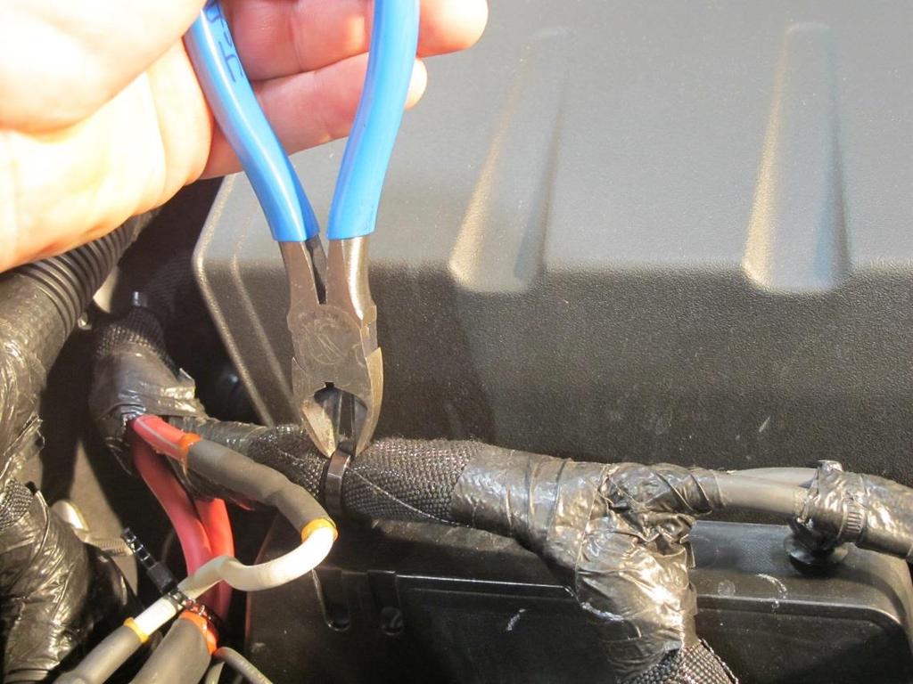
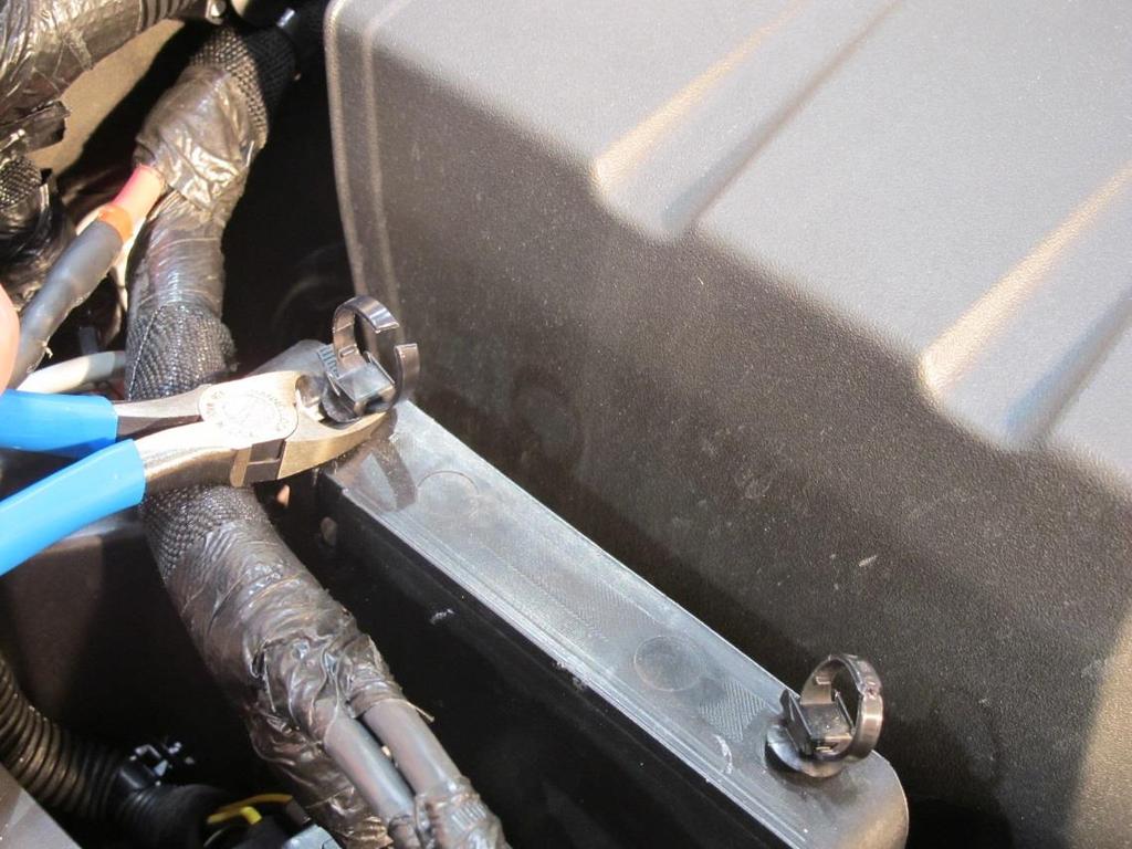
9 9


10 Step 3: Position Adel clamp over the factory wiring harness. Step 4: Mount Adel clamp to inside wall of factory battery tray using supplied ¼ 20 Bolt, flat washer, and ¼ nylon locking nut. 10


11 Step 5: Using 10mm wrench or socket, remove factory battery tray mounting nut from the stud on the firewall. (For ease of installation, we recommend removing factory engine cover) 11


12 Step 6: Position Trail Rocker relay center mounting bracket over the factory firewall mounted stud. 12

13 Step 7: Position Adel clamps over the Trail Rocker wiring harness. 13
 flat washers, and (2) nylon")

14 Step 8: Using provided (2) ¼ 20 bolts, (2) flat washers, and (2) nylon locking nuts, mount the Relay Center bracket to the factory battery tray as shown. 14


15 Step 9: Using a 10mm wrench or socket, reinstall factory battery tray nut to stud on firewall. 15


16 Step 10: Route Trail Rocker control wires across the firewall. Secure the control wires to the factory harness loom using provided zip ties. You can now reinstall your engine cover. Step 11: On the driver side of the engine bay, locate the horn and remove it using a 10mm wrench or socket. 16

17 Step 12: With the horn removed, you can now access the pass-through on the firewall. This is your access point to route the control wires into the interior. (Note: You may need to push open the factory carpet using your finger) 17


18 Step 13: Carefully route the white control wire connector through the pass-through. Step 14: Apply provided rubber grommet over control wires with the slit facing up. 18


19 Step 15: Push/apply grommet into firewall access hole as shown. 19


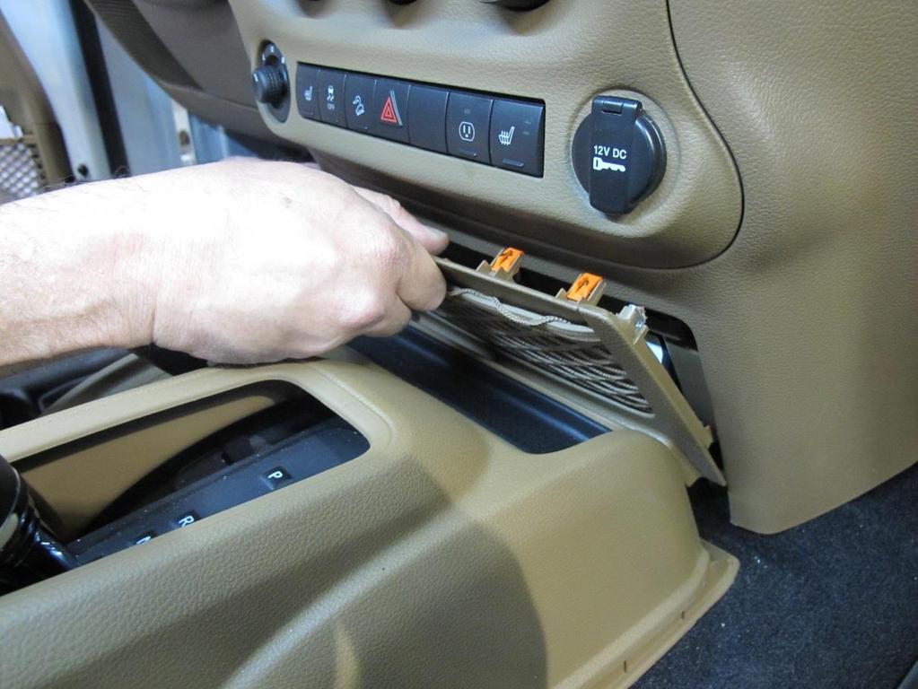
20 Step 16: We will now move to the interior of the vehicle. In order to install the switch panel, you will need to reposition the center console. To do this, you need to pull up on it. (There are no screws or bolts, only retainer clips.) 20


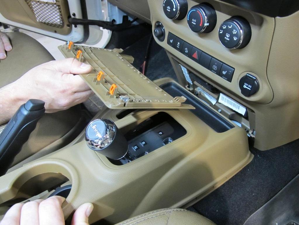
21 Step 17: With the center console positioned back, you will now remove the netted storage panel from the dash by using a pry tool, or carefully pulling on the netting. 21
22 22


23 Step 18: With the old panel removed, you will now install the Trail Rocker switch panel. First you will need to route the control wire plug as shown below. 23


24 Step 19: With the control wires routed and pulled through, you will now position and clip in the new Trail Rocker switch panel. Press down firmly to ensure the panel locks in place at the bottom. 24
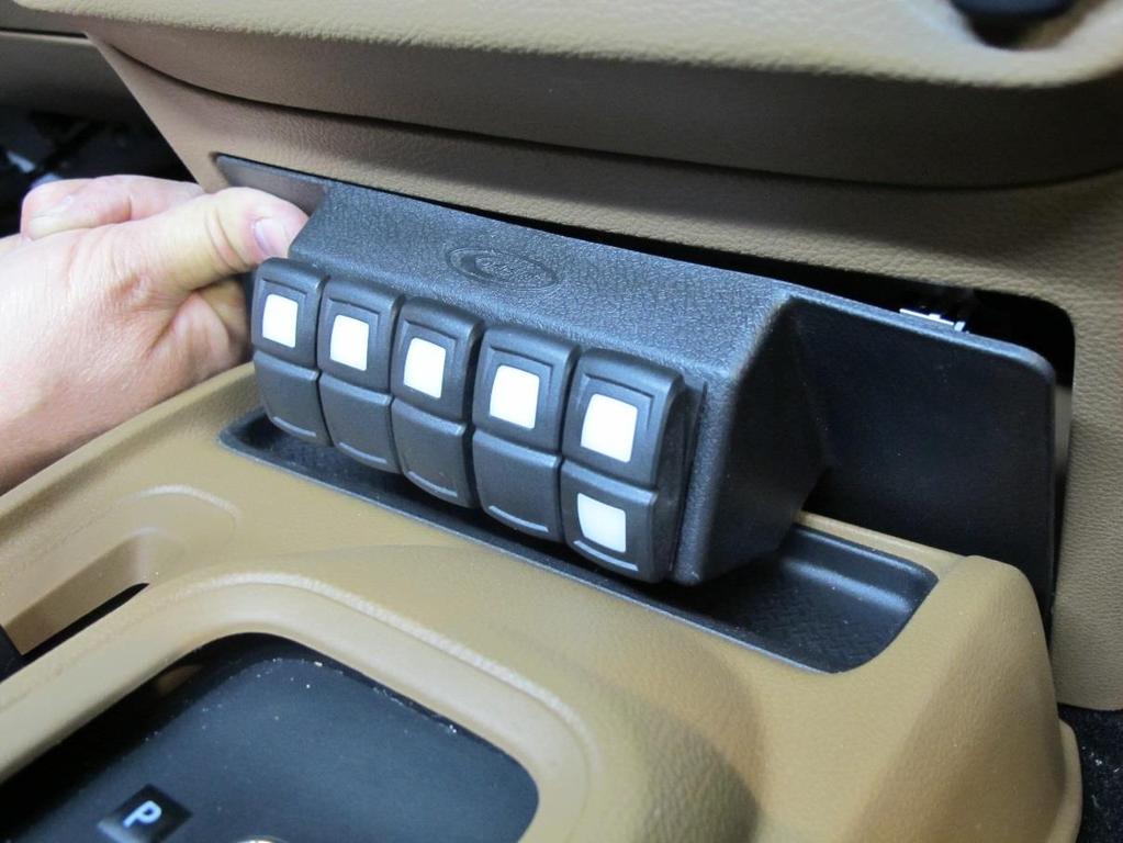
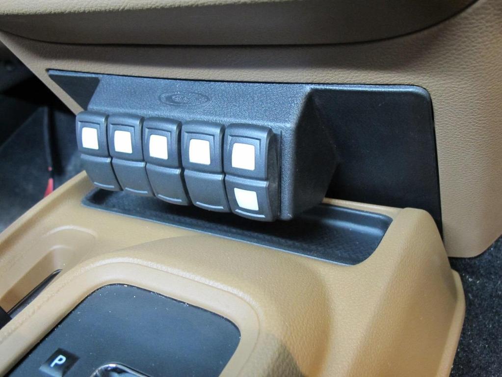
25 25

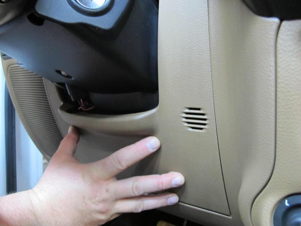
26 IF YOU WANT TO OPERATE YOUR SWITCHES WITH A CONSTANT POWER (AS SHIPPED), YOU WILL SKIP STEPS THESE STEPS ILLUSTRATE HOW TO HOOK UP YOUR TRAIL ROCKER TO IGNITION SWITCHED POWER. Step 20: You will now remove the panel below the steering column by carefully pulling from the top first. 26


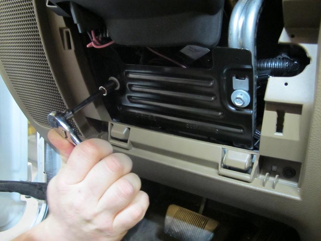
27 Step 21: With the plastic panel out of place, you will now use a 10mm socket or wrench to remove the two bolts holding the metal bracket in place. 27


28 Step 22: You will now locate the ignition switch connector and remove it. Using a small flathead screwdriver, unlock the orange locking clip. 28


29 Step 23: With the locking clip unlocked, you will squeeze the bottom of the connector and remove it by pulling it down. Step 24: You will now peel back the convoluted tubing covering the wires running to the ignition switch connector and cut the Pink/White Ignition 12V wire about 2 inches from the connector. 29


30 Step 25: Now it is time to unpin your factory ignition switched 12V wire. To do this, you will first use a small screwdriver or pick to remove the blue locking mechanism. 30


31 Step 26: With the blue lock removed, you will now use a small pick or screwdriver to depress the lock underneath the middle terminal. (Pin 3 = Ignition Switched 12V) 31


32 Step 27: With the terminal unlocked, you will now pull the terminal out of the connector. 32

33 Provided in your parts kit is a replacement Pink/White wire that will provide your Trail Rocker with ignition switched power while allowing you to terminate into the factory ignition switched 12V wire. 33
 with the supplied ignition")

34 Step 28: You will now re-pin the factory ignition switch connector (Pin #3) with the supplied ignition switch wire. Step 29: With the ignition switch wire fastened, you will now reinstall the blue locking mechanism. 34

35 Step 30: You will now strip the factory pink/white 22 gauge wire 3/8 an inch. Once stripped, you will fold the copper wire in half, ensuring a tight connection into the butt connector. Once stripped, you will now crimp the factory wire into the open end of the butt connector on the provided Trail Rocker ignition wire. (NOTE: make sure the heat shrink is installed before crimping). 35


36 Step 31: After crimping, you will now slide the heat shrink over the connection. Using a heat source, heat the heat shrink ensuring a tight wrap around the connector. Step 32: Reinstall the factory convoluted tubing over the Trail Rocker ignition switched 12V wire and factory wires. 36


37 Step 33: Reinstall the factory ignition switch connector. Step 34: You will now connect the weather pack connector from the ignition switched 12V to the white control wire plug. 37


38 Step 35: Connect the white control wire plug to the switch panel plug. Once connected, apply zip ties to factory wiring. 38


39 Step 36: Reinstall metal bracket and plastic panel. 39
40 40
41 Step 37: OUTPUT WIRE ROUTING. As there are many accessories available that the Trail Rocker can control, there are no specific pictures of output wire installation. You will route these wires to the location of your components. Ensure to route safely, avoiding high heat areas, moving parts, and sharp edges. It is suggested to use grommets for any wires passing through metal to avoid wearing through the wire insulation and causing arcing. Make sure any accessories and components you install are properly grounded. 41

42 Output Wire Color Diagram: Switch #1: Grey/White Switch #2: Blue Switch #3: Yellow/White Switch #4: Orange Switch #5: Blue/Yellow Switch #6: Purple Extra output wires: Output #7: Pink Output #8: Green 42
 dual blade connector terminals, shown below.")
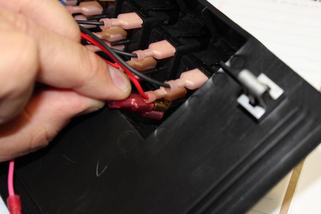
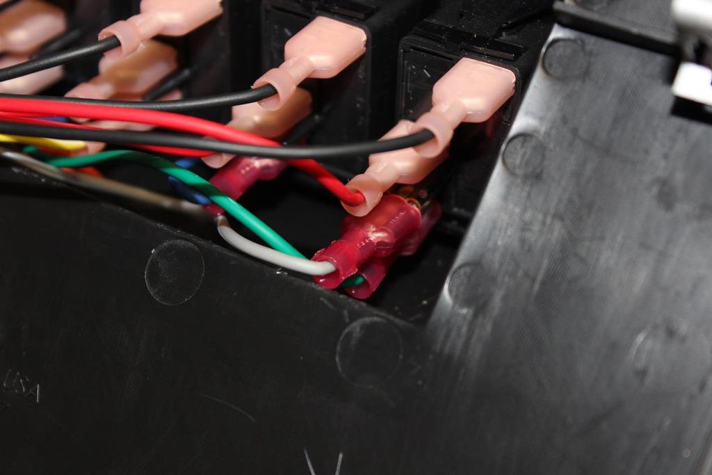
43 OPTIONAL: If you are wanting to use the two extra Output Wires (#7 Pink and #8 Green), they will need to be wired into the existing switches. Pages will provide a step-by-step tutorial on achieving this. Provided in the kit are (2) dual blade connector terminals, shown below. 43


44 Once you choose the switch you want to have control the extra output, you will disconnect the female terminal of the existing wire (from the male terminal on the bottom of the switch) and double up with the extra Output Wire using one of the provided dual blade connector 44


45 After pressing the extra Output Wire onto the dual blade terminal, you will press on the female terminal of the original wire you removed from the switch. Once both wires are installed onto the dual blade connector, you will then slide it onto the terminal on the switch you initially removed the control wire from. 45
46 46


47 Step 38: After wiring in your components to the output wiring, you may now reconnect the negative terminal of your battery. 47


48 Step 39: With the battery connected, you can now test out and enjoy your new Trail Rocker! 48
49 NOTES 49
50 50
51 Painless Performance Limited Warranty and Return Policy Chassis harnesses, fuel injection harnesses, Trail Rocker and Striker ColdShot units are covered under a lifetime warranty. All other products manufactured and/or sold by Painless Performance are warranted to the original purchaser to be free from defects in material and workmanship under normal use. Painless Performance will repair or replace defective products without charge during the first 12 months from the purchase date. No products will be considered for warranty without a copy of the purchase receipt showing the sellers name, address and date of purchase. You must return the product to the dealer you purchased it from to initiate warranty procedures. 51
52 Painless Performance Products LLC 2501 Ludelle Street Fort Worth, TX Phone (817)
Trail Rocker Installation Instructions
 Trail Rocker Installation Instructions Manual #90581 For Installing Painless Part Numbers: 57002 Painless Performance Products recommends you, the installer, read this installation manual from front to
Trail Rocker Installation
 Trail Rocker Installation Instructions Customizable Trail Rocker Control System For Installing Painless Part Number: 57100 Manual #90616 Painless Performance Products recommends you, the installer, read
Trail Rocker Installation Instructions
 Trail Rocker Installation Instructions Trail Rocker - Genesis Bracket For Installing Painless Part Number: 57200 Manual # 90591 To be used with Painless Kit # s: 57000-57005 Painless Performance Products
Trail Rocker Installation
 Trail Rocker Installation Instructions 4, 6, or 8 - Switch Customizable Trail Rocker Switch Panel w/ Flanged Mount For Installing Painless Part Number: 57103, 57106, & 57109 Manual #90636 Painless Performance
Track Rocker Installation Instructions
 Track Rocker Installation Instructions Customizable Track Rocker Control System For Installing Painless Part Number: 58100 Track Rocker Relay Center Manual #90641 Painless Performance Products recommends
Track Rocker Installation Instructions
 Track Rocker Installation Instructions For Installing Painless Part Numbers: 58103: 8-Switch Customizable Track Rocker Switch Panel w/ Flanged Mount 58106: 6-Switch Customizable Track Rocker Switch Panel
Off-Road Switch Panel Installation Instructions
 Off-Road Switch Panel Installation Instructions 50330: Off-road 4 Toggle switches/dash Mount w/keyed Ignition Switch 50332: Off-road 6 Toggle switches/dash Mount w/keyed Ignition Switch Painless Performance
Wire Harness Installation Instructions
 Wire Harness Installation Instructions For Installing: Part #50001 Race Car Kit/8 Circuit Part #50201 8 Switch Dash Mounted Panel Part #50202 8 Switch Roll Bar Mounted Panel Manual #90502 Painless Performance
Installation Instructions. Part #65100
 Installation Instructions Part #65100 Perfect Performance Products, LLC Painless Performance Products Division 2501 Ludelle Street Fort Worth, TX 76105-1036 800-423-9696 phone 817-244-4024 fax Web Site:
Installation Instructions
 Installation Instructions Part #40120 Perfect Performance Products, LLC Painless Performance Products Division 2501 Ludelle Street Fort Worth, TX 76105-1036 800-423-9696 phone 817-244-4024 fax Web Site:
PIN BULKHEAD CONNECTOR KIT
 2501 Ludelle Street Fort Worth, Texas 76105 817-244-6212 Phone 817-244-4024 Fax 888-350-6588 Sales 800-423-9696 Tech E-mail: painless@painlessperformance.com Web: www.painlessperformance.com 40130 22 PIN
Installation Instructions For 50330, 50331, 50332, and Off Road Switch Panels
 Installation Instructions For 50330, 50331, 50332, and 50333 Off Road Switch Panels 2501 Ludelle Street Fort Worth, Texas 76105 817-244-6212 Phone 817-244-4024 Fax 888-350-6588 Sales 800-423-9696 Tech
PERFECT HI-VELOCITY 62MM THROTTLE BODY
 PERFECT HI-VELOCITY 62MM THROTTLE BODY Installation Instructions Part # 65300 1991-1998 Jeep 4.0L Engines OR All Jeep 4.0L Engines in Cherokee, Grand Cherokee and Wrangler 1991-2005 w/4 wire IAC ONLY.
Part # GM LS2, 3 & 7-95mm Throttle Body
 Part # 65303 2006-2011 GM LS2, 3 & 7-95mm Throttle Body Perfect Performance Products, LLC 2501 Ludelle St. Fort Worth, Texas 76105 (800) 423-9696 1 We are always concerned about any corrections or improvements
Perfect Performance Products, LLC Painless Performance Products Division 2501 Ludelle St. Fort Worth, Texas (800)
") PERFECT HI-VELOCITY 68MM THROTTLE BODY Installation Instructions Part # 65301 1991-1998 Jeep 4.0L Engines w/perfect Engine Management System P/N 65140, 65141 OR All Jeep 4.0L Engines in Cherokee, Grand
PERFECT HI-VELOCITY 68MM THROTTLE BODY Installation Instructions Part # 65301 1991-1998 Jeep 4.0L Engines w/perfect Engine Management System P/N 65140, 65141 OR All Jeep 4.0L Engines in Cherokee, Grand
Installation Instructions For 50340
 Installation Instructions For 50340 2501 Ludelle Street Fort Worth, Texas 76105 817-244-6212 Phone 817-244-4024 Fax 888-350-6588 Sales 800-423-9696 Tech E-mail: painless@painlessperformance.com Web: www.painlessperformance.com
Perfect Performance Products, LLC Painless Performance Products Division 2501 Ludelle St. Fort Worth, Texas (800)
") PERFECT HI-VELOCITY 62MM THROTTLE BODY Installation Instructions Part # 65302 2005-2006 Jeep 4.0L All Jeep 4.0L Engines in Cherokee, Grand Cherokee, Wrangler and Rubicon. Perfect Performance Products,
PERFECT HI-VELOCITY 62MM THROTTLE BODY Installation Instructions Part # 65302 2005-2006 Jeep 4.0L All Jeep 4.0L Engines in Cherokee, Grand Cherokee, Wrangler and Rubicon. Perfect Performance Products,
Installation Instructions For #64160 Striker II Power Module GMC/Chevrolet Duramax LB7 Diesel Copyright
 Installation Instructions For #64160 Striker II Power Module 2001-2004 GMC/Chevrolet Duramax LB7 Diesel 2 nd Edition August 2007 Copyright 2006 by Perfect Performance Products, LLC 2501 Ludelle Street
Installation Instructions. Manual # For Installing: Part # Painless Gauge Controller
 Installation Instructions Manual #90579 For Installing: Part #60650- Painless Gauge Controller Perfect Performance Products, LLC Painless Performance Products Division 2501 Ludelle Street Fort Worth, TX
Installation Instructions For #64260 Striker FE Module GMC/Chevrolet Duramax LB7 Diesel Copyright
 Installation Instructions For #64260 Striker FE Module 2001-2004 GMC/Chevrolet Duramax LB7 Diesel 2 nd Edition August 2007 Copyright 2006 by Perfect Performance Products, LLC 2501 Ludelle Street Fort Worth,
200-4R TRANSMISSION LOCK-UP HARNESS INSTALLATION INSTRUCTIONS
 2501 Ludelle Street Fort Worth, Texas 76105 817-244-6212 Phone 817-244-4024 Fax 888-350-6588 Sales 800-423-9696 Tech E-mail: painless@painlessperformance.com Web: www.painlessperformance.com 60110 200-4R
Magnetic Door Jamb Switches (Ground Style) Installation Instructions
 Installation Instructions") 2501 Ludelle Street Fort Worth, Texas 76105 817-244-6212 Phone 817-244-4024 Fax 888-350-6588 Sales 800-423-9696 Tech E-mail: painless@painlessperformance.com Web: www.painlessperformance.com 80180 Magnetic
2501 Ludelle Street Fort Worth, Texas 76105 817-244-6212 Phone 817-244-4024 Fax 888-350-6588 Sales 800-423-9696 Tech E-mail: painless@painlessperformance.com Web: www.painlessperformance.com 80180 Magnetic
Installation Instructions For #64066 Striker I Power Module Ford Powerstroke 6.0L Diesel Copyright
 Installation Instructions For #64066 Striker I Power Module 2003-2006 Ford Powerstroke 6.0L Diesel 2 nd Edition August 2007 Copyright 2006 by Perfect Performance Products, LLC 2501 Ludelle Street Fort
Installation Instructions For #64060 Striker I Power Module GMC/Chevrolet Duramax LB7 Diesel
 2501 Ludelle Street Fort Worth, Texas 76105 817-244-6212 Phone 817-244-4024 Fax 888-350-6588 Sales 800-423-9696 Tech E-mail: painless@painlessperformance.com Web: www.painlessperformance.com Installation
Installation Instructions
 Installation Instructions Jeep JK Unlimited (2007 Present) Mounting Bracket and Air Line System Kit for ARB On-Board Twin Air Compressor (CKMTA12) Made in the USA Kit Contents: 1 Bracket for ARB Compressor
30107 & PACK & 6-PACK RELAY BANK
 30107 & 30108 2501 Ludelle Street Fort Worth, Texas 76105 817-244-6212 Phone 817-244-4024 Fax 888-350-6588 Sales 800-423-9696 Tech E-mail: painless@painlessperformance.com Web: www.painlessperformance.com
Installation Instructions
 Installation Instructions Jeep JK 2-Door (2011 Present) Mounting Bracket and Air Line System Kit for ARB On-Board Twin Air Compressor (CKMTA12) Made in the USA Kit Contents: 1 Flat Bracket 1 Formed Bracket
Installation Instructions For #64320 Striker Turbo Timer Module
 2501 Ludelle Street Fort Worth, Texas 76105 817-244-6212 Phone 817-244-4024 Fax 888-350-6588 Sales 800-423-9696 Tech E-mail: painless@painlessperformance.com Web: www.painlessperformance.com Installation
3-5 Hours Professional installation recommended
 I N S T A L L A T I O N G U I D E APPLICATION AMP Part # Chevrolet Silverado 2500/3500 / GMC Sierra 2500/3500 - Ext. Cab * 2007-201 75126-01A Chevrolet Silverado 2500/3500 / GMC Sierra 2500/3500 - Crew
3-5 Hours Professional installation recommended
 I N S T A L L A T I O N G U I D E APPLICATION MODEL YR PART # Toyota Tacoma Double Cab 2005 - up 75142-01A Toyota Tacoma Access Cab* 2005 - up 75142-01A * Modification required to running board assembly.
3-5 Hours Professional installation recommended
 I N S T A L L A T I O N G U I D E APPLICATION MODEL YR PART # Toyota Tacoma Double Cab 2016 75162-01A Toyota Tacoma Access Cab* 2016 75162-01A * Modification required to running board assembly. See Item
Ford Mustang V6 OEM-Style Fog Light Kit Parts List: Quantity: Tool List:
 2015-2017 Ford Mustang V6 OEM-Style Fog Light Kit Parts List: Quantity: Tool List: LED Foglights/ Bezels 2 Flat head & Phillips screwdriver (if you ordered part#3600) Ratchet & Socket set OR Wiring harness
Installation Instructions for Chevrolet Colorado, GMC Canyon, LT, Z71, With Factory Fog Lights
 Installation Instructions for 2015-2018 Chevrolet Colorado, GMC Canyon, LT, Z71, With Factory Fog Lights This kit is designed to allow use of your factory fog light operation along with an addition auxiliary
= Experienced
 I N S T A L L A T I O N G U I D E APPLICATION LENGTH MODEL YR PART # Ford F-250 / F-350 / F-450 Regular Cab * (48 ) 2002-2003, 2008-2016 75134-01A Ford F-250 / F-350 / F-450 Super Cab * (60 ) 2002-2003,
2-3 Hours Professional installation recommended
 I N S T A L L A T I O N G U I D E APPLICATION MODEL YR PART # Chevy Suburban / GMC Yukon XL / Escalade ESV 2015 76127-01A Escalade EXT 2015 76127-01A *Modification required to running board assembly. See
Model A Turn Signal Kit Installation Guide
 Model A Turn Signal Kit Installation Guide Creative Connections, Inc. Consumer Hot Line: 888-471-LOGO 770-476-7322 In Atlanta, GA http://www.logolites.com P/N: 100-005/K 2008 Creative Connections, Inc.
I N S T A L L A T I O N G U I D E. Chevrolet Silverado / GMC Sierra - Ext Cab * A (Diesel Only)
") I N S T A L L A T I O N G U I D E APPLICATION AMP Part # Chevrolet Silverado / GMC Sierra - Crew Cab 2011-201 751-01A (Diesel Only) Chevrolet Silverado / GMC Sierra - Ext Cab 2011-201* 751-01A (Diesel
I N S T A L L A T I O N G U I D E APPLICATION AMP Part # Chevrolet Silverado / GMC Sierra - Crew Cab 2011-201 751-01A (Diesel Only) Chevrolet Silverado / GMC Sierra - Ext Cab 2011-201* 751-01A (Diesel
3-5 Hours Professional installation recommended
 I N S T A L L A T I O N G U I D E APPLICATION AMP Part # Chevrolet Silverado500 / GMC Sierra 500 - Double Cab * 04-7 7554-0A Chevrolet Silverado500 / GMC Sierra 500- Crew Cab 04-7 7554-0A Chevrolet Silverado
AMP RESEARCH TECH SUPPORT (Press 2) Monday - Friday, 6:00 AM - 5:00 PM PST
 Monday - Friday, 6:00 AM - 5:00 PM PST") APPLICATION AMP Part # Jeep Wrangler Unlimited (JK) 2007 2017 78122-01A (-Door Only) INSTALLATION TIME 3-5 Hours Professional installation recommended SKILL LEVEL 1 2 3 = Experienced TOOLS REQUIRED q 13
APPLICATION AMP Part # Jeep Wrangler Unlimited (JK) 2007 2017 78122-01A (-Door Only) INSTALLATION TIME 3-5 Hours Professional installation recommended SKILL LEVEL 1 2 3 = Experienced TOOLS REQUIRED q 13
30140 &30142 F5 Dual Fan Controller
 2501 Ludelle Street Fort Worth, Texas 76105 817-244-6212 Phone 817-244-4024 Fax 888-350-6588 Sales 800-423-9696 Tech E-mail: painless@painlessperformance.com Web: www.painlessperformance.com 30140 &30142
I N S T A L L A T I O N G U I D E
 I N S T A L L A T I O N G U I D E APPLICATION AMP Part # Jeep Wrangler Unlimited (JK) 2007 2017 78122-01A (4-Door Only) INSTALLATION TIME 3-5 Hours Professional installation recommended SKILL LEVEL 1 2
Jeep Wrangler (TJ)
") INSTALLATION GUIDE APPLICATION MODEL YR PART # Bestop PART # Jeep Wrangler (TJ) 2003 2006 10-03315-10 751-01 INSTALLATION TIME 3:00 hrs SKILL LEVEL 1 2 3 4 4= Experienced TOOLS REQUIRED Safety goggles
INSTALLATION GUIDE APPLICATION MODEL YR PART # Bestop PART # Jeep Wrangler (TJ) 2003 2006 10-03315-10 751-01 INSTALLATION TIME 3:00 hrs SKILL LEVEL 1 2 3 4 4= Experienced TOOLS REQUIRED Safety goggles
I N S T A L L A T I O N G U I D E. AMP RESEARCH TECH SUPPORT (Press 2) Monday - Friday, 6:00 AM - 5:00 PM PST
 Monday - Friday, 6:00 AM - 5:00 PM PST") I N S T A L L A T I O N G U I D E APPLICATION AMP Part # Jeep Wrangler Unlimited (JK) 2007 2014 75121-01A 2-Door INSTALLATION TIME 3-5 Hours Professional installation recommended SKILL LEVEL 1 2 3 4 4=
I N S T A L L A T I O N G U I D E APPLICATION AMP Part # Jeep Wrangler Unlimited (JK) 2007 2014 75121-01A 2-Door INSTALLATION TIME 3-5 Hours Professional installation recommended SKILL LEVEL 1 2 3 4 4=
I N S T A L L A T I O N G U I D E. AMP RESEARCH TECH SUPPORT (Press 2) Monday - Friday, 6:00 AM - 5:00 PM PST
 Monday - Friday, 6:00 AM - 5:00 PM PST") I N S T A L L A T I O N G U I D E APPLICATION AMP Part # Jeep Wrangler Unlimited (JK) 2007 2017 78121-01A 2-Door INSTALLATION TIME 3-5 Hours Professional installation recommended SKILL LEVEL 1 2 3 4 4=
I N S T A L L A T I O N G U I D E APPLICATION AMP Part # Jeep Wrangler Unlimited (JK) 2007 2017 78121-01A 2-Door INSTALLATION TIME 3-5 Hours Professional installation recommended SKILL LEVEL 1 2 3 4 4=
INSTALLATION GUIDE. AMP RESEARCH TECH SUPPORT (Press 2) Monday - Friday, 6:00 AM - 5:00 PM PST
 Monday - Friday, 6:00 AM - 5:00 PM PST") INSTALLATION GUIDE APPLICATION AMP Part # Jeep Wrangler Unlimited (JK) 2007 2015 75122-01A (-Door Only) INSTALLATION TIME 3-5 Hours Professional installation recommended SKILL LEVEL 1 2 3 = Experienced
INSTALLATION GUIDE APPLICATION AMP Part # Jeep Wrangler Unlimited (JK) 2007 2015 75122-01A (-Door Only) INSTALLATION TIME 3-5 Hours Professional installation recommended SKILL LEVEL 1 2 3 = Experienced
2-3 Hours Professional installation recommended
 INSTALLATION GUIDE APPLICATION MODEL YR PART # Chevy Tahoe / GMC Yukon/ Cadillac Escalade * 2015-2017 76127-01A-B Chevy Suburban / GMC Yukon XL / Escalade ESV 2015-2017 76127-01A-B Escalade EXT 2015-2017
Hummer H up A Hummer H3T up A
 INSTALLATION GUIDE APPLICATION MODEL YR PART # Hummer H3 2006 - up 5116-01A Hummer H3T 2009 - up 5116-01A INSTALLATION TIME 3:00 hrs SKILL LEVEL 1 2 3 = Experienced TOOLS REQUIRED Safety goggles Measuring
30140 F5 Dual Fan Controller
 30140 F5 Dual Fan Controller 1 2501 Ludelle Street Fort Worth, Texas 76105 817-244-6212 Phone 817-244-4024 Fax 888-350-6588 Sales 800-423-9696 Tech E-mail: painless@painlessperformance.com Web: www.painlessperformance.com
Ford F150 SuperCab Ford F150 SuperCrew
 INSTALLATION GUIDE APPLICATION LENGTH MODEL YR PART # Ford F150 SuperCab 7 00-007 10-0996-11 Ford F150 SuperCrew 79 00-007 10-0996-1 INSTALLATION TIME 3:00 hrs SKILL LEVEL 1 3 = Experienced TOOLS REQUIRED
Ford F-150 Supercrew A (2004 Heritage) Ford F-150 Super Cab A
 Ford F-150 Super Cab A") INSTALLATION GUIDE APPLICATION LENGTH MODEL YR PART # Ford F-150 Supercrew 79 1999-2004 75111-01A (2004 Heritage) Ford F-150 Super Cab 72 1999-2003 75111-01A INSTALLATION TIME 3:00 hrs SKILL LEVEL 1 2
INSTALLATION GUIDE APPLICATION LENGTH MODEL YR PART # Ford F-150 Supercrew 79 1999-2004 75111-01A (2004 Heritage) Ford F-150 Super Cab 72 1999-2003 75111-01A INSTALLATION TIME 3:00 hrs SKILL LEVEL 1 2
2-3 Hours Professional installation recommended
 INSTALLATION GUIDE APPLICATION AMP Part # Chevrolet Silverado1500 / GMC Sierra 1500 - Double Cab * 2014-18 78154-01A Chevrolet Silverado1500 / GMC Sierra 1500- Crew Cab 2014-18 78154-01A Chevrolet Silverado
INSTALLATION GUIDE. AMP RESEARCH TECH SUPPORT (Press 2) Monday - Friday, 6:00 AM - 5:00 PM PST
 Monday - Friday, 6:00 AM - 5:00 PM PST") INSTALLATION GUIDE APPLICATION AMP Part # Chevrolet Silverado / GMC Sierra - Ext. Cab 2007 - up 75123-01A Chevrolet Silverado / GMC Sierra - Crew Cab 2007 - up 75126-01A Chevrolet Silverado / GMC Sierra
INSTALLATION GUIDE APPLICATION AMP Part # Chevrolet Silverado / GMC Sierra - Ext. Cab 2007 - up 75123-01A Chevrolet Silverado / GMC Sierra - Crew Cab 2007 - up 75126-01A Chevrolet Silverado / GMC Sierra
I N S T A L L A T I O N G U I D E. Ford Transit - Single Sided A (All slider and barn door models)
") I N S T A L L A T I O N G U I D E APPLICATION MODEL YR PART # Ford Transit - Single Sided 2014-2017 76159-01A (All slider and barn door models) INSTALLATION TIME 3-5 Hours Professional installation recommended
I N S T A L L A T I O N G U I D E APPLICATION MODEL YR PART # Ford Transit - Single Sided 2014-2017 76159-01A (All slider and barn door models) INSTALLATION TIME 3-5 Hours Professional installation recommended
INSTALLATION INSTRUCTIONS
 INSTALLATION INSTRUCTIONS FUEL SURGE TANK INSTALL KIT Honda S2000 Document# 19-0063 Support: info@radiumauto.com WARNING: DO NOT SMOKE WHILE WORKING ON FUEL SYSTEMS. KEEP SPARKS AND OPEN FLAMES AWAY FROM
Toggle Button Kit. Installation Instructions MK5 / MK6 Golf, MK5 Jetta
 Toggle Button Kit Installation Instructions MK5 / MK6 Golf, MK5 Jetta Thank you for choosing the Double Apex Toggle Button kit. If you have any questions about the installation please do not hesitate to
I N S T A L L A T I O N G U I D E
 I N S T A L L A T I O N G U I D E APPLICATION LENGTH MODEL YR PART # Ford F-250 / F-350 / F-450 Regular Cab * (48 ) 2008-2016 76234-01A Ford F-250 / F-350 / F-450 Super Cab * (60 ) 2008-2016 76234-01A
INSTALLATION GUIDE. AMP RESEARCH TECH SUPPORT (Press 2) Monday - Friday, 6:00 AM - 5:00 PM PST
 Monday - Friday, 6:00 AM - 5:00 PM PST") INSTALLATION GUIDE APPLICATION AMP Part # Chevrolet Silverado / GMC Sierra - Ext. Cab 2007 - up 75123-01A Chevrolet Silverado / GMC Sierra - Crew Cab 2007 - up 75126-01A Chevrolet Silverado / GMC Sierra
INSTALLATION GUIDE APPLICATION AMP Part # Chevrolet Silverado / GMC Sierra - Ext. Cab 2007 - up 75123-01A Chevrolet Silverado / GMC Sierra - Crew Cab 2007 - up 75126-01A Chevrolet Silverado / GMC Sierra
3-5 Hours Professional installation recommended
 I N S T A L L A T I O N G U I D E APPLICATION LENGTH MODEL YR PART # Chevrolet Colorado / GMC Canyon - Crew Cab 72 2015-2016 76153-01A Chevrolet Colorado / GMC Canyon - Extended Cab 65 2015-2016 76153-01A
Contents. TCS/ Driver Mod Installation Manual
 Contents Introduction... 1 TCS Packing List... 3 Tools Needed for Installation... 4 How to Properly Solder... 5 Soldering Standard Butt Connection... 5 Soldering T Connection... 6 How to Properly Crimp...
INSTALLATION GUIDE. AMP RESEARCH TECH SUPPORT (Press 2) Monday - Friday, 6:00 AM - 5:00 PM PST
 Monday - Friday, 6:00 AM - 5:00 PM PST") INSTALLATION GUIDE APPLICATION AMP Part # Jeep Wrangler Unlimited (JK) 2007 up 75121-01A 2-Door INSTALLATION TIME 3-5 Hours Professional installation recommended SKILL LEVEL 1 2 3 = Experienced TOOLS REQUIRED
INSTALLATION GUIDE APPLICATION AMP Part # Jeep Wrangler Unlimited (JK) 2007 up 75121-01A 2-Door INSTALLATION TIME 3-5 Hours Professional installation recommended SKILL LEVEL 1 2 3 = Experienced TOOLS REQUIRED
= Experienced
 INSTALLATION GUIDE APPLICATION LENGTH MODEL YR PART # Ford F-250 / F-350 / F-450 Regular Cab (48 ) 2008 - up 75134-01A Ford F-250 / F-350 / F-450 Super Cab (60 ) 2008 - up 75134-01A Ford F-250 / F-350
AMP RESEARCH TECH SUPPORT (Press 2) Monday - Friday, 6:00 AM - 5:00 PM PST
 Monday - Friday, 6:00 AM - 5:00 PM PST") INSTALLATION GUIDE APPLICATION AMP Part # Ram 1500 Crew Cab 2019 76240-01A Ram 1500 Quad Cab 2019 76240-01A INSTALLATION TIME 3-5 Hours Professional installation recommended SKILL LEVEL 1 2 3 4 4= Experienced
INSTALLATION GUIDE APPLICATION AMP Part # Ram 1500 Crew Cab 2019 76240-01A Ram 1500 Quad Cab 2019 76240-01A INSTALLATION TIME 3-5 Hours Professional installation recommended SKILL LEVEL 1 2 3 4 4= Experienced
Installation Instructions For #65000 Striker Cold Shot Gasoline 1 st Edition August 2007 Copyright 2007 by Perfect Performance Products, LLC 1
 2501 Ludelle Street Fort Worth, Texas 76105 817-244-6212 Phone 817-244-4024 Fax 888-350-6588 Sales 800-423-9696 Tech E-mail: painless@painlessperformance.com Web: www.painlessperformance.com Installation
Small knife. Remove black panel shown. Save 6 retaining pins for re-install later.
 2005-2009 Ford Mustang V6 Fog Light Wiring Kit Parts List: Quantity: Tools Required: Wiring harness 1 Flat head screwdriver PB-3425 Parts Bag 1 Ratchet & Socket set OR Ford OEM Switch (if you 1 Adjustable
ISIS Power Manual and Installation Guide Race Car Replicas- Superlite Coupe
 ISIS Power Manual and Installation Guide Race Car Replicas- Superlite Coupe Table of Contents Overview... 2 System Details... 3 Kit Includes... 3 Technical Specifications... 3 Harness Descriptions... 4
20 CIRCUIT ATO FUSE CENTER INSTALLATION INSTRUCTIONS
 2501 Ludelle Street Fort Worth, Texas 76105 817-244-6212 phone 817-244-4024 fax 800-423-9696 Tech E-Mail: painless@painlessperformance.com Web: www.painlessperformance.com 30003 20 CIRCUIT ATO FUSE CENTER
Accessory Fuse Block. Please read this entire manual before proceeding with installation.
 Accessory Fuse Block Please read this entire manual before proceeding with installation. Kit Components: (1) Fuse Block Assembly (1) Harness (1) Positive power cable (1) Negative power cable (5) Pigtails
UNIVERSAL GAUGE WIRE HARNESS
 2650-1797-00 UNIVERSAL GAUGE WIRE HARNESS For Installing Auto Meter Electric Speedometer, Tachometer, And Short Sweep Electric Oil Pressure, Water Temperature, Fuel Level, and Volt Meter Gauges. This harness
Xtreme Air Command. Step 1 Prepare the components. Step 2 Select a mounting location. Parts list
 2549 60 90 400 600 30 200 120 800 psi 1000 kpa PSI 0 150 Xtreme Air Command Installation instructions Congratulations on your purchase of a new Xtreme Air Command kit. This kit was designed to provide
INSTALLATION GUIDE. APPLICATION MODEL YR PART # Toyota Tundra Double Cab Toyota Tundra CrewMax
 INSTALLATION GUIDE APPLICATION MODEL YR PART # Toyota Tundra Double Cab 2007-10-03566-65 Toyota Tundra CrewMax 2007-10-03566-79 INSTALLATION TIME 3:00 hrs SKILL LEVEL 1 2 3 = Experienced TOOLS REQUIRED
INSTALLATION GUIDE APPLICATION LENGTH MODEL YR PART #
 INSTALLATION GUIDE APPLICATION LENGTH MODEL YR PART # Ford Super Duty F-250 / F-350 Regular Cab (48 ) 1999 2007 75104-01A Ford Super Duty F-250 / F-350 Super Cab (60 ) 1999 2007 75104-01A Ford Super Duty
Toggle Button Kit. Installation Instructions
 Toggle Button Kit Installation Instructions Thank you for choosing the Double Apex Toggle Button kit. If you have any questions about the installation please do not hesitate to email us at support@doubleapex.co.
Turn Signal Kit Installation Instructions for Model A Fords & Other Antique Vehicles
 Turn Signal Kit Installation Instructions for Model A Fords & Other Antique Vehicles Lifetime Technical Support support@logolites.com 770-476-7322 www.logolites.com Manual 100-0005N Thank you for purchasing
INSTALLATION GUIDE. AMP RESEARCH TECH SUPPORT (Press 2) Monday - Friday, 6:00 AM - 5:00 PM PST
 Monday - Friday, 6:00 AM - 5:00 PM PST") INSTALLATION GUIDE APPLICATION LENGTH MODEL YR PART # Ford F150 SuperCab * 72 200-2008 75105-01A Ford F150 SuperCrew 79 200-2008 75105-01A *Modifi cation required to running board assembly. See Item 1
INSTALLATION GUIDE APPLICATION LENGTH MODEL YR PART # Ford F150 SuperCab * 72 200-2008 75105-01A Ford F150 SuperCrew 79 200-2008 75105-01A *Modifi cation required to running board assembly. See Item 1
Hatch Button Kit. Installation Instructions
 Hatch Button Kit Installation Instructions Thank you for choosing the Double Apex Hatch Button Kit. If you have any questions or feedback on the installation please do not hesitate to email us at support@doubleapex.co.
Ford F150 SuperCab A Ford F150 SuperCrew A
 INSTALLATION GUIDE APPLICATION LENGTH MODEL YR PART # Ford F150 SuperCab 7 00-008 75105-01A Ford F150 SuperCrew 79 00-008 75105-01A INSTALLATION TIME 3:00 hrs SKILL LEVEL 1 3 = Experienced TOOLS REQUIRED
I N S T A L L A T I O N G U I D E. Ford F150 - SuperCrew A Note:The application works only on the Super Crew model Vehicles.
 I N S T A L L A T I O N G U I D E APPLICATION AMP Part # Ford F150 - SuperCrew 2015 77151-01A Note:The application works only on the Super Crew model Vehicles. INSTALLATION TIME 3-5 Hours Professional
Heavy Duty Air Command
 2097 / 2227 Heavy Duty Air Command INSTALLATION INSTRUCTIONS Congratulations on your purchase of a new Air Command kit. This kit was designed to provide inflation control of your air helper springs. This
3-5 Hours Professional installation recommended
 INSTALLATION GUIDE APPLICATION MODEL YR PART # Toyota Tundra Double Cab * 2007-2017 76137-01A Toyota Tundra CrewMax 2007-2017 76137-01A Toyota Sequoia * 2008-2017 76137-01A *Modification required to running
3-5 Hours Professional installation recommended
 INSTALLATION GUIDE APPLICATION LENGTH MODEL YR PART # Nissan Titan / Titan XD - Crew Cab 72 2016-2018 76120-01A Nissan Titan / Titan XD - King Cab 62 2017-2018 76120-01A Nissan Titan / Titan XD - Single
AIR CONTROL ACCESSORY KIT
 RAPID RESPONSE SYSTEM 2283 AIR CONTROL ACCESSORY KIT INSTALLATION INSTRUCTIONS Congratulations on your purchase of a new Air Control Accessory Kit. This kit was designed to provide inflation control of
Light Duty Electronic Air Command
 2491 PSI BAR Light Duty Electronic Air Command INSTALLATION INSTRUCTIONS Congratulations on your purchase of a Light Duty Electronic Air Command kit. This kit was designed to provide inflation control
150 PSI ILLUMINATED DASH PANEL GAUGE KIT
 150 PSI ILLUMINATED DASH PANEL GAUGE KIT PART NO. 10061 (For Use with 20/30 Amp Systems) PART NO. 20062 (For Use with 30/40 Amp Systems) IMPORTANT: It is essential that you and any other operator of this
DODGE RAM 24V 5.9L CUMMINS
 DODGE RAM 24V 5.9L CUMMINS DODGE RAM 24V 5.9L CUMMINS TABLE OF CONTENTS SECTION 1 Preparing the Installation 1 SECTION 2 Boost Gauge Installation 2 SECTION Pyrometer/EGT Gauge Installation 4 SECTION 4
ONBOARD AIR HOOKUP KIT
 ONBOARD AIR HOOKUP KIT PART NO. 20052 (30 amp - 110PSI on, 150PSI off) PART NO. 20053 (30 amp - 85PSI on, 105 PSI off) PART NO. 20055 (30 amp - 90 PSI on, 120 PSI off) IMPORTANT: It is essential that you
2015 Current F150/Raptor Venom Side Steps Installation Instructions
 2015 Current F150/Raptor Venom Side Steps Installation Instructions PREPARATION STEPS 1. Disconnect the negative terminal on the battery. Park the vehicle on level ground and set the emergency brake. 2.
Installation Instructions - ECS Tuning Vent Pod Vacuum/Boost Gauge Kit
 Installation Instructions - ECS Tuning Vent Pod Vacuum/Boost Gauge Kit This tutorial is provided as a courtesy by ECS Tuning. Part Number for (2005-2008) Proper service and repair procedures are vital
INSTALLATION GUIDE. AMP RESEARCH TECH SUPPORT (Press 2) Monday - Friday, 6:00 AM - 5:00 PM PST
 Monday - Friday, 6:00 AM - 5:00 PM PST") INSTALLATION GUIDE APPLICATION MODEL YR PART # HUMMER H2 2003-2009 75107-01A INSTALLATION TIME 3-5 hrs SKILL LEVEL 1 2 3 = Experienced TOOLS REQUIRED Safety goggles Measuring tape Flat blade screwdriver
INSTALLATION GUIDE APPLICATION MODEL YR PART # HUMMER H2 2003-2009 75107-01A INSTALLATION TIME 3-5 hrs SKILL LEVEL 1 2 3 = Experienced TOOLS REQUIRED Safety goggles Measuring tape Flat blade screwdriver
TOYOTA SIENNA TRAILER WIRE HARNESS Preparation
 Preparation Part Number: PT791-08150 (non-se) PT791-08102 (SE only) Kit Contents Item # Quantity Reqd. Description 1 1 Trailer Module Harness 2 1 4-Flat Harness 3 1 Battery Power Wire Harness 4 1 Mounting
I N S T A L L A T I O N G U I D E
 I N S T A L L A T I O N G U I D E APPLICATION AMP Part # Ford Super Duty - Crew Cab 2008-2010, 2013-2015 77134-01A Note:The application works only on the Crew Cab model Vehicles. INSTALLATION TIME 3-5
Installation Instructions #63000 Striker Diesel MD Power Module Chevrolet Duramax 6.6L Diesel
 2501 Ludelle Street Fort Worth, Texas 76105 817-244-6212 Phone 817-244-4024 Fax 888-350-6588 Sales 800-423-9696 Tech E-mail: painless@painlessperformance.com Web: www.painlessperformance.com Installation
INSTALLATION GUIDE. TECH SUPPORT Monday - Friday, 8:00 AM - 5:00 PM PST
 INSTALLATION GUIDE APPLICATION LENGTH MODEL YR PART # Ford Super Duty F-250 / F-350 Regular Cab ( ) 1999 200 10-02513-2 Ford Super Duty F-250 / F-350 Super Cab (5 ) 1999 200 10-02513-25 Ford Super Duty
INSTALLATION INSTRUCTIONS
 INSTALLATION INSTRUCTIONS Accessory Application Publications No. SYSTEM S2000 AII 26324 Issue Date OCT 2004 PARTS LIST Headrest Speaker System P/N 08A54-S2A-100 3 Small wire ties 2 Headrest speakers 9
USB Charge Port Installation Instructions
 USB Charge Port Installation Instructions Lifetime Technical Support support@logolites.com 770-476-7322 www.logolites.com Manual 100-0014C Thank you for purchasing a Logo Lites USB Charge Port! USB Charge
Your Legal Fuel Tank Source.
 February 23, 2015 IS# 808 Page 1 of 13 THANK YOU FOR PURCHASING A TRANSFER FLOW 40 GALLON TOOLBOX REFUELING SYSTEM. PLEASE READ THE FOLLOWING PROCEDURES CAREFULLY BEFORE STARTING THE INSTALLATION. CAUTION:
INSTALLATION MANUAL STEP SLIDER BD-SS-200-JK4. Made in the USA. Front Bracket Middle Bracket Rear Bracket. Tools Required
 Made in the USA INSTALLATION MANUAL STEP SLIDER BD-SS-200-JK4 Description Quantity Electric Step Slider (Pair) 2 Front Bracket Middle Bracket Rear Bracket Bump stop plate with VHB backing 2 Wiring harness
Chevy Colorado / GMC Canyon INSTALL GUIDE
 Chevy Colorado / GMC Canyon INSTALL GUIDE S-TECH Switch Systems DEVELOPED, DESIGNED, MANUFACTURED and Assembled in the Rocky Mountains of Colorado, known to many as JEEP COUNTRY. Trail riding at 10,000
Installation Instructions for Key Switch SNOWRATOR
 2017 Installation Instructions for Key Switch SNOWRATOR We appreciate your purchase of L.T. Rich s Product. Please read carefully before Operating or detaching. AES L.T.RICH 6/15/2017 SHIPPING CONTENTS...
Depress each tab as you pull the bezel off. The bezels are tight. L.H. shown.
 2013-2014 Ford Mustang V6 & Boss 302 Lower Valance Fog Light Kit Parts List: Quantity: Tool List: Fog light & bulb with bracket 2 Flat head & Phillips screwdriver Black bezels 2 Ratchet & Socket set OR
INSTALLATION INSTRUCTIONS
 Equipped with AEM Dryflow Filter No Oil Required! INSTALLATION INSTRUCTIONS PART NUMBER: 21-696 2009-2010 DODGE Challenger V6-3.5L SEE * NOTE * NOTE: Legal in California only for racing vehicles which