UNIVERSAL WIRING HARNESS Installation Manual
|
|
|
- Judith Lamb
- 5 years ago
- Views:
Transcription
1 UNIVERSAL WIRING HARNESS Installation Manual
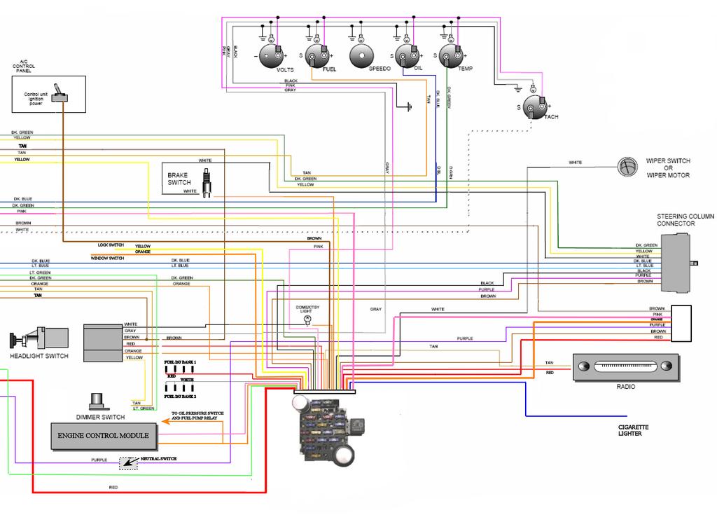
2 Terminals are provided for most connections on your wiring kit. Following the gauge manufacturer s instructions, use the terminals supplied with your gauge kit to connect gauge wires to the gauges. INDICATOR LIGHTS Lt Blue LH dash indicator Dk Blue RH dash indicator Lt Green Hi-beam indicator Connect this wire to the LH dash indicator light. Connect this wire to the RH dash indicator light. Connect this wire to the hi-beam indicator lamp. GAUGE WIRES Dk Green Temperature sender wire Connect to the SENDER location on gauge. Dk Blue Oil sender wire Connect to the SENDER location on gauge. Tan Gas sender wire Connect to the SENDER location on gauge. White Tach sender wire Connect to the SENDER location on gauge. (-) Black Ground Connect to each gauge (ground location) as shown in diagram. Pink 12 volt ignition feed Connect to each gauge (12 v location) as shown in diagram. Grey Instrument lamp feed Connect to instrument lamp, as shown in diagram. ACCESSORY WIRES Black Instrument cluster ground Connect to a GOOD chassis ground. Brown A/C-heat 12 volt feed-fused Connect to the A/C heat-switch (feed in location) Orange (heavy gauge) Blower lead Connect to the A/C-heat switch (power out location) Orange (longer length) Electric fan lead Connect to the Electric fan switch (feed out location) Tan Radio feed - fused Connect to the radio power location. White Wiper Connect to the wiper system
3 DOME / COURTESY LAMP Orange wire- Connect this wire to your dome / courtesy bulb (feed location). White wire- Connect this wire the ground side of the dome / courtesy bulb. The headlight switch ground activates this wire. TURN SIGNAL Purple Turn signal flasher feed Brown Hazard flasher feed Lt Blue Left front turn lead Dk Blue Right front turn lead Yellow Left rear turn / brake lead Dk Green Right rear turn / brake lead White Brake light feed into switch Black Horn button lead Note: Terminals are provided for most connections on your wiring kit. Use the provided terminals and connector to install the following wires: BRAKE LIGHT Orange 12 volt feed to brake switch Connect this wire to one side of your brake switch White 12 volt feed out from brake switch Lt Blue 12 volt third brake light from brake switch White and Light Blue wires are connected together and go to the other available location on the brake switch. IGNITION SWITCH Red 12 volt feed to ignition switch Connect to the BAT location on ignition switch. (white connector) Red 12 volt feed to ignition switch Connect to the BAT location on ignition switch. (black connector) Pink 12 volt ignition feed Connect this to the IGN location on ignition switch. Pink 12 volt ignition feed to dist coil Brown 12 volt accessory feed Connect this to the ACC location on ignition switch. Purple 12 volt feed to starter (via Neutral safety sw) Connect this wire to the ST location on ignition switch.

4 Note: Terminals are provided for most connections on your wiring kit. Use the provided terminals and connector to install the following wires: NEUTRAL SAFETY SWITCH Purple 12 volt feed to starter Each purple wire will go to one side of the neutral safety switch, if applicable. Note: These wires MUST be connected for the vehicle to start! HEADLIGHT SWITCH Red 12 volt feed to switch Connect to the BAT location on headlight switch Orange 12 volt feed in to park/tail Connect to the PARK / TAIL FEED IN location on headlight switch. (commonly found on GM headlight switches) Brown Park / tail feed out Connect to the REAR TAIL LAMP location on headlight switch. Yellow Dimmer feed Connect to the DIMMER FEED location on headlight switch. Gray Instrument lamp feed Connect to the INSTUMENT LAMP location on headlight switch. White Dome / courtesy ground Connect to the switched GROUND location on headlight switch.

5 1. 15A TURN/BACKUP LAMPS 2. 30A IGNITION/COIL 3. 10A ECM 1 IGNITION PWR 4. 10A A/C CONTROLS 5. 10A DOME LIGHT 6. 15A CIGARETTE/RADIO B A GUAGES 8. 20A LOCK SWITCH/RELAY 9. 10A ECM B/FUEL PUMP RELAY A RADIO A WIPER SWITCH/MOTOR A BRAKE LAMPS A HEADLAMPS A INJECTORS B A DASH LIGHTS A HAZARD/HORN A INJECTORS B A PWR WINDOWS
6
7
INSTRUCTIONS. 20 Circuit Wiring Kit Instructions October 2009, Speedway Motors, Inc.
 1 MAIN FUSE PANEL The main fuse panel harness s designed to be mounted under the dash a the firewall in an area close to the steering column. The enclosed representation of the main dash harness shows
Instrument Cluster 30 33B 39B A B C D E F E F G H J. Connector. Circuit Branch #4. Circuit Branch #5. Circuit. Branch #6 150A. Ground.
 16 4D, 43 4B 4A & 130 100 50 39A,B,C 300 4C 4B 4C 107 3C 3D 3C 3G 3B 3F 3A 16A 3G 116 104 93 3B 3D 2E 16A 2C 2D 2B 2A 44 40 27A 40B 115 27 40A,C,E 8A,B,C Mating is plugged into accessory connector Power
-----
 ----- - - -- - - -- - -- - - NOTE: #32 WIRE DOES NOT APPLY TO 8 AND 14 CIRCUIT HARNESSES ELECTRIC FAN #1 TO FAN SWITCH (GRAY) #21 TEMP. GAUGE (GREEN) #2 TO AC SWITCH (BLACK) JUMPER WIRE ALTERNATORS
jegs.com
 Contents Wiring Harness w/ Fuse Panel Installation Instructions Turn Signal Plug w/ Terminals 2 Headlight Plugs 3/4 Grommet 10 ¼ Terminals 4 Ring Terminals 10 Wire Ties Fusible Link 2 Screws & Nuts 2 Plastic
Rear Body 40D 156A 24 17A 151 3D. 8A,8B,8C under hood light. Horn Relay 91
 fuse box as viewed from the wire entry side Mating connector is plugged into Power Accessory connector 40D Rear Body 19 18 9B 30 LH Courtesy Light 40A,D 4D, 43 156B,C 16 16A 4C 3D 3C 16A 3G 4B 3G 116 4A&130
INSTRUCTIONS Circuit Wiring Kit Instructions _2017. Fuse Box Connections. (viewed from underside) 2018, Speedway Motors, Inc.
 2018, Speedway Motors, Inc.") Fuse Box Connections (viewed from underside) 4D 4C 100 50 300 4D 4C 4B 4A 43 107 39 103 3B 2G 104 93 2F 2E 2D 2C 2B 40 69A 102 101 105 2G 2F 2E 3A A 2A B 40A,B 27 69A 106 201, Speedway Motors, Inc. 1 Fuse
Fuse Box Connections (viewed from underside) 4D 4C 100 50 300 4D 4C 4B 4A 43 107 39 103 3B 2G 104 93 2F 2E 2D 2C 2B 40 69A 102 101 105 2G 2F 2E 3A A 2A B 40A,B 27 69A 106 201, Speedway Motors, Inc. 1 Fuse
40A A 40B. Horn Relay Connector. Brake Switch. Third Brake Light. Brake Switch. Brake Switch. Wires. page 3. Rear Body Feed Wires.
 Fuse Box Connections (viewed from underside) 4D 4C 4D 0 50 300 4C 43 7 39 3 6 4 93 A 2G 2F 2E 2D 2C 2B 2G 2F 2E 40 69A 2 1 5 27 69A 3A B 40A,B 11A,B 40A 156 Dimmer Dome Feed page 2 Horn Relay 2D 2 29 40B
INSTRUCTIONS 12 Circuit Wiring Kit Instructions
 Fan 47 9 56 4 7 6 72 40 45 48 5 8 6 Gauge Power Temp Sender Headlight Power Power Radio Constant Power Instruments and Dash Rear of Vehicle Ignition and Lights Fuse Panel & Front of Vehicle Horn Alt Excitor
Mustang Classic Update Series Kit
 accessory rear body 19 9 11 instrument cluster and map 10A, 0 4 3 7 40G 18 30 17A 24 1A 14A 9C 8A instrument cluster 4E 31 3 121 11 401 10A 3 400 30 washer and wiper switch 93A, 93 glovebox, map light,
Classic Update Series
 Classic Update Series 1964-1966 Ford Mustang START HERE! PLEASE READ THIS EFORE STARTING INSTALLATION! This wiring kit is designed for ease of installation. Please read the guidelines below, EFORE STARTING
accessory connection rear body connection 40G 17A instrument cluster and map lamp ground 150A,B 15A 14A Circuit Branch 500A fog lamp switch
 accessory rear body 19 9 11 instrument cluster and map 10A, 0 4 3 7 40G 18 30 17A 24 1A 14A 9 8A instrument cluster 4E 31 3 121 11 33 401 10A 39A 400 30 washer and wiper switch 93A, 94 93 glovebox, map
Headlight Switch Connector. Brake Switch. Lead Wires. Main Power Feed from Starter. Fuse Box Connections (viewed from underside)
") www.americanautowire.com 86-933-0801 TH KT DOE NOT UPPORT TOCK (ORGNAL) GENERATOR. THE DEGN OF THE KT DEGNED TO UPPLY MORE POWER THAN THE GENERATOR ALE TO UPPLY. 16 68A 4D 4C 4D 0 0 0 4C 4 43 7 39 3 Dimmer
www.americanautowire.com 86-933-0801 TH KT DOE NOT UPPORT TOCK (ORGNAL) GENERATOR. THE DEGN OF THE KT DEGNED TO UPPLY MORE POWER THAN THE GENERATOR ALE TO UPPLY. 16 68A 4D 4C 4D 0 0 0 4C 4 43 7 39 3 Dimmer
Classic Update Series
 Classic Update Series 73-79 Ford F100-350 & 78-9 Ford ronco START HERE! PLEASE READ THIS EFORE STARTING INSTALLATION! This wiring kit is designed for ease of installation. Please read the guidelines below,
CLASSIC UPDATE WIRING KIT
 by Randy Irwin 1955-57 CLASSIC UPDATE WIRING KIT Randy Irwin - Technical Writer Randy has been involved in the Chevy parts business for over 25 years. He is a wizard at creating, making and modifying custom
DASH/MAIN HARNESS. NOTE: wires 400 & 401, must be twisted together.
 Electric Speedo Ground 151 Turn Flasher 16A 4 150 8A, Cluster Connections 31 33 30 35 151 (electric speedo) 402 401 NOTE: wires 400 & 401, must be twisted together. 156D, E Panel Dimmer 8A 9, C 2D Headlight
Classic Update Series
 Classic Update Series 67-72 Ford Truck START HERE! PLEASE READ THIS EFORE STARTING INSTALLATION! This wiring kit is designed for ease of installation. Please read the guidelines below, EFORE STARTING your
Headlight Switch Connector. Brake Switch. Lead Wires. Main Power Feed from Starter
 40 3C 40, 2E 2C 2 2F Dimmer witch 12 11 & 11 2C 2 Horn Relay Dome Courtesy feed 40 16 Main Power Feed from tarter 2 12 V attery rake witch rake witch 40 17 17 rake witch Third rake Light Headlight witch
20 CIRCUIT ATO FUSE CENTER INSTALLATION INSTRUCTIONS
 2501 Ludelle Street Fort Worth, Texas 76105 817-244-6212 phone 817-244-4024 fax 800-423-9696 Tech E-Mail: painless@painlessperformance.com Web: www.painlessperformance.com 30003 20 CIRCUIT ATO FUSE CENTER
Classic Update Series
 Classic Update Series 0-4 Ford Falcon and 0- Mercury Comet end view of terminal START HERE! PLEASE READ THIS EFORE STARTING INSTALLATION! This wiring kit is designed for ease of installation. Please read
Classic Update Series
 Classic Update Series 62-65 Ford Fairlane and 62-63 Mercury Meteor end view of terminal START HERE! PLEASE READ THIS EFORE STARTING INSTALLATION! This wiring kit is designed for ease of installation. Please
Headlight Switch Connector. Brake Switch. Lead Wires. Main Power Feed from Starter. Fuse Box Connections (viewed from underside)
") 0 Heller Pl #17 W ellmawr, NJ 0031 6-933-001 TH KT DOE NOT UPPORT TOCK (ORGNL) GENERTOR. THE DEGN OF THE KT DEGNED TO UPPLY MORE POWER THN THE GENERTOR LE TO UPPLY. 16 6 4D 4C 4D 0 0 0 4C 4 4 43 7 39 3
0 Heller Pl #17 W ellmawr, NJ 0031 6-933-001 TH KT DOE NOT UPPORT TOCK (ORGNL) GENERTOR. THE DEGN OF THE KT DEGNED TO UPPLY MORE POWER THN THE GENERTOR LE TO UPPLY. 16 6 4D 4C 4D 0 0 0 4C 4 4 43 7 39 3
Symptom Suspected Area See page Ignition switch is not set to each position. 11.Ignition switch BE 14
 BE2 BODY ELECTRICAL PROBLEM SYMPTOMS TABLE IGNITION SWITCH AND KEY UNLOCK WARNING SWITCH BE0ON18 Ignition switch is not set to each position. 11.Ignition switch BE14 Key unlock warning system does not
pink relay trigger 12v wire - a fused ignition source relay trigger ground wire-to a good chassis ground to component
 relay logic relay trigger 12v wire - to a fused BASIC RELAY WIRING This relay kit is designed f muli-purpose use. a relay trigger ground wire-to a good chassis ground to component amp A B optional included
Classic Update Series
 Classic Update Series START HERE! PLEASE READ THIS EFORE STARTING INSTALLATION! This wiring kit is designed for ease of installation. Please read the guidelines below, EFORE STARTING your installation
Copyright Triple S Customs
 CADILLAC CONCOURS 1994-1997 VEHICLE WIRING Copyright 2002-2004 Triple S Customs WIRING INFORMATION: 1994 Cadillac Concours 12V CONSTANT WIRE RED Ignition Harness STARTER WIRE YELLOW Ignition Harness IGNITION
Camaro Camaro
 Important facts about this kit. 1. The dash panel used in this picture is used by permission of Covan's Classic. We Make Wiring Easy! 2. This kit requires some modification to your original under dash
POWER SOURCE (Current Flow Chart)
") The chart below shows the route by which current flows from the battery to each electrical source (Fusible Link, Circuit Breaker, Fuse, etc.) and other parts. The next page and following pages show the
The chart below shows the route by which current flows from the battery to each electrical source (Fusible Link, Circuit Breaker, Fuse, etc.) and other parts. The next page and following pages show the
Classic Update Series
 Classic Update eries 1966-1977 Ford Bronco TART HERE! We carry many accessories for your p/n 500649 OEM small terminal crimping tool (18-14 gauge) p/n 500523 OEM large terminal crimping tool (12-8 gauge)
WIRE SYSTEM PRO15 ULTRA SMALL 15 FUSE 24 CIRCUIT 118 TERMINAL PANEL WIRE SYSTEM
 TECH UPPORT: 503.693.1918 WIRE YTEM WWW.KEEPITCLEANWIRING.COM PRO15 ULTRA MALL 15 FUE 24 CIRCUIT 118 TERMINAL PANEL WIRE YTEM IMPORTANT: The below instructions are referring to a general installation.
 510564 OPYRIGHT 2013 American Autowire / Factory-Fit Used with express permission of American Autowire / Factory- Fit Page 1 92971174 Rev 0.0 6/18/2015 UNSEALED ONNETORS The connectors, sockets, wires,
Chevy INSTRUMENT CLUSTER CONNECTION KIT WIRING INFORMATION FOR A STOCK CHEVY CLUSTER GREY PINK S + FUEL TEMP S + LAMP LAMP HI BEAM
 WIRING INFORMATION FOR A STOCK 1955-56 CEVY CLUSTER 1955-56 Chevy Terminals and connectors are provided for installation to a stock 1955-56 dash cluster. Pigtail connections are provided for the instrument
ISIS Power Manual and Installation Guide Race Car Replicas- Superlite Coupe
 ISIS Power Manual and Installation Guide Race Car Replicas- Superlite Coupe Table of Contents Overview... 2 System Details... 3 Kit Includes... 3 Technical Specifications... 3 Harness Descriptions... 4
GENERAL INFORMATION PROCEDURE FOR HANDLING CHASSIS/DEALER CLAIMS GOVERNMENT REGULATIONS PAGE. General. Filing a Claim. Disposition of Damaged Parts
 GENERAL INFORMATION 1 PROCEDURE FOR HANDLING CHASSIS/DEALER CLAIMS General All chassis tendered for delivery by the Transportation Company are to be accepted by the Body Company. If a chassis has been
Classic Update Series
 START HERE! PLEASE READ THIS BEFORE STARTING INSTALLATION! This wiring kit is designed for ease of installation. Please read the guidelines below, BEFORE STARTING your installation to guarantee a successful
Symptom Suspect Area See page. 11.Ignition Switch 12.Power Source Circuit. Symptom Suspect Area See page
 BE2 PROBLEM SYMPTOMS TABLE IGNITION SWITCH: BE18204 Ignition switch is not set to each position. KEY UNLOCK WARNING SWITCH: 11.Ignition Switch 12.Power Source Circuit BE15 Key unlock warning system does
WIRE HARNESS INSTALLATION INSTRUCTIONS. For Installing: Part # Circuit Universal CJ Jeep Harness ( ) Manual #90513
 Manual #90513") WIRE HARNESS INSTALLATION INSTRUCTIONS For Installing: Part #10110 12 Circuit Universal CJ Jeep Harness (1975-86) Manual #90513 Perfect Performance Products, LLC Painless Performance Division 2501 Ludelle
WIRE HARNESS INSTALLATION INSTRUCTIONS For Installing: Part #10110 12 Circuit Universal CJ Jeep Harness (1975-86) Manual #90513 Perfect Performance Products, LLC Painless Performance Division 2501 Ludelle
Fuse/Relay Information
 BD 10/24/91 kd 11/12 smk 11/14/91 MC 4/8/92 bd 4/14/92 92 PRELUDE /Relay Information Under-hood /Relay Box 47 46 45 44 43 42 41 40 39 31 49 48 51 50 37 36 35 34 33 32 C941 (To ABS motor relay) 38 C942
Opel Manta/Ascona/1900 Wiring Diagram (Based on using Universal EZ20 wiring harness)
") Opel Manta/Ascona/1900 Wiring Diagram (Based on using Universal EZ20 wiring harness) Index: 1 - Notes, egend, & Shipping Check ist i thru v - Instructions, Dos and Don'ts 2 - Fuse Box Diagram 3 - Front
Opel Manta/Ascona/1900 Wiring Diagram (Based on using Universal EZ20 wiring harness) Index: 1 - Notes, egend, & Shipping Check ist i thru v - Instructions, Dos and Don'ts 2 - Fuse Box Diagram 3 - Front
Classic Update Series
 page 1 *** These are special instructions for connecting your wiring system to a stock instrument cluster. *** NOTE: f you are using after market gauges, follow the instructions included in the 92965220
Classic Update Series
 Classic Update Series *** These are special for connecting your wiring system to a stock instrument cluster. *** (Note: This kit does not support the use of a stock ammeter.) REFER TO THE TTCHED DIGRMS
Classic Update Series
 Classic Update Series *** These are special for connecting your wiring system to a stock instrument cluster. *** (Note: This kit does not support the use of a stock ammeter.) REFER TO THE TTCHED DIGRMS
Classic Update Series
 Classic Update Series *** These are special for connecting your wiring system to a stock instrument cluster. *** (Note: This kit does not support the use of a stock ammeter.) REFER TO THE TTCHED DIGRMS
2009 Model year NPR, NPR HD Gas Electrical Symbols. Symbol Meaning Symbol Meaning Symbol Meaning
 2009 Model year NPR, NPR HD Gas Electrical Symbols 14.1 Symbol Meaning Symbol Meaning Symbol Meaning Fuse Electronic Parts Coil (Inductor), Solenoid Magnetic Valve Fusible Link Resistor Relay Fusible Link
HEADLIGHT AND TAILLIGHT
 BE14 HEADLIGHT AND TAILLIGHT SYSTEM PARTS LOCATION BE15 TROUBLESHOOTING The table below will be useful for you in troubleshooting these electrical problems. The most likely causes of the malfunction are
INTERFACE PART NUMBER NOTES
 2000 Saturn S-Series ALARM REMOTE START WIRING WIRE COLOR LOCATION 12V CONSTANT RED Ignition Harness STARTER YELLOW Ignition Harness IGNITION PINK Ignition Harness ACCESSORY ORANGE Ignition Harness SECOND
Classic Update Series START HERE! Ford Truck. Classic Update Series. p/n OEM small terminal crimping tool (18-14 gauge)
") Classic Update eries 193-19 Ford Truck We carry many accessories for your 193-19 Ford truck p/n OEM small terminal crimping tool (1-1 gauge) p/n OEM large terminal crimping tool (- gauge) TART HERE! PLEAE
Classic Update eries 193-19 Ford Truck We carry many accessories for your 193-19 Ford truck p/n OEM small terminal crimping tool (1-1 gauge) p/n OEM large terminal crimping tool (- gauge) TART HERE! PLEAE
Classic Update Series
 *** These are special instructions for connecting your wiring system to a stock instrument cluster. *** NOT: If you are using after market gauges, follow the instructions included in the 92965220 Gauge
blue 5 wire dash fuse box, white 20 pin plug (E), pin 8 red (key lock); gray (detection) (Tech Doc 1300)
, pin 8 red (key lock); gray (detection) (Tech Doc 1300)") Page 1 of 5 Wiring Information 12 Volts red (40A) + ignition switch, white 6 pin plug, pin 1 Second 12 Volts pink (30A) + ignition switch, white 6 pin plug, pin 5 Starter green + ignition switch, white
Page 1 of 5 Wiring Information 12 Volts red (40A) + ignition switch, white 6 pin plug, pin 1 Second 12 Volts pink (30A) + ignition switch, white 6 pin plug, pin 5 Starter green + ignition switch, white
POWER SOURCE (Current Flow Chart)
") POWER SOURCE (Current Flow Chart) The chart below shows the route by which current flows from the battery to each electrical source (Fusible Link, Circuit Breaker, Fuse, etc.) and other parts. The next
POWER SOURCE (Current Flow Chart) The chart below shows the route by which current flows from the battery to each electrical source (Fusible Link, Circuit Breaker, Fuse, etc.) and other parts. The next
Classic Update Series
 Classic Update Series *** These are special for connecting your wiring system to a stock instrument cluster. *** (Note: This kit does not support the use of a stock ammeter.) REFER TO THE TTCHED DIGRMS
Fuse/Relay Information
 /Relay Information Under-dash /Relay Box C901 (To turn signal/hazard relay) C902 (To blower motor relay) C903 (To rear window defogger relay) C405 C404 C904 (To integrated control unit) C602 (To dashboard
HEADLIGHT AND TAILLIGHT SYSTEM
 BE BODY ELECTRICAL LOCATION E/G Room J/B No. HEAD LH Fuse (w/o Daytime Running Light) HEAD RH Fuse (w/o Daytime Running Light) HEAD LH (UPR) Fuse (w/ Daytime Running Light) HEAD RH (UPR) Fuse (w/ Daytime
Volkswagen Cabriolet DIY Guide Relay/Fuse Diagrams & Electrical System
 Volkswagen Cabriolet DIY Guide Relay/Fuse Diagrams & Electrical System Notes: 1980-1982 cars use ceramic fuses! 1980-1982 cars had a recall for the fuel pump relay. These cars should have a relay bypass
Installation Manual. 12 Automotive Fuse Panel (AFP12) Version 2.2 March 2018
 Version 2.2 March 2018") Installation Manual 12 Automotive Fuse Panel (AFP12) Version 2.2 March 2018 Table of Contents Introduction... 2 What s Included... 3 Installation... 4 Features & Helpful Tips... 9 WAS492 Wire Harnesses...
Installation Manual 12 Automotive Fuse Panel (AFP12) Version 2.2 March 2018 Table of Contents Introduction... 2 What s Included... 3 Installation... 4 Features & Helpful Tips... 9 WAS492 Wire Harnesses...
BMW K1100LT 1993 & Earlier Wiring Diagrams
 BMW K1100LT 1993 & Earlier Wiring Diagrams 1)ABS 2) Motronic with Inputs 3) Motronic with Outputs 4) Instrument Cluster 5) Plus, s, Fuses 6) Reading Light 7) Radio 8) Windscreen 9) Lights with Brake Lights
1962 Wiring Diagram. The Basics Part One. by Bob Mannel
 The Basics Part One 1962 Wiring Diagram by Bob Mannel Most restorers fear the wiring probably since it seems to be the most abused system in our Fairlanes. With cuts, splices, and extra wires running hither
TELORVEK EFI 5.0 Coyote Sequential Fuel Injection System Part # CY-11
 Page #1 TELORVEK EFI 5.0 Coyote Sequential Fuel Injection System Part # CY-11 WIRING INSTRUCTIONS Thank you for purchasing the absolute finest of wiring kits for the Ford Motor Co. Coyote modular engine.
DirectWire Vehicle Information 2016 Kia Soul EV - North America. Page 1 of 4. Wiring Information. Page 1 of 4
 Page 1 of 4 Wiring Information 12 Volts Red (50A) + SJB-Dash Fuse Box, black 3 pin plug (D), pin 2 Second 12 Volts White (50A) + SJB-Dash Fuse Box, black 3 pin plug (D), pin 1 Starter Yellow + SJB-Dash
Classic Update Series
 lassic pdate Series On the following pages, you will find many detailed, specialized instructions that will help you install the dash, cluster, front light, and rear body harnesses from our 70-73 amaro
DirectWire Vehicle Information 2016 Subaru Impreza (Smart Key) - North America. Page 1 of 4. Wiring Information. Page 1 of 4
 - North America. Page 1 of 4. Wiring Information. Page 1 of 4") Page 1 of 4 Wiring Information 12 Volts red (50A) + dash fuse box, rear, brown 9 pin plug, pin 6 Starter pink + Keyless Access Module plug, pin 7 Ignition purple + Keyless Access Module plug, pin 6 Second
Page 1 of 4 Wiring Information 12 Volts red (50A) + dash fuse box, rear, brown 9 pin plug, pin 6 Starter pink + Keyless Access Module plug, pin 7 Ignition purple + Keyless Access Module plug, pin 6 Second
ELEC ELECTRICAL SIGNAL SYSTEM CIRCUIT DIAGRAM SIGNAL SYSTEM EB806000
 EB806000 SIGNAL SYSTEM CIRCUIT DIAGRAM TRICAL 26 3 Main switch 4 Battery 6 Fuse (main) 35 Flasher relay 40 Turn switch 4 Hazard switch 42 Front turn signal light 43 Rear turn signal light 52 Fuse (signal)
Vortec Drive by Cable Electronic Fuel Injection Wiring Harness (P/N HAR-1018) HAR-1018
 HAR-1018") 1998 2002 Vortec Drive by Cable Electronic Fuel Injection Wiring Harness (P/N HAR-1018) HAR-1018 PERFORMANCE SYSTEMS INTEGRATION 170 Oberlin Ave N Suite 13 Lakewood NJ 08701-4548 Ph: 732-444-3277 Email:
1998 2002 Vortec Drive by Cable Electronic Fuel Injection Wiring Harness (P/N HAR-1018) HAR-1018 PERFORMANCE SYSTEMS INTEGRATION 170 Oberlin Ave N Suite 13 Lakewood NJ 08701-4548 Ph: 732-444-3277 Email:
Mustang. Installation Manual. Revision 11/16/10
 1967-1968 Mustang Installation Manual Revision 11/16/10 I Table of Contents TABLE OF CONTENTS...II WELCOME TO THE TEAM OF CLASSIC INSTRUMENTS!... III REMOVE ORIGINAL INSTRUMENT PANEL...1 DETERMINE SPEEDOMETER
Classic Update Series
 lassic Update eries FOR 1967-69 APPLIATION TI AAW KIT O NOT UPPORT T U OF A FATORY AMMTR. A A RPLAMNT FOR T AMMTR W UGGT T U OF A VOLTMTR INTA. TRMINAL KIT 92965220 A BN PROVI FOR YOU TO ONNT TI LUTR KIT
Infinitybox, LLC Addendum to Factory Five 818 Configuration Sheet Installation Guide Table of Contents
 Infinitybox, LLC Addendum to Factory Five 818 Configuration Sheet Installation Guide Table of Contents Overview... 2 Wiring Ignition Input to MASTERCELL... 3 Wiring Ignition Outputs to POWERCELLs... 4
TELORVEK III. WIRING INSTRUCTIONS FOR LT-40 LT-1 Fuel Injection System
 TELORVEK III WIRING INSTRUCTIONS FOR LT-40 LT-1 Fuel Injection System Page #1 Thank you for purchasing the absolute finest of wiring kits for the General Motors fuel injection. We have taken considerable
75/90 FOURSTROKE EFI WIRING DIAGRAM
 75/0 FOURSTROKE EFI WIRING DIAGRAM 0-87725 MARCH 2005 Page 8A-3 75/0 FourStroke EFI Wiring Diagram - Electronic control module (ECM) 2 - Engine water temperature sensor 3 - Ignition coil for cylinder #
GM VORTEC Drive by Wire Electronic Fuel Injection Wiring Harness HAR-1014
 GM VORTEC Drive by Wire Electronic Fuel Injection Wiring Harness HAR-1014 PERFORMANCE SYSTEMS INTEGRATION 170 Oberlin Ave N Suite 13 Lakewood NJ 08701-4548 Ph: 732-444-3277 Email: INFO@PSIConversion.com
Cutlass & F85. Oldsmobile. Wiring Harnesses. item# year description price. Cutlass/F85 PHONE YOUR ORDER FAX YOUR ORDER
 866-405-1367 207 AIR CONDITIONING HARNESSES 06045 1964-1964 AIR CONDITIONING HARNESS, V8 $118.00 09370 1965-1965 AIR CONDITIONING HARNESS, V8 $118.00 09450 1966-1966 AIR CONDITIONING HARNESS, V8 $118.00
blue 5 wire dash fuse box, white 20 pin plug (E), pin 8 red (key lock); gray (detection) (Tech Doc 1300)
, pin 8 red (key lock); gray (detection) (Tech Doc 1300)") Page 1 of 5 Wiring Information 12 Volts red (40A) + ignition switch, white 6 pin plug, pin 1 Second 12 Volts pink (30A) + ignition switch, white 6 pin plug, pin 5 Starter green + ignition switch, white
Page 1 of 5 Wiring Information 12 Volts red (40A) + ignition switch, white 6 pin plug, pin 1 Second 12 Volts pink (30A) + ignition switch, white 6 pin plug, pin 5 Starter green + ignition switch, white
IDENTIFICATION IDENTIFICATION > ENGINE COMPARTMENT FUSE/RELAY CENTER Chevrolet Colorado 3.5L Eng. Vehicle Reference: FUSES & CIRCUIT BREAKERS
 1 of 6 2/1/2015 5:42 PM Vehicle Reference: FUSES & CIRCUIT BREAKERS IDENTIFICATION 2005 Chevrolet Colorado 3.5L Eng CAUTION: When battery is disconnected, vehicle computer and memory systems may lose memory
Section 3 Electrical system
 S40(04-) Section 3 Electrical system Section 3 Electrical system Group 31 Battery System voltage, with ignition off: A newly charged battery may have a higher voltage. 12.5-12.7 V Battery capacity Cold
TELORVEK EFI. 4S. S e. n s tem. a l Fue l I n j e cti
 Page #1 4.63 V &5 TELORVEK EFI. 4S /C S e q uen i t a l Fue l I n j e cti o n Sy s tem MG-05 / MG-05A WIRING INSTRUCTIONS Thank you for purchasing the absolute finest of wiring kits for the Ford Motor
Thank you for purchasing this instrument from Intellitronix. We value our customers!
 Made in America Lifetime Guarantee Thank you for purchasing this instrument from Intellitronix. We value our customers! INSTALLATION GUIDE Corvette Digital Dash Panel Part Number: DP2003 Year Series: 1984-1989
Passat Fitting Locations No. 208 / 1 Edition
 Sivu 1/11 Passat Fitting Locations No. 208 / 1 Edition 02.2007 Relay and fuse assignment From May 2002 Relay locations on 13 position additional relay carrier above relay plate 1 - Radiator fan relay -
Firebird Classic Update Series Kit Firebird
 WNIN: Validate the kit contents with the component list included on this page, before proceeding. This kit is intended to be used in a modified vehicle. Please read this page thoroughly and be sure that
G ELECTRICAL WIRING ROUTING
 G ELECTRICAL WIRING ROUTING Position of Parts in Engine Compartment A 1 A/C Condenser Fan Motor A 2 A/C Magnetic Clutch and Lock Sensor A 3 A/C Triple Pressure SW (A/C Dual and Signal Pressure SW) A 4
DirectWire Vehicle Information 2012 Subaru Impreza - North America. Page 1 of 5. Wiring Information. Page 1 of 5
 Page 1 of 5 Wiring Information 12 Volts white (common 50A) + ignition switch, white 8 pin plug, pin 4 Second 12 Volts white (common 50A) + ignition switch, white 8 pin plug, pin 5 Starter black/white +
headlights [H only] dip switch hi beam flasher pillar interior lights rear interior panel switch C/D cubby A B boot map light LED strip
![headlights [H only] dip switch hi beam flasher pillar interior lights rear interior panel switch C/D cubby A B boot map light LED strip](/thumbs/74/70768506.jpg "headlights [H only] dip switch hi beam flasher pillar interior lights rear interior panel switch C/D cubby A B boot map light LED strip") to Alpine unit exterior lights [S or H or F] FUSE BOX LIGHTS ENGINE ACC reverse light, brake Note: diode (6a 50v) prevents triggering of Alpine backup camera when brake light is closed brake L tail plate
to Alpine unit exterior lights [S or H or F] FUSE BOX LIGHTS ENGINE ACC reverse light, brake Note: diode (6a 50v) prevents triggering of Alpine backup camera when brake light is closed brake L tail plate
pink 5 wire dash fuse box, black 51 pin plug (C), pin 26 red (key lock); gray (detection) (Tech Doc 1300)
, pin 26 red (key lock); gray (detection) (Tech Doc 1300)") Page 1 of 5 Wiring Information 12 Volts gray (30A) + ignition switch, black 6 pin plug, pin 1 Second 12 Volts green (40A) + ignition switch, black 6 pin plug, pin 5 Starter red + ignition switch, black
Page 1 of 5 Wiring Information 12 Volts gray (30A) + ignition switch, black 6 pin plug, pin 1 Second 12 Volts green (40A) + ignition switch, black 6 pin plug, pin 5 Starter red + ignition switch, black
CONFIGURATION DIAGRAMS
 80A-1 GROUP 80A CONFIGURATION DIAGRAMS CONTENTS OVERALL CONFIGURATION DIAGRAM...................... 80A-2 HOW TO READ CONFIGURATION DIAGRAMS.................... 80A-3 ENGINE COMPARTMENT......... 80A-4
TELORVEK EFI 4.6 Sequential Fuel Injection System MK-97A
 Page #1 TELORVEK EFI 4.6 Sequential Fuel Injection System MK-97A WIRING INSTRUCTIONS Thank you for purchasing the absolute finest of wiring kits for the Ford Motor Co. 4.6. This harness works with 1999
AIRSTREAM - BATTERY CONTROL CENTER - Diesel
 P/N 00-00755-000 CAUTION: The Battery Control Center is a centralized power switching, fusing, and distribution center. Power from both the chassis and coach batteries is fed into the box. The full power
CA 421 Installation Instructions
 CA 421 Installation Instructions PROFESSIONAL INSTALLATION STRONGLY RECOMMENDED Installation Precautions: Roll down window to avoid locking keys in vehicle during installation Avoid mounting components
CIRCUIT DIAGRAMS GROUP CONTENTS HOW TO READ CIRCUIT DIAGRAMS BACKUP LIGHT TURN SIGNAL LIGHT AND HAZARD WARNING LIGHT...
 90-1 GROUP 90 CIRCUIT DIAGRAMS CONTENTS HOW TO READ CIRCUIT DIAGRAMS................................. 90-4 JUNCTION BLOCK.............. 90-10............. 90-12 CENTRALIZED JUNCTION........ 90-18 POWER
L PART NUMBER OF CONNECTORS
 L PART NUMBER OF CONNECTORS Code Part Name Part Number Code Part Name Part Number A 1 A/C Ambient Temp. Sensor 90980-11070 B15 Blower Motor Controller (Rear) 90980-11136 A 2 A/C Magnetic Clutch 90980-11271
BOM505 Black Out Module Ford F-150 Contact InterMotive for additional applications
 An ISO 9001:2008 Registered Company BOM505 Black Out Module 2015-2016 Ford F-150 Contact InterMotive for additional applications Introduction The BOM505 module has the ability to eliminate all exterior
BOM507-BC Black Out Module 2017 Ford F250-F550 Contact InterMotive for additional applications
 An ISO 9001:2008 Registered Company BOM507-BC Black Out Module 2017 Ford F250-F550 Contact InterMotive for additional applications Introduction The BOM507-BC module has the ability to eliminate all exterior
TELORVEK III WIRING INSTRUCTIONS FOR NS-93A 4.6 NORTHSTAR Fuel Injection System
 Page #1 TELORVEK III WIRING INSTRUCTIONS FOR NS-93A 4.6 NORTHSTAR Fuel Injection System Thank you for purchasing the absolute finest of wiring kits for the General Motors fuel injection. We have taken
'05- 'Current LS2/LS3 Drive by Cable Electronic Fuel Injection Wiring Harness HAR-1058
 '05- 'Current LS2/LS3 Drive by Cable Electronic Fuel Injection Wiring Harness HAR-1058 PERFORMANCE SYSTEMS INTEGRATION 170 Oberlin Ave N Suite 13 Lakewood NJ 08701-4548 Ph: 732-444-3277 Email: INFO@PSIConversion.com
BODY ELECTRICAL SYSTEM BE 1 BODY ELECTRICAL
 BODY ELECTRICAL SYSTEM BE1 BODY ELECTRICAL SYSTEM BE2 BODY ELECTRICAL SYSTEM General Information GENERAL INFORMATION Wiring color code Wire colors are indicated by an alphabetical code. B = Black L = Blue
INSTALLATION GUIDE Chevrolet Digital Dash Panel Part Number: DP6003 Year Series:
 INSTALLATION GUIDE Chevrolet Digital Dash Panel Part Number: DP6003 Year Series: 1967-1972 * Disconnect the battery before attempting any electrical work on your vehicle. * KIT COMPONENTS One (1) Digital
Position of Parts in Engine Compartment
 ELECTRICAL WIRING ROUTING [5S FE] Position of Parts in Engine Compartment A 1 A/C Ambient Temp. Sensor D 1 Distributor A 2 A/C Condenser Fan Motor A 3 A/C Idle Up VSV E 1 ECT Solenoid A 4 A/C Magnet Clutch
PIMP Ford 5.0 Harness Installation Manual. Part Number: PM-75
 PIMP Ford 5.0 Harness Installation Manual Part Number: PM-75 Ron Francis Wiring 200 Keystone Rd Suite 1 Chester, PA 19013 800-292-1940 www.ronfrancis.com Pre-Installation Notes: This system is designed
1. CAUTIONS WHEN WORKING ON ELECTRICAL UNITS
 841006 013 Fuse and relay 841006 1. CAUTIONS WHEN WORKING ON ELECTRICAL UNITS Remove the negative battery cable from the battery in advance when working on electrical units. Make sure to turn "OFF" the
Classic Update Series
 Classic Update Series *** These are special for connecting your wiring system to a stock instrument cluster. *** (Note: This kit does not support the use of a stock ammeter.) REFER TO THE TTCHED DIGRMS
Fuses. Fuses FUSE BOX LOCATIONS
 FUSE BOX LOCATIONS 206 When a fuse box lid is removed, take care to protect the box from moisture, and refit the lid at the earliest opportunity. Engine compartment - fuse box access: 1. Remove the two
HEADLIGHT AND TAILLIGHT SYSTEM
 BE13 PARTS LOCATION BE14 BODY ELECTRICAL SYSTEM TROUBLESHOOTING The table below will be useful for you in troubleshooting these electrical problems. The most likely causes of the malfunction are shown
INSTALLATION GUIDE Chevrolet Monte Carlo Dash Panel Part Number: DP9002 Year Series:
 Made in America Lifetime Guarantee Thank you for purchasing this instrument from Intellitronix. We value our customers! INSTALLATION GUIDE Chevrolet Monte Carlo Dash Panel Part Number: DP9002 Year Series:
Fuses FUSE BOX LOCATIONS. Engine compartment fuse box
 Fuses FUSE BOX LOCATIONS Engine compartment fuse box 1 2 E90971 Remove the plastic cover by pressing the tabs. The fuse values and locations and the circuits protected are shown on the plastic cover. 3