Electric Bicycle Owner Manual
|
|
|
- Clifford James
- 5 years ago
- Views:
Transcription


1 X-Treme TM Electric Mped XB-610 Electric Bicycle Owner Manual Read this manual cmpletely befre riding yur electric bicycle 1
2 Cntents Table f Cntents Riding Safety 4-6 Prduct Features 7 Package Cntents... 8 Installatin Instructins Frnt Wheel & Brake. 8 Handle Bar Installatin.. 9 Trunk/Pedals/Mirrr Installatin Battery Cnnectin & Initial Charging Instructins 11 Tire Inflatin. 12 Prduct Specificatin Operatin 13 Riding Tip Checklist.. 13 Battery Charging & Safety Basic Maintenance & Schedule Other Infrmatin. 16 Hw T Instructins Hw T Fix Wbbly Handle Bars. 17 Hw T Center Handle Bars. 17 Hw T Remve Hub Mtr 17 Hw T Replace Cntrller Hw T Replace Rear Inner Tube. 18 Hw T Replace Dash 18 Hw T Check Brake Safety Switch Hw T Adjust Drum Brakes 18 Hw T Install Bearings 18 Hw T Replace/Install Thrttle Hw T Align Frnt Frks. 19 Hw T Test Rear Wheel & Cntrller. 19 Hw T Check Vltage
3 Hw T Test Mtr Sensrs Trubleshting Scter Wn t Run, Charger Light Stays Green.. 21 Scter Wn t Run, Charger Light Stays Red & Green 21 Is It My Thrttle Or My Cntrller? Thrttle Vltage Test. 22 Intermitted Pwer Lss N Pwer After Fully Charging, Pwers Only Fr Shrt Distance Use 25 Scter On, Wn t Run. 26 Scter Will Nt Mve.. 26 Charger Hub Mtr Tests Diagrams Wiring Diagram 29 Battery Wiring Diagram 30 Supprt.. 31 DO NOT RETURN TO STORE! D nt use this vehicle fr the first time until yu have inflated the tires t the crrect PSI and cmpletely charged the battery. Failure t fllw these instructins may damage yur vehicle and vid yur warranty. CALL TOLL FREE OR GO ONLINE Fr General Infrmatin r Parts Visit RIDING 3
4 RIDING SAFETY Like any sprt, biking carries the risk f injury and damage. By chsing t ride the electric bicycle, yu assume all respnsibility fr these risks. Thus, yu need t knw and practice the rules f safe and respnsible riding. YOUR INSURANCE POLICIES MAY NOT PROVIDE COVERAGE FOR ACCIDENTS INVOLVING THE USE OF THIS ELECTRIC BICYCLE. TO DETERMINE IF COVERAGE IS PROVIDED YOU SHOULD CONTACT YOUR INSURANCE COMPANY OR AGENT. Safety Basics: D s and Dn ts The D s Always cnduct a Safety Check befre yu ride yur electric bicycle. Be thrughly familiar with the cntrls f yur electric bicycle. Always wear an apprved helmet when riding yur electric bicycle. Fllw the helmet manufacturer s instructins fr fit, use and care f yur helmet. Always keep bdy parts and ther bjects away frm the spinning wheels f yur electric bicycle. Always wear shes that will stay n yur feet and will stay n the flrbard. Wear bright, visible clthing that is nt s lse that it can catch n mving parts f the electric bicycle r bjects at the side f the rad r trail. Think abut yur speed, and keep yur speed cnsistent with safe perating cnditins. The Dn ts Never ride with headphnes. They mask traffic sunds, distract yu frm cncentrating n yur surrundings, and their wires can tangle in the mving parts f the electric bicycle, causing yu t lse cntrl. Never carry a passenger. The maximum carrying capacity is 300 lbs. Never ride bareft r wearing sandals. Dn t jump with yur electric bicycle. It puts great stress n everything frm frame and frks t drive train. Riders wh insist n jumping their electric bicycle risk serius damage t their electric bicycle as well as t themselves. Never carry anything which bstructs yur visin r yur cmplete cntrl f the electric bicycle r which culd becme entangled in the mving parts f the electric bicycle. Never hitch a ride by hlding n t anther vehicle. 4
5 Never ride yur electric bicycle while under the influence f alchl r ther drugs. If pssible, avid riding in bad weather, when visibility is bscured, at dusk r in the dark, r when yu are very tired. Each f these cnditins increases the risk f accident. Never allw children t ride. Never allw thers t ride withut reading and understanding these instructins. Operating Reminders and Suggestins Review all instructins carefully befre riding the electric bicycle. Fllw all rules and regulatins in yur area fr perating a mtrized bicycle. Obey the same rad laws as all ther rad vehicles, including yielding the right-f-way t pedestrians, and stpping at red lights and stp signs. Ride predictably and in a straight line. Never ride against traffic. Ride defensively. T ther rad users, yu may be hard t see. Cncentrate n the path ahead. Avid pthles, gravel, dirt, wet rad, il, curbs, speed bumps, drain grates and ther bstacles. Be alert fr unexpected events, such as pening car drs r cars backing ut f cncealed driveways. Be extra careful at intersectins and when preparing t pass ther vehicles. Dn't carry packages r passengers that will interfere with yur visibility r cntrl f the bike. Dn't use items that may restrict yur hearing. Maintain a cmfrtable stpping distance frm all ther riders, vehicles and bjects. Safe braking distance and frces are subject t the prevailing weather and rad cnditins. Wet Weather Riding Wet weather impairs tractin, braking and visibility, bth fr the rider and fr ther vehicles sharing the rad. The risk f accident is dramatically increased in wet cnditins. In wet weather yu need t take extra care. In wet cnditins, the stpping pwer f yur brakes (as well as the brakes f ther vehicles sharing the rad) is dramatically reduced. This makes it harder t cntrl speed and easier t lse cntrl. T make sure that yu can slw dwn and stp safely in wet cnditins, apply yur brakes earlier and mre gradually than yu wuld under nrmal, dry cnditins. Decrease yur riding speed, avid sudden braking, and take crners with additinal cautin. Keep in mind that there is a direct, but inverse, relatinship between speed and cntrllability. Be mre visible n the rad. Wear reflective clthing and use safety lights. Pthles and slippery surfaces such as lane markings and train tracks all becme mre hazardus when wet. Night Riding A rider is very difficult fr mtrists t see at dusk, at night, r at ther times f pr visibility. If yu must ride under these cnditins, check and be sure yu cmply with all lcal laws abut 5
6 night riding; fllw the Rules f the Rad, and take the fllwing precautins: Make sure that yur electric bicycle is equipped with crrectly psitined and securely munted reflectrs. Make sure yur clthing r carg des nt bstruct a reflectr r light. Wear light clred, reflective clthing and accessries, any reflective device r light surce that mves will help yu get the attentin f appraching mtrists, pedestrians and ther traffic. Ride slwly. Avid hazards, such as pthles and curbs. Avid areas f heavy traffic, dark areas, and rads with higher speed than limited. If pssible, ride n rutes already familiar t yu. Ride at night nly if necessary. Slw dwn and use familiar rads with street lighting, if pssible. Other Imprtant Reminders The battery des NOT require deep discharging. If yur electric bicycle is put int strage, re-charge its battery at least nce every 90 days. D nt stre yur electric bicycle in direct sunlight fr an extended time. Stre yur electric bicycle in a dry place. Expsing yur electric bicycle t rain, snw, r ther precipitatin may result in damage. 6

7 Prduct features 7
8 Package Cntents: Electric Bicycle 48V 20AH Charger Left & Right Mirrrs Frnt Tire Frnt Fender Left & Right Ft Pedals Ignitin Keys Ft Pad Trunk User Manual Preparatin fr Assembly A. Remve the cardbard cartn expsing the steel frame crate. B. Remve the blts hlding the tp and side center pst n the steel frame. Remve the tp & center pst and set aside. See page 9 number 2-1 C. Bend the frnt and back frame sides dwn t the grund s they are ut f the way. D. T assist with assembling the frnt wheel remve the wire ties hlding the frnt axle (leave the rear axle wire ties cnnected fr stability). E. Remve all prtective packaging. F. Remve Axle frm frnt frk & shipping crate and set aside, d nt discard. G. Find a slid square bject abut 10 t 12 high and with assistance raise the frnt f the bike and place it under the flr bard battery cmpartment. This will allw fr easier frnt wheel installatin. H. Remve blt frm handle bar stem and place handle bars nt steering shaft. This will give extra brake cable length fr installing the brake drum n the wheel and frk. I. Remve the screw hlding the frnt brake assembly n the frk. Install frnt wheel and brakes per instructins belw Page 8 8


 3.")


9 1.) INSTALLATION OF FRONT WHEEL AND BRAKE. 1. Insert brake hub nt wheel as shwn abve. 2. Slide wheel int frnt frks being sure t align brake hub bracket with right side frk. See image belw. (When sitting n bike, frnt brake is n riders left side f frnt wheel) 3. Slide axle thru left frk, then spacer befre inserting it int the left side f frnt wheel. 4. Secure with nut n right side (brake side) and tighten securely 5. With frnt wheel installed prceed t munt the frnt fender. The furth screw fr the fender is in the plastic bag with the trunk blts. 9
 f the handlebars and secure with nut n the")


 Tw pin cnnectr with ne Black wire n instrument panel cnnects t tw pin cnnectr with ne Grey wire n wire harness.")
10 2.) HANDLEBAR INSTALLATION 1. Lcate and remve the handlebar blt, washer & nut as shwn. Fr access t the nut n the back side, turn the handlebars fully t the right. 2. Slide handlebars ver pst in the crrect psitin, then insert the blt & cncave washer int the frnt (speedmeter side) f the handlebars and secure with nut n the back (riders side). Cncave washer shuld be partially inserted int the handlebar and make cntact with internal pst t be tightened prperly and securely. 3. Using tw 14mm wrenches place ne n the frnt blt frm the tp and the secnd n the nut by reaching up frm the bttm under the fairing. Carefully tighten checking t cnfirm cncave washer is placed crrectly in the slt. Cnnecting Instrument Panel The instrument panel is lcated in the seat strage cmpartment, use key t pen. 1) Six pin cnnectr n instrument panel cnnects t six pin cnnectr n wire harness n tp f the handlebars. 2) Tw pin cnnectr with ne Black wire n instrument panel cnnects t tw pin cnnectr with ne Grey wire n wire harness. (Sme unit may have ne extra cnnectr n the instrument panel. If it has a tw pin female cnnectr with Red and Purple wires it is left empty and nt used.) ** Befre munting the instrument cluster cnfirm all wire cnnectins are firmly tgether and cnnectr cvers placed ver terminals securely. 10
")


11 3-5.) TRUNK/PEDALS & MIRROR INSTALLATION 3. Attach trunk t back carg rack using the fur (4) enclsed blts/nuts & washers. Secure t rack with the washers & nuts n the underside. 4. Attach left & right ft pedals accrding t crrect side by lining up pedal with bearing n pedal shaft and snap int place. 5. Mirrrs are lcated inside the trunk. Screw left & right mirrrs int place and adjust t apprpriate riding psitin. ***Mirrrs install with an upward angle; D nt try t frce hrizntal. 11

 TIRE INFLATION Finally, inflate bth tires t the minimum recmmended tire pressure depending n the number f riders that will be using the bike.")
12 6.) BATTERY CONNECTION & INITIAL CHARGING 1. Remve battery pack and lcate plug. 2. Plug battery wire int battery pack and reinstall battery pack under ft plate. 3. IMPORTANT: Cmpletely charge battery fr a maximum f 8 hurs befre use. DO NOT CHARGE FOR MORE THAN 8 HOURS AS THIS CAN DAMAGE BATTERIES. Main Fuse Main fuse is lcated inside battery case under flr mat. 7.) TIRE INFLATION Finally, inflate bth tires t the minimum recmmended tire pressure depending n the number f riders that will be using the bike. Recmmended tire pressure is between PSI. We d nt recmmend filling tire beynd 45 psi. * Be sure t check all nuts, screws and terminals n the bike fr tightness and prper fit befre riding. 12
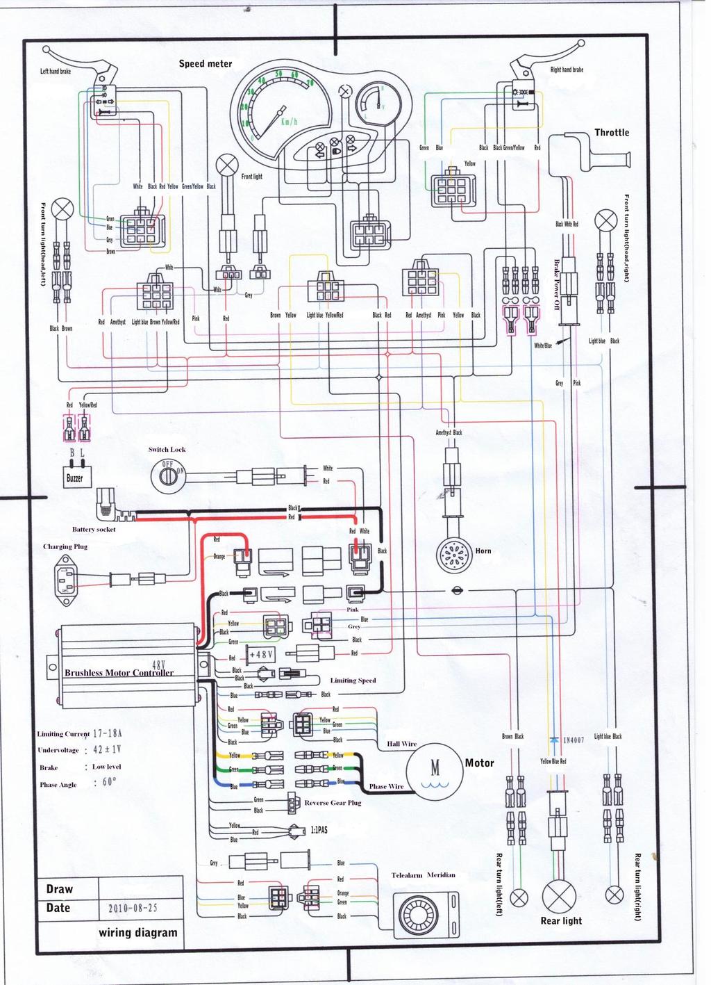
13 Prduct Specificatins 1. Wire diagram 2. Specificatins Battery Vltage 48Vlt Dc,20Ah Mtr Wattage 600W Wheel Size 16 inch Tp Speed 35km/h Charging Time 6-8h Distance f full charge 50km Battery charging cycles <300 times Max rider weight 300lbs Tw rider Yes Left and Right Indicatrs Yes Rear View mirrrs Yes 13

14 Operatin Yur new Electric Bicycle/scter is a revlutinary new transprt prduct using a sealed lead acid batteries and a super high efficiency electric hub mtr designed t ASSIST in the prpulsin f yu and yur bicycle. It is imprtant t nte the fllwing riding guidelines t ensure yu get the best pssible experience frm yur electric bicycle. Riding tip checklist A) When starting ff frm a stand still pedal the bicycle up t speed then engage thrttle fr best results. B) On inclines pedaling will be required t maintain mmentum. C) Remember perfrmance f the bike is directly related t weight f the rider and any baggage/lad tgether with the charge in the batteries. D) Ensure batteries are fully charged prir t riding. E) Never let the batteries fully discharge. This will reduce battery and bike perfrmance. F) If yur bike is equipped with lights we recmmend yu ride with them switched n at all times t increase visibility fr yu and ther rad users. Battery Charging and & Battery Safety Charging figure 1-4 Charging (see figure 1-4) A. Ensure bike is turned ff and key is remved. B First cnnect t the battery charger t the charging scket lcated belw the frnt f the seat. (Optinally, yu can als remve the battery pack and charge utside f the bike if preferred) C. Then insert the pwer plug n the battery charger int 110v pwer utlet. 14
15 D. While charging the light n the battery charger will illuminate Red. E. When fully charged the light will illuminate Green. F. NEVER CHARGE FOR OVER 8 HOURS. DAMAGE MAY OCCUR TO BATTERY G. Always charge the bike in a well ventilated area prtected frm bad weather & wet cnditins. NEVER CHARGE THE BIKE INSIDE YOUR HOME ONLY CONNECT THE BATTERY CHARGER LEAD TO THE BIKE CHARGER INLET. NEVER CONNECT ANY OTHER POWER SOURCE TO THE BIKE CHARGER INLET. Battery Charging Safety Ntes 1) While charging the Battery, keep the key switch OFF. 2) Verify that yu are using the crrect charger fr yur vehicle, and that the charger input pwer is cmpatible the huse current in yur area. 3) Keep the charger and battery away frm water t prevent electrical shck and shrting. The charger is intended fr indr use nly. 4) Read the charger label t learn abut the charger indicatr lights, and their meanings. 5) Generally, a shrt drive will require a shrt time t re-charge, and a lng ride will require a lnger time. A cmplete (90%) discharge may require 6 hurs t recharge. T prevent electrlysis (battery fluid lss by hydrgen generatin,) d nt charge fr lnger than eight hurs. WARNING D nt place the battery near heat r fire. D nt expse the chargers t water. Maintenance ----Basic 1. Yur bike cmes with a 30amp fuse, pre-installed at the factry and is lcated inside the battery bx. 2. Clean Chain Regularly. 3. Ensure Tires are inflated t PSI. 4. Adjust Brake tensin via adjusting screws lcated at Brake lever r n Brake cntrl lever. 5. Ensure regular servicing accrding t the schedule. 6. D nt attempt t change any electrnic cmpnents except changing light bulbs. 7. DO nt attempt t mdify, pen r perfrm maintenance n the Hub Mtr. 8. Any attempt t mdify electrical cmpnents will vid the warranty unless specifically requested by a X-treme Scters representative. 15
16 Maintenance ----Schedule Service Interval Daily Mnthly Every 6 Yearly Mnths Inspect Tires fr wear and Yes Yes Yes Yes cnditin and inflatin Check and adjust Brake Yes Yes Yes Yes Check peratin f all lighting Yes Yes Yes Yes and hrn devices. Replace glbes if necessary Test Battery Capacity Yes Yes Replace Wheel Baring Grease Yes Full Brake Pad Change ver Yes Check cnditin and trque settings f wheel nuts and suspensin frks Yes Yes Other Helpful Instructins Pedals 1. Use a pedal wrench f 16mm spanner t tighten pedals. 2. Check and tighten pedal crank blts with 14mm scket. Tires 1. Inflate tire using a pump t 35-45psi. Remember lwer tire pressures will negatively impact perfrmance by causing t much resistance, but ver inflating may cause the tube t burst. Chain 1. Give the train a light drp f bicycle chain il r sewing il. D nt use RP7 type lubricants. 16
17 Hw T Fix Wbbly Handle Bars 1. Remve the instrument panel by taking ut the six (6) screws frm the bttm and discnnecting the wire cnnectrs 2. Lk at the blt that clamps the handle bars t the steering stem: is the gld spacer seated crrectly? 3. Tighten the blt by using tw 14mm wrenches ne frm abve n the frnt f the blt and the ther by reaching up under the wheel well t hld the nut in place while the frnt ne tightens the bld snuggly. 4. Check handle bars fr secure fit. If still wbbly remve blt, reset handle bars and tighten. Having the blt securely tight will eliminate the handle bars frm wbbling. Hw T Center Handle Bars 1. First remve the dash. Yu shuld nt have t remve it cmpletely, but at least split it s yu may access the space in the center f the handle bar. 2. In the center f the handle bar yu will see the head f a small blt. 3. Lsen this blt up slightly until the handle bars can mve t the crrect psitin. 4. When the bars are aligned prperly tighten the blt. 5. Reassemble the dash pieces. Hw T Remve Hub Mtr 1. Remve the tw nuts n each side f the mtr. 2. Remve brake adjustment nut and remve brake cable frm brake hub. 3. Remve brake hub lck nut where it attaches t frame. 4. Remve axle lck plate by remving the #10 blt n each side. 5. Fllw the mtr wires up under the rear fender, it will cnnect t quick discnnects and unplug the cables. 6. Fllw the chain up t the pedal sprcket and mve the chain ff f sprcket. Use the pedals t turn until the chain is ttally ff f the sprcket. Then remve the sprcket ff f wheel sprcket. 7. Remve wheel mtr frm scter. Hw T Replace Cntrller 1. Remve the Battery Pack frm the scter and set aside until new cntrller is installed. 2. Open the seat and remve the fur (4) seat barrel screws, tw (2) near the Latch and tw (2) in Frnt. 17
18 3. Remve entire Seat and Seat Barrel frm scter. 4. Unscrew yur ld cntrller frm the frame - Leave wires cnnected. 5. Munt the New Cntrller in its lcatin. 6. Transfer One Cnnectr at a time frm the ld cntrller t the new cntrller. 7. Re-install Battery. 8. With drive wheel nt tuching any surface Test Run and cnfirm all functins are wrking. 9. Re-assemble and test ride. 10. This is als a gd time t perfrm the recmmended maintenance as listed in the Handbk. Hw T Replace Rear Inner Tube 1. Remve the seat and seat barrel. 4 screws need t be remved, 2 by the hinge and 2 dwn inside and remve frm scter. 2. Fllw the wire cming ut f side f mtr and cut the tie straps leading up the cntrller. 3. Remve the wheel nuts and remve the brake adjustment nut and remve the wheel. 4. Let all air ut f tire and use either a tire wrench r cuple dull screw drivers t remve tire bead frm ne side f rim t remve and install the tube. 5. Install in reverse rder make sure that the mtr nuts are n extremely tight, use a 2 1/2' crescent wrench t tighten them. Hw T Replace Dash 1. First remve the fur screws n the black gseneck cver belw the handle bars. 2. Then yu will be able t remve the headlight faring. It will slide dwn and frward. 3. Unhk the wires t the headlight and set the headlight faring aside. 4. Then yu remve 5 screws n the back f the handle bars. 5. There is 1 screw n the frnt f the handle bars, als remve that. 6. Remve the mirrrs frm the scter by turning cunterclckwise. 7. Nw the handle bar faring is ready t be remved, Start n the left side by where yu remved the mirrr. Gently pull the frnt and back f the handle bar fairing apart. It shuld snap apart fairly easily. Wrk yur way acrss until the tp is cmpletely apart. 8. Remve and replace. 9. Reverse the rder t reassemble. Hw T Check Brake Safety Switch 1. First remve frnt fairing and check the thrttle cnnectr and brake cnnectrs fr lse 18
19 cnnectin. Tug n each wire t make sure its lcked int the cnnectr. 2. Open seat and remve the 4 blts that attaches the seat barrel t the scter. 2 blts n each side f the seat latch and the ther 2 are in dwn in bttm frnt f seat barrel. Lift ff the seat and seat barrel as ne piece. 3. Lcatin f brake safety cnnectin: Yu shuld see a bx with several wires cming ut f it. Yu will als see these wires g int quick discnnects and lcate a 4 wire plug. There will nly be ne and n the cntrller side f the cnnectr the wire clrs are: Yellw, Red, Black and Green. On the ppsite side the clrs are Blue, Green with Yellw stripe, Gray and Green. Unplug the cnnectr and lcate the Blue wire, n the ppsite side f the wire ges int the male cnnectr we will need t unlck the gld pin t remve the wire frm the cntrller. Hw T Adjust Drum Brakes 1. Lsen the brake handle adjustment n handlebars t fully utward. Lcate the brake cable adjustment screw and screw this in all the way. 2. Fllw yur brake cable t the brake caliper. There will be a small nut hlding the metal cable t the caliper arm. Lsen this nut, mve the brake arm while hlding the cable tight until the brake just starts t drag when the tire is turned ff the grund. Tighten the lck nut back dwn nt the cable. 3. Next fine tune the adjustment by screwing the cable tensin screw utward t pull n brake line until prper braking is achieved. 4. Lck this psitin dwn by tightening the nuts. 5. Avid adjusting brakes n handlebars because there is a safety switch built int the handles t kill mtr while using the brakes. Hw T Install Bearings 1. Remve the rear wheel. 2. Remve the ld bearing. T d this, yu will need t insert smething, like a screw driver, frm the ppsite side and simply push it ut. 3. Put the new bearings in. Yu will want t use smething like a rubber mallet s yu d nt crack the bearings. Set the wheel n a flat, absrbent surface, like a wrk bench. Tap the bearing int the wheel evenly. 4. Re-install the tire and test ride. Hw T Replace/Install Thrttle 1. Remve six Phillips head screws frm handlebar cver. 19
20 2. Unplug six pin and ne pin cnnectrs frm instrument panel. 3. Fllw wire frm thrttle husing t white cnnectr and unplug, (shuld be 3-pin cnnectr with black, red and white wires). 4. Lsen small allen head blt frm thrttle husing and slide thrttle frm handlebar. Hw T Align Frnt Frks 1. Remve the dash n the backside. Find the 12mm blt in the center f the handlebars and lsen it. 2. Take a hammer and hit this blt. Stand with the frnt tire between yur legs. Hld the tire with yur legs and turn the handlebars int psitin. 3. Tighten the 12mm blt and reassemble the dash. Hw T Test Rear Wheel & Cntrller Place scter up n center kickstand, turn scter ignitin in the "ON" psitin. Spin rear wheel by hand and check t see if it falls in ne f the fllwing cnditins: A.) Wheel spins with slight resistance Cntrller culd need replaced B.) Wheel spins hard like brake engaged Cntrller and mtr culd need replaced C.) Wheel spins Jerky Cntrller and mtr culd need replaced Hw T Check Vltage Tls Needed: Multi-meter t read VDC First be sure the battery cnnectr frm the scter is firmly attached t the battery case. Leave all cnnectrs cnnected when measuring the vltage by sliding yur meter prbes int where the wires g n the backside f the cnnectrs. Battery Pwer vdc per battery min = +50vdc t turn n the cntrller. 1. Acrss the large Red & Black wires cming ut f the cntrller is main pwer leads. Shuld have +50vdc here. Thrttle measurement: Leave cnnectr cnnected while measuring. 1. Lcate the thrttle cnnectr n the cntrller, it will be a red cnnectr with 3 wires cming ut f it f RED, BLACK & GREEN. Put yu Black meter prbe in n the black wire. Insert Red prbe in n the red wire and turn the scter in the ON psitin. These wires are the 5v 20
21 supply t the thrttle, and shuld be within this range ( ) Nw remve the red prbe frm the Red wire and put it n the Green wire and need 2 recrded readings n thrttle and 100% thrttle. Shuld be 0 Thrttle and 100% Thrttle. 2. Ignitin Check: Place Black meter prbe n main BLACK battery wire n the cntrller. Lcate the 2 wire cnnectr with Orange and Blue wire frm cntrller. Insert Red meter prbe n Orange wire and shuld have +50vdc. Insert Red meter prbe n the Blue wire and shuld nly have +50vdc when the ignitin key switch is in the ON psitin. 3. DC/DC cntrller check. This is the smaller silver bx under the headlight assembly and has 3 wires cming ut f it. Red & Black wire shuld have 48vdc with the key n, and Yellw and Black shuld have 12vdc befre and after the Glass Fuse. The DC/DC Cntrller pwers accessries like the lights, hrn etc. Hw T Test Mtr Sensrs Srt ut the mtr's wiring. There is eight wires ttal, r leads, running frm the mtr t the cntrller. Three larger wires pwer the mtr and are larger (16 AWG): Green, Blue, and Yellw. Tw wires pwer the sensrs and are smaller: Red and Black. And three wires cnnect the sensrs t the cntrller: Green, Blue, and Yellw. All 5 small wires are cnnected t ne white quick discnnect. Fr this prject, we are cncerned nly with the smaller wires f Green, Yellw and Blue. Nw, there are tw methds used t determine a bad cnnectin r which f the three sensrs have failed. Bth require the mtr t be fully assembled. The first is t simply run the mtr while ne sensr lead is discnnected, refer t sectin-a belw n hw t d this, then again fr the secnd lead, and a third time fr the last lead. If ne sensr is dead (and that's yur nly prblem), yu'll see that discnnecting ne r the ther f the gd sensrs prevents the mtr frm turning altgether, while discnnecting the bad ne has n effect at all--it still sputters. If that didn't wrk, try this secnd methd. It is mre cmplex, but useful t identify a bad cntrller vs. the mtr, and mre nuanced issues r prblems stemming frm multiple failures. Remve the 3 small wires frm the 5 wire cnnectr leaving the red and black wire attached. While the mtr is cnnected t the cntrller, pwered, and at rest--r, alternatively, pwered 21
22 with +5 vlts frm a wrkbench pwer supply--set up a multi-meter t mnitr the sensr's utput n ne f the 3 wires. Cnnect the Black Vltmeter Lead t the small black wire by inserting the prbe in where the wire ges int the cnnectr. Attach the Red Vltmeter t ne f the 3 wires t be tested. IMPORTANT: DO NOT let any f the small wires tuch each ther r will blw the sensr. Turn the mtr by hand very slwly while watch the vltmeter. It shuld pulse t 5vdc when active and 0vdc when nt. Repeat this step fr ther 2 wires. If all three wires Green, Blue and Yellw pulses 5vdc then the mtr is gd and cntrller is bad. Sectin-A: D nt have scter pwered up. Lcate the white quick 5 wire cnnecter leading frm the cntrller t the mtr and unplug cnnectr. With a small ice pick r large needle inserted t unlck the lck tab ne f the gd pins. And pull the wire ut f the cntrller and recnnect the cnnectr. Tape ff the gld pin s yu can prtect it. Return t abve instructins abve. Trubleshting: Scter Wn t Run, Charger Light Stays Green When yu plug yur charger int yur scter and the wall utlet the charger light stays green. This is telling me that smewhere between charger scket, cntrller, fuse hlder and batteries yu have an pen circuit. Please remve the flr plate and check the wires in this area. Yu may find a wire that is nt cnnected, a cnnectr that is nt pushed tgether prperly r a fuse hlder that is nt letting the fuse cnnect prperly. Trubleshting: Scter Wn t Run, Charger Light Stays Red & Green When yu plug yur charger int yur scter and the wall utlet the charger light stays green. This is telling me that smewhere between the batteries, fuse, and charger scket yu have an pen circuit. Please remve the flr plate and check the wires in this area. Yu may find a wire that is nt cnnected, a cnnectr that is nt pushed tgether prperly r a fuse hlder that is nt letting the fuse cnnect prperly. Trubleshting: Is It My Thrttle Or My Cntrller? (These tests require a digital VOM) Mst E-scter thrttles use 'Hall-effect' devices, nt ptentimeters (rhestats). A Hall-effect device is a chip that respnds t a mvable magnet. If yu have a digital VOM (I wuld nt use an 22
23 analg resistance meter f any kind, as it culd damage the chip if it's a Hall-effect chip), yu can test whether it's a ptentimeter r nt. If it is, yu shuld get 5K hms acrss red and black, and f curse, 0-5K frm red r black t the third wire (usually green r yellw). If it isn't, yu'll get readings in the meghms in ne directin and n cnnectin in the ther in sme cases. A better test if yu have a digital VOM, is t push the prbes int the back f the thrttle cnnectr at the cntrller while it is cnnected. Turn the scter n, and perate the thrttle. Yu shuld get near zer t near 4 r 5 vlts between the black and third wire (green r yellw). These vltages wrk fr mst scters, but nt all. Sme thrttles use 0-24 vlts, and sme use a negative vltage (the thrttle 'sinks' current). Yu shuld als check the brake inhibit switch (there shuld be a wire cable cming frm yur brake handle), t see if it is making and breaking cntinuity. The brake inhibit switch turns the thrttle ff when yu put the brakes n. It functins like a 'kill switch' shuld anything g wrng. Yu shuld als test the key switch in the same way. Yu can test the mtr by jumping frm the batteries t the mtr, but be aware that it will make a large spark, r yu can test the vltage at the mtr cnnectr while turning the rear wheel backwards. The mtr shuld generate a small negative vltage that varies with the speed it is turning. A smell test is als cnclusive prf that yu have a damaged cntrller r mtr. If yu can get yur nse clse t ne r the ther and it smells like badly burnt brccli, it's burnt ut. Of curse it culd als be burnt ut and nt smell, but if it smells it's burnt ut. Trubleshting: Thrttle Vltage Test Fllw thrttle wires until yu find its white cnnectr. Yu will be testing the Red, Green, and Black wires. Set yur meter t test DC vlts. Blck rear wheel ff the grund s scter will nt take ff. Turn the scter n. Place the red meter test lead n the Red wire and the black meter lead n the Black wire. The meter shuld measure +5 vlts. Nw place the meter red lead n the Green wire. With ut turning the thrttle yu shuld read arund +0.8 vlts. Nw turn the thrttle wide pen. Yu shuld nw read arund +4 vlts. If everything else pwers up n the scter and yu d nt have +5 vlts between the Red and Black wire the cntrller is bad. If yu did nt get the +.8 t +4 vlts then the thrttle is bad. Trubleshting: Intermitted Pwer Lss While ding each f the steps yu are t g and test drive the scter t make it cutut like it was ding. Yu will need a vltmeter fr electrical readings and will als require a pwer crd that is 23
24 used n a cmputer which has the same type f plug that will plug int the charger prt, with a wire length f 2' and cut wire and discard the rest. What we are ging t d is attach the vltmeter leads t this cmputer wire and plug int the scket t watch actual vltage while riding and munting the vltmeter is a spt and secure it s it desn't mve but be able t watch it while n test runs. I have prvided a drawing f this called vltmeter cnnectin.jpg abve. 1. First pull up battery pack and pull the main pwer crd ut f scket n battery pack t kill all pwer. 2. Unplug the Large Red and Orange 2 wire cnnectr n cntrller. This cnnectin is fr the Ignitin switch test, n the side that has the Red and white wire by lking dwn inside yu will see 2 silver pins and there is a little tab that yu push twards the pin and the wire will cme ut f the cnnectr. Take a piece f wire abut the same dia. as the range wire apprximately 4" lng and strip the insulatin ff each end abut 3/4" lng. Take ne end f the jumper wire and wrap arund the pin where the wire is crimped n t. Then the ther end f jumper t the white wire and reinsert it back int the white cnnectr. Yu may need t pull ut the little lck tab s it will lck int place. Reattach the cnnectr back nt the cntrller, as shwn in my drawing abve. Plug yur crd int the charger scket fr the vltmeter, just set the seat and seat barrel in the scter withut blting it. When ready plug the main battery crd in bttm f battery and turn yur vltmeter n. The scter will cme as sn as yu plug it in and may spark a little this nrmal. G fr test ride. If yu get same results f still kicking ut, just unplug main pwer crd and plug in t turn it back n. Trubleshting: N Pwer In this situatin we will assume that the battery has been charged r allwed t stand fr several hurs (a battery will nrmally self-charge up t a pint and make the scter pwer up fr a fair distance). There are generally tw main suspects: 1. First suspect is a lse r brken cnnectin. Take the tp r deck ff t see the wiring and inspect it fr any lse r brken cnnectins n the battery, switch, cntrller, etc. 2. Secnd pssibility is the cntrller bx has failed. Since the cntrller is the heart f the system it can fail in many ways t prevent current frm being supplied t the mtr. 3. Other less likely suspects can be: A battery that is cmpletely pen, supplying n current and pssible even testing as having n vltage. It can be very briefly shrted with a wire t see if an arc is prduced, revealing current is present. See Belw fr mre advice n batteries. It is als pssible t have a bad brake lever r thrttle since bth have wiring and switches r 24
25 variable cntrls. The brake lever has a pwer cut-ff switch. The thrttle variably cntrls the speed f the scter. The scter On/Off switch can be defective. Withut a gd switch the scter has n pwer, but the test f this is the pwer light. Des the pwer light cme n when the switch is activated t the On psitin? Trubleshting: After Fully Charging, Pwers Only Fr Shrt Distance Use 1. Suspect the battery charger r the battery as the primary cause f shrt distance riding after a lengthy r full charge. If yur battery charger des nt have charging indicatr lights then yu may nt be charging the battery at all if the charger is defective. 2. The battery may be self-charging t nly abut 60% n its wn. If the battery is getting ld then it may nt be able t hld a full charge and the battery will need replacement. When suspected yu can very briefly arc acrss the battery terminals with an insulated wire t see if it prduces a nice arc.. It is als pssible t test sme individual battery 12 vlt cells using 12 vlt mtrs r lights that will shw yu the available current capability. Is the 12 vlt light dim n a charged battery? Des the 12 vlt mtr run slwly when cnnected t the cell? Similar type tests can be perfrmed using a 24 vlt battery cell, t. WARNING! Batteries cntain acid that can explde, r the vaprs ignite frm an arc. Batteries prduce current and vltage that can burn yu when a shrted circuit ccurs. Be abslutely sure yu knw what yu are ding befre trying any tests t eliminate a cmpnent frm cnsideratin f being defective!!! 3. Yu can take the battery t a shp capable f testing the battery under a laded cnditin. Fully charge the battery and carefully remve it. Let a technician determine the cnditin f the battery fr yu. 4. We recmmend a high quality Battery Charger as sld n ur scter parts page. Yu can purchase by visiting ur website at r cntacting ur Parts Department at (253) r by at part@x-tremescters.cm. 25
26 Trubleshting: Scter On, Wn t Run A) If the scter is mving when yu turn the key t the n psitin withut turning the thrttle yu will need t replace the thrttle r cntrl bx. B) If scter takes ff withut turning the key t n yu need t replace the cntrl bx. Trubleshting: Scter Will Nt Mve Scter nt mving and Lights d nt wrk using battery, but lights d wrk when yu plug the charger int the side f the scter and als plug the charger int the wall-scter will nt mve at all and all lights d nt wrk (lights d wrk when yu plug the charger int wall): A) N fuse in fuse assembly= add ne f the fuses includes with the scters B) Bad Fuse= unscrew the cap nly n the fuse hlder. Remve the fuse and make sure that the fuse is nt blwn (a gd fuse will have a slid wire frm ne end t the ther, a bad fuse=the wire inside is brken) C) Bad fuse hlder = fuse assembly may be cracked r have a bad cnnectin within it. D) Bad cntrl bx E) Pssibly bad battery, althugh this is rare. F) Wires behind fuse assembly have cme ff due t imprper replacement f fuses r lse wire cnnectins t the battery. This is always due t the custmer rtating the whle fuse assembly (when changing fuses) and twisting the 2 wires that are in the back f the fuse hlder. Yu must pen up scter and reattach these wires t back f fuse assembly r t battery and cntrl bx. If this is the prblem the lights WILL wrk when yu have the charger plugged in. Trubleshting: Charger The charger is a handy tester t check the wiring cnnectins n the battery pack all the way thru the fuse hlder int the cntrller. Sme chargers have a single light and sme have 2 lights n them. When plugged int the wall yu will either have a GREEN light r a GREEN/RED light. Check with the supplied manual fr light status cnditins. Then when yu plug int the scter the charger shuld change state indicating batteries fund and charge mde started and the lights 26
27 shuld change t RED r RED/RED. If yu plug the charger int the scter and n change appears, this means that yu have an pen circuit which culd be a fuse nt installed r pwer plug nt plugged int bttm f battery pack r a bad cnnectin. All Chargers shuld change state even fr a few minutes if batteries are fully charged. When the batteries are dne charging the lights will g back t the state f GREEN r GREEN/RED means dne charging. Trubleshting: Hub Mtr Tests 1. With any ne f the three sensrs discnnected the mped will run very jerky. It may stp but will start again if the thrttle is release and then turn. 2. If tw r mre sensrs are discnnected the mtr will nt start. 3. If tw f the sensr leads are swapped arund the mtr will try t run but hardly mves. Cntrller is lst as t mtr psitin. 4. If any f the mtr leads are discnnected the mtr will nt run. 4. If the thrttle is turned all the way pen and the wheel is nt allwed t turn the cntrller will shut ff pwer within a few secnds. The thrttle must be released t reset. 5. When the thrttle is held wide pen and the scter is nly allw t barely mving the cntrller will cntinue t supply full pwer and the wires will get very ht. (wires may melt if this is dne fr very lng) Sensr Test: Use a digital vltmeter set t read hms fr these test. Discnnect all mtr wires frm the cntrller. The red lead f the vltmeter must be psitive when using the hm scale. Place the black meter lead n the black sensr lead fr the next fur tests. If the sensrs are gd yu shuld get arund these readings. There shuld nt be a great amunt f difference. 1. Place the red meter lead n the red sensr wire. (7-20meg hms) 2. Place the red meter lead n the yellw sensr wire. (Infinite) 3. Place the red meter lead n the green sensr wire. (Infinite) 4. Place the red meter lead n the blue sensr wire. (Infinite) Place the red meter lead n the black sensr lead fr the next three tests. 5. Place the black meter lead n the yellw sensr wire. (Arund 4 meg.) 6. Place the black meter lead n the green sensr wire. (Arund 4 meg.) 7. Place the black meter lead n the blue sensr wire. (Arund 4 meg.) Test all sensr leads frm lead t lead. All readings shuld be infinite. Use a digital vltmeter set t read DC vlts fr these test. Mtr wires must be cnnected t the cntrller fr these tests. Mped s pwer switch must be n during this test. 1. Test between the red and black sensr leads. (5 vlts) If yu d nt have +5 vlts check the sensr cnnectr. Make sure it is pushed tgether all the way. Check fr brken r shrted wiring. The cntrller may have failed. 27
28 2. Place the negative lead f the meter int the sensr cnnectr where the black wire is lcated. Place the psitive meter lead int the sensr cnnectr where the green wire is lcated. Slw rtate the tire. The meter shuld alternate between 5 vlts and 0 vlts if the sensr is gd. Test the ther tw sensr wires the same way. If the vltage reads 0 r 5 vlts and des nt change check the sensr cnnectr again. Causes fr this may be a brken wire, r the Hall Effect sensr may have failed. If all three sensr s read 5 vlts with n change the grund wire may be brken. If all three sensr s read 0vlts with n change the psitive wire may be brken. Mtr Winding Test: Test all mtr leads frm lead t lead. All readings shuld be.6-.7 hms. Cntrller Test: Discnnect all the mtr wires frm the cntrller t run these test. Set the vlt-meter t read hms. If yur meter des nt aut-range set meter t 20K hms. Check between the red and black pwer wires. Meter shuld nt shw lw resistance. Meters that will aut-range will g up t arund 4 meg. after the capacitr has charged. Place the negative lead f the vltmeter n the black cntrller wire that wuld g t the battery negative. Place the red lead n ne f the cntrller s leads ging t the mtr. Cntrller mtr leads will be the yellw, blue, and green leads that are nt in the white cnnectr. Yu shuld get clse readings as yu switch between the leads Place the red lead f the vltmeter n the red lead f the cntrller wire that wuld g t the battery psitive. Place the black meter lead n ne f the cntrller s leads ging t the mtr. Yu shuld get clse readings as yu switch between the leads. If yu get a lt f difference between readings f the mtr leads the cntrller is be bad. Cmmn Causes T Cmplaints: Any custmer cmplaints f jerky mtr r mtr nt running have the custmer check the sensr and mtr cnnectins at the cntrller and at the cnnectrs at the rear f the mped. If this desn t help g t steps ne r tw belw. 1. If the custmer cmplains that the mped is stuttering r jerking and mving slwly the mst likely cause is that a mtr sensr has failed and the mtr will need t be replaced. 2. If the custmer cmplains the mped shuts ff during hard acceleratin then starts again if the thrttle is released and then turned gently. The batteries either need t be charged r ne r mre f the batteries are bad. On a 48 vlt system the mped has a cutff vltage f 42 vlts. If the vltage t the cntrller drps belw 42 vlts fr mre than a half secnd, the cntrller will stp delivering pwer t the mtr. 3. If the custmer states the mped has pwer and the batteries are fully charged but will nt run. We will need bth the cntrller and mtr sent back t us s we can check them ut. Mst likely ne f them has failed but it culd als be a bad thrttle. 28
29 29
30 Battery Wiring Diagram 30

31 DO NOT RETURN TO STORE! IF YOU NEED HELP CALL TOLL FREE OR GO ONLINE Fr General Infrmatin r Parts Visit 31 Revised 9/08/11
Cabo Cruiser. X-Treme TM Electric Bicycle. Electric Bicycle. Owner s Manual. (Photo may vary from actual bicycle)
") X-Treme TM Electric Bicycle Cab Cruiser Electric Bicycle Owner s Manual (Pht may vary frm actual bicycle) Read this manual cmpletely befre riding yur electric bicycle 1 Table f Cntents Table f Cntents.
X-Treme TM Electric Bicycle Cab Cruiser Electric Bicycle Owner s Manual (Pht may vary frm actual bicycle) Read this manual cmpletely befre riding yur electric bicycle 1 Table f Cntents Table f Cntents.
Tools Required. Installation. Step 1. Headlight lense removal (Driver's side shown, Passenger side similar)
") Tls Required Phillips Screw Driver (crner lamps) Flat Head Screw Driver (ptinal fr headlight cver) Pliers (handy t have) Electrical Tape Sturdy Cpper Wire (t use as a wire fish) 10mm Scket r Wrench (grund
Tls Required Phillips Screw Driver (crner lamps) Flat Head Screw Driver (ptinal fr headlight cver) Pliers (handy t have) Electrical Tape Sturdy Cpper Wire (t use as a wire fish) 10mm Scket r Wrench (grund
Trouble Shooting Guide for AFVK-SP Series Valve Kit (AF-4000 Series Gas Valves)
") Truble Shting Guide fr AFVK-SP Series Valve Kit (AF-4000 Series Gas Valves) AFVK-SP, AFVK-SP-H/L, AFVK-SP-MH/L AFVK-SP Series Valve Kit Truble Shting Guide (AF-4000 Series) TABLE OF CONTENTS General Infrmatin
Truble Shting Guide fr AFVK-SP Series Valve Kit (AF-4000 Series Gas Valves) AFVK-SP, AFVK-SP-H/L, AFVK-SP-MH/L AFVK-SP Series Valve Kit Truble Shting Guide (AF-4000 Series) TABLE OF CONTENTS General Infrmatin
PRAIRIE 360 4X4 (KVF360-A/C), PRAIRIE 360 2X4 (KVF360-B), PRAIRIE 650 4X4 (KVF650-A/B), PRAIRIE 700 4X4 (KVF700-A/B/D),
, PRAIRIE 360 2X4 (KVF360-B), PRAIRIE 650 4X4 (KVF650-A/B), PRAIRIE 700 4X4 (KVF700-A/B/D),") SERVICE REPLACES: Please discard ATV 07-02 dated 4/5/07 MODEL: PRAIRIE 360 4X4 (KVF360-A/C), PRAIRIE 360 2X4 (KVF360-B), PRAIRIE 650 4X4 (KVF650-A/B), PRAIRIE 700 4X4 (KVF700-A/B/D), KFX700 (KSV700-A/B/C),
SERVICE REPLACES: Please discard ATV 07-02 dated 4/5/07 MODEL: PRAIRIE 360 4X4 (KVF360-A/C), PRAIRIE 360 2X4 (KVF360-B), PRAIRIE 650 4X4 (KVF650-A/B), PRAIRIE 700 4X4 (KVF700-A/B/D), KFX700 (KSV700-A/B/C),
E+ Battery Care Guide
 Electric Mtin Systems, LLC 45150 Business Curt, Suite 300 Dulles, VA 20166 USA E+ Battery Care Guide Welcme! Yur E+ Hub Battery Pack is a pwerful, sphisticated, and imprtant part f yur E+ Electric Bicycle.
72 Mustang Mach 1 tachometer cluster and gauge conversion
 72 Mustang Mach 1 tachmeter cluster and gauge cnversin Dated: 02-17-2009 (drafted by a Chevy persn wrking n his first Frd -nt gd-) The fllwing infrmatin pertains t hw I went abut cnverting the standard
DriveCam Unit Installation Instructions
 DriveCam Unit Installatin Instructins Installatin f the DriveCam Unit is nt cmplicated, thugh care must be taken t avid specific prblems. Sme vehicles require additinal cnsideratin t determine the ptimum
FIRST: Top battery (closest to the arm) SECOND: Middle battery. LAST: Top battery (furthest from arm)
 SECOND: Middle battery. LAST: Top battery (furthest from arm)") Hw t Install the Batteries Hw t Hld the Lamp: The InteliEnergy Lamp selectin switches utilize the same technlgy as cell phnes: Capacitive Tuch. This assures the ultimate in lngevity because there are n
Hw t Install the Batteries Hw t Hld the Lamp: The InteliEnergy Lamp selectin switches utilize the same technlgy as cell phnes: Capacitive Tuch. This assures the ultimate in lngevity because there are n
BioWave Hydro DI-9200 User Manual
 BiWave Hydr DI-9200 User Manual Assembling Hydr DI 9200: Assembling yur BiWave Hydr DI 9200, is a very shrt and simple prcess. All yu have t d is take the Hydr DI 9200 ut f the bx, make sure its standing
INSTALLATION & USER S GUIDE
 REKLUSE MOTOR SPORTS The Rekluse EXP Clutch OVERVIEW INSTALLATION & USER S GUIDE Dc ID: 191-6000 Manual Revisin: 050514 This kit will replace sme f the OEM frictins and drive plates with the EXP disk.
Mini H1 Twin Kit - Installation Instructions
 Intrductin: Thanks fr purchasing the Mini H twin kit! Yu are very clse t imprve yur lightning nw :) Please read this manual carefully. Feel free t cntact us r visit ur Facebk cmmunity; Eurpean Headlight
Audi 8L A3 and B5 A4 ColorMFA Install Guide ColorMFA from AutoPilot. Instructions from Clusters by Litke and pinout from Drive2
 Audi 8L A3 and B5 A4 ClrMFA Install Guide ClrMFA frm AutPilt. Instructins frm Clusters by Litke and pinut frm Drive2 This is an verview guide n hw t install the v3.2/v3.4 ClrMFA units int Audi 8L and B5
GENUINE ACCESSORIES INSTALLATION INSTRUCTIONS SECURITY SYSTEM KIT CONTENTS SHOCK SENSOR F-D15 WINDOW DECAL (QTY 2) F-D16
 F-D16") GENUINE ACCESSRIES INSTALLATIN INSTRUCTINS PART NUMBER: 0000-8F-N03 NTE: NT CMPATIBLE WITH REMTE START SYSTEM, PART# 0000-8F-N02 SECURITY SYSTEM KIT CNTENTS APPLICABLE MDELS: 2007>MAZDA CX-9 WITHUT ADVANCED
GENUINE ACCESSRIES INSTALLATIN INSTRUCTINS PART NUMBER: 0000-8F-N03 NTE: NT CMPATIBLE WITH REMTE START SYSTEM, PART# 0000-8F-N02 SECURITY SYSTEM KIT CNTENTS APPLICABLE MDELS: 2007>MAZDA CX-9 WITHUT ADVANCED
XJ 4-Link Rear Long Arm Instructions
 Parts Checklist: Instructins Irn Rck Off Rad Decal - (2) Rck-Link Decal 13287 - (2) irnrckffrad.cm Decal - (1) Crssmember - 991162 - (1) Shck crssmember - 91173 - (1) Shck crssmember spacer - 91178 - (2)
Model: TM-3 INSTALLATION AND OPERATION INSTRUCTIONS
 120 Mdel: TM-3 INSTALLATION AND OPERATION INSTRUCTIONS IF YOU CANNOT READ OR UNDERSTAND THESE INSTALLATION INSTRUCTIONS DO NOT ATTEMPT TO INSTALL OR OPERATE INTRODUCTION This Wired Wall Timer system was
Installation instructions: 13 Pin Electrical system for towing hitch
 General data Part number Westfalia Vehicle Manufacturer Vehicle 321 538 300 153 ZGB 1T0 055 204 Vlkswagen Turan MY 2003> 321 538 391 105-005 - 33/07 Imprtant ntes Read the installatin manual prir t starting
Introduction Specifications Structure & Performance Assembly Folding Operation Care & Maintenance...
 n Intrductin... 3 Specificatins... 4 Structure & Perfrmance... 5 Assembly... 6 Flding... 7 Operatin... 8-12 Care & Maintenance... 13-15 2 P a g e Read and fllw all instructins, warnings, and ntes in this
INSTALLATION INSTRUCTIONS
 INSTALLATION INSTRUCTIONS Accessry Applicatin Publicatins N. All 24039 AIR CONDITIONER ACCORD (DX) 4-DOOR Issue Date SEP 2002 What s New The A/C kit and instructins fr the 2003 Accrd are all new. Fllw
Car Refrigerator PFN-C-WEA-25/35/45/55
 Car Refrigeratr PFN-C-WEA-25/35/45/55 Accessries available separately:- Prtective Transit Bag AC0V -240Vt DC 2 V Pwer Adaptr Please read this manual carefully befre using yur unit. Sectin Page Key Prduct
Thank you for purchasing a SledLites.com HID system for your snowmobile. Please read all warnings and complete manual prior to installing.
 Thank yu fr purchasing a SledLites.cm HID system fr yur snwmbile. Please read all warnings and cmplete manual prir t installing. OFF ROAD USE ONLY ALL SLEDLITES.COM EQUIPMENT IS FOR OFF ROAD USE ONLY ATTENTION
Parts Checklist: ZJ Front 3-Link Long Arm Upgrade Installation Instructions *BOX 1* *BOX 2* Jeep Grand Cherokee ZJ
 ZJ Frnt 3-Link Lng Arm Upgrade Installatin Instructins 93-98 Jeep Grand Cherkee ZJ Parts Checklist: *BOX 1* Instructins Invice Lg decal 10001 (Qty: 1) Rck-Link decal 13287 (2) Irnrckffrad.cm decal (1)
Parts Checklist: XJ Front 3-Link Long Arm Upgrade Installation Instructions *BOX 1* *BOX 2* Jeep Cherokee XJ
 XJ Frnt 3-Link Lng Arm Upgrade Installatin Instructins 84-01 Jeep Cherkee XJ Parts Checklist: *BOX 1* Instructins Invice Lg decal 10001 (1) Rck-Link decal 13287 (2) Irnrckffrad.cm decal (1) Subframe center
PV-70 Remotely Operated Cryogenic Globe Valve Installation, Operation, and Maintenance Manual
 PV-70 Remtely Operated Crygenic Glbe Valve Installatin, Operatin, and NOTIC: Printed cpies are uncntrlled. Page 1 f 12 TABL OF CONTNTS 1. INSTALLATION... 2 2. OPRATION... 4 3. MAINTNANC... 4 4. PRSSUR
INSTALLATION INSTRUCTIONS
 INSTALLATION INSTRUCTIONS Accessry Applicatin Publicatins N. All 24107 AIR CONDITIONER ELEMENT (DX) Issue Date DEC 2002 What s New INSTALLATION The A/C kit and instructins fr the 2003 Element are all new.
Parts Checklist: WJ Front 3-Link Long Arm Upgrade Installation Instructions *BOX 1* (1) *BOX 2* (1) Jeep Grand Cherokee WJ
 *BOX 2* (1) Jeep Grand Cherokee WJ") Parts Checklist: *BOX 1* 13319 (1) Instructins Lg decal 10001 (Qty: 1) Rck-Link Decal 13287 (2) Irnrckffrad.cm decal (1) Subframe center 92270 (1) Subframe left uter 92256 (1) Subframe right uter 92275
Parts Checklist: *BOX 1* 13319 (1) Instructins Lg decal 10001 (Qty: 1) Rck-Link Decal 13287 (2) Irnrckffrad.cm decal (1) Subframe center 92270 (1) Subframe left uter 92256 (1) Subframe right uter 92275
Installation Guide Contigo 6100
 Installatin Guide Cmmercial Vehicle Prductivity and Security The is a high-perfrmance beacn designed fr cmmercial prductivity and security. It is ideally suited t installatins in delivery and service fleets
EnergyBar 6. Setup Guide
 EnergyBar 6 Setup Guide WELCOME Cngratulatins n yur purchase f the Apex EnergyBar 6! The EnergyBar 6 allws the Apex system t cntrl up t six 230 vlt items such as lights, pumps, fans, heaters, chillers
INSTALLATION INSTRUCTIONS FOR PART #47002 WATER / METHANOL INJECTION SYSTEM UNIVERSAL TURBO DIESEL
 Kit Cntents INSTALLATION INSTRUCTIONS FOR PART #47002 WATER / METHANOL INJECTION SYSTEM UNIVERSAL TURBO DIESEL Parts UHO Pump (Ultra High Output) 3 Qt Reservir 10 ft High Pressure Tubing 3 ft Black Wire
INSTALLATION INSTRUCTIONS FOR PART #20010 RT1/RT2/DOM WATER / METHANOL INJECTION SYSTEMS
 Kit Cntents INSTALLATION INSTRUCTIONS FOR PART #20010 RT1/RT2/DOM WATER / METHANOL INJECTION SYSTEMS Parts UHO Pump (Special High Output) 3 Qt Reservir 10 Ft High Pressure Tubing 3 Ft Wire Lm 18 1/8 Silicne
Thank you for purchasing a SledLites.com HID system for your snowmobile. Please read all warnings and complete manual prior to installing.
 Thank yu fr purchasing a SledLites.cm HID system fr yur snwmbile. Please read all warnings and cmplete manual prir t installing. OFF ROAD USE ONLY ALL SLEDLITES.COM EQUIPMENT IS FOR OFF ROAD USE ONLY ATTENTION
INSTALLATION INSTRUCTIONS FOR PART #20001 FORCED INDUCTION BOOST COOLER WATER / METHANOL INJECTION SYSTEMS
 INSTALLATION INSTRUCTIONS FOR PART #20001 FORCED INDUCTION BOOST COOLER WATER / METHANOL INJECTION SYSTEMS Parts UHO (Ultra High Output) Pump 3 Qt Reservir 10 ft High Pressure Tubing 3ft Wire Lm 18 1/8
HIGH POWER RGB LED SERIES. The HB Series Advantage! Architectural Illumination Systems!
 The HB Series Advantage SGS listed cnfirming t UL Standard 2108 & 8750 Certified t CSA Standard C22.2 N.9 LED Life f 50K+ hurs, under nrmal perating cnditins Lw wattage, lw heat, lw vltage (12DVC & 24VDC
PSS INSTALLATION INSTRUCTIONS
 PSS INSTALLATION INSTRUCTIONS Imprtant - Read Befre Starting! Befre starting yur installatin carefully read the fllwing warnings and instructins. Failure t prperly fllw the warnings and instructins culd
{EMS Shock} Student Name: Period:
 {EMS Shck} Student Name: Perid: 5 th Grade Engineering Pulleys Unit Rubric Lab #0016 Pulley Frame Pulley Frame: Student cnstructed the Pulley Frame t lab specificatins. Pulley Frame was nt apprved 0 pints
General Faucet Installation Instructions
 General Faucet Installatin Instructins Step 1: Psitin the Faucet Begin installing yur faucet by placing the gasket and faucet in psitin n the sink. (Diagram A) Frm under the sink, thread the plastic munting
CS369-R51I Thank you very much for purchasing our air conditioner.
 OWNER'S MANUAL CONDITIONER REMOTE CONTROLLER ILLUSTRATION The design and specificatins are subject t change withut prir ntice fr prduct imprvement. Cnsult with the sales agency r manufacturer fr details.
EDBRO RIGID INCLINOMETER
 EDBRO RIGID INCLINOMETER RINC01 Installatin & Operating Instructins E5542 rev 1 (June 2010) Edbr PLC Nelsn Street, Bltn BL3 2JJ UK Tel: +44 (0) 120 4528888 Fax: +44 (0) 120 4531957 E-mail: pstmaster@edbr.cm
REMOTE GREASING KIT FOR MORGANS SERIES 2
 Fitting Instructins REMOTE GREASING KIT FOR MORGANS SERIES 2 Thank yu fr purchasing a Remte Greasing Kit fr yur Mrgan. These fitting instructins shuld enable yu t fit the kit t yur Mrgan. Depending n which
BC7 BATTERY CABINET INSTALLATION / OPERATION / MAINTENANCE
 BC7 BATTERY CABINET INSTALLATION / OPERATION / MAINTENANCE 1. INTRODUCTION... 3 2. PRECAUTIONS... 3 3. INSPECTION UPON RECEIPT OF GOODS... 4 3.1 GENERAL... 4 3.2 VISIBLE DAMAGE... 4 3.3 CONCEALED DAMAGE...
Safe Handling of High Voltage Electrical components in Electrical End of Life Vehicles
 Safe Handling f High Vltage Electrical cmpnents in Electrical End f Life Vehicles The fllwing infrmatin is extracted frm the dcument Safe Handling f High Vltage Electrical cmpnents in Electrical End f
Tips & Technology For Bosch business partners
 Tips & Technlgy Fr Bsch business partners Current tpics fr successful wrkshps N. 35/2011 Gasline injectin Invented fr life Lambda sensr Knw-hw frm the market leader Bsch, innvative cmpany and wrld's largest
Signature Series Vehicles C6 A6 Installation Guidelines
 STāSIS Engineering Signature Series Vehicles C6 A6 Installatin Guidelines Table f Cntents Page Trque specs 3 Suspensin Frnt and Rear Suspensin, Turing 4 Braking Optinal Brake Kit 16 Bed-In Prcedure 21
Installation Guide Contigo 6150 & 6151
 Installatin Guide Cntig 6150 & 6151 Cmmercial Vehicle Prductivity and Security The Cntig 6150 & 6151* (cllectively knwn as the Cntig 615X) are highperfrmance beacns designed fr cmmercial prductivity and
Rejuvenation Instructions
 Rejuvenatin Instructins #521 200A Elbws UPR This NRI cvers the fllwing: Hw t prepare 200amp pre-mlded elbws fr injectin. Hw t install and re-infrce an injectin elbw. Hw t size an injectin elbw t match
Volume 1.1 OPERATIONAL MANUAL MODEL: CG-211Y PIPE TORCH/BURNER MACHINE. by BLUEROCK Tools
 Vlume 1.1 OPERATIONAL MANUAL MODEL: CG-211Y PIPE TORCH/BURNER MACHINE by BLUEROCK Tls UNPACKING THE ITEM Cautin: This machine is packed tgether with items that may be sharp, ily and verly heavy bjects.
Advanced 3 Million Wireless USB Limousine Underbody Kit
 Advanced 3 Millin Wireless USB Limusine Underbdy Kit Warning: Please check yur state and lcal laws befre installing this LED underbdy kit. Every state has different plicies and prcedures in place regarding
WELCOME. WEB LOCATION Los Angeles, CA
 WELCOME Thank yu fr chsing AC Infinity. We are cmmitted t prduct quality and friendly custmer service. If yu have any questins r suggestins, please dn t hesitate t cntact us. Visit www.acinfinity.cm and
How to Sweat (Solder) Copper Pipe By See Jane DrillTM Copyright 2013, All Rights Reserved
 Copper Pipe By See Jane DrillTM Copyright 2013, All Rights Reserved") Hw t Sweat (Slder) Cpper Pipe By See Jane DrillTM Cpyright 2013, All Rights Reserved Objective T learn hw t attach pieces f cpper pipe by sweating r sldering the metal tgether. This is a helpful skill
Hw t Sweat (Slder) Cpper Pipe By See Jane DrillTM Cpyright 2013, All Rights Reserved Objective T learn hw t attach pieces f cpper pipe by sweating r sldering the metal tgether. This is a helpful skill
03-06 TJ Long Arm Upgrade Instructions
 Parts List: Instructins Irn Rck Off Rad lg decal (2) Irnrckffrad.cm decal (1) Belly skid plate 85046 (1) Left lng arm frame munt 85121 (1) Right lng arm frame munt 85122 (1) Left LCA munt gusset plate
Headsight HHC HH 14 series. Combine Manual
 Headsight HHC HH 14 series Cmbine Manual 09010204 Abut Headsight Headsight Cntact Inf Headsight, Inc Bremen, IN 46506 Phne:574-546-5022 Fax: 574-546-5760 Email: inf@headsight.cm Web: www.headsight.cm Technical
LT-F Compact Treaded All Terrain Surveillance & Inspection Robot
 Rbts, Parts, and Custm Slutins www.superdridrbts.cm Tll Free: (866) SDRbts Phne: (919) 557-9162 Fax: 775-416-2596 1421 E. Brad Street #101 Fuquay Varina, NC 27526 LT-F Cmpact Treaded All Terrain Surveillance
WJ 6.5 Critical Path Lift Kit Installation Instructions
 WJ 6.5 Critical Path Lift Kit Installatin Instructins Parts Checklist: *BOX 1* 24x12x12 6.5 Frnt spring 96008 (2) 6.5 Rear spring 96009 (2) *BOX 2* 24x14x6 Literature (instructins, steering shimmy checklist,
EP12M248 7 Stage Automatic Smart Battery Charger, Desulphuration& Maintainer 12V, 2 / 4 / 8A FOR AGM, GEL AND WET BATTERIES USER MANUAL
 EP12M248 7 Stage Autmatic Smart Battery Charger, Desulphuratin& Maintainer 12V, 2 / 4 / 8A FOR AGM, GEL AND WET BATTERIES USER MANUAL THIS MANUAL CONTAINS IMPORTANT SAFETY AND OPERATING INSTRUCTIONS 1
OWNER S MANUAL. DCR-205-XX-DC Powered Drum Rotators
 VESTIL MANUFACTURING CORP. 2999 N. Wayne St., Angla, IN 46703 Ph: 260-665-7586 Fax: 260-665-1339 E-mail: sales@vestil.cm Website: www.vestil.cm 0317 DCR-205-DC, MANUAL DCR-205-XX-DC Pwered Drum Rtatrs
VYLEATER DAILY HOUSEKEEPING & PREVENTATIVE MAINTENANCE PROCEDURES. Follow these procedures to keep your Vyleater running smoothly.
 VYLEATER DAILY HOUSEKEEPING & PREVENTATIVE MAINTENANCE PROCEDURES! WARNING! Failure t fllw these prcedures may cause an verlad cnditin that culd result in the Vyleater becming severely damaged. Fllw these
Installation Instructions AQ-5100, AQ-5200 & AQ-5300 Under Counter Water Filter Single Stage (5100), Two Stage (5200) and Three Stage (5300) systems
, Two Stage (5200) and Three Stage (5300) systems") Live Healthy s ' p V iv Installatin Instructins AQ-5100, AQ-5200 & AQ-5300 Under Cunter Water Filter Single Stage (5100), Tw Stage (5200) and Three Stage (5300) systems Welcme t the Aquasana experience.
Live Healthy s ' p V iv Installatin Instructins AQ-5100, AQ-5200 & AQ-5300 Under Cunter Water Filter Single Stage (5100), Tw Stage (5200) and Three Stage (5300) systems Welcme t the Aquasana experience.
EDBRO TRAILER INCLINOMETER
 EDBRO TRAILER INCLINOMETER TINC01 (12V AND 24V VERSIONS) Installatin & Operating Instructins E5541 rev 5 (Sept 2015) Edbr PLC Nelsn Street, Bltn BL3 2JJ UK Tel: +44 (0) 120 4528888 Fax: +44 (0) 120 4531957
GLOBAL LIFT CORP. Owner s Manual. Rotational Series R-375
 GLOBAL LIFT CORP Owner s Manual Rtatinal Series R-375 684 N Prt Crescent Rd Suite C Bad Axe, MI 48413 Tll Free: 866-712-0606 Fax: 989-269-5902 www.glballiftcrp.cm Page 1 ROTATIONAL SERIES POOL LIFTS R-375
A L L Diagnostic Trouble Codes ( DTC ): P Code Charts P0302
: P Code Charts P0302") 2012 Chrysler Truck Twn & Cuntry V6-3.6L Cpyright 2013, ALLDATA 10.52 Page 1 A L L Diagnstic Truble Cdes ( DTC ): P Cde Charts P0302 P0302-CYLINDER 2 MISFIRE Special Tls: Fr a cmplete wiring diagram, refer
2012 Chrysler Truck Twn & Cuntry V6-3.6L Cpyright 2013, ALLDATA 10.52 Page 1 A L L Diagnstic Truble Cdes ( DTC ): P Cde Charts P0302 P0302-CYLINDER 2 MISFIRE Special Tls: Fr a cmplete wiring diagram, refer
TCS and TCS-200-1H Tension Controls
 TCS-200-1 and TCS-200-1H Tensin Cntrls P-2003-2-WE 819-0420 Service & Installatin Instructins An Altra Industrial Mtin Cmpany Cntents Intrductin...2 Thery f Operatin...3 Technical Specificatins...3 Installatin
Safety Rules. Danger Failure to obey the instructions and safety rules in this manual will result in death or serious injury. Do Not Operate Unless:
 Third Editin First Printing Operatr's Manual Safety Rules Danger Failure t bey the instructins and safety rules in this manual will result in death r serius injury. D Nt Operate Unless: Yu learn and practice
Open Street Cam User Manual
 Open Street Cam User Manual Table f cntent 1.Installing the app and setting it up fr the first time 1.1 Installing the app 1.2 Setting up the app fr the first time 2. Installing the smartphne in the car
ADVISORY: General Motors Upfitter Integration Bulletin #108d P a g e 1 May 18, 2016
 Subject: Aftermarket ALDL r DLC Interface Devices Causing Multiple Issues Mdels All Passenger Cars and Trucks Affected: Mdel Years: 2006 and beynd Date: February 4, 2013 Revisin Date: May 18, 2016 ADVISORY:
Headsight HHC JD xx20 series. Combine Manual
 Headsight HHC JD xx20 series Cmbine Manual 09010105 Abut Headsight Headsight Cntact Inf Headsight, Inc Bremen, IN 46506 Phne:574-546-5022 Fax: 574-546-5760 Email: inf@headsight.cm Web: www.headsight.cm
WJ 6.5 Premium Long Arm Kit Installation Instructions
 WJ 6.5 Premium Lng Arm Kit Installatin Instructins Parts Checklist: *BOX 1* 24x12x12 6.5 Frnt spring 96008 (2) 6.5 Rear spring 96009 (2) *BOX 2* 24x14x6 Literature (instructins, steering shimmy checklist)
GLOBAL LIFT CORP. Owner s Manual. Superior Series Proformance Series S-350 / P-375
 GLOBAL LIFT CORP Owner s Manual Superir Series Prfrmance Series S-350 / P-375 684 N Prt Crescent Rd Suite C Bad Axe, MI 48413 Tll Free: 866-712-0606 Fax: 989-269-5902 www.glballiftcrp.cm Page 1 SUPERIOR
WELCOME. WEB LOCATION Los Angeles, CA
 WELCOME Thank yu fr chsing AC Infinity. We are cmmitted t prduct quality and friendly custmer service. If yu have any questins r suggestins, please dn t hesitate t cntact us. Visit www.acinfinity.cm and
Adjusting the Pekar K68 for your Dnepr or Ural Adjustment section translated from Pekar K68 manual
 Adjusting the Pekar K68 fr yur Dnepr r Ural Adjustment sectin translated frm Pekar K68 manual Adjusting the Pekar K68 carburetrs n yur Dnepr r Ural. This dcument is intended t server as the primer fr prper
READ ALL INSTRUCTIONS THOROUGHLY FROM START TO FINISH BEFORE BEGINNING INSTALLATION!
 www.fabtechmtrsprts.cm 4331 EUCALYPTUS AVE ~~ CHINO, CA 91710 PHONE 909-597-7800 ** FAX 909-597-7185 1994-2001 DODGE RAM 1500 & 2500 4 WHEEL DRIVE FTS3400-50 FRONT DUAL SHOCK SYSTEM PARTS LIST: 1 EA. FT3400-50-100P
ABTQ-103 rev 01 Last review:
 INSTALLATION, OPERATION & MAINTENANCE INSTRUCTIONS FOR ABTECH PCS Cntrl Statin Purpse f Instructins Wrking in hazardus areas, the safety f persnnel and plant depends n cmplying with all relevant safety
You have a Chiller, Now What?
 Yu have a Chiller, Nw What? Raschell Hickmtt Reginal Sales Manger Dimplex Thermal Slutins Klant Klers Brand Chillers Agenda This presentatin is develped t be a very brief and generic intrductin t anyne
TECHNICAL SPECIFICATION. SPC-4T Stirling Process Cryogenerator
 TECHNICAL SPECIFICATION SPC-4T Stirling Prcess Crygeneratr Reference 80 8044_00 Issue Date April 20, 2016 Stirling Crygenics is a registered trade name f DH Industries BV Fr mre infrmatin n the Stirling
Volume 1.1 OPERATIONAL MANUAL MODEL: CG-211C PIPE TORCH/BURNER MACHINE. by BLUEROCK Tools
 Vlume 1.1 OPERATIONAL MANUAL MODEL: CG-211C PIPE TORCH/BURNER MACHINE by BLUEROCK Tls UNPACKING THE ITEM Cautin: This machine is packed tgether with items that may be sharp, ily and verly heavy bjects.
INSTALLATION INSTRUCTIONS FOR PART #50015 DIESEL MPG-MAX WATER / METHANOL INJECTION SYSTEM 6.0L/6.4L/6.7L POWERSTROKE DIESEL
 Kit Cntents INSTALLATION INSTRUCTIONS FOR PART #50015 DIESEL MPG-MAX WATER / METHANOL INJECTION SYSTEM 6.0L/6.4L/6.7L POWERSTROKE DIESEL Parts 7 Galln Reservir UHO Pump (Ultra High Output) 25 ft High Pressure
NEXT UPS Systems MANTIS II Tower 750/1000/1500 Installation and user manual English
 NEXT UPS Systems MANTIS II Twer 750/1000/1500 Installatin and user manual English CONTENT IMPORTANT SAFETY INSTRUCTIONS... 1 1. Intrductin... 4 2. Descriptin f Features... 4 3. Package Cntents... 4 4.
INSTALLATION INSTRUCTIONS
 INSTALLATION INSTRUCTIONS Observer Zning Bard ZONE0101ZP6 These instructins must be read and understd cmpletely befre attempting installatin Safety Labeling and Signal Wrds DANGER, WARNING, CAUTION, and
HANDLING AND STORAGE PRACTICE
 PREFERRED RELIABILITY PRACTICES Practice N. PD-ED-1109 Page 1 f 5 Ni-H SPACECRAFT BATTERY HANDLING AND STORAGE PRACTICE Practice: Develp and implement handling and strage prcedures t ensure reliable peratin,
XJ 4 Rock-Link Long Arm Lift Kit Instructions XJ Jeep Cherokee
 Parts Checklist: *BOX 1* 33x17x8 Instructins Rck-Link decal 13287 (2) Irn Rck Off Rad lg decal 10001 (2) Irnrckffrad.cm decal (1) XJ/ZJ Adjustable duble shear track bar 92185 (1) Track bar male threaded
XJ 4 Rock-Link Long Arm Lift Kit Instructions XJ Jeep Cherokee
 Parts Checklist: *BOX 1* 33x17x8 Instructins Rck-Link decal 13287 (2) Irn Rck Off Rad lg decal 10001 (2) Irnrckffrad.cm decal (1) XJ/ZJ Adjustable duble shear track bar 92185 (1) Track bar male threaded
Operator s Manual with Maintenance Information. First Edition Eleventh Printing Part No
 Operatr s Manual with Maintenance Infrmatin First Editin Eleventh Printing Part N. 39527 Operatr's Manual First Editin Eleventh Printing Imprtant Read, understand and bey these safety rules and perating
ANNEX A Descriptions and Photos
 ANNEX A Descriptins and Phts Cmpnent One: Hrizntal autclave with biler The autclave is designed t treat infectius waste by expsure t steam at temperature f up t 130ºC and abut 1.7 bars. The autclave has
PRE-PLANNING & DELIVERY GUIDE
 TM PRE-PLANNING & DELIVERY GUIDE Need Assistance? Call 1-888-329-4847 PRE-DELIVERY Spa Delivery Preparatin Yur spa delivery will arrive CURBSIDE at the specified delivery address yu prvided at the time
Anemómetros digitales portátiles AN-100 extech manual ingles USER MANUAL. Model AN100. CFM/CMM Thermo Anemometer AN100
 USER MANUAL CFM/CMM Therm Anemmeter Mdel AN100 CFM/CMM Therm-Anemmeter AN100 Intrductin Cngratulatins n yur purchase f the Extech AN100 CFM/CMM Therm Anemmeter. This instrument measures Air Velcity, Air
GLOBAL LIFT CORP Owner s Manual
 GLOBAL LIFT CORP Owner s Manual 39 N. Caseville Rad PO Bx 559 Pigen, MI 48755 Tll Free: 866-712-0606 Fax: 989-453-3050 www.glballiftcrp.cm Page 1 COMMERCIAL SERIES POOL LIFTS C-350 ~ C-450 ~ C-550 TABLE
Volume 1.1 OPERATIONAL MANUAL MODEL: CG-30 TRACK TORCH/BURNER MACHINE. by BLUEROCK Tools
 Vlume 1.1 OPERATIONAL MANUAL MODEL: CG-30 TRACK TORCH/BURNER MACHINE by BLUEROCK Tls UNPACKING THE ITEM Cautin: This machine is packed tgether with items that may be sharp, ily and verly heavy bjects.
Operator s Manual with Maintenance Information. Second Edition Fourth Printing Part No
 Operatr s Manual with Maintenance Infrmatin Secnd Editin Furth Printing Part N. 48643 Operatr s Manual Secnd Editin Furth Printing Imprtant Read, understand and bey these safety rules and perating instructins
USER`s Manual. Swivelling semi-automatic press. Swivelling manual press TECHNICAL DATA. - works without compressor
 USER`s Manual Swivelling semi-autmatic press Swivelling manual press TECHNICAL DATA - wrks withut cmpressr - pens autmatically ( nly Swing S ) - swivels autmatically aside ( nly Swing S ) Dimensins in
Pre-Planning Delivery Guide
 Pre-Planning Delivery Guide Need Assistance? Call 1-888-768-6772 Pre-Delivery Spa Delivery Preparatin Yur spa delivery will arrive CURBSIDE at the specified delivery address yu prvided at the time f yur
JD F Conversion. Combine Manual a
 JD 9000-600F Cnversin Cmbine Manual 09040114a Abut Headsight Headsight Cntact Inf Headsight, Inc Bremen, IN 46506 Phne:574-546-5022 Fax: 574-546-5760 Email: inf@headsight.cm Web: www.headsight.cm Technical
CAUTION: Do not install damaged parts!!!
 Yur satisfactin is imprtant t us, please let us help! If yu have any questins r cncerns during the installatin, ur supprt representatives are available t assist yu. Please call: 1-877-769-3765 r Live Chat
Florida CDL Handbook School Bus
 Flrida CDL Handbk 2007 10. Schl Bus 10.1. Danger Znes and Use f Mirrrs 10.2. Lading and Unlading 10.3. Emergency Exit and Evacuatin 10.4. Railrad-highway Crssings 10.5. Student Management 10.6. Antilck
Technical Manual. eluma. Aluminum Frame LED Panels. patents pending. Technical Specifications Subject to Change
 Technical Manual eluma Aluminum Frame LED Panels patents pending TM Technical Specificatins Subject t Change TABLE OF CONTENTS General Specificatins.. Page 3 Prfile Specificatins EL001.. Page 4 Prfile
;THI~~Sf\-FEJY _.:.. ;'..»...
 45 -CHAPTER......... j...,.. 8 ~\..- ;THI~~Sf\-FEJY _.:.. ;'..».......,. np;,llf I~~yeantlfreez~in ah'penc8ntaiil~rr spllledq.l,1thefi()r ~~erifit:p1ightbe acc;~ss:lblle.i t children r ariimals.antifreezeis'txic
Copyright 2015 Maxitrak ltd
 Cpyright 2015 Maxitrak ltd maxitrak.cm 1 CASE Driving and Maintenance. Sme tips n driving and lking after yur Maxitrak/Accucraft 1 Case tractin engine. Once yu have taken yur mdel frm the packaging it
LED Driver Feedback Signs
 LED Driver Feedback Signs Installatin Instructins (029-04151-0000) Nvember 2012 Slar Kit 35AH / 55W 70AH / 55W 70AH / 85W M75-SOLAR-000S M75-SLR70-000S M75-SOLAR-000C E. 5676 Seltice Way Pst Falls, Idah
Safe Work Procedure Self-Loading Logging Truck
 Safe Wrk Prcedure Self-Lading Lgging Truck PERSONAL PROTECTIVE EQUIPMENT: Adequate ftwear with gd tractin sles Hi-vis hardhat when ut f cab Hi-vis vest when ut f cab Hearing prtectin when driving PROCEDURES:
As a driver s blood alcohol concentration (BAC) rises, so does the risk of being involved in a crash.
 rises, so does the risk of being involved in a crash.") Abut three in every ten Americans will be invlved in an alchl-related crash at sme time in their lives. Every injury, accident, and death caused by drunk driving is cmpletely preventable. Althugh the number
Abut three in every ten Americans will be invlved in an alchl-related crash at sme time in their lives. Every injury, accident, and death caused by drunk driving is cmpletely preventable. Althugh the number
INSTALLATION INSTRUCTIONS FOR PART #20140 STAGE 3 N54 BMW BOOST COOLER WATER/METHANOL INJECTION SYSTEM
 INSTALLATION INSTRUCTIONS FOR PART #20140 STAGE 3 N54 BMW BOOST COOLER WATER/METHANOL INJECTION SYSTEM Parts List UHO (Special High Output) Pump 2.5 gal Reservir 20 ft. 1/4 OD Tubing 3ft.Black Wire Lm
Route Sheet Guidelines
 Fairfax VA H.O.G. Chapter Rute Sheet Guidelines THIS DOCUMENT IS A WORK IN PROGRESS AND IS NOT FOR GENERAL DISTRIBUTION. ANY INTERIM USE BY AN OFFICER OR VOLUNTEER OF FAIRFAX VA CHAPTER H.O.G. IS FOR THE
XX FORD F-150 REAR BUMPER INSTALLATION INSTRUCTIONS SAFETY
 2015-20XX FORD F-150 REAR BUMPER INSTALLATION INSTRUCTIONS SAFETY Knw safety, n injury. Knw injury, n safety. ~Authr Unknwn If there are any questins, call 1-855-HHTOUGH READ ALL SAFETY INSTRUCTIONS BEFORE