Power distribution components
|
|
|
- Winfred Burns
- 6 years ago
- Views:
Transcription

1 Industrial electronics Power distribution components Reliable, cost-effective, complete R England sv_001.fm
2 Rittal power distribution components Bar centre distance (mm) Number of poles Busbar dimensions Rittal special busbars Flat copper bars Rittal Mini-PLS busbar system 40 3-pole 120 mm 2 up to 250 A Busbar systems up to 360 A 40 3-pole 12 x 5 15 x 10 mm Busbar systems up to 800 A pole 12 x 5 30 x 10 mm Rittal PLS busbar system up to 800 A/1600 A 60 3-pole 300 mm mm 2 Busbar systems up to 1250 A pole x 10 mm Busbar systems up to 1600 A pole x 10 mm Busbar systems up to 2500 A/3000 A x 3-pole 60/80 x 10 mm 100 x 10 mm Components for mounting plate assembly Accessories, software, technical information Rittal Maxi-PLS up to 2000 A/3200 A /4-pole 45 x 45 mm 60 x 60 mm Rittal ISV installation distribution enclosure NEW 2
3 NH isolators NH on-load isolators Connectionent Compo technology adaptor Bus mounting fuse bases Cover systems From page Overview 12 Rittal Mini-PLS busbar system up to 250 A 20 Rittal Mini-PLS components 22 Busbar systems up to 360 A 26 Components and accessories 27 Busbar systems 40 mm Overview 32 Busbar systems up to 800 A/1600 A 40 Components and accessories 46 Busbar systems 60 mm Overview 76 Busbar systems up to 1250 A 80 Components and accessories 82 Overview 92 Busbar systems up to 1600 A 94 Components and accessories 96 Busbar systems 100/185 mm Overview 98 Busbar systems up to 2500 A/3000 A 99 Busbar systems 150 mm NH on-load isolators 100 Busbars and accessories 104 Rittal SV Software 106 Overview of power circuit-breakers 110 Technical information 114 NH isolators/ busbars Overview 124 Maxi-PLS components 134 SV-TS 8 enclosures 160 Technical information 180 Maxi-PLS system 2000 A/3200 A ISV installation distribution enclosures 186 Planning sequence 204 Index A Z 208 ISV installation distribution enclosure 3

4 Innovative PLS ideas: Only from Rittal With Rittal PLS systems, you know you are on the right track when it comes to finding the perfect solution to current and future tasks. The system is based on three special busbars from Rittal, each of which are trail-blazers in their own sector. Rittal Mini-PLS up to 250 A The outstanding feature is the T-shaped support of the special bar section, as well as the unrestricted top mounting of the support and busbar connectors. Components are assembled from the front using a plug and lock action. Rittal PLS up to 800 A/1600 A The copper busbar in the shape of a 1 forms an ideal unit with the support. The special design of the busbar permits unrestricted top mounting of the support with power distribution components for 60 mm bar centre distance. Rittal Maxi-PLS up to 2000 A/3200 A This special Rittal busbar symbolises simple, compact system assembly without any machining. Type-tested modular system technology forms the basis for a system design which conforms to the pertinent regulations. Together with the SV-TS 8 enclosure system, this is the ideal unit. 4

5 Fast and complete! Holistic system solutions, fast assembly and tailor-made wiring make PLS systems particularly efficient. Compact and safe Clear structures and consistent use of the enclosure s interior space are typical of Rittal PLS systems. The shockproof design is a key priority. High load capacity and top mounting! Powerful design complete with safety backup the ingenious shape of all Rittal PLS special busbars permits a high thermal and static load capacity. The busbar supports are suitable for unrestricted top-mounting. 5


6 Cost-effective As energy consumption levels look set to rise, growing importance is attached to the rational assembly of power supply units. The cost-effectiveness aspect is an outstanding characteristic of the broad spectrum of components in the Rittal low-voltage distributor range. 6

7 Individual solutions! Rittal offers an innovative range of lowvoltage power distribution solutions for the compact, safe configuration of busbar systems. Fast assembly! No machining, little effort, and an assembly with high contact stability these are the characteristic features of rational system configuration with Rittal SV components. Compact power! The copper busbars in the Mini-PLS, PLS and Maxi-PLS were specially developed by Rittal. The sections are ingeniously shaped to make them more versatile than flat copper bars. The new system concept Rittal SV-TS 8 with Maxi-PLS the solution for low-voltage distributors and switchgear in the heavy current sector. The futureoriented, complete modular system offers a new dimension in cost-effectiveness and reliability, thanks to its quick-fit assembly. 7

8 Complete Rittal busbar systems combined with assembly and fuse components provide the ultimate in complete, professional solutions. 8

9 Tailor-made components! Rittal power distribution components and enclosure systems are carefully coordinated in terms of dimensions and mounting technology, or else form a complete system unit, as in the case of Rittal Maxi-PLS and SV-TS 8 enclosure systems. System diversity! Component adaptors with the appropriate mounting and connection technology are available for standard protective equipment and switchgear. Functional yet compact! Rittal SV systems are designed for optimum space utilisation. The two Rittal special busbar systems PLS and Mini-PLS are particularly outstanding in this respect because the busbar supports are suitable for top mounting. This means that an extra size 00 isolator can be added, for example. Project planning made easy Information is the key to solving complex tasks. With this in mind, Rittal has published a textbook summarising the key facts about using power distribution components. The special software program SV Plan saves time with the project planning, calculation and documentation of busbar systems. 9


10 Reliable Modern, heavy-duty power distributors offer future-oriented solutions. Rittal power distribution components provide innovative, tested systems for electrical engineers. 10

11 Bus technology included! The option of combining switchgear with load feeder modules for bus technology allows low voltage distributors to be integrated with modern industrial controllers. Contact stability! The clamping screw and snap-on technology in Rittal power distribution components ensures vibration resistant connection and attachment to busbars with high contact stability. All-round contact hazard protection! Achieve the required levels of contact hazard protection with standard components! Base tray and cover sections for all-round encapsulation of busbar systems, system covers for terminals, cover sections for individual busbars, holder covers and end covers. Type-tested systems Type testing for temperature rise and shortcircuit resistance performed in accredited testing laboratories e.g. to DIN VDE 0660, part 500 or IEC provides an impressive testimony to the suitability of Rittal busbar systems. 11

12 Busbar systems Compact, space-saving assembly is the outstanding feature of busbar systems with 40 mm bar centre distance. Rittal Mini-PLS busbar system up to 250 A Compact assembly, thanks to top mounting of the one-piece busbar supports. High static and thermal load capacity of the bar section. Busbar systems up to 360 A Two-piece busbar support for flat copper bars from 12 x 5 to 15 x 10 mm. Reduction of the bar cross-section via a system of inserts. 12

13 40 mm bar centre distance, up to 250 A/360 A Busbar systems 40 mm The benefit lies in the system Simple, fast assembly of the components, thanks to plug-and-lock action and snap-on mounting. Safety, thanks to all-round contact hazard protection. Individual applications in the lower current range. Type-tested systems. 13

14 Comparison of busbar systems Rittal Mini-PLS busbar system up to 250 A The Rittal Mini-PLS busbar system will particularly impress you with its unique space utilisation and fast assembly of all components. The busbar concept: High static and thermal load capacity, thanks to the T support form of the special profile. The components are easily inserted from the front and make reliable contact. One-piece busbar support. Contact hazard protection thanks to all-round encapsulation (end cover, base tray section and cover section). Compact Full-surface top mounting of the busbar supports and busbar connector sets. Precise-fit installation, because the build height (160 mm) matches the installation space requirement exactly. Rittal Mini-PLS components: Busbar connection adaptor, component adaptor and quick-fit component adaptor, bus-mounting fuse base, adaptor to accommodate NH on-load isolator size 000. Busbar systems up to 360 A A particularly cost-effective system for using four different copper crosssections. Two-part busbar support including inserts for flat copper bars 12 x 5, 12 x 10, 15 x 5 and 15 x 10 mm. All-round contact hazard protection analogous to the Rittal Mini-PLS. Busbar covers may be used as an alternative. Cost-effective Simple component assembly via plug and lock action from the front. Modern multi-functional component adaptor (snap-on mounting) for quick assembly of protective devices and switchgear. Other components: Busbar connection adaptor, bus-mounting fuse base, adaptor to accommodate the NH on-load isolator size

15 40 mm Busbar systems 40 mm 15

16 Overview of busbar system components Rittal Mini-PLS busbar system up to 250 A The special busbars are simply pushed into the one-piece support and locked into position. The Rittal Mini-PLS support system and busbar connector set are easily fitted with top-mounting components. The end cover simply snaps into the side area of the support. The base tray section ensures contact hazard protection at the rear. The integral clip groove ensures secure fastening of the cover section. Mini-PLS end cover for side contact hazard protection of the Mini-PLS assembly. Page 20 Mini-PLS base tray section for rear contact hazard protection of the Mini-PLS assembly. Page 20 Mini-PLS busbar support up to 250 A, 3-pole 40 mm bar centre distance. Page 20 Busbar systems up to 360 A The busbars are inserted into the twopiece support. The inserts pre-integrated into the busbar support facilitate accommodation of 12 x 5, 12 x 10 and 15 x 5 mm busbars. Without these inserts, the maximum bar cross-section of 15 x 10 mm is used. End cover, base tray section and cover section are identical to contact hazard protection in the Mini-PLS. End cover For side contact hazard protection of the busbar assembly. Page 26 Base tray section For rear contact hazard protection of the busbar assembly. Page 26 Busbar support up to 360 A, 3-pole 40 mm bar centre distance. Two-piece support including inserts for bar dimensions 12 x 5/10 and 15 x 5/10 mm. Page 26 16

17 40 mm Busbar systems 40 mm Mini-PLS special busbars E-Cu 250 A, 120 mm 2 Bar thickness in the vicinity of the component attachment is 3 mm. Page 20 Mini-PLS busbar connector kit up to 250 A For connection of Mini-PLS special busbars; no drilling required. Page 20 Mini-PLS cover sections For clip-on mounting onto the Mini-PLS base tray section. Page 20 Busbars of E-Cu 57 Dimensions: 12 x 5 to 15 x 10 mm. Page 26 Busbar cover sections Contact hazard protection, thanks to full encapsulation of the busbars. Page 26 Cover sections For clip-on mounting onto the base tray section. Page 26 17


18 Overview of components Rittal Mini-PLS busbar system up to 250 A Busbar connection adaptor Bus-mounting fuse base Mini-PLS busbar connection adaptor up to 63 A and up to 250 A For connecting round conductors and laminated copper bars. Power circuit-breakers or NH isolators, size 000, may optionally be mounted on the enclosure cover of the 250 A version. Page 21 Mini-PLS bus-mounting fuse base D 02-E 18 Rated current 63 A, rated operating voltage 400 V AC. Simple to connect, because the 3-pole fuse unit is prewired on terminals. Page 25 Busbar systems up to 360 A Busbar connection adaptor Bus-mounting fuse base Busbar connection adaptor up to 360 A For connecting round conductors and laminated copper bars. Power circuit-breakers or NH isolators, size 000, may optionally be mounted on the enclosure cover. Page 27 Conductor connection clamps Page 48 Bus-mounting fuse base D 02-E 18 Rated current 63 A, rated operating voltage 400 V AC. Simple to connect, because the 3-pole fuse unit is prewired on terminals. Page 27 18
 Fast, 3-pole sliding contact. Top-mounted equipment is positioned on a sliding DIN rail.")


19 40 mm Component adaptor NH on-load isolators size 000 Busbar systems 40 mm Mini-PLS component adaptors 12/25/40 A with connection cables. Construction width 45, 54, 72, 90, 99 and 108 mm. Mini-PLS quick-fit component adaptors 25 A (32 A) Fast, 3-pole sliding contact. Top-mounted equipment is positioned on a sliding DIN rail. Mini-PLS component adaptor, 100 A with mounting plate and connection cables. Construction width 90 mm. Page Component adaptor Mini-PLS busbar adaptor For mounting the NH on-load isolator, size 000, on Rittal Mini-PLS. Fitted connection cables are included. Page 25 NH on-load isolators size 000 NH on-load isolators size 000 Page 25 Multi-functional component adaptor 12/25/40 A Construction width 45, 54, 90, 99 and 108 mm. With connection cables or terminals as standard. Optional cable outlet at the top, or top and bottom. Component adaptor 100 A with mounting plate and connection cables. Construction width 90 mm. Page Busbar adaptor For mounting the NH on-load isolator, size 000, on 40 mm busbar systems. Fitted connection cables are included. Page 27 NH on-load isolators size 000 Page 27 19
, 30 % fibreglass-reinforced. Continuous operating temperature: max. 140 C.")
20 Rittal Mini-PLS up to 250 A Mini-PLS busbar supports up to 250 A, 3-pole 40 mm bar centre distance. Rated current up to 250 A, rated operating voltage up to 690 V AC, 50/60 Hz to VDE Material: Polyamide (PA 6.6), 30 % fibreglass-reinforced. Continuous operating temperature: max. 140 C. Fire protection corresponding to UL 94-V0. Packs of Model No. SV Short-circuit resistance diagram see page Mini-PLS end cover For side contact hazard protection of the Mini-PLS assembly up to 250 A, for simply clip-on mounting to SV Packs of Model No. SV Mini-PLS special busbars E-Cu 250 A, 120 mm 2 3 mm bar thickness. Length mm Packs of Model No. SV Mini-PLS busbar connector kit up to 250 A For connecting Mini-PLS special busbars; no drilling required. Maximum tightening torque 2 Nm. Packs of Model No. SV Mini-PLS base tray sections for Mini-PLS assembly up to 250 A. Length mm Packs of Model No. SV Mini-PLS cover sections May be cut to length individually; for clip-on mounting onto the Mini-PLS base tray section. Length mm Packs of Model No. SV Material: Mini-PLS base tray and cover sections Thermally modified hard PVC. Continuous operating temperature: max. 100 C. Fire protection corresponding to UL 94-V0. SV SV SV SV SV SV

21 40 mm 1 2 Busbar systems 40 mm Mini-PLS busbar connection adaptor Including cover 1 2 Rated current up to 63 A 250 A Rated operating voltage 690 V ~ 690 V ~ Connection top/bottom top/bottom Connection of round conductors up to 35 mm mm 2 Clamping area for laminated copper bars 10 x 8 mm 17 x 15 mm Tightening torque Terminal screw 2 3 Nm 2 3 Nm Packs of 1 1 Model No. SV Material: Polyamide (PA 6.6), 30 % fibreglass-reinforced. Continuous operating temperature: max. 140 C. Fire protection corresponding to UL 94-V0. Accessories: Laminated copper bars Rittal Flexibar S, see page 105. SV SV max

22 Rittal Mini-PLS components Mini-PLS component adaptors 12 A/25 A Cable outlet at the top. Construction width 1 45 mm 2 54 mm 3 72 mm 4 90 mm 5 99 mm mm Rated current up to 12 A 25 A 25 A 25 A 25 A 25 A 25 A 25 A 25 A 25 A Rated operating voltage 690 V ~ 690 V ~ 690 V ~ 690 V ~ 690 V ~ 690 V ~ 690 V ~ 690 V ~ 690 V ~ 690 V ~ Connection cables* AWG 14 AWG 12 AWG 12 AWG 12 AWG 12 AWG 12 AWG 12 AWG 12 AWG 12 AWG 12 Support rails Quantity Height 7.5 mm 7.5 mm 15 mm 7.5 mm 15 mm 7.5 mm 15 mm 7.5 mm 15 mm 7.5 mm Packs of Model No. SV For power circuit-breakers Make (equipment models see page 110) Moeller Siemens ABB AEG Allen Bradley Telemecanique Universal application *AWG = American Wire Gauges AWG 14 = 2.08 mm 2 ^ =2.5 mm 2 AWG 12 = 3.31 mm 2 ^ =4 mm 2 Note: The current carrying capacity of the supply cables fitted as standard can be found on page 113. Material: Polyamide (PA 6.6), 30 % fibreglass-reinforced. Continuous operating temperature: max. 140 C. Fire protection corresponding to UL 94-V0. SV SV A B C 35 D SV SV B C D A B SV E Model No. SV A B C D E
 With mounting slide for quick slide-in contacting to the respective component-specific contact block.")

23 40 mm Accessories: Busbar systems 40 mm Insert strip To extend the construction width of Mini-PLS component adaptors and quick-fit component adaptors Width Packs of Model No. SV 9 mm Mini-PLS quick-fit component adaptors 25 A (32 A) With mounting slide for quick slide-in contacting to the respective component-specific contact block. Construction width 1 54 mm 2 54 mm 3 54 mm 4 54 mm 5 54 mm Rated current up to 25 A at 35 C ambient temperature 32 A at 25 C ambient temperature Rated operating voltage 690 V ~ Support rails Quantity 1 Height 7.5 mm Packs of Model No. SV For power circuit-breakers Make (equipment models see page 111) Moeller Siemens ABB AEG Allen Bradley General Electric Schiele Telemecanique Universal application Material: Polyamide (PA 6.6), 30 % fibreglass-reinforced. Continuous operating temperature: max. 140 C. Fire protection corresponding to UL 94-V0. Support rails For Mini-PLS component adaptors. Height: 7.5 mm. Including assembly parts. Width Packs of Model No. SV 45 mm mm mm Plug-in connector For fitting the AS-interface load feeder module with matching support type 3RK CA00 (Siemens) to the Mini-PLS component adaptor with 45 and 54 mm construction width. Packs of Model No. SV SV SV SV SV SV SV SV with SV A B Model No. SV A B


24 Rittal Mini-PLS components 5 Accessories: Insert strip To extend the construction width of the Mini-PLS component adaptor, 40 A. Width Packs of Model No. SV 9 mm Support rails For Mini-PLS component adaptors. Height: 7.5 mm. Including assembly parts Mini-PLS component adaptors 40 A/100 A Cable outlet at the top. Construction width 1 54 mm 2 54 mm 3 72 mm 4 72 mm 5 90 mm Rated current up to 40 A 40 A 40 A 40 A 100 A Rated operating voltage 690 V ~ 690 V ~ 690 V ~ 690 V ~ 690 V ~ Connection cables AWG 10* AWG 10* AWG 10* AWG 10* 35 mm 2 Support rails Quantity Height 7.5 mm 15 mm 7.5 mm 15 mm Packs of Model No. SV For power circuit-breakers Make (equipment models see page 110) Moeller Siemens ABB AEG Allen Bradley Merlin Gerin Telemecanique Universal application *AWG = American Wire Gauges Material: AWG 10 = 5.26 mm 2 ^ =6 mm 2 Polyamide (PA 6.6), Note: 30 % fibreglass-reinforced. The current carrying capacity of the supply Continuous operating temperature: cables fitted as standard can be found max. 140 C. Fire protection on page 113. corresponding to UL 94-V0. Width Packs of Model No. SV 54 mm mm Plug-in connector For fitting the AS-interface load feeder module with matching support type 3RK CA00 (Siemens) to the Mini- PLS component adaptor with 54 mm construction width. Packs of Model No. SV SV / SV with SV SV / SV SV / SV A SV D B C Model No. SV A B C D Support rails for mounting power circuit-breakers (see page 110 for component types) on SV Width: 72 mm, height: 15 mm. Including assembly screws. Packs of Model No. SV

25 40 mm 1 3 Busbar systems 40 mm 2 1 Mini-PLS bus-mounting fuse 2 NH on-load isolators size 000 base D 02-E 18 Rated current 63 A, rated operating voltage 400 V AC. Terminal for round conductors up to Design: size 000, 100 A, 690 V ~. Cable outlet top/bottom. Connection: Terminal up to 50 mm 2. Tightening torque: 3 Nm. 16 mm 2. Packs of Model No. SV Material: Polyamide (PA 6.6), 30 % fibreglass-reinforced. Continuous operating temperature: 3 Mini-PLS busbar adaptor max. 140 C. Fire protection corresponding to UL 94-V0. For mounting SV on Rittal Mini-PLS. Includes fitted connection cables Packs of Model No. SV 35 mm Packs of Model No. SV Supply includes: Cover Accessories: Micro-switch For monitoring the switch position of the NH unit, size 000 (lid unit). Packs of Model No. SV Accessories: Identification labels for SV Packs of Model No. SV Technical specifications and material properties see page 114/115. SV SV SV SV with SV L1 L2 L3 25
. Continuous operating temperature: max. 140 C.")

26 A Busbar systems up to 360 A Busbar support up to 360 A, 3-pole 40 mm bar centre distance. Rated current up to 360 A, rated operating voltage up to 1000 V AC, 50/60 Hz to VDE Bar accommodation 12 x 5 to 15 x 10 mm. Including inserts. Material: Fibreglass-reinforced, thermoplastic polyester (PBT). Continuous operating temperature: max. 140 C. Fire protection corresponding to UL 94-V0. Packs of Model No. SV Short-circuit resistance diagram see page 108. Technical information For calculation of the rated current, see page End cover For side contact hazard protection of the busbar assembly. Suitable for connection to SV Packs of Model No. SV SV Busbars made from E-Cu 57 to DIN 1759, DIN Length: 2400 mm/bar. Size Packs of Model No. SV 12 x 5 mm x 10 mm x 5 mm x 10 mm Base tray sections Length Packs of Model No. SV 250 mm mm mm ,100 mm Cover sections May be cut to length as required; for clip-on mounting to the base tray section. Length Packs of Model No. SV 250 mm mm Material: Base tray and cover sections Thermally modified hard PVC. Continuous operating temperature: max. 100 C. Fire protection corresponding to UL 94-V0. SV SV SV SV Busbar cover sections Contact hazard protection by covering the busbars. May be cut to the required length. Length: 1000 mm/section. Material: Thermally modified hard PVC. Continuous operating temperature: max. 100 C. Fire protection corresponding to UL 94-V0. For busbars Packs Model No. SV E-Cu of 12/15 x 5 mm /15 x 10 mm Busbar connector For connecting busbars E-Cu from 12 x 5 to 15 x 10 mm, no drilling required. Tightening torque: 10 Nm. Material: Brass. Nickel-plated surface finish. Packs of Model No. SV SV (15) SV (15) SV M8 145 L1 L2 L A = max
 and laminated copper bars (max. 360 A). Clamping area: 17 x 15 mm. Connection: top/bottom. Rated operating voltage 690 V~. Rated current 63 A, rated operating voltage 400 V AC.")
27 40 mm 1 2 Busbar systems 40 mm Busbar connection adaptor up to 360 A 2 Bus-mounting fuse base D 02-E 18 For connecting round conductors up to 120 mm 2 (max. 250 A) and laminated copper bars (max. 360 A). Clamping area: 17 x 15 mm. Connection: top/bottom. Rated operating voltage 690 V~. Rated current 63 A, rated operating voltage 400 V AC. Terminal for round conductors up to 16 mm 2. For E-Cu busbars 12 x 5 mm and 12 x 10 mm. Tightening torque: Material: Terminal screw 2 3 Nm. Polyamide (PA 6.6), Material: Polyamide (PA 6.6), 30 % fibreglass-reinforced. Continuous operating temperature: max. 140 C. 30 % fibreglass-reinforced. Continuous operating temperature: max. 140 C. Fire protection corresponding to UL 94-V0. Fire protection corresponding to UL 94-V0. Packs of Model No. SV For busbars Packs Model No. SV E-Cu of Supply includes: 12 x 5/10 mm Cover. 15 x 5/10 mm Supply includes: Cover. Accessories: Laminated copper bars Rittal Flexibar S, see page 105. Conductor connection clamps For the connection of round conductors 1 50 mm 2, see page 48. Also required: Base tray section, see page 26. Accessories: 3 Identification labels Packs of Model No. SV NH on-load isolators size 000 Design: size 000, 100 A, 690 V ~. Cable outlet top/bottom. Connection: Terminal up to 50 mm 2. Tightening torque: 3 Nm. Packs of Model No. SV Technical specifications and material properties see page 114/ Busbar adaptor For mounting SV on 40 mm bar systems. Including 35 mm 2 connection cables fitted as standard. For busbars Packs Model No. E-Cu of SV 12 x 5/10 mm x 5/10 mm Also required: Base tray section, see page 26. Accessories: Micro-switch for SV To indicate the switching position of the NH unit (lid unit). Packs of Model No. SV SV SV A SV SV with SV / A A = max L1L2L

28 Multi-functional component adaptor 12 A/25 A Multi-functional component adaptor 12 A/25 A For snap-on mounting. Construction width 1 45 mm 2 45 mm 3 45 mm 4 45 mm 5 45 mm Rated current up to 12 A 25 A 25 A 25 A 25 A Rated operating voltage 690 V ~ 690 V ~ 690 V ~ 690 V ~ 690 V ~ Cable outlet top top top top top Connection cables* AWG 14 AWG 12 AWG 12 AWG 12 AWG 12 Support rails Quantity (1 variable) Height 10 mm 10 mm 10 mm 10 mm 10 mm Packs of For 5 mm bar thickness Model No. SV For 10 mm bar thickness Model No. SV For power circuit-breakers Make (equipment models see page 111) Moeller Siemens AEG Allen Bradley Telemecanique Universal application *AWG = American Wire Gauges AWG 14 = 2.08 mm 2 ^ =2.5 mm 2 AWG 12 = 3.31 mm 2 ^ =4 mm 2 Note: The current carrying capacity of the supply cables fitted as standard can be found on page 113. Material: Polyamide (PA 6.6), 30 % fibreglass-reinforced. Continuous operating temperature: max. 140 C. Fire protection corresponding to UL 94-V0. SV /.090 SV / SV /.130 SV /.150 SV / B A Model No. SV A B / /.150 variable /


29 40 mm Accessories: Busbar systems 40 mm Plug-in connector For fitting the AS-interface load feeder module with matching support 3RK CA00 (Siemens) to the multi-functional component adaptor with 45 mm construction width. Packs of Model No. SV Multi-functional component adaptor 25 A For snap-on mounting. Construction width 1 90 mm 2 99 mm mm Rated current up to 25 A 25 A 25 A Rated operating voltage 690 V ~ 690 V ~ 690 V ~ Cable outlet top top top Connection cables* AWG 12 AWG 12 AWG 12 Support rails Quantity Height 10 mm 10 mm 10 mm Packs of For 5 mm bar thickness Model No. SV For 10 mm bar thickness Model No. SV For power circuit-breakers Make (equipment models see page 111) Moeller Siemens AEG Allen Bradley Telemecanique Universal application *AWG = American Wire Gauges AWG 12 = 3.31 mm 2 ^ =4 mm 2 Note: The current carrying capacity of the supply cables fitted as standard can be found on page 113. SV SV SV SV Material: Polyamide (PA 6.6), 30 % fibreglass-reinforced. Continuous operating temperature: max. 140 C. Fire protection corresponding to UL 94-V SV SV SV SV with SV Mounting clip Including support rail, 45 mm wide, for additional locking of motor starter combinations. Packs of Model No. SV Support rails Including assembly screws. Width mm 45 Height mm Packs of 143 Model No. SV * *Metal bar
 to the multifunctional component adaptor with 45 mm construction width.")

, 30 % fibreglass-reinforced.")

30 Multi-functional component adaptor 25/40/100 A 1 2 Accessories: WN98017.eps Plug-in connector For fitting the AS-interface load feeder module with matching support 3RK CA00 (Siemens) to the multifunctional component adaptor with 45 mm construction width. Packs of Model No. SV Multi-functional component adaptor 25 A/40 A For snap-on mounting. SV / SV with SV Construction width 1 45 mm 2 54 mm Rated current up to 25 A 40 A Rated operating voltage 690 V ~ 690 V ~ Cable outlet top top/bottom top top/bottom Connection of round conductors up to 16 mm 2 16 mm 2 16 mm 2 16 mm 2 Support rails Quantity 2 (1 variable) Height 10 mm 10 mm 10 mm 10 mm Packs of For 5 mm bar thickness Model No. SV For 10 mm bar thickness Model No. SV Material: Polyamide (PA 6.6), 30 % fibreglass-reinforced. Continuous operating temperature: max. 140 C. Fire protection corresponding to UL 94-V0. Model No. SV A B variable SV SV SV SV SV SV SV SV Mounting clip Including support rail, 45 mm wide, for additional locking of motor starter combinations. Packs of Model No. SV A B A B Support rails Including assembly screws. Width mm Height mm Packs of Model No. SV * *Metal bar 30

 Moeller Siemens ABB AEG Allen Bradley Universal application *AWG = American Wire Gauges AWG 10 = 5.")
31 40 mm Busbar systems 40 mm 1 2 Multi-functional component adaptor 40 A For snap-on mounting. Construction width 1 54 mm 2 54 mm Rated current up to 40 A 40 A Rated operating voltage 690 V ~ 690 V ~ Cable outlet top top Connection cables* AWG 10 AWG 10 Support rails Quantity 2 1 Height 10 mm 15 mm Packs of 1 1 For 5 mm bar thickness Model No. SV For 10 mm bar thickness Model No. SV For power circuit-breakers Make (equipment models see page 111) Moeller Siemens ABB AEG Allen Bradley Universal application *AWG = American Wire Gauges AWG 10 = 5.26 mm 2 ^ =6 mm 2 Note: The current carrying capacity of the supply cables fitted as standard can be found on page 113. Material: Polyamide (PA 6.6), 30 % fibreglass-reinforced. Continuous operating temperature: max. 140 C. Fire protection corresponding to UL 94-V0. SV SV SV SV Component adaptor 100 A For snap-on mounting. Construction width 90 mm Rated current up to 100 A Rated operating voltage 690 V ~ Cable outlet top Connection cables 35 mm 2 For busbars E-Cu 12 x 5 mm 12 x 10 mm Material: Polyamide (PA 6.6), 30 % fibreglass-reinforced. Continuous operating temperature: max. 140 C. Fire protection corresponding to UL 94-V x 5 mm 15 x 10 mm Packs of 1 1 Model No. SV For power circuit-breakers Make (equipment models see page 111) Moeller Siemens ABB AEG Allen Bradley Merlin Gerin Telemecanique Universal application Also required: Base tray section, see page 26. SV SV Accessories: Support rails (Model No. SV ), see page

32 Busbar systems Rittal offers an exceptional range of solutions for the key application area of low-voltage distribution. Busbar systems up to 800 A Two-piece busbar support for flat copper bars from 12 x 5 to 30 x 10 mm. Bar cross-section reduction using insert technology. 1-, 2-, 3-, 4- and 5-pole. Rittal PLS busbar system up to 800 A/1600 A High static and thermal load capacity. Extremely compact configuration, thanks to top-mounting of busbar supports. 32

33 60 mm bar centre distance, up to 800 A/1600 A Busbar systems 60 mm Versatility and competitive advantages with Rittal busbar systems Type-tested systems. Effective space utilisation. Simple, fast system assembly. Two busbar systems, one range of components for 3-pole assembly 33
.")
34 Comparison of busbar systems Busbar systems up to 800 A This system is particularly cost effective, because it uses commercially available flat copper bars. Two-piece busbar supports 1-pole, 2-pole, 3-pole, 4-pole and 5-pole (combination of 2-pole and 3-pole). By using inserts, the maximum bar accommodation is reduced from 30 x 10 mm to 12 x 5 mm in all common millimetre formats. A wide choice of solutions The large number of support components (1-pole to 5-pole) and copper cross-sections (12 x 5 to 30 x 10 mm) is supplemented by an individual selection of different components for 3-pole configuration with 60 mm bar centre distance. Busbar connection adaptors and conductor connection clamps for power infeed. Bus-mounting fuse bases. Component adaptors and multifunctional component adaptors for End covers, support covers, system covers and busbar covers are available for contact hazard protection. compact assembly and wiring of commercially available protective equipment and switchgear. Component support (without contact system) NH bus-mounting on-load isolator, sizes 00 to 3, with or without fuse monitoring. NH on-load isolators size 000 NH fused isolators, size 00 Rittal PLS busbar system up to 800 A/1600 A The outstanding features of Rittal PLS are its consistent space utilisation, high standard of safety and contact hazard protection. One-piece busbar support. High static and thermal load capacity, thanks to the special styling of the profile. Optimum heat dissipation, thanks to the large surface area of the special copper bars. All-round encapsulation with end cover, base tray section and cover section. Performance in a confined space Rittal PLS has two decisive advantages over flat copper bars: 60 mm bar centre distance with a load of up to 1600 A. Unrestricted top mounting of the PLS busbar support with power distribution components. In other words, free positioning of the support means easier planning, greater stability where required, and more effective space utilisation. The components used in the Rittal PLS are identical to the above components for the 60 mm flat copper busbar system. 34

35 60 mm Busbar systems 60 mm 35

36 Overview of busbar system components Busbar systems up to 800 A The busbars are inserted into the two-piece support. Inserts are used to prepare the busbar supports for the flat copper bars required. Without inserts, the maximum bar cross-sections are used, e.g. the 3-pole support up to 800 A, maximum bar accommodation E-Cu 30 x 10 mm, when using inserts for E-Cu x 5 mm. Busbar support, 1-pole For the earth conductor (N) and the PE conductor sector (PE). Max. bar accommodation 30 x 10 mm. Page 40 Busbar support, 2-pole (N/PE support) 60 mm bar centre distance. Max. bar accommodation 30 x 10 mm. Page 40 Busbar support, 3-pole 60 mm bar centre distance. Max. bar accommodation 30 x 10 mm. Page 40 End cover For contact hazard protection at the sides of the 3-pole busbar assembly. Support cover for the 3-pole busbar support Page 41 Rittal PLS busbar system up to 800 A/1600 A The special busbars are simply pushed into the one-piece supports and locked into position. Thanks to the special styling of the busbars and the design of the support, the special busbars are easily fitted with Rittal top-mounting components in the vicinity of the support. PLS busbar and expansion connectors ensure secure connection from one enclosure to another. Shipping splits are easily achieved; no drilling required. PLS expansion connectors guarantee thermal and mechanical compensation when connecting PLS special busbars from one enclosure to the next. Rittal PLS up to 800 A PLS end cover For contact hazard protection of the PLS assembly on the sides. Page 42 PLS busbar support up to 800 A, 3-pole 60 mm bar centre distance. PLS base tray section For contact hazard protection at the rear. Page 42 PLS special busbars E-Cu 800 A, 300 mm 2 5 mm bar thickness. Page 42 PLS busbar connector set For connecting the PLS special busbars; no drilling required. PLS expansion connectors For thermal and mechanical compensation. 36 Page 43

37 60 mm Busbar systems 60 mm Busbar support, 4-pole 60 mm bar centre distance. Max. bar accommodation 30 x 10 mm. Page 40 End cover For contact hazard protection of the 4-pole busbar assembly at the side. Page 41 Busbar support, 5-pole Combination of a 3-pole and a 2-pole busbar support for integrating the earth conductor (N) and the PE conductor (PE). Page 40 Busbars of E-Cu 57 Dimensions: 12 x 5 to 30 x 10 mm. Page 41 Inserts for busbar supports To reduce the bar cross-section. Page 41 Busbar cover sections Contact hazard protection, thanks to full encapsulation of the busbars. Page 41 System covers Extendible like a telescope. For covering clamping points in line with regulations. Suitable for mounting on 3- and 4-pole bar systems as well as Rittal PLS bar systems. Page 49 Rittal PLS up to 1600 A PLS end cover For contact hazard protection of the PLS assembly on the sides. Page 44 PLS busbar supports up to 1600 A, 3-pole 60 mm bar centre distance. PLS base tray section For contact hazard protection at the rear. Page 44 PLS busbars E-Cu 1600 A, 900 mm 2 10 mm bar thickness. Page 44 PLS busbar connector set For connecting the PLS special busbars; no drilling required. PLS expansion connectors For thermal and mechanical compensation. Page 45 PLS cover sections For clip-on mounting onto the PLS base tray section of the 800 A and the 1600 A system. Optimum contact hazard protection with allround encapsulation. Page 42/44 37


38 Overview of components Busbar system up to 800 A Connection technology Bus-mounting fuse bases Component adaptor WB99074.EPS Rittal PLS busbar system up to 800 A/1600 A WB99077.EPS WB99078.EPS WB99080.EPS WB99106.EPS Busbar connection adaptor 63 A to 1600 A Including cover. For connecting round conductors or laminated copper bars. Page 46/47 Conductor connection clamps For connecting round conductors and laminated copper bars. Page 48 Plate clamp For connecting laminated copper bars to flat copper bars; no drilling required. Page 48 Bus-mounting fuse bases For clamping screw fastening or snap-on mounting. Variants: D 02-E 18, D II-E 27 and D III-E 33. Page 62/63 Multi-functional component adaptor 12/25/40 A For compact assembly of protective equipment and switchgear. Construction width 45, 54, 90, 99 and 108 mm. With connection cables or terminals as standard. Page Component adaptor 50/63 A Construction width 54, 72, 108, 126, and 144 mm. With fitted connection cables and additional terminal connections. Page Component support without contact system Page 61 38


39 60 mm NH bus-mounting on-load isolator sizes 000/00/1/2/3 NH fused isolators size 00 Busbar systems 60 mm WB99075.EPS WB99079.EPS WB99105neu.EPS fri eps Component adaptor 100/160/250 A With mounting plate. Construction width 90 and 110 mm. The pitch pattern of holes integrated into the mounting plates facilitates time-saving assembly of standard power circuitbreakers. NH on-load isolators size 000 Page 65 Busbar adaptor for NH on-load isolators size 000 For mounting the NH device on 60 mm busbar systems. Page 65 NH bus-mounting on-load isolator, sizes 00, 1, 2 and 3 For direct mounting on 60 mm bar systems. Versions with or without fuse monitoring. Page NH fused isolator size 00 For direct mounting on 60 mm bar systems. Page 64 Page

40 Busbar systems up to 800 A Busbar supports Rated current up to 800 A 800 A 800 A 800 A 450 A Rated operating voltage up to 1000 V ~, 50/60 Hz to VDE 0660 Number of poles 3-pole 2-pole 1-pole 4-pole 3-pole Bar centre distance 60 mm 60 mm 60 mm 60 mm Max. bar accommodation without inserts 30 x 10 mm 30 x 10 mm 30 x 10 mm 30 x 10 mm 30 x 5 mm Tightening torque Assembly screw 3 5 Nm 3 5 Nm 5 8 Nm 3 5 Nm 3 5 Nm Cover fastening 1 3 Nm 1 3 Nm 1 3 Nm 1 3 Nm 1 3 Nm Packs of Model No. SV * * N/PE support Material: Fibreglass-reinforced, thermoplastic polyester (PBT). Continuous operating temperature: max. 140 C. Fire protection corresponding to UL 94-V0. Also required: Inserts for busbars smaller than 30 x 10 mm (except for 5 ), see page 41. SV SV SV PE N Ø 8.5 Ø SV SV Short-circuit resistance diagrams see page 108. Technical information For calculation of the rated current, refer to page
 599 A 3012.000* 25 x 5 384 A 3002.000 6.35 x 25.40 ( 1 / 4 x 1 ) 449 A 3013.000 20 x 10 497 A 3003.000* 4.76 x 25.40 ( 3 / 16 x 1 ) 349 A 3014.")
 249 A 3017.000 15 x 3/4/5 187/210/260 A 3007.000 12 x 10 340 A 3008.000* 12 x 5 210 A 3009.")

41 60 mm Inserts for busbar supports SV , SV , SV , SV For busbar E-Cu mm Rated current Model No. SV For busbar E-Cu mm (inches) Rated current Model No. SV 30 x A x ( 3 / 8 x 1 ) 599 A * 25 x A x ( 1 / 4 x 1 ) 449 A x A * 4.76 x ( 3 / 16 x 1 ) 349 A x A x ( 1 / 8 x 1 ) 299 A x A x ( 3 / 8 x 3 / 4 ) 449 A * 16 x 3/4/5 198/225/280 A x ( 1 / 4 x 1 / 2 ) 249 A x 3/4/5 187/210/260 A x A * 12 x A Supply includes: Packs of 12 * Packs of 24 End covers For side contact hazard protection on the busbar support. Simple clip-on mounting. For busbar Model No. Packs of supports SV SV SV Support cover The support cover ensures side contact hazard protection from the assembled bus-mounting fuse bases. The build height is the same as the bus-mounting fuse bases, including contact protection cover. For busbar Model No. Packs of supports SV SV Busbar systems 60 mm Busbars made from E-Cu 57 to DIN 1759, DIN Length: 2400 mm/bar. Dimensions Model No. Packs of mm SV 30 x x x x x x x x Busbar connectors For connecting busbars E-Cu; no drilling required. For technical data and material specifications see page 104. For busbars 12 x 5 mm up to 15 x 10 mm Packs Model No. Application of SV Single connection For busbars 20 x 5 mm up to 30 x 10 mm Application Packs of Model No. SV Single connection Baying connection* * From enclosure to enclosure Busbar cover sections Contact hazard protection, thanks to full encapsulation of the busbars. May be cut to length as required. Material: Thermally modified hard PVC. Continuous operating temperature: max. 100 C. Fire protection corresponding to UL 94-V0. For busbars Packs of Model No. SV 12 x 5 to 30 x 10 mm 1 m
. Continuous operating temperature: max. 140 C.")
42 RITTAL SV3500 Rittal PLS up to 800 A PLS busbar supports up to 800 A, 3-pin 60 mm bar centre distance. Rated current up to 800 A. Rated operating voltage up to 1000 V ~, 50/60 Hz to VDE Material: Fibreglass-reinforced, thermoplastic polyester (PBT). Continuous operating temperature: max. 140 C. Fire protection corresponding to UL 94-V0. Packs of Model No. SV Short-circuit resistance diagram see page 109. Technical information For calculation of the rated current, see page PLS end cover For side contact hazard protection of the PLS assembly up to 800 A, for simple clip-on mounting to SV Packs of Model No. SV PLS special busbars 4 Base tray sections E-Cu 800 A, 300 mm 2 for PLS assembly up to 800 A. 5 mm bar thickness. Packs Length Model No. SV For of P. Model No. Length enclosure of SV width E-Cu 2,400 mm variable mm 600 mm* mm 800 mm* ,095 mm 1,200 mm* E-Cu, tin-plated 2,400 mm variable mm 600 mm* mm 800 mm* ,095 mm 1,200 mm* * for Rittal TS 8/PS/ES enclosure systems 500 mm mm ,100 mm PLS cover sections May be cut to length as required; for clip-on mounting to the PLS base tray section. Length Packs of Model No. SV 250 mm mm mm Material: PLS base tray and cover sections Thermally modified hard PVC. Continuous operating temperature: max. 100 C. Fire protection corresponding to UL 94-V0. SV SV SV SV SV SV SV L1 L L

. Two PLS rail connectors SV 3504.")


43 60 mm Busbar systems 60 mm PLS busbar connector set up to 800 A For connecting PLS special busbars up to 800 A; no drilling required. Tightening torque: Nm. For Packs Model No. of SV Single connection Baying connection* * from one enclosure to the next (TS 8/PS 4000) PLS expansion connectors For thermal and mechanical compensation during connection of PLS special busbars up to 800 A from enclosure to enclosure (TS 8/PS 4000). Two PLS rail connectors SV are required to fit one expansion connector. Packs of Model No. SV PLS base tray section infill For rear contact hazard protection when connecting PLS special busbars 800 A from enclosure to enclosure. Width: 100 mm. Material: Thermally modified hard PVC. Continuous operating temperature: max. 100 C. Fire protection corresponding to UL 94-V0. Packs of Model No. SV Supply includes: Assembly parts. SV SV SV SV SV with SV
. Continuous operating temperature: max. 140 C.")
44 RITTAL SV 3510 Rittal PLS 800 A to 1600 A PLS busbar supports up to 1600 A, 3-pin 60 mm bar centre distance. Rated current up to 1600 A. Rated operating voltage up to 1000 V ~, 50/60 Hz to VDE Material: Fibreglass-reinforced, thermoplastic polyester (PBT). Continuous operating temperature: max. 140 C. Fire protection corresponding to UL 94-V0. Packs of Model No. SV Short-circuit resistance diagram see page 109. Technical information For calculation of the rated current, refer to page PLS end cover For side contact hazard protection of the PLS assembly up to 1600 A, for simple clip-on mounting to SV Packs of Model No. SV PLS special busbars E-Cu 1600 A, 900 mm 2 10 mm bar thickness. Length For enclosure width P. of Model No. SV E-Cu 2,400 mm variable mm 600 mm* mm 800 mm* ,095 mm 1,200 mm* E-Cu tin-plated 2,400 mm variable mm 600 mm* mm 800 mm* ,095 mm 1,200 mm* * for Rittal TS 8/PS/ES enclosure systems 4 PLS base tray sections for PLS assembly up to 1600 A. Length Packs of Model No. SV 500 mm mm ,100 mm PLS cover sections May be cut to length as required; for clip-on mounting to the PLS base tray section. Length Packs of Model No. SV 250 mm mm mm Material: PLS base tray and cover sections Thermally modified hard PVC. Continuous operating temperature: max. 100 C. Fire protection corresponding to UL 94-V0. SV SV SV SV SV SV SV L1 L2 L

. Two PLS rail connectors SV 3514.")


45 60 mm Busbar systems 60 mm PLS busbar connector set up to 1600 A For connecting PLS special busbars up to 1600 A; no drilling required. Tightening torque: Nm. For Packs Model No. of SV Single connection Baying connection* * from one enclosure to the next (TS 8/PS 4000) PLS expansion connectors For thermal and mechanical compensation during connection of PLS special busbars up to 1600 A from enclosure to enclosure (TS 8/PS 4000). Two PLS rail connectors SV are required to fit one expansion connector. Packs of Model No. SV PLS base tray section infill For rear contact hazard protection when connecting PLS special busbars 1600 A from enclosure to enclosure. Width: 100 mm. Material: Thermally modified hard PVC. Continuous operating temperature: max. 100 C. Fire protection corresponding to UL 94-V0. Packs of Model No. SV Supply includes: Assembly parts. SV SV SV SV SV with SV

46 Busbar connection adaptor Busbar connection adaptor Including cover Rated current up to 63 A 125 A 250 A 400 A 800 A Rated operating voltage 690 V ~ 690 V ~ 690 V ~ 690 V ~ 690 V ~ Connection bottom bottom bottom bottom bottom Connection of round conductors 10 mm 2 / up to 2 x 6 mm 2 35 mm 2 70 mm mm 2 * 185 mm 2 ** Clamping area for laminated copper bars 11 x 14 mm 16 x 15 mm 30 x 25 mm Tightening torque Assembly screw 2 Nm 5 Nm 6 Nm 6 Nm 6 Nm Connection screw 2 Nm 6 Nm 10 Nm 15 Nm 12 Nm Packs of For 5 10 mm bar thickness Model No. SV * with ring terminal M10 ** with neatly crimped wire end ferrule Material: Fibreglass-reinforced, thermoplastic polyester (PBT). Continuous operating temperature: max. 140 C. Fire protection corresponding to UL 94-V0. Accessories: Laminated copper bars Rittal Flexibar S, see page 105. SV SV SV A SV SV Model No. SV A B B


47 60 mm 2 1 Busbar systems 60 mm Busbar connection adaptor Including cover 1 2 Rated current up to 600 A 800 A Rated operating voltage 690 V ~ 690 V ~ Connection top/bottom Connection of round conductors 10 to 240 mm 2 * Clamping area for laminated copper bars For 5 mm bar thickness 24 x 21 mm 34 x 21 mm For 10 mm bar thickness 24 x 21 mm 34 x 16 mm Tightening torque Assembly screw Connection screw Nm 15 Nm Nm Packs of 1 set (3) 1 set (3) For 5 10 mm bar thickness Model No. SV *Connection of round conductors up to 300 mm 2 with ring terminal available on request. Material and accessories: See right-hand column. SV Busbar connection adaptor up to 1600 A (Only suitable for Rittal PLS 1600 A). Including cover Rated current up to 1600 A Rated operating voltage 690 V ~ Connection top/bottom Clamping area for laminated copper bars 65 x 21 mm Tightening torque Connection screw Nm Packs of 1 set (3) Model No. SV Material: Fibreglass-reinforced, thermoplastic polyester (PBT). Continuous operating temperature: max. 140 C. Fire protection corresponding to UL 94-V0. Accessories: Laminated copper bars Rittal Flexibar S, see page 105. SV SV


48 Conductor connection clamps Conductor connection clamps For bar thickness mm Connection of round conductors* mm 2 Clamping area for laminated copper bars mm Tightening torque Nm Packs of Model No. SV x x x x x x x x * Wire end ferrules should be used with fine wire conductors. Plate clamp For E-Cu busbars 12 x 5 mm to 30 x 10 mm. Clamping area for laminated copper bars: 34 x 10 mm. Tightening torque: 6 8 Nm. Material: Sheet steel, zinc plated, passivated. Packs of Model No. SV Other plate clamps, see page 81 and 95. Accessories: Laminated copper bars Rittal Flexibar S, see page 105. Material: Sheet steel, zinc plated, passivated (SV SV ), brass (SV / SV ). Accessories: Laminated copper bars Rittal Flexibar S, see page 105. SV SV h SV SV Width mm h min. mm h max. mm Model No. SV

49 System covers 60 mm Busbar systems 60 mm System covers for conductor connection clamps and plate clamps. Material: ABS. Continuous operating temperature max. 100 C. Fire protection corresponding to UL 94-V0. Width mm Height mm Packs of Model No. SV SV / SV / SV SV / SV A B 115 C A B 115 C A = max. 269 B = max. 95 C = max A = max. 269 B = max. 95 C = max

50 Multi-functional component adaptor 12 A/25 A Multi-functional component adaptor 12 A/25 A For snap-on mounting. Construction width 1 45 mm 2 45 mm 3 45 mm 4 45 mm 5 45 mm 6 45 mm Rated current up to 12 A 25 A 25 A 25 A 25 A 25 A Rated operating voltage 690 V ~ 690 V ~ 690 V ~ 690 V ~ 690 V ~ 690 V ~ Cable outlet top top top top top bottom Connection cables* AWG 14 AWG 12 AWG 12 AWG 12 AWG 12 AWG 12 Support rails Quantity (1 variable) 2 Height 10 mm 10 mm 10 mm 10 mm 10 mm 10 mm Packs of For 5 mm bar thickness Model No. SV For 10 mm bar thickness Model No. SV For power circuit-breakers Make (equipment models see page 112) Moeller Siemens AEG ABB Allen Bradley Telemecanique Universal application *AWG = American Wire Gauges AWG 14 = 2.08 mm 2 = ^ 2.5 mm 2 AWG 12 = 3.31 mm 2 = ^ 4 mm 2 Note: The current carrying capacity of the supply cables fitted as standard can be found on page 113. Material: Polyamide (PA 6.6), 30 % fibreglass-reinforced. Continuous operating temperature: max. 140 C. Fire protection corresponding to UL 94-V0. SV /.170 SV / SV /.210 SV /.230 SV / SV / A B Model No. SV A B variable


51 60 mm Accessories: Plug-in connector For fitting the AS-interface load feeder module with matching support 3RK CA00 (Siemens) to the SV multi-functional component adaptor with 45 mm construction width. Packs of Model No. SV Busbar systems 60 mm Multi-functional component adaptor 25 A For snap-on mounting. Construction width 1 90 mm 2 99 mm mm Rated current up to 25 A 25 A 25 A Rated operating voltage 690 V ~ 690 V ~ 690 V ~ Cable outlet top top top Connection cables* AWG 12 AWG 12 AWG 12 Support rails Quantity Height 10 mm 10 mm 10 mm Packs of For 5 mm bar thickness Model No. SV For 10 mm bar thickness Model No. SV For power circuit-breakers Make (equipment models see page 112) Moeller Siemens Allen Bradley Telemecanique Universal application SV SV with SV *AWG = American Wire Gauges AWG 12 = 3.31 mm 2 = ^ 4 mm 2 The current carrying capacity of the supply cables fitted as standard can be found on page 113. SV / Material: Polyamide (PA 6.6), 30 % fibreglass-reinforced. Continuous operating temperature: max. 140 C. Fire protection corresponding to UL 94-V0. SV /.410 SV / Mounting clip Including support rail, 45 mm wide, for additional locking of motor starter combinations. Packs of Model No. SV Support rails Including assembly screws. Width mm Height mm Packs of Model No. SV * * Metal bar 51

 2 Height 10 mm 10 mm Packs of 1 1 For 5 mm bar thickness Model No. SV 9320.260 9320.280 For 10 mm bar thickness Model No. SV 9320.270 9320.290 Material: Polyamide (PA 6.")
52 Multi-functional component adaptor 25 A/40 A Accessories: Plug-in connector For fitting the AS-interface load feeder module with matching support 3RK CA00 (Siemens) to the SV multi-functional component adaptor with 45 mm construction width. Packs of Model No. SV Multi-functional component adaptor 25 A For snap-on mounting. Construction width 45 mm 45 mm Rated current up to 25 A 25 A Rated operating voltage up to 690 V ~ 690 V ~ Cable outlet top top/bottom Connection of round conductors up to 16 mm 2 16 mm 2 Support rails Quantity 2 (1 variable) 2 Height 10 mm 10 mm Packs of 1 1 For 5 mm bar thickness Model No. SV For 10 mm bar thickness Model No. SV Material: Polyamide (PA 6.6), 30 % fibreglass-reinforced. Continuous operating temperature: max. 140 C. Fire protection corresponding to UL 94-V0. SV / SV with SV SV SV SV SV Mounting clip Including support rail, 45 mm wide, for additional locking of motor starter combinations Packs of Model No. SV A B A B Model No. SV A B variable Support rails Including assembly screws. Width mm Height mm Packs of Model No. SV * * Metal bar 52

 Moeller Siemens ABB AEG Allen Bradley Universal application *AWG = American Wire Gauges AWG 10 = 5.")
53 60 mm Busbar systems 60 mm Multi-functional component adaptor 40 A For snap-on mounting. Construction width 1 54 mm 2 54 mm 3 54 mm Rated current up to 40 A 40 A 40 A Rated operating voltage up to 690 V ~ 690 V ~ 690 V ~ Cable outlet top top bottom Connection cables* AWG 10 AWG 10 AWG 10 Support rails Quantity Height 10 mm 15 mm 10 mm Packs of For 5 mm bar thickness Model No. SV For 10 mm bar thickness Model No. SV For power circuit-breakers Make (equipment models see page 112) Moeller Siemens ABB AEG Allen Bradley Universal application *AWG = American Wire Gauges AWG 10 = 5.26 mm 2 ^ = 6 mm 2 Note: The current carrying capacity of the supply cables fitted as standard can be found on page 113. Material: See opposite. Multi-functional component adaptor 40 A For snap-on mounting. Construction width 54 mm 54 mm Rated current up to 40 A 40 A Rated operating voltage up to 690 V ~ 690 V ~ Cable outlet top top/ bottom Connection of round conductors up to 16 mm 2 16 mm 2 Support rails Quantity 2 2 Height 10 mm 10 mm Packs of 1 1 For 5 mm bar thickness Model No. SV For 10 mm bar thickness Model No. SV Material: Polyamide (PA 6.6), 30 % fibreglass-reinforced. Continuous operating temperature: max. 140 C. Fire protection corresponding to UL 94-V0. SV SV SV SV SV SV SV SV SV SV
 AWG 10 (32 A)")
54 Component adaptor 50 A Component adaptor 50 A For snap-on mounting. With additional terminals up to 10 mm 2. Construction width 1 54 mm 2 54 mm 3 72 mm Rated current up to 50 A 50 A 50 A Rated operating voltage 690 V ~ 690 V ~ 690 V ~ Cable outlet top top top Connection cables* AWG 10 (32 A) AWG 10 (32 A) AWG 10 (32 A) Support rails Quantity Height 7.5 mm 7.5 mm 7.5 mm Packs of For 5 mm bar thickness Model No. SV For 10 mm bar thickness Model No. SV For power circuit-breakers Make (equipment models see page 113) Moeller Siemens ABB AEG Allen Bradley Universal application *AWG = American Wire Gauges AWG 10 = 5.26 mm 2 = ^ 6 mm 2 Note: The current carrying capacity of the supply cables fitted as standard can be found on page 113. Material: Fibreglass-reinforced, thermoplastic polyester (PBT). Continuous operating temperature: max. 140 C. Fire protection corresponding to UL 94-V0. SV SV SV SV SV SV
 Support")
 Moeller Siemens Telemecanique Universal application Insert strip To extend the build width of the component adaptors.")

55 60 mm Accessories: Component adaptor 50 A For snap-on mounting. With additional terminals up to 10 mm 2. Construction width mm mm mm Rated current up to 50 A 50 A 50 A Rated operating voltage 690 V ~ 690 V ~ 690 V ~ Cable outlet top top top Connection cables* AWG 10 (32 A) Support rails Quantity Height 7.5 mm 7.5 mm 15 mm Packs of For 5 mm bar thickness Model No. SV For 10 mm bar thickness Model No. SV For power circuit-breakers Make (equipment models see page 113) Moeller Siemens Telemecanique Universal application Insert strip To extend the build width of the component adaptors. Width Packs of Model No. SV 9 mm Cover strips Width Packs of Model No. SV 54 mm mm Support rails For Model No. SV Width mm Height mm Supply includes: Packs of 10, including assembly screws. Model No. SV Busbar systems 60 mm *AWG = American Wire Gauges AWG 10 = 5.26 mm 2 ^ = 6 mm 2 Note: The current carrying capacity of the supply cables fitted as standard can be found on page 113. Material: Fibreglass-reinforced, thermoplastic polyester (PBT). Continuous operating temperature: max. 140 C. Fire protection corresponding to UL 94-V0. SV SV SV SV SV SV Component support (without contact system) see page

56 Component adaptor 63 A Component adaptor 63 A For snap-on mounting. With additional terminals up to 10 mm 2. Construction width 1 54 mm 2 72 mm 3 72 mm 4 72 mm mm Rated current up to 63 A 63 A 63 A 63 A 63 A Rated operating voltage 690 V ~ 690 V ~ 690 V ~ 690 V ~ 690 V ~ Cable outlet top top top top top Connection cables* AWG 8 AWG 8 AWG 8 AWG 8 AWG 8 Support rails Quantity Height 7.5 mm 7.5 mm 15 mm 15 mm 15 mm Packs of For 5 mm bar thickness Model No. SV For 10 mm bar thickness Model No. SV For power circuit-breakers Make (equipment models see page 113) Moeller Siemens ABB Telemecanique Universal application *AWG = American Wire Gauges AWG 8 = 8.37 mm 2 ^ = 10 mm 2 Note: The current carrying capacity of the supply cables fitted as standard can be found on page 113. Material: Fibreglass-reinforced, thermoplastic polyester (PBT). Continuous operating temperature: max. 140 C. Fire protection corresponding to UL 94-V0. SV SV SV SV SV SV SV SV SV SV

 and cover strips. 2) Including cover strips. 2 Nm 2 Nm 2 Nm 2 Nm Packs of 1 1 For 3 10 mm bar thickness Model No. SV 3445.000 1) 3446.")

57 60 mm 1 2 Accessories: Component adaptor 63 A For clamping screw fastening. Construction width 1 54 mm 2 54 mm With pre-fuse unit D 02-E 18 Rated current up to 63 A 63 A Rated operating voltage 690 V ~ 400 V ~ Cable outlet top top Connection of round conductors up to mm mm 2 Support rails Quantity 1 1 Height 7.5 mm 7.5 mm Tightening torque Assembly screw Terminal screw Supply includes: 1) Including supplied connection cables (AWG 10 = 5.26 mm 2 ^ = 6 mm 2 ) and cover strips. 2) Including cover strips. 2 Nm 2 Nm 2 Nm 2 Nm Packs of 1 1 For 3 10 mm bar thickness Model No. SV ) ) For power circuit-breakers Make (equipment models see page 113) Moeller Siemens ABB AEG Allen Bradley Universal application Material: Fibreglass-reinforced, thermoplastic polyester (PBT). Continuous operating temperature max. 140 C. Fire protection corresponding to UL 94-V0. Insert strips To extend the build width of the component adaptors. For Model No. SV Cover strips Width Packs of Model No. SV 54 mm mm Support rails Width mm Packs of Supply includes: Packs of 10, including assembly screws. Model No. SV * * Including extended support rail and cover strips. For Model No. SV / with Width mm Height mm Model No. SV Busbar systems 60 mm SV SV Component support (without contact system) see page

58 Component adaptor 100 A Component adaptor 100 A For snap-on mounting. Construction width 90 mm Rated current up to 100 A Rated operating voltage 690 V ~ Connection cables 35 mm 2 Packs of 1 For 5 mm bar thickness Model No. SV For 10 mm bar thickness Model No. SV Accessories: 2 Support rails For mounting power circuit-breakers on SV / SV Width: 72 mm, height: 15 mm. Packs of Model No. SV Supply includes: Assembly screws. For power circuit-breakers Make Type Sace (LNA 32, LNA 63, LNA 100)* ABB MS495-..**, MS496-..**, MS497-..** Tmax (T1, T2) AEG Mbs100** Allen Bradley 140-CMN-...** Merlin Gerin Compact NS 80H-MA Moeller NZM 1, NZM 7 Siemens S3 (3RV , 3RW AB..)** Telemecanique GV3-M...**, GK3-EF..** *Mounting of power circuit-breakers for static installation is only possible with ABB mounting bracket (Model No. UXAB R005). ** Mounting only possible with support rail see opposite. Material: Fibreglass-reinforced, thermoplastic polyester (PBT). Continuous operating temperature max. 140 C. Fire protection corresponding to UL 94-V0. SV / SV

59 Component adaptor 160 A 60 mm 1 2 Busbar systems 60 mm Component adaptor 160 A For clamping screw fastening. Construction width mm mm Rated current up to 160 A 160 A Rated operating voltage 690 V ~ 690 V ~ Connection of round conductors up to 6 70 mm mm 2 Clamping area for laminated copper bars 13 x 10 mm 13 x 10 mm Tightening torque Assembly screw Terminal screw 4 6 Nm 2 3 Nm 4 6 Nm 2 3 Nm Packs of 1 1 For 5 10 mm bar thickness Model No. SV For power circuit-breakers Make Type 1 Sace (S1, S2, S3, LNA32, LNA63, LNA100) ABB 2 Tmax (T1, T2, T3) AEG 1 MC 128, MC 128MM, MC 167N, MC 167S, MC 168, MCL 128H, MCL 167N Delta 1 Sizes E and F Merlin Gerin 1 Compact NS 80H-MA, Compact NS 100, Compact NS NZM 2 Moeller 2 NZM 1, NZM 6, NZM 7, ZM 6 3VE4, 3VE5, 3VF3, 3VN4, 3VN5, 3VT4, 3VT5, 3VP5 Siemens 2 Sentron VL 160 (3VL17...) Vynckier 1 JF1, JF2, JS1, JS2, JS3, XF1, XF2, XH3, XS1, XS2, XS3 Material: Fibreglass-reinforced, thermoplastic polyester (PBT). Continuous operating temperature: max. 140 C. Fire protection corresponding to UL 94-V0. Accessories: Laminated copper bars Rittal Flexibar S, see page 105. SV SV L1 L2 L L1 L2 L

60 Component adaptor 250 A Component adaptor 250 A For clamping screw fastening. Construction width 110 mm Rated current up to 250 A Rated operating voltage 690 V ~ Connection of round conductors up to mm 2 Clamping area for laminated copper bars 16 x 12 mm Tightening torque Assembly screw Terminal screw 4 6 Nm 8 10 Nm Packs of 1 For 5 10 mm bar thickness Model No. SV For power circuit-breakers Make Typ ABB Sace (S3, S4) AEG MC 168M, MC 257, MC 258, MCL 168H Delta Size J Merlin Gerin Compact NS 250, Vigicompact NS 250 Moeller NZM 6, NZM 7, NZM H6, NZM S6 Siemens 3VF3, 3VF4 Sprecher & Schuh KTA 3-250S Material: Fibreglass-reinforced, thermoplastic polyester (PBT). Continuous operating temperature: max. 140 C. Fire protection corresponding to UL 94-V0. Accessories: Laminated copper bars Rittal Flexibar S, see page 105. Accessories: Assembly kit For mounting power circuit-breakers on SV For power circuit-breakers Moeller Siemens (3VF3) AEG Delta Sprecher & Schuh ABB Merlin Gerin Siemens (3VF4) Supply includes: Packs of 1 set Model No. SV SV L2 L
.")

61 Component support 60 mm 1 2 Accessories: Component support (without contact system) For snap-on mounting. Construction width 1 54 mm 2 72 mm Support rails Quantity 1 1 Height 7.5 mm 7.5 mm Packs of 1 1 For 5 mm bar thickness Model No. SV For 10 mm bar thickness Model No. SV Material: Fibreglass-reinforced, thermoplastic polyester (PBT). Continuous operating temperature: max. 140 C. Fire protection corresponding to UL 94-V0. Insert strip To extend the build width of the component supports. Width Packs of Model No. SV 9 mm Cover strips For component supports. Width Packs of Model No. SV 54 mm mm Support rails For Model No. SV Width mm Height mm Supply includes: Packs of 10, including assembly screws. Model No. SV Busbar systems 60 mm SV SV SV SV
 (gauge ring) (gauge ring) Rated current 63 A 25 A 63 A Rated operating voltage 400 V ~ 500 V ~ 690 V ~ Terminal for round conductors 1.")
62 Bus-mounting fuse bases Bus-mounting fuse bases For clamping screw fastening. Type 1 D 02-E 18 2 D II-E 27 3 D III-E 33 (adaptor sleeve) (gauge ring) (gauge ring) Rated current 63 A 25 A 63 A Rated operating voltage 400 V ~ 500 V ~ 690 V ~ Terminal for round conductors mm mm mm 2 Tightening torque Assembly screw Terminal screw 2 Nm 2 Nm 2 Nm 2.5 Nm 2 Nm 2.5 Nm Packs of For 3 10 mm bar thickness Model No. SV Accessories Packs Model No. SV of Model No. SV Model No. SV 4 Contact hazard protection cover Extension cover End caps Side cover Identification labels Material properties see page 118. SV SV SV A B F D SV SV SV A C SV SV SV A 230 SV SV SV E E A Model No. SV A B C D E F
 (gauge ring) (gauge ring) Rated current 63 A 25 A 63 A Rated operating voltage 400 V ~ 500 V ~ 690 V ~ Terminal for round conductors 1.")
63 60 mm Busbar systems 60 mm Bus-mounting fuse bases For snap-on mounting. Type 1 D 02-E 18 2 D II-E 27 3 D III-E 33 (adaptor sleeve) (gauge ring) (gauge ring) Rated current 63 A 25 A 63 A Rated operating voltage 400 V ~ 500 V ~ 690 V ~ Terminal for round conductors mm mm mm 2 Tightening torque Terminal screw 2.5 Nm 2.5 Nm 2.5 Nm Packs of For 5 mm bar thickness Model No. SV For 10 mm bar thickness Model No. SV Accessories Packs Model No. SV of Model No. SV Model No. SV 4 Contact hazard protection cover Extension cover End caps Side cover Identification labels Material properties see page 118. SV / SV SV / SV SV / SV A B F D SV SV SV A C SV SV A 230 SV SV SV E E A Model No. SV A B C D E F / / /

64 NH fused isolators size 00 NH fused isolators, size 00 Size 00 Rated current 160 A Rated operating voltage 690 V ~ Cable outlet top bottom Type of connection Screw M8 Screw M8 Tightening torque Assembly screw 6 Nm 6 Nm Terminal screw 14 Nm 14 Nm Packs of 1 1 Model No. SV Technical specifications and material properties see page 114/115. When using gr fuse inserts (VDE 0636/23) in NH equipment, please refer to the information on page 116. Identification label support For clip-on mounting on the fused isolator housing. Packs of Model No. SV Accessories: Micro-switch PLS cover Clamp-type terminal connection parts Clamp-type terminal connection see page 74/75. SV SV

65 NH on-load isolators 60 mm 1 2 Busbar systems 60 mm 1 NH on-load isolators size 000 Size A Rated current 160 A (for 95 mm 2 connection cross-section)* Rated operating voltage 690 V ~ Cable outlet top/bottom Type of connection Terminal up to 50 mm 2 Tightening torque Terminal screw 3 Nm Packs of 1 Model No. SV * 95 mm 2 connector pieces available on request. For technical data and material specifications see page 114/ Busbar adaptor For mounting SV on 60 mm busbar systems. Includes 35 mm 2 connection cables fitted as standard. Material: Fibreglass-reinforced, thermoplastic polyester (PBT). Continuous operating temperature: max. 140 C. Fire protection corresponding to UL 94-V0. For bar thickness Packs of Model No. SV 5 mm mm Also required: Busbar adaptor, see opposite. Accessories: Micro-switch Mounting kit see page 74/75. SV SV SV SV with SV / SV

66 NH bus-mounting on-load isolator, size 00 NH bus-mounting on-load isolator, size 00 Size Rated current 160 A 160 A Rated operating voltage 690 V ~ 690 V ~ Cable outlet top bottom top bottom Type of connection Screw terminal M8 up to 95 mm 2 Clamp-type terminal connection up to 70 mm 2 Tightening torque Assembly screw 5 6 Nm 5 6 Nm 5 6 Nm 5 6 Nm Terminal screw Nm Nm 2 3 Nm 2 3 Nm For bar thickness 5 10 mm 5 10 mm 5 10 mm 5 10 mm Packs of Model No. SV Technical specifications and material properties see page 114/115. When using gr fuse inserts (VDE 0636/23) in the NH equipment, please observe the information on page 116. NH bus-mounting fuse base Note: Component mounting with an isolator lid is not possible. Size Rated current 160 A 160 A Rated operating voltage 690 V ~ 690 V ~ Cable outlet top bottom top bottom Type of connection Screw terminal M8 up to 95 mm 2 Clamp-type terminal connection up to 70 mm 2 Tightening torque Assembly screw Terminal screw 5 6 Nm Nm 5 6 Nm Nm 5 6 Nm 2 3 Nm Accessories: Contact hazard protection frame Micro-switch see page 74/ Nm 2 3 Nm For bar thickness 5 10 mm 5 10 mm 5 10 mm 5 10 mm Packs of Model No. SV SV SV SV SV

67 60 mm 1 2 Busbar systems 60 mm NH bus-mounting on-load isolator, size 00, with fuse monitoring Size Rated current 160 A 160 A Rated operating voltage 690 V ~ 690 V ~ Cable outlet top bottom top bottom Type of connection Screw terminal M8 up to 95 mm 2 Clamp-type terminal connection up to 70 mm 2 Tightening torque Assembly screw 5 6 Nm 5 6 Nm 5 6 Nm 5 6 Nm Terminal screw Nm Nm 2 3 Nm 2 3 Nm For bar thickness 5 10 mm 5 10 mm 5 10 mm 5 10 mm Packs of with electromechanical fuse monitoring Model No. SV with electronic fuse monitoring and LED display Model No. SV Technical specifications and material properties see page 114/115. When using gr fuse inserts (VDE 0636/23) in the NH equipment, please observe the information on page 116. Accessories: Contact hazard protection frame Micro-switch see page 74/75. SV SV SV SV

68 NH bus-mounting on-load isolator, size 1 NH bus-mounting on-load isolator, size 1 Size 1 1 Rated current 250 A 250 A Rated operating voltage 690 V ~ 690 V ~ Cable outlet top bottom Type of connection Screw terminal M10 up to 150 mm 2 Screw terminal M10 up to 150 mm 2 Tightening torque Assembly screw 8 10 Nm 8 10 Nm Terminal screw Nm Nm For bar thickness 5 10 mm 5 10 mm Packs of 1 1 Model No. SV Technical specifications and material properties see page 114/115. When using gr fuse inserts (VDE 0636/23) in the NH equipment, please observe the information on page 116. Accessories: Clamp-type terminal connection parts Micro-switch PLS cover see page 74/75. SV / SV
69 60 mm 1 2 Busbar systems 60 mm NH bus-mounting on-load isolator, size 1, with fuse monitoring Size 1 1 Rated current 250 A 250 A Rated operating voltage 690 V ~ 690 V ~ Cable outlet top bottom Type of connection Screw terminal M10 up to 150 mm 2 Screw terminal M10 up to 150 mm 2 Tightening torque Assembly screw 8 10 Nm 8 10 Nm Terminal screw Nm Nm For bar thickness 5 10 mm 5 10 mm Packs of with electromechanical fuse monitoring Model No. SV with electronic fuse monitoring and LED display Model No. SV Technical specifications and material properties see page 114/115. When using gr fuse inserts (VDE 0636/23) in the NH equipment, please observe the information on page 116. Accessories: Clamp-type terminal connection parts Micro-switch PLS cover see page 74/75. SV / SV SV / SV

70 NH bus-mounting on-load isolator, size 2 NH bus-mounting on-load isolator, size 2 Size 2 2 Rated current 400 A 400 A Rated operating voltage 690 V ~ 690 V ~ Cable outlet top bottom Type of connection Screw terminal M10 up to 240 mm 2 Screw terminal M10 up to 240 mm 2 Tightening torque Assembly screw 14 Nm 14 Nm Terminal screw 32 Nm 32 Nm For bar thickness 5 10 mm 5 10 mm Packs of 1 1 Model No. SV Technical specifications and material properties see page 114/115. When using gr fuse inserts (VDE 0636/23) in the NH equipment, please observe the information on page 116. Accessories: Clamp-type terminal connection parts Clamp-type terminal connection Micro-switch PLS cover see page 74/75. SV SV

71 60 mm 1 2 Busbar systems 60 mm NH bus-mounting on-load isolator, size 2, with fuse monitoring Size 2 2 Rated current 400 A 400 A Rated operating voltage 690 V ~ 690 V ~ Cable outlet top bottom Type of connection Screw terminal M10 up to 240 mm 2 Screw terminal M10 up to 240 mm 2 Tightening torque Assembly screw 14 Nm 14 Nm Terminal screw 32 Nm 32 Nm For bar thickness 5 10 mm 5 10 mm Packs of with electromechanical fuse monitoring Model No. SV with electronic fuse monitoring and LED display Model No. SV Technical specifications and material properties see page 114/115. When using gr fuse inserts (VDE 0636/23) in the NH equipment, please observe the information on page 116. Accessories: Clamp-type terminal connection parts Clamp-type terminal connection Micro-switch PLS cover see page 74/ SV SV SV SV

72 NH bus-mounting on-load isolator, size 3 NH bus-mounting on-load isolator, size 3 Size 3 3 Rated current 630 A 630 A Rated operating voltage 690 V ~ 690 V ~ Cable outlet top bottom Type of connection Screw terminal M10 up to 240 mm 2 Screw terminal M10 up to 240 mm 2 Tightening torque Assembly screw 14 Nm 14 Nm Terminal screw 32 Nm 32 Nm For bar thickness 5 10 mm 5 10 mm Packs of 1 1 Model No. SV Technical specifications and material properties see page e 114/115. When using gr fuse inserts (VDE 0636/23) in the NH equipment, please observe the information on page 116. Accessories: Clamp-type terminal connection parts Clamp-type terminal connection Micro-switch PLS cover see page 74/75. SV SV

73 60 mm 1 2 Busbar systems 60 mm NH bus-mounting on-load isolator, size 3, with fuse monitoring Size 3 3 Rated current 630 A 630 A Rated operating voltage 690 V ~ 690 V ~ Cable outlet top bottom Type of connection Screw terminal M10 up to 240 mm 2 Screw terminal M10 up to 240 mm 2 Tightening torque Assembly screw 14 Nm 14 Nm Terminal screw 32 Nm 32 Nm For bar thickness 5 10 mm 5 10 mm Packs of with electromechanical fuse monitoring Model No. SV with electronic fuse monitoring and LED display Model No. SV Technical specifications and material properties see page 114/115. When using gr fuse inserts (VDE 0636/23) in the NH equipment, please observe the information on page 116. Accessories: Clamp-type terminal connection parts Clamp-type terminal connection Micro-switch PLS cover see page 74/ SV SV SV SV


 SV 3499.050 (A = 250) 60.5 SV 3499.")
74 Accessories Contact hazard protection frame For NH bus-mounting on-load isolators, size 00. Packs of Model No. SV Material: ABS. Continuous operating temperature: max. 100 C. Fire protection corresponding to UL 94-V PLS cover For NH bus-mounting on-load isolator sizes 1 to 3/NH fused isolator size 00. The PLS cover guarantees additional contact hazard protection for special busbars when using NH equipment on Rittal PLS 800 A/1600 A. Attached by simply clipping onto the PLS base tray section. Material: Thermally modified hard PVC. Continuous operating temperature: max. 100 C. Fire protection corresponding to UL 94-V0. For NH bus-mounting on-load isolator Size Packs of Model No. SV For NH fused isolator Size Packs of Model No. SV SV SV (A = 210) SV (A = 250) 60.5 SV A 18 Mounting kit for NH isolators, size 000 For mounting NH isolators, size 000 on 35 mm support rails to EN (7.5 mm/15 mm high). Packs of Model No. SV

 8 Nm 2) 15 Nm For NH isolators Supply includes: Packs of 1 set Clamping area Model No.")
 Busbar systems 60 mm Clamp-type terminal connection for NH isolators, sizes 2 and 3 For the connection of round conductors up to 240 mm 2.")

75 60 mm Micro-switch for NH isolators / NH fused isolators To indicate the switching position of the NH unit (lid unit). Packs of Model No. SV Clamp-type terminal connection parts for NH isolators, sizes 1 to 3 For connecting laminated copper bars and round conductors up to 70 mm 2. Tightening torque: Terminal screw 1) 8 Nm 2) 15 Nm For NH isolators Supply includes: Packs of 1 set Clamping area Model No. SV Size 1 16 x 12 mm ) Sizes 2, 3 21 x 11 mm ) Busbar systems 60 mm Clamp-type terminal connection for NH isolators, sizes 2 and 3 For the connection of round conductors up to 240 mm 2. Tightening torque: Terminal screw 15 Nm. Packs of Model No. SV 1 set Clamp-type terminal connection parts for NH fused isolators size 00 For the connection of laminated copper bars and round conductors 1.5 to 25 mm 2. Clamping area: 16 x 10 mm. Tightening torque: Terminal screw 4 Nm. Packs of Model No. SV 1 set Clamp-type terminal connection for NH fused isolators size 00 For the connection of laminated copper bars and round conductors 1.5 to 95 mm 2. Tightening torque: Terminal screw 4 Nm. Packs of Model No. SV 1 set

76 Busbar systems These systems are designed for mounting NH on-load isolators and NH fused isolators, and for safe power transmission and distribution. Busbar systems up to 1250 A The busbar support is designed to accommodate bars 60 x 10 mm. By using inserts, the cross-section can be reduced to 50/40/30 x 10 mm. From page 78 Busbar systems up to 1600 A The busbar support is designed to accommodate bars 80 x 10 mm. By using inserts, the cross-section can be reduced to 60/50 x 10 mm. From page 92 Busbar systems up to 2500 A/3000 A These busbar systems are suitable for power transmission and distribution. Maximum bar accommodation of busbar supports is 60/80 x 10 mm or 100 x 10 mm. From page 98 76

77 100 mm bar centre distance, up to 1250 A 185 mm bar centre distance, up to 1600 A 150 mm bar centre distance, up to 2500 A/3000 A Busbar Schienensysteme systems 150 mm Schienensysteme Busbar systems 100/185 mm Components for mounting plate assembly Busbar-independent NH on-load isolator sizes 000, 00, 1, 2 and 3. For direct mounting on mounting plates or other supporting surfaces. From page 100 Busbars and accessories Page 104 Laminated copper bars and accessories Page

78 Busbar systems up to 1250 A The busbar system with 100 mm bar centre distance is used for mounting NH isolators, sizes 00, 1, 2 and 3, as well as NH fused isolators, size 00. Without the use of inserts, the busbar support is designed for a bar cross-section of 60 x 10 mm. When using inserts, this can be reduced to 50 x 10 mm, 40 x 10 mm or 30 x 10 mm. Busbar system components and connection technology End cover For side contact hazard protection of the busbar assembly. Page 80 Busbar support up to 1250 A, 3-pole 100 mm bar centre distance. Max. busbar accommodation without inserts 60 x 10 mm. Page 80 Busbars of E-Cu 57 Dimensions: x 10 mm. Page 80 Inserts for busbar supports To reduce the bar cross-section. Page 80 Busbar covers sections Contact hazard protection, thanks to full encapsulation of the busbars. Page 80 System covers Telescopic. To cover the conductor terminals. Page 81 Connection clamps Page 81 78

79 100 mm NH bus-mounting on-load isolator sizes 00/1/2/3 NH fused isolators size 00 Busbar systems 100 mm Busbar adaptor for NH bus-mounting on-load isolator, sizes 00 and 1 For mounting NH equipment on 100 mm bar systems. Page NH bus-mounting on-load isolator, sizes 00 and 1 Versions with or without fuse monitoring. Page Busbar adaptor for NH on-load isolator, sizes 2 and 3 For mounting NH equipment on 100 mm bar systems. Page NH on-load isolator, sizes 2 and 3 Versions with or without fuse monitoring. Page NH fused isolator, size 00 For direct mounting on 100 mm bar systems. Page 90 79
.")
80 Busbar systems up to 1250 A Busbar support up to 1250 A, 3-pole 100 mm bar centre distance. Rated current up to 1250 A, rated operating voltage up to 1000 V AC, 50/60 Hz to VDE Max. busbar accommodation without inserts 60 x 10 mm. Tightening torque: Assembly screw 8 10 Nm Lid attachment 1 3 Nm Material: Fibreglass-reinforced, thermoplastic polyester (PBT). Continuous operating temperature: max. 140 C. Fire protection corresponding to UL 94-V0. Packs of Model No. SV Short-circuit resistance diagram see page 109. Technical information For calculation of the rated current, see page End cover For side contact hazard protection of the busbar assembly. Simple clip-on mounting on SV Packs of Model No. SV Inserts for busbar supports for SV Busbars made from E-Cu 57 to DIN 1759, DIN Length: 2400 mm/bar. Rated current Supply includes: 1) Packs of 24 2) Packs of 3 * Packs of 6 Busbar dimensions Inserts 1) Busbars 2) Model No. SV Model No. SV 800 A 30 x 10 mm * 850 A 40 x 10 mm A 50 x 10 mm A 60 x 10 mm Busbar cover sections Contact hazard protection, thanks to all-round encapsulation of the busbars. May be cut to the required length. Material: Thermally modified hard PVC. Continuous operating temperature: max. 100 C. Fire protection corresponding to UL 94-V0. For busbars Packs of Model No. SV 30 x 10 mm 1 m x 10 mm 1 m SV SV SV

81 100 mm Plate clamps For connecting laminated copper bars; no drilling required. Material: Sheet steel, zinc plated, passivated. For busbars Clamping area for laminated copper bars Other plate clamps, see page 95. Tightening torque Packs of Model No. SV 30 x 10 mm 34 x 10 mm 6 8 Nm x 10 mm 34 x 10 mm 6 8 Nm x 10 mm 34 x 10 mm 6 8 Nm x 10 mm 54 x 10 mm 6 8 Nm x 10 mm 34 x 10 mm 6 8 Nm x 10 mm 54 x 10 mm 6 8 Nm Accessories: Laminated copper bars Rittal Flexibar S, see page Conductor connection clamps For 10 mm bar thickness, see page System covers For conductor connection clamps and plate clamps. Material: ABS. Continuous operating temperature: max. 100 C. Fire protection corresponding to UL 94-V0. 50 Width Height Packs of Model No. SV 50 mm 80 mm mm 80 mm mm 110 mm mm 80 mm mm 110 mm SV / SV / SV A A = max. 269 B = max. 95 C = max B C Busbar systems 100 mm SV / SV SV SV SV A B C D Model No. SV A B C D A A = max. 269 B = max. 95 C = max B C 81

82 NH bus-mounting on-load isolator, size NH bus-mounting on-load isolator, size 00 2 Busbar adaptor Size For mounting SV SV on 100 mm busbar systems. Rated current 160 A 160 A Rated operating voltage 690 V ~ 690 V ~ Packs of Model No. SV Cable outlet top bottom top bottom Type of connection Screw terminal M8 up to 95 mm 2 Clamp-type terminal connection up to 70 mm 2 Tightening torque Assembly screw Terminal screw 5 6 Nm Nm 5 6 Nm Nm 5 6 Nm 2 3 Nm 5 6 Nm 2 3 Nm Packs of Model No. SV Technical specifications and material properties see page 114/115. When using gr fuse inserts (VDE 0636/23) in NH equipment, please observe the information on page Cover for SV To comply with contact hazard protection, plug-type. Packs of Model No. SV 1 set Also required: Busbar adaptor, see right-hand column. Accessories: Micro-switch, see page 91. SV SV SV with SV

83 100 mm NH bus-mounting on-load isolator, size 00, with fuse monitoring Size Rated current 160 A 160 A Rated operating voltage 690 V ~ 690 V ~ Cable outlet top bottom top bottom Type of connection Clamp-type terminal Screw terminal M8 up to 95 mm 2 connection up to 70 mm 2 Tightening torque Assembly screw 5 6 Nm 5 6 Nm 5 6 Nm 5 6 Nm Terminal screw Nm Nm 2 3 Nm 2 3 Nm Packs of with electromechanical fuse monitoring Model No. SV with electronic fuse monitoring and LED display Model No. SV Technical specifications and material properties see page 114/115. When using gr fuse inserts (VDE 0636/23) in NH equipment, please observe the information on page Busbar adaptor For mounting SV SV on 100 mm busbar systems. Packs of Model No. SV Cover for SV To comply with contact hazard protection, plug-type. Packs of Model No. SV 1 set Busbar systems 100 mm Also required: Busbar adaptor, see right-hand column. Accessories: Micro-switch, see page 91. SV SV SV SV SV with SV
84 NH bus-mounting on-load isolator, size NH bus-mounting on-load isolator, size 1 Busbar adaptor Size 1 1 For mounting SV / SV on 100 mm busbar systems. Rated current 250 A 250 A Rated operating voltage 690 V ~ 690 V ~ Packs of Model No. SV Cable outlet top bottom Type of connection Screw terminal M10 up to 150 mm 2 Tightening torque 2 Cover for SV Assembly screw 8 10 Nm 8 10 Nm To comply with contact hazard protection, Terminal screw Nm Nm plug-type. Packs of 1 1 Model No. SV Packs of Model No. SV Technical specifications and material properties see page 114/115. When using gr fuse inserts (VDE 0636/23) in NH equipment, please observe the 1 set information on page System cover Width: 50 mm. Technical information see page 81. Also required: Accessories: Packs of Model No. SV Busbar adaptor, Clamp-type terminal connection parts see right-hand column. Micro-switch see page 91. SV / SV SV with SV

85 100 mm NH bus-mounting on-load isolator, size 1, with fuse monitoring Size 1 1 Rated current 250 A 250 A Rated operating voltage 690 V ~ 690 V ~ Cable outlet top bottom Type of connection Screw terminal M10 up to 150 mm 2 Tightening torque Assembly screw 8 10 Nm 8 10 Nm Terminal screw Nm Nm Packs of with electromechanical fuse monitoring Model No. SV with electronic fuse monitoring and LED display Model No. SV Technical specifications and material properties see page 114/115. When using gr fuse inserts (VDE 0636/23) in NH equipment, please observe the information on page 116. Busbar adaptor For mounting SV SV on 100 mm busbar systems. Packs of Model No. SV Cover for SV To comply with contact hazard protection, plug-type. Packs of Model No. SV 1 set System cover Width: 50 mm. Technical information see page 81. Packs of Model No. SV Busbar systems 100 mm Also required: Busbar adaptor, see right-hand column. Accessories: Clamp-type terminal connection parts Micro-switch see page 91. SV / SV SV / SV SV with SV
86 NH bus-mounting on-load isolator, size 2 NH on-load isolator, size 2 Size 2 Rated current 400 A Rated operating voltage 690 V ~ Cable outlet top/bottom Type of connection Screw terminal M10 up to 240 mm 2 Tightening torque Assembly screw 14 Nm Terminal screw 32 Nm Packs of 1 Model No. SV Technical specifications and material properties see page 114/115. When using gr fuse inserts (VDE 0636/23) in NH equipment, please observe the information on page 116. Busbar adaptor For mounting SV on 100 mm bar systems. Outlet at top/bottom. Packs of Model No. SV Also required: Busbar adaptor, see right-hand column. Accessories: Clamp-type terminal connection parts Clamp-type terminal connection Micro-switch see page 91. SV SV
87 100 mm 2 1 NH on-load isolator, size 2, with fuse monitoring Size 2 Rated current 400 A Rated operating voltage 690 V ~ Cable outlet top/bottom Type of connection Screw terminal M10 up to 240 mm 2 Tightening torque Assembly screw 14 Nm Terminal screw 32 Nm Packs of 1 1 with electromechanical fuse monitoring Model No. SV with electronic fuse monitoring and LED display Model No. SV Technical specifications and material properties see page 114/115. When using gr fuse inserts (VDE 0636/23) in NH equipment, please observe the information on page 116. Busbar adaptor For mounting SV / SV on 100 mm bar systems. Outlet at top/bottom. Packs of Model No. SV Busbar systems 100 mm Also required: Busbar adaptor, see right-hand column. Accessories: Clamp-type terminal connection parts Clamp-type terminal connection Micro-switch see page 91. SV SV SV
88 NH bus-mounting on-load isolator, size 3 NH on-load isolator, size 3 Size 3 Rated current 630 A Rated operating voltage 690 V ~ Cable outlet top/bottom Type of connection Screw terminal M10 up to 240 mm 2 Tightening torque Assembly screw 14 Nm Terminal screw 32 Nm Packs of 1 Model No. SV Technical specifications and material properties see page 114/115. When using gr fuse inserts (VDE 0636/23) in NH equipment, please observe the information on page 116. Busbar adaptor For mounting SV on 100 mm bar systems. Outlet at top/bottom. Packs of Model No. SV Also required: Busbar adaptor, see right-hand column. Accessories: Clamp-type terminal connection parts Clamp-type terminal connection Micro-switch see page 91. SV SV

89 100 mm 2 1 NH on-load isolator, size 3, with fuse monitoring Size 3 Rated current 630 A Rated operating voltage 690 V ~ Cable outlet top/bottom Type of connection Screw terminal M10 up to 240 mm 2 Tightening torque Assembly screw 14 Nm Terminal screw 32 Nm Packs of 1 1 with electromechanical fuse monitoring Model No. SV with electronic fuse monitoring and LED display Model No. SV Technical specifications and material properties see page 114/115. When using gr fuse inserts (VDE 0636/23) in NH equipment, please observe the information on page 116. Busbar adaptor For mounting SV / SV on 100 mm bar systems. Outlet at top/bottom. Packs of Model No. SV Busbar systems 100 mm Also required: Busbar adaptor, see right-hand column.. Accessories: Clamp-type terminal connection parts Clamp-type terminal connection Micro-switch see page 91. SV SV SV

90 NH fused isolator, size 00 NH fused isolator, size 00 Size 00 Rated current 160 A Rated operating voltage 690 V ~ Cable outlet top/bottom Type of connection Screw M8 Tightening torque Assembly screw 6 Nm Terminal screw 14 Nm Packs of 1 Model No. SV Technical specifications and material properties see page 114/115. When using gr fuse inserts (VDE 0636/23) in NH equipment, please observe the information on page 116. Identification label support For clip-on mounting on the fused isolator housing. Packs of Model No. SV Accessories: Micro-switch Clamp-type terminal connection parts Clamp-type terminal connection see page 91. SV
. Packs of Model No. SV 5 3071.")

 Sizes 2, 3 21 x 11 mm 3499.")


91 Accessories 100 mm Micro-switch for NH isolators / NH fused isolators To indicate the switching position of the NH unit (lid unit). Packs of Model No. SV Clamp-type terminal connection parts for NH isolators, sizes 1 to 3 For connecting laminated copper bars and round conductors up to 70 mm 2. Tightening torque: Terminal screw 1) 8 Nm 2) 15 Nm For NH isolators Supply includes: Packs of 1 set Clamping area Model No. SV Size 1 16 x 12 mm ) Sizes 2, 3 21 x 11 mm ) Clamp-type terminal connection for NH isolators, sizes 2 and 3 For the connection of round conductors up to 240 mm 2. Tightening torque: Terminal screw 15 Nm. Packs of Model No. SV 1 set Busbar systems 100 mm Clamp-type terminal connection parts for NH fused isolators size 00 For the connection of laminated copper bars and round conductors 1.5 to 25 mm 2. Clamping area: 16 x 10 mm. Tightening torque: Terminal screw 4 Nm. Packs of Model No. SV 1 set Clamp-type terminal connection for NH fused isolators size 00 For the connection of round conductors 1.5 to 95 mm 2. Tightening torque: Terminal screw 4 Nm. Packs of Model No. SV 1 set

92 Busbar systems up to 1600 A Busbar system components Connection technology The busbar system with 185 mm bar centre distance is used for mounting NH fused isolators, sizes 00, 1, 2 and 3. A bar cross-section 80 x 10 mm may be installed in the busbar support as standard. Inserts enable reduction to 60 x 10 mm or 50 x 10 mm. The special design of the busbar support facilitates seamless top mounting in the vicinity of the support. For this purpose, the isolator, bar and support are screwed together with a single screw. In addition, the individual modules of the busbar support can also be used as single-pole supports. Busbar support up to 1600 A, 3-pole 185 mm bar centre distance. Max. bar accommodation without using inserts 80 x 10 mm. Individual modules may also be used as PE/PEN supports. Page 94 Inserts for busbar supports To reduce the bar cross-section. Page 94 Busbars of E-Cu 57 Dimensions: x 10 mm. Page 94 Busbar covers sections Contact hazard protection by covering the full surface of the busbars. Page 94 Plate clamps For connecting laminated copper busbars. Page 95 Conductor connection clamps For connecting round conductors and laminated copper bars. Page 95 (48) 92

93 185 mm NH fused isolators, sizes 00/1/2/3 Busbar systems 185 mm NH fused isolator, size 00 Supply includes: One-way or two-way adaptors for mounting NH equipment on 185 mm busbar systems. Page 97 NH fused isolators, sizes 1 3 For direct mounting on 185 mm bar systems. Page 97 93
.")
94 Busbar systems up to 1600 A Busbar support up to 1600 A, 3-pole 185 mm bar centre distance. Rated current up to 1600 A, rated operating voltage up to 1000 V AC, 50/60 Hz to VDE Max. busbar accommodation without inserts 80 x 10 mm. Tightening torque: Assembly screw 3 5 Nm Bar fastening screw 40 Nm Material: Fibreglass-reinforced, thermoplastic polyester (PBT). Continuous operating temperature: max. 140 C. Fire protection corresponding to UL 94-V0. Short-circuit resistance diagram see page 109. Technical information For calculation of the rated current, see page 120. Note: The base component of the busbar support may also be used as a one-pole support. SV Packs of Model No. SV Inserts for busbar supports for SV Busbars of E-Cu 57 to DIN 1759, DIN Length: 2400 mm/bar. Rated current Supply includes: 1) Packs of 24 2) Packs of 3 Busbar dimensions Inserts 1) Busbars 2) Model No. SV Model No. SV 1000 A 50 x 10 mm A 60 x 10 mm A 80 x 10 mm Busbar cover sections Contact hazard protection, thanks to full encapsulation of the busbars. May be cut to length as required. Material: Thermally modified hard PVC. Continuous operating temperature: max. 100 C. Fire protection corresponding to UL 94-V0. For busbars Packs of Model No. SV x 10 mm 1 m Ø 6.5 M SV

95 185 mm Plate clamps For connecting laminated copper bars; no drilling required. Material: Sheet steel, zinc plated, passivated. Other plate clamps, see page 81. For busbars Clamping area for laminated copper bars Tightening torque Packs of Model No. SV 50 x 10 mm 34 x 10 mm 6 8 Nm x 10 mm 54 x 10 mm 6 8 Nm x 10 mm 34 x 10 mm 6 8 Nm x 10 mm 54 x 10 mm 6 8 Nm x 10 mm 65 x 10 mm 6 8 Nm Conductor connection clamps For 10 mm bar thickness, see page 48. Accessories: Laminated copper bars Rittal Flexibar S, see page 105. Busbar systems 185 mm SV SV C B A D Model No. SV A B C D

96 NH fused isolators, sizes NH fused isolator, size 00 2 Identification label support Size 00 For clip-on mounting on the fused isolator housing. Rated current 160 A Rated operating voltage 690 V ~ Packs of Model No. SV Cable outlet top/bottom Type of connection Screw M8 Tightening torque Assembly screw 14 Nm Terminal screw 14 Nm Packs of 1 2 Model No. SV Supply includes NH isolators 1 2 Busbar adaptor* 1 1 (Two-way adaptor) Compensating trims 2 4 * Tightening torque 25 Nm (rail attachment) Technical specifications and material properties see page 114/115. When using gr fuse inserts (VDE 0636/23) in NH equipment, please observe the information on page 116. Inserted screw nuts M12 Self-holding nuts with knurled ring. For drilled holes in busbars, 14.5 mm diameter. Packs of Model No. SV Accessories: Micro-switch Clamp-type terminal connection parts Clamp-type terminal connection see page 97. SV SV

 in NH equipment, please observe the information on page 116. SV 3485.000 / SV 3486.")
97 185 mm Accessories: Micro-switch for NH on-load isolators, sizes 00 to 3 To indicate the switching position of the NH unit (lid unit). Packs of Model No. SV NH fused isolators, sizes 1 3 Size Rated current 250 A 400 A 630 A Rated operating voltage 690 V ~ 690 V ~ 690 V ~ Cable outlet top/bottom top/bottom top/bottom Type of connection Screw M12 Screw M12 Screw M12 Tightening torque Assembly screw 40 Nm 40 Nm 40 Nm Terminal screw 40 Nm 40 Nm 40 Nm Packs of Model No. SV For technical data and material specifications see page 114/115. When using gr fuse inserts (VDE 0636/23) in NH equipment, please observe the information on page 116. SV / SV / SV Accessories: Micro-switch, see right-hand column. Clamp-type terminal connection parts for NH fused isolators size 00 For the connection of laminated copper bars and round conductors 1.5 to 25 mm 2. Clamping area: 16 x 10 mm. Tightening torque: Terminal screw 4 Nm. Packs of Model No. SV 1 set Busbar systems 185 mm = = Clamp-type terminal connection for NH fused isolators size 00 For the connection of round conductors 1.5 to 95 mm 2. Tightening torque: Terminal screw 4 Nm. Packs of Model No. SV 1 set

98 Busbar systems up to 2500 A/3000 A High currents distributed safely For current transmission and distribution, there is a choice of two support variants with 150 mm bar centre distance: 2 x 3-pole up to 2500 A 2 x 3-pole up to 3000 A Busbar support up to 2500 A Maximum bar accommodation without using spacing pieces is 3 x 2 x 80 x 10 mm. Spacing pieces To reduce the bar cross-section (insert 60 x 10 mm), also suitable for stepped busbar assemblies. Busbars made from E-Cu Cross-sections: 60 x 10 mm, 80 x 10 mm. Connection plates For connecting round conductors and laminated copper bars. Bar insulation For safe routing of the connection cables. Busbar support up to 3000 A Maximum bar accommodation: 3 x 2 x 100 x 10 mm. Commercially available busbars of E-Cu Cross-section: 100 x 10 mm. Connection plates For the connection of round conductors. Bar insulation For safe routing of the connection cables. 98
99 150 mm Busbar supports up to 2500 A 150 mm bar centre distance. Rated current up to 2500 A. Rated operating voltage up to 1000 V ~, 50/60 Hz to VDE Tightening torque: Assembly screw 8 10 Nm Lid attachment 5 10 Nm Material: Fibreglass-reinforced, thermoplastic polyester (PBT). Continuous operating temperature: max. 140 C. Fire protection corresponding to UL 94-V0. Bar Packs Model No. accommodation of SV 3 x 2 x 80 x 10 mm Short-circuit resistance diagram see page 109. Technical information For calculation of the rated current, refer to page Busbars of E-Cu 57 to DIN 1759, DIN Length: 2400 mm/bar. Size Packs of Model No. SV 60 x 10 mm x 10 mm Spacing pieces For installation of Cu bars 60 x 10 mm in busbar support SV Packs of Model No. SV Accessories: Connection plates for SV Tightening torque: Nm. Connection Packs of Model No. SV Ring terminal M10 up to 240 mm 2 3 sets ) 2 x ring terminals M10 up to 3 sets ) 240 mm 2 Laminated flat copper up to 3 sets ) 40 x 10 mm T-head screws: 1) M10 x 100 mm 2) M10 x 120 mm Connection plates for SV Tightening torque: Nm. Note: One of the connection plates is not required (cf. SV ). Connection Packs of Model No. SV 2 x ring terminals M10 up to 3 sets ) 240 mm 2 T-head screws: 1) M10 x 120 mm Busbar support up to 3000 A 150 mm bar centre distance. Rated current up to 3000 A. Rated operating voltage up to 1000 V ~, 50/60 Hz to VDE Tightening torque: Assembly screw 8 10 Nm Lid attachment 5 10 Nm Material: Fibreglass-reinforced, thermoplastic polyester (PBT). Continuous operating temperature: max. 140 C. Fire protection corresponding to UL 94-V0. Bar Packs Model No. accommodation of SV 3 x 2 x 100 x 10 mm Short-circuit resistance diagram see page 109. Technical information For calculation of the rated current, refer to page 120. Bar insulation for SV and SV For connection conductor routing, plug-type. Packs of Model No. SV SV Busbar systems 150 mm SV SV SV SV

100 NH on-load isolator, sizes 000/00/ NH on-load isolator, sizes 000/00 Size Rated current 100 A (160 A*) 160 A 160 A Rated operating voltage 690 V ~ 690 V ~ 690 V ~ Cable outlet top/bottom top/bottom bottom top/bottom bottom Terminal up to 50 mm 2 Type of Screw terminal M8 up to 95 mm 2 connection Clamp-type terminal connection up to 70 mm 2 Tightening torque Assembly screw 3 5 Nm 3 5 Nm Terminal screw 3 Nm Nm 2 3 Nm Packs of Model No. SV with electronic fuse monitoring and LED display Model No. SV * 160 A with 95 mm 2 connection cross-section (95 mm 2 connection pieces available on request) Technical specifications and material properties see page 114/115. When using gr fuse inserts (VDE 0636/23) in the NH equipment, please observe the information on page 116. Accessories: Micro-switch, see page 91. SV SV SV SV SV

101 Mounting plate assembly NH on-load isolator, size 1 Size 1 Rated current 250 A Rated operating voltage 690 V ~ Cable outlet top/bottom bottom Type of connection Screw terminal M10 up to 150 mm 2 Tightening torque Assembly screw 3 5 Nm Terminal screw Nm Packs of 1 Model No. SV with electronic fuse monitoring and LED display Model No. SV Technical specifications and material properties see page 114/115. When using gr fuse inserts (VDE 0636/23) in the NH equipment, please observe the information on page 116. Accessories: Clamp-type terminal connection parts Micro-switch see page 91. SV SV Mounting plate assembly Ø11 Ø

102 NH on-load isolator, sizes 2/ NH on-load isolator, size 2 Size 2 Rated current 400 A Rated operating voltage 690 V ~ Cable outlet top/bottom bottom Type of connection Screw terminal M10 up to 240 mm 2 Tightening torque Assembly screw 14 Nm Terminal screw 32 Nm Packs of 1 Model No. SV with electromechanical fuse monitoring Model No. SV with electronic fuse monitoring and LED display Model No. SV Technical specifications and material properties see page 114/115. When using gr fuse inserts (VDE 0636/23) in the NH equipment, please observe the information on page 116. Accessories: Clamp-type terminal connection parts Clamp-type terminal connection Micro-switch see page 91. SV SV SV

103 Mounting plate assembly NH on-load isolator, size 3 Size 3 Rated current 630 A Rated operating voltage 690 V ~ Cable outlet top/bottom bottom Type of connection Screw terminal M10 up to 240 mm 2 Tightening torque Assembly screw 14 Nm Terminal screw 32 Nm Packs of 1 Model No. SV with electromechanical fuse monitoring Model No. SV with electronic fuse monitoring and LED display Model No. SV Technical specifications and material properties see page 114/115. When using gr fuse inserts (VDE 0636/23) in the NH equipment, please observe the information on page 116. SV SV SV Accessories: Clamp-type terminal connection parts Clamp-type terminal connection Micro-switch see page 91. Mounting plate assembly


104 Busbars and accessories Busbars of E-Cu 57 to DIN 1759, DIN Length: 2400 mm/bar. Size Weight/bar mm kg Packs of Model No. SV 12 x x x x x x x x x x x x x Busbar connectors For connecting busbars E-Cu; no drilling required. For busbars 12 x 5 to 15 x 10 mm. Tightening torque: 10 Nm. Material: Brass. Nickel-plated surface finish. Packs Model No. Application of SV Single connection For busbars 20 x 5 to 30 x 10 mm. Tightening torque: 20 Nm. Material: Sheet steel, yellow passivated (top). E-Cu silver plated (contact plate). Application Packs Model No. of SV Single connection Baying connection* * From enclosure to enclosure SV SV SV M8 M8 45 M8 max Base isolators For configuring busbar systems with any given bar centre distances and for assembling PE or PEN bars. Material: Duroplastic polyester (UP resin). Continuous operating temperature: max. 135 C. Ø C D 12 A D M10 B Technical specifications Rated operating voltage 1 kv 1 kv Tensile strength 12 kn 13 kn Torsional strength 75 Nm 90 Nm Bending strength 6 kn 6 kn Tightening torque 40 Nm 40 Nm Model No. SV Model No. SV A B Ø C D SW SW Supply includes: Packs of 6 104

 mm Supply includes: Packs of 1 I n at 50 K 2) I n at 30 K 2) I n at 10 K 2) Characteristic curve (short-circuit resistance) Installation type Model No. SV 6 x 9.0 x 0.")
105 Laminated copper bars and accessories Laminated copper bars Rittal Flexibar S Length: 2000 mm/bar. Material: Cu lamina High-purity electrolyte copper F20 Insulation High-strength vinyl compound Expansion 370 % Temperature range: 30 C to +105 C Flame retardant version to UL 94-V0 Dielectric strength: 20 kv/mm Short-circuit resistance diagram see page 119. Configuration 1) mm Supply includes: Packs of 1 I n at 50 K 2) I n at 30 K 2) I n at 10 K 2) Characteristic curve (short-circuit resistance) Installation type Model No. SV 6 x 9.0 x A 220 A 120 A x 13.0 x A 150 A 110 A x 15.5 x A 210 A 140 A x 15.5 x A 290 A 170 A a x 15.5 x A 350 A 190 A a x 20.0 x A 300 A 180 A a x 24.0 x A 370 A 230 A a x 24.0 x A 600 A 340 A b x 32.0 x A 470 A 280 A b 2/ x 32.0 x A 800 A 460 A c 2/ x 40.0 x A 600 A 340 A b 2/ x 40.0 x A 950 A 500 A c 2/ x 50.0 x A 700 A 400 A b 2/ x 50.0 x A 1000 A 600 A c 2/ x 63.0 x A 1240 A 715 A d 2/ ) Number of lamina x lamina width x lamina thickness 2) The conductor temperature of the laminated copper bar is derived from the sum total of the ambient temperature and the temperature increase. Example: SV loaded with 220 A, i.e. the temperature increases by 30 K. At an ambient temperature of 35 C, this produces a resultant conductor temperature of 35 C + 30 K = 65 C. Universal support For the attachment of laminated copper bars from 20 x 5 to 63 x 10 mm. Material: Fibreglass-reinforced, thermoplastic polyester (PBT). Fire protection corresponding to UL 94-V0. Supply includes: Including screws and U nuts for mounting on PS/TS mounting rails. Packs of Model No. SV Busbars and accessories 15 Universal holder For attaching laminated copper bars from 40 x 5 to 100 x 10 mm. Material: Fibreglass-reinforced, thermoplastic polyester (PBT). Fire protection corresponding to UL 94-V0. Supply includes: Including screws and sliding nuts for attaching to C rails. Packs of Model No. SV 3 sets Accessories: C rails 30/15 to EN see Cat. 30, page


106 Rittal SV Software Rittal SV-Plan Rittal SV-Plan is an innovative tool for simple, time-saving project planning of Rittal SV busbar systems. The network-compatible, multi-lingual software package includes the following functions: Simple, menu-assisted dialogues for system and product selection with planning aid. Planning certainty, thanks to logical allocation e.g. of standard commercially available power circuit-breakers to Rittal component adaptors. Detailed system and product information in the form of tender texts, product information, assembly instructions, CAD drawings etc. Integration of Rittal Power-Plan. Integration of a CAD interface based on Eplan View. Project documentation with calculations, parts lists and CAD system assembly drawing. Interfaces to all standard Windows applications such as WinWord. Compatible with Eplan 5. System requirements Operating system: Windows 95/98, NT, 2000 or XP RAM: 128 MB Hard disk capacity: at least 125 MB Supply includes CD-ROM Operating manual Catalogue on CD-ROM Language: German/English Model No. SV


. The following calculations can be performed with Rittal Power-Plan: Testing the short-circuit resistance of the entire system assembly to IEC 60 865-1 or DIN VDE 0103.")
107 Rittal textbook: Busbar power distribution with Rittal This textbook covers all applications of busbar systems in low-voltage installations. It refers to specific Rittal products and includes appropriate provisions, regulations and standards, including selected excerpts. For the expert, it also contains suggestions for new approaches in project planning and applications. Rittal Power-Plan Rittal Power-Plan permits the calculation and documentation of busbar system assemblies with reference to the valid international test requirements. Moreover, the network-compatible, multilingual software package includes extensive databases for D/NH fuse inserts to VDE 0636 and standard commercially available power circuitbreakers (freely editable). The following calculations can be performed with Rittal Power-Plan: Testing the short-circuit resistance of the entire system assembly to IEC or DIN VDE Testing the rated current load limit of the busbar system to DIN Testing the heat loss of the entire system assembly, for D/NH fuse inserts to VDE Testing all data inputs for plausibility with corresponding, clear error messages. Calculations/documentation in accordance with IEC or EN and DIN VDE 0660 part 500. Packs of Model No. SV SV software System requirements Operating system: Windows 95/98 or NT RAM: 8 MB Memory space required: 20 MB Supply includes CD-ROM Operating manual Language: German/English Model No. SV
108 Short-circuit resistance diagrams Mini-PLS busbar support up to 250 A, 3-pole 40 mm bar centre distance. Rated current up to 250 A, rated operating voltage up to 690 V AC, 50/60 Hz to VDE Basis of test: VDE 0660, part 500/IEC Test implemented: Dynamic short-circuit resistance to IEC lp short-circuit current [ka] Busbar support spacing [mm] SV Busbar support up to 360 A, 3-pole 40 mm bar centre distance. Rated current up to 360 A, rated operating voltage up to 1000 V AC, 50/60 Hz to VDE Calculation basis: VDE 0103/IEC lp short-circuit current [ka] a b c d Busbar support spacing [mm] SV Busbar support up to 450 A, 3-pole 60 mm bar centre distance. Rated current up to 450 A, rated operating voltage up to 1000 V AC, 50/60 Hz to VDE Bar accommodation 30 x 5 mm. Basis of test: VDE 0660, part 500/IEC Test implemented: Dynamic short-circuit resistance to IEC lp short-circuit current [ka] Busbar support spacing [mm] SV Busbar support up to 800 A 60 mm bar centre distance. Rated current up to 800 A, rated operating voltage up to 1000 V AC, 50/60 Hz to VDE Basis of test: VDE 0660, part 500/IEC Test implemented: Dynamic short-circuit resistance to IEC lp short-circuit current [ka] e f g SV (3-pole) SV (2-pole) SV (4-pole) a Busbar E-Cu Rated current Curve (mm) (A) 12 x g 12 x f 15 x f 15 x f 15 x f 16 x f 16 x f 16 x f 16 x e 20 x e 20 x c 25 x d 30 x b 30 x a b c Busbar support spacing [mm] d Busbar E-Cu (mm) Rated current up to (A) 12 x x x x Curve d b c a Busbar E-Cu mm (inches) Rated current (A) 9.53 x ( 3 / 8 x 1 ) x ( 1 / 4 x 1 ) x ( 3 / 16 x 1 ) x ( 1 / 8 x 1 ) x ( 3 / 8 x 3 / 4 ) x ( 1 / 4 x 1 / 2 ) 249 Curve a d d d a f 108
109 PLS busbar supports up to 800 A, 3-pole 60 mm bar centre distance. Rated current up to 800 A, rated operating voltage up to 1000 V AC, 50/60 Hz to VDE Basis of test: VDE 0660, part 500/IEC Test implemented: Dynamic short-circuit resistance to IEC lp short-circuit current [ka] SV Busbar support up to 1250 A, 3-pole 100 mm bar centre distance. Rated current up to 1250 A, rated operating voltage up to 1000 V AC, 50/60 Hz to VDE Basis of test: VDE 0660, part 500/IEC Test implemented: Dynamic short-circuit resistance to IEC lp short-circuit current [ka] d b c a Busbar support spacing [mm] SV Busbar support up to 2500 A, 3-pole 150 mm bar centre distance. Rated current up to 2500 A, rated operating voltage up to 1000 V AC, 50/60 Hz to VDE Bar accommodation 3 x 2 x 80 x 10 mm. Basis of test: VDE 0660, part 500/IEC Test implemented: Dynamic short-circuit resistance to IEC lp short-circuit current [ka] SV Busbar support spacing [mm] 600 Busbar E-Cu (mm) Rated current up to (A) 30 x x x x Curve d c b a Busbar support spacing [mm] PLS busbar support up to 1600 A, 3-pole 60 mm bar centre distance. Rated current up to 1600 A, rated operating voltage up to 1000 V AC, 50/60 Hz to VDE Basis of test: VDE 0660, part 500/IEC Test implemented: Dynamic short-circuit resistance to IEC lp short-circuit current [ka] SV Busbar support up to 1600 A, 3-pole 185 mm bar centre distance. Rated current up to 1600 A, rated operating voltage up to 1000 V AC, 50/60 Hz to VDE Basis of test: VDE 0660, part 500/IEC Test implemented: Dynamic short-circuit resistance to IEC lp short-circuit current [ka] c a b Busbar support spacing [mm] SV Busbar support up to 3000 A, 3-pole 150 mm bar centre distance. Rated current up to 3000 A, rated operating voltage up to 1000 V AC, 50/60 Hz to VDE Bar accommodation 3 x 2 x 100 x 10 mm. Basis of test: VDE 0660, part 500/IEC Test implemented: Dynamic short-circuit resistance to IEC lp short-circuit current [ka] SV Short-circuit resistance diagrams Busbar support spacing [mm] Busbar E-Cu (mm) Rated current up to (A) 50 x x x Curve c b a Busbar support spacing [mm] 109
110 Overview Power circuit-breakers / starter combinations Mini-PLS component adaptors 12 A/25 A 40 mm Page 22 Make/model Model No. SV Moeller PKM0... PKZM0-... PKZM0-...T PKZM0-../E-10-D PKZM0-../0.-. PKZM0-../S00-11 PKZM0-../SE00-11 PKZ2/ZM-... (max. 25 A) PKZ2/ZM (max. 25 A) PKZM0-.../E01-G-W PKZM0-.../.-..-W PKZM0-.../.-..WMF PKZM4-... (max. 25 A) Siemens S0 3RA RA RV RW AB.. S00 3RA RA RV A1. 3RW CB.4 S00 Cage Clamp RV A20 S2 3RV (max. 25 A) 3RW AB.. (max. 25 A) ABB MS25-TM-.. MS MS MS MS (max. 25 A) MS (max. 25 A) AEG Mbs25 Mbs28 Allen Bradley R R 140M MN M M2-... Telemecanique GK3-EF.. (max. 25 A) GV2-... GV2-M..K1.. GV2-M..K2.. GV2-P..D2.. GV2-P..D1.. GV3-M... LD1-L.030 (max. 25 A) LH4-N1...7 LH4-N ) Support rail must be offset ) ) ) ) ) Mini-PLS component adaptors 40 A/100 A Make/model Moeller NZM 1 PKZ2/ZM-... PKZ2/ZM PKZ2/ZM-.../SE1A/11 PKZ2/ZM-.../S PKZ2/SE1A/11 PKZ2/S PKZM4-... (max. 40 A) PKZM4-... Siemens S2 3RV (max. 40 A) 3RV RW AB.. (max. 40 A) 3RW AB.. S3 3RV RW AB.. ABB MS (max. 40 A) MS MS (max. 40 A) MS MS MS MS Sace LNA 32 LNA 63 LNA 100 Tmax T1 T2 Model No. SV mm Page 24 Accessories Model No. SV AEG Mbs Allen Bradley 140M-F (max. 40 A) 140-CMN Merlin Gerin Compact NS 80H-MA Telemecanique GK3-EF.. (max. 40 A) GK3-EF.. GV3-M... (max. 40 A) GV3-M
111 40 mm Mini-PLS quick-fit component adaptors 25 A 40 mm (32 A) Page 23 Make/model Model No. SV Moeller PKM0... PKZM0-... PKZM0-...T PKZM0-../S00-11 PKZM0-../SE00-11 Siemens S0 3RA RV ABB MS25-TM AEG Mbs Allen Bradley 140M General Electric SFKO Schiele MSU-K Telemecanique GV2-LE GV2-M GV2-P Multi-functional component adaptor 40 A Component adaptor 100 A 40 mm Page 31 For bar thickness Make/model 5 mm Model No. SV 10 mm Model No. SV Moeller NZM 1 PKZM4-... (max. 40 A) PKZM4-... Siemens S2 3RV (max. 40 A) 3RV RW AB.. (max. 40 A) 3RW AB.. S3 3RV RW AB.. ABB DLA..-30 MS25-TM-.. MS MS MS (max. 40 A) MS MS (max. 40 A) MS MS MS MS Sace LNA 32/63/100 AEG Mbs28 Mbs100 1) The bottom support rails is eliminated 2) The top support rails is eliminated ) ) ) ) ) ) ) ) ) ) For additional component types, please refer to the column opposite (top of page) Multi-functional component adaptor 40 A Component adaptor 100 A 40 mm Page 31 For bar thickness Make/model 5 mm Model No. SV 10 mm Model No. SV Allen Bradley 140M-F (max. 40 A) 140-CMN-... Multi-functional component adaptor 12 A/25 A Make/model Moeller PKM0... PKZM0-... PKZM0-...T PKZM0-../0.-. PKM0.../E01-G-W PKZM0-../E-10-D PKZM0-../S00-11 PKZM0-../SE00-11 PKZM0-.../.-..-W PKZM0-.../.-..-WMF Siemens S0 3RA RA RV RW AB.. S00 3RA RA RV A1. 3RW CB.4 S00 Cage Clamp 3RV A20 For bar thickness 5 mm Model No. SV ) ) mm Model No. SV ) ) mm Page 28/29 Accessories Model No. SV ABB MS AEG Mbs Allen Bradley R R 140M MN M M2-... Telemecanique GV2-... GV2-M..K1.. GV2-M..K2.. GV2-P..D1.. GV2-P..D2.. LD1-L.030 (max. 25 A) LH4-N1...7 LH4-N ) ) ) ) Merlin Gerin Compact NS 80H-MA Telemecanique GK3-EF GV3-M ) The bottom support rails is eliminated ) Moeller: The bottom support rails is eliminated Telemecanique: The upper support rail is offset at a distance of 125 mm from the lower supp. rail (supp. rail centre-to-centre spac.) 2) Support rail must be offset Overview Power circuitbreakers 111

112 Overview Power circuit-breakers / starter combinations Multi-functional component adaptor 12 A/25 A Make/model Moeller PKM0... PKZM0-... PKZM0-...T PKZM0-../0.-. PKZM0.../E01-G-W PKZM0-../E-10-D PKZM0-../S00-11 PKZM0-../SE00-11 PKZM0-.../.-..-W PKZM0-.../.-..WMF Siemens S0 3RA RA RV RW AB.. S00 3RA RA RV A1. 3RW CB.4 S00 Cage Clamp 3RV A20 For bar thickness 5 mm Model No. SV ) ) mm Model No. SV ) ) mm Page 50/51 Accessories Model No. SV ABB MS AEG Mbs Allen Bradley R R 140M MN M M2-... Telemecanique GV2-... GV2-M..K1.. GV2-M..K2.. GV2-P..D1.. GV2-P..D2.. LD1-L.030 (max. 25 A) LH4-N1...7 LH4-N ) ) ) The bottom support rails is eliminated 2) The upper support rail is offset at a distance of 125 mm from the lower support rail (support rail centre-to-centre spacing) Multi-functional component adaptor 40 A 60 mm Page 53 For bar thickness Make/model 5 mm Model No. SV 10 mm Model No. SV Moeller PKZM4-... (max. 40 A) Siemens S2 3RV (max. 40 A) 3RW AB.. (max. 40 A) ABB MS25-TM-.. MS MS MS (max. 40 A) MS (max. 40 A) DLA ) ) ) ) ) ) ) ) AEG Mbs ) ) Allen Bradley 140M-F (max. 40 A) ) ) 1) The bottom support rails is eliminated 2) The top support rails is eliminated 112
 3040.000 2) 3069.000 3540.000 3540.000 3540.000 10 mm Model No. SV 3545.000 3545.000 3043.000 1) 3041.000 2) 3070.")
113 60 mm Component adaptor 50 A Make/model Moeller PKZ2/ZM-... PKZ2/ZM PKZM0-.../.-..WMF Siemens S2 3RA RV ABB MS25-TM-.. MS MS mm Page 54/55 For bar thickness 5 mm Model No. SV ) ) mm Model No. SV ) ) AEG Mbs Allen Bradley 140M-F Telemecanique GV2-P..D ) ) 1) The bottom support rails must be offset 2) One support rail must be offset Component adaptor 63 A Make/model Moeller PKZ2/S PKZ2/SE1A/11 PKZ2/ZM-.../S PKZ2/ZM-.../SE1A/11 PKZM0-../0-SD PKZM0../00(A)-SD PKZM0-../E-10-SD PKZM0-../E-10-G-SD PKZM4-... PKZM4-... Siemens S2 3RV RV RW AB.. 3RW AB.. S3 3RV (max. 63 A) 3RW AB.. (max. 63 A) ABB MS25-TM-.. MS25-TM-.. MS MS MS MS MS MS MS MS MS (max. 63 A) MS (max. 63 A) MS (max. 63 A) AEG Mbs28 Mbs28 Allen Bradley 140M-F M-F Telemecanique GK3-EF.. (max. 63 A) GV3-M... (max. 63 A) LD1-L.030 LD4-L..30 1) One support rail is eliminated 60 mm Page 56/57 For bar thickness 5 mm Model No. SV ) ) ) ) mm Model No. SV ) ) ) ) Overview Power circuitbrakers Current carrying capacity of insulated PVC cables at an ambient temperature of +40 C, installation type E (DIN EN : ) Nominal cross-section (mm 2 ) Current capacity (A) Conversion factors for the load capacity of cables (DIN EN : ) Ambient temperature ( C) Factor


114 Technical information NH isolators, size 000 Thanks to a specially developed locking mechanism, the fuse inserts are easily and quickly installed and rewired. A special switching aid pre-stresses the lyre contact when the isolator lid is closed. This means that the fuse insert slides reliably into its final position without damaging the contact. Micro-switches for monitoring the lid position are readily integrated on the right and left. The unit can be protected from unauthorised switching via the readily accessible sealing device on the front of the unit. The spaciously designed viewing window of the isolator lid allows easy monitoring of the fuse insert indicators. Test holes drilled in the viewing window allow direct measurement access to the contact parts of the fuse inserts. Electronic fuse monitoring No separate auxiliary voltage required. Automatic activation following fault rectification. Reliable functioning, thanks to surgeproof microelectronics. Readily accessible connector facilitates service-friendly connection of the signal tracks. Rapid response behaviour in the event of a fault. Electronic fuse monitoring may be used in 50/60 Hz three-phase circuits ranging from 400 V AC to 690 V AC. The auxiliary voltage required for operation is obtained from the mains voltage (supply end) via live puller lugs. Consequently, this function is only available with the mains voltage connected and the isolator lid closed. If one or more of the NH fuse inserts is switched due to a malfunction, an error signal is generated. Evaluation is achieved by comparing the voltage on the puller lugs with the NH fuse inserts used (differential voltage 75 V). In the event of a fault, a corresponding signal message for further processing is provided via the separate relay contacts. Additionally, malfunctions are visually indicated by a red LED display, whilst a green LED indicates that the system is operational. NH fused isolators, sizes 00 to 3 The cable outlet top or bottom is selected directly during assembly on the same device. The switch cover unit is simply rotated through 180 (sizes 1 to 3). Reliable isolated or off-load position of the switch cover unit, thanks to the integral multi-function key. Switch locking can be achieved via the installation of padlocks in the closed and isolated position. For inspection purposes, there are viewing windows with integral holes in the switch cover unit or sliding viewing windows. Simple external/internal mounting of microswitches to indicate the switch position of the NH unit (lid unit). NH isolator, sizes 00 to 3 Easy assembly with removable push-in isolator lid and top mounted contact hazard protection cover. Two-part contact hazard protection cover plate with service-friendly central unlocking facility allows connection in accordance with BGV-A2 (VBG 4), even whilst the supply end is live. Apart from its protective function, the design of the NH on-load isolator facilitates the activation and deactivation of electrical equipment and system components. The units may be actuated whilst live (see table, Technical specifications page 115). Micro-switches to indicate the switching position of the isolator lid are easily installed via snap-mounting on the left and right. The viewing window integrated into the lid unit has test holes which can be opened by sliding the viewing window, for direct measurement access to the contact parts of the fuse inserts (see photograph). Electromechanical fuse monitoring The connection clamps of the floating switch contacts which serve as indicators are arranged on the top of the isolator base. This arrangement guarantees extremely simple installation. The isolator lids can be removed without disconnecting any pilot wires, in the same way as NH isolators without fuse monitoring. Unlike an electronic monitor, this system operates without auxiliary power, yet still performs the same functions. Wiring diagram L1 L2 L3 Function block LED LED L1 3 L2 5 L T1 4 T2 6 T Material: NH isolators Size Sizes 000/00/1/2/3 Isolator lid Fibreglass-reinforced polyamide Contact hazard protection Isolator chassis Contact tracks NH fused isolators Fibreglass-reinforced polyamide Fibreglass-reinforced polyamide Silver-plated hard copper Size Sizes 00/1/2/3 Cover Fibreglass-reinforced polyamide Strip chassis Duroplastic polyester Contact tracks Silver-plated hard copper 114
115 NH isolators Technical specifications to VDE 0660, part 107/IEC Size (NH fuse inserts to DIN ) Rated operating current I e 100 A 160 A 250 A Conventional thermal current I th 160 A 1) 160 A 250 A Rated operating voltage U e AC 690 V AC 690 V Rated insulation voltage U i 690 V 800 V Rated surge voltage resistance U imp 6 kv 8 kv Conditional rated short-circuit current when protected with fuses AC-22B AC-22B AC-22B / A 400 A 630 A 630 A 80 ka 50 ka 50 ka 50 ka 50 ka AC-22B AC-22B 400 V Rated breaking capacity to I e = 100 A I e = 160 A I e = 250 A I e = 400 A I e = 630 A VDE 0660, part 107/ AC-21B AC-22B AC-21B AC-21B AC-21B 690 V IEC I e = 100 A I e = 160 A I e = 250 A I e = 400 A I e = 630 A (utilisation category) 440 V 2) DC-21B DC-21B DC-21B DC-21B DC-21B I e = 100 A I e = 160 A I e = 250 A I e = 400 A I e = 630 A Mechanical life (switching cycles) Permissible ambient temperature 25 C to +55 C Fire protection corresponding to UL 94-V0 P v max./fuse insert 7.5 W (9 W 1) ) 12 W 23 W 34 W 48 W 1) For 95 mm 2 connection cross-section (95 mm 2 connection pieces available on request). 2) With population of phases L 1 and L 3. Fuse monitoring Technical specifications Electromechanical fuse monitoring Electronic fuse monitoring Rated operating voltage U e AC 24 V to AC 690 V (50/60 Hz) DC 24 V to DC 250 V AC 400 V to AC 690 V (50/60 Hz) Rated surge voltage resistance U imp 6 kv 6 kv Response time < 2 s < 0.5 s Auxiliary contacts 1 normally closed contact, 1 normally closed contact, 1 normally open contact 1 normally open contact, bounce-free Load capacity of auxiliary contacts 1.5 A 2 A Permissible ambient temperature 25 C to +55 C 25 C to +55 C Displays I switch dial position (operational) 1 green LED (operational) 0 switch dial position (error message) 1 red LED (error message) Connection of auxiliary contacts Terminal up to 1.5 mm 2 4-pole connector up to 1.5 mm 2 NH fuse inserts with contacted, live puller lugs NH fused isolators Technical specifications to VDE 0660, part 107/IEC Size (NH fuse inserts to DIN ) Rated operating current I e Conventional thermal current I th Rated operating voltage U e Rated insulation voltage U i Rated surge voltage resistance U imp Conditional rated short-circuit current when protected with fuses Rated breaking capacity to 400 V VDE 0660, part 107/ IEC (utilisation category) 690 V A 160 A 250 A 250 A AC 690 V 800 V 8 kv 400 A 400 A 630 A 630 A 50 ka 50 ka 50 ka 50 ka AC-22B I e = 160 A AC-21B I e = 160 A AC-22B I e = 250 A AC-21B I e = 250 A AC-22B I e = 400 A AC-21B I e = 400 A AC-22B I e = 630 A AC-21B I e = 630 A Mechanical life (switching cycles) Permissible ambient temperature 25 C to +55 C Fire protection corresponding to UL 94-V0 P v max./fuse insert 12 W 23 W 34 W 48 W Technical information 115

116 Technical information Use of semi-conductor fuses in Rittal NH switchgear The overload and short-circuit protection of semi-conductor components places very high demands on the fuse inserts, due to the time pattern for effective protection of the defective or damaged sub-circuit. Because semi-conductor components have a low thermal capacity, the integral disconnect value (I 2 t value) of the semi-conductor fuse inserts type ar, gr or grl must match the integral limit value of the semi-conductor cell being protected. Consequently, the tripping characteristic of the fuse inserts must be very fast, and overvoltage during the disconnection process (switching or arc voltage) must be as minimal as possible. Compared with fuse inserts for cable and line protection and transformer protection, the particular features of semi-conductor fuse inserts produce a comparatively high heat loss. The high heat loss is dissipated to the environment in the form of thermal energy. Because NH switchgear only has a limited capacity to dissipate thermal energy to the environment, the maximum heat loss (P v max./fuse insert) is listed in the technical specifications of the NH switchgear. If the values exceed the heat loss specified by the manufacturer, the rated current should be reduced in accordance with the table opposite, or the minimum connection cross-section increased accordingly to encourage heat dissipation. Semi-conductor fuses type ar/gr/grl Size I N [A] Operating category Heat loss [W] Minimum connection crosssection (Cu) [mm 2 ] Reduction factor for rated current gr gr gr gr ar ar ar ar gr gr gr ar ar ar x (30 x 5) gr gr gr gr gr x

117 Rittal NH bus-mounting on-load isolators UL-approved Product certifications and approvals are key pre-requisites for the global acceptance of industrial products. For this reason, Rittal consistently promotes international product approvals. The benefit to customers of UL recognition of NH bus-mounting on-load isolators, sizes 000 to 3, is impressively demonstrated by the safety of Rittal SV system components. Approval involves testing a variety of factors, including response under short-circuit conditions, temperature rise at rated current, dielectric strength, and general mechanical strength of the devices. Under the UL approvals, Rittal NH busmounting on-load isolators are classified strictly as fuse-carriers for NH fuse inserts without a load switching function. UL-approved NH fuse inserts with fusing recommendations, as shown in the table opposite, are likewise available on the market. These are combined semiconductor and line protection fuses. Thanks to the grl combination, these NH fuse inserts boast lower heat losses than conventional gr semi-conductor fuses. Size NH SIBA Part no. I N [A] Pv [W] Pv perm. [W] Operating category Reduction factor grl grl grl grl grl grl grl grl grl grl grl grl grl grl grl grl grl grl grl grl grl grl grl grl grl grl grl grl grl grl grl grl grl grl 0.81 Technical information 117


118 Technical information Assembly and function of bus-mounting fuse bases For clamping screw fastening Support part: Electrical threaded base with integral cable outlet terminals. On the bottom are the contact plates with integral screw terminals which are used to supply the component with power. Components D II and D III are fitted with D screw fitting inserts to DIN The D 02 busmounting fuse base is prepared for D socket fitting inserts to DIN The contact hazard protection covers are attached using the plug-type system. Benefits: Reliable-contact, shake-proof connection or fastening to the busbars with infinitely adjustable screw terminals. Assembly benefits and service friendliness thanks to direct screw fastening of the components onto pre-assembled or existing busbar systems. This eliminates the time consuming work of adjustment and alignment. Time-saving dismantling of the busmounting fuse bases, even whilst the busbar system is live. Optimum cable routing on the outlet side, thanks to adequate recesses on the body of the base. A high level of contact reliability and prevention of contact heat and scorch points, thanks to the use of contact plates. The fuse inserts do not make direct contact with the busbars. This prevents the possibility of the busbars being destroyed by contact arc, should the fuse screw cap be inadequately tightened or loosened as a result of vibration. Special contact plate technology permits direct, final contact of the components on the busbars during assembly. Consequently, with the Rittal system, final attachment and contact is not determined by screw-fastening of the fuse inserts. For snap-on mounting Support part: Electrical threaded base with integral cable outlet terminals. The contact plates which supply the infeed to the base are arranged on the underside, with integral springloaded foot pieces for snap-on mounting with a bar thickness of 5 or 10 mm. The D bus-mounting fuse bases are fitted with gauge rings to DIN The D 02 bus-mounting fuse base is prepared for D socket fitting inserts to DIN The contact hazard protection covers are attached using the plug-type system. Benefits: Reliable-contact connection or attachment to the busbars, thanks to special spring-loaded foot pieces. Secure positioning on the busbar, thanks to a special functional element for automatic latching and manual unlocking. Safety is ensured by the Rittal Contact- Plus system. The contact plate system effectively separates electrical contacting from mechanical connection. Time-saving dismantling of the busmounting fuse base by simply unlocking the latching component, even with live busbar systems. Optimum cable routing on the outlet side, thanks to adequate recesses on the body of the base. The contact plate system with surface contact ensures a high level of contact stability for the fuse inserts and prevents contact heat and scorch points. The fuse inserts do not make direct contact with the busbars. This prevents the possibility of the busbars being destroyed by contact arc, should the fuse screw cap be inadequately tightened or loosened as a result of vibration. The Rittal contact plate system ensures final fastening and secure contact of the 3-pin base on the supply busbar, even without the fuse inserts in place. Material: Bus-mounting fuse base Fibreglass-reinforced, thermoplastic polyester (PBT). Continuous operating temperature: max. 140 C. Fire protection corresponding to UL 94-V0. Contact hazard protection cover Talcum-reinforced polypropylene. Continuous operating temperature: max. 100 C. Fire protection corresponding to UL 94-V0. Specifications: D 02 DIN D II DIN / D III DIN /
 and for the centre-to-centre spacing (a) must be within the specified min./max. limits.")
 80 70 60 50 40 d c b a a a 30 1.5 2 2.5 3 3.5 4 4.5 5 5.5 6 6.5 7 7.5 8 8.")
119 l l l Laminated copper bars Rittal Flexibar S Short-circuit resistance diagram Basis of test: VDE 0660 part 500/IEC Test implemented: Dynamic short-circuit resistance to IEC The dimensions for the support spacing (I) and for the centre-to-centre spacing (a) must be within the specified min./max. limits. The quotients of l/a can be used to determine the permissible short-circuit current I p by using curves a to d. The prescribed installation type must be taken into account. Type of assembly with universal support SV Ip short-circuit current (ka) d c b a a a x Support spacing (l) X = Centre-to-centre spacing (a) 3 a Curve Support spacing (l) mm Centre-to-centre spacing (a) mm min. max. min. max. a b c d Angular connectors for Rittal PLS 800 A/1600 A The Rittal PLS busbar system provides the optimum basis for busbar assemblies in a horizontal or vertical direction. If the enclosures in a switchgear system are to be positioned at an angle to one another, this can be achieved with special angular connectors. Where required, these can be customised to suit the particular situation. For details on prices and delivery times, please contact Rittal. Technical information PLS corner connector 1600 A, 90 PLS corner connector 1600 A,
120 Technical information Rated currents of busbars E-Cu (DIN ) DIN specifies the continuous currents of busbars at an ambient temperature of 35 C and an average busbar temperature of 65 C. The continuous currents specified in the following table may be adjusted to alternative operating temperatures using a correction factor (k 2). For safe operation with thermal reserve, it is desirable to limit the busbar temperature to a maximum of 85 C. However, the decisive factor is the lowest permissible continuous temperature of the components which directly contact the busbar system (fuse bases, outgoing cables etc.). The ambient air temperature of the busbars or the busbar system should not be more than 40 C; an average of 35 C maximum is recommended. For the continuous temperatures specified in the table, an emission level of 0.4 applies, equivalent to an oxidating copper bar. In modern busbar systems built into enclosures with a protection category of IP 54 and above a more favourable emission level can be assumed. The lower emission level facilitates an additional increase in continuous currents compared with the figures in DIN , irrespective of the specified air and busbar temperature. Experience has shown an increase in the continuous current of 6 10 % compared with the table figures for bare copper bars, and 60 % for surface-oxidised copper bars. Example: For a bare Cu bar 30 x 10 mm (E-Cu F30), DIN specifies a continuous current of I N65 = 573 A. The correction factor diagram for square cross-sections indicates a correction factor k 2 = 1.29 at an air temperature of 35 C and a busbar temperature of 85 C. Thanks to the favourable emission level, the continuous current is increased by a further 6 10 %. In this example, a mean value of 8 % is used. Compared with the table figure from DIN , the Rittal rated current specification for a Cu bar 30 x 10 mm is: I N85 = I N65 k 2 8 % = 573 A I N85 = 800 A Continuous currents for busbars Made from E-Cu with square cross-section in indoor locations at 35 C air temperature and 65 C bar temperature, vertical position or horizontal position of the bar width. Width x thickness Crosssection Weight 1) Material 2) mm mm 2 bar Bare AC current up to 60 Hz Continuous current in A Coated bar DC current + AC current 16 Hz Bare bar Coated bar 12 x x x x x x x x x x x E-Cu 30 x F30 40 x x x x x x x x x ) Calculated with a density of 8.9 kg/dm 3 2) Reference basis for the continuous current levels (figures taken from DIN ) Rittal PLS current load According to DIN , the correction factor k 2 (correction factor diagram) is used to correct the basic rated current with reference to the existing temperatures of the ambient air and the busbar. In accordance with DIN , the load figures of the Rittal PLS special bars have been determined on the basis of measurement trials, as follows: PLS special bars Basic rated current WS 50/60 Hz for 35/75 C for 35/65 C E-Cu 800 A 800 A 684 A E-Cu 1600 A 1600 A 1368 A Correction factor diagram to DIN Factor k Busbar temperature [ C] Correction factor diagram for PLS Factor k Busbar temperature [ C] Ambient temperature [ C] Ambient temperature [ C] 120
121 Calculation of heat loss in busbars The heat loss of busbars can be calculated using the following equation, provided the AC current resistance is known: P v = IB2 r l 1000 P v:[w] heat loss I B:[A] operating current r: [mω/m] AC current resistance of the busbar I: [m] length of busbar which I B flows through Note: The rated current specified for a busbar configuration is the maximum permissible current which this busbar is able to conduct on its entire length. Often, the heat loss calculated with this rated current does not represent a realistic value. Depending on the spatial division of the power supply (or supplies) and outlets, busbars conduct graduated operating currents. Therefore, it is expedient for heat loss to be calculated directly section by section using these actual currents. In order to calculate the heat loss in accordance with the above formula, in individual cases it can be assumed that the rated current of a circuit and/or the operating currents of the busbar sections and the corresponding length of the conductor system in the installation or distributor are known. By contrast, the resistance of conductor systems particularly the AC current resistance of busbar arrangements cannot simply be taken from a document or determined yourself. For this reason, and in order to obtain comparable results when determining heat losses, the following table shows the resistance values in mω/m for the most common crosssections of copper busbars. Alternating current resistance of busbars Strand dimensions 2) I 1 main conductor Resistance per 1 m of busbar system in mω/m 1) III 3 main conductors II II II 3 x 2 main conductors III III III 3 x 3 main conductors mm r GS r WS r GS r WS r GS r WS r GS r WS x x x x x x x x x x x x x x x x x , x x x x x x Technical information Key to symbols: r GS Total resistance of busbar system when used for DC current in mω/m r WS Total resistance of busbar system when used for AC current in mω/m 1) The resistance figures are based on an assumed average conductor temperature of 65 C (ambient temperature + self-heating) and a specific resistance of P = 20.9 mω mm 2 m 2) Dimensions match those of standard DIN
122 Technical information Connection of busbars to DIN , part 1 DIN sets out the guidelines for connections with busbars whose rated current is specified in DIN The relevant parameters are the hole diameter, the number of holes and their position, and the size of the connection screws. Busbar connection to DIN is used, for example, for shipping splits between two enclosure units or for connecting two systems which cross. Shipping splits are often connected with Cu brackets. The Cu bracket is packed above the two busbars being connected. Optimum contact is achieved if the busbar and bracket are screw-fastened as per the guidelines in DIN The possible torques of the screws used are sufficient for safe electrical connection of busbars which are slightly height-offset. Plate clamps are not suitable for such applications. They are only used for connecting laminated flat copper bars. In the case of solid copper brackets, the possible tightening torques are not sufficient to compensate for a possible bar offset (shown in an exaggerated form in Figure 1b). Punctiform contact (due to the bar offset) cannot be reliably rectified by a plate clamp. Due to the cross-section taper occurring at the transition point, this will result in an impermissible temperature rise. DIN contains guidelines on the arrangement of the holes. Depending on the busbar width, there may be one or more holes and various drill hole patterns. In the case of screw-fastened busbars, a weakening of the conductor material occurs as a result of drilling the hole. However, this does not have a disadvantageous effect, since the resultant weak point is compensated by the conductive screw material. Moreover, at the connection point there are two busbars on top of one another, i.e. the busbar thickness is doubled. The weakening of the material caused by the drilled hole is fully compensated. In addition to the correct size of the hole and the screw used, the Cu busbars must also have an adequate overlap. Slots are permissible on one side of the connection. Figure 3 shows the valid figures for dimensions b, d, e 1 and e 2. Figure 1: Bracket connection a) Firmly screw-fastened b) With plate clamp (Not permissible in this form) Figure 2: Screw connection 122
123 Figure 3: Hole patterns and holes to DIN Bar widths 12 to to to 100 Shape 1) Drilled holes in the bar ends (drilling pattern) d e 1 b 2 b d b 2 b e2 e1 Ø 13.5 e 2 e 3 b e 1 b 2 Ø 13.5 e 2 e 3 b 2 b e 1 80 Nominal width b d e 1 d e 1 e 2 e 1 e 2 e 3 e 1 e 2 e Permissible deviations for hole-centre distances ± 0.3 mm 1) Shape designations 1 4 match DIN , part 2 Flat-type screw terminal Hole size Figure 4: Examples of busbar screw connections Longitudinal connections e 1 e 2 e 1 e 1 e 2 e 1 e 1 e 1 e 1 e 2 e 1 b b b b Angular connections e 1 b e1 b e 1 e2 e 1 b e 1 e2 e1 e 1 e 2 e 1 Technical information b T-connections e 1 b e1 e 1 e 2 e 1 e 1 e2 e1 e 1 e 2 e 1 b b b Dimensions b, d, e 1 and e 2 as shown in the table. Slots are permissible in the end of a bar or end of a bar stack. 123
. Therefore, this future-oriented, fully modular system offers new dimensions in fast assembly and safety.")
124 Rittal Maxi-PLS This is the ideal combination for low-voltage distributors and switchgear in the heavy current range. The system is assembled without any form of machining (such as sawing, drilling, bending etc.). Therefore, this future-oriented, fully modular system offers new dimensions in fast assembly and safety. In one system Rittal SV-TS 8 enclosure system. Rittal Maxi-PLS compact busbars. A vision of the future Standard components Easy, fast assembly Compact, secure solutions Tailor-made for a broad range of applications 124

125 up to 2000 A / Bar centre distance 100 mm up to 3200 A Bar centre distance 150 mm Maxi-PLS system 2000 A/3200 A System concept All manual machining is eliminated. Standardised, cost-effective, batchproduced components. Type testing of the system technology. Compact busbar with four attachment levels; bar length tailored to the enclosure size. Standardised contact hazard protection. System benefits Increased productivity (easier project planning, no manual production of busbar connections and connection points, faster assembly). Compact configuration; easy access to all connection points. High standard of safety. 125

126 Rittal Maxi-PLS All you have to do is make your selection, plan and install! Ingeniously simple assembly of low-voltage distributors and switchgear in the heavy current range The Rittal SV-TS 8/Maxi-PLS system components are supplied ready to assemble. All modules are standardised and batch-produced to ensure costeffectiveness. In conventional systems, individual components must be planned and manufactured separately, an expensive and time-consuming process (e.g. supports for assembly inside the enclosure, copper bars and busbar connections, and contact hazard protection components). The individual sawing, drilling and bending involved is particularly time-consuming. Rittal SV-TS 8/Maxi-PLS provides the ideal connection between the power supply (e.g. transformer of a plant or installation) and the power distribution system, right down to the smallest piece of equipment. The Rittal SV-TS 8/Maxi-PLS concept permits the configuration of low-voltage distributors in the following power categories: up to 2000 A up to 3200 A. Compact design with square profile cross-section (45 x 45 mm to 2000 A, 60 x 60 mm to 3200 A). The section lengths are sized to match the enclosure widths. Attachment and baying with no drilling required Four mounting levels. T-slots for infinitely variable positioning of the attachment points. Simple baying of switch panels. Simple, practical connection Terminal studs and connection plates for ring terminals, as well as all variants of round conductors and flat bars. Support to meet every requirement Busbar supports for assembly of the main distributor. They are positioned on system attachments fitted in the upper enclosure frame. End support for simple, individual configuration of cable connection systems. Fast mounting on TS/PS punched sections with mounting flanges 23 x 73 mm. All-round contact hazard protection Individual cover with simple clip-on mounting. Avoidance of small arcs. 126


127 2000 A/3200 A Maxi-PLS system 2000 A/3200 A TS 8 The Ri-volutionary Rittal Top enclosure system Fast assembly in rows of holes on a 25 mm pitch pattern to DIN. TS 8 system attachments for fast mounting of Maxi-PLS supports and power circuit-breakers, no drilling required. Option of doors or partial doors on all sides. Further information about the TS 8 and its applications in conjunction with Rittal Maxi-PLS and beyond can be found in the TS 8 brochure RI-VOLUTION. 127

128 Rittal Maxi-PLS System technology: Fast, compact, secure! Benefits of using standardised system packages for commercially available power circuitbreakers Configuration of the Maxi-PLS compact busbars is simple and fast with standard components. This technology permits compact, parallel bar arrangement, with positioning of the connections tailored to the respective power circuit-breakers. Standardised, type-tested connections (to DIN EN ): From the infeed cable connection of the switch panel Via the connections of the power circuitbreaker To the distributor busbar for NH fused isolators Three phases connected in parallel In the modular system, the heart of the Maxi-PLS connection technology is quickly created, for a compact solution with perfect insulation: Low-loss connection points. Easy and compact, with U contact makers. Every phase is shielded separately. Isolator chassis for perfectly insulated routing of the connection brackets. To fit all standard power circuitbreakers. Pre-assembled connection brackets, ready to install. No sawing, bending or drilling required For each phase, the U contact maker, isolator chassis and connection bracket form a single unit. Each unit is screwfastened to the Maxi-PLS compact busbar using a sliding block. The centre-to-centre spacing of the connection brackets is adjusted with infinite variation to the respective power circuit-breaker. 128


129 2000 A/3200 A Maxi-PLS system 2000 A/3200 A Rittal SV-TS 8 enclosure system Simple baying Switch panels divided for transportation purposes. Baying connection is created even with fully populated enclosures. Prepared and ready to install for Maxi-PLS components The system attachment to accommodate the Maxi-PLS busbar supports is suspended from the upper enclosure frame and screw-fastened. Made from stainless steel to avoid inducted heat. TS/PS punched sections with mounting flanges, 23 x 73 mm, are simply located into the vertical adaptor sections and fastened into place. They are used, amongst other things, for fast assembly of Maxi-PLS end supports, T-bar supports and system support rails. 129


130 Rittal Maxi-PLS Connection components: Simply complete! The all-inclusive modular system for switch panels The SV-TS 8 enclosure system is designed for all commercially available power circuitbreakers. With ready-to-install connection components, contact to Rittal Maxi-PLS compact busbars is quickly and easily achieved on both the inlet and the outlet side. All connection components are typetested. Its simple, fast assembly, type-tested safety and fully modular system sets ingenious new standards for low-voltage distributors. For a precise-fit connection to the power circuit-breaker Ready-to-install connection bars to match the respective power circuitbreaker. Stacking insulators to support the power circuit-breaker connection bars ensure added safety. Retrospective use is also no problem. The modular system is extended to other applications The outgoing panel for NH fused isolators is the ideal system supplement. The separate, transportable SV-TS 8 enclosures (incoming and outgoing feeder panel) may be bayed on site, and the Maxi-PLS main busbars retrospectively joined together. The mechanical and electrical components are standardised and mass-produced for installation of the isolators. Outgoing panel for NH fused isolators (up to 800 A/1600 A) Continuous top mounting of the T-bars thanks to special T-bar supports. Mounting on PS punched sections with mounting flanges 23 x 73 mm with a bar centre distance of 185 mm. Compact connection between Maxi-PLS main busbars and T-distributor busbars with the connection kit. 130


131 2000 A/3200 A Maxi-PLS system 2000 A/3200 A Rittal SV-TS 8 enclosure system the basis for incoming and outgoing feeder panels High load-capacity system support rails with variable attachment points for mounting the power circuit-breaker. Standardised fastening levels for NH fused isolators such as ABB SlimLine, Jean Müller SASIL etc. Free access and shielding as required. Doors or partial doors may be inserted on the front and rear. 131
132 Rittal Maxi-PLS Overview of Rittal SV-TS 8 and Maxi-PLS components The futuristic modular system SV-TS 8 enclosures are fully prepared The enclosure is fully fitted with three-piece gland plate, rear panel, roof and door/ partial doors. System punched sections with mounting flanges to accommodate the end supports and system support rails for the power circuit-breakers are fitted and ready to install. Standardised Maxi-PLS busbars with ingenious fastening technology Thanks to the perfect system technology and tailored dimensional pitch pattern, Maxi-PLS supports and bars ensure precise-fit, simple and fast installation. With the aid of sliding blocks or studs, the four attachment levels of the Maxi-PLS busbars permit infinitely variable attachment and contacting of round conductors, laminated flat copper and Maxi-PLS connection brackets and connection kits System packages for all commercially available power circuit-breakers Maxi-PLS busbars, in conjunction with the isolator chassis, the U contact washers and the connection brackets, form the heart of the modular system for connecting power circuit-brackets up to 3200 A with standardised components. The connection kits are precisely tailored to the respective power circuit-breakers. Rittal SV-TS 8 and Rittal Maxi-PLS fast, straightforward system configuration without machining (no sawing, drilling, bending etc.). Type-tested to EN /IEC TS punched sections with mounting flanges 23 x 73 mm System support rail Maxi-PLS system attachment Maxi-PLS busbar support 5 5 Maxi-PLS end support 132
133 2000 A/3200 A Maxi-PLS busbars, E-Cu Maxi-PLS isolator chassis 13 Maxi-PLS connector kit, top/bottom Maxi-PLS cover section Maxi-PLS sliding blocks Maxi-PLS longitudinal connector, E-Cu Maxi-PLS U contact makers, E-Cu Maxi-PLS connection brackets, E-Cu Maxi-PLS stacking insulator Maxi-PLS system 2000 A/3200 A 133
134 Rittal Maxi-PLS Connector kits Size (BG) I I I I Siemens 3WN6 Maxi-PLS connector kit** Approx. weight (kg) Accessories: Maxi-PLS I e top bottom Connector angles Isolator chassis U contact makers [A] Version Model No. SV top/bottom Model No. SV Model No. SV Model No. SV / / Static 1000 (VT*) / / / / / Static 1000 (HT*) / / / / Rackmounted / / (VT*) / / / Rackmounted / / (HT*) / / Siemens 3WL Maxi-PLS Moeller IZM connector kit** Approx. weight (kg) Accessories: Maxi-PLS I e top bottom Connector angles Isolator chassis U contact makers [A] Version Model No. SV top/bottom Model No. SV Model No. SV Model No. SV / / Static / (VT*) / / / / / Static / (HT*) / / / / / Rackmounted / (VT*) / / / / / Rackmounted / (HT*) / / *** *** 41/ Mitsubishi AE-SS Maxi-PLS connector kit** Approx. weight (kg) Accessories: Maxi-PLS I e top bottom Connector angles Isolator chassis U contact makers [A] Version Model No. SV top/bottom Model No. SV Model No. SV Model No. SV / Static / (VT*) / / / Static / (HT*) / / / Rackmounted / (VT*) / / / Rackmounted / (HT*) / / * VT Switch position in door cutout ** Extended delivery times *** For the installation in 800 mm deep enclosures Technical modifications reserved. HT Switch position behind the door 134
135 up to 2000 A Maxi-PLS connector kits, top/bottom For installation in 600 mm deep enclosures. Recommended enclosure size WHD 600 x 2000 x 600 mm. Connection kits for other enclosure sizes available on request. For commercially available power circuit-breakers from Mitsubishi, Moeller and Siemens up to 2000 A. The correct selection should be made according to the following criteria: Make Desired rated current I e Static installation or rack-mounted Position of the power circuit-breaker: HT Switch position behind the enclosure door VT Switch position in the door cutout 1 Connection kit, top 2 Connection kit, bottom 3 Connection bracket for Maxi-PLS 2000 A, see page 143. Maxi-PLS stacking insulator To support the connection kits top/bottom, see page 178. Maxi-PLS isolator chassis For isolated routing of Maxi-PLS connection brackets, see page 141. Maxi-PLS U contact makers For contacting the connection brackets to the Maxi-PLS busbars, see page Maxi-PLS system 2000 A 135
136 Rittal Maxi-PLS Connector kits Merlin Gerin Masterpact NW I e [A] 800 Version Maxi-PLS connector kit** Approx. weight (kg) Accessories: Maxi-PLS top bottom Connector angles Isolator chassis U contact makers Model No. SV top/bottom Model No. SV Model No. SV Model No. SV / / Static (VT*) / / / / / Static (HT*) / / / / / / / Rackmounted / (HT*) / / Rackmounted / / (VT*) / Rackmounted / / (HT*) / / Model E1 E2 E1 E2 E1 E2 E1 E2 ABB Sace Emax I e [A] 800 Version Maxi-PLS connector kit** Approx. weight (kg) Accessories: Maxi-PLS top bottom Connector angles Isolator chassis U contact makers Model No. SV top/bottom Model No. SV Model No. SV Model No. SV / Static / (VT*) / / / Static / (HT*) / / / Rackmounted / (VT*) / / *VT Switch position in door cutout ** Extended delivery times HT Switch position behind the door Technical modifications reserved. 136
137 up to 2000 A Maxi-PLS connector kits, top/bottom For installation in 600 mm deep enclosures. Recommended enclosure size WHD 600 x 2000 x 600 mm. Connection kits for other enclosure sizes available on request. For commercially available power circuit-breakers from ABB and Merlin Gerin up to 2000 A. The correct selection should be made according to the following criteria: Make Desired rated current I e Static installation or rack-mounted Position of the power circuit-breaker: HT Switch position behind the enclosure door VT Switch position in the door cutout 1 Connection kit, top 2 Connection kit, bottom 3 Connection bracket for Maxi-PLS 2000 A, see page 143. Maxi-PLS stacking insulator To support the connection kits top/bottom, see page 178. Maxi-PLS isolator chassis For isolated routing of Maxi-PLS connection brackets, see page 141. Maxi-PLS U contact makers For contacting the connection brackets to the Maxi-PLS busbars, see page Maxi-PLS system 2000 A 137
138 Rittal Maxi-PLS Connection kits for coupling sections Size (BG) Siemens 3WN6 I e [A] I 1600 I e [A] Siemens 3WL Moeller IZM Version Maxi-PLS connector kit** Approx. Accessories: Maxi-PLS bottom weight (kg) Connector angles Isolator chassis U contact makers Model No. SV Model No. SV Model No. SV Model No. SV Static (VT*) Static (HT*) Rack-mounted (VT*) Rack-mounted (HT*) Version Maxi-PLS connector kit** Approx. Accessories: Maxi-PLS bottom weight (kg) Connector angles Isolator chassis U contact makers Model No. SV Model No. SV Model No. SV Model No. SV Static (VT*) Static (HT*) Rack-mounted (VT*) Rack-mounted (HT*) *** I e [A] Mitsubishi AE-SS Version Maxi-PLS connector kit** Approx. Accessories: Maxi-PLS bottom weight (kg) Connector angles Isolator chassis U contact makers Model No. SV Model No. SV Model No. SV Model No. SV Static (VT*) Static (HT*) Rack-mounted (VT*) Rack-mounted (HT*) Merlin Gerin Masterpact NW I e [A] Version Maxi-PLS connector kit** Approx. Accessories: Maxi-PLS bottom weight (kg) Connector angles Isolator chassis U contact makers Model No. SV Model No. SV Model No. SV Model No. SV Static (VT*) Static (HT*) Rack-mounted (VT*) Rack-mounted (HT*) Model E2 ABB Sace Emax I e [A] Version Maxi-PLS connector kit** Approx. Accessories: Maxi-PLS bottom weight (kg) Connector angles Isolator chassis U contact makers Model No. SV Model No. SV Model No. SV Model No. SV Static (VT*) Static (HT*) Rack-mounted (VT*) Rack-mounted (HT*) *VT Switch position in door cutout ** Extended delivery times *** For the installation in 800 mm deep enclosures HT Switch position behind the door Technical modifications reserved. 138
139 up to 2000 A Maxi-PLS connection kits for coupling sections For installation in 600 mm deep enclosures. Recommended enclosure size WHD 800 x 2000 x 600 mm (SV-TS 8 enclosures for coupling sets see page 164). Connection kits for other enclosure sizes available on request. For commercially available power circuit-breakers from ABB, Merlin Gerin, Mitsubishi, Moeller and Siemens up to 2000 A. The correct selection should be made according to the following criteria: Make Desired rated current I e Static installation or rack-mounted Position of the power circuit-breaker: HT Switch position behind the enclosure door VT Switch position in the door cutout 1 Connection kit, top, see page Connection kit, bottom, for coupling section. 3 Connection bracket for Maxi-PLS 2000 A, see page 143. Maxi-PLS stacking insulator To support the connection kits top/bottom, see page 178. Maxi-PLS isolator chassis For isolated routing of Maxi-PLS connection brackets, see page 141. Maxi-PLS U contact makers For contacting the connection brackets to the Maxi-PLS busbars, see page Maxi-PLS system 2000 A 139
140 Rittal Maxi-PLS System components Maxi-PLS busbar supports Packs of Model No. SV 1 Busbar supports End supports Maxi-PLS system attachment For installing Maxi-PLS busbar supports in the TS/PS roof frame. Material: Stainless steel For enclosures Enclosure depth Bar centre distance Packs of Model No. SV 500 mm 100 mm TS 600 mm 100 mm mm 150 mm PS 500 mm 100 mm mm 100 mm For installing Maxi-PLS busbar supports in the TS/PS frame. Material: Stainless steel For enclosures Enclosure depth Bar centre distance Packs of Model No. SV TS/PS 185 mm Maxi-PLS busbars E-Cu 57 For enclosure Approx. weight Length For width (kg) Packs of Model No. SV 600 mm 491 mm I mm 525 mm II mm 599 mm III mm 691 mm I mm 725 mm II mm 799 mm III ,000 mm 891 mm I ,000 mm 925 mm II ,000 mm 999 mm III ,200 mm 1,091 mm I ,200 mm 1,125 mm II ,200 mm 1,199 mm III ,400 mm I Cable connection system with Maxi-PLS end support Note: II Left-hand or right-hand end enclosure in a switchgear Busbars in special lengths installation available on request. III Bayed enclosure with panels bayed on the left and right 5 Maxi-PLS cover section For clip-on mounting on the Maxi-PLS busbars. Material: Hard PVC Length Packs of Model No. SV 1 m Maxi-PLS end cover For clip-on mounting on the end surface of Maxi-PLS busbars. Material: PA 6.6 Packs of Model No. SV Maxi-PLS longitudinal connector E-Cu 57 Simple baying connection of Maxi-PLS busbars. Approx. Model No. Packs of weight SV 5.2 kg Supply includes: Sliding blocks
141 up to 2000 A Maxi-PLS isolator chassis 9 Maxi-PLS U contact makers E-Cu 57 For isolated routing of Maxi-PLS connection brackets, see page 143. Material: PA 6.6. Colour: Black. Supply includes: Assembly parts. For contacting the connection brackets to the Maxi-PLS busbars. Supply includes: Sliding blocks. Bar centre For connection Approx. weight Packs of Model No. SV Width distance bracket width (kg) Packs of Model No. SV 100 mm 60 mm 1 set mm 60 mm 1 set mm mm 100 mm 1 set mm A B C E Maxi-PLS system 2000 A D D 64 Model No. SV A B C D E
142 Rittal Maxi-PLS Connection components 1 Maxi-PLS connection clamp 3 Maxi-PLS terminal studs Simple connection of round conductors from 95 to 300 mm 2 (multi-wire and sector). Suitable for retrospective installation on Maxi-PLS busbars. Supply includes: Assembly parts. Packs of Model No. SV For connecting cables with ring terminals. Including sliding block. Terminal stud Ø Packs of Model No. SV M M Maxi-PLS sliding blocks For sliding into the Maxi-PLS busbar section at the sides. Thread Packs of Model No. SV M M RITTAL M10 = 20Nm M12 = 25Nm 2 Maxi-PLS connection plates Simple connection of laminated flat copper bars. Maximum clamping area Packs of Model No. SV 2 x 10 x 32 x 1 mm x 10 x 63 x 1 mm x 10 x 100 x 1 mm Maxi-PLS sliding nuts For retrospective insertion into the Maxi-PLS busbar section. Thread Packs of Model No. SV M M M Maxi-PLS threaded bolts M10 For individual connection. Packs of Model No. SV Supply includes: 6 bolts M10 x 80, 6 washers, 6 spring lock washers, 6 nuts. Supply includes: Assembly parts. 3 4 L M C B A 41 Model No. SV Thread L M M Model No. SV Size 1 Size 2 Size 3 A B C * M10 M10 M10 ** 20 Nm 25 Nm 30 Nm * T-head screws ** Tightening torque
143 up to 2000 A Maxi-PLS connection brackets E-Cu 57 From the main busbar system to the connector kits at the top/bottom. Width 60 mm For enclosure depth Approx. weight Number of brackets (kg) per phase Packs of Model No. SV 500 mm set mm set mm set mm set mm set mm set Maxi-PLS system 2000 A L3 L2 L
144 Rittal Maxi-PLS Connector kits Size (BG) I I I I Siemens 3WN6 Maxi-PLS Approx. weight connector kit** (kg) Accessories: Maxi-PLS I e top bottom Connector angles Isolator chassis U contact makers Version [A] Model No. SV top/bottom Model No. SV Model No. SV Model No. SV / / Static 1000 (VT*) / / / / / Static 1000 (HT*) / / / / Rackmounted / / (VT*) / / / Rackmounted / / (HT*) / / Siemens 3WL Maxi-PLS Approx. weight Moeller IZM connector kit** (kg) Accessories: Maxi-PLS I e top bottom Connector angles Isolator chassis U contact makers [A] Version Model No. SV top/bottom Model No. SV Model No. SV Model No. SV / / Static / (VT*) / / / / / Static / (HT*) / / / / / Rackmounted / (VT*) / / / / / Rackmounted / (HT*) / / *** *** 41/ Mitsubishi AE-SS Maxi-PLS Approx. weight connector kit** (kg) Accessories: Maxi-PLS I e top bottom Connector angles Isolator chassis U contact makers Version [A] Model No. SV top/bottom Model No. SV Model No. SV Model No. SV / Static / (VT*) / / / Static / (HT*) / / / Rackmounted / (VT*) / / / Rackmounted / (HT*) / / * VT Switch position in door cutout ** Extended delivery times *** For the installation in 800 mm deep enclosures HT Switch position behind the door Technical modifications reserved. 144
145 up to 3200 A Maxi-PLS connector kits, top/bottom For installation in 600 mm deep enclosures. Recommended enclosure size WHD 600 x 2000 x 600 mm. Connection kits for other enclosure sizes available on request. For commercially available power circuit-breakers from Mitsubishi, Moeller and Siemens up to 2000 A. The correct selection should be made according to the following criteria: Make Desired rated current I e Static installation or rack-mounted Position of the power circuit-breaker: HT Switch position behind the enclosure door VT Switch position in the door cutout 1 Connection kit, top 2 Connection kit, bottom 3 Connection bracket for Maxi-PLS 3200 A, see page 159. Maxi-PLS stacking insulator To support the connection kits top/bottom, see page 178. Maxi-PLS isolator chassis For isolated routing of Maxi-PLS connection brackets, see page 157. Maxi-PLS U contact makers For contacting the connection brackets to the Maxi-PLS busbars, see page Maxi-PLS system 3200 A 145
146 Rittal Maxi-PLS Connector kits Merlin Gerin Masterpact NW I e [A] 800 Version Maxi-PLS Approx. weight Accessories: Maxi-PLS connector kit** (kg) top bottom Connector angles Isolator chassis U contact makers Model No. SV top/bottom Model No. SV Model No. SV Model No. SV / Static / (VT*) / / / Static / (HT*) / / / Rackmounted / (HT*) / / / Rackmounted / (VT*) / / / Rackmounted / (HT*) / / Model E1 E2 E1 E2 E1 E2 E1 E2 ABB Sace Emax I e [A] 800 Version Maxi-PLS Approx. weight Accessories: Maxi-PLS connector kit** (kg) top bottom Connector angles Isolator chassis U contact makers Model No. SV top/bottom Model No. SV Model No. SV Model No. SV / Static / (VT*) / / / Static / (HT*) / / / Rackmounted / (VT*) / / *VT Switch position in door cutout ** Extended delivery times HT Switch position behind the door Technical modifications reserved. 146
147 up to 3200 A Maxi-PLS connector kits, top/bottom For installation in 600 mm deep enclosures. Recommended enclosure size WHD 600 x 2000 x 600 mm. Connection kits for other enclosure sizes available on request. For commercially available power circuit-breakers from ABB and Merlin Gerin up to 2000 A. The correct selection should be made according to the following criteria: Make Desired rated current I e Static installation or rack-mounted Position of the power circuit-breaker: HT Switch position behind the enclosure door VT Switch position in the door cutout 1 Connection kit, top 2 Connection kit, bottom 3 Connection bracket for Maxi-PLS 3200 A, see page 159. Maxi-PLS stacking insulator To support the connection kits top/bottom, see page 178. Maxi-PLS isolator chassis For isolated routing of Maxi-PLS connection brackets, see page 157. Maxi-PLS U contact makers For contacting the connection brackets to the Maxi-PLS busbars, see page Maxi-PLS system 3200 A 147
148 Rittal Maxi-PLS Connector kits Size (BG) II II II II Siemens 3WN6 I e [A] Version Maxi-PLS Approx. weight Accessories: Maxi-PLS connector kit** (kg) top bottom Connector angles Isolator chassis U contact makers Model No. SV top/bottom Model No. SV Model No. SV Model No. SV / Static (VT*) / / / Static (HT*) / / I e [A] Siemens 3WL Moeller IZM Version Maxi-PLS Approx. weight Accessories: Maxi-PLS connector kit** (kg) top bottom Connector angles Isolator chassis U contact makers Model No. SV top/bottom Model No. SV Model No. SV Model No. SV / Static (VT*) / / / Static (HT*) / / Mitsubishi AE-SS I e [A] * VT Switch position in door cutout ** Extended delivery times *** For the installation in 800 mm deep enclosures HT Switch position behind the door Technical modifications reserved. Version Maxi-PLS Approx. weight Accessories: Maxi-PLS connector kit** (kg) top bottom Connector angles Isolator chassis U contact makers Model No. SV top/bottom Model No. SV Model No. SV Model No. SV / Static (VT*) / / / Static (HT*) / / Rackmounted / / (VT*) / Rackmounted / / (HT*) / Rackmounted / / (VT*) / Rackmounted *** *** 48/ *** *** 67/ (HT*) *** *** 67/ Rackmounted / / (VT*) / Rackmounted / / (HT*) /
149 up to 3200 A zri eps Maxi-PLS connector kits, top/bottom For installation in 600 mm deep enclosures. Recommended enclosure size WHD 800 x 2000 x 600 mm. Connection kits for other enclosure sizes available on request. For commercially available power circuit-breakers from Mitsubishi, Moeller and Siemens up to 3200 A. The correct selection should be made according to the following criteria: Make Desired rated current I e Static installation or rack-mounted Position of the power circuit-breaker: HT Switch position behind the enclosure door VT Switch position in the door cutout 1 Connection kit, top 2 Connection kit, bottom 3 Connection bracket for Maxi-PLS 3200 A, see page 159. Maxi-PLS stacking insulator To support the connection kits top/bottom, see page 178. Maxi-PLS isolator chassis For isolated routing of Maxi-PLS connection brackets, see page 157. Maxi-PLS U contact makers For contacting the connection brackets to the Maxi-PLS busbars, see page Maxi-PLS system 3200 A 149
150 Rittal Maxi-PLS Connector kits Merlin Gerin Masterpact NW I e [A] Version Maxi-PLS Approx. weight Accessories: Maxi-PLS connector kit** (kg) top bottom Connector angles Isolator chassis U contact makers Model No. SV top/bottom Model No. SV Model No. SV Model No. SV / Static (VT*) / / / Static (HT*) / / Model E3 E3 E3 E3 ABB Sace Emax I e [A] Version Maxi-PLS Approx. weight Accessories: Maxi-PLS connector kit** (kg) top bottom Connector angles Isolator chassis U contact makers Model No. SV top/bottom Model No. SV Model No. SV Model No. SV / Static (VT*) / / / Static (HT*) / / Rackmounted / / (VT*) / Rackmounted / / (HT*) / Rackmounted / / (VT*) / Rackmounted / / (HT*) / * VT Switch position in door cutout ** Extended delivery times HT Switch position behind the door Technical modifications reserved. 150
151 up to 3200 A Maxi-PLS connector kits, top/bottom For installation in 600 mm deep enclosures. Recommended enclosure size WHD 800 x 2000 x 600 mm. Connection kits for other enclosure sizes available on request. For commercially available power circuit-breakers from ABB and Merlin Gerin up to 3200 A. The correct selection should be made according to the following criteria: Make Desired rated current I e Static installation or rack-mounted Position of the power circuit-breaker: HT Switch position behind the enclosure door VT Switch position in the door cutout 1 Connection kit, top 2 Connection kit, bottom 3 Connection bracket for Maxi-PLS 3200 A, see page 159. Maxi-PLS stacking insulator To support the connection kits top/bottom, see page 178. Maxi-PLS isolator chassis For isolated routing of Maxi-PLS connection brackets, see page 157. Maxi-PLS U contact makers For contacting the connection brackets to the Maxi-PLS busbars, see page Maxi-PLS system 3200 A 151
152 Rittal Maxi-PLS Connection kits for coupling sections Size (BG) Siemens 3WN6 I e [A] I 1600 Version Maxi-PLS Accessories: Maxi-PLS connector kit** Approx. weight bottom (kg) Connector angles Isolator chassis U contact makers Model No. SV Model No. SV Model No. SV Model No. SV II 2000 Static II 2500 (VT*) II I II 2000 Static II 2500 (HT*) II I II 2000 Rack-mounted II 2500 (VT*) II I II 2000 Rack-mounted II 2500 (HT*) II I e [A] 1600 Siemens 3WL Moeller IZM Version Maxi-PLS Accessories: Maxi-PLS connector kit** Approx. weight bottom (kg) Connector angles Isolator chassis U contact makers Model No. SV Model No. SV Model No. SV Model No. SV Static (VT*) Static (HT*) Rack-mounted (VT*) Rack-mounted *** (HT*) *** *** Mitsubishi AE-SS I e [A] 1600 * VT Switch position in door cutout ** Extended delivery times *** For the installation in 800 mm deep enclosures HT Switch position behind the door Technical modifications reserved. Version Maxi-PLS Accessories: Maxi-PLS connector kit** Approx. weight bottom (kg) Connector angles Isolator chassis U contact makers Model No. SV Model No. SV Model No. SV Model No. SV Static (VT*) Static (HT*) Rack-mounted (VT*) Rack-mounted (HT*)
153 up to 3200 A zri eps Maxi-PLS connection kits for coupling sections For installation in 600 mm deep enclosures. Recommended enclosure size WHD 1000 x 2000 x 600 mm (SV-TS 8 enclosures for coupling sets see page 164). Connection kits for other enclosure sizes available on request. For commercially available power circuit-breakers from Mitsubishi, Moeller and Siemens up to 3200 A. The correct selection should be made according to the following criteria: Make Desired rated current I e Static installation or rack-mounted Position of the power circuit-breaker: HT Switch position behind the enclosure door VT Switch position in the door cutout 1 Connection kit, top, see page Connection kit, bottom, for coupling section. 3 Connection bracket for Maxi-PLS 3200 A, see page 159. Maxi-PLS stacking insulator To support the connection kits top/bottom, see page 178. Maxi-PLS isolator chassis For isolated routing of Maxi-PLS connection brackets, see page 157. Maxi-PLS U contact makers For contacting the connection brackets to the Maxi-PLS busbars, see page Maxi-PLS system 3200 A 153
154 Rittal Maxi-PLS Connection kits for coupling sections Merlin Gerin Masterpact NW I e [A] 1600 Version Maxi-PLS Accessories: Maxi-PLS connector kit** Approx. weight bottom (kg) Connector angles Isolator chassis U contact makers Model No. SV Model No. SV Model No. SV Model No. SV Static (VT*) Static (HT*) Rack-mounted (VT*) Rack-mounted (HT*) Model E2 E3 E2 E3 E2 E3 E2 E3 ABB Sace Emax I e [A] 1600 Version Maxi-PLS Accessories: Maxi-PLS connector kit** Approx. weight bottom (kg) Connector angles Isolator chassis U contact makers Model No. SV Model No. SV Model No. SV Model No. SV Static (VT*) Static (HT*) Rack-mounted (VT*) Rack-mounted (HT*) * VT Switch position in door cutout ** Extended delivery times HT Switch position behind the door Technical modifications reserved. 154
155 up to 3200 A Maxi-PLS onnection kits for coupling sections For installation in 600 mm deep enclosures. Recommended enclosure size WHD 1000 x 2000 x 600 mm (SV-TS 8 enclosures for coupling sets see page 164). Connection kits for other enclosure sizes available on request. For commercially available power circuit-breakers from ABB and Merlin Gerin up to 3200 A. The correct selection should be made according to the following criteria: Make Desired rated current I e Static installation or rack-mounted Position of the power circuit-breaker: HT Switch position behind the enclosure door VT Switch position in the door cutout 1 Connection kit, top, see page Connection kit, bottom, for coupling section. 3 Connection bracket for Maxi-PLS 3200 A, see page 159. Maxi-PLS stacking insulator To support the connection kits top/bottom, see page 178. Maxi-PLS isolator chassis For isolated routing of Maxi-PLS connection brackets, see page 157. Maxi-PLS U contact makers For contacting the connection brackets to the Maxi-PLS busbars, see page Maxi-PLS system 3200 A 155
156 Rittal Maxi-PLS System components Maxi-PLS busbar supports Packs of Model No. SV 1 Busbar supports Busbar supports, suitable for top-mounting, see page End supports Maxi-PLS system attachment For installing Maxi-PLS busbar supports in the TS/PS roof frame. Material: Stainless steel For enclosures Enclosure depth Bar centre distance Packs of Model No. SV TS 600 mm 150 mm mm 150 mm PS 600 mm 150 mm mm 150 mm For installing Maxi-PLS busbar supports in the TS/PS frame. Material: Stainless steel For enclosures Enclosure depth Bar centre distance Packs of Model No. SV TS/PS 185 mm Maxi-PLS busbars E-Cu 57 For enclosure Approx. weight Length For width (kg) Packs of Model No. SV 600 mm 491 mm I mm 525 mm II mm 599 mm III mm 691 mm I mm 725 mm II mm 799 mm III ,000 mm 891 mm I ,000 mm 925 mm II ,000 mm 999 mm III ,200 mm 1,091 mm I ,200 mm 1,125 mm II ,200 mm 1,199 mm III ,400 mm I Cable connection system with Maxi-PLS end support II Left-hand or right-hand end enclosure in a switchgear installation III Bayed enclosure with panels bayed on the left and right Note: Busbars in special lengths available on request. 5 Maxi-PLS cover section For clip-on mounting on the Maxi-PLS busbars. Material: Hard PVC Length Packs of Model No. SV 1 m Maxi-PLS end cover For clip-on mounting on the end surface of Maxi-PLS busbars. Material: PA 6.6 Packs of Model No. SV Maxi-PLS longitudinal connector E-Cu 57 Simple baying connection of Maxi-PLS busbars. Approx. Model No. Packs of weight SV 7 kg Supply includes: Sliding blocks. 8 Maxi-PLS stabiliser To increase short-circuit resistance (I cw up to 120 ka). Packs of Model No. SV 4* * Modules for two complete stabilisers L3 L2 L
157 up to 3200 A Maxi-PLS isolator chassis 10 Maxi-PLS U contact makers E-Cu 57 For isolated routing of Maxi-PLS connection brackets, see page 159. Material: PA 6.6. Colour: Black. Supply includes: Assembly parts. For contacting the connection brackets to the Maxi-PLS busbars. Supply includes: Sliding blocks. Bar centre For connection Approx. weight Packs of Model No. SV Width distance bracket width (kg) Packs of Model No. SV 150 mm 60 mm 1 set mm mm 100 mm 1 set mm A B Maxi-PLS system 3200 A Model No. SV A B
158 Rittal Maxi-PLS Connection components 1 Maxi-PLS connection clamp Simple connection of round conductors from 95 to 300 mm 2 (multi-wire and sector). Suitable for retrospective installation on Maxi-PLS busbars. Supply includes: Assembly parts. Packs of Model No. SV RITTAL M10 = 20Nm M12 = 25Nm 2 Maxi-PLS connection plates Simple connection of laminated flat copper bars. Maximum clamping area Packs of Model No. SV 2 x 10 x 32 x 1 mm x 10 x 63 x 1 mm x 10 x 100 x 1 mm Maxi-PLS terminal studs For connecting cables with ring terminals. Including sliding block. Terminal stud Ø Packs of Model No. SV M M Maxi-PLS sliding blocks For sliding into the Maxi-PLS busbar section at the sides. Thread Packs of Model No. SV M M Maxi-PLS sliding nuts For retrospective insertion into the Maxi-PLS busbar section. Thread Packs of Model No. SV M M M Maxi-PLS threaded bolts M12 For individual connection. Packs of Model No. SV Supply includes: 6 bolts M12 x 80, 6 washers, 6 spring lock washers, 6 nuts. Supply includes: Assembly parts. 3 4 L 40 M C 41 Model No. SV Thread L M M12 35 B A Model No. SV Size 1 Size 2 Size 3 A B C * M12 M12 M12 ** 25 Nm 30 Nm 35 Nm * T-head screws ** Tightening torque
159 up to 3200 A Maxi-PLS connection brackets E-Cu 57 From the main busbar system to the connector kits at the top/bottom. For enclosure depth Approx. weight (kg) Width 60 mm Number of brackets per phase Packs of Model No. SV For enclosure depth Approx. weight (kg) Width 100 mm Number of brackets per phase Packs of Model No. SV 600 mm set mm set mm set mm set mm set mm set mm set mm set mm set mm set mm set mm set Maxi-PLS system 3200 A L3 L2 L
160 Rittal Maxi-PLS SV-TS 8 enclosures for inlet / outlet Pre-assembled for direct installation of power circuit-breakers For Maxi-PLS 2000 A 3200 A 2000 A 3200 A Width in mm Packs of Height in mm Depth in mm SV Doors Approx. weight (kg) Base/plinth Components Height 100 mm TS 1 set front and rear Height 200 mm TS 1 set Trim panels (sides) Height 100 mm TS 1 set Height 200 mm TS 1 set Accessories Cable clamp rails PS Cable entry plates 1) TS TS side panels TS Maxi-PLS roof plates see page 178 1) Cable entry grommets see Catalogue 30, page 892 Lock systems see Catalogue 30, page Other sizes and designs available on request. Supply includes Material Sheet steel Surface finish Enclosure frame 1.5 mm Dipcoat primed in RAL 7044 Door(s) 2.0 mm Dipcoat primed in RAL 7044 Roof 1.5 mm Powder coated in textured RAL 7032 Rear panel 1.5 mm on the outside Three-piece gland plates 1.5 mm Zinc-plated With fitted punched section without mounting flange for Maxi-PLS end support mounting With fitted system support rails for attaching the power circuit-breaker Lock: Standard double-bit lock insert 160
161 up to 2000 A, up to 3200 A Maxi-PLS cover attachment For power circuit-breaker fields. For simple mounting of covers. For Maxi-PLS system Packs of Model No. SV 2000 A/3200 A Base/plinth The modular base/plinth concept offers exceptional cost and function benefits. Cable entry plates For simple, fast cable entry and sealing. Maxi-PLS system 2000 A/3200 A 20 8 Cable clamp rails These ensure strain relief for cable entry. TS side panels Convenient access to the TS interior, thanks to the option of hinging. 161
162 Rittal Maxi-PLS SV-TS 8 enclosures for NH fused isolators SV / SV SV / SV ± ± 1 For NH fused isolators Make ABB SlimLine Jean Müller SASIL Width in mm Packs of Height in mm Depth in mm Model No. SV Doors Approx. weight (kg) Base/plinth Components Height 100 mm TS 1 set front and rear Height 200 mm TS 1 set Trim panels (sides) Height 100 mm TS 1 set Height 200 mm TS 1 set Accessories TS side panels TS Lock systems see Catalogue 30, page Maxi-PLS roof plates see page 178 Cover for distributor busbar (from the isolator manufacturer s range) ABB Model No. NHP R.. Jean Müller Model No. A Supply includes Material Sheet steel Surface finish Enclosure frame 1.5 mm Dipcoat primed in RAL 7044 Door 2.0 mm Dipcoat primed in RAL 7044 Roof 1.5 mm Powder coated in textured RAL 7032 Rear panel 1.5 mm on the outside Three-piece gland plates 1.5 mm Zinc-plated Lock: Standard double-bit lock insert With fitted support rails to accommodate Maxi-PLS T-bar support Maxi-PLS T connector kits 800 A/1600 A For Maxi-PLS T busbar up to 800 A up to 1600 A Accessories Maxi-PLS Maxi-PLS For Approx. Approx. U contact isolator Bar centre Packs Model No. Packs Model No. enclosure System weight weight makers* chassis* distance of SV of SV depth (kg) (kg) Model No. Model No. SV SV 500 mm 2000 A 100 mm 8 1 set mm 2000 A 100 mm 9 1 set set mm 2000 A 150 mm 9 1 set set mm 3200 A 150 mm 9 1 set set mm 3200 A 150 mm 10 1 set set * Technical information and scope of delivery see page 141,
163 up to 2000 A, up to 3200 A Maxi-PLS T bar support 2 Maxi-PLS T busbar E-Cu mm knife edge. up to 800 A up to 800 A Design Packs of Model No. SV T support T end support up to 1600 A T support T end support SV SV SV SV Length (mm) Approx. weight (kg) Packs of Model No. SV up to 1600 A SV SV SV SV Maxi-PLS system 2000 A/3200 A
164 Rittal Maxi-PLS SV-TS 8 enclosures for coupling sets SV SV For Maxi-PLS 2000 A 3200 A Width in mm Packs of Height in mm Depth in mm Model No. SV Doors 1 1 Approx. weight (kg) Base/plinth Components front and rear Height 100 mm TS 1 set Height 200 mm TS 1 set Trim panels (sides) Height 100 mm TS 1 set Height 200 mm TS 1 set Accessories Cable clamp rails PS Cable entry plates 1) TS TS side panels TS Maxi-PLS roof plates see page 178 1) Cable entry grommets see Catalogue 30, page 892 Supply includes Material Sheet steel Surface finish Enclosure frame 1.5 mm Dipcoat primed in RAL 7044 Door 2.0 mm Dipcoat primed in RAL 7044 Roof 1.5 mm Powder coated in textured RAL 7032 Rear panel 1.5 mm on the outside Three-piece gland plates 1.5 mm Zinc-plated With fitted system support rails for attaching the power circuit-breaker Lock: Standard double-bit lock insert 164

165 up to 2000 A, up to 3200 A Maxi-PLS coupling sets A/3200 A, vertical For installing in 600 mm deep SV-TS 8 enclosures for coupling sections. For standard power circuit-breakers from ABB, Merlin Gerin, Mitsubishi, Moeller and Siemens up to 2000 A/3200 A. The selection of coupling sets occurs via the rated current Ie of the primary busbars to be coupled: Coupling set 2000 A: I e 2000 A Coupling set 3200 A: I e 2000 A 3200 A For coupling section 2000 A 3200 A Approx. weight (kg) Packs of 1 set 1 set Model No. SV Maxi-PLS system attachment for coupling sections 4 Maxi-PLS system attachment For attaching Maxi-PLS busbar For attaching Maxi-PLS busbar supports see page 140/156 and Maxi-PLS coupling sets to the TS frame section. Material: supports see page 140/156 to the punched section with mounting flange in the lower area and to the roof frame. Material: Stainless steel Stainless steel For Bar centre Packs Model No. coupling distance of SV section For coupling section Bar centre distance Packs of Model No. SV 2000 A 100 mm A 150 mm A 100 mm A 150 mm Maxi-PLS system 2000 A/3200 A Supply includes: 3 busbars E-Cu, 1 set of connection angular brackets E-Cu, top (L1 L3) 1, 1 set of connection angular brackets E-Cu, bottom (L1 L3) 2, assembly parts. 165
166 Rittal Maxi-PLS, 4-pole System components / Connection components Also required: Technical specifications Maxi-PLS system components Model No. Packs Model No. Packs Corresp. to SV of SV of Model No. See page SV 1 Busbar support End supports System attachment, 100 mm bar centre distance, for installing the busbar supports 1 for TS enclosure depth 600 mm (roof segment) for TS/PS enclosures (rear segment) Busbars E-Cu 57 (length/for enclosure width) 491/600 mm /600 mm /600 mm /800 mm /800 mm /800 mm /1000 mm /1000 mm /1000 mm /1200 mm /1200 mm /1200 mm / mm Cover section for 4, length 1000 mm End cover for Longitudinal connector E-Cu 57 for 4 (baying connection) Connection bracket E-Cu 57 Width 60 mm, for 600 mm enclosure depth (Number of brackets per phase) set set set Isolator chassis for 7, bar centre distance 100 mm set U contact maker E-Cu 57 for 7, 60 mm wide Connection clamp for round conductors 95 to 300 mm Connection plates for laminated copper bars (maximum clamping area) 2 x 10 x 32 x 1 mm x 10 x 63 x 1 mm x 10 x 100 x 1 mm Terminal studs for connecting cables with ring terminals M M Sliding blocks for sliding into the busbar section 4 from the side (thread) M M Sliding nuts for retrospective insertion into the busbar section 4 (thread) M M M Threaded bolt M10 for individual connection options Connection kits on request. Accessories, see page

167 up to 2000 A Maxi-PLS busbar support 6 Maxi-PLS longitudinal connector, E-Cu Maxi-PLS sliding blocks 2 Maxi-PLS end support 7 Maxi-PLS connection bracket, E-Cu Maxi-PLS connector kit top/bottom 3 Maxi-PLS system attachment 8 Maxi-PLS isolator chassis 4 5 Maxi-PLS busbars, E-Cu 57 Maxi-PLS cover section 9 Maxi-PLS U contact maker, E-Cu Maxi-PLS connection clamp Maxi-PLS system 2000 A, 4-pole 11 Maxi-PLS connection plates 167
168 Rittal Maxi-PLS, 4-pole System components / Connection components Also required: Technical specifications Maxi-PLS system components Model No. Packs Model No. Packs Corresp. to SV of SV of Model No. See page SV 1 Busbar support End supports System attachment, 150 mm bar centre distance for installing the busbar supports 1 for TS enclosure depth 800 mm (roof segment) for TS/PS enclosures (rear segment) Busbars E-Cu 57 (length/for enclosure width) 491/600 mm /600 mm /600 mm /800 mm /800 mm /800 mm /1000 mm /1000 mm /1000 mm /1200 mm /1200 mm /1200 mm / mm Cover section for 4, length 1000 mm End cover for Longitudinal connector E-Cu 57 for 4 (baying connection) Connection bracket E-Cu 57, for 800 mm enclosure depth (Width/number of brackets per phase) 60 mm/ set mm/ set mm/ set mm/ set mm/ set mm/ set Isolator chassis for 7, bar centre distance 150 mm for connection bracket width 60 mm set for connection bracket width 100 mm set U contact makers E-Cu 57 for 7 60 mm wide mm wide Connection clamp for round conductors 95 to 300 mm Connection plates for laminated copper bars (maximum clamping area) 2 x 10 x 32 x 1 mm x 10 x 63 x 1 mm x 10 x 100 x 1 mm Terminal studs for connecting cables with ring terminals M M Sliding blocks for sliding into the busbar section 4 from the side (thread) M M Sliding nuts for retrospective insertion into the busbar section 4 (thread) M M M Threaded bolts M12 for individual connection options Connection kits on request. Accessories, see page
169 up to 3200 A Maxi-PLS busbar support 6 Maxi-PLS longitudinal connector, E-Cu Maxi-PLS sliding blocks 2 Maxi-PLS end support 7 Maxi-PLS connection bracket, E-Cu Maxi-PLS connector kit top/bottom 3 Maxi-PLS system attachment 8 Maxi-PLS isolator chassis 4 5 Maxi-PLS busbars, E-Cu 57 Maxi-PLS cover section 9 Maxi-PLS U contact makers, E-Cu Maxi-PLS connection clamp Maxi-PLS system 3200 A, 4-pole 11 Maxi-PLS connection plates 169
170 Rittal Maxi-PLS, 4-pole SV-TS 8 enclosures for incoming / outgoing circuit Pre-assembled for direct installation of power circuit-breakers For Maxi-PLS 2000 A 3200 A 2000 A 3200 A Width in mm Packs of Height in mm Depth in mm Model No. SV Doors Approx. weight (kg) Base/plinth Components Height 100 mm TS 1 set front and rear Height 200 mm TS 1 set Trim panels (sides) Height 100 mm TS 1 set Height 200 mm TS 1 set Accessories Cable clamp rails PS Cable entry plates 1) TS TS side panels TS Maxi-PLS roof plates see page 178 1) Cable entry grommets see Cat. 30, page 892 Lock systems see Cat. 30, pages Other sizes and designs available on request. Supply includes Material Sheet steel Surface finish Enclosure frame 1.5 mm Dipcoat primed in RAL 7044 Door(s) 2.0 mm Dipcoat primed in RAL 7044 Roof 1.5 mm Powder coated in textured RAL 7032 Rear panel 1.5 mm on the outside Three-piece gland plates 1.5 mm Zinc-plated With fitted punched section without mounting flange for mounting on Maxi-PLS end support With fitted system support rails for attaching the power circuit-breaker Lock: Standard double-bit lock insert 170


171 up to 2000 A, up to 3200 A Maxi-PLS cover attachment For power circuit-breaker fields. For simple mounting of covers. For Maxi-PLS system Packs of Model No. SV 2000 A/3200 A Base/plinth The modular base/plinth concept offers exceptional cost and function benefits. Cable entry plates For simple, fast cable entry and sealing. Maxi-PLS system 2000 A/3200 A, 4-pole 20 8 Cable clamp rails These ensure strain relief for cable entry. TS side panels Convenient access to the TS interior, thanks to the option of hinging. 171
172 JM JM JM JM JM JM JM JM JM JM JM JM Rittal Maxi-PLS, 4-pole SV-TS 8 enclosures for NH fused isolators SV SV SV SV SV SV SV SV ± ± ± ± 1 For Maxi-PLS 2000 A 3200 A For NH fused isolators Make ABB SlimLine Jean Müller SASIL ABB SlimLine Jean Müller SASIL Width in mm Packs of Height in mm Depth in mm Model No. SV Doors Approx. weight (kg) Base/plinth Components Height 100 mm TS 1 set front and rear Height 200 mm TS 1 set Trim panels (sides) Height 100 mm TS 1 set Height 200 mm TS 1 set Accessories TS side panels TS Lock systems See Cat. 30, pages Maxi-PLS roof plates see page 178 Cover for distribution busbar (from the isolator manufacturer s range) ABB Model No. NHP R.. Jean Müller Model No. A ABB Model No. NHP R.. Jean Müller Model No. A Supply includes Material Sheet steel Surface finish Enclosure frame 1.5 mm Dipcoat primed in RAL 7044 Door 2.0 mm Dipcoat primed in RAL 7044 Roof 1.5 mm Powder coated in textured RAL 7032 Rear panel 1.5 mm on the outside Three-piece gland plates 1.5 mm Zinc-plated Lock: Standard double-bit lock insert With fitted support rails to accommodate Maxi-PLS T-bar support Maxi-PLS T-connector kits 800 A/1600 A For Maxi-PLS T-busbar For Approx. Bar centre enclosure System weight distance depth (kg) Packs of up to 800 A For 1) Model No. SV For 2) Model No. SV Approx. weight (kg) Packs of up to 1600 A For 1) Model No. SV For 2) Model No. SV 600 mm 2000 A 100 mm 12 1 set set mm 3200 A 150 mm 14 1 set set Accessories U contact makers and isolator chassis see page 166, 168 NH fused isolators 1) ABB SlimLine 2) Jean Müller SASIL 172
173 up to 2000 A, up to 3200 A Maxi-PLS T-bar support 2 Maxi-PLS T-busbars E-Cu mm knife edge. up to 800 A Also required: Design Packs Model No. Packs Model No. of SV of SV T-support T-end support up to 1600 A T-support T-end support SV /.010 SV / SV /.110 SV / up to 800 A Length (mm) Approx. weight each (kg) Packs of Model No. SV Packs of Also required: Maxi-PLS system 2000 A/3200 A, 4-pole Model No. SV up to 1600 A SV /.030 SV / SV /.130 SV /
174 Rittal Maxi-PLS, 4-pole SV-TS 8 enclosures for coupling sets SV / SV B AModel No. SV A B For Maxi-PLS 2000 A 3200 A Width in mm Packs of Height in mm Depth in mm Model No. SV Doors 1 1 Approx. weight (kg) Base/plinth Components Height 100 mm TS 1 set front and rear Height 200 mm TS 1 set Trim panels (sides) Height 100 mm TS 1 set Height 200 mm TS 1 set Accessories Cable clamp rails PS Cable entry plates 1) TS TS side panels TS Maxi-PLS roof plates see page 178 1) Cable entry grommets see Cat. 30, page 892 Lock systems see Cat. 30, pages Supply includes Material Sheet steel Surface finish Enclosure frame 1.5 mm Dipcoat primed in RAL 7044 Door 2.0 mm Dipcoat primed in RAL 7044 Roof 1.5 mm Powder coated in textured RAL 7032 Rear panel 1.5 mm on the outside Three-piece gland plates 1.5 mm Zinc-plated With fitted system support rails for attaching the power circuit-breaker Lock: Standard double-bit lock insert 174

175 up to 2000 A, up to 3200 A Maxi-PLS coupling sets A/3200 A, vertical For installing in 600/800 mm deep SV-TS 8 enclosures for coupling sections. For standard power circuit-breakers from ABB, Merlin Gerin, Mitsubishi, Moeller and Siemens up to 2000 A/3200 A. Coupling sets should be selected according to the rated current I e of the primary busbars to be coupled: Coupling set 2000 A: I e 2000 A Coupling set 3200 A: I e 2000 A 3200 A For coupling 2000 A 3200 A section Approx. weight (kg) Packs of 1 set 1 set Model No. SV Maxi-PLS system attachment for coupling sections 3 For attaching Maxi-PLS busbar supports see page 166, 168 and Maxi-PLS coupling sets to the TS frame section. Material: Stainless steel For coupling section Bar centre distance Packs of Model No. SV 2000 A 100 mm A 150 mm Maxi-PLS system 3 attachment For attaching Maxi-PLS busbar supports see page 166, 168 to the punched section with mounting flange in the lower area and to the roof frame. Material: Stainless steel For coupling section Bar centre distance Packs of Model No. SV 2000 A 100 mm A 150 mm Maxi-PLS system 2000 A/3200 A, 4-pole Supply includes: 4 busbars E-Cu, 1 set of connection brackets E-Cu, top (L1 L3, N) 1, 1 set of connection brackets E-Cu, bottom (L1 L3, N) 2, assembly parts. 175
176 Rittal Maxi-PLS System components / Accessories Maxi-PLS busbar supports up to 3200 A Suitable for top-mounting e.g. with Rittal NH fused isolators see page 96/97. Packs of Model No. SV Maxi-PLS busbar gland Exceeds the requirements of BGV A2 in conjunction with the Maxi-PLS divider panel and the divier panel modules. Material: PA 66 For use without longitudinal connectors Packs of Model No. SV For system 2000 A 1 set * 3200 A 1 set * Supply includes: Including assembly parts *Required number of packs for system configuration 3-pole = 6 packs 4-pole = 8 packs For use with longitudinal connectors Also required: For system Packs of Model No. SV Model No. SV 2000 A 1 set ** ** 3200 A 1 set ** ** Supply includes: Including assembly parts ** Required number of packs for system configuration 3-pole = 3 packs 4-pole = 4 packs 176

177 Accessories Maxi-PLS divider panel For side shielding from neighbouring panels. In conjunction with the Maxi-PLS busbar gland and the Maxi-PLS divider panel modules, as a preventive measure to prevent arcing. Material: Sheet steel, 1.5 mm, zinc-plated, passivated. Supply includes: Including assembly parts. For TS enclosures Depth Height mm mm 138 B1 B2 Packs of Model No. SV Model No. SV B1 B Maxi-PLS divider panel modules For use without longitudinal connectors 2000 A 3200 A For system Supply includes: Including assembly parts. For enclosure depth mm Bar centre distance mm Packs of Model No. SV 3-pole set pole set pole set pole set pole set pole set A 3200 A For system For use with longitudinal connectors For enclosure depth mm Bar centre distance mm Packs of Model No. SV 3-pole set pole set pole set pole set pole set pole set Maxi-PLS Accessories Supply includes: Including assembly parts. 177

 see page 96 to Maxi-PLS busbars. For Maxi-PLS system Packs of Model No. SV 2000 A 3 9640.")

178 Rittal Maxi-PLS Accessories Maxi-PLS stacking insulator To support the connection kits top/bottom. Also suitable for retrospective use. Packs of Model No. SV Ø 70 Ø Maxi-PLS C rails For attaching the Maxi-PLS stacking insulator to the TS 8 frame section. Material: Sheet steel, zinc plated, passivated. L For TS enclosures Packs Model No. Width mm Depth mm of SV Supply includes: 4 C rails, 8 clamps, assembly parts. Model No. SV L mm Maxi-PLS terminal studs For attaching NH fused isolators, size 00 (Model No. SV ) see page 96 to Maxi-PLS busbars. For Maxi-PLS system Packs of Model No. SV 2000 A A M8 B A 34 - Model No. SV A B M M12 12 Maxi-PLS roof plates, vented In exchange for the standard TS 8 roof. 50 mm high, with vent slots all round. Material: Sheet steel, spray finished. Colour: RAL 7032 Supply includes: 1 roof plate including assembly parts. For TS enclosures Width mm Depth mm Packs of Model No. SV
179 Notes Maxi-PLS Accessories 179
180 Technical specifications, Rittal Maxi-PLS Maxi-PLS 2000 A (incoming panel) Electrical parameters Mechanical parameters Operating and ambient conditions Maxi-PLS 3200 A (incoming panel) Rated voltage Rated insulation voltage U i 1000 V EN Rated operating voltage U e 690 V Rated surge voltage resistence U imp 8 kv Overvoltage category IV Level of contamination 3 Rated frequency 50 Hz Rated current Rated operating current I e 1700 A For IP 54 (main busbar) 2000 A For IP 2x 1) Rated surge current resistance I pk 110 ka Rated short-time current resistance I cw 50 ka Dimensions Enclosure width 600 and 800 mm EN Enclosure height 2,000 mm 2) Enclosure depth 600 mm 2) Pitch pattern 25 mm Protection category Max. IP 54 Design 1 EN Surface protection Enclosure frame Dipcoat primed in RAL 7044 Panels (roof plate, rear panel) Dipcoat primed in RAL 7044 Powder coated in RAL 7032 on the outside System attachment Stainless steel System rails and punched sections with Sheet steel, zinc-plated, passivated mounting flanges Busbar Material E-Cu 57, bare DIN 1787 External dimensions 45 x 45 mm Cross-section 1,380 mm 2 Ambient temperature Short-term peak +40 C EN Maximum on a 24 h average +35 C Low 5 C Atmospheric conditions Normal climatic stress EN Relative humidity 50 % at 40 C Operation up to 1000 m above sea level 1) Using air inlet filter SK and Maxi-PLS roof plate SV /.240 2) Other sizes available on request Electrical parameters Mechanical parameters Operating and ambient conditions Rated voltage Rated insulation voltage U i 1000 V EN Rated operating voltage U e 690 V Rated surge voltage resistence U imp 8 kv Overvoltage category IV Level of contamination 3 Rated frequency 50 Hz Rated current Rated operating current I e 2100 A For IP 54 (main busbar) 2600 A For IP 2x 1) 3000 A For IP 2x 2) 3200 A 3) Rated surge current resistance I pk 165 ka (264 ka) 5) Rated short-time current resistance I cw 70 ka (124 ka) 5) Dimensions Enclosure width 600 and 800 mm EN Enclosure height 2,000 mm 4) Enclosure depth 600 mm 4) Pitch pattern 25 mm Protection category Max. IP 54 Design 1 EN Surface protection Enclosure frame Dipcoat primed in RAL 7044 Panels (roof plate, rear panel) Dipcoat primed in RAL 7044 Powder coated in RAL 7032 on the outside System attachment Stainless steel System rails and punched sections with Sheet steel, zinc-plated, passivated mounting flanges Busbar Material E-Cu 57, bare DIN 1787 External dimensions 60 x 60 mm Cross-section 2,700 mm 2 Ambient temperature Short-term peak +40 C EN Maximum on a 24 h average +35 C Low 5 C Atmospheric conditions Normal climatic stress EN Relative humidity 50 % at 40 C Operation up to 1000 m above sea level 1) Using air inlet filter SK and Maxi-PLS roof plate SV /.240 2) Using fan-and-filter unit SK (700 m 3 /h) and Maxi-PLS roof plate SV /.240 3) Busbars in open frame (free air convection) or special climate control measures to maintain the enclosure internal temperature 4) Other sizes available on request 5) Using Maxi-PLS stabiliser SV
181 T-bar system 800 A Electrical parameters Mechanical parameters Operating and ambient conditions 1) Other sizes available on request Rated voltage Rated insulation voltage U i 1000 V EN Rated operating voltage U e 690 V Rated surge voltage resistence U imp 8 kv Overvoltage category IV Level of contamination 3 Rated frequency 50 Hz Rated current (main busbar) Rated operating current I e 1000 A For IP 3x Rated surge current resistance I pk 110 ka Rated short-time current resistance I cw 50 ka Dimensions Enclosure width 1,000 and 1,200 mm EN Enclosure height 2,000 mm 1) Enclosure depth 600 mm 1) Pitch pattern 25 mm Protection category IP 3x Design 1 EN Surface protection Enclosure frame Dipcoat primed in RAL 7044 Panels (roof plate, rear panel) Dipcoat primed in RAL 7044 Powder coated in RAL 7032 on the outside System rails and punched sections with Sheet steel, zinc-plated, passivated mounting flanges Busbar Material E-Cu 57, bare DIN 1787 Width contact strip 10 mm Cross-section 470 mm 2 Ambient temperature Short-term peak +40 C EN Maximum on a 24 h average +35 C Low 5 C Atmospheric conditions Normal climatic stress EN Relative humidity 50 % at 40 C Operation up to 1000 m above sea level T-bar system 1600 A Electrical parameters Mechanical parameters Operating and ambient conditions 1) Other sizes available on request Rated voltage Rated insulation voltage U i 1000 V EN Rated operating voltage U e 690 V Rated surge voltage resistence U imp 8 kv Overvoltage category IV Level of contamination 3 Rated frequency 50 Hz Rated current (main busbar) Rated operating current I e 1600 A For IP 3x Rated surge current resistance I pk 110 ka Rated short-time current resistance I cw 50 ka Dimensions Enclosure width 1,000 and 1,200 mm EN Enclosure height 2,000 mm 1) Enclosure depth 600 mm 1) Pitch pattern 25 mm Protection category IP 3x Design 1 EN Surface protection Enclosure frame Dipcoat primed in RAL 7044 Panels (roof plate, rear panel) Dipcoat primed in RAL 7044 Powder coated in RAL 7032 on the outside System rails and punched sections with Sheet steel, zinc-plated, passivated mounting flanges Busbar Material E-Cu 57, bare DIN 1787 Width contact strip 10 mm Cross-section 910 mm 2 Ambient temperature Short-term peak +40 C EN Maximum on a 24 h average +35 C Low 5 C Atmospheric conditions Normal climatic stress EN Relative humidity 50 % at 40 C Operation up to 1000 m above sea level Technical specifications Rittal Maxi-PLS 181
182 Technical specifications, Rittal Maxi-PLS Maxi-PLS 2000 A (coupling section) Electrical parameters Mechanical parameters Operating and ambient conditions Rated voltage Rated insulation voltage U i 1000 V EN Rated operating voltage U e 690 V Rated surge voltage resistence U imp 8 kv Overvoltage category IV Level of contamination 3 Rated frequency 50 Hz Rated current Rated operating current I e 1700 A For IP 54 (main busbar) 2000 A For IP 2x 1) Rated surge current resistance I pk 110 ka Rated short-time current resistance I cw 50 ka Dimensions Enclosure width 800 mm 2) EN Enclosure height 2,000 mm 2) Enclosure depth 600 mm 2) Pitch pattern 25 mm Protection category Max. IP 54 Design 1 EN Surface protection Enclosure frame Dipcoat primed in RAL 7044 Panels (roof plate, rear panel) Dipcoat primed in RAL 7044 Powder coated in RAL 7032 on the outside System attachment Stainless steel System rails and punched sections with Sheet steel, zinc-plated, passivated mounting flanges Busbar Material E-Cu 57, bare DIN 1787 External dimensions 45 x 45 mm Cross-section 1,380 mm 2 Ambient temperature Short-term peak +40 C EN Maximum on a 24 h average +35 C Low 5 C Atmospheric conditions Normal climatic stress EN Relative humidity 50 % at 40 C Operation up to 1000 m above sea level 1) Using air inlet filter SK and Maxi-PLS roof plate SV ) Other sizes available on request Maxi-PLS 3200 A (coupling section) Electrical parameters Mechanical parameters Operating and ambient conditions Rated voltage Rated insulation voltage U i 1000 V EN Rated operating voltage U e 690 V Rated surge voltage resistence U imp 8 kv Overvoltage category IV Level of contamination 3 Rated frequency 50 Hz Rated current Rated operating current I e 2100 A For IP 54 (main busbar) 2600 A For IP 2x 1) 3000 A For IP 2x 2) 3200 A 3) Rated surge current resistance I pk 110 ka Rated short-time current resistance I cw 50 ka Dimensions Enclosure width 1,000 mm 4) EN Enclosure height 2,000 mm 4) Enclosure depth 600 mm 4) Pitch pattern 25 mm Protection category Max. IP 54 Design 1 EN Surface protection Enclosure frame Dipcoat primed in RAL 7044 Panels (roof plate, rear panel) Dipcoat primed in RAL 7044 Powder coated in RAL 7032 on the outside System attachment Stainless steel System rails and punched sections with Sheet steel, zinc-plated, passivated mounting flanges Busbar Material E-Cu 57, bare DIN 1787 External dimensions 60 x 60 mm Cross-section 2,700 mm 2 Ambient temperature Short-term peak +40 C EN Maximum on a 24 h average +35 C Low 5 C Atmospheric conditions Normal climatic stress EN Relative humidity 50 % at 40 C Operation up to 1000 m above sea level 1) Using air inlet filter SK and Maxi-PLS roof plate SV ) Using fan-and-filter unit SK (700 m 3 /h) and Maxi-PLS roof plate SV ) Busbars in open frame (free air convection) or special climate control measures to maintain the enclosure internal temperature 4) Other sizes available on request 182
183 Maxi-PLS 2000 A (185 mm busbar system in the rear section of the enclosure) Electrical parameters Mechanical parameters Operating and ambient conditions Rated voltage Rated insulation voltage U i 1000 V EN Rated operating voltage U e 690 V Rated surge voltage resistence U imp 8 kv Overvoltage category IV Level of contamination 3 Rated frequency 50 Hz Rated current Rated operating current I e 1700 A For IP 54 (main busbar) 2000 A For IP 2x 1) Rated surge current resistance I pk 110 ka Rated short-time current resistance I cw 50 ka Dimensions Enclosure width 600, 800, 1,000 and 1,200 mm EN Enclosure height 2,000 mm 2) Enclosure depth 500, 600 and 800 mm Pitch pattern 25 mm Protection category Max. IP 54 Design 1 EN Surface protection Enclosure frame Dipcoat primed in RAL 7044 Panels (roof plate, rear panel) Dipcoat primed in RAL 7044 Powder coated in RAL 7032 on the outside System attachment Stainless steel System rails and punched sections with Sheet steel, zinc-plated, passivated mounting flanges Busbar Material E-Cu 57, bare DIN 1787 External dimensions 45 x 45 mm Cross-section 1,380 mm 2 Ambient temperature Short-term peak +40 C EN Maximum on a 24 h average +35 C Low 5 C Atmospheric conditions Normal climatic stress EN Relative humidity 50 % at 40 C Operation up to 1000 m above sea level 1) Using air inlet filter SK and Maxi-PLS roof plate SV /.240 /.250 /.260 2) Enclosure height 1800 and 2200 mm available on request Maxi-PLS 3200 A (185 mm busbar system in the rear section of the enclosure) Electrical parameters Mechanical parameters Operating and ambient conditions Rated voltage Rated insulation voltage U i 1000 V EN Rated operating voltage U e 690 V Rated surge voltage resistence U imp 8 kv Overvoltage category IV Level of contamination 3 Rated frequency 50 Hz Rated current Rated operating current I e 2100 A For IP 54 (main busbar) 2600 A For IP 2x 1) 3000 A For IP 2x 2) 3200 A 3) Rated surge current resistance I pk 165 ka Rated short-time current resistance I cw 70 ka Dimensions Enclosure width 600, 800, 1,000 and 1,200 mm EN Enclosure height 2,000 mm 4) Enclosure depth 500, 600 and 800 mm Pitch pattern 25 mm Protection category Max. IP 54 Design 1 EN Surface protection Enclosure frame Dipcoat primed in RAL 7044 Panels (roof plate, rear panel) Dipcoat primed in RAL 7044 Powder coated in RAL 7032 on the outside System attachment Stainless steel System rails and punched sections with Sheet steel, zinc-plated, passivated mounting flanges Busbar Material E-Cu 57, bare DIN 1787 External dimensions 60 x 60 mm Cross-section 2,700 mm 2 Ambient temperature Short-term peak +40 C EN Maximum on a 24 h average +35 C Low 5 C Atmospheric conditions Normal climatic stress EN Relative humidity 50 % at 40 C Operation up to 1000 m above sea level 1) Using air inlet filter SK and Maxi-PLS roof plate SV /.240 /.250 /.260 2) Using fan-and-filter unit SK (700 m 3 /h) and Maxi-PLS roof plate SV /.240 /.250 /.260 3) Busbars in open frame (free air convection) or special climate control measures to maintain the enclosure internal temperature 4) Enclosure height 1800 and 2200 mm available on request Technical specifications Rittal Maxi-PLS 183

184 Technical information, Rittal Maxi-PLS Planning and project management in line with regulations As a general principle, low-voltage switchgear and distributors should be planned to meet the operating conditions of their final installation site. To this end, the operator of the plant, in collaboration with the manufacturer, should stipulate the operating and ambient conditions. Moreover, as a general rule, the operator or planning office should also supply the manufacturer with full electrical specifications of both the mains supply end and the distributor outlet end. This makes it possible to plan and manufacture a cost-effective system with optimum adaptation to the technical requirements. Important operating and ambient conditions Rated operating voltage U e Mains frequency Hz Rated insulation voltage U i Busbar rated current I sas Rated current for the supply end I zu Rated surge current resistance I pk Rated short-time current resistance I cw Ambient temperature condition C Atmospheric climatic stress, specifying the relative humidity and temperature Protection category of the overall system IP... Specification to DIN EN Protection category Important basic data for planning and project management Applicable regulations and standards, both regional and international Electricity supply company conditions Operator-specific regulations Mains-specific protective measures/ mains type Rated voltage and frequency Rated current with due regard for the number of conductors (infeed and busbars) Rated insulation voltage Short-circuit current at the point of installation Location of incoming cables, from above or below Number of incoming cables and wires, specifying the type and cross-section Number of outlets, specifying the operating load and the envisaged outgoing cables with type and crosssection For the outlet side, specification of the simultaneity factor and rated load factor of the relevant equipment items. Rated load factor The rated load factor of a switchgear enclosure or part thereof (e.g. a field) comprising several main circuits refers to the ratio between the largest sum total of all currents anticipated at any given time in the affected main circuits and the sum total of the rated currents of all main circuits of the switchgear enclosure or observed part thereof. Number of main circuits Load factor 2 and and and or more 0.6 Rated currents and short-circuit currents of standard transformers Rated voltage U N = 400 V 400 V Short-circuit voltage U k 4 % 1) 6 % 2) Power consumption S NT [kva] Rated current I N [A] Short-circuit current I 3) k'' [ka] ) U k = 4 % standardised to DIN for SNT = kva 2) U k = 6 % standardised to DIN for SNT = kva 3) I k'' = Initial symmetrical short-circuit current of transformer when connecting to a mains supply with unlimited short-circuit lead 184
185 Design differences between TTA and PTTA The following regulation applies to the manufacture of low-voltage switchgear and distributors with Rittal SV technology: DIN EN (DIN VDE 0660 part 500) Low-voltage switchgear enclosures requirements for type-tested and partially type-tested enclosures. This standard makes a distinction between Type-tested switchgear enclosures (TTA) and partially type-tested switchgear enclosures (PTTA). This refers to the following: Type-tested switchgear enclosures (TTA) are switchgear enclosures or parts thereof (e.g. functional units, assemblies) which match the switchgear enclosure type-tested under the standard, without any major deviations from the original type or system. Partially type-tested switchgear enclosures (PTTA) are switchgear enclosures which are manufactured individually or in small quantities for specific application conditions and which contain both typetested and non-type-tested assemblies, provided the latter are derived from typetested assemblies (e.g. by means of calculation) which have passed the appropriate tests. There are no quality differences defined between the two design variants TTA and PTTA. In other words, they are deemed to be of equal value. However, both design variants require different proof and tests. The following proof and tests must be provided for system configurationin line with regulations and evidence of CE conformity: TTA/PTTA to DIN EN Compliance with the limit overtemperature Dielectric strength Short-circuit resistance Effectiveness of the PE conductor Creepage distances and clearance Mechanical function IP protection categories Wiring, electrical function Insulation Protective measures. Amongst type-tested switchgear enclosures TTA, this evidence is provided by one-off type testing and unit testing following assembly. In the case of partially type-tested switchgear enclosures PTTA, complete evidence must be provided for each system installed, either by means of testing or by means of calculation based on the tests performed. For details of the scope of testing for both design variants, please refer to table 7 in DIN EN which contains references to the standard section number. This standard specifies that random variation e.g. of switchgear and protective equipment of different makes or models within a switchgear installation is no longer possible without evidence of testing or calculation. This evidence can only be supplied by the manufacturer/ workshop. Special consideration must be made for this fact, both when planning and when purchasing switchgear and distributors. Difference between TTA and PTTA Pre-assembled and prewired in the factory TTA DIN EN (DIN VDE 0660 part 500 and part 504) Type-tested components Enclosure construction Type-tested components Enclosure construction PTTA Non-type-tested components Type testing or calculation on the basis of tests carried out (extrapolation) Unit testing (final inspection of installations) According to DIN VDE 0100 part 610 (original inspection), low-voltage installations, including switchgear and distributors, should be subjected to an original inspection prior to commissioning and handover to the customer. On-site inspection of the customer s system is not necessary for switchgear and distributors, provided an inspection record from the manufacturer/workshop is available. This cost-saving variant should be the norm in all cases where no retrospective modifications have been implemented on site. Technical specifications Rittal Maxi-PLS Unit testing Unit testing Unit testing Ready-to-use system Ready-to-use system Ready-to-use system 185


186 Installation distribution enclosure System benefits Demand everything from us! The Rittal SV-TS 8 enclosure system has a new dimension. ISV Installation Distribution Enclosures make an ideal addition to the Rittal Maxi-PLS modular system. With the Rittal system concept low voltage distributors and switchgear in the heavy current range (Maxi-PLS) and distribution enclosures up to 630 A (ISV) are developed further. Especially in technical services for facilities and industry, this combination offers quick, easy installation as well as exceptional operating safety. Rittal ISV complete solutions also include stand alone solutions: Baying, pre-assembled enclosures for direct accommodation of the modules for all distribution and safety functions, including important SV components such as on-load isolators, fused isolators, and bus-mounting fuse bases. Switch to perfection technically and visually to Rittal ISV. The one-stop supplier concept has decisive advantages. Easier planning and procurement with one partner, faster installation through coordinated systems, giving less time and investment costs. ISV-TS 8 enclosure system connectable with all TS 8 enclosures of the same height and depth installed ready to use modular component installation up to 630 A flexible component installation with the TS 8 enclosure accessories program, such as doors, lock systems, partial mounting plates, climate control components optional door hinging on l/h or r/h side Electricity is indispensable in everyday life. That's why it's important for the power supply to be safe. ISV from Rittal makes an important contribution here. Cost-effective. Quick. Safe. ISV modules pitch 150 x 250 mm (H x W) for all distribution and safety requirements module installation can occur outside or inside the distributor rapid assembly system facilitates precise position of the modules in the ISV-TS 8 enclosure cover is prepared for a lead seal colour: insulating material RAL 9002 ISV components completely available for population with Rittal components, such as NH fused isolators NH on-load isolators Bus-mounting fuse bases Connection components ISV enclosure systems with preconfigured mounting level for the installation of modules. Module installation can occur outside or inside the enclosure. Rittal Maxi-PLS Low voltage distribution in the heavy current range through interconnection with ISV installation distribution enclosures that are technically and visually an ideal system enhancement. 186
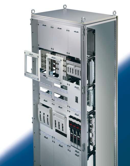
187 ISV ISV installation distribution enclosure
188 Installation distribution enclosure ISV-TS 8 enclosures B1 B approx Top view with side panels shown (B4). Width measurements Model No. B1 B2 B3 B4 B5 B6 B7 B8 B9 SV B B7 B8 B7 B9 B3 B2 B4 Planning the enclosures Order list of pre-configured enclosures including system accessories. Refer to the table for scope of supply. 1 Roof 2 Rear panel 3 Mounting angles 4 Gland plates, three-part 5 Contact hazard protection frame 6 Door Width in mm Packs of Height in mm Depth in mm Model No. SV Doors Approx. weight (kg) Base/plinth Components Height 100 mm TS 1 set front and rear Height 200 mm TS 1 set Trim panels (sides) Height 100 mm TS 1 set Height 200 mm TS 1 set Accessories Cable clamp rails PS Cable entry plates 1) TS TS side panels TS ) Cable entry grommets see Cat. 30, page 892 Lock systems see Cat. 30, pages Plastic cable gland plates see Cat. 30, page 896 Other sizes and designs available on request Doors with viewing window available on request Supply includes Material Sheet steel Surface finish Enclosure frame 1.5 mm Dipcoat primed in RAL 7044 Door(s) 2.0 mm Dipcoat primed in RAL 7044 Roof 1.5 mm Powder coated in textured RAL 7032 Rear panel 1.5 mm on the outside Three-piece gland plates 1.5 mm Zinc-plated Contact hazard protection frame in hard PVC, RAL 9002 Lock: Standard double-bit lock insert 188

189 ISV Technical specifications Rated current up to 400 A 630 A Rated surge current resistance I pk at a maximum busbar support centre distance of 300 mm 30 ka 45 ka Rated insulation voltage U i to VDE V AC cos phi 0.3 Cross-section of phase conductor L1 L3 30 x 5 mm 30 x 10 mm Cross-section of neutral conductor N 25 x 10 mm 25 x 10 mm Cross-section of PE conductor 12 x 10 mm 12 x 10 mm Protective measures Protection category 1 (with PE conductor) Overvoltage category 3 IP protection category IP 20 without door, IP 40/IP 55 with door Cable clamp rails These ensure strain relief for cable entry. Cable entry plates For simple, fast cable entry and sealing. Note: Climate control variants, see Cat 30, from page 446. Rittal enclosures are optionally available in RAL Cable entry grommets (up to 47 mm diameter) in conjunction with the cable entry plates: Fast and sealed! ISV installation distribution enclosure 189
190 Installation distribution enclosure Installation modules Contact hazard protection modules For covering open installation areas Cover is prepared for a lead seal Insulating material RAL 9002 Mechanical component installation Empty module 1) 1 WU =^ 250 mm 2) 1 U =^ 150 mm Size Packs of Model No. SV Width unit (WU) 1) Height unit (U) 2) mm mm mm mm mm mm mm mm mm mm mm mm mm mm mm mm Accessories: Terminal block Cable clamp rails For installation into 250 mm wide contact hazard protection modules see page 201 For attaching cable clamps Mounting plate modules With mounting plate in 2 mm zinc-plated sheet steel Cover is prepared for a lead seal Insulating material RAL 9002 Maximum usable depth 142 mm Mechanical component installation Mounting plate (W x H) Size Packs of Model No. SV Width unit (WU) 1) Height unit (U) 2) 200 x 150 mm mm mm x 300 mm mm mm x 450 mm mm mm x 600 mm mm mm x 150 mm mm mm x 300 mm mm mm x 450 mm mm mm x 600 mm mm mm ) 1 WU =^ 250 mm 2) 1 U =^ 150 mm 600 Available space in 1 =Mounting plate module 2 =Mounting plate module with deep cover 3 =Contact hazard protection module 4 =Contact hazard protection module with deep cover 190
191 ISV Support rail modules For installing terminal blocks, cable ties, etc. Top hat rail 35/15 mm to EN Slides in the 25 mm grid Cover is prepared for a lead seal Insulating material RAL Mechanical component installation Number of support rails 1 Size Packs of Model No. SV Width unit (WU) 1) Height unit (U) 2) mm mm mm mm mm mm mm mm mm mm mm mm mm mm mm mm ) 1 WU =^ 250 mm 2) 1 U =^ 150 mm 129 Accessories: 600 Terminal block Spacer Support rails Cable clamp rails For installation into 250 mm wide support rail modules For attaching to support rails For devices or terminals with snap fastening For attaching cable clamps see page 201 Support rail modules Mechanical component installation Mounting surface area W x H 190 x 210 mm, usable depth adjustable from mm Mounting surface area W x H 190 x 210 mm, usable depth adjustable from mm 1) 1 WU =^ 250 mm 2) 1 U =^ 150 mm Width unit (WU) 1) Variably usable with switchgear One-piece assembly block Cover is prepared for a lead seal Insulating material RAL 9002 Size Height unit (U) 2) Packs of Model No. SV mm mm mm mm ISV installation distribution 191
192 Installation distribution enclosure Installation modules Connection modules Mechanical component installation Terminal connection top and bottom 250 A, 4-pole 250 A, 5-pole 400 A, 4-pole 400 A, 5-pole 630 A, 4-pole 630 A, 5-pole 1) 1 WU =^ 250 mm 2) 1 U =^ 150 mm Round conductor: 1 x mm 2 or 2 x mm 2 Laminated flat copper: clamping area W x H 17 x 21 mm Round conductor: 1 x mm 2 or 2 x mm 2 Laminated flat copper: clamping area W x H 25 x 21 mm Round conductor: 1 x mm 2 or 2 x mm 2 Laminated flat copper: clamping area W x H 41 x 21 mm Width unit (WU) 1) For connecting copper and aluminium conductors Single-wire and multi-wire conductors with compressed wire end ferrule or laminated copper bar Rittal Flexibar S Cover is prepared for a lead seal Insulating material RAL 9002 Size Height unit (U) 2) Packs of Model No. SV mm mm mm mm mm mm mm mm mm mm mm mm Accessories: Laminated copper For connecting to the terminal block see page 105 bars of the connection module Cable clamp rails For attaching cable clamps see page
193 ISV Serial installation device modules For adding serial installation devices Top hat rail 35/15 mm to EN Cover is prepared for a lead seal Insulating material RAL Mechanical component installation 12 divider units (1 x 12 x 18 mm) 24 divider units (2 x 12 x 18 mm) 36 divider units (3 x 12 x 18 mm) 48 divider units (4 x 12 x 18 mm) 24 divider units (2 x 12 x 18 mm) 48 divider units (4 x 12 x 18 mm) 72 divider units (6 x 12 x 18 mm) 1) 1 WU =^ 250 mm 2) 1 U =^ 150 mm Width unit (WU) 1) Size Height unit (U) 2) Packs of Model No. SV mm mm mm mm mm mm mm mm mm mm mm mm mm mm Accessories: 600 Cover strips For blanking unneeded device cutouts see page 200 Terminal block For installation into 250 mm wide serial installation device modules see page BE 2 BE 4 HE 3 HE 2 HE 1 HE HE = U BE = WU ISV installation distribution enclosure 193
194 Installation distribution enclosure Installation modules NH on-load isolator modules Mechanical component installation Assembly block 1 x size 00 perforated and 160 A positioned as well 2 x size 00 as cutout in plate for 160 A NH on-load isolator 1 x size A Not included in the supply: NH on-load isolator* 1) 1 WU =^ 250 mm 2) 1 U =^ 150 mm 1 x size A 1 x size A Suitable for accommodating the Rittal on-load isolator sizes 00 to 3 for mounting plate installation Cover is prepared for a lead seal Insulating material RAL 9002 Width unit (WU) 1) Size Height unit (U) 2) Packs of Model No. SV mm mm mm mm mm mm mm mm mm mm * NH on-load isolator for mounting plate installation Size Model No. SV see page 1 Size Size Size Size
 1 WU")
195 ISV Power circuit-breaker modules Suitable for accommodating standard power circuit-breakers from ABB, Merlin Gerin, Moeller and Siemens in 3-pin configuration, up to 630 A Cover is prepared for a lead seal Insulating material RAL 9002 Mechanical component installation Mounting plate perforated and positioned for power circuit-breaker Not included in the supply: power circuit-breaker* 1) 1 WU =^ 250 mm 2) 1 U =^ 150 mm Width unit (WU) 1) Size Height unit (U) 2) Packs of Model No. SV mm mm mm mm mm mm mm mm mm mm mm mm * Power circuit-breaker I N Make ABB Merlin Gerin Moeller Siemens 160 A 1 Compact Tmax T1 Sentron VL160 NS NZM 7 3 Compact Tmax T2 Sentron VL160X NS A 2 Tmax T3 4 Compact NS NZM 7 4 Sentron VL A 5 SACE Isomax S5 6 Compact NS NZM 10 5 Sentron VL A 5 SACE Isomax S5 Compact 6 SACE Isomax S6 NS NZM 10 5 Sentron VL630 Note: The pitch patterns for attaching the power circuit-breakers and the accompanying cutout dimensions are shown in the ISV assembly instructions that are included with the ISV-TS 8 enclosures (see page 188/189). ISV installation distribution enclosure 195

196 Installation distribution enclosure Installation modules Busbar support 5-pole busbar support (60 mm bar centre distance) Suitable for configuring busbar connections, bus-mounting fuse bases, and NH bus-mounting on-load isolators size 00 Busbar connections in accordance with assembly instructions Cover is prepared for a lead seal Insulating material RAL 9002 Mechanical component installation 4 busbar supports for max. 2 height units 1) and max. 2 width units 2) Not included in the supply: Busbars 1) 1 U =^ 150 mm 2) 1 WU =^ 250 mm Usable busbar dimensions E-Cu Busbars L1/L2/L3 30 x 5 mm (400 A) 30 x 10 mm (630 A) Busbar N 25 x 10 mm Busbar PE 12 x 10 mm Packs of Model No. SV Accessories: Busbars E-Cu see page 104 Laminated copper bars see page 105 Conductor connection clamps for busbar connections see page 48 Plate clamps for busbar connections see page 48 Busbar connector see page Note: Depending on the configuration and connection variant, the Cu busbars have to be cut to the required length, prior to installation in accordance with the assembly instructions which is included with the ISV-TS 8 enclosures (see page 188/189). 5-pole busbars configuration feasible only for configuring busbar connections 1 uand NH bus-mounting on-load isolators size With bus-mounting fuse bases 2 only 3-pole configuration (L1/L2/L3) feasible. In this case, N and PE must be configured using busbar support SV (see page 40) or busbar module 2-pole (Model No. SV or SV see page 199). For enclosure-to-enclosure busbar connections, the following busbar connectors should be used (see page 104): Busbars Model No. SV L1/L2/L N PE
 1 WU =^ 250 mm 2) 1 U =^ 150 mm * Conductor connection clamps, plate clamps (see page 48) 2 Contact hazard protection cover for bus-mounting fuse bases Size Packs Description of For")
197 ISV Also required: 1 Contact hazard protection cover, one-piece Description Size Packs Model No. Width unit Height unit of SV (WU) 1) (U) 2) For busbar connections* mm mm ) 1 WU =^ 250 mm 2) 1 U =^ 150 mm * Conductor connection clamps, plate clamps (see page 48) 2 Contact hazard protection cover for bus-mounting fuse bases Size Packs Description of For bus-mounting fuse bases 6 x D 02-E 18 For bus-mounting fuse bases* 4 x D II-E 27, 3 x D III-E 33 1) 1 WU =^ 250 mm 2) 1 U =^ 150 mm Width unit (WU) 1) Height unit (U) 2) Model No. SV mm mm mm mm * Bus-mounting fuse bases and accessories (see page 62) Type Model No. Bus-mounting Contact hazard fuse base protection cover End caps D 02-E 18 SV D II-E 27 SV D III-E 33 SV Contact hazard protection covers for NH bus-mounting on-load isolator size 00 Description For NH bus-mounting on-load isolator* 1) 1 WU =^ 250 mm 2) 1 U =^ 150 mm Size Packs of Model No. SV Width unit (BE) 1) Height unit (U) 2) 1 x size mm mm x size mm mm * NH bus-mounting on-load isolator Size Model No. SV see page Size 00 66/ ISV installation distribution enclosure 197
 1) Size Height unit (U) 2) Packs of Model No.")
198 Installation distribution enclosure Installation modules NH fused isolators modules With busbars E-Cu (100 mm bar centre distance) For NH fused isolators size 00 or busbar connections Cover is prepared for a lead seal Insulating material RAL 9002 Configuration variants 1 2 Mechanical component installation Width unit (WU) 1) Size Height unit (U) 2) Packs of Model No. SV Cu busbar system: 3-pole, 630 A, mm mm with busbars 30 x 10 mm Not included in the supply: NH fused isolators* mm mm ) 1 WU =^ 250 mm 2) 1 U =^ 150 mm * NH fused isolator size 00 Cable outlet top/bottom, M8 connector (Model No. SV ) see page 90 Accessories: Conductor connection clamps for busbar connections see page 48 Plate clamps for busbar connections see page 48 Laminated copper bars see page 105 Note: In order to be able to ensure trouble-free cable connection, a contact hazard protection module (Model No. SV see page 190) has to be installed below the NH fused isolator modules. Busbar connection in accordance with ISV assembly instructions. 1 Contact hazard protection covers for NH fused isolator size 00 Size Packs Model No. Description Width unit Height unit of SV (WU) 1) (U) 2) 2 x size mm mm For NH fused isolator 4 x size mm mm ) 1 WU =^ 250 mm 2) 1 U =^ 150 mm 198
 1 WU =^ 250 mm 2) 1 U =^ 150 mm * Conductor connection clamps, plate clamps (see page 48) Busbar modules, 2-pole Description Bus unit: 2-pole for N and PE with busbars 30 x 10 mm 1) 1 WU =^")
199 ISV Also required: 2 Contact hazard protection cover, one-piece Description Size Packs Model No. Width unit Height unit of SV (WU) 1) (U) 2) For busbar connections* mm mm ) 1 WU =^ 250 mm 2) 1 U =^ 150 mm * Conductor connection clamps, plate clamps (see page 48) Busbar modules, 2-pole Description Bus unit: 2-pole for N and PE with busbars 30 x 10 mm 1) 1 WU =^ 250 mm 2) 1 U =^ 150 mm For connecting N and PE Contact hazard protection cover included Cover is prepared for a lead seal Insulating material RAL 9002 Size Packs of Model No. SV Width unit (WU) 1) Height unit (U) 2) mm mm mm mm Accessories: Conductor connection clamps for busbar connections see page 48 Plate clamps for busbar connections see page 48 Laminated copper bars see page 105 ISV installation distribution enclosure 199

200 Installation distribution enclosure Accessories Deep cover For increasing the usable depth. For installation on one-piece contact hazard protection covers W x H x D 450 x 250 x 43 mm Insulating material RAL 7035 Packs of Model No. SV Cover strips For blanking unnecessary component cutouts in serial installation device modules, max. 12 divider units (12 x 18 mm), divisible every 9 mm. Packs of Model No. SV Cover panel For blanking unnecessary cutouts for bus-mounting fuse bases, 108 mm wide. Packs of Model No. SV Wiring brackets for installing C rails 30/15 mm TS punched sections with mounting flanges TS frame section Packs of Model No. SV
201 ISV Spacers For configuring support rails with attachment screws, 53 mm high. Packs of Model No. SV Terminal block For installation into 250 mm wide contact hazard protection modules and support rail modules. 2-pole for N and PE, each with 20 x 4 mm 2, 5 x 25 mm 2. Packs of Model No. SV Cable clamp rails For attaching cable clamps (see Cat. 30, page 898) in connection modules contact hazard protection modules support rail modules Required width units of the modules Packs of Model No. SV 1 WU (250 mm) WU (500 mm) Support rails For snap fastening components or terminals, 15 mm high. Required width units of the modules Packs of Model No. SV 1 WU (250 mm) WU (500 mm) ISV installation distribution enclosure 201

202 Installation distribution enclosure Accessories ISV Cable entry gland Including seal Protection category IP 55 Insulating material RAL 7032 Design Packs of Model No. SV 14 x M25/ x M25/32/40, 1 x M32/40/50, 2 x M40/50/ With sealing membranes 32 x dia mm, 4 x dia mm, 3 x dia mm With entry glands up to 66 mm diameter Ø R Cutout dimensions for SV to SV
Rittal RiLine60. The fascinating 60 mm system of the future assembly-friendly, time-saving, individual and modular. including.
 Rittal RiLine60 including innovations 2007 The fascinating 60 system of the future assembly-friendly, time-saving, individual and modular R Rittal RiLine60 perfection in a 60 system Time-saving assembly,
NEW. Rittal RiLine60 UL 508. The fascinating 60 mm system of the future
 NEW Rittal RiLine60 UL 508 The fascinating 60 mm system of the future R Rittal RiLine60 UL 508 Perfection in a 60 mm system Time-saving assembly, versatile applications and individual modularity are the
RiLine mm system technology for the global market
 60 system technology for the global market 02 RiLine60 Busbar systems 3 and 4 pole Support + bars + contact hazard protection Flat copper bar system, see 276 in HB 33 PLS busbar system, see 278 in HB 33
Perfection in Technology Packaging
 Rittal Product Overview 2006 Perfection in Technology Packaging R We look to the future Rittal is already working enthusiastically on the solutions of the future. This is our tradition, and is the key
Technical System Catalogue Ri4Power
 Technical System Catalogue Ri4Power Order information Catalogue 33, from page 327 Ri4Power Form 1-4 Ri4Power Form 1-4 An individual system for the configuration of tested low-voltage switchgear with inner
Technical System Catalogue RiLine
 Technical System Catalogue RiLine Busbar systems Rittal offers a comprehensive system package with components for individual customer solutions. Wherever in the world they are used, Rittal busbar systems
System Benefits Should you have any further questions, please contact our UL hotline at: +49 (0)9563/ Connection Technology EQUES Technology
9563/ Connection Technology EQUES Technology") System Benefits The small external dimensions of the 60mm busbar system allow for a wide range of busbars, so that it can be easily adapted to a wide range of currents. These features result in the particularly
System Benefits The small external dimensions of the 60mm busbar system allow for a wide range of busbars, so that it can be easily adapted to a wide range of currents. These features result in the particularly
Rittal Product Overview 2008
 Rittal Product Overview 2008 Global = Faster, better, more efficient. R 2 Scaling new heights together We believe that close collaboration with our customers is a key source of Power for the future. Our
MANUAL 2018 AL 2018 U AN M
 MANUAL 2018 DEVELOPED IN RÖDENTAL, SUCCESSFUL WORLDWIDE Wöhner develops system solutions for the electro-technical market. For over 88 years, the Wöhner name has been synonymous with impressive technical
60mm-System classic 630A (800A) / 2500A
 / 2500A") 60mm-System classic 630A (800A) / 500A System Benefits The small external dimensions of the 60mm busbar system allow for a wide range of busbars, so that it can be easily adapted to a wide range of currents.
60mm-System classic 630A (800A) / 500A System Benefits The small external dimensions of the 60mm busbar system allow for a wide range of busbars, so that it can be easily adapted to a wide range of currents.
3NP1 Fuse Switch Disconnectors up to 630 A
 Switch Disconnectors 3NP1 Fuse Switch Disconnectors up to 630 A Introduction Overview All key product features at a glance available for all sizes Connection of circular conductors and laminated conductors
CRITO Connection technology. Double and triple T and TCC section busbars
 Centre feed unit 5 Centre feed unit Centre feed unit 5 Centre feed unit up to 4000 A combines the advantages of high short-circuit capacity, drill-free mounting, brace terminal technology and clearly structured
INNOVATION IS OUR POWER.
 MANUAL 2019 EN INNOVATION IS OUR POWER. Wöhner develops system solutions for the electro-technical market. For over 90 years, the Wöhner name has been synonymous with impressive technical achievements
Power distribution. RiLine fuse elements. NH fuse-switch disconnectors, size 000. For mounting plate assembly
 NH fuse-switch disconnectors, size 000 Version -pole, cable outlet at the top/bottom For the use of fuse inserts to EN 60 - Technical specifications to IEC/EN 60 947-, see chapter -5, page 6 see chapter
30Compact 200 A / 360 A
 200 A / 360 A 2 BUSBAR SYSTEM TECHNOLOGY 200 A / 360 A 2 Compact busbar system for control systems and power distribution up to 360 A The busbar system is the ideal solution for distribution boards with
8WH2 Spring-Loaded Terminals
 8WH2 Spring-Loaded Terminals /2 Introduction /3 General data on 8WH /7 8WH through-type terminals 1) /18 8WH hybrid through-type terminals 1) /21 8WH fuse terminals /23 8WH isolating blade terminals /25
8WH2 Spring-Loaded Terminals
 8WH2 Spring-Loaded Terminals /2 Introduction /3 General data on 8WH /7 8WH through-type terminals 1) /18 8WH hybrid through-type terminals 1) /21 8WH fuse terminals /23 8WH isolating blade terminals /25
Busbar Systems CHAPTER11
 763.422.22 763.422.2600 CHAPTER 38 SUBJECT TO CHANGE WITHOUT NOTICE EQUIPMENT PROTECTION Chapter Contents 60-mm Busbar System Overview...40 60-mm System Classic MCCB Mounting Reference....41 Support Spacing
PANEL PANEL MOUNTING COMPONENTS
 PANEL PANEL MOUNTING COMPONENTS For conventional wiring, Wöhner offers a comprehensive range of panel components for fastening to a DIN rail or mounting plate. The fuses and associated connection technology
Rittal CM Compact System Enclosures
 Rittal CM Compact System Enclosures Compact class = Top class: Infinite possibilities R Compact enclosure on the outside, Top enclosure on the inside! Index Convincing details... 3 5 Compact system enclosures
BETA Switching Switches and Light Indicators
 Siemens AG 2008 BETA Switching /2 Product overview /3 5TE8 control switches / 5TE4 pushbuttons /2 5TE5 light indicators /5 5TE8 ON/OFF switches /22 5TE9 busbars /24 5TE switch disconnectors Siemens ET
vertical fuse switch disconnectors
 SWITCHGEAR ARS vertical fuse switch disconnectors - touch protection IP 30 from the front - fibre glass extra strenghtened, self extinguishing thermoplastics - double clearance between open contacts -
Type Pack size Weight Part no. kg/100 units for undrilled busbars 30, 40, 50, 60 x 10. Dimensions Current Pack size Weight Part no.
 1 01 628 01 617 01 79 01 25 Universal busbar support 100mm, 3-pole Type Pack size Weight Part no. for undrilled busbars 30, 0, 50, 60 x 10 7.1 01 79 06 End cover for busbar support 01 79 10 5.3 01 25 06
General notes. Operating conditions
 1 General notes Wöhner busbar systems and components are the result of expert development based on many years of experience. They have been exhaustively tested and hold many approvals. The correct selection
Power distribution. General remarks
 When developing the Rittal busbar systems and their components, Rittal drew on the latest state of the art and the currently valid standards and regulations. These applications are used by specialist companies
Horizontal fuse disconnects
 THE NAME FOR SAFETY Horizontal fuse disconnects Horizontal fuse disconnects Horizontal fuse Disconnects are used in building installations, switchgear and controlgear as well as in power utility networks.
The Complete Range. Drawing of the NH Fuse-Switch, 3-pole switching, horizontal design for busbar supply on a 60 mm busbar systems
 The Complete Range Easy mounting onto supporting rails Protection against accidental contact in the standart version Perforated versions for connections Drawing of the NH Fuse-Switch, 3-pole switching,
SENTRON Switching and Protection Devices Switch Disconnectors
 SENTRON Switching and Protection Devices Switch Disconnectors /2 Introduction 3K, 3KE, 3LD Switch Disconnectors 3K, 3KE Switch Disconnectors up to 1000 /4 General data /8 Floor mounting 3LD Main and EMERGENCY-STOP
Viking 3 - Screw connection Disconnect terminal blocks
 87045 LIMOGES Cedex Telephone: (+33) 05 55 06 87 87 - Fax: (+33) 05 55 06 88 88 Viking 3 - Screw connection 1. General features... 1 2. Range...2 3. Standards... 2 4. Technical features... 3 5. Dimensions...
CENTRE FEED UNIT UP TO 4000A. Safety
 CENTRE FEED UNIT UP TO 000A Safety Centre feed unit New TCC section busbar: Connection options with CRITO PowerClip and CRITO ProfiClip, and terminal studs (screw in c-slot). 1-pole, side busbar support
IEC Low Voltage General Purpose Protection
 , 6A, 0/400VAC (/440VAC) Complying with DIN VDE 0660 Part 07 EN / IEC 60947- DIN VDE 066 Part IEC 6069- DIN VDE 068 DIN VDE 4880 The D0-LINOCUR is a combination of switch-disconnector-fuse and NEOZED 6
e n e r g i a HULANICKI BEDNAREK sp. z o.o. HABeR-M Switchgear system rated up to 1600A 1
 e n e r g i a HULANICKI BEDNAREK sp. z o.o. Switchgear system rated up to 1600A www.haberenergia.pl 1 Switchgear system rated up to 1600 A Low voltage switchgear system utilising moulded-case circuit-breakers
185mm-System power 2500A. Expertise
 185mm-System power 2500A Expertise System advantages The 185mm-System power is designed for use in efficient power distribution assemblies with a high short-circuit withstand capacity. The narrow design
3/2 Introduction. Unequipped Distribution Boards (Flat Pack) 3/6 8GK1 surface-mounting distribution boards
 3/6 8GK1 surface-mounting distribution boards") ALPHA 400 - DIN Wall-Mounted Distribution Boards /2 Introduction Unequipped Distribution Boards (Flat Pack) /6 8GK1 surface-mounting distribution boards Pre-Assembled Unequipped Distribution Boards /7
ALPHA 400 - DIN Wall-Mounted Distribution Boards /2 Introduction Unequipped Distribution Boards (Flat Pack) /6 8GK1 surface-mounting distribution boards Pre-Assembled Unequipped Distribution Boards /7
TeSys GV2 - GV3 Manual Starters and Protectors
 TeSys GV GV Manual Starters and Protectors A stronger, longterm connection Courtesy of Steven Engineering, Inc. 0 Ryan Way, South San Francisco, CA 94080670 General Inquiries: (800) 67048 www.stevenengineering.com
Index. Manual Motor Starters 1. Auxiliary Contact Blocks 1. Trip Alarm Auxiliary 1. Switch. Shunt Release 1. Under-voltage Release 2.
 Index Index Page Manual Motor Starters 1 Auxiliary Contact Blocks 1 Trip Alarm Auxiliary 1 Switch Shunt Release 1 Under-voltage Release 2 Accessories 2 Busbar Connectors 2 Enclosures 2 Leistung, kw C mv
Electronic Circuit Breaker ESS20-0..
 Electronic Circuit Breaker ES-0.. Description Electronic circuit breaker type ES-0.. is designed to ensure selective disconnection of individual loads in systems which are powered by a DC 4 V switch-mode
Terminal Blocks Product Catalog Terminal Block Supplement. Introduction. 8WH6 ipo Plug-In Terminals. 8WH6 ipo Installation Terminals
 Terminal Blocks 2013 Product Catalog Terminal Block Supplement Introduction 8WH6 ipo Plug-In Terminals 8WH6 ipo Installation Terminals 8WH2 Spring-Loaded Terminals 1 2 3 4 8WH 8WH5 Combination Plug-In
Siemens AG Switch Disconnectors SENTRON. Configuration. Edition 10/2015. Manual. siemens.com/lowvoltage
 SENTRON Configuration Manual Edition 10/2015 siemens.com/lowvoltage 2 Introduction LD main control and EMERGENCY-STOP switches up to 250 A 4 Introduction 7 Front mounting 10 Floor mounting 11 Distribution
Distribution Blocks & Bus-bar Solutions
 Distribution Blocks & Bus-bar Solutions Insulated Multi Laminate Flexible Copper Bus-bars Threaded Copper Bus-bars Solid Copper Bus-bars Bus-bar Insulators & Supports Insulated Flexible Copper Braided
Flexible. Intelligent. Trendsetting.
 www.eaton.com www.moeller.net Flexible. Intelligent. Trendsetting. The easy way to connect. Product Information Motor-protective circuit-breaker PKE with electronic wide-range overload protection. Obliged
IN STAINLESS STEEL: Compact enclosures Enclosures and support arm systems for the human/machine interface Large enclosures
 IN STAINLESS STEEL: Compact enclosures Enclosures and support arm systems for the human/machine interface Large enclosures R RITTAL SYSTEM PARTNERS Perfect holistic solutions Be it automation, communications
 Approvals (p. 906) 0 371 61 0 371 63 0 371 64 0 371 66 0 371 69 0 371 68 0 371 00 0 371 08 0 371 20 Connecting (p. 300) 1 connection - 1 entry/1 outlet ELECTRICAL FUNCTION TERMINAL BLOCKS INSULATION EQUIPOTENTIAL
LED system light Sensationally bright
 LED system light Sensationally bright 2 Rittal LED system light LED system light Perfect enclosure illumination The most innovative lighting technology, tailored to Rittal enclosures. Do not settle for
MULTIBLOC 2.RST8 Size 2, 400A, 690VAC, Design for bus bar installation, Triple Pole
 MULTIBLOC 2.RST8 IEC FUSE SWITCH DISCONNECTORS NH FUSE SWITCH DISCONNECTOR The production programme of MULTIBLOC 2.RST8 comprises NH fuse switch disconnectors for 400A. Products are designed in triple
Product Data For FARNELL
 ae Product Data For FARNELL ae Uniset is / Varioset is ae EL ELECTRONIC KOMBI SYSTEM WALL MOUNTING Pole clamp For reliable, convenient fastening to round or square poles. For pole diameter/size:
DOUBLE-LEVEL TERMINAL BLOCKS SRKD SSLD
 DOUBLE-LEVEL TERMINAL BLOCKS SRKD SSLD PRODUCT INFORMATION Double-level terminal blocks SRKD SSLD CONTA-CLIP offers an innovative line of double-level feed-through terminals SRKD and protective-earth terminals
SAK A real classic that became synonymous with connection technology
 SAK A real classic that became synonymous with technology Or Once upon a time there was a company called Weidmüller that created the best terminals in the world using plastic and metal. Weidmüller has
MULTIBLOC 1.RST8 Size 1, 250A, 690VAC, Design for bus bar installation, Triple Pole
 MULTIBLOC 1.RST8 IEC FUSE SWITCH DISCONNECTORS NH FUSE SWITCH DISCONNECTOR The production programme of MULTIBLOC 1.RST8 comprises NH fuse switch disconnectors for 250A. Products are designed in triple
8WH6 ipo Installation Terminals
 /2 Introduction /4 8WH through-type terminals /6 8WH through-type screw terminals /8 8WH N-conductor isolating terminals /10 8WH N-conductor isolating screw terminals /12 8WH installation terminals More
Fuse switch disconnectors
 SWITCHGEAR 62 RBK pro Fuse switch disconnectors designed for distribution of electricity and protection of electrical equipment against short-circuits and overloads with industrial fuse links. ENERGY SAFELY
PANEL-MOUNTING COMPONENTS FUSE HOLDERS. Quality
 PANEL-MOUNTING COMPONENTS FUSE HOLDERS Quality For conventional wiring, Wöhner offers a comprehensive range of panel components for fastening to a DIN rail or mounting plate. The fuses and associated
KAM A Lighting Busbar System KAP A Plug-in Busbar Distribution System
 25-32 A Lighting Busbar System 4-63 A Plug-in Busbar Distribution System / CONTENTS E-LINE / General 2-3 System 4 Technical Characteristics 5 Standard Busbars 6 Standard Elements 7 Tap Off Plugs 8 Standard
IVS Distribution System. IVS - Table of Contents
 IVS - Table of Contents Overview System characteristics IVS System description Sheet steel wall-mounted DB for residential & functional buildings - IP30 Sheet steel wall-mounted DB for industrial applications
SENTRON 3NP1 Fuse Switch Disconnectors up to 630 A
 Introduction Overview All key product features at a glance available for all sizes Connection of circular conductors and laminated conductors Fuse monitoring possible throughout Busbar supports can be
MULTIBLOC 3.ST8 Size 3, 630A, 690VAC, Design for Bottom Fitting, 3-,4-pole
 MULTIBLOC 3.ST8 IEC FUSE SWITCH DISCONNECTORS NH FUSE SWITCH DISCONNECTOR The production programme of MULTIBLOC series 3.ST8 comprises NH fuse switch disconnectors for 630A. They are designed for bottom
Empty enclosures IEC 62208
 374 www.hensel-electric.de/en in accordance with for customized solutions and individual applications for example for low-voltage switchgear and controlgear assemblies i n accordance with the IEC 61439-series
Current transformers. Current transformers
 Current transformers Current transformers Moulded case current transformer Moulded case CT, class 1 and 0.5 / 5 A Increased reliability Both halves of the housing overlap rather than butting up against
CONTA-CONNECT SUPPLEMENTS
 CONTA-CONNECT SUPPLEMENTS CONTA-CONNECT system HSKG High-power stud terminals HSKG The newest generation of stud terminals from CONTA-CLIP offers secure connections for all energy-transmitting applications.
System pro M compact Miniature Circuit Breaker SU200M for branch circuit protection acc. to UL 489
 System pro M compact Miniature Circuit Breaker SU200M for branch circuit protection acc. to UL 489 2CDC021004S0014 2CDC021046S0014 The miniature circuit breaker SU 200 M is ABB s solution for UL 489 branch
SION vacuum circuit-breaker.
 A perfect fit for every substation: vacuum circuit-breaker. The new line in medium voltage. Power Transmission and Distribution Every innovation begins with an idea. Form, functionality and flexibility
INDUSTRIAL COMPONENTS CATALOGUE. Terminals, switches and fuse bases
 INDUSTRIAL COMPONENTS CATALOGUE Terminals, switches and fuse bases 2 Ensto at your service Ensto is an international industrial group and a family business specialising in the development, manufacture
XL 3 -N SimPly, EfficiEnt And SAfE. 3 - PHASE distribution boards up to 250 A
 XL 3 -N 125 250 SimPly, EfficiEnt And SAfE 3 - PHASE distribution boards up to 250 A the global specialist in ElEctricAl And digital building infrastructures Xl 3 -n Comprehensive and reliable range for
Internationally approved.
 E X - M A N U A L M O T O R S T A R T E R S Up to 2 A Motors have to be protected against over loads, phase failures and overheating: CEAG s power circuit breaker and manual motor starter features phase-failure
XL Distribution enclosures WORKSHOP SPECIFICATIONS
 800 Distribution enclosures WORKSHOP SPECIFICATIONS With its extensive ranges, the Legrand offer meets your quality standards and provides real freedom and simplicity of installation together with acknowledged
THE NEW TS IT RACK 8
 THE NEW TS IT RACK 8 Fast and reliable Fast Loosen the 48. (9 ) quickrelease fastener, slide into the correct position, and latch Reliable Maximum load capacity up to,000 N Convenience in perfection Interior
Selection Guide Motor Control Device Solutions
 Selection Guide Motor Control Device Solutions Expect more and get it from c3controls. Our portfolio of Motor Control Devices consists of worldclass products designed and manufactured to meet your requirements
It s as simple as A,B,C...
 TE 7000 It s as simple as A,B,C... Designing a data centre should be made easy and configuring a rack should be easier. In fact it should be as simple as ABC... This quick find brochure is designed to
Mechanical engineering partner
 Mechanical engineering partner Reliable technology that improves productivity The main thing is that everything works well! In mechanical and electrical engineering everything has to work smoothly, be
MULTIBLOC 1.ST8 Size 1, 250A, 690VAC, Design for Bottom Fitting, 1-,2-,3-,4-pole
 MULTIBLOC 1.ST8 IEC FUSE SWITCH DISCONNECTORS NH FUSE SWITCH DISCONNECTOR The production programme of MULTIBLOC series 1.ST8 comprises NH fuse switch disconnectors for 250A. They are designed for bottom
D509E. Manual Motor - Starters
 D509E Manual Motor - Starters Index Page Manual Motors Starters 182 Auxilliary Contact Blocks 182 Trip Alarm Aux. Switch 182 Shunt Release 182 Under-voltage Release 183 Accessories 183 Busbar Connectors
Industrial Control Transformers
 6 Industrial Control Transformers Section 6 Industrial Control Transformers provide a low and safe control voltage for the operation of electromagnetic devices, such as motor starters, contactors, solenoids
Safety Switches with Separate Actuator SKC
 Safety Switches with Separate Actuator SKC In terms of lengths, the SKC safety position switch is the 15 mm shorter variant of the SK. This makes it the right choice for confined installation conditions.
FUSERBLOC Fuse combination switches with rear connection for industrial fuses up to 400 A
 Fuse protection fuser_737_a_1_cat.eps fuser_738_a_1_cat.eps The solution for > Motor load break > Protection of industrial processes FUSERBLOC REAR / FRONT connections 3 x 250 A fuser_739_a_1_cat.eps Strong
USA Canada On the Internet: Toll Free wieland Product Range Electrical Connections
 0.2 F 01/02 270 Excerpt from our master catalogue wiecon PCB terminals In Ageneral, all Wieland components which are obliged to have the identification are provided with the A mark Pluggable PCB terminals
INNOZED D0 fuse-bases with touch protection
 INNOZED D0 fusebases with touch protection INNOZED D0 fusebases with touch protection FUSE HOLDERS, FUSE BASES AND SUPPORTS IEC D0 & D FUSE BASES FEATURES & BENEFITS INNOZED is a fuse base for D0 fuselinks,
Application guide. Tmax Link OEM UL 891 Switchboard Program
 Application guide Tmax Link OEM UL 891 Switchboard Program 04 Tmax Link Overview 04 Standards 04 UL File Extension Process Overview 05 Electrical Data 05 Technical Data 05 Ambient Conditions 08 Circuit
ATyS S - ATyS d S Remotely operated Transfer Switching Equipment from 40 to 125 A
 Transfer switches The solution for > Genset < 90 kva > Heating systems > Climate control > Ventilation systems > Telecommunications atys-s_018_a Strong points Function products are 4 pole remotely operated
ICT TRANSFORMERS. Industrial Control Transformers provide a low and safe control voltage for the operation of many electromagnetic devices
 ICT TRANSFORMERS Industrial Control Transformers provide a low and safe control voltage for the operation of many electromagnetic devices TA SERIES INDUSTRIAL CONTROL TRANSFORMER Industrial control transformers
FUSE-LINKS FOR PHOTOVOLTAIC APPLICATIONS
 1 2 06 PML 10/14x85 1500V FUSE HOLDERS 08 CLIP CONTACT FOR φ10 FUSE LINKS 05 PMX & 14x51 FUSE HOLDERS 02 gpv & 14x51 600 &/1100 FUSE LINKS 03 gpv 1200 & 1500V FUSE LINKS 04 gpv NH1, NH2 & NH3 FUSE LINKS
Outdoor system solutions
 Outdoor system solutions 2 The whole is more than the sum of its parts The same is true of Rittal The System. With this in mind, we have bundled our innovative enclosure, power distribution, climate control
Miniature Circuit-Breakers (MCBs)
") Product Overview Miniature Circuit-Breakers (MCBs) Design Tripping characteristics Rated current I n Rated breaking capacity Power supply company product range 5SP3 E 16 - A Standard product range 5SQ2
Product Overview Miniature Circuit-Breakers (MCBs) Design Tripping characteristics Rated current I n Rated breaking capacity Power supply company product range 5SP3 E 16 - A Standard product range 5SQ2
FUSERBLOC Fuse combination switches for industrial fuses up to 1250 A
 Fuse protection fuser_548_a cat The solution for > Motor load break. > Protection of industrial cabinet. FUSERBLOC 6 to 25 A Strong points fuser_52_a cat Function FUSERBLOC 2 to 4 A FUSERBLOC are manually
INNOZED D0 fuse-bases with touch protection
 D0 fusebases with touch protection D0 fusebases with touch protection FUSE HOLDERS, FUSE BASES AND SUPPORTS IEC D0 & D FUSE BASES FEATURES & BENEFITS is a fuse base for D0 fuselinks, sizes D0 and D02.
CrossBoard. The new basic system
 CrossBoard The new basic system THE REVOLUTION HAS A NAME: CrossBoard The name CrossBoard stands for the future in control panel manufacture and describes the standard interface for the new modular power
Fuse switch disconnectors
 SWITCHGEAR RBK Fuse switch disconnectors intended for distribution of electricity and protection of electrical equipment against short-circuits and overloads, with industrial fuse links ENERGY SAFELY SWITCHED
Residual Current Protective Devices / Arc Fault Detection Devices (AFDDs)
") Introduction Overview Devices Page Application Standards Used in / Personnel, material and fire protection, as well as protection against direct contact. SIGRES with active condensation protection for
Introduction Overview Devices Page Application Standards Used in / Personnel, material and fire protection, as well as protection against direct contact. SIGRES with active condensation protection for
WELCOME TO THE WORLD OF COMPLETE AUTOMATION. Innovative MCS Starter Solutions. MCS Starters and the New Mounting System 141A
 WELCOME TO THE WORLD OF COMPLETE AUTOMATION Innovative MCS Starter Solutions MCS Starters and the New Mounting System 141A Welcome to the Wide World of Allen-Bradley Starters Innovative solutions for state
MULTIVERT 250A Size 1, 690VAC
 MULTIVERT 250A IEC FUSE SWITCH DISCONNECTORS NH VERTICAL FUSE SWITCH DISCONNECTOR FEATURES & BENEFITS MULTIVERT NH vertical fuse switch disconnectors meet all functions of NH fuse switch disconnectors.
Molded-Plastic Distribution Systems
 Molded-Plastic Distribution Systems / Introduction ALPHA 8HP molded-plastic distribution systems /8 Empty enclosures / Modular installation devices /4 DIAZED/NEOZED fuse systems /7 NP fuse switch disconnectors
B kv Gas-insulated Substations
 72.5 145 kv Gas-insulated Substations The increasing demand for electrical power in cities and industrial centres requires the installation of a compact and efficient distribution and transmission network.
SHIELD-CONNECTION CLIPS SAB
 SHIELD-CONNECTION CLIPS SAB PRODUCT INFORMATION CONTA-ELECTRONICS Shield-connection clips SAB Overview of the product line Description of the SABK shield-connection bracket system 3 Shield-connection bracket
MS /27/2015. ABB contact for United States of America. General Information Extended Product Type: Categories
 Page 1 of 5 MS132-10 ABB contact for United States of America General Information Extended Product Type: Product ID: EAN: Catalog Description: Long Description: MS132-10 1SAM350000R1010 4013614400100 MS132-10
PHOENIX CONTACT
 Current transformers INTERFACE Data sheet 03359_en_03 PHOENIX CONTACT 20-04-04 Description The PACT Analog current transformers form a complete range of bus-bar, plug-in and winding current transformers
8WH6 ipo Plug-In Terminals
 / Introduction /3 /4 8WH6 through-type terminals /8 8WH6 fuse terminals /9 8WH6 isolating blade terminals /11 8WH6 isolating terminals /13 8WH6 two-tier terminals More technical product information: Service&Support
FUSERBLOC Fuse combination switches for industrial fuses up to 1250 A
 Fuse protection fuser_548_a_1_cat The solution for > Motor load break > Protection of industrial processes FUSERBLOC 63 to 125 A Strong points fuser_532_a_1_cat Function FUSERBLOC 32 to 4 A FUSERBLOC are
BSL Size 1 250A, Size 2 400A, Size 3 630A, 690VAC
 BSL Size 1 250A, Size 2 400A, Size 3 630A, 690VAC FUSE RAILS IEC NH FUSE RAILS FEATURES & BENEFITS Installation on to Dimensions of s and cable connections are equivalent to those of MULTIVERT APPLICATIONS
FUSERBLOC CD. The universal Fuse Combination Switch FROM 20 TO 1250 A. Industrial Switching & Protection Systems
 FUSERBLOC CD The universal Fuse Combination Switch FROM 20 TO 1250 A SOCOMEC GROUP SWITCHING PROTECTION & UPS Industrial Switching & Protection Systems SWITCHING FUSERBLOC CD THE UNIVERSAL FUSE COMBINATION
The Rittal Flex-Block base/plinth system
 The Rittal Flex-Block base/plinth system 50 Save time Fast assembly by simply clipping together the base/plinth components Easily bayed with toolless baying clip The enclosure is easily transported in
B kv T&D GAS INSULATED SWITCHGEAR
 GAS INSULATED SWITCHGEAR B 105 170 300 kv The increasing demand for electrical power in cities and industrial centers necessitates the installation of a compact and efficient distribution and transmission