Technical System Catalogue Ri4Power
|
|
|
- Barrie Hawkins
- 5 years ago
- Views:
Transcription

1 Technical System Catalogue Ri4Power

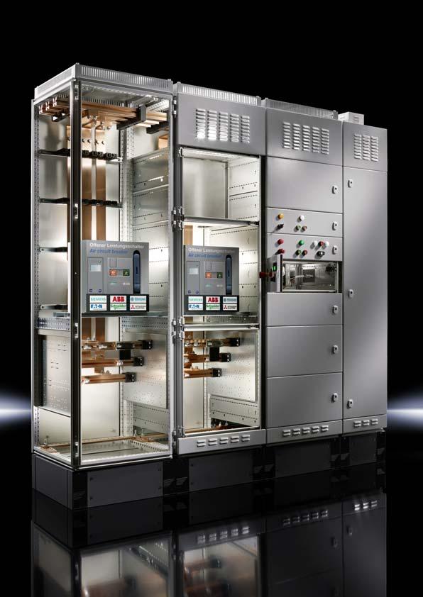
2 Order information Catalogue 33, from page 327 Ri4Power Form 1-4 Ri4Power Form 1-4 An individual system for the configuration of tested low-voltage switchgear with inner form separation. The flexible combination of Ri4Power field types supports optimum configuration for a wide range of applications. Ri4Power Form 1-4 offers a very high level of operator protection. Thanks to extensive busbar insulation and subdivision of the compartments, the occurrence and spread of accidental arcs is largely prevented. Tested safety Design verification to the internationally valid standard IEC Tests with ASTA certification Protection category up to IP 54 Tested accidental arcing protection to IEC Additional preventative accidental arcing protection A list of planning instruction contents may be found on page


3 Form 1-4 Modular system For low-voltage switchgear with design verification to IEC/EN /-2. For control systems and power distribution. Structured system solution for switchgear with Form separation 1-4b. Simple, installation-friendly system assembly. Busbar systems up to 5500 A RiLine60 The compact busbar system up to 1600 A. Maxi-PLS The assembly-friendly system. Flat-PLS The flat bar system for high power requirements. Tested PE conductor system. High levels of short-circuit resistance up to 100 ka for 1 sec./220 ka. Modular enclosure system Based on enclosure platform TS 8. Flexible, modular front design. Roof plates to suit every requirement. Modular compartment configuration for internal compartmentalisation up to Form 4b. Internal cover plates, contact hazard protection for circuit-breaker and NH fuse-switch disconnector sections. Accessories for Ri4Power. Simple planning Power Engineering Software SV Configuration of low-voltage switchgear with design verification. Simple, fast assembly with automatically generated assembly plan. Generation of parts lists with graphical output. 2-2

4 Form 1-4 Universal design at its best Order information Catalogue 33, from page 327 Benefits at a glance: Exceptional flexibility with the selection of modules and fields Simple, safe, tried-and-tested assembly High quality solution offering excellent value for money Fast, reliable system planning with the Rittal Power Engineering software Thanks to the large number of different modules and fields plus form separation 1-4, Ri4Power offers the right solution for every application. Be it in the process industry, industrial plant, energy generation or infrastructure, the Ri4Power system solution is at home in every environment. Process industry Sewage treatment plants Heavy industry (mining, iron, steel) Cement works Waste disposal industry Paper industry Chemicals, petrochemicals Pharmaceutical industry Industrial plants Automotive industry Mechanical engineering Shipbuilding, marine engineering Energy generation Small power plants Wind and solar power Biomass power plants Buildings, infrastructure Schools Banks Insurance companies Data centres Football stadiums Hospitals Festival halls and exhibition buildings Airports 2-3


5 Form Circuit-breaker section For switchgear from all well-known manufacturers such as Siemens, ABB, Mitsubishi, Eaton, Terasaki, Schneider Electric and General Electric. Use of air and moulded case circuit-breakers. 2 Coupling section Combination of a circuit-breaker section with a spacesaving, side busbar riser. Reliable separation into individual busbar sections to boost equipment availability. 3 Outgoing section Flexible design of the interior installation. Fully insulated distribution busbars with extensive connection system. For compact circuit-breaker and motor starter combinations. 4 Cable chamber Available from a field width of 300 mm. Optional cable entry from above or below. Flexible installation with Rittal system accessories. Highest design concordance 4b thanks to optimum terminal compartments. 5 Fuse-switch disconnector section For switchgear from Jean Müller, ABB, Siemens. Alternatively also suitable for installation of equipment modules from Jean Müller. 2-4
6 Circuit-breaker section Order information Catalogue 33, from page 327 Benefits at a glance: Consistently modular layout. Fast, time-saving assembly technique. To fit circuit-breakers from well-known manufacturers including ABB, Eaton, General Electric, Mitsubishi, Schneider Electric, Siemens and Terasaki The circuit-breaker section is used as the power infeed to switchgear and to output large currents from the switchgear. Busbar systems up to 5500 A with Maxi-PLS or Flat-PLS are dimensioned and individually configured according to requirements. The integrated modular concept and high manufacturing quality ensure fast, time-saving configuration. The Ri4Power Form1-4 system technology is designed to fit air circuit-breakers from all well-known manufacturers. Finally, the compartment divider is assembled, ensuring optimum access to all connection points throughout the entire assembly process. 2-5


7 Circuit-breaker section Terminal space Stepped, assembly-friendly arrangement of the connection bars. Cable connection system for optimum connection of all conductor types. Flexible positioning of the bars in the connection space, thanks to the modular side panel system Circuit-breaker Circuit-breakers available as fixed or rack-mounted, allowing free choice of positioning. Complete, matching connection system for air circuitbreakers (ACB) from all well-known manufacturers. Modular configuration of the compartments, for circuitbreakers and function groups, in accordance with your requirements Busbar system Maxi-PLS up to 4000 A, alternatively Flat-PLS up to 5500 A. Main busbar system 3- or 4-pole. Busbar positioning optionally in the roof, bottom or upper or lower rear section. Section to section connection system for all busbar systems, with no drilling required

8 System example of a circuit-breaker section Overview of components Enclosure Enclosure system accessories The components required for an air circuit-breaker section are comprised of the enclosure, the enclosure system accessories, the compartment and the busbar systems. 2 3 Rittal Power Engineering The software Rittal Power Engineering is highly recommended for easy, fast configuration of section types and systems. This continuously updated, graphics oriented software tool supports customer-specific configuration and automatically produces bills of materials, CAD drawings and order lists of equipment and panels. The export interfaces mean that data and drawings are easily transmitted to other programs such as Word or Excel, or to Eplan Electric P8. Compartment configuration Busbar systems

9 System example of a circuit-breaker section Bill of materials Enclosure Qty. 1) Packs of Model No. 1 TS 8 modular enclosure, W/H/D: 800 x 2200 x 800 mm Enclosure system accessories 2 Base/plinth components, front and rear, 200 mm high Base/plinth trim, side, 200 mm high Front trim panel kit, IP 2X, W/H: 800 x 300/100 mm Horizontal roof frame bar, W: 800 mm Cross member for compartment divider, W: 800 mm Solid roof plate, W/D: 800 x 800 mm Partial door, W/H: 800 x 600 mm Lock with double-bit insert Configuration parameters: Enclosure dimensions W x H x D: 800 x 2200 x 800 mm, with base/plinth 200 mm Roof plate IP 54 Front trim panel IP 2X Form 4b Busbar system, top Maxi-PLS 3200, 4-pole, in roof area, without cover PE busbar design 80 x 10 mm For air circuit-breaker (ACB) Mitsubishi AE, 3200 A, 4-pole, rack-mounted system, positioned behind the door, with cable connection system Maxi-PLS 3200 A, 4-pole Compartment divider, vented Compartment configuration 10 Compartment side panel module, H/D: 600 x 800 mm Compartment side panel module, H/D: 150 x 800 mm Compartment side panel module connection space, H/D: 450 x 800 mm Mounting bracket for compartment divider for enclosure depth 800 mm Mounting bracket for ACB + compartment divider for enclosure depth 800 mm Air circuit-breaker support rail Form 2-4 for enclosure width 800 mm Attachment set for air circuit-breaker Compartment divider for busbar system gland, vented, W/D: 800 x 800 mm Gland plate for compartment divider, W: 800 mm Partial mounting plate, W/H: 800 x 600 mm Stacking insulator Support rail for stacking insulator for enclosure width 800 mm Busbar systems 20 Busbar support Maxi-PLS End support Maxi-PLS System attachment, Maxi-PLS 3200, 4-pole, in roof area Busbars Maxi-PLS 3200, 691 mm Busbars Maxi-PLS 3200, 799 mm Connection bracket for Maxi-PLS 3200, 3-pole, 3 x 100 x 10 mm, for D: 800 mm Connection bracket for Maxi-PLS 3200, for N, 3 x 100 x 10 mm, for D: 800 mm U contact makers Maxi-PLS 3200, W: 100 mm Sliding blocks Maxi-PLS 3200, M Connection kit, top, for ACB, design code 828F8J1H8H6F Connection kit, bottom, for ACB, design code 828F8J1H8H6F Screw connection for connection bracket Busbars 80 x 10 mm, 792 mm PE/PEN combination angles, flat, 40 x 10 mm ) Required quantity. 2-8
10 Coupling section Order information Catalogue 33, from page 327 Benefits at a glance: Reliable separation of the busbar sections thanks to extensive, stable compartmentalisation Total failures are prevented in the event of a malfunction Option of reducing the requirements of overall short-circuit resistance Reliable disconnecting and connecting of the main busbar systems in low-voltage switchgear is the task of a coupling section. For systems with several infeeds, this prevents total failure and helps to reduce costs in the event of a malfunction. (Similarly, the requirements governing overall shortcircuit resistance may be reduced). Overall, investment, operating and servicing costs are reduced with rising levels of reliability, since in the event of servicing, individual busbar sections may be de-energised without having to switch off the entire system. The coupling section is a combination of a circuit-breaker section with a busbar riser optionally arranged on the left or right. The large number of identical parts and work stages therefore also translates into convincing cost and time benefits during assembly. 2-9

.")

11 Coupling section Coupling switch 1 Complete, matching connection system for air circuitbreakers (ACB) from all well-known manufacturers. 2 The same system architecture as the circuit-breaker section reduces the number of different items and the required assembly work. 2 3 Standardised system accessories facilitate fast population. 1 3 Busbar riser Version with Maxi-PLS or alternatively Flat-PLS. Space-saving, modular and flexible arrangement of the busbar riser (on the left, right, or both sides). Solid compartmentalisation provides a high level of safety for humans and equipment. 4 5 Busbar configuration 7 Main busbar routing in the rear panel area. Alternatively, other positions are also supported Option of using the other compartments separately. Flexible design with standard items e.g. for controlling and monitoring the coupling switch. 9 Individual selection of the roof plate and front trim panel allows process-optimised population of the switchgear

12 System example of a coupling section Overview of components Enclosure Enclosure system accessories The components required for a coupling section are comprised of the enclosure, the enclosure system accessories, the compartment and the busbar systems. 3 4 Rittal Power Engineering The Rittal Power Engineering software is highly recommended for easy, fast configuration of section types and systems. This continuously updated, graphics oriented software tool supports customer-specific configuration and automatically produces bills of materials, CAD drawings and order lists of equipment and panels. The export interfaces mean that data and drawings are easily transmitted to other programs such as Word or Excel, or to Eplan Electric P8. Compartment configuration Busbar systems
13 System example of a coupling section Bill of materials Enclosure Qty. 1) Packs of Model No. 1 TS 8 modular enclosure, W/H/D: 800 x 2200 x 800 mm TS 8 busbar enclosure, W/H/D: 200 x 2200 x 800 mm Enclosure system accessories 3 Base/plinth components, front and rear, 200 mm high Base/plinth trim, side, 200 mm high Front trim panel kit, IP 2X, W/H: 800 x 100 mm Cross member for compartment divider, W: 800 mm Roof plate, vented, IP 2X, W/D: 800 x 800 mm Partial door, W/H: 800 x 200 mm Partial door, W/H: 800 x 300 mm Partial door, W/H: 800 x 600 mm Lock with double-bit insert Baying connectors, external Angular baying bracket TS/TS Configuration parameters: Enclosure dimensions W x H x D: 800 x 2200 x 800 mm, 200 x 2200 x 800 mm, with base/plinth 200 mm Roof plate IP 2X vented Front trim panel IP 2X vented Form 4b Busbar system, top Maxi-PLS 2000, 4-pole, in rear area, without cover PE busbar design 80 x 10 mm For air circuit-breakers (ACB) ABB, E2, 2500 A, static installation, 4-pole, positioned behind the door Busbar system, bottom Maxi-PLS 2000, 4-pole, directly underneath the circuit-breaker Compartment divider, vented Compartment configuration Punched section with mounting flange for coupling section, for enclosure 10 width 800 mm TS punched section with mounting flange, 23 x 73 mm, for enclosure width 800 mm Compartment side panel module, H/D: 200 x 800 mm Compartment side panel module, H/D: 600 x 800 mm Compartment side panel module, H/D: 300 x 800 mm Compartment side panel module, H/D: 200 x 600 mm Compartment side panel module, H/D: 300 x 600 mm Mounting bracket for compartment divider for enclosure depth 800 mm Mounting bracket for compartment divider for enclosure depth 600 mm Mounting bracket for ACB + compartment divider for enclosure depth 800 mm Air circuit-breaker support rail Form 2-4 for enclosure width 800 mm Attachment set for air circuit-breaker Compartment divider, vented, W/D: 800 x 600 mm Compartment divider for busbar system gland, vented, W/D: 800 x 800 mm Gland plate for compartment divider, W: 800 mm Partial mounting plate, W/H: 800 x 200 mm Partial mounting plate, W/H: 800 x 300 mm Stacking insulator Support rail for stacking insulator for enclosure width 800 mm Mini-TS profile, 17 x 15.5 mm, L: mm Mini-TS profile, 17 x 15.5 mm, L: mm Frame connector piece for Mini-TS profile Corner connector for Mini-TS profile Coupling set mounting kit for enclosure depth 800 mm ) Required quantity. 2-12
14 System example of a coupling section Bill of materials Configuration parameters: Enclosure dimensions W x H x D: 800 x 2200 x 800 mm, 200 x 2200 x 800 mm, with base/plinth 200 mm Roof plate IP 2X vented Front trim panel IP 2X vented Form 4b Busbar system, top Maxi-PLS 2000, 4-pole, in rear area, without cover PE busbar design 80 x 10 mm For air circuit-breakers (ACB) ABB, E2, 2500 A, static installation, 4-pole, positioned behind the door Busbar system, bottom Maxi-PLS 2000, 4-pole, directly underneath the circuit-breaker Compartment divider, vented Busbar systems Qty. 1) Packs of Model No. Busbar support Maxi-PLS Busbar support Maxi-PLS 2000, suitable for top-mounting End support Maxi-PLS System attachment Maxi-PLS 2000/4, rear section, frame chassis System attachment Maxi-PLS 2000/4, in the roof area System attachment Maxi-PLS 2000/4, coupling section Busbars Maxi-PLS 2000, 725 mm Busbars Maxi-PLS 2000, 799 mm Busbars Maxi-PLS 2000, special length 1299 mm Busbars Maxi-PLS 2000, special length 1399 mm Busbars Maxi-PLS 2000, special length 1499 mm Busbars Maxi-PLS 2000, special length 1599 mm Connection bracket for Maxi-PLS 1600/2000, 3-pole, 2 x 100 x 10 mm Connection bracket for Maxi-PLS 1600/2000, for N, 2 x 100 x 10 mm Connection kit, top, for ACB, design code 828D9A2G4H6D Connection kit, bottom, for ACB, design code 828D9A2G4H6D Terminal studs for connector kit Screw connection for connection bracket U contact makers Maxi-PLS 2000, W: 100 mm Corner bracket Maxi-PLS Sliding blocks Maxi-PLS 2000, M Connection kit Maxi-PLS 2000/3, coupling set in the rear section Connection kit Maxi-PLS 2000/N, coupling set in the rear section Busbars 80 x 10 mm, 992 mm PE/PEN combination angles, flat, 40 x 10 mm ) Required quantity. 2-13
15 2-14
16 Outgoing section Order information Catalogue 33, from page 327 Benefits at a glance: For use with control units and power distribution Individual, targeted configuration of the compartments Simple, secure connection of the distribution bar system to the main bar system Flexible planning, simple adaptation, fast assembly and a high level of security are convincing features Installation of switchgear, power supply outlets or controllers the application areas of the outgoing section are very versatile. With multifunctional components, the individual compartments may be quickly assembled and configured to suit your requirements. The busbar distribution system may be positioned adjacent to, behind or directly in the compartments and is easily and safely connected to the main busbar systems using system components. The benefits are impressive, both during assembly and subsequent operation: simple assembly, flexible adaptation and a high level of security. 2-15


17 Outgoing section Distribution busbars 1 RiLine60 is ideal for small rated currents. Alternatively, for higher currents, Maxi-PLS or Flat-PLS may be used for the main busbar. 2 Simple insulation and cover with standard parts. 3 T-connection kits for connecting main and distribution busbar systems Compartments with power outlet 5 4 Interior installation is individual, flexible and tailored to your requirements. 5 Arrangement of the distribution busbar in the indoor busbar system, alternatively: Behind the compartments/partial mounting plates At the side adjacent to the modular outgoing section to the side infeed into the compartments RiLine60 circuit-breaker adaptor for time-saving, maintenance-friendly installation of circuit-breakers up to 630 A. 8 Compartments with control units Use of control units to suit individual requirements. For all well-known brands of switchgear and control devices from Siemens, ABB, Mitsubishi, Eaton, Schneider Electric, General Electric and Terasaki. Space-optimised configuration thanks to graduation of the compartment heights. Rittal system accessories offer comprehensive configuration options and numerous design variants depending on the intended application

18 System example of an outgoing section Overview of components Enclosure Enclosure system accessories The components required for an outgoing section are comprised of the enclosure, the enclosure system accessories, the compartment and the busbar systems Rittal Power Engineering The software Rittal Power Engineering is highly recommended for easy, fast configuration of section types and systems. This continuously updated, graphics oriented software tool supports customer-specific configuration and automatically produces bills of materials, CAD drawings and order lists of equipment and panels. The export interfaces mean that data and drawings are easily transmitted to other programs such as Word or Excel, or to Eplan Electric P8. Compartment configuration Busbar systems
19 System example of an outgoing section Bill of materials Enclosure Qty. 1) Packs of Model No. 1 TS 8 modular enclosure, W/H/D: 600 x 2200 x 600 mm Enclosure system accessories 2 Base/plinth components, front and rear, 200 mm high Base/plinth trim, side, 200 mm high Front trim panel kit IP 54, W/H: 600 x 100 mm Cross member for compartment divider, W: 600 mm Solid roof plate, W/D: 600 x 600 mm Partial door, W/H: 600 x 150 mm Partial door, W/H: 600 x 300 mm Partial door, W/H: 600 x 400 mm Partial door, W/H: 600 x 600 mm Partial door, W/H: 600 x 250 mm Lock with double-bit insert Configuration parameters: Enclosure dimensions W x H x D: 600 x 2200 x 600 mm, with base/plinth 200 mm Roof plate IP 54, solid Front trim panel IP 54, solid Form 4a Main busbar system RiLine60, PLS 1600, 4-pole, in rear section, top, with busbar cover PE busbar design 30 x 10 mm Distribution busbar system RiLine60, PLS 1600, 4-pole, in compartment (indoor), with cover Compartment divider for RiLine60, solid Device-specific design of the compartments and adaptors Compartment configuration 9 Compartment side panel module, H/D: 100 x 425 mm Compartment side panel module, H/D: 200 x 425 mm Compartment side panel module, H/D: 150 x 425 mm Compartment side panel module, H/D: 100 x 600 mm Compartment side panel module, H/D: 600 x 600 mm Compartment side panel module, H/D: 150 x 600 mm Compartment side panel module, H/D: 300 x 600 mm Compartment side panel module, H/D: 400 x 600 mm Gland plate for compartment side panel modules Mounting bracket for compartment divider for enclosure depth 425 mm Mounting bracket for compartment divider for enclosure depth 600 mm Compartment divider for RiLine60, W/D: 600 x 401 mm Partial mounting plate, W/H: 600 x 150 mm Partial mounting plate, W/H: 600 x 300 mm Partial mounting plate, W/H: 600 x 400 mm Partial mounting plate, W/H: 600 x 600 mm Partial mounting plate, W/H: 600 x 250 mm Support frame for DIN rail-mounted devices, W: 600 mm, 2-row Mini-TS profile, 17 x 15.5 mm, L: 62.5 mm Mini-TS profile, 17 x 15.5 mm, L: mm Frame connector piece for Mini-TS profile Corner connector for Mini-TS profile Busbar systems RiLine60 busbar support PLS 1600 PLUS RiLine60 end cover for PLS 1600 PLUS Busbar PLS 1600 A, 495 mm long RiLine60 base tray for PLS 1600 PLUS RiLine60 cover section, L: 1100 mm RiLine60 support panel Circuit-breaker component adaptor 160 A, 690 V, outlet at bottom, 3-pole Circuit-breaker component adaptor 160 A, 690 V, outlet at bottom, 4-pole Circuit-breaker component adaptor 250 A, 690 V, outlet at bottom, 4-pole Circuit-breaker component adaptor 630 A, 690 V, outlet at bottom, 3-pole Insert strip, W: 25 mm, for SV / Busbar, 30 x 10 mm, for enclosure width 600 mm PE/PEN combination angles, 30 x 10 mm System attachment for RiLine60 for enclosure width 600 mm T-connector RiLine60, 1600 A, 4-pole, indoor, PLS Distribution busbar PLS 1600, indoor, for enclosure height 2200 mm ) Required quantity. 2-18

20 Cable chamber Order information Catalogue 33, from page 327 Benefits at a glance: Versatile range of system accessories for optimum cable routing Cable entry optionally from below, from above, or from below and above Choice of various different cable entry glands Finger-proof construction The distribution of cables into and out of the individual compartments is the task of the cable chamber. Depending on the main busbar system chosen, cable entry may be either from below, above, or below and above. Choose from a range of cable entry glands for the roof plate. The main busbar system is covered in a contact hazard-proof way, depending on the type and configuration. Ri4Power offers every conceivable option for designing PE and N distribution busbars. In each case, the panel builder s requirements are effectively met to perfection. 2-19


21 Cable chamber TS 8 cable chamber enclosure 1 Roof plate for cable gland plates, cable entry glands. 2 3 Covering of the main busbar system. Mini-TS sections as an auxiliary construction. 1 4 Main busbar system with RiLine60, alternatively with Maxi-PLS or Flat-PLS PE and N distribution busbars Busbar supports for PE and N distribution busbars. Distribution busbar to match the enclosure heights. Supporting structure of Mini-TS sections for individual attachment PE/PEN, cable entry, base/plinth 8 PE/PEN busbar tailored to the enclosure width. Configurable in various cross-sections PE/PEN combination angles for attaching the PE busbar and incorporating the TS 8 enclosure into the protective measure C rails for cable attachment, alternatively cable clamp rail from the mounting angle. Gland plates divided in the depth Base/plinth components, front and rear plus base/plinth trim, side
22 System example of a cable chamber Overview of components Enclosure Enclosure system accessories The components required for a cable chamber are comprised of the enclosure, the enclosure system accessories, the compartment and the busbar systems. 2 3 Rittal Power Engineering The Rittal Power Engineering software is highly recommended for easy, fast configuration of section types and systems. This continuously updated, graphics oriented software tool supports customer-specific configuration and automatically produces bills of materials, CAD drawings and order lists of equipment and panels. The export interfaces mean that data and drawings are easily transmitted to other programs such as Word or Excel, or to Eplan Electric P8. Compartment configuration Busbar systems

23 System example of a cable chamber Bill of materials Enclosure Qty. 1) Packs of Model No. 1 TS 8 cable chamber enclosure, W/H/D: 400 x 2200 x 600 mm Enclosure system accessories 2 Base/plinth components, front and rear, 200 mm high Base/plinth trim, side, 200 mm high Roof plate for cable gland plates, W/D: 400 x 600 mm ISV cable entry gland, M25/32/40/50/ ISV cable entry gland, with entry fittings ISV cable entry gland, solid Support rails for TS 8, W/D: 600 mm Configuration parameters: Enclosure dimensions W x H x D: 400 x 2200 x 600 mm, with base/plinth 200 mm Roof plate for cable gland plates Form 4a Main busbar system RiLine60, PLS 1600, 4-pole, in rear section, top, with busbar cover PE busbar design 30 x 10 mm PE/N distribution busbar version PE + N PE 30 x 10 mm N 30 x 10 mm Cable clamp rail C rail Compartment configuration 9 Cover plate for main busbar system, W: 400 mm Mini-TS profile, 17 x 15.5 mm, L: 62.5 mm Mini-TS profile, 17 x 15.5 mm, L: mm Mini-TS profile, 17 x 15.5 mm, L: mm Mini-TS profile, 17 x 15.5 mm, L: mm Mini-TS profile, 17 x 15.5 mm, L: mm Frame connector piece for Mini-TS profile Corner connector for Mini-TS profile T-connector piece for Mini-TS profile Busbar systems RiLine60 busbar support PLS 1600 PLUS RiLine60 end cover for PLS 1600 PLUS Busbar PLS 1600 A, 495 mm long RiLine60 base tray for PLS 1600 PLUS RiLine60 cover section, L: 1100 mm RiLine60 support panel Busbar, 30 x 10 mm, for enclosure width 400 mm PE/PEN combination angles, 30 x 10 mm System attachment for RiLine60 for enclosure width 400 mm Distribution busbar 30 x 10 mm, indoor, for enclosure height 2000 mm Busbar support N/PE, 2-pole ) Required quantity. 2-22
24 Fuse-switch disconnector section Order information Catalogue 33, from page 327 Benefits at a glance: Compact, variable distribution of power specifically for fused switchgear Suitable for switchgear enclosure technology Short-circuit-rating to 100 ka, also for the distribution busbar system Internal separation according to customer requirements, from Form 1 to 4b The compact, variable distribution of electrical power with fused switchgear can be achieved with a fuse-switch disconnector section. The modular Ri4Power configuration system allows you to fully prepare for the installation of NH slimline fuseswitch disconnectors sizes 00 to 3 from Jean Müller or ABB/Siemens. With device modules from Jean Müller, live-interchangeable control units may also be integrated into the fuse-switch disconnector section. The distribution busbars are selectively and economically dimensioned according to requirements. The main and the distribution busbar system can be configured for shortcircuit rating of up to 100 ka. Internal sub-division in the fuse-switch disconnector section is from Form 1 to Form 4b, depending on customer requirements, thanks to the optional selection of components. 2-23


25 Fuse-switch disconnector section Busbar system Accommodates standard commercially available flat copper bars from 50 x 10 to 100 x 10 mm for rated currents up to 2100 A. Connection of the distribution busbars with terminal block, no drilling required. Flexible busbar support arrangement on a 25 mm pitch pattern for optimum fuse-switch disconnector configuration Switchgear area Individual interior configuration for: 4 a) Jean Müller Sasil fuse-switch disconnectors, Jean Müller device modules 5 b) ABB SlimLine fuse-switch disconnectors/ Siemens 3NJ62 fuse-switch disconnectors 6 Variable positioning of ventilation trim panels between the fuse-switch disconnector according to manufacturer s instructions Cable connection space Upgradable to Form 4b with device-specific terminal covers. Application-specific design of PE and N for the distribution busbar system. Optional contact hazard protection even without form separation

26 System example of a fuse-switch disconnector section Overview of components Enclosure Enclosure system accessories The components required for a fuseswitch disconnector section are comprised of the enclosure, the enclosure system accessories, the compartment and the busbar systems Rittal Power Engineering The Rittal Power Engineering software is highly recommended for easy, fast configuration of section types and systems. This continuously updated, graphics oriented software tool supports customer-specific configuration and automatically produces bills of materials, CAD drawings and order lists of equipment and panels. The export interfaces mean that data and drawings are easily transmitted to other programs such as Word or Excel, or to Eplan Electric P8. Compartment configuration Busbar systems

27 System example of a fuse-switch disconnector section Bill of materials Enclosure Qty. 1) Packs of Model No. 1 TS 8 fuse-switch disconnector enclosure, W/H/D: 1200 x 2200 x 800 mm Enclosure system accessories 2 Base/plinth components, front and rear, 200 mm high Base/plinth trim, side, 200 mm high Front trim panels, fuse-switch disconnector section, top 350 mm/bottom 150 mm Assembly kit for fuse-switch disconnector section JM, H: 2200 mm Maxi-PLS roof plate, vented, W/D: 1200 x 800 mm, 50 mm high, RAL Baying connector, external Angular baying bracket TS/TS Support rails for TS 8, W/D: 800 mm Configuration parameters: Enclosure dimensions W x H x D: 1200 x 2200 x 800 mm, with base/plinth 200 mm Roof plate IP 2X vented Front trim panel IP 2X vented Form 4b Busbar system, top Flat-PLS 100, 4-pole, 4 x 100 x 10 mm, reinforced, in roof section with cover PE busbar design 80 x 10 mm For Jean Müller (JM) NH slimline fuse-switch disconnectors, type Sasil Compartment configuration 8 Divider panel, fuse-switch disconnector section JM/ABB, H/D: 2200 x 800 mm Dividing plate for fuse-switch disconnector section section for JM Contact hazard protection, fuse-switch disconnector section, W/D: 1200 x 800 mm Compartment side panel module, H/D: 200 x 800 mm Compartment side panel module, H/D: 600 x 800 mm Busbar systems 12 Busbar support Flat-PLS 100 suitable for stabiliser bar System attachment for busbar support Flat-PLS 100, in roof/bases, 3-/4-pole, D: 800 mm Busbar stabiliser bar, 4-pole Busbars E-Cu, 100 x 10 x 2400 mm Busbar claws up to 4 x 100 x 10 mm, 1-pole Screw connections M10 x Contact piece for Flat-PLS, 4 bars, W: 60 mm Connection bracket, fuse-switch disconnector section, Flat-PLS 100, L1 3, D: 800 mm Connection bracket, fuse-switch disconnector section, Flat-PLS 100, N, D: 800 mm End support for fuse-switch disconnector section, 3-/4-pole, bar width: 100 mm Busbar support for fuse-switch disconnector section, 3-/4-pole, bar width: 100 mm Cover for distribution busbar, fuse-switch disconnector section JM, enclosure height: 2000/2200 mm Punched rail for attaching the distribution busbar cover of the JM fuse-switch disconnector section, enclosure height: 2000/2200 mm Distribution busbar for fuse-switch disconnector section, W/H: 100/2200 mm Terminal block, distribution busbar for fuse-switch disconnector section, 80/100 mm Busbar support up to 1600 A, 3-pole, 185 mm bar centre distance for busbars E-Cu 50 x 10 to 80 x 10 mm Distribution busbar for fuse-switch disconnector section, W/H: 80/2000 mm Busbars, 1192 x 80 x 10 mm, for enclosure width 1200 mm PE/PEN combination angles, flat, E-Cu 40 x 10 mm ) Required quantity. 2-26
28 List of contents Planning instructions Application Definitions and basic principles Rated voltage U n Rated operating voltage U e Rated insulation voltage U i Rated surge voltage resistance U imp Rated current of switchgear assemblies I na Rated current of circuits I nc Rated diversity factor RDF Rated peak withstand current I pk Rated short-time withstand current I cw Conditional rated short-circuit current I cc Rated frequency f n Pollution degree Material group Conditions of installation of assemblies Stationary/movable installation of the low-voltage switchgear Protection category Use by skilled persons or ordinary persons Classification according to electromagnetic compatibility (EMC) Special operating conditions External design Protection from mechanical impact Type of layout Forms of power supply net TN, IT, TT Selection and dimensioning of the main busbar system Parameters for selection of the main busbar system Rated peak withstand current I pk and rated short-time withstand current I cw Installation instructions Design of the busbar systems with regard to infeed and rated current I na and rated short-circuit withstand capability I cw Short-circuit current distribution with various infeed variants (disregarding impedance) Rated current of switchgear assemblies I na Rated current of the busbar system I nc Description of switchgear section types Air circuit-breaker sections Coupling switch section Modular outgoing feeder section Fuse-switch disconnector section with vertical distribution busbar system for horizontally arranged NH slimline fuse-switch disconnectors and device modules Fuse-switch disconnector section with Rittal NH slimline fuse-switch disconnectors Cable chamber Corner section Distribution busbar section Busbar riser General remarks and recommendations...59 Making busbar connections and connections to copper busbars...59 Choice of internal connections...59 Air circuit-breakers (ACB)...59 Moulded-case circuit-breakers (MCCB)...59 NH fuse-switch disconnectors...60 Motor-starter combinations (MSC)...60 General wiring...60 Operation and maintenance...61 Notes on the use of aluminium cables...61 List of design verifications to be obtained...61 Switchgear installation types...62 Conductor cross-section in relation to short-circuit withstand capacity (unprotected active conductors)...62 Cable routing or cable entry...62 Neutral conductors Requirements...63 Notes on the positioning and design of N, PE and PEN conductors...64 Dimensioning of the PE with the aid of calculation I 2 txsec. Appendix B (normative)...65 Transport units and weights...66 Accidental arcing protection for human safety...67 System overview of the standard main busbar routing in Form (1) Short-circuit rating diagram for busbar supports RiLine60, Flat-PLS 60/100 and Maxi-PLS Admissible heat losses within compartments...70 Busbar temperature increase and heat loss...70 Explanation of TSK versus design verification...70 The central earth point (CEP) in TN-S supply net...71 PE conductor connection and current carrying capacity of PE conductor connections within a Ri4Power switchgear...71 Internal separation of switchgear enclosures...72 Fuse designations, operating categories...73 Connection of busbars to DIN Protection categories IP...74 Project checklist for Rittal Ri4Power low-voltage switchgear and controlgear assemblies...75 Rated currents I nc ACB (air circuit-breakers)...77 Rated current I nc for moulded-case circuit-breakers MCCB...80 Rated busbar currents

29 List of contents Planning instructions Tables Table 1: Root-means-square value I cw of the short-circuit current Table 2: Determination of selection parameters pursuant to standard IEC/EN , Annex C Table 3: Rated current I nc of the distribution busbar system in modular outgoing feeder sections Table 4: Rated current I nc and short-circuit resistance I cw of the vertical distribution busbar in the NH slimline fuse-switch disconnector section Table 5: Rating data for NH slimline fuse-switch disconnectors from ABB/Jean Müller Table 6: Rated diversity factor RDF of NH slimline fuse-switch disconnectors from ABB/Jean Müller depending on the number of NH slimline fuse-switch disconnectors per section Table 7: Rating data for Rittal NH slimline fuse-switch disconnectors Table 8: Rated diversity factor RDF 1 for NH slimline fuse-switch disconnectors depending on the number per section Table 9: Rated diversity factor RDF 2 for NH slimline fuse-switch disconnectors depending on the enclosure protection category Table 10: Horizontal rails and contact makers for main busbar systems in the roof section Table 11: Selection of distribution busbar system in the distribution busbar section Table 12: Admissible rated current I nc and connection cross-section for NH fuse-switch disconnectors Table 13: Design verification in detail Table 14: Conductor selection and laying conditions (IEC , chapter 8.6.4) Table 15: Selection of PE/PEN conductors on the basis of rated short-term withstand current Table 16: Factor k depending on the conductor material and insulating material Table 17: Rated short-time withstand current I cw for SV /SV Table 18: Characteristic curve allocation for SV /SV Table 19: Heat loss table for compartment with distribution busbar Table 20: Forms of internal separation Table 21: Operating categories of fuse inserts...73 Table 22: Colour code for fuse inserts...73 Table 23: Positioning of the IP code...74 Table 24: Item 1, protection against contact and foreign bodies...74 Table 25: Item 2, level of protection against water...74 Table 26: Item 3 additional letter...74 Table 27: Levels of protection against access to hazardous live parts, code number Table 28: Levels of protection against solid bodies, code number Table 29: Rated currents I nc for air circuit-breakers ABB...77 Table 30: Rated currents I nc for air circuit-breakers Eaton...77 Table 31: Rated currents I nc for air circuit-breakers Mitsubishi...78 Table 32: Rated currents I nc for air circuit-breakers Schneider Electric...78 Table 33: Rated currents I nc for air circuit-breakers Siemens...79 Table 34: Rated currents I nc for air circuit-breakers Terasaki...79 Table 35: Rated currents I nc for moulded-case circuit-breakers ABB...80 Table 36: Rated current I nc for moulded-case circuit-breakers Eaton...82 Table 37: Rated current I nc for moulded-case circuit-breakers Mitsubishi...83 Table 38: Rated currents I nc for moulded-case circuit-breakers Schneider Electric...85 Table 39: Rated currents I nc for moulded-case circuit-breakers Siemens...86 Table 40: Rated currents I nc for moulded-case circuit-breakers Terasaki...87 Table 41: Rated busbar currents RiLine Table 42: Rated busbar currents Maxi-PLS...88 Table 43: Rated busbar currents Flat-PLS

30 Busbar system Maxi-PLS Order information Catalogue 33, from page 328 Benefits at a glance: High productivity, thanks to simple project planning and fast assembly of the system technology. Cable and busbar connections are achieved with the triedand-trusted sliding block technique, no drilling required. Compact busbar design. Standardised connection components throughout. High standard of safety. All you have to do is make your selection, plan and install! The innovative Maxi-PLS busbar system allows customeroriented configuration of Motor Control Centres and lowvoltage switchgear in building technology, industry and regenerative energy recovery. The standardised Maxi-PLS busbar systems feature an exceptionally compact design and ingeniously simple assembly technology. The Maxi-PLS system with stepped arrangement is particularly ideal for the connection of external cables. All system components are standardised, inexpensively mass-produced, and supplied ready for configuration. This makes Maxi-PLS the ideal link between the power supply and power distribution to the smallest piece of equipment. 2-29
.")


31 Busbar system Maxi-PLS Beneficial system technology Beneficial system technology and coordinated dimensional pitch patterns for precise-fit, fast installation of Maxi-PLS holders and bars. Compact design with square profile cross-section (45 x 45 mm to 2500 A, 60 x 60 mm to 4000 A). The section lengths are sized to match the enclosure widths. Individual contact hazard protection with simple clip-on mounting of covers. Four attachment levels The four attachment levels of Maxi-PLS busbars facilitate attachment and contacting on all sides with no drilling required. Contact makers facilitate the direct connection of intersecting bars. Simple, practical connection Linear contacting of cables, laminated flat copper, connection brackets and connection kits. Terminal studs and connection plates for ring terminals, as well as all variants of cables and flat bars. Stepped arrangement ensures simple, clear assembly of cables and laminated flat copper. 2-30

32 Busbar system Flat-PLS Order information Catalogue 33, from page 332 Benefits at a glance: Busbar system up to 5500 A/100 ka 1 sec. For standard commercially available flat copper bars. Extremely flexible and assembly-friendly. Short-circuit ratings is inexpensively enhanced. Effective contact hazard protection. High standard of safety. In order to meet global rising demands for energy, low-voltage switchgear needs to become ever more powerful and larger. These days, there are a growing number of installations with rated currents of 3200 to 4000 A or even higher. In order to meet these requirements, with Flat-PLS, Rittal offers a busbar system for rated currents of up to 5500 A load capacity. The Flat-PLS busbar system significantly broadens the tried-and-trusted modular range for switchgear manufacturers, and the Ri4Power is therefore available as a low-voltage switchgear system with design certificate up to 5500 A with commercially available flat copper bars. 2-31


33 Busbar system Flat-PLS Dimensioning in numerous variants Dimensioning of busbars in numerous variants with just two busbar support variants for bar formats ranging from 40 x 10 to 60 x 10, as well as 80 x 10 and 100 x 10 mm. Also suitable for aluminium and copper-plated aluminium bars. Every support can accommodate 2, 3 or 4 bars per phase. Optimum adaptation to the corresponding rated current. Very flexible and assembly-friendly, thanks to the 4-part support design. Connection with no drilling required Connection of Flat-PLS busbar systems with no drilling required, thanks to longitudinal connectors. Adapted to your requirements. Enhanced short-circuit ratings, thanks to 3-phase installation concept with busbar claws and stabiliser bars. All-round contact hazard protection All-round contact hazard protection thanks to a variable range of precise-fit cover sections and cover components for busbars and connection kits. Reduces the potential for accidents and accidental arcing. Significantly enhances the reliability of low-voltage switchgear. The optional busbar claws may also be integrated into contact hazard protection. 2-32
 and NH fuse-switch disconnectors (100 mm). Assembly on a mounting plate or mounting frame.")
34 Busbar systems (100/185/150 mm) Order information Catalogue 33, from page 340 Benefits at a glance: Tested busbar systems for use in power distribution. Suitable for the assembly of NH slimline fuse-switch disconnectors (100/185 mm) and NH fuse-switch disconnectors (100 mm). Assembly on a mounting plate or mounting frame. These systems are designed for mounting NH fuse-switch disconnectors and fuse-switch disconnectors, and for safe power transmission and distribution. 2-33

35 Busbar systems (100/185/150 mm) 1 Busbar system 100 mm bar centre distance The busbar support is designed to accommodate bars up to 60 x 10 mm Tested for applications with rated operating currents of up to 1250 A and max. 110 ka peak short-circuit current. The busbar system with 100 mm bar centre distance is used for mounting NH fuse-switch disconnectors, sizes 00, 1, 2 and 3, as well as NH slimline fuse-switch disconnectors, size 00. When using inserts, this can be reduced to 50 x 10 mm, 40 x 10 mm or 30 x 10 mm. 2 Busbar system 185 mm bar centre distance The busbar support is designed to accommodate bars up to 80 x 10 mm Tested for applications with rated operating currents of up to 1600 A and max. 155 ka peak short-circuit current. The busbar system with 185 mm bar centre distance is mainly used for mounting NH slimline fuse-switch disconnectors, sizes 00, 1, 2 and 3. Inserts enable this to be reduced to 60 x 10 mm or 50 x 10 mm. The special design of the busbar support facilitates seamless top mounting in the vicinity of the support. In addition, the individual modules of the busbar support can also be used as single-pole supports for PE, PEN or neutral conductor applications. 3 Busbar system 150 mm bar centre distance Multi-terminal busbar system for two conductors running parallel to one another. This facilitates the connection of cables, lines and laminated busbars using connection plates, with no drilling required. Tested for applications with rated operating currents of up to 3000 A and max. 155 ka peak short-circuit current. The busbar system is the simplest way of distributing high currents up to 3000 A over two parallel flat copper bars. Thanks to the 10 mm spacing pieces, flat copper bars 60 x 10 mm may alternatively be used. This system is used primarily in systems where no direct mounting of equipment or adaptors is required. Two support variants are available with 150 mm bar centre distance: 2 x 3-pole up to 2500 A 2 x 3-pole up to 3000 A 2-34

36 Connection system Order information Catalogue 33, from page 338 Benefits at a glance: Standardised system packages for leading manufacturers of air circuit-breakers. Simple, fast assembly with standard components and ready-to-install connection components. Compact, parallel bar arrangement, with positioning of the connections tailored to the respective air circuit-breaker. Standardised, tested connections High standard of safety. All you have to do is make your selection, plan and install! Ingeniously simple assembly of Motor Control Centres and switchgear in the heavy current range. The various Rittal components are supplied ready to configure. The same applies to the entire connection system. Complete system packages, customised for all leading manufacturers of air circuit-breakers, NH switchgear or other conductor versions, ensure optimum connection with standardised components. 2-35


37 Connection system Connector kits Connected to Maxi-PLS and Flat-PLS busbar systems using standardised components tailored to the respective air circuit-breaker. Standardised, tested connections ranging from the incoming cable connection of the switch panel, to the air-circuit-breaker connections, through to the main busbar. To fit all standard air circuit-breakers. Pre-assembled connection brackets, ready to install. Connection system All busbar systems have connection components that allow simple, secure connection for the respective conductor type. With contact makers or copper spacers, even solid copper bars are easily connected to the main busbars without conflict. When connecting to the Maxi-PLS busbar system, isolator chassis may optionally be used to increase the clearance and creepage distance. Design certificate/type-tested Type-tested to EN /IEC Design certificate to IEC Special testing under accidental arcing conditions to EN /IEC ASTA certificates. IEC IEC IEC IEC
38 Application This planning handbook should be used to create lowvoltage switchgear and controlgear assemblies with the Ri4Power modular system from Rittal, as the basis for planning and configuration. The explanations in this handbook apply to the creation of low-voltage switchgear and controlgear assemblies that must meet the requirements of IEC/EN /-2. Where necessary, the requirements of the predecessor standard IEC are also met. Definitions and basic principles Before starting to plan a low-voltage switchgear, the following parameters should be agreed with the subsequent user of the low-voltage switchgear: Rated data Standard IEC Clause see page Rated voltage U n Rated operating voltage U e Rated insulation voltage U i Rated surge voltage resistance U imp Rated current of switchgear assemblies I na Rated currents of circuits I nc Rated diversity factor RDF Rated peak withstand current I pk Rated short-time withstand current I cw Conditional rated short-circuit current I cc Rated frequency f n Other technical features Standard IEC Clause A list of the maximum values of the Ri4Power systems in table form may be found on the Rittal website under Technical details for Catalogue 33, page 166. see page Pollution degree Material group Table 2 40 Conditions of installation of assemblies Stationary/movable installation Protection category Use by skilled persons or ordinary persons Classification according to electromagnetic compatibility (EMC) Special operating conditions 7 41 External design Protection from mechanical impact Type of layout Rated voltage U n Standard reference chapter [to IEC ] This is the highest rated a.c. voltage (root-mean-square value) or d.c. voltage for which the main circuits of the switchgear enclosure are designed [pursuant to IEC section ]. The maximum possible rated value with the Ri4Power system is 690 V AC. Dimensioning to a lower rated value is possible. In this connection, it is important to ensure that all operating equipment connected to the main circuit is suitable for this rated value. Rated operating voltage U e Standard reference chapter [to IEC ] If the rated voltage of an outgoing circuit deviates from the specified rated voltage U n, a separate rated operating voltage must be given for that circuit. This value must not exceed the maximum rated voltage of the Ri4Power system of 690 V AC. 2-37
39 Rated insulation voltage U i Standard reference chapter [to IEC ] Withstand voltage (root-mean-square value) specified for a piece of operating equipment or part of the low-voltage switchgear indicating the specified withstand capacity of the affected isolator [to IEC section ]. The maximum possible rated value with the Ri4Power system is 1000 V AC. A smaller rated value may be specified for the low-voltage switchgear or a part thereof. It is important to ensure that all operating equipment connected to the circuit meets this rated value and that this rated value is greater than or equal to the rated voltage U n and the rated operating voltage U e of this circuit. Rated surge voltage resistance U imp Standard reference chapter [to IEC ] Withstand surge voltage indicating the isolator s ability to withstand a transient overvoltage [to IEC section ]. The maximum possible rated value with the Ri4Power system is 8 kv. A smaller rated value may be specified. Measures must be taken to ensure that the surge voltage resistance of all operating equipment connected to the circuit is greater than or equal to the transient overvoltage that may arise in this system. Rated current of switchgear assemblies I na Standard reference chapter [to IEC ] The rated current of switchgear assemblies is the current that is fed into a low-voltage switchgear via one infeed or several parallel infeeds and is distributed via the main busbar system. No maximum possible value is specified for the Ri4Power system, since the breakdown into multiple busbar sections and the associated addition of busbar currents allows a multiple of the admissible currents to be achieved for the system current. Dimensioning to a lower rated voltage is possible by selecting smaller bubar systems. Note: The rated current of a busbar system in a switchgear may be smaller than the rated current of a switchgear, provided measures are taken to ensure that the maximum admissible current is not exceeded at any point in the busbar. For example, this is possible with a centre infeed or several infeeds distributed over the low-voltage switchgear. Rated current of circuits I nc Standard reference chapter [to IEC ] The rated current of a circuit is the value which may be routed via this circuit, while adhering to all overtemperatures. The rated currents of the devices used in this circuit may well have higher values. For each circuit, the rated currents must be defined by the user. By selecting suitable devices, the switchgear manufacturer must ensure that these are capable of carrying the requisite rated current I nc under the conditions in the switchgear. The maximum admissible rated currents of a circuit, with due regard for the device types and device systems of the different switchgear brands and the protection category achieved, are detailed in the tables from page 77. Rated diversity factor RDF Standard reference chapter [to IEC ] The rated diversity factor is the factor with which the outgoing feeders of a low-voltage switchgear may be continuously and simultaneously operated, with due regard for reciprocal thermal influences. This factor may be given for groups of circuits as well as for the entire low-voltage switchgear system. The rated diversity factor refers to the rated currents of the circuits, and not to the rated currents of the switchgear. In Ri4Power, this rated diversity factor depends on the system design. Further details may be found in the descriptions of the switchgear field types. 2-38
40 Rated peak withstand current I pk Standard reference chapter [to IEC ] The peak withstand current of the low-voltage switchgear must be greater than or equal to the specified peak value of the uninfluenced peak current that may flow through the low-voltage switchgear. With RiPower, this value may be adjusted by selecting the different busbar systems to meet requirements. In this connection, please also refer to page 44, Design of the busbar systems. Rated short-time withstand current I cw Standard reference chapter [to IEC ] The rated short-time withstand current of the low-voltage switchgear shall be equal to or higher than the prospective rms value of the short-circuit current of the supply system to which the circuit is designed to be connected. When defining the rated short-time withstand current I cw, a period of time must always be given. Generally speaking, the rated short-time withstand current I cw is given for a period of 1 second. With Ri4Power, this value may be adjusted by selecting the different busbar systems to meet requirements. By means of various measures, such as the use of busbar claws or stabilisers, the short-circuit resistance may be additionally increased. In this connection, please also refer to page 44, Design of the busbar systems. Conditional rated short-circuit current I cc Standard reference chapter [to IEC ] The rated short-circuit current of the low-voltage switchgear must be greater than or equal to the prospective root-meansquare value of the short-circuit current that may be fed in via the supply to the low-voltage system, but for a limited time via the initiation of a short-circuit protection device (fuse, air circuit-breaker etc.) Rated frequency f n Standard reference chapter 5.4 [to IEC ] The rated frequency of a circuit is given for the operating condition. If circuits with different frequencies are used in a low-voltage switchgear, separate values must be given for each circuit. All Ri4Power components are designed for a nominal value of 50 Hz. Any uses that deviate from this should be agreed with the Rittal Technical Support team. Pollution degree Standard reference chapter [to IEC ] The pollution degree is a ratio indicating the influence of dust, gas, dirt, salt etc. on reducing dielectric strength and/or surface resistance. The admissible creepage distances and minimum gap widths of the operating equipment are dependent on this value. The Ri4Power system including all busbar and connection components is designed for pollution degree 3. Hence, the requirements of pollution degrees 1 and 2 are also met. 2-39
41 Material group Standard reference to Table 2, IEC To define the creepage distances on insulating components, it is necessary to stipulate the material group as well as the pollution degree. The insulating materials of the busbar supports used in Ri4Power all meet material group IIIa with a CTI of between 175 and 400 (CTI = comparative tracking index). All Ri4Power components, provided they are used correctly, meet the minimum creepage distance of 16 mm required in conjunction with pollution degree 3 and a rated insulation voltage U i of 1000 V. Conditions of installation of assemblies Standard reference chapter 7.1 [to IEC ] When installing the system, we distinguish between interior installation and exterior installation. Ri4Power low-voltage systems are designed for interior installation and all tightening torques and corrosion resistance have been calculated accordingly. For installation conditions that deviate from this, where applicable, the torques will need to be adjusted. However, the maximum admissible torques for the connection components must not be exceeded. Stationary/movable installation of the low-voltage switchgear Standard reference chapter [to IEC ] A low-voltage switchgear may be described as mobile if it is easily moved from one installation site to another. If a low-voltage switchgear is fixed installed and operated, it is described as stationary. Ri4Power low-voltage switchgear may be used for both types of operation. However, for mobile use, special measures must be taken by the manufacturer of the switchgear enclosure, such as stable, torsionally stiff transport plinths, defined servicing intervals for screw connections etc. Protection category Standard reference chapter 8.2 [to IEC ] The protection category of an enclosure describes the protection requirements from solid and liquid media coming into contact with the low-voltage switchgear. The different requirements and test methods are described in IEC Ri4Power offers 3 different protection categories as standard: IP 54, IP 43 and IP 2X. The higher the chosen protection category, the higher the reduction factors that reduce the rated currents of the operating equipment used. Furthermore, at high protection categories, high interior temperatures arise in the low-voltage switchgear, which may adversely affect the service life of the operating equipment. For this reason, where possible according to the usage options, low-voltage systems should be designed with low protection categories, in order to ensure the best possible heat dissipation. If a low-voltage system is placed in an electrical operating room, a protection category of IP 54 is not necessarily required, and greater attention should be devoted to the leak-tightness of the cable entry into this operating room. Use by skilled persons or ordinary persons Standard reference chapter [to IEC ] A skilled person is an individual whose training and experience enables them to identify the risks and potential dangers associated with electricity [pursuant to IEC section ]. An ordinary person is a person who is not a qualified electrician and does not have any training in electrical engineering. The suitability of low-voltage switchgear for use by ordinary persons ends at a rated current of 250 A and is limited to a maximum short-circuit resistance of 10 ka. 2-40
42 Classification according to electromagnetic compatibility (EMC) Standard reference chapter 9.4 [to IEC ] Electromagnetic compatibility refers to the freedom from emitted interference and immunity to interference of electrical and electronic equipment in relation to their environment. With EMC, we distinguish bewtween 2 different environments: Environment A refers to non-public or industrial low-voltage networks/areas/equipment, including powerful sources of interference. Environment B refers to public low-voltage networks to supply residential buildings, commercial premises or small industrial operations. The required operating environment should be specified by the user. The Ri4Power system is suitable for both environments. When using equipment that may cause electromagnetic interference, always follow the equipment manufacturer s instructions regarding installation and connection of the device. Special operating conditions Standard reference chapter 7 [to IEC ] Under special operating conditions, the parameters for ambient temperature, relative humidity and/or altitude should be separately defined if these deviate from the relevant provisions in the product standard (IEC ). This also includes information such as: Rapid changes in temperature or air pressure Special atmospheres (smoke, corrosive gases, special dust) Effect of powerful electrical or magnetic fields Effect of extreme climatic conditions Effect of fungi or small animals (protection from gnawing) Installation in areas at risk of fire or explosion Occurrence of heavy vibrations and impact Special installation locations (wall niches) that may influence current-carrying capacity Operational interference from external EMC influences Exceptional occurrence of overvoltage The Ri4Power system has been designed for the temperatures and atmospheric conditions outlined in standard IEC Operating condition Admissible value range < = +40 C, Max. ambient temperature whereby the mean over 24 h must not exceed 35 C Min. ambient temperature > = 5 C Relative humidity < = 50% (at max. +40 C) Relative humidity < = 90% (at max. +20 C) Altitude < = 2000 m asl Any requirements deviating from this can be achieved with additional special measures and deratings. External design Standard reference chapter 3.3 [to IEC ] Extensive testing of the Ri4Power system always applied to a single enclosure or a multiple enclosure design. Protection from mechanical impact Standard reference chapter [to IEC ] When testing protection against mechanical impact on the enclosure, the IK protection category is specified. This value defines the enclosure cover s resistance to mechanical damage. For Rittal Ri4Power enclosures, a protection category of IK10 has been verified, and therefore all lower IK protection categories IK00 IK09 are likewise covered. Type of layout Standard reference chapter 8.5 [to IEC ] This parameter defines the design of active operating equipment. A distinction is made between inserts and removable parts. An insert is an assembly of operating equipment that is assembled/wired onto a shared supporting structure (e.g. mounting plate) and may only be installed/connected to the low-voltage switchgear in a de-energised state with the use of tools. A removable part is distinguished by the fact that the assembly may be installed and removed with the low-voltage switchgear live. This is possible, for example, with switchgear designed as rack-mounted equipment, or slide-in modules. With the Rittal Ri4Power system, both options may be achieved with different field types. 2-41
43 Forms of power supply net TN, IT, TT The Ri4Power system is suitable for different network configurations. The different designs of the PE conductor system and the system assembly allow various network configurations to be realised. Designation TN-S system (TN-S network) Circuitry L1 L2 L3 PE N P 1 P 2 TN-C system (TN-C network) L1 L2 L3 PEN P TN-C-S system (TN-C-S network) PEN L1 L2 L3 PE N P 1 P 2 TN system (TN network) with residual-current circuit-breaker (FI circuit-breaker RCD) L1 L2 L3 PEN I ΔN > RCD IT system (IT network) L1 L2 L3 z < P TT system (TT network) L1 L2 L3 N P Source: Tabellenbuch Elektrotechnik 2-42
44 Selection and dimensioning of the main busbar system Parameters for selection of the main busbar system The core element for the distribution of electrical power in low-voltage switchgear is generally the main busbar system. Several points must be taken into account when selecting the busbar system. The decisive criteria for selection of a main busbar system are: The rated current of the system I na [5.3.1], see page 38 The rated peak withstand current I pk [5.3.4], see page 39 The rated short-time withstand current I pk [5.3.5], see page 39 The degree of protection [8.2], see page 40. In most cases, the external dimensions of the low-voltage switchgear are decisive. Due to the model-based design of the main busbar system, in some main busbar system variants, a restricted range of dimensions are available. After selecting a busbar system, it is necessary to check that the other criteria for the busbar system are also met, such as rated voltage etc. Rated peak withstand current I pk and rated short-time withstand current I cw Short-circuit response Rated current I na i pk (I pk) = I cw 2 χ [ka] i DC I cw [ka] Initial short-circuit current Short-time current I na [A] Compared with shortcircuit currents, the rated current I na shown on the left is several times smaller. The rated peak withstand current I pk [5.3.4] and the rated short-time withstand current I cw [5.3.5] are the principal values for making a statement on the mechanical stability of a busbar system during an electrical short-circuit. The forces arising during a short-circuit are generally several times higher than the actual weight force of the busbar system. For one thing, different force effects occur during the short-circuit which may act between the individual strands, conductors and the enclosure. The above diagram shows the development of a short-circuit current with indication of the various current values. At the start of the short-circuit, the peak short-circuit current I pk generates the greatest force effect acting between the components of the busbar system. Once the initial shortcircuit current has receded, only the root-mean-square value of the short-circuit current can be measured. The ratio between the peak short-circuit current and the continuous short-circuit current depends inter alia on the level of shortcircuit current. The Table 1 indicates the ratio pursuant to Table 7 of IEC This ratio between the surge current and the short-time current applies to most application cases. Table 1: Root-mean-square value of the short-circuit current Root-means-square value I cw of the short-circuit current cos ϕ n / <= 5 ka ka < / <= 10 ka ka < / <= 20 ka ka < / <= 50 ka ka < / The short-time current stresses the busbar system by causing a large temperature rise in the busbars, as well as via the interaction between the magnetic field and the associated interaction between the attracting and repelling forces resulting from this. The rated short-time withstand current I cw is generally given as a value relating to a short-circuit period of 1 second. In some cases or countries, the data may also need to be given for 3 or 5 seconds. In such cases, a 3-second value may be calculated from the available data using the formula I 2 1 t 1 = I 2 2 t 2. Using the values rated peak withstand current I pk and rated short-time withstand current I cw it is possible to define the mechanical and thermal stability of a busbar system subjected to the short-circuit. 2-43
45 Installation instructions Ri4Power switchgear combinations may be installed either directly in front of a wall or free-standing in the room. When installing in front of a wall, a distance of 50 mm from the wall must be maintained. Free-standing switchgear must be adequately secured to the floor. If opting for free-standing installation, a back-to-back design is also supported. Here too, there must be 50 mm of free space to the left and right of a switchgear. Care must be taken to ensure that the switchgear enclosure is installed on a level surface. Suitable measures should be taken to compensate for uneven surfaces. Before baying the busbar systems, the individual switch panels should be aligned so that the busbar connections can be fitted properly and without mechanical stresses. The substructure must be suitably prepared to support the weight of the switchgear enclosure. Particularly with raised floor constructions or suspended ceilings, the weights of the switchgear enclosures must be taken into account in the static calculations. Design of the busbar systems with regard to infeed and rated current I na and rated short-time withstand current I cw There are various options for feeding the rated current I na into a low-voltage switchgear enclosure. With many applications, the switchgear may only be adequately supplied with one infeed, and the infeed point is on the left or right of the switchgear enclosure. This means that the main busbar and the main switch of the switchgear enclosure must carry the entire current. Alternatively, a switchgear may infeed into the central area and distribute the currents evenly to the left and right via the busbar system. With this arrangement, the heat loss arising in the busbar system can be reduced compared with a one-sided infeed, and the cross-section of the main busbar systems may be reduced to the maximum current flowing to the left or right on the main busbar. Multiple infeed points: If two or more parallel infeeds are required, care should be taken to ensure that the chosen transformers are suitable in terms of their technical specifications. The infeeds should be arranged inside the low-voltage switchgear enclosure in such a way that the distances between the largest pieces of equipment and the infeed points are as short as possible. Only in this way is it possible to achieve a low-loss, optimum design in terms of the busbar cross-sections. With a parallel infeed from several transformers, however, it should be noted that the short-circuit output that can be supplied per transformer must be added together, provided the upstream medium-voltage network can supply this energy. This can be avoided by dividing the switchgear into various busbar sections, if the various busbar sections are separated via coupling switches in normal operation and only need to be connected for servicing purposes. Since an increase in the required short-circuit withstand capability may entail huge additional costs for the main busbar system and the connected equipment, under some circumstances it may be more cost-effective to sub-divide the busbar into separate sections and use coupling switches. This additionally increases the system s operational reliability in the event of a malfunction. In the case of ring shaped systems, the infeeds of the shortcircuit currents and the rated currents are added together. 2-44
46 Short-circuit current distribution with various infeed variants (disregarding impedance) Side infeed Double infeed left/right I cw = 1 I cw = 1 Q1 Q1 Q2 I cw = 1 I cw = 2 Central infeed Double central infeed I cw = 1 I cw = 1 I cw = 2 I cw 1 I cw = 2 Q1 Q1 Q2 I cw = 1 I cw = 1 I cw = 2 I cw = 2 Double infeed Triple infeed I cw = 2 I cw = 1 I cw = 2 I cw = 2 I cw = 2 Q1 Q2 Q2 Q1 Q2 Q3 I cw = 2 I cw = 2 I cw = 2 I cw = 3 I cw = 3 Rated current of switchgear assemblies I na The rated current I na of the low-voltage switchgear describes the admissible continuous current with which low-voltage switchgear is operated. This rated current is not necessarily the rated current of a busbar system; instead, this value describes the sum total of currents fed into and distributed in this low-voltage switchgear system. Consequently, it is also possible that the rated currents of the main busbar may be less than the rated current of the low-voltage switchgear, for example with a central infeed or several small, distributed infeeds. 2-45
47 Rated current of the busbar system I nc In accordance with IEC , the busbar system is referred to as a circuit I nc in the low-voltage switchgear and controlgear assembly. As described under Rated current of switchgear and controlgear assemblies on page 45, particularly with low-voltage switchgear with a high rated current I na, the rated current of the busbar system may be lower. However, for such a design to be admissible, it is necessary to prove with a load flow calculation that the admissible rated current of the busbar system is not exceeded in any operating scenario. If a busbar system is designed on the basis of the maximum possible current load, measures must be taken to ensure that the chosen busbar system also meets the required short-circuit withstand capability. When calculating the requisite busbar cross-sections for a low-voltage switchgear with design certificate, it is not sufficient to merely design to DIN According to DIN , a rated current is calculated for various copper sections and cross-sections with reference to a busbar system and measured in the open air. The admissible current of a busbar was calculated at an ambient temperature of 35 C and a busbar temperature of 65 C. Using the correction factor diagram mentioned in this DIN standard, this can also be converted to different ambient temperatures and different busbar temperatures. Within a switchgear housing, however, other factors may occur that influence the admissible busbar current. For example, if a busbar system with a high current passes close by a steel strut, this will cause the steel strut to heat up, which in turn will cause additional warming of the busbar at this point. This effect is generated in the sheet steel by induced circulating currents and ring currents and can actually only be minimised by the use of non-ferro-magnetic materials in the immediate vicinity of the busbars. As a result of these additional heating effects, the admissible busbar current compared with a busbar system measured in the open air may be reduced. If a busbar system with a higher rated current is fitted in an enclosure with a protection category of IP 54 without the possibility for air convection, the interior temperature inside the enclosure will be significantly increased. The ambient temperature around the enclosure may still correspond to the normal conditions, but the interior temperature of the switchgear is likely to increase significantly depending on the current. If the heating effects from induction are disregarded, a comparable figure can be achieved, as demonstrated by a calculation using a correction factor diagram. The direct ambient temperature around the busbar inside the switchgear is used instead of the ambient temperature around the switchgear. As an effect in the opposite direction, it is possible to improve the admissible rated busbar current by means of forced convection. In contrast to a busbar system in the open air, a higher airflow can be achieved in switchgear with the same fan output, which cools the individual busbars and therefore supports a higher current-carrying capacity. In order to incorporate all the aforementioned effects within a low-voltage switchgear mathematically, major calculations are needed. The additional temperature rise caused by eddy currents or ring currents are particularly difficult to determine. In accordance with IEC , the admissible values for all busbar systems for the Ri4Power System have been determined by testing with different busbar cross-sections inside the enclosure and different protection categories and cooling. The protection categories were selected in accordance with the possible protection categories with Ri4Power. In these tests, the admissible rated busbar currents were calculated for two different temperature increases (30 K, 70 K). They included a maximum busbar temperature of 65 C at 35 C ambient temperature around the switchgear. Hence it is possible to achieve a comparable value to the aforementioned DIN and hence also to use the correction factor diagram. The admissible rated busbar currents were calculated for a busbar temperature considered by Rittal to be the maximum permissible of 105 C at an ambient temperature around the switchgear of 35 C. This maximum value of 105 C for the busbars is significantly below the temperature at which the copper material would soften. In most cases, the external dimensions of the low-voltage switchgear are also decisive. Given the model-based design of the main busbar system, in some main busbar system variants, a restricted range of dimensions is available. By testing the possible busbar systems, all the possible influences described in this chapter from the enclosure itself, the protection category, the influence of the materials surrounding the busbar system and the devices used have been taken into account, thus guaranteeing reliable operation. If the requisite rated currents I nc of the busbar systems are known, with due regard for the protection category and the type of cooling, it is possible to select the required busbar system from Tables (see page 88). Once a busbar system has been selected, in a second stage it is necessary to check whether the short circuit withstand capability requirements are met. 2-46
48 Table 2: Determination of selection parameters pursuant to standard IEC/EN , Annex C Functions and features to be determined by the user in accordance with IEC/EN Reference to chapter Standard specification 1) User requirements 2) Electrical system System according to type of earth connection 5.5, , 8.6.2, 10.5, 11.4 Rated voltage U n (V) , 5.2.1, Overvoltage category 5.2.4, 8.5.3, 9.1 Annex G Special transient voltages, voltage stresses, temporary overvoltages 9.1 No Rated frequency f n (Hz) , 5.4, 8.5.3, , Additional requirements for on-site testing: Wiring, operating response and function Short-circuit resistance Prospective short-circuit current at supply terminals I cp (ka) Prospective short-circuit current in the neutral Prospective short-circuit current in the protective circuit SCPD in the incoming functional unit requirement Co-ordination of short-circuit protective devices including external short-circuit protective device details Data associated with loads likely to contribute to the short-circuit current % of the external conductor value 60% of the external conductor value Protection of persons against electric shock in accordance with IEC Type of protection against electric shock Basic protection (protection against direct contact) Type of protection against electric shock Fault protection (protection against indirect contact) Basic protection Installation environment Location type 3.5, 8.1.4, 8.2 Protection against the ingress of solid foreign bodies and liquids 8.2.2, Open-air: IP X3 External mechanical impact (IK) 8.2.1, Resistance to UV radiation (only applies to open-air installation unless otherwise specified) Corrosion resistance Ambient temperature Lower limit Standard specification Standard specification Indoors: 5 C Open air: 25 C Ambient temperature Upper limit C Ambient temperature Maximum daily mean C Maximum humidity Indoors: 50% at 40 C Open-air: 100% at 25 C Pollution degree Industrial 3 Altitude < 2000 m EMC environment (A or B) 9.4, Annex J Special service conditions (e.g. vibration, exceptional condensation, heavy pollution, corrosive environment, strong electric or magnetic fields, fungus, small creatures, explosion hazards, heavy vibration and shocks, earthquakes) 7.2, 8.5.4, 9.3.3, Table 7 1) A grey cell means that there is no standard requirement for functions or features, and users should specify their requirements. 2) With exceptionally difficult applications, it may be necessary for the user to specify more stringent requirements than those set out in this standard. 2-47
49 Functions and features to be determined by the user in accordance with IEC/EN Reference to chapter Standard specification 1) User requirements 2) Installation method Type 3.5, 5.5 Movable or stationary 3.5 Maximum overall dimensions and mass Type(s) of conductor inserted from outside 8.8 Location of conductors inserted from outside 8.8 Material of conductors inserted from outside 8.8 External phase conductor, cross sections, and terminations 8.8 External PE, N, PEN conductors, cross sections, and terminations 8.8 Special terminal identification requirements 8.8 Standard specification Standard specification Storage and handling Maximum dimensions and mass of transport units 6.2.2, Type of transport (e.g. crane, fork-lift) 6.2.2, Ambient conditions that deviate from the operating conditions 7.3 Packaging details Operating arrangements Access to manually operated devices 8.4, Isolation of load installation equipment items 8.4.2, , Maintenance and upgrade capabilities Requirement concerning accessibility during operation for untrained persons, requirement to operate devices or replace components whilst the switchgear No enclosure is live Requirements related to accessibility for inspection and similar operations No Requirements related to accessibility for maintenance in service by authorized persons No Requirements related to accessibility for extension in service by authorized persons No Type of electrical connection of functional units 8.5.1, Protection against electric shock via direct contact with active interior parts during servicing or extension (e.g. functional units, main busbars, multiterminal busbars) 8.4 No Current-carrying capability , 5.3, , 8.5.3, 8.8, Rated current of switchgear enclosure I na (A) , , , Annex E Rated current of circuits I nc (A) , , Rated diversity factor Annex E Ratio of the neutral conductor cross-section to the phase conductor cross-section: Phase conductor up to and including 16 mm 2 Ratio of the neutral conductor cross-section to the phase conductor cross-section: Phase conductor greater than 16 mm In accordance with product standards % 50% (min. 16 mm 2 ) 1) A grey cell means that there is no standard requirement for functions or features, and users should specify their requirements. 2) With exceptionally difficult applications, it may be necessary for the user to specify more stringent requirements than those set out in this standard. Taken from standard DIN EN

50 Description of switchgear section types Air circuit-breaker sections The following parameters must be known for dimensioning of the air circuit-breaker sections (ACB): The rated current of the circuit I nc which the ACB outlet must be able to carry under the chosen conditions The rated diversity factor RDF for this outgoing feeder or the system The protection category of the enclosure and type of cooling The design of the ACB: Rack-mounted or static installation The number of poles in the ACB outgoing feeder (with switched or unswitched neutral conductor) The make and model of the ACB The mounting position of the ACB The rated voltage of the circuit The required short-circuit withstand capacity for the ACB outgoing feeder. With the rated current and the rated load factor of the circuit, the protection category and type of cooling, together with the make and model of the ACB, you can calculate the required unit size from Tables 29 34, see page 77. With the choice of unit and other mechanical parameters, this produces the minimum size of the enclosure for the ACB outlet. This information can likewise be found in Tables 29 34, see page 77, in the Appendix. For enclosures with internal form separation, the minimum compartment height is derived from the rated voltage of the unit. The mounting position of the ACB is divided into: Position VT (in front of door), i. e. the control components are facing outwards from the enclosure door, thus allowing the ACB to be operated without opening the enclosure door. Position HT (behind the door) means that the ACB including the control components are completely inside the enclosure. This means that for some switchgear positioned in front of the door, a version with a 600 mm enclosure depth would be possible, whereas for versions behind the door, only 800 mm deep enclosures are possible. A further restriction arises when using busbar systems in the rear section. Due to the set forward position of the connection kit of the main busbar system in relation to the ACB, some versions might only be possible in 800 mm deep enclosures, whereas with main busbar systems in the roof or base section, a 600 mm deep enclosure would also be possible. In addition to the ACB, control and measurement equipment with a maximum heat loss of 50 W may be installed in the ACB section. ACB sections from the modular Ri4Power system are comprised of TS 8 enclosures with form-separated, variable configuration with partial doors and inner compartmentalisation in a modular design and other required system accessories. Testing has verified that air circuit-breakers from ABB, Eaton, General Electric, Mitsubishi, Schneider Electric, Siemens and Terasaki may be used. The information provided in Tables 29 34, see page 77, apply to the choice of connection cross-sections. If Rittal has not made any particular stipulations regarding the required clearance at the sides, above and below the ACBs, the equipment manufacturer s specifications should be observed. The main busbar system may optionally be installed in the roof, base or rear section at the top, centre or bottom. When using partial doors, front trim panels with a protection category as per the technical specifications should be used for the upper and lower termination of the modular equipment. The cable connection system as an incoming/outgoing circuit, 3/4 pole, with compact, square profile is installed in a stepped arrangement above and/or below the ACB. The detailed configuration of the ACB sections can be found in the valid Ri4Power assembly instructions. 2-49

51 Coupling switch section Coupling switch sections (also known as busbar couplings) separate or connect different busbar systems in low-voltage switchgear and controlgear assembly. In the Ri4Power modular system, these coupling switch sections are comprised of a riser section and a circuit-breaker section for ACBs. If two busbar sections are connected with a coupling switch section, with one positioned above and one below the ACB, a separate riser section will not be required. Due to the similarity of the two section types, the following selection criteria are virtually identical to those for an ACB section. The following parameters must be known for dimensioning of the coupling switch sections for air circuit breakers (ACBs): The rated current of the circuit I nc which the coupling switch section must carry under the chosen conditions The rated diversity factor RDF for this outgoing feeder or the system The protection category of the enclosure and type of cooling The design of the ACB: Rack-mounted or static installation The number of poles in the coupling switch (with switched or unswitched neutral conductor) The make and model of the ACB The mounting position of the ACB The rated voltage of the circuit The required short-circuit withstand capacity for the coupling switch. With the rated current of the circuit, the protection category and type of cooling, together with the make and model of the ACB, you can calculate the required unit size from Tables 29 34, see page 77. With the choice of unit and other mechanical parameters, this produces the minimum size of the enclosure for the ACB section. This information can likewise be found in Tables 29 34, see page 77. For enclosures with internal form separation, the minimum compartment height is derived from the rated voltage of the unit. The mounting position of the ACB is divided into: Position VT (in front of door), i. e. the control components are facing outwards from the enclosure door, thus allowing the ACB to be operated without opening the enclosure door. Position HT (behind the door) means that the ACB including the control components are completely inside the enclosure. This means that for some switchgear positioned in front of the door, a version with a 600 mm enclosure depth would be possible, whereas for versions behind the door, only 800 mm deep enclosures are possible. A further restriction arises when using busbar systems in the rear section. Due to the set forward position of the connection kit of the busbar system in relation to the ACB, some versions might only be possible in 800 mm deep enclosures, whereas with main busbar systems in the roof or base section, a 600 mm deep enclosure would also be possible. In addition to the ACB, control and measurement equipment with a maximum heat loss of 50 W may be installed in the coupling switch section. The size of the riser section is derived from the chosen main busbar system. For busbar system types Maxi-PLS, a minimum enclosure width of 200 mm should be chosen. For the busbar system types Flat-PLS 60 and Flat-PLS 100, a minimum enclosure width of 300 mm or 400 mm should be chosen. When choosing an enclosure width of 200 mm, the base/ plinth of the ACB section should be widened by 200 mm, and the riser section and the ACB section are positioned on a shared base/plinth. Riser sections with a width of 300 mm or 400 mm are on separate enclosure base/plinths. Coupling switch sections from the modular Ri4Power system are comprised of TS 8 enclosures with form-separated, variable configuration with partial doors and inner compartmentalisation in a modular design and other required system accessories. Testing has verified that air circuit-breakers from ABB, Eaton, General Electric, Mitsubishi, Schneider Electric, Siemens and Terasaki may be used. The information provided in Tables 29 34, see page 77 in the Appendix, apply to the choice of connection cross-sections. If Rittal has not made any particular stipulations regarding the required clearance at the sides, above and below the ACBs, the equipment manufacturer s specifications should be observed. The main busbar system may optionally be installed in the roof, base or rear section at the top, centre or bottom. When using partial doors, front trim panels with a protection category as per the technical specifications should be used for the upper and lower termination of the modular equipment. The detailed configuration of the coupling switch sections can be found in the valid Ri4Power assembly instructions. 2-50


52 Modular outgoing feeder section Modular outgoing feeder sections are used for the installation of circuits with Switchgear Power supply outgoing feeders Controllers, switchgear units Fused outgoing feeders etc. in different compartments. The rated currents can be distributed via integrated distribution busbar systems. The following bar systems, see Table 3, are available for selection as distribution busbar systems. The rated currents I nc of the distribution busbar systems are likewise dependent on the protection category and the type of cooling. Table 3: Rated current I nc of the distribution busbar system in modular outgoing feeder sections Bar type Minimum enclosure width 3-pole 4-pole IP 2X forced ventilation Rated current I nc of the distribution busbar system IP 2X IP 43 IP 54 forced ventilation E-Cu 30 x 5 mm 400 mm 600 mm 400 A 400 A 400 A 400 A 400 A E-Cu 30 x 10 mm 400 mm 600 mm 800 A 800 A 760 A 800 A 700 A PLS mm 600 mm 1600 A 1600 A 1400 A 1600 A 1300 A IP 54 The distribution busbar system may optionally be positioned in the compartment (indoor arrangement) or behind the compartment. With the indoor version, the switchgear may be mounted and connected directly onto the busbar system via the RiLine60 component adaptor system, whilst retaining form separation. Access to the connections on the adaptor and on the switchgear is always possible from the front. When configuring the compartment in a modular outgoing feeder section, care should be taken to ensure that the maximum admissible rated current I nc of the distribution busbar system is not exceeded by the sum total of simultaneously loaded outgoing feeder circuits connected to that distribution busbar system. If equipment is used within the compartment that produces a higher additional heat loss (frequency converters, power converters etc.), a separate heat loss and cooling calculation should be prepared for that compartment. This calculation must provide evidence of heat dissipation via an additional cooling device. The main busbar system may optionally be installed in the roof, base or rear section at the top or bottom. When using partial doors, front trim panels with a protection category as per the technical specifications should be used for the upper and lower termination of the modular equipment. The detailed configuration of the modular outgoing feeder panels should be taken from the valid Ri4Power assembly instructions. Busbar routed behind the compartment Busbar routed in the compartment (indoor) 2-51
53 Modular outgoing feeder section Selection and installation of moulded-case circuit-breakers (MCCB) The following parameters must be known for the selection of MCCBs: The rated current of the circuit I nc which the MCCB must carry under the chosen conditions The rated diversity factor RDF for this outgoing feeder or the system The protection category of the enclosure and type of cooling The design of the MCCB: Rack-mounted, plug-in or static installation The number of poles in the MCCB (with switched or unswitched neutral conductor) The make and model of the MCCB The rated voltage of the circuit The required breaking capacity of the MCCB. With the rated current, the protection category and type of cooling, together with the make and model of the circuitbreaker, you can calculate the required unit size from Tables 35 40, see page With the choice of unit and other mechanical parameters, this produces the minimum size of the enclosure/compartment for installation of the MCCB. This information can likewise be found in Tables 35 40, see page For enclosures with internal form separation, the minimum compartment size is derived from the rated voltage of the circuit. Testing has verified that moulded-case circuit-breakers from ABB, Eaton, General Electric, Mitsubishi, Schneider Electric, Siemens and Terasaki may be used. The information provided in Tables 35 40, see page 80 87, applies to the choice of connection cross-sections. If Rittal has not made any particular stipulations regarding the required clearance at the sides, above and below the CBs, the equipment manufacturer s specifications should be observed. A detailed diagram showing connection options for MCCBs can be found in the valid Ri4Power assembly instructions. Selection and installation of switchgear units The following parameters must be known for the selection of switchgear units: The rated current of the circuit I nc which the switchgear unit must carry under the chosen conditions The rated diversity factor RDF for this outgoing feeder or the system The protection category of the enclosure and type of cooling The design of the switchgear unit (direct starter, stardelta starter, reversing starter) The make and model of the switchgear unit The rated voltage of the circuit The required breaking capacity of the protective device. Testing has verified that switchgear units from ABB, Eaton, General Electric, Mitsubishi, Schneider Electric, Siemens and Terasaki may be used. If Rittal has not made any particular stipulations regarding the required clearance at the sides, above and below the switchgear, the equipment manufacturer s specifications should be observed. The choice of unit is specific to each brand. Switchgear units: The protective device for a switchgear unit should be selected as follows in order to comply with testing requirements: The rated current I nc of the chosen switchgear enclosure must not exceed 80% of the rated current of the protective gear. The breaking capacity of the protective device must be greater than or equal to the possible short-circuit current at the connection point. The connection cable of the switchgear to the superordinate busbar system must be 2 cross-sectional sizes greater than that designed for a purely thermal current load as per Appendix H of IEC The choice of cables and laying conditions must be designed as short circuit-protected wiring in accordance with IEC (cf. also Table 14, page 62). Insulation of the connection cables between the protective device and the superordinate busbar system and the other devices in the main circuit must withstand an overtemperature of 70 K. The switchgear must correspond to the connected equipment as per their switching category. The rated current I nc of the chosen switchgear enclosure must not exceed 80% of the rated current of the switchgear. The switching capacity of the switchgear must be greater than or equal to the on-state values of the corresponding protective device. The connection cable of the switchgear to the terminal connection must be one cross-sectional size greater than that designed for a purely thermal current load as per Appendix H of IEC The connection clamps must be designed for the inner and outer wiring of the switchgear unit. Testing has verified that switchgear and protective gear from ABB, Eaton, General Electric, Mitsubishi, Schneider Electric and Siemens may be used. If Rittal has not made any particular stipulations regarding the required clearance at the sides, above and below the switchgear and protective gear, the equipment manufacturer s specifications should be observed. A detailed diagram showing connection options for switchgear and protective gear can be found in the valid Ri4Power assembly instructions. 2-52

54 Fuse-switch disconnector section with vertical distribution busbar system for horizontally arranged NH slimline fuseswitch disconnectors and device modules The fuse-switch disconnector sections with vertical distribution busbar systems are suitable for accommodating plug-type NH slimline fuse-switch disconnectors of the following brands: ABB, type Slimline XR Jean Müller, type Sasil Siemens, type 3NJ and Device modules from Jean Müller The distribution busbar system may be configured with the following bar dimensions, see Table 4. Resulting from this, the allocated rated currents I nc with a maximum protection category IP 3X for this section type may be used: Table 4: Rated current I nc and short-circuit withstand capacity I cw of the vertical distribution busbar in the NH slimline fuse-switch disconnector section Dimensions of busbars Max. rated current I nc Rated short-circuit withstand capacity I cw with support spacing 300 mm Rated short-circuit withstand capacity I cw with support spacing 500 mm 50 x 10 mm 1000 A 70 ka, 1 sec. 50 ka, 1 sec. 60 x 10 mm 1250 A 75 ka, 1 sec. 50 ka, 1 sec. 80 x 10 mm 1600 A 85 ka, 1 sec. 60 ka, 1 sec. 100 x 10 mm 2100 A 100 ka, 1 sec. 70 ka, 1 sec. The rated currents I nc also apply to the protection category IP 2X. For the maximum packaging density when populated with NH slimline fuse-switch disconnectors, the current specifications of the respective switchgear manufacturers shall apply. The NH slimline fuse-switch disconnectors sizes 00 to 3 should be arranged from top to bottom (top = small sizes). The maximum admissible rated operating current of the NH slimline fuse-switch disconnectors with due regard for the NH fuse insert used and the minimum connection cross-section may be taken from Table 5. Table 5: Rating data for NH slimline fuse-switch disconnectors from ABB/Jean Müller Size Max. device rated current I n Rated current of fuse I n1 Max. rated current I nc Minimum connection cross-section Size A to 20 A = I n1 2.5 mm 2 Size A 25 A = I n1 4 mm 2 Size A 35 A = I n1 6 mm 2 Size A 50 A = I n1 10 mm 2 Size A 63 A = I n1 16 mm 2 Size A 80 A = I n1 25 mm 2 Size A 100 A = I n1 35 mm 2 Size A 125 A = I n1 50 mm 2 Size A 160 A = I n1 70 mm 2 Size A 160 A = I n1 Cf. size 00 Size A 224 A = I n1 95 mm 2 Size A 250 A = I n1 120 mm 2 Size A 200 A = I n1 Cf. size 00 1 Size A 224 A = I n1 120 mm 2 Size A 250 A = I n1 120 mm 2 Size A 315 A = I n1 185 mm 2 Size A 400 A = I n1 240 mm 2 Size A 315 A = I n1 Cf. size 00 2 Size A 400 A = I n1 240 mm 2 Size A 500 A = I n1 2x 150 mm 2 Size A 630 A = I n1 2x 185 mm

55 The rated diversity factors should be determined according to the number of outgoing feeders used per section (in accordance with IEC , Table 101). Table 6: Rated diversity factor RDF of NH slimline fuseswitch disconnectors from ABB/Jean Müller depending on the number of NH slimline fuse-switch disconnectors per section No. of NH slimline fuse-switch disconnectors Rated diversity factor RDF 2 and and to or more 0.6 The enclosure depth and enclosure height are irrelevant to the diversity of the section outgoing feeders. Consequently, the section dimensions and the width of the cable chamber may be selected independently of the section diversity. Depending on the main busbar system chosen, it may be necessary to use enclosures with an enclosure depth of 800 mm. Fuse-switch disconnector sections with a vertical distribution busbar system from the modular Ri4Power system are comprised of TS 8 enclosures with form-separated, variable configuration and inner compartmentalisation in a modular design and other required system accessories. In according with testing to the valid standard, only the aforementioned brands may be used. The main busbar system may optionally be installed in the roof or rear section at the top or bottom. The detailed configuration of the fuse-switch disconnector sections with vertical distribution busbar system may be found in the valid Ri4Power assembly instructions. Fuse-switch disconnector section with Rittal NH slimline fuse-switch disconnectors The fuse-switch disconnector sections for NH slimline fuseswitch disconnectors with 185 mm bar centre distance on horizontal busbar systems in the centre rear section have only been tested by Rittal with Rittal NH slimline fuse-switch disconnectors and meet the requirements of IEC It is possible to use NH slimline fuse-switch disconnectors from other manufacturers. However, these have not been tested to the standard by Rittal. The maximum admissible rated operating current of the NH slimline fuse-switch disconnectors with due regard for the NH fuse insert used and the minimum connection cross-section may be taken from Table 7. Table 7: Rating data for Rittal NH slimline fuse-switch disconnectors Size Max. device rated current I n Rated current of fuse I n1 Max. rated current I nc Minimum connection cross-section Size A to 20 A = I n1 2.5 mm 2 Size A 25 A = I n1 4 mm 2 Size A 35 A = I n1 6 mm 2 Size A 50 A = I n1 10 mm 2 Size A 63 A = I n1 16 mm 2 Size A 80 A = I n1 25 mm 2 Size A 100 A = I n1 35 mm 2 Size A 125 A = I n1 50 mm 2 Size A 160 A = I n1 70 mm 2 Size A 160 A = I n1 Cf. size 00 Size A 224 A = I n1 95 mm 2 Size A 250 A = I n1 120 mm 2 Size A 200 A = I n1 Cf. size 00 1 Size A 224 A = I n1 120 mm 2 Size A 250 A = I n1 120 mm 2 Size A 315 A = I n1 185 mm 2 Size A 400 A = I n1 240 mm 2 Size A 315 A = I n1 Cf. size 00 2 Size A 400 A = I n1 240 mm 2 Size A 500 A = I n1 2x 185 mm 2 Size A 630 A = I n1 2x 240 mm

56 The rated diversity factors should be determined according to the number of outgoing feeders used (in accordance with IEC , Table 101). Table 8: Rated diversity factor RDF 1 for NH slimline fuse-switch disconnectors depending on the number per section No. of NH slimline fuse-switch disconnectors Rated diversity factor RDF 1 2 and and to or more 0.6 In addition to the quantity-dependent rated load factor, a second rated diversity factor must be taken into account depending on the protection category. Table 9: Rated diversity factor RDF 2 for NH slimline fuse-switch disconnectors depending on the enclosure protection category Enclosure protection category Rated diversity factor RDF 2 IP 2X with forced ventilation 1.0 IP 2X 0.95 IP IP 54 with forced ventilation 1.0 IP The admissible rated operating current I nc1 of an NH slimline fuse-switch disconnector is calculated from the product of I nc from Table 7 on page 54, RDF 1 from Table 8 and RDF 2 from Table 9. I nc1 = I nc RDF 1 RDF 2 The enclosure depth and enclosure height are irrelevant for the diversity of the outgoing units from the section, and the section dimensions may therefore be selected independently of the diversity. Fuse-switch disconnector sections with horizontal busbar system in the centre-rear section from the Ri4Power modular system, consisting of TS 8 enclosures and other required system accessories. The main busbar system may only be installed in the centre rear section. The neutral conductor should always be positioned offset from the main busbar system in the lower or upper enclosure section. The detailed configuration of the fuse-switch disconnector sections with horizontal busbar system in the centre rear section may be found in the valid Ri4Power assembly instructions. Cable chamber The cable chamber is designed for the cable management of outgoing feeder sections. Bayed to the side of the modular enclosure, it is used to route the cables and also for insertion into the individual compartments. The cable chamber may also be used independently of the modular enclosure inside Ri4Power systems for general cable management. For compliance with Form 4b, the use of Form 4b connection spaces is mandatory. Form 4b connection spaces are fitted onto the side panel modules of the compartments of modular outgoing feeder sections. For this reason, when planning a combination of a modular outgoing feeder section and a cable chamber, it is expedient to consider them as one transport unit. For inner compartmentalisation with Form 2b, 3b, 4a and 4b, the main busbar system routed through the cable chamber should be separated by covers. Depending on the configuration of the entire system, the main busbar system of the cable chamber may be routed in the top or bottom of the roof section, base section or rear section. The optional selection of a roof plate for cable gland plates additionally allows cables to be fed in from above. However, this option is not admissible when configuring the main busbar system in the roof section. If an enclosure variant with forced ventilation is chosen, with a cable chamber bayed to the side of a modular enclosure, a vented roof plate must not be used, because otherwise, ventilation of the modular enclosure compartment cannot be achieved. The detailed configuration of the cable chambers can be found in the valid Ri4Power assembly instructions. 2-55
57 Corner section The corner section is designed for right-angled deflection of the main busbar system. The main busbar system may optionally be arranged in the roof section, base section, rear section top, centre or bottom, depending on the system configuration. For the deflection of main busbar systems in the rear section top, centre or bottom, the busbar systems are butted together and connected using the corner brackets of the busbar systems. For the deflection of main busbar systems in the roof or base section, a busbar system is routed across the entire width in the corner section, and terminated at the enclosure end at a distance from the side panel. The second busbar system ends with the enclosure to be bayed. The busbar systems are connected using contact makers/copper rolls and flat bar pieces, see Table 10. The screw connections must be made in accordance with the generally valid data for the screw connection of items in the valid Ri4Power assembly instructions. Table 10: Horizontal rails and contact makers for main busbar systems in the roof section Busbar system Contact makers No. of contact makers per conductor No. and cross-section of busbars Maxi-PLS x 60 x 10 mm Maxi-PLS x 60 x 10 mm Maxi-PLS x 80 x 10 mm Flat-PLS 60 to 2 x 40 x 10 mm ) 2 2 x 40 x 10 mm Flat-PLS 60 to 2 x 60 x 10 mm x 60 x 10 mm Flat-PLS 60 to 4 x 40 x 10 mm x 80 x 10 mm Flat-PLS 60 to 4 x 60 x 10 mm x 80 x 10 mm Flat-PLS 100 to 2 x 100 x 10 mm x 80 x 10 mm Flat-PLS 100 to 4 x 80 x 10 mm x 100 x 10 mm Flat-PLS 100 to 4 x 100 x 10 mm x 100 x 10 mm 1) Copper roll 2-56

58 Distribution busbar section The distribution busbar section with a vertically routed distribution busbar system can only be fitted with a distribution busbar system of an identical design to the main busbar system. Furthermore, this section type is only possible for low-voltage systems with a main busbar system in the roof or base section. For Flat-PLS busbar systems, however, variation in the configuration of busbars in terms of quantity and cross-section is admissible. The following table shows the admissible combinations of main and distribution busbar systems in this section type: Table 11: Selection of distribution busbar system in the distribution busbar section Main busbar system Possible distribution busbar systems Minimum section width Maxi-PLS 1600 Maxi-PLS 1600 Maxi-PLS mm Maxi-PLS 2000 Maxi-PLS 2000 Maxi-PLS mm Maxi-PLS 3200 Maxi-PLS mm Flat-PLS 60 Flat-PLS mm Flat-PLS 100 Flat-PLS mm For dimensioning of the distribution busbar section with a vertically routed distribution busbar system, the following parameters must be known: Model and configuration of the main busbar system The rated current I nc which the vertical distribution busbar system must be able to carry under the chosen conditions The protection category of the enclosure and type of cooling The required short-circuit withstand capacity of the distribution busbar system When designing the short-circuit withstand capacity for the distribution busbar system, it is admissible according to the standard to reduce the short-circuit withstand capacity compared with the main busbar system, so that it is still greater than the on-state values of the protective devices connected downstream. For the rated current I nc of the distribution busbar system, the specified rated values should be applied for use as a main busbar system, with due regard for the enclosure protection category and cooling. The detailed configuration of the distribution busbar sections may be found in the valid Ri4Power assembly instructions. 2-57

59 Busbar riser The busbar riser section type is used to relocate the position of the main busbar system from a standard busbar position to another standard busbar position. This is necessary, for example, with the coupling switch section, and is automatically taken into account during configuration with the Power Engineering software. The busbar riser section type may also be used separately for other requirements. For example, if the main busbar system is routed in the roof section, the outgoing feeders are routed downwards, and infeed is to be from above. With this arrangement, it is necessary to change the busbar position for the infeed. The size of the riser section is derived from the chosen main busbar system. For busbar types Maxi-PLS, a minimum enclosure width of 200 mm should be chosen. For the busbar systems Flat-PLS 60 and Flat-PLS 100, a minimum enclosure width of 300 mm or 400 mm should be chosen. When selecting an enclosure width of 200 mm, the base/ plinth of the adjacent section should be widened by 200 mm. The riser section and the adjacent section are on a joint base/plinth. Riser sections with widths of 300 mm or 400 mm are on separate base/plinths. For dimensioning of the busbar riser, the rated values of the main busbar system under the chosen ambient conditions shall apply. The cross-sections of the vertical bar section are identical to those of the horizontal bar sections to be connected. The following parameters must be known: Model and configuration of the main busbar system The protection category of the enclosure and type of cooling. Busbar risers from the modular Ri4Power system are comprised of TS 8 enclosures with inner separation in a modular design and other required system accessories. With this section type, the main busbar system can link the standardised busbar positions in the roof section, base section, rear section top, centre or bottom. The detailed configuration of the busbar riser can be found in the valid Ri4Power assembly instructions. 2-58
60 General remarks and recommendations Making busbar connections and connections to copper busbars When making connections to busbar systems or interconnecting copper busbar systems, extra care should be taken when working on contact points. The copper components supplied by Rittal may be used directly. It is important to check that the copper components do not have any contamination caused by dust, heavy oxidation or contaminants such as coolant residues before installing in the switchgear. If there is contamination, the component or contact point must be cleaned. To clean contact points and remove oxidation or mechanical contamination, we recommend use of a nonwoven fabric or similar. In the case of contamination from coolants or similar, an alcohol-based detergent should be used. All screw connections of connection points should be tightened with the requisite torque. Information on the requisite torques may be taken from the valid Ri4Power assembly instructions. If no additional information is provided by Rittal regarding the installation of third-party devices, the manufacturers specifications should be observed. Choice of internal connections The correct dimensioning and engagement of the connections is particularly important for correct functioning of the switchgear enclosure. The switchgear manufacturer must follow the original manufacturer s specifications. Installation and assembly must always be carried out in compliance with the assembly instructions. As a general rule, the torques and dimensions specified in the assembly instructions for the Ri4Power system should be observed. If there are no special instructions on the installation or connection of a device given in the Ri4Power assembly instructions, the device manufacturer s assembly instructions must be observed. If insulated cables are used to connect the main circuits, these should be chosen for temperature resistance up to 105 C. This results from an ambient temperature of 35 C and a maximum admissible overtemperature of 70 K at the device connections of the equipment. Air circuit-breakers (ACB) For air circuit-breakers, the choice of connection material is limited to copper bar version half hard (HB). The use of laminated copper bars to connect ACBs within the Ri4Power system is not admissible. The dimensioning of the busbar cross-sections and the number of busbars to be used may be taken from Tables 29 34, page However, Rittal recommends that you use the latest version of its Power Engineering software, which automatically calculates the corresponding cross-sections for all admissible switches. Moulded-case circuit-breakers (MCCB) For connecting MCCBs, the information given in Tables 35 40, page of this handbook should be used as the minimum cross-section. The prescribed conductor types may be used, such as round conductors, laminated copper bars or solid copper bars, as per the switchgear manufacturer s specifications. When using Rittal circuit-breaker adaptors, the corresponding Rittal connection brackets should be used. Furthermore, for devices greater than 100 A and for busbar connection, conductor materials should be designed with a 105 C temperature-resistant insulation. When using 80% current load of the the device current, the connected conductors must be designed for the maximum current of the devices. For devices below 100 A rated current, conductors with a temperature resistance of 90 C may be used. 2-59
61 NH fuse-switch disconnectors The connection cross-sections of NH fuse-switch disconnectors should be dimensioned in accordance with the device size and the fuse insert used, as per the following table: Table 12: Admissible rated current I nc and connection cross-section for NH fuse-switch disconnectors Size Max. device rated current I n Rated current of fuse I n1 Max. rated operating current I nc Minimum connection cross-section Size A to 20 A = I n1 2.5 mm 2 Size A 25 A = I n1 4 mm 2 Size A 35 A = I n1 6 mm 2 Size A 50 A = I n1 10 mm 2 Size A 63 A = I n1 16 mm 2 Size A 80 A = I n1 25 mm 2 Size A 100 A = I n1 35 mm 2 Size A 125 A = I n1 50 mm 2 Size A 160 A = I n1 70 mm 2 Size A 160 A = I n1 Cf. size 00 Size A 224 A = I n1 95 mm 2 Size A 250 A = I n1 120 mm 2 Size A 200 A = I n1 Cf. size 00 1 Size A 224 A = I n1 120 mm 2 Size A 250 A = I n1 120 mm 2 Size A 315 A = I n1 185 mm 2 Size A 400 A = I n1 240 mm 2 Size A 315 A = I n1 Cf. size 00 2 Size A 400 A = I n1 240 mm 2 Size A 500 A = I n1 2x 185 mm 2 Size A 630 A = I n1 2x 240 mm 2 However, this specification only applies to fuse inserts of the type gg/gl. For other fuse types, the specifications of the fuse manufacturers should additionally be observed. The rated current of the fuses is used for dimensioning the cross-sections. Additionally, the next largest cable crosssection is used. From 63 A, the temperature resistance of the cables should be 105 C. The maximum current of the device should not exceed 80%. In a horizontal mounting position, the NH devices should only be used as fuse holders and must not be used as switchgear. This should be labelled e.g. with a sticker (Do not open under load). Motor-starter combinations (MSC) Wiring of the main circuit The cross-sections of the main circuit should always be dimensioned one cross-section step larger than that calculated on the basis of rated current. If the switchgear manufacturer requires a larger cross-section, this should be followed. The insulation of the conductor material of the main circuits must be designed for an overtemperature of 70 K. Wiring for auxiliary circuits General wiring should be selected in conformity with Annex H of IEC The type of wiring must withstand a maximum temperature of 60 C if the plate is in an area with a maximum ambient temperature of 35 C. If the ambient temperature is higher, the insulation material must meet a higher temperature resistance. General wiring General wiring should be selected in conformity with Annex H of IEC
62 Operation and maintenance The manufacturer of the low-voltage switchgear combination must define the required measures for installation, commissioning and maintenance of the low-voltage switchgear enclosure in writing and give it to the operator. Notes on the use of aluminium cables Aluminium cable on terminal SV / The conductor connection clamp may be used for connecting single- and multi-wire round conductors of copper or aluminium from mm 2. For connecting aluminium conductors, the following work steps must be observed: Step 1: The surface of the aluminium conductor should be cleaned to remove any dirt and, above all, the oxide layer. Step 2: Immediately after removing the oxide layer, the clean conductor surface is coated using an acid- and alkaline-free grease such as technical vaseline (e.g. contact protection paste P1 made by Pfisterer). This prevents the formation of a new layer of oxide. Step 3: Immediately after preparing the conductor, it should be connected to the conductor connection clamp using the rated torque. Step 4: One day later, check the connected conductors to ensure that they are firmly seated, and if necessary, check the torque. Step 5: The connection points must be monitored with recurrent inspections of the entire switchgear. It is expedient, for example, to use thermographic images or resistance measurements for monitoring purposes. List of design verifications to be obtained Table 13: Design verifications in detail No. Features to be verified IEC/EN Chapter Verification by testing Available verification choices Verification by calculation Verification by design rules 1 Strength of materials and parts 10.2 Corrosion resistance Yes No No Properties of insulating materials Thermal stability Yes No No Resistance to abnormal heat Yes No No Resistance to exceptional heat and fire due to internal electrical effects Yes No No Resistance to UV radiation Yes No No Lifting Yes No No Mechanical impact test Yes No No Markings Yes No No 2 Degree of protection of enclosures 10.3 Yes No No 3 Clearance and creepage distances 10.4 Yes Yes Yes 4 Protection against electric shock and integrity of protective circuits 10.5 Effective continuity between the exposed conductive parts of the ASSEMBLY and the Yes No No protective circuit Short-circuit withstand strength of the protective circuit Yes Yes Yes 5 Incorporation of switching devices and components 10.6 No No Yes 6 Internal electrical circuits and connections 10.7 No No Yes 7 Terminals for external conductors 10.8 No No Yes 8 Dielectric properties 10.9 Power-frequency withstand voltage Yes No No Impulse withstand voltage Yes No Yes 9 Temperature-rise limit Yes Yes Yes 10 Short-circuit withstand strength Yes Yes Yes 11 Electromagnetic compatibility (EMC) Yes No Yes 12 Mechanical operation Yes No No 2-61
63 Switchgear installation types The switchgear should always be installed horizontally. Rittal switchgear may be positioned back to back or directly against the wall without derating the busbar systems and switchgear. This is based on the tests and test results. All switchgear is insulated at the rear, as well as the side panels. This applies to the installation of switchgear in the middle of the room, back against the wall, side panels without convection, and the option of baying other enclosure panels. Conductor cross-section in relation to short-circuit withstand capacity (unprotected active conductors) Standard reference IEC Active conductors in switchgear enclosures that are not protected by short-circuit protection devices (see IEC , chapters and 8.6.2) must be selected and laid throughout their entire route in the switchgear enclosure to prevent the likelihood of short-circuits between the phase conductors or between the phase conductors and earthed parts. Examples of conductors, selected and installed according to the table below, with an SCPD (short-circuit protection device) on the load side, must not exceed a length of 3 m. The conductor cross-section should be dimensioned such that, firstly, the rated current can be carried and secondly, if there is a short-circuit, the conductor will not overheat inadmissibly until the downstream protection device is deactivated (cf. also VDE 0298 Part 4: ). Table 14: Conductor selection and laying conditions (IEC , chapter 8.6.4) Type of conductor Requirements Uncoated conductor or single-wire conductor with basic insulation e.g. to IEC Single-wire conductors with basic insulation and an admissible operating temperature of the conductor of at least 90 C, e.g. cables to IEC or heat-resistant thermoplastic (PVC)-insulated cables to IEC Conductors with basic insulation, e.g. cables to IEC with an additional second insulation, such as cables with an individual shrink sleeve or cables laid individually in plastic tubes Conductors insulated with a material of very high mechanical strength, such as ethylene-tetrafluoroethylene (ETFE) insulation, or double-insulated conductors with a reinforced outer coating, dimensioned for use up to 3 kv, e.g. cables to IEC Single- or multi-wire light plastic-sheathed cables, e.g. cables to IEC or IEC Mutual contact or contact with conductive parts must be prevented, e.g. via the use of spacer supports Mutual contact or contact with conductive parts is admissible without the external influence of pressure. Contact with sharp edges is to be avoided. These conductors must only be loaded in such a way that an operating temperature of 80% of the maximum admissible operating temperature on the conductor is not exceeded. No additional requirements Cable routing or cable entry The corresponding preparations stipulated by or agreed with the manufacturer of the low-voltage switchgear enclosure should be made with regard to cable entry and attachment. The requisite bending radii of the cables used should also be taken into account. Adequate cable clamp rails should be provided to secure them. Adequate quantities of terminal connections should be provided for all cables. 62
64 Neutral conductors Requirements General Dimensioning of the neutral conductor is described in IEC , chapter 8.6. The following minimum requirements apply to the neutral conductor in 3-phase circuits. In circuits with a phase conductor cross-section up to and including 16 mm 2, the neutral conductor must correspond to 100% of the corresponding phase conductors. In circuits with a phase conductor cross-section of more than 16 mm², the neutral conductor must correspond to 50% of the corresponding phase conductors, but at least 16 mm 2. The current in the neutral conductor is assumed to be no more than 50% of a phase conductor current. The dimensioning of the neutral conductor should be agreed in advance with the end client. Explanation of the neutral conductor In systems that simultaneously have ohmic, capacitive and inductive loads on the phase conductors, more than 100% load of the neutral conductor is possible. Neutral conductor in the main busbar system Assembly of the main busbar system in a 4-pole version is dependent on the type of bar system used, the network configuration, the enclosure dimensions and the busbar arrangement. If the neutral conductor is to be routed separately, this can be achieved with the busbars (with RiLine60, Maxi-PLS and Flat-PLS) in 600 mm and 800 mm deep enclosures. If the neutral conductor is to be routed together with the phase conductors, the enclosures for Flat-PLS 100 and Maxi-PLS 3200 should have a depth of at least 800 mm. All other bar systems may be installed in 600 mm deep enclosures as a 4-pole busbar assembly. The chosen network configuration (TN-C, TN-CS,...), see page 42, defines the design of the neutral conductor. In Ri4Power section types, the following additional requirements should be observed for the neutral conductor: ACB air circuit-breaker sections When using a switched neutral conductor or a 4th pole routed with the phase conductors, this is assembled in exactly the same way as a regular 4-pole ACB section. If the fourth pole is not switched, the neutral conductor rises parallel to the phases via stacking insulators. If the anticipated current in the neutral conductor is greater than 50%, the neutral conductor should be dimensioned in the phase conductor cross-section of the connection kit. If the neutral conductor current is less than 50%, the cross-section may be halved. If the neutral conductor is not switched, the cross section may be designed to IEC Modular outgoing feeder section If a 4-pole distribution busbar system is used, the enclosure width must be at least 600 mm. NH slimline fuse-switch disconnector section When using 4-pole NH slimline fuse-switch disconnectors from ABB (Slimline) or Jean Müller (Sasil), the neutral conductor should be routed in the main conductor cross-section. The busbar support is unable to accommodate different busbar designs, compared with the phase conductors. If the neutral conductor is routed in the cable outgoing feeder section, this should be designed in accordance with standard IEC Cable outgoing feeder section No particular requirements. Neutral conductors for switchgear Neutral conductors for 4-pole switchgear that have not already been described in this chapter must be dimensioned and connected in accordance with the original device manufacturer s specifications. If there is no clear definition given in the original device manufacturer s specifications, the neutral conductor should be dimensioned in conformity with the general rules of this chapter and Annex H of IEC
65 Notes on the positioning and design of N, PE and PEN conductors N, PE and PE conductors are to be dimensioned in accordance with IEC/EN For dimensioning of the minimum cross-section of the PE conductor or PEN conductor for the PE conductor function, we would refer you to chapter The PE/PEN system solutions offered by Rittal have been tested as follows: Table 15: Selection of PE/PEN conductors on the basis of rated short-term withstand current Busbar cross-section Test values For rated short-term withstand current I cw of the main busbar system E-Cu 30 x 5 mm 18 ka, 1 sec. 30 ka, 1 sec. E-Cu 30 x 10 mm 30 ka, 1 sec. 50 ka, 1 sec. E-Cu 40 x 10 mm 42 ka, 1 sec. 70 ka, 1 sec. E-Cu 80 x 10 mm 60 ka, 1 sec. 100 ka, 1 sec. Maxi-PLS ka, 1 sec. 65 ka, 1 sec. Maxi-PLS ka, 1 sec. 70 ka, 1 sec. Maxi-PLS ka, 1 sec. 100 ka, 1 sec. Additionally, when dimensioning the PEN conductor, it should be noted that the minimum cross-section must also satisfy the requirement for the N function. Dimensioning of the neutral conductor or the neutral conductor function of the PEN conductor depends on the anticipated load and should be agreed between the user and the manufacturer. If no specifications have been made by the user in this connection, the following regulations should be used for the minimum cross-section in accordance with IEC/EN , chapter In circuits with a phase conductor cross-section up to and including 16 mm 2, the neutral conductor should be designed with the same cross-section (100% of the phase conductor cross-section). In circuits with a phase conductor cross-section of more than 16 mm 2, the neutral conductor should be designed with half the cross-section (50% of the phase conductor cross-section), but with a minimum cross-section of 16 mm 2. These regulations should be applied for all internal conductors in a switchgear. However, they only apply under the assumption that the current of the neutral conductor is no more than 50% of the phase conductor current. For higher currents on the neutral conductor or high harmonic contents, the cross-sections should be defined correspondingly higher. The PE, PEN and N conductors should be fitted in accordance with the position shown in the Ri4Power assembly instructions. PE bar version, flat copper bar, horizontal PE bar version, flat copper bar, upright PE bar version with Flat-PLS PE bar version with Maxi-PLS 64
66 Dimensioning of the PE with the aid of calculation I 2 txsec. Appendix B (normative) Procedure for calculating the cross-section of PE conductors with regard to thermal stresses from short-term currents. The cross-section of PE conductors that must withstand the thermal stresses of currents for a duration of 0.2 s to 5 s is calculated using the following equation: S p = I2 t k whereby S p is the cross-section in mm 2 Values for factor k for insulated PE conductors not contained in cables, or for uncoated PE conductors where in contact with cable covers Table 16: Factor k depending on the conductor material and insulating material Thermoplastic (PVC) Insulation of the PE conductor or cable cover VPE EPR Uncoated conductors Butyl rubber Final temperature of conductor 160 C 250 C 220 C Conductor material Factor k Copper Aluminium Steel The starting temperature of the conductor has been assumed at 30 C. I t k is the value of the short-circuit AC current (rootmean-square value) for a malfunction with negligible impedance that can flow through the short-circuit device, in amperes is the cut-out time of the disconnecting device in seconds 1) is the factor depending on the material of the PE conductor, the insulation and other parts, as well as on the starting and final temperature; see table opposite For further details see IEC ) The current-limiting effect of the circuit impedances and the current-limiting properties of the protective device (I 2 t) should be taken into account. 2-65


67 Transport units and weights Details may be found in the TS 8 load brochure (available to download at Transportation by crane All TS 8 enclosures are suitable for crane transportation, either as free-standing enclosures or bayed suites. Eyebolt PS For crane transportation of the enclosures if not already included with the supply (based on DIN 580). Combination angle PS For optimum distribution of tensile forces during transportation of bayed enclosures by crane. Transport plinth for TS SO 1228.XXX For the transportation of heavy, bayed enclosure suites. Available in 200 mm increments from 2 to 5 m. Transport plinths may be supplied with two welded tubes at right-angles to accommodate transport bars. Variable punchings to suit all enclosure widths from 600 mm. <) Cable pull angle 1 2 Individual enclosures may be safely transported using the eyebolts included with the supply. For symmetrical loads, the following maximum permissible overall loads apply: for 45 cable pull angle 4800 N, for 60 cable pull angle 6400 N, for 90 cable pull angle N. For the enclosure combination with angular baying brackets, quick-fit baying clamps and combination angles shown here, the load capacity with a cable pull angle of 60 is as follows: F1 = 7000 N, F2 = 7000 N. 1 2 For the enclosure combination with angular baying brackets, quick-fit baying clamps and combination angles shown here, the load capacity with a cable pull angle of 60 is as follows: F1 = 7000 N, F2 = N, F3 = 7000 N. 66
68 Accidental arcing protection for human safety The Ri4Power system meets the requirements for accidental arcing protection to IEC The tested, permitted technical data and the approved busbar systems may be found in the current technical specifications or on our website The basic requirement for compliance is the use of pressure relief flaps instead of roof plates. To ensure correct functioning, the latch mechanism of the flap as per the enclosed assembly instructions should be adjusted precisely to the system installation and tested for function. The function and test result should be documented. Built-in equipment such as indicator lights, test equipment or display devices should be covered by a viewing window. A preventative accidental arcing protection may be operated in addition to this. The preventative measures limit the potential for an accidental arc occurring. Dropped screws or tools cannot strike active conductors and trigger an accidental arc. In order to achieve the preventative measures for avoiding accidental arcs, the busbar systems used should be covered as far as possible using the accessory materials from the Ri4Power modular system. For further information, please contact our system advisors for power distribution. 2-67
69 System overview of the standard main busbar routing in Form (1) 2-4 Busbar routing in roof section, top Enclosure depth D = 600 mm Diagram shows side view. The fronts of the enclosures are on the right. D = Enclosure depth D2 = Busbar centre-to-centre spacing Enclosure depth D = 800 mm System D2 mm System D2 mm L3 L2 L1 N Maxi-PLS 1600/ L3 L2 L1 N Maxi-PLS 1600/ L3 L2 L1 L3 L2 L1 N Maxi-PLS Flat-PLS Flat-PLS L3 L2 L1 N L3 L2 L1 N Maxi-PLS Flat-PLS Flat-PLS L3 L2 L1 L3 L2 L1 N Busbar routing in rear section, top System D mm D2 mm System D mm D2 mm System D mm D2 mm System D mm D2 mm Maxi-PLS 1600/ / Maxi-PLS Flat-PLS Flat-PLS N N N N L1 L1 L1 L1 L2 L3 L2 L2 L2 L3 L3 L3 Busbar routing in base, bottom Enclosure depth D = 600 mm Enclosure depth D = 800 mm L3 L2 L1 N System Maxi-PLS 1600/2000 D2 mm 100 L3 L2 L1 N System Maxi-PLS 1600/2000 D2 mm 100 L3 L2 L1 Maxi-PLS L3 L2 L1 N Maxi-PLS L3 L2 L1 N Flat-PLS Flat-PLS L3 L2 L1 N Flat-PLS Flat-PLS L3 L2 L1 L3 L2 L1 N Busbar routing in rear section, bottom System D mm D2 mm System D mm D2 mm System D mm D2 mm System D mm D2 mm Maxi-PLS 1600/ / Maxi-PLS Flat-PLS Flat-PLS L1 L1 L1 L1 L2 L2 L2 L2 L3 L3 L3 L3 N N N N 68
70 Short-circuit rating diagram for busbar supports RiLine60, Flat-PLS 60/100 and Maxi-PLS 3200 The busbar supports in the section types of the Ri4Power modular system should be arranged in accordance with the valid assembly instructions. The assembly types shown there may differ from the information given in the short circuitresistance diagrams, in some cases, but have been verified by testing. If alternative section assemblies are needed, the required support spacing may be calculated using the short circuit-resistance diagrams. Below, we give the example of the short circuit-resistance diagram for the RiLine60 busbar support SV /SV The currently valid details may be found online in the technical details for Catalogue 33. Ip peak short-circuit current [ka] b d a c Ip peak short-circuit current [ka] g f e Busbar supports up to 800 A, 3-pole Busbar support spacing [mm] Busbar support spacing [mm] Model No. SV /SV mm bar centre distance, for busbars 15 x 5 30 x 10 mm. Rated operating voltage: up to 690 V AC Rated insulation voltage: 1000 V AC Rated surge voltage: 8 kv Overvoltage category: IV Level of contamination: 3 Rated frequency: 50/60 Hz Test implemented: Rated peak withstand current I pk (see diagram) Rated short-time withstand current I cw Table 17: Rated short-time withstand current I cw for SV /SV Busbar mm I mm I cw 1) ka 30 x x x ) For 1 sec. Note: More short-circuit diagrams may be found on the Internet under the technical details for Catalogue 33, page Table 18: Characteristic curve allocation for SV /SV Busbar mm Curve 30 x 10 a 20 x 10 b 25 x 5 c 15 x 5 d 30 x 5 e 20 x 5 f 15 x 10 g 2-69
71 Admissible heat losses within compartments For verifying the admissibility of individual mounting parts in compartments with and without distribution busbar systems, the following table may be used. To this end, the sum total of actual heat losses of the devices and wiring must be calculated. Configuration without additional climate control or cooling is admissible, provided the calculated value is <= the admissible value for the compartment, and the sum total of heat losses arising in this compartment is <= the maximum total heat loss. The calculation should be enclosed with the plant documentation. Table 19: Heat loss table for compartment with distribution busbar Compartment width mm Compartment height mm Compartment depth mm Max. heat loss specification of switchgear in W (uninstalled heat loss) Comments IP 2X IP 43 IP 54/55 400/600/ /425/600/ /600/ /425/600/ /600/ /425/600/ /600/ /425/600/ /600/ /425/600/ /600/ /425/600/ /600/ /425/600/ /600/ /425/600/ /600/ /425/600/ /600/800 Section height /425/600/ Max. total heat loss of section 400/600/800 Section height /425/600/ Max. total heat loss of section 400/600/800 Section height /425/600/ Max. total heat loss of section Each device module Form Mounting plates Form 1 1) Section height Section height Section height ) In Form 1 (open design without internal separation), the figure for the complete section height should always be used. This also applies if the heat loss producers are divided among several small partial mounting plates within the section. Busbar temperature increase and heat loss Note: Continuous currents for busbars may be found on the Internet under the technical details for Catalogue 33, page 152. Note: Rated AC currents of the Flat-PLS busbar system up to 60 Hz for uncoated copper bars (E-Cu F30) in A may be found on the Internet under the technical details for Catalogue 33, page 153. Note: Calculation of heat loss for busbars may be found on the Internet under the technical details for Catalogue 33, page 154. Explanation of TSK versus design verification The terms TSK and PTSK are defined in standard IEC or in the respective national versions. Version TSK (type-tested switchgear enclosure) satisfies the required proof of temperature rise and short-circuit resistance via testing or a type-testing report. The PTSK version satisfies the required proof via calculation or derivation from a tested variant. The design verification to IEC makes no distinction between the type of proof, and considers all approved methods to be equivalent. Standard IEC is expected to be withdrawn as of 1 November As a result, the terms TSK and PTSK will likewise be withdrawn and replaced entirely by the terminology of IEC

72 The central earth point (CEP) in TN-S supply net The CEP should be generated in the main low-voltage distribution. The connection should be a solid copper bar with the minimum cross-section of the PEN/N conductor. If possible, the connection should be made in the centre of the main low-voltage distribution. No other connections should exist between the PEN and the N, and also no connection between the NE and P conductor in the entire downstream wiring. The CEP should be clearly labelled. We recommend voltage and current monitoring in the CEP connection for this network configuration. PE conductor connection and current carrying capacity of PE conductor connections within a Ri4Power switchgear For covers, doors, trim panels etc. with no electrical operating equipment attached, the usual metal screw connections and hinges are considered adequate for continuous connection as potential equalisation. This applies to all specified connections on the TS system enclosure. If other operating equipment is connected to these parts or if there is a risk of a potential transfer to these parts, a PE conductor must be carefully connected, whose cross-section should be based on the largest cross-section of the supply cable to the corresponding operating equipment. Generally speaking, the manufacturer of the switchgear enclosure must ensure that the PE conductor circuit is capable of withstanding the highest thermal and dynamic loads occurring at the installation site. In principle, all PE conductors should be dimensioned using the calculation I 2 txsec. See also page 65 for further details. For constructional PE conductor connections, further information can also be found in the technical documentation on PE conductor connection, current carrying capacity, see
Power distribution components
 Industrial electronics Power distribution components Reliable, cost-effective, complete R England sv_001.fm Rittal power distribution components Bar centre distance (mm) Number of poles Busbar dimensions
Rittal RiLine60. The fascinating 60 mm system of the future assembly-friendly, time-saving, individual and modular. including.
 Rittal RiLine60 including innovations 2007 The fascinating 60 system of the future assembly-friendly, time-saving, individual and modular R Rittal RiLine60 perfection in a 60 system Time-saving assembly,
TriLine PowerModules Overview with Planing Examples
 04 2012 TriLine PowerModules Overview with Planing Examples Catalog template for LSO with German prices The rates must be adjusted to country-specific from the LSO TriLine PowerModules Contents The new
Power distribution. General remarks
 When developing the Rittal busbar systems and their components, Rittal drew on the latest state of the art and the currently valid standards and regulations. These applications are used by specialist companies
Logstrup Modular System
 Logstrup Modular System Omega System www.logstrup.com Minimum Downtime Logstrup has been involved in the design and manufacture of Low Voltage Systems for 50 years. The Omega Switchgear and Controlgear
Technical System Catalogue RiLine
 Technical System Catalogue RiLine Busbar systems Rittal offers a comprehensive system package with components for individual customer solutions. Wherever in the world they are used, Rittal busbar systems
NEW. Rittal RiLine60 UL 508. The fascinating 60 mm system of the future
 NEW Rittal RiLine60 UL 508 The fascinating 60 mm system of the future R Rittal RiLine60 UL 508 Perfection in a 60 mm system Time-saving assembly, versatile applications and individual modularity are the
Rittal CM Compact System Enclosures
 Rittal CM Compact System Enclosures Compact class = Top class: Infinite possibilities R Compact enclosure on the outside, Top enclosure on the inside! Index Convincing details... 3 5 Compact system enclosures
The Modular System. Modular System
 Modular System The Modular System The CUBIC modular system is based on a concept of standard modules for the construction of electrical panels. Using a relatively few standard parts it is possible to construct
Logstrup Modular System
 www.logstrup.com Logstrup Modular System Logstrup has been involved in the design and manufacture of Low Voltage Systems for more than 55 years. Since 1958, the company has evolved from a local electrical
RiLine mm system technology for the global market
 60 system technology for the global market 02 RiLine60 Busbar systems 3 and 4 pole Support + bars + contact hazard protection Flat copper bar system, see 276 in HB 33 PLS busbar system, see 278 in HB 33
Adak Behin Niroo. co.com
 Adak Behin Niroo www.adakbn co.com PRODUCTS LOW VOLTAGE SWITCHGEARS MEDIUM VOLTAGE SWITCHGEARS PRODUCTS LOW VOLTAGE SWITCHGEARS www.adakbn co.com High Standard Type Tested Know How
Outdoor system solutions
 Outdoor system solutions At home in any outdoor application 2 Rittal Outdoor system solutions Energy Mounting benefits Flexible basic enclosure, optionally with doors front and rear, for rapid interior
Outdoor system solutions
 Outdoor system solutions 2 The whole is more than the sum of its parts The same is true of Rittal The System. With this in mind, we have bundled our innovative enclosure, power distribution, climate control
MANUAL 2018 AL 2018 U AN M
 MANUAL 2018 DEVELOPED IN RÖDENTAL, SUCCESSFUL WORLDWIDE Wöhner develops system solutions for the electro-technical market. For over 88 years, the Wöhner name has been synonymous with impressive technical
Horizontal fuse disconnects
 THE NAME FOR SAFETY Horizontal fuse disconnects Horizontal fuse disconnects Horizontal fuse Disconnects are used in building installations, switchgear and controlgear as well as in power utility networks.
THE NEW TS IT RACK 8
 THE NEW TS IT RACK 8 Fast and reliable Fast Loosen the 48. (9 ) quickrelease fastener, slide into the correct position, and latch Reliable Maximum load capacity up to,000 N Convenience in perfection Interior
INNOVATION IS OUR POWER.
 MANUAL 2019 EN INNOVATION IS OUR POWER. Wöhner develops system solutions for the electro-technical market. For over 90 years, the Wöhner name has been synonymous with impressive technical achievements
MEDIUM VOLTAGE CE-B36 METAL CLAD SWITCHBOARDS. CE - B36 - C - en - REV
 CE - B36 - C - en - REV.00 2011.9 EDIU VOLTAGE EDIU VOLTAGE APPLICATION CE-B etal Clad switchboards are designed for use in public and industrial distribution system up to 36kV for the operation and protection
Low Voltage Systems. MNS BS - front & rear access switchboards Tested, tried & trusted solutions. Power and productivity for a better world TM
 Low Voltage Systems MNS BS - front & rear access switchboards Tested, tried & trusted solutions Power and productivity for a better world TM MNS BS Tested, tried and trusted MNS - Global system design
CPG.1 Gas insulated, single busbar cubicle range Up to 27 kv / 2000 A / 31.5 ka Up to 38 kv / 2000 A / 31.5 ka IEEE Standards
 Medium Voltage Switchgear Primary Distribution CPG.1 Gas insulated, single busbar cubicle range Up to 27 kv / 2000 A / 31.5 ka General description Presentation Ormazabal s CPG System includes the CPG.1
More efficiency with the base/plinth system VX
 More efficiency with the base/plinth system VX BASE/PLINTH SYSTEM VX 2 Base/plinth system VX MORE EFFICIENCY The best of everything The base/plinth system VX suits almost any enclosure application. It
PANEL PANEL MOUNTING COMPONENTS
 PANEL PANEL MOUNTING COMPONENTS For conventional wiring, Wöhner offers a comprehensive range of panel components for fastening to a DIN rail or mounting plate. The fuses and associated connection technology
3NP1 Fuse Switch Disconnectors up to 630 A
 Switch Disconnectors 3NP1 Fuse Switch Disconnectors up to 630 A Introduction Overview All key product features at a glance available for all sizes Connection of circular conductors and laminated conductors
3/2 Introduction. Unequipped Distribution Boards (Flat Pack) 3/6 8GK1 surface-mounting distribution boards
 3/6 8GK1 surface-mounting distribution boards") ALPHA 400 - DIN Wall-Mounted Distribution Boards /2 Introduction Unequipped Distribution Boards (Flat Pack) /6 8GK1 surface-mounting distribution boards Pre-Assembled Unequipped Distribution Boards /7
ALPHA 400 - DIN Wall-Mounted Distribution Boards /2 Introduction Unequipped Distribution Boards (Flat Pack) /6 8GK1 surface-mounting distribution boards Pre-Assembled Unequipped Distribution Boards /7
ENYSTAR Load Centers up to 250 A
 PASSION FOR POWER. up to 250 A according to IEC 61439-3 for commercial and industrial buildings Download at www.hensel-electric.en made in GERMANY since 1931 up to 250 A according to IEC 61439-3 for commercial
MNS Light F. Low-voltage switchgear with fixed units. ABB LV Systems
 MNS Light F Low-voltage switchgear with fixed units ABB LV Systems Cubicle design MNS Light F switchgear is a flexible system with a large selection of cubicle variants that can be built together in optional
Perfection in Technology Packaging
 Rittal Product Overview 2006 Perfection in Technology Packaging R We look to the future Rittal is already working enthusiastically on the solutions of the future. This is our tradition, and is the key
PC3.0/MNS R 690 V A Main low voltage distribution switchgear
 Technical catalogue PC3.0/MNS R 690 V - 6300 A Main low voltage distribution switchgear 1TTB900001D0201 PC3.0/MNS R main low voltage distribution switchgear Index General Introduction...2 Technical data...3
e n e r g i a HULANICKI BEDNAREK sp. z o.o. HABeR-M Switchgear system rated up to 1600A 1
 e n e r g i a HULANICKI BEDNAREK sp. z o.o. Switchgear system rated up to 1600A www.haberenergia.pl 1 Switchgear system rated up to 1600 A Low voltage switchgear system utilising moulded-case circuit-breakers
GAE MCC Modular-C. Catalogue Standardized Motor Control Centres. PT Guna Era Manufaktura
 Modular-C\Standardized Motor Control Centres\ M600204.15 PT Guna Era Manufaktura Catalogue 2015 GAE MCC Modular-C Standardized Motor Control Centres General Definition Type-tested low-voltage switchgear
In-line Plug-in Design 3NJ6
 Contents Page - Outgoing Feeders General 6/2 Structure and Functions inclusive Forms of Internal Separation, Installation of Instruments 6/2 Plug-on Bus System 6/2 Cable Connection Compartment 6/2 Switch-disconnector-fuse
XL Distribution enclosures WORKSHOP SPECIFICATIONS
 800 Distribution enclosures WORKSHOP SPECIFICATIONS With its extensive ranges, the Legrand offer meets your quality standards and provides real freedom and simplicity of installation together with acknowledged
60mm-System classic 630A (800A) / 2500A
 / 2500A") 60mm-System classic 630A (800A) / 500A System Benefits The small external dimensions of the 60mm busbar system allow for a wide range of busbars, so that it can be easily adapted to a wide range of currents.
60mm-System classic 630A (800A) / 500A System Benefits The small external dimensions of the 60mm busbar system allow for a wide range of busbars, so that it can be easily adapted to a wide range of currents.
MEDIUM VOLTAGE CE-B METAL CLAD SWITCHBOARDS. CE - B - C - en - REV
 MEDIUM VOLTAGE MEDIUM VOLTAGE APPLICATION CE-B Metal Clad switchboards are designed for use in public and industrial distribution system up to 24kV for the operation and protection of lines, generators,
NXPLUS C Single busbar. Maintenance-free for lifetime
 NXPLUS C Single busbar Maintenance-free for lifetime Energy Distribution Welcome! Page 2 Content Overview Technical data Typicals Panel design Circuit-Breaker panel Busbar Operation Metering Low-voltage
Switchgear Type SIMOSEC, up to 24 kv, Air-Insulated, Extendable
 www.siemens.com/medium-voltage-switchgear Switchgear Type SIMOSEC, up to 24 kv, Air-Insulated, Extendable Medium-Voltage Switchgear Catalog HA 41.43 2012 Answers for infrastructure and cities. Neue Bilder
MEDIUM VOLTAGE CE-B METAL CLAD SWITCHBOARDS. CE-B-C-en-REV
 CE--C-en-REV.04 2016.1 MEDIUM VOLTAGE MEDIUM VOLTAGE APPLICATION CE- Metal Clad switchboards family are designed for use in public and industrial distribution system up to 40,5kV for the operation and
Type SIMOPRIME A4, up to 24 kv, Air-Insulated Medium-Voltage Switchgear
 Circuit-Breaker www.siemens.com/energy Switchgear Type SIMOPRIME A4, up to 24 kv, Air-Insulated Medium-Voltage Switchgear s Technology Circuit-Breaker Switchgear Type SIMOPRIME, up to 17.5 kv, Air-Insulated
B kv Gas-insulated Substations
 72.5 145 kv Gas-insulated Substations The increasing demand for electrical power in cities and industrial centres requires the installation of a compact and efficient distribution and transmission network.
NPS/003/010 - Technical Specification for 400V Assemblies (LVAC Boards) utilised in Major Substations
 utilised in Major Substations") Version:- 3.0 Date of Issue:- Dec 2013 Page 1 of 13 NPS/003/010 - Technical Specification for 400V Assemblies (LVAC Boards) utilised in Major Substations 1. Purpose This document is the technical specification
Version:- 3.0 Date of Issue:- Dec 2013 Page 1 of 13 NPS/003/010 - Technical Specification for 400V Assemblies (LVAC Boards) utilised in Major Substations 1. Purpose This document is the technical specification
8DJ. Maintenance-free for lifetime
 8DJ Maintenance-free for lifetime Energy Distribution Welcome! Page 2 October 1 st 2008 8DJ Main Applications for Medium-Voltage Switchgear Power generation Power stations G Power transmission High and
CABINETS AND ENCLOSURES. XL³ 400 and XL³ 800 GLOBAL SPECIALIST IN ELECTRICAL AND DIGITAL BUILDING INFRASTRUCTURES
 O S O O CABINETS AND ENCLOSURES XL³ 400 and XL³ 800 GLOBAL SPECIALIST IN ELECTRICAL AND DIGITAL BUILDING INFRASTRUCTURES II With its extensive ranges, the Legrand offer meets your quality standards and
AIR INSULATED EXTENDABLE SWITCHGEAR UP TO 12KV GUIDE
 AIR INSULATED EXTENDABLE SWITCHGEAR UP TO 12KV GUIDE Certificate Number FM35831 APPLICATION Typical Uses and Classification The MSGair switchgear is used in transformer and switching substations mainly
System Benefits Should you have any further questions, please contact our UL hotline at: +49 (0)9563/ Connection Technology EQUES Technology
9563/ Connection Technology EQUES Technology") System Benefits The small external dimensions of the 60mm busbar system allow for a wide range of busbars, so that it can be easily adapted to a wide range of currents. These features result in the particularly
System Benefits The small external dimensions of the 60mm busbar system allow for a wide range of busbars, so that it can be easily adapted to a wide range of currents. These features result in the particularly
The Rittal Flex-Block base/plinth system
 The Rittal Flex-Block base/plinth system 50 Save time Fast assembly by simply clipping together the base/plinth components Easily bayed with toolless baying clip The enclosure is easily transported in
The University of New South Wales. School of Electrical Engineering and Telecommunications. Industrial and Commercial Power Systems Topic 2
 The University of New South Wales School of Electrical Engineering and Telecommunications Industrial and Commercial Power Systems Topic 2 SWITCHBOARDS Overview Also called Switchgear and Controlgear Assembly
2013 JEAN MÜLLER Products
 2013 JEAN MÜLLER Products Company JEAN MÜLLER JEAN MÜLLER was founded in 1897 in Germany, when the applications of electricity were still in their very early days. The company chose as its basic activity
Rittal Product Overview 2008
 Rittal Product Overview 2008 Global = Faster, better, more efficient. R 2 Scaling new heights together We believe that close collaboration with our customers is a key source of Power for the future. Our
Circuit-Breaker Switchgear Type SIMOPRIME, up to 17.5 kv, Air-Insulated Medium-Voltage Switchgear.
 Circuit-Breaker Switchgear Type SIMOPRIME, up to 17.5 kv, Air-Insulated Medium-Voltage Switchgear www.siemens.com/energy Technology s Contents Application Page Benefits 2 Typical uses 2 and 3 Technical
Low Voltage Systems MNS and MNS is PowerCenter
 Low Voltage Systems MNS and MNS is PowerCenter For our customers, it s all about saving space maximizing functionality for power distribution systems while reducing equipment footprint. ABB has answered
B kv T&D GAS INSULATED SWITCHGEAR
 GAS INSULATED SWITCHGEAR B 105 170 300 kv The increasing demand for electrical power in cities and industrial centers necessitates the installation of a compact and efficient distribution and transmission
Switchgear Type SIMOSEC, up to 24 kv, Air-Insulated, Extendable
 Switchgear Type SIMOSEC, up to 24 kv, Air-Insulated, Extendable Medium-Voltage Switchgear Totally Integrated Power SIMOSEC Catalog HA 41.43 Edition Sept. 2014 Answers for infrastructure and cities. Neue
LCU DX Efficient cooling with no loss of space
 LCU DX Efficient cooling with no loss of space 2 Cooling for network and server enclosures Space-saving installation of the internal unit between the 482.6 mm (19 ) level and side panel Optimum support
Totally Integrated Power. A reliable all-rounder. Gas-insulated medium-voltage switchgear 8DJH 36.
 Totally Integrated Power A reliable all-rounder Gas-insulated medium-voltage switchgear 8DJH 36 www.siemens.com/8djh36 Totally Integrated Power (TIP) We bring power to the point Left: Munich is one of
1.1 Scope Characteristics General system description 1-2
 TABLE OF CONTENTS 1. INTRODUCTION 1.1 Scope 1-2 1.2 Characteristics 1-2 1.3 General system description 1-2 2. BOXES 2.1 Box overview 2-2 2.2 Box accessories 2-2 2.3 Box fittings 2-9 2.3.1 Flanges for increasing
NH-Fuse system Low voltage
 38103-FER NH-fuses A4-engl 22.10.2003 15:50 Uhr Seite 3 NH-Fuse system Low voltage 38103-FER NH-fuses A4-engl 22.10.2003 14:01 Uhr Seite 2 Utilization NH-fuses gg am gtr NH-fuses Utilization Categories
Product Data For FARNELL
 ae Product Data For FARNELL ae Uniset is / Varioset is ae EL ELECTRONIC KOMBI SYSTEM WALL MOUNTING Pole clamp For reliable, convenient fastening to round or square poles. For pole diameter/size:
8WH2 Spring-Loaded Terminals
 8WH2 Spring-Loaded Terminals /2 Introduction /3 General data on 8WH /7 8WH through-type terminals 1) /18 8WH hybrid through-type terminals 1) /21 8WH fuse terminals /23 8WH isolating blade terminals /25
e 2 ALPHA -2S Medium Voltage Double Busbar Switchgear K Catalogue EN
 e 2 ALPHA -2S Medium Voltage Double Busbar Switchgear K-11.1.2 Catalogue EN We Create Ideas With Power! e 2 ALPHA-2S double busbar switchgear is designed for use in primary and secondary electric energy
Benefits, typical uses
 R-HA26-013. eps Switchgear Type 8BT1, up to 24kV,Air-Insulated Contents Application Page Application Benefits 2 Typical uses 2 and 3 Technical Data Ratings 4 Classification, dimensions, 5 room planning
Air Circuit Breakers
 Siemens AG 203 /2 Introduction 3WL air circuit breakers/ non-automatic air circuit breakers up to 6300 A (AC), IEC /8 Introduction /9 3-pole, fixed-mounted versions /6 3-pole, withdrawable versions /23
Switchgear Type 8BT1, up to 24 kv, air-insulated. Medium Voltage Switchgear Catalog HA 26.
 www.siemens.com/medium-voltage-switchgear Switchgear Type 8BT1, up to 24 kv, air-insulated Medium Voltage Switchgear Catalog HA 26.31 2012 Answers for infrastructure and cities. R-HA26-013. eps Contents
Low Voltage Main Distribution Board
 s M series... Low Voltage Main Distribution Board Safe and intelligent power distribution Whether in industrial plants, in infrastructure or in buildings, all technical plant depends on the reliable supply
Customized for maximum demands. SIVACON Technology Partner. SIVACON S8 low-voltage power distribution board: safe, flexible, efficient
 SIVACON Technology Partner Customized for maximum demands SIVACON S8 low-voltage power distribution board: safe, flexible, efficient siemens.com/sivacon-partner Contents Conforming to standards: systematic
8WH2 Spring-Loaded Terminals
 8WH2 Spring-Loaded Terminals /2 Introduction /3 General data on 8WH /7 8WH through-type terminals 1) /18 8WH hybrid through-type terminals 1) /21 8WH fuse terminals /23 8WH isolating blade terminals /25
The range is fully compatible with the PS system accessories.
 The ES 5000 exclusive enclosure the compact enclosure system with multiple benefits Compact for electronics, ideal for machine control, generously proportioned for climate control, flexible and cost-effective
CENTRE FEED UNIT UP TO 4000A. Safety
 CENTRE FEED UNIT UP TO 000A Safety Centre feed unit New TCC section busbar: Connection options with CRITO PowerClip and CRITO ProfiClip, and terminal studs (screw in c-slot). 1-pole, side busbar support
Power distribution. RiLine fuse elements. NH fuse-switch disconnectors, size 000. For mounting plate assembly
 NH fuse-switch disconnectors, size 000 Version -pole, cable outlet at the top/bottom For the use of fuse inserts to EN 60 - Technical specifications to IEC/EN 60 947-, see chapter -5, page 6 see chapter
Air Circuit Breakers
 Siemens AG 204 /2 Introduction 3WL air circuit breakers/ non-automatic air circuit breakers up to 6300 A (AC), IEC /8 Introduction /9 3-pole, fixed-mounted versions /6 3-pole, withdrawable versions /23
Catalog HA Edition up to 24 kv, Air-Insulated, Extendable. Medium-Voltage Switchgear. siemens.com/simosec
 Catalog HA 41.43 Edition 2018 Switchgear Type SIMOSEC, up to 24 kv, Air-Insulated, Extendable Medium-Voltage Switchgear siemens.com/simosec Application Typical uses R-HA41-135.tif R-HA40-112.tif R-HA41-115.tif
SIVACON S4 Power Distribution Boards
 SIVACON S4 Power Distribution Boards Totally Integrated Power SIVACON Catalogue LV 56 Edition 2015 siemens.com/lowvoltage Related catalogs Contents Low-Voltage Power Distribution and LV 10 Electrical Installation
Miniature Circuit-Breakers (MCBs)
") Product Overview Miniature Circuit-Breakers (MCBs) Design Tripping characteristics Rated current I n Rated breaking capacity Power supply company product range 5SP3 E 16 - A Standard product range 5SQ2
Product Overview Miniature Circuit-Breakers (MCBs) Design Tripping characteristics Rated current I n Rated breaking capacity Power supply company product range 5SP3 E 16 - A Standard product range 5SQ2
Step 1: Collection of required data
 Step 1: Collection of required data If the relevant parameters of the interfaces are known, it is possible to dimension ASSEMBLIES 3 Installation and environmental conditions 4 Operating and servicing
The low-voltage power distribution board that sets new standards
 www.siemens.com/sivacon-partner www.siemens.com/sivacon-partner The low-voltage power distribution board that sets new standards SIVACON S8 - safe, flexible and cost-efficient Answers for infrastructure
Rittal CS New Basic enclosure
 Rittal CS New Basic enclosure Premium quality that pays Added value means exactly that Rittal CS New Basic enclosures draw on our extensive expertise and provide access to an established platform offering
Gas Insulated Metal-clad Switchgear, HMGS!
 Medium Voltage HMGS-G10 HYUNDAI Medium Voltage Gas Insulated Metal-clad Switchgear, HMGS! SF6 Gas Insulated Metal-clad Switchgear is an integrated assembly of vacuum circuit breaker, 3-position switch,
Contents. We build a better future! MCC HCB
 H8PU Low Voltage We build a better future! HYUNDAI s low voltage motor control center H8PU series with a withdrawable unit are of multi-tier, factory assembled and for rated voltage of up to 660V AC. Contents
CPG.0 Single busbar gas-insulated cubicles
 MV Switchgear Primary Distribution CPG.0 Single busbar gas-insulated cubicles Up to 36 kv CPG System The quality of products designed, manufactured and installed by Ormazabal is underpinned by the implementation
TS 8 Bayed Enclosure System
 TS 8 Bayed Enclosure System The whole is more than the sum of its parts The same is true of Rittal The System. With this in mind, we have bundled our innovative enclosure, power distribution, climate control
Original Manual 2CCC444010M0201 Rev. 1.0, Date of Release: 02/2016. Remote Power Panel Assembly instructions
 Original Manual 2CCC444010M0201 Rev. 1.0, Date of Release: 02/2016 Remote Power Panel Assembly instructions Table of contents Unpacking and checking the cabinet Visual control of the packaging 3 Unpacking
SENTRON 3NP1 Fuse Switch Disconnectors up to 630 A
 Introduction Overview All key product features at a glance available for all sizes Connection of circular conductors and laminated conductors Fuse monitoring possible throughout Busbar supports can be
Key features. DESIGNS: - Conservator type - Hermetically sealed
 Package Substations OTDS manufactures a large range of oil filled hermitically sealed and conservator type transformers to be used in conjunction with our package substations. We are able to utalise the
Plenty of space for intelligent solutions.
 Plenty of space for intelligent solutions. 296 Rittal Electronics Catalogue Electronic enclosure systems. The solutions offered by Rittal are as diverse as the requirements made on electronic enclosures.
BETA Switching Switches and Light Indicators
 Siemens AG 2008 BETA Switching /2 Product overview /3 5TE8 control switches / 5TE4 pushbuttons /2 5TE5 light indicators /5 5TE8 ON/OFF switches /22 5TE9 busbars /24 5TE switch disconnectors Siemens ET
15-I73E CAT REF.
 & www.terasaki.co.jp 5-I7E CAT REF. TABLE OF CONTENTS General - Introduction - General - Selection Chart - Ratings and Specifications - Air Circuit Breakers for DC50V-00V - Moulded Case Circuit Breakers
Our brand POWER DYNAMIC PASSION COMMITMENT CREATIVITY. A strong brand for strong products: 8PU Premium. MV Energy
 Our brand A strong brand for strong products: The ENERGOLINE brand represents our product portfolio of INDUSTRIAL SWITCHGEAR SYSTEMS. Our products are characterized by a high degree of safety, flexibility
Siemens AG Switch Disconnectors SENTRON. Configuration. Edition 10/2015. Manual. siemens.com/lowvoltage
 SENTRON Configuration Manual Edition 10/2015 siemens.com/lowvoltage 2 Introduction LD main control and EMERGENCY-STOP switches up to 250 A 4 Introduction 7 Front mounting 10 Floor mounting 11 Distribution
e 2 ALPHA Medium Voltage Switchgear K Catalogue EN
 e 2 ALPHA Medium Voltage Switchgear K-1.2.3 Catalogue EN WE CREATE IDEAS WITH POWER! ELEKTROMETAL ENERGETYKA SA provides solutions for electrical power engineering. Our services are carried out by a team
Domae. The right solution for distribution boards
 Domae The right solution for distribution boards Guaranteed quality and adapted solutions Domae : SIRIM approved The quality marks prove product conformity to their reference standard. They guarantee:
Distribution Boards AT/U Series
 2-0 Distribution Boards AT/U Series Index Pages Product Features 2-3 AT/U Series Ordering Information 2-6 Equipped Distribution Boards 125 mm Distance Between Rows 2-10 Equipped Distribution Boards 150
IVS Distribution System. IVS - Table of Contents
 IVS - Table of Contents Overview System characteristics IVS System description Sheet steel wall-mounted DB for residential & functional buildings - IP30 Sheet steel wall-mounted DB for industrial applications
E-12 Low-voltage Switchboard
 Guideline No.E-12 (201510) E-12 Low-voltage Switchboard Issued date: 20 October 2015 China Classification Society Foreword This Guide is a part of CCS Rules, which contains technical requirements, inspection
14-I73E CAT REF.
 & www.terasaki.co.jp -I7E CAT REF. TABLE OF CONTENTS General - Introduction - General - Selection Chart - Ratings and Specifications - Air Circuit Breakers for DC50V-00V - Moulded Case Circuit Breakers
Technical Data. Low Voltage Regulation System LVRSys. Flexible solution for power utilities. Voltage stabilization for industrial grids
 Technical Data Low Voltage Regulation System LVRSys 1 Power range: 7.5 kva up to 3150 kva 1 Regulation: single- or three-phase 1 Regulation ranges: ± 6 % to ± 24 % 1 Overall efficiency: 99.4 % to 99.8
Miniature Circuit-Breakers (MCBs)
") Product overview Miniature Circuit-Breakers (MCBs) Design Tripping characteristic Rated currents I n Rated breaking capacity Power supply company product range 5SP3 E 16 - A Standard product range 5SX2
Product overview Miniature Circuit-Breakers (MCBs) Design Tripping characteristic Rated currents I n Rated breaking capacity Power supply company product range 5SP3 E 16 - A Standard product range 5SX2
30Compact 200 A / 360 A
 200 A / 360 A 2 BUSBAR SYSTEM TECHNOLOGY 200 A / 360 A 2 Compact busbar system for control systems and power distribution up to 360 A The busbar system is the ideal solution for distribution boards with
Blue e+ chillers with the principle
 Blue e+ chillers with the principle Blue e+ chillers The world s most efficient range of chillers. The principle: Efficient Energy savings of up to 70% thanks to DC inverter technology Flexible Worldwide
EMC Compatible enclosure assembly
 EMC Compatible enclosure assembly 1 The definition of electromagnetic compatibility (EMC) is the ability of an electrical device to function satisfactorily in its electromagnetic environment without adversely
Molded-Plastic Distribution Systems
 Molded-Plastic Distribution Systems / Introduction ALPHA 8HP molded-plastic distribution systems /8 Empty enclosures / Modular installation devices /4 DIAZED/NEOZED fuse systems /7 NP fuse switch disconnectors