CABINETS AND ENCLOSURES. XL³ 400 and XL³ 800 GLOBAL SPECIALIST IN ELECTRICAL AND DIGITAL BUILDING INFRASTRUCTURES
|
|
|
- Tabitha Underwood
- 6 years ago
- Views:
Transcription


1 O S O O CABINETS AND ENCLOSURES XL³ 400 and XL³ 800 GLOBAL SPECIALIST IN ELECTRICAL AND DIGITAL BUILDING INFRASTRUCTURES
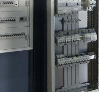
2 II With its extensive ranges, the Legrand offer meets your quality standards and provides real freedom and simplicity of installation together with acknowledged reliability. XL³ 400 and XL³ 800 cabinets and enclosures enable you to make optimum use of Legrand s concept of product integration. Whichever enclosure you choose, and whatever your preferred way of working and the technical requirements of your installations, you will fi nd what you need in the XL³ range. XL³ 400 and XL³ 800 cabinets and enclosures offer a wide range of solutions and innovations for quick, safe assembly: - Metal or insulated enclosures (IP and IP 55) - Products delivered dismantled (except for IP 55), providing total accessibility for wiring - Optimised equipment for easy installation - Sealable faceplates with metal ¼ turn fastening and handles - Screw-mounting faceplates that can be fi tted with hinges - Fast vertical or horizontal joining using 4 screws/nuts
3 CONTENTS The XL³ 400 et XL³ 800 ranges > > > > > > > > > > > > > >2 Assembling the enclosures XL³ 400/800 IP cabinets and enclosures > > > > > >8 XL³ 400 insulated cabinets > > > > > > > > > > > > > > > > > > > > >16 XL³ 800 IP 55 cabinets and enclosures > > > > > > > > > > > > >18 Mounting the distribution systems Optimised distribution VX³ busbars > > > > > > > > > > > > > > > > > > > > > > > > > > > > > >22 HX³ row distribution blocks > > > > > > > > > > > > > > > > > > > >25 HX³ and VX³ distribution blocks with automatic terminals Mounting VX³ busbars at the back of the enclosure > > > > >26 Mounting VX³ busbars in cable sleeves > > > > > > > > > > > > >29 Equipping HX³ 250 and 400 A row distribution blocks > > > > > >32 Mounting HX³ plug-in distribution blocks > > > > > > > > > > >36 Mounting HX³ and VX³ distribution blocks with automatic terminals > > > > > > > > > > > > > > > > > > > > > > > > > > > > > > >38 Standard distribution Standard distribution at the back of the enclosure > > > > > >40 Standard distribution in cable sleeves > > > > > > > > > > > > >43 Other distribution devices > > > > > > > > > > > > > > > > > > > > >45 Mounting the devices Principle for defining the required space > > > > > > > > > > > >46 French tariff connection plate > > > > > > > > > > > > > > > > > >52 Wiring the panels Cable entry > > > > > > > > > > > > > > > > > > > > > > > > > > > > > >54 Wiring > > > > > > > > > > > > > > > > > > > > > > > > > > > > > > > > >55 Protective conductors > > > > > > > > > > > > > > > > > > > > > > >57 Output terminal blocks > > > > > > > > > > > > > > > > > > > > > > >59 Installing the enclosures Transport and handling > > > > > > > > > > > > > > > > > > > > > >60 Fixing the enclosures > > > > > > > > > > > > > > > > > > > > > > > >61 Dimensions > > > > > > > > > > > > > > > > > > > > > > > > > > > > > >63 Accessories > > > > > > > > > > > > > > > > > > > > > > > > > > > > > >65 XL³ 400/800 WORKSHOP SPECIFICATIONS 1
 for installation in public buildings Rated short-time withstand current Icw: 25 ka -")
4 THE XL³ 400 AND XL³ 800 RANGES XL³ 400 and XL³ 800 can be used to create enclosures suitable for all your environments. GENERAL CHARACTERISTICS IP 30 to IP 55 IK 04 to IK 08 Class I and class II Fire resistance: 750 /5 s (IEC ) for installation in public buildings Rated short-time withstand current Icw: 25 ka - 1 s Max. short-circuit current Ipk: 50 kâ 24 or 36 modules per row Take devices up to 400 A for XL³ 400 (250 A for IP 55) and up to 800 A for XL³ 800 (630 A for IP 55) Choice of distribution: standard or optimised Internal or external cable sleeves (can be joined on the left or the right) Colour: RAL 7035 Conform to standard IEC module XL³ 800 metal enclosure with internal cable sleeve height mm XL³ 400 insulated cabinet height 1200 mm XL³ 400 one-piece IP 55 cabinet height 1115 mm 2


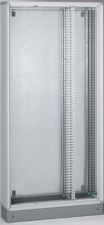
5 REMOVABLE CORNER PIECES REMOVABLE SIDE PANELS FACEPLATE WITH 1/4 TURN OR SCREW LOCKING FUNCTIONAL UPRIGHTS EXTERNAL CABLE SLEEVE PLINTH REVERSIBLE DOOR XL³ 400/800 WORKSHOP SPECIFICATIONS 3
6 THE XL³ 400 AND XL³ 800 RANGES XL³ 400 IP METAL CABINETS AND ENCLOSURES Depth: 175 mm External width: 575 mm (see dimensions on page 63) XL³ 400 METAL CABINETS ENCLOSURES External height (mm) Height for faceplates (mm) Cat.No Curved door Flat door solid glass Cable sleeve Solid door for cable sleeve
7 XL³ 400 IP INSULATED CABINETS Total depth: 175 mm (without door) Total width: 575 mm (see dimensions on page 63) XL³ 400 INSULATED CABINETS Total height (mm) Height for faceplates (mm) Cat.No Curved door Flat door solid glass Cable sleeve Solid door for cable sleeve XL³ 400 ONE-PIECE IP 55 CABINETS Total depth: 215 mm (with door) Total width: 650 mm (see dimensions on page 63) XL³ 400 IP 55 CABINETS External height (mm) Height for faceplates (mm) Cat.No XL³ 400/800 WORKSHOP SPECIFICATIONS 5
8 THE XL³ 400 AND XL³ 800 RANGES XL³ 800 METAL CABINETS AND ENCLOSURES IP 43 - IK 08 with kit and door IP 40 - IK 08 with door IP 30 - IK 07 without door Total depth: 230 mm (without door) (see dimensions on page 64) XL³ 800 METAL CABINETS ENCLOSURES External height (mm) Height for faceplates (mm) External width Number of modules / row Cat.No solid Curved door glass Internal cable sleeve kit Faceplate for internal cable sleeve External cable sleeve Door for external cable sleeve Faceplate with cut-outs for external cable sleeve DPX 250/ DPX-IS
9 XL³ 800 IP 55 CABINETS AND ENCLOSURES IP 55 - IK 08 with door Total depth: 250 mm (with door) (see dimensions on page 64) XL³ 800 IP 55 CABINETS ENCLOSURES External height (mm) Height for faceplates (mm) External width Number of modules / row Cat.No Flat door solid glass Internal cable sleeve kit Faceplate for internal cable sleeve External cable sleeve Door for external cable sleeve Faceplate with cut-outs for external cable sleeve DPX 250/ DPX-IS Side panels XL³ 400/800 WORKSHOP SPECIFICATIONS 7


10 ASSEMBLING THE ENCLOSURES XL³ 400/800 IP METAL CABINETS AND ENCLOSURES Metal cabinets, enclosures and cable sleeves are supplied dismantled. Each enclosure consists of a back, two functional uprights joined to the back, four corner pieces, four side panels and a cable entry plate. Enclosures more than mm high are supplied with a 100 mm plinth. XL³ 400 XL³ 800 The assembly is supplied dismantled, for minimum dimensions All the enclosures are supplied with an adjustable insulated cable entry plate The functional uprights integrated at the back of XL³ 400 and XL³ 800 enclosures have two fixing heights, for quick, reliable fixing of all equipment. 8


11 1 ASSEMBLING THE BACK AND THE CORNER PIECES 2 FITTING THE SIDE PANELS XL³ 800 XL³ 400 Insert the corner pieces in the functional uprights Insert the side panels in the top of the corner runners. XL³ 800 XL³ 400 Slide the side panels in steadily until they are inserted in the back. then attach them with a single M6 x 10 screw M6 screws Standardised screws: a screwdriver and a 10 mm spanner are all that is required for complete assembly of the enclosures. The side panels have a cut-out for fitting cable entry plates and for feeding the wiring through when joining enclosures. XL³ 400/800 WORKSHOP SPECIFICATIONS 9


12 ASSEMBLING THE ENCLOSURES 3 MOUNTING AN INTERNAL CABLE SLEEVE (XL³ 800 ONLY) 4 JOINING ENCLOSURES 5 ASSEMBLING THE PLINTHS 36-module wide XL³ 800 cabinets and enclosures can be fitted with an internal cable sleeve using kits Cat.No /27/28/29. These kits consist of an intermediate functional upright, two spacers and a faceplate support upright. The cable sleeve can be installed on the right or the left. No accessories are needed for joining cabinets and enclosures. As when joining enclosures, the corner piece seals must be removed before assembling the plinths. To fix the functional upright on the crosspieces at the back of the enclosure, insert 4 clip-nuts in the marked holes. Remove the seals from the corner pieces and join the enclosures using the four M6 screws and four nuts provided. Care must be taken to use the correct holes Fix the two sides of the plinth using the four M6 screws and four nuts provided. The front and rear covers of the plinth are attached using four self-tapping screws. Fix the spacers at the ends of the functional upright, then fix the faceplate support on the spacers. Horizontal and vertical joining can be used together 10 The plinths can be placed on top of one another for easier cable spreading.


![Enclosures < 900 mm high (XL³ 400 only) [2] [1] Release the two linking](/docs-images/75/72114409/images/13-7.jpg "rings from the connecting rods and the mechanism.")

13 6 MOUNTING THE DOORS The direction in which the door opens determines the side on which the hinges and latches are fitted. Enclosures 1550 mm high To mount the doors, the enclosures must be fitted with 3 hinges on one side and 2 latches on the other. Enclosures 900 to 1200 mm high The doors are fitted with a central handle with 2-point lock. For an optimum finish, insert the dummy strips in the hinge opening. Enclosure equipped for opening to the right. To reverse the way the door opens, fit the hinges on the left and the latches on the right. The door itself will be turned round 180 degrees. The mechanism which operates the connecting rods must also be dismantled and turned round 180 degrees. 1 2 The door can open to the right or the left, depending on which side the hinges and latches have been fitted. Enclosures < 900 mm high (XL³ 400 only) [2] [1] Release the two linking rings from the connecting rods and the mechanism. The door is opened in 2 steps: 1 - Disengage 2 - Rotate To mount the doors, fit the enclosures with two hinges on one side and a door release on the other. Unscrew the two screws fixing the handle and the mechanism. Reverse the connecting rods, then reassemble the mechanism in the same way. It is essential to fit the metal bracket so that the handle locks correctly. XL³ 400/800 WORKSHOP SPECIFICATIONS 11

 Small")
 the")


14 ASSEMBLING THE ENCLOSURES 7 FITTING THE KEY BARRELS The method differs according to the type of handle used. Large handles (enclosures 1550 mm high) Small handles (enclosures < 1550 mm high) Once the handle has been dismantled (M6 screw) the blanking plate is automatically released. Push in the two black clips to remove the blanking plate Combine the adaptor casing and barrel assembly with the black adaptor. Refit the handle on its support. Combine the adaptor casing and barrel assembly with the aluminium adaptor. Insert the pin in the notch towards the front. door. The self-adhesive document holder Cat.No is attached on the inside of the Insert the assembled barrel in the body of the handle. Insert the assembled barrel in the body of the handle. 12

, height 200 mm, at the top and/or bottom of the XL³ 800 enclosure provides")


15 8 FACEPLATES Faceplates for cabinets and enclosures There are two versions of metal faceplate: - ¼ turn locking, for 24-module XL³ 400 and XL³ Screw locking, for 24 and 36-module XL³ 800 The ¼ turn faceplates are sealable. 150 mm 50 mm 50 mm 100 mm 25 mm 150 mm Installing ventilating faceplates Cat.No and (24 and 36 modules), height 200 mm, at the top and/or bottom of the XL³ 800 enclosure provides natural ventilation for heat dissipation. Example of the installation of the clip-nuts for three faceplates, heights: 150, 50 and 200 mm. The 1st clip-nut is always positioned in the 1st hole. The screw-mounting faceplates are supplied with captive screws and clip-nuts which must be fitted on the faceplate support uprights. The screw-mounting faceplates can be fitted with hinges Cat.No on the right or the left. 25 mm 200 mm 50 mm 25 mm The screws are always positioned 25 mm from the top and bottom of the faceplate. XL³ 400/800 WORKSHOP SPECIFICATIONS 13


16 ASSEMBLING THE ENCLOSURES 9 EQUIPOTENTIAL LINK FOR THE DOOR AND FACEPLATES Cable sleeve faceplates The cable sleeves take solid metal faceplates. They are supplied with hinges and locks which can be fitted on the left or the right. The fixing positions for the clip-nuts on the faceplate support upright are given below. The faceplate hinges can be fitted on the right or the left If control and signalling units with voltage U > 50 V are fitted, the doors are equipped with studs for connecting the equipotential link conductor Cat.No Insert the two locks in the cutouts on the front cover on the side opposite the hinges and fix them using the nuts provided. Conductor Cat.No has an eyelet terminal at each end. Feed the conductor behind the hinge to avoid getting in the way of the faceplate. Faceplates 1400 mm high have cut-outs for DPX 250, 630 with or without e.l.c.b. underneath or DPX-IS 630. Fixing positions for hinges and clip-nuts (in mm) The equipotential link for ¼ turn faceplates is provided by the latch bolt. The earth terminal is only provided when devices are mounted on the faceplate Height (mm) Cat.No


17 10 OBTAINING IP 43 PROTECTION IP 43 is obtained by installing a door fitted with seal Cat.No and the insulated cable entry plate supplied with the enclosure. The plate is fitted after the upper side panel has been cut. The seal must be fitted in the bottom of the door. XL³ 400/800 WORKSHOP SPECIFICATIONS 15


18 ASSEMBLING THE ENCLOSURES XL³ 400 INSULATED CABINETS Like the metal cabinets, XL³ 400 insulated cabinets and cable sleeves are supplied dismantled in reusable packaging. Each enclosure consists of a back, four corner pieces, four side panels and a faceplate frame in four separate parts. The metal back, joined to the functional uprights, provides optimum rigidity. Inside it is fitted with an insulated backplate which can take C-section busbars Cat.No /31 and supports Cat.No /38 to create VX³ optimised busbars. It is insulated at the back to ensure it is class II. All the other parts of the enclosure are made of insulated plastic. 1 ASSEMBLING THE CABINETS AND CABLE SLEEVES As with metal enclosures, each corner piece is inserted in the functional uprights and attached using an M6 screw (see page 9). The side panels are fitted by sliding them in the corner runners. They are held in place by the faceplate frame. Each side of the frame is attached separately to the corner pieces by 2 Phillips screws The backs of the insulated cabinets are ready to take C-section busbars to create an active backplate. 16
. For the cable feedthroughs, simply do not mount the side panels.")
. Insulated faceplates, like metal faceplates, have a sealable ¼ turn lock.")

19 2 JOINING THE ENCLOSURES 3 MOUNTING THE DOORS 4 FACEPLATES Cabinets and cable sleeves are joined horizontally or vertically in the same way as for metal enclosures (see page 10). For the cable feedthroughs, simply do not mount the side panels. The methods for mounting and reversing the doors are exactly the same as those for metal enclosures (see page 11). Fitting the seal Cat.No /32 on the door provides IP 43 protection (see page 15). Insulated faceplates, like metal faceplates, have a sealable ¼ turn lock. The shape of the faceplates is specially designed for ease of handling. The blanking plates for the unused hinge positions are held in place by a screw, which can be inserted without any tool. 5 COMPLIANCE WITH CLASS II Joining a cabinet and a cable sleeve To comply with class II, replace the plastic covers that are supplied to insulate the fixing screws. XL³ 400/800 WORKSHOP SPECIFICATIONS 17


20 ASSEMBLING THE ENCLOSURES XL³ 800 IP 55 CABINETS AND ENCLOSURES XL³ 800 IP 55 cabinets, enclosures and cable sleeves are one-piece metal enclosures. They have cable gland plates at the top and bottom, and side openings for creating assemblies by horizontal joining. They are supplied without side panels. They take solid rounded metal or glass doors (to be ordered separately). The enclosures (H 1595 mm) are supplied with a 100 mm plinth. The cabinets and enclosures are available in two widths: 24 and 36 modules. The 36-module enclosures can take an internal cable sleeve. 1 FITTING THE SIDE PANELS The side panels are supplied in pairs, with their weatherproof seals fitted, and with their fixing screws and plastic blanking plates. The ease of joining XL³ 800 enclosures together provides a great deal of freedom for creating IP 55 distribution assemblies It is essential to fit the blanking plates in the joining holes to ensure IP 55 protection. 18

. The plinths are also available separately (Cat.")
21 2 JOINING THE ENCLOSURES 3 ASSEMBLING THE PLINTH The enclosures are mechanically linked using joining kits Cat.No The weatherproof seal is obtained by fitting the self-adhesive seal Cat. No beforehand. Number of joining kits Cat.No according to the height of the enclosures Height Quantity Usable dimensions of the side opening according to the height of the enclosures l H l h Enclosures and external cable sleeves are supplied with their plinths (height 100 mm). The plinths are also available separately (Cat.No /61/62, respective widths 700 and 950 mm, and 500 mm for cable sleeve). They can be placed on top of one another to make the enclosures higher. If enclosures are joined horizontally, a space can be made between the plinths (pre-cut 135 x 65 mm opening on both sides) H h Attach the seal to the bottom A seal must be fitted on each enclosure The opening is made using a hammer. Insert the clip-nuts on the upright then attach the bracket using two M6 screws. XL³ 400/800 WORKSHOP SPECIFICATIONS 19

22 ASSEMBLING THE ENCLOSURES 4 MOUNTING AN INTERNAL CABLE SLEEVE 5 CABLE GLAND PLATES 6 MOUNTING THE DOORS 36-module IP 55 cabinets and enclosures can be converted to 24 modules with an internal cable sleeve on the right or the left, using kits Cat.No /27/28/29. The top and bottom of the enclosures are equipped with cable gland plates. These are fixed using self-tapping screws. The enclosures are supplied with the hinges and door releases fitted. The doors of cabinets (H < 1595 mm) are supplied with two locking handles (to be fitted). TOP L modules: L = 496 mm 36 modules: L = 714 mm External cable sleeve: L = 274 mm An internal cable sleeve is mounted in exactly the same way as for IP 30 enclosures (see page 10). BOTTOM Usable dimensions of the cable feedthroughs (mm). The cabinets are fully reversible:the direction of opening can be changed by simply turning the cabinet upside down or reversing the hinges and door releases. The doors of the enclosures (H 1595 mm) are supplied with a connecting rod assembly and a central handle (to be fitted). For enclosures the direction of opening is changed by reversing the door: the hinges and door releases are identical. The handles are fitted and reversed in exactly the same way as for IP 30 enclosures (see page 11). 20

. The doors are easy to mount: simply fit the hinge pins.")
23 7 DOOR EQUIPOTENTIAL LINK If control and signalling units whose voltage is higher than 50 V are fitted, it is essential to create the door equipotential link using the integrated stud. Insert the conductors in the enclosure via a solid faceplate fitted with a cable gland Cat.No (hole Ø 23 mm). The doors are easy to mount: simply fit the hinge pins. XL³ 400/800 WORKSHOP SPECIFICATIONS 21

24 MOUNTING THE DISTRIBUTION SYSTEMS Optimised distribution XL³ 400 and XL³ 800 enclosures give users freedom to organise the distribution. With VX³ busbars and HX³ optimised row distribution blocks, Legrand provides a complete, coherent system for horizontal and vertical distribution. This distribution system increases safety and assists with quick installation and optimisation of the space in the enclosure. VX³ BUSBARS BUSBARS AT THE BACK OF ENCLOSURES POWER SUPPLY KITS These kits, consisting of prefabricated copper connections, supply the VX³ busbar from the main device. ISOLATING SUPPORTS These are fixed at the back of the enclosure on the functional uprights. They take aluminium C-section busbars. The lug supports make it easy to mount the bars. In XL³ 400 enclosures, an insulated backplate is required for mounting the busbar. TINNED COPPER ALUMINIUM BUSBARS Their surface treatment ensures electrolytic compatibility with copper and durability of the contacts. Their C-section enables connection without any drilling, using the special hammer head bolts and tap-off terminals. ISOLATING PROFILES These ensure IP XXB protection. 22

25 BUSBARS IN CABLE SLEEVES POWER SUPPLY KITS These kits, consisting of prefabricated copper connections, supply the VX³ busbar from the main device. ISOLATING SUPPORTS These are mounted in cable sleeves on the functional uprights. They take aluminium C-section busbars. The lug supports make it easy to mount the bars. TINNED COPPER ALUMINIUM BUSBARS Their surface treatment ensures electrolytic compatibility with copper and durability of the contacts. Their C-section enables connection without any drilling, using the special hammer head bolts and tap-off terminals. CONNECTION KITS Prefabricated connections for supplying HX³ 250 and 400 A row distribution blocks and protection devices without any bending or drilling. XL³ 400/800 WORKSHOP SPECIFICATIONS 23
26 MOUNTING THE DISTRIBUTION SYSTEMS PRODUCT SELECTION BUSBAR AT BACK OF XL³ 400/800 ENCLOSURE 1 POWER SUPPLY KIT (VERTICAL MAIN DEVICE IN ENCLOSURE) Enclosure DPX³ 160 DPX³ 250 DPX 630 DPX 1600 (1) DPX-IS 250 DPX-IS 630 XL³ XL³ BUSBARS AT THE BACK OF ENCLOSURE Enclosure XL³ 400 XL³ 800 Insulated backplate Isolating support Isolating lug support Isolating profiles Tinned copper aluminium C-section busbars Complete 400 A kit: 1 XL³ 400 enclosure height 1900 mm + 1 insulated backplate + 3 isolating supports + 1 lug support + 4 x 400 A bars + 1 set of IP 2X isolating profiles 250 A A A BUSBAR IN XL 3 400/800 CABLE SLEEVE POWER SUPPLY KIT (VERTICAL 1 2 DEVICE IN CABLE SLEEVE) POWER SUPPLY KIT (HORIZONTAL DEVICE IN ENCLOSURE) 1 Enclosure DPX³ 160 DPX³ 250 DPX 630 DPX³ 160 DPX³ 250 DPX 630 DPX 1600 (1) XL³ XL³ BUSBARS IN CABLE SLEEVE Enclosure XL³ 400 XL³ 800 Isolating support Isolating lug support Tinned copper aluminium C-section busbars 250 A A A CONNECTION KIT Device in horizontal position HX³ row distribution block Enclosure DPX³ 160 DPX³ 250 DPX 630 with power supply module Cat.No XL³ XL³ (1) Limited to 800 A 24
 or via a head of row device.")

 is used to insert control devices in the row.")
27 HX³ ROW DISTRIBUTION BLOCKS HX³ 250 AND 400 A 4-POLE DISTRIBUTION BLOCKS The distribution block can be supplied directly via a VX³ busbar (with or without connection accessories, depending on the configuration) or via a head of row device. Rated voltage (Ue): 230/400 V± Rated frequency: 50/60 Hz Permissible short-circuit current (Ipk): 52 kâ Insulation voltage (Ui): 1000 V Rated current: 250/400 A maximum (central power supply) Protection index: IP 20 Maximum connection cross-section for the power supply module: flexible bars 32 x 4 mm ROW DISTRIBUTION BLOCK SUPPORT BASES FOR DPX³ CIRCUIT BREAKERS For fixing and connecting 3P and 4P DPX³ 160 and 250 circuit breakers and RCBOs. SUPPORT BASES FOR MODULAR DEVICES For fixing and connecting 1P, 2P, 3P and 4P DX³ 1 module/pole and 1.5 module/pole circuit breakers. A 1-module universal support base (without connections) is used to insert control devices in the row. HX³ 80 AND 125 A PLUG-IN 4-POLE DISTRIBUTION BLOCKS Tool-free installation on 2-position aluminium 3 rails. Rated voltage (Ue): 230/400 V± Rated frequency: 50/60 Hz Permissible short-circuit current (Ipk): 25 kâ Insulation voltage (Ui): 690 V± Rated current: A maximum, direct connection on power supply module - 80 A maximum, direct connection on modular device Protection index: IP 20 Maximum connection cross-section of power supply module: 50 mm ROW DISTRIBUTION BLOCK 4-POLE POWER SUPPLY MODULE Supplied with the distribution block, for direct power supply of the block via screw terminals. Power can also be supplied direct by a head of row device supplied via its upstream terminals. CONNECTION MODULES For mounting on Legrand DX³ 1P+N, 2P, 3P and 4P circuit breakers, used for automatic connection to the distribution block. The phase to be connected is selected by the choice of connection module. HX³ AND VX³ DISTRIBUTION BLOCKS WITH AUTOMATIC TERMINALS HX³ and VX³ distribution blocks with automatic terminals are used for the vertical power supply and horizontal distribution of modular rows. These distribution blocks are designed to provide IP XXB protection. VX³ 125 A AUTOMATIC Rated voltage (Ue): 230/400 V± Rated frequency: 50/60 Hz Permissible short-circuit current (Ipk) : 30 kâ Insulation voltage (Ui): 500 V± Protection index: IP 20 HX³ 125 A AUTOMATIC Rated voltage (Ue): 230/400 V± Rated frequency: 50/60 Hz Permissible short-circuit current (Ipk): 20 kâ Insulation voltage (Ui): 500 V± Impulse voltage Uimp: 6 kv - degree of pollution 3 Rated current: 125 A Protection index: IP 20 XL³ 400/800 WORKSHOP SPECIFICATIONS 25


 Ipk (ka) Icw (ka) D (mm) 7 5 1600 17 10 1600 30 15 1000 40 20 800 52 25 600 In XL³ 800 enclosure (supports")
 Ipk (ka) Icw (ka) D (mm) 30 15 1600 40 20 1000 52 25 800 63 30 700 73 35 600 84 40 500 94 45 400 105 50 400 1")

28 MOUNTING THE DISTRIBUTION SYSTEMS MOUNTING VX³ BUSBARS AT THE BACK OF THE ENCLOSURE Optimised distribution at the back of the enclosure is created using aluminium C-section busbars equipped with an insulated backplate for XL³ 400 or isolating profiles for XL³ 800. These are all held in place by supports. MAXIMUM DISTANCES BETWEEN SUPPORTS ACCORDING TO THE PEAK CURRENT In XL³ 400 enclosure (supports Cat.No /38, busbars Cat.No /31) Ipk (ka) Icw (ka) D (mm) In XL³ 800 enclosure (supports Cat.No /61, busbars Cat.No ) Ipk (ka) Icw (ka) D (mm) MOUNTING THE BUSBAR In XL³ 400 Fit the lug support Cat.No at the back of the enclosure. Supports Cat.No /38 have markings, for ease of installation. The bottom of the enclosure is indicated by an arrow. Place the insulated backplate Cat.No and the aluminium C-section bars in position. Then install the intermediate supports to hold the busbars firmly in place. In XL³ 800 Fix the lug support Cat.No at the back of the enclosure and insert the spacers on which the busbars will be supported. 26


29 2 SUPPLYING THE BUSBAR The prefabricated power supply kits save time and are easy to mount for the various different main devices. Screw in the front of the lug support but do not fully tighten the screws. Screw in the front of the supports to hold the busbars firmly in place. Do not forget to fully tighten the screws on the lug support. Position the main device on its plate. Install the intermediate supports Cat. No without fitting the front. IP XXB protection is obtained by installing the isolating profiles Cat.No on aluminium C-section busbars. The kits are connected on the busbar using the hammer head bolts supplied with the kits. Position the aluminium C-section busbars so that they are supported on the lug support. For the maximum distances between supports, refer to the table on the previous page and to the instructions for the busbar supports. Fit the IP XXB protective cover supplied with the kit. XL³ 400/800 WORKSHOP SPECIFICATIONS 27


30 MOUNTING THE DISTRIBUTION SYSTEMS 3 MOUNTING HX³ 250 AND 400 A ROW DISTRIBUTION BLOCKS The HX³ row distribution block takes the bases for DPX³ and DX³. There are two catalogue numbers for mounting on busbars at the back of the enclosure, depending on the type of enclosure: XL³ 400: HX³ 250 A row distribution block Cat.No XL³ 800: HX³ row 400 A distribution block Cat.No Do not forget to fit the isolating profiles on the busbars for IP XXB protection. 4 TAP-OFF TERMINALS All other types of devices with currents I 250 A must be connected to the busbar by IP 2X tap-off terminals Cat.No (400 A busbars) or Cat.No (800 A busbars). Tightening torque 20 Nm Position the row distribution block and fix it on the functional uprights of the enclosure. For vertical positioning of the distribution block in the enclosure, see page 50. Insert the screw covers fully to provide IP XXB protection. This terminal is used for connecting two conductors and provides IP XXB protection with the screw cover inserted. The row distribution blocks are preequipped with hammer head bolts. Tighten them to connect the block to the busbar. For the installation of devices on the distribution block, see page

 Ipk (ka) Icw (ka) D (mm) dep. on bar Cat. No.")

 or internal")
 to the bottom of the uprights in the cable sleeve using clip-nuts and M6 screws.")
31 MOUNTING VX³ BUSBARS IN CABLE SLEEVES This type of optimised distribution consists of equipping the cable sleeve with aluminium C-section busbars, all held in place by supports. MAXIMUM DISTANCES BETWEEN SUPPORTS ACCORDING TO THE PEAK CURRENT In XL³ 400 enclosure (supports Cat.No /51) Ipk (ka) Icw (ka) D (mm) dep. on bar Cat. No In XL³ 800 enclosure (supports Cat.No /61, busbars Cat.No ) Ipk (ka) Icw (ka) D (mm) MOUNTING THE BUSBAR Isolating supports are used to create a staggered busbar at the back of external cable sleeves (up to 800 A) or internal cable sleeves (up to 400 A). Attach the lug support Cat.No (XL³ 400) or Cat.No (XL³ 800) to the bottom of the uprights in the cable sleeve using clip-nuts and M6 screws. Position the lugs in each compartment. Then fit the other isolating supports Cat.No (XL³ 400) or Cat.No (XL³ 800), then position the aluminium C-section busbars. Fit the front of the support but do not fully tighten the screws. Tighten the screws on the front of the support (tightening torque 6 Nm). Do not forget to tighten the lug support fully. XL³ 400/800 WORKSHOP SPECIFICATIONS 29


.")

.")
32 MOUNTING THE DISTRIBUTION SYSTEMS 2 CONNECTING THE MAIN DEVICE The main device can be mounted in the cable sleeve or in the enclosure. Main device mounted in enclosure Main device mounted in cable sleeve In this type of mounting, the main device will be positioned horizontally in the enclosure and will be connected to the busbar using the special prefabricated kit. Once the main device has been mounted in the enclosure, connect the various bars in the connection kit to the busbar. The principle is the same as for distribution at the back of the enclosure (see page 27). The device is fixed on its plate and mounted in the cable sleeve. Then use the special prefabricated connection kits to connect it to the busbar. It will be necessary to cut some of the bars in the kit in order to connect them correctly, depending on the position of the cable sleeve (right or left). To do this, pre-position the bars in order to identify the mark indicating where to cut. Strip a sufficient length. You can use the part that has been cut off as a reference. Cut the bar at the mark. As the busbars are predrilled, all you have to do is connect the main device to the busbar using hammer head nuts. 30


33 3 CONNECTING THE OUTGOING LINE PROTECTION DEVICES 4 MOUNTING HX³ 250/400 A ROW DISTRIBUTION BLOCKS The principle is the same as for connecting the main device. INCOMING POWER SUPPLY MAIN DEVICE The HX³ row distribution block takes the bases for DPX³ and DX³. There are two catalogue numbers for mounting in an enclosure with power supply in a cable sleeve, depending on the type of enclosure: XL³ 400: HX³ 250 A row distribution block Cat.No XL³ 800: HX³ 400 A row distribution block Cat.No Position the row distribution block and fix it on the functional uprights of the enclosure. OUTGOING LINES OUTGOING LINE PROTECTION DEVICES PREFABRICATED CONNECTION KITS Position and lock the side-mounting power supply module for the row distribution block (Cat.No ) on the side of the cable sleeve on which the busbar is located. Then connect the power supply module to the busbar using the prefabricated connection kit. XL³ 400: Kit for HX³ 250 A row distribution block Cat.No XL³ 800: Kit for HX³ 400 A row distribution block Cat.No As for the other devices, it will be necessary to cut some of the bars in the kit in order to connect them correctly, depending on the position of the cable sleeve (right or left) (see page 30). XL³ 400/800 WORKSHOP SPECIFICATIONS 31


 to be connected automatically to the row distribution")

34 MOUNTING THE DISTRIBUTION SYSTEMS EQUIPPING HX³ 250 AND 400 A ROW DISTRIBUTION BLOCKS 1 MOUNTING A DPX³ Circuit breakers are mounted on the HX³ distribution block using support bases. The four support bases for DPX³ enable 3P and 4P DPX³ 160 and DPX³ 250 A circuit breakers to be connected automatically. A) MOUNTING THE CIRCUIT BREAKER ON THE BASE B) INSTALLING THE ANTI-WITHDRAWAL KIT The anti-withdrawal kit prevents a circuit breaker being withdrawn in the closed position. Support bases for DPX³ Device DPX³ 160 DPX³ 250 3P P Install the movable part of the base, inserting the conductive parts into the upstream terminals of the DPX³ circuit breaker. Insert the spring Support bases for DPX³ consist of a fixed part, a movable part, an anti-withdrawal kit and two terminal shields. They enable a DPX³ 160 or 250 (when off-load) to be connected automatically to the row distribution block while energised. Secure the device to the base using the fixing screws supplied with the DPX³. then assemble the two parts of the kit. 160 A 250 A When mounting a DPX³ 160, the upstream cage terminals must first be removed from the device. Make the upstream electrical connections with the screws supplied with the circuit breaker (no. 4 Allen key, tightening torque 7 N m). Fix the kit on the back of the movable part of the support base with the two screws supplied (tightening torque 1 N m). 32


35 C) FITTING THE TERMINAL SHIELDS D) MOUNTING THE DPX³ ON THE DISTRIBUTION BLOCK The DPX³ equipped with a support base can be installed on the 400 A row distribution block while energised. Clip the DPX³ on this base in open position. Engage the rear part of the terminal shield then push it down at the front. Position the fixed part of the support base on the row distribution block. Lock the assembly with the top and bottom ¼ turn screws. It is locked automatically. Lock the terminal shield by inserting the 2 sealed plugs. For downstream connection of the DPX³, the downstream terminal shield must be removed. XL³ 400/800 WORKSHOP SPECIFICATIONS 33

 MOUNTING DX³ ON WIRED BASE This type of base is used to connect modular devices with screw terminals and either 1 or 1.")


36 MOUNTING THE DISTRIBUTION SYSTEMS 2 MOUNTING DX³ CIRCUIT BREAKERS Installing modular circuit breakers on the HX³ 400 A distribution block requires the use of support bases for DX³. They raise modular circuit breakers to the same height as DPX³, so that they can be installed together on the same row. A) MOUNTING DX³ ON WIRED BASE This type of base is used to connect modular devices with screw terminals and either 1 or 1.5 modules per pole, depending on the catalogue number chosen. The circuit breakers do not require any preparation. Wired bases for DX³ Device Connection 1 mod/pole 1.5 mod/pole L P L L N P L1, L2, L P L1, L2, L3, N Connect the wires in the circuit breaker without installing it on the rail part of the support base. Recommended tightening torque: 2.5 N m for DX³ with 1 module/pole 5.5 N m. for DX³ with 1.5 module/pole Engage the device in the same way as on a standard modular rail. Complete the installation by locking the circuit breaker clips. To prevent any risk of contact with live parts, the wires must be connected to the circuit breaker before the base is installed on the distribution block. Holding the circuit breaker with one hand, clip the base onto the distribution block and lock it using the locking levers. DX³ devices compatible with modular bases Devices Plug-in bases Wired bases 2P and 4P DX³-ID RCCBs outgoing lines via the bottom 2P and 4P DX³ RCBOs protection of outgoing lines 1P, 2P, 3P and 4P DX³ circuit breakers 1 module/pole 1P, 2P, 3P and 4P DX³ circuit breakers 1.5 modules/pole 34


.")


37 3 INSTALLING SUPPORT BASES FOR DX³ A) MOUNTING DX³ CIRCUIT BREAKERS ON PLUG-IN BASE The connection module is mounted via the rear of the circuit breaker. Plug-in (wireless) bases for DX³ are intended for devices with 1 module per pole which are connected via the rear of the circuit breaker. Plug-in bases for DX³ Device Connection 1 mod/pole L P L L N P L1, L2, L P L1, L2, L3, N Position the upper part of the connection module (marked Max 80 ) on the top of the circuit breaker then push it forward to engage the module pin in the device's plug-in mechanism. This mechanism ensures the contact pressure is correct. Then do the same for the other poles. Then push on the circuit breaker to clip it onto the base, and lock it with the clips. Further circuit breakers can be added while energised but off-load (circuit breaker in open position). The plug-in bases are supplied with the corresponding connection modules which must be installed first on the circuit breakers. The circuit breaker is correctly installed once it is locked on the rail. Clip the base on the distribution block There are four colours of connection module corresponding to the four poles on the row distribution block. Blue Brown Grey Black Neutral Phase 1 Phase 2 Phase 3 This enables the required phase to be selected. It is thus very easy to balance the phases on the whole row. then lock the assembly using the levers. XL³ 400/800 WORKSHOP SPECIFICATIONS 35
 up to 80 A by direct connection to a circuit breaker or")


38 MOUNTING THE DISTRIBUTION SYSTEMS MOUNTING HX³ PLUG-IN DISTRIBUTION BLOCKS The HX³ plug-in row distribution block is used for 4-pole distribution of DX³ devices (1 module per pole) up to 80 A by direct connection to a circuit breaker or 125 A with the power supply module. With its IP XXB insulation, devices can be safely connected and disconnected automatically while the block is energised. Like the 250 or 400 A row distribution blocks, it provides total freedom to combine 1P+N, 1P, 2P, 3P and 4P DX³. It is mounted in XL³ 400 and XL³ 800 enclosures in the same way. HX³ plug-in 24 modules Cat.No HX³ plug-in 36 modules Cat.No A power supply module for HX³ plug-in Cat.No UP TO 80 A Indirect power supply of the distribution block via a head of row device UP TO 125 A Direct power supply of the distribution block via power supply module Cat.No fitted with its protective cover Can be connected and disconnected while energised but the circuit must be off-load (circuit breaker open). Direct power supply of the distribution block via the terminals of one of the devices Direct power supply of the distribution block via power supply module Cat.No equipped with a device 1 INSTALLING THE DISTRIBUTION BLOCK IN THE ENCLOSURE The HX³ plug-in distribution block is mounted directly on rails Cat.No /06/51 by simply clipping it on. Position the rail in the enclosure. 36
 Install the module in the same way as on automatic terminals so that the connection module's teeth are inserted in")


.")


39 2 FITTING THE CONNECTION MODULES 3 DISTRIBUTION BLOCK POWER SUPPLY 1P+N devices- 1 module Connection to the power supply module (up to 125 A) Install the module in the same way as on automatic terminals so that the connection module's teeth are inserted in the circuit breaker terminals, then tighten to the correct torque (1.6 to 2 N m). For 1P+N circuit breakers with automatic terminals, the connection module can be installed without any tools, simply by pressing down on it. Devices with 1 module per pole Cables up to 35 mm² can be connected to the power supply module. When its protective cover is removed, it can take a 4-pole device. When the power supply module is equipped with a device, this device must never be removed while energised. These are mounted in the same way as 250 and 400 A row distribution blocks (see page 35). Connection to the terminals of a device (up to 80 A) For 1P + N circuit breakers with screw terminals, the device's terminals must first be opened with a PZ screwdriver. Compatible modular devices 1P+N DNX³ circuit breakers 1 module screw or automatic terminals 1P+N DX³ RCBOs protection of outgoing lines 2P and 4P DX³-ID RCCBs incoming via the top/outgoing via the bottom 2P and 4P DX³ RCBOs protection of outgoing lines 1P, 2P, 3P and 4P DX³ circuit breakers 1 module/pole Connection modules (L1N, L2N, L3N) (L1, L2, L3, N) To supply the distribution block directly via the terminals of one of the devices, first break off the protective tabs on the connection modules. XL³ 400/800 WORKSHOP SPECIFICATIONS 37


40 MOUNTING THE DISTRIBUTION SYSTEMS MOUNTING HX³ AND VX³ DISTRIBUTION BLOCKS WITH AUTOMATIC TERMINALS VX³ and HX³ distribution blocks with automatic terminals are used for the vertical power supply and horizontal distribution of modular rows. These distribution blocks are designed to provide IP XXB protection. HX³ 125 A auto. term. - 1 row: Cat.No HX³ 125 A auto. term. - ½ row: Cat.No VX³ 125 A auto. term. - 4 rows: Cat.No VX³ 125 A auto. term. - 5 rows: Cat.No VX³ 125 A auto. term. - 6 rows: Cat.No MOUNTING A 125 A HX³ WITH AUTOMATIC TERMINALS HX³ distribution blocks are supplied with supports for mounting on rails Cat.No , and Power supply from one row to another is obtained by breaking the blanking plates located under the connection terminals. Position the supports on the bottom of the distribution block and clip them on. Strip back the cables 20 mm, and insert them in the terminals of the first distribution block. Position the distribution block on the rear of the rail and clip it on. Mount the assembly in the enclosure. Tighten the terminals of the first distribution block then connect the second block (tightening torque 3 Nm). 38 All that remains is to connect the power supply of the distribution block then connect the various outgoing lines.


41 2 MOUNTING A 125 A VX³ WITH AUTOMATIC TERMINALS 3 CONNECTING THE OUTGOING LINES VX³ distribution blocks are fixed on the functional uprights of the XL³ 400 enclosure. They can be mounted on the right or the left. Whether the HX³ or the VX³ automatic terminal distribution block is used, as the lines are connected via automatic terminals, simply use a screwdriver as a lever and insert the cable then remove the screwdriver. Lines are disconnected in the same way. Position the supports on the rear of the VX³ distribution block and screw them on. All that remains is to connect the power supply of the distribution block then connect the various outgoing lines. Caution: lines must not be connected or disconnected while the distribution block is energised. It is essential to switch off the power supply to the distribution blocks before carrying out any work. Fix the assembly on the uprights of the enclosure using clip nuts that have been fitted beforehand. To maintain IP XXB protection, it is essential to fit the protective covers on any unused power supply terminals. These terminals will be used when power is supplied from one distribution block to another. XL³ 400/800 WORKSHOP SPECIFICATIONS 39
42 MOUNTING THE DISTRIBUTION SYSTEMS Standard distribution STANDARD DISTRIBUTION AT THE BACK OF THE ENCLOSURE Standard distribution at the back of the enclosure can be created using vertical busbars with isolating supports Cat.No , or distribution blocks, with stepped distribution block Cat.No installed horizontally or extra-flat distribution block Cat.No MOUNTING THE VERTICAL BUSBAR Support Cat.No is used for creating busbars up to 400 A at the back of XL³ 400 and 800 cabinets and enclosures. Bars Selection of bars I (A) Cat.No Crosssection IP 30 IP > 30 (mm) x x x Maximum distance (D) between supports according to the peak current (Ipk) D (mm) SUPPORT Cat.No x 5 Bars (18 x 4) (25 x 5) (32 x 5) 32 x 5 PERFORATED FLAT BARS Cat.No /19/34 32 x 5 max. Peak Isc Ipk (kâ)


43 XL³ bar cross-sections on the same support 32 X 5 mm réf x 5 Start by fitting the 2 support retaining lugs on the bottom of the functional uprights using the clip-nuts and M6 screws provided. XL³ 400 Cut your bars to the required length and place them on the isolating supports, aligning them with the fixing holes. Bars 32 x 5 1/4 32 x 5 25 X 5 mm réf /4 25 x 5 Fix the isolating support on the 2 lugs using the two remaining M6 screws Extension pieces Cat.No must be used for mounting in the XL³ 800. XL³ 800 Once the correct position has been determined, fix the retaining crosspiece on the support with the 5 cheese head screws. Do not tighten these screws fully as the positions of the bars may be subsequently adjusted. Bars 25 x 5 18 X 4 mm réf x 4 25 x 5 1/4 18 x 4 Bars 18 x 4 Mounting on the bottom of the uprights for more space for connecting devices on the busbar. XL³ 800 Mounting on the bottom of the uprights for more space below the busbar and to allow insertion of cables. XL³ 400/800 WORKSHOP SPECIFICATIONS 41

.")
 it can be installed at the supply end")
 used with solid faceplate Cat.No 0 208 45 or Cat.")
44 MOUNTING THE DISTRIBUTION SYSTEMS 2 MOUNTING THE 400 A STEPPED DISTRIBUTION BLOCK CAT.NO HORIZONTALLY 3 MOUNTING THE 250 A EXTRA-FLAT DISTRIBUTION BLOCK CAT.NO IN XL³ 400 The 400 A stepped distribution block Cat.No consists of two isolating supports, four 32 x 4 mm tinned copper bars with protective cover and a protective screen. Each bar has 2 x Ø 8.5 mm smooth holes and 21 tapped holes with M6 screws for connection via terminals (70 mm² max.). Four insulated lugs are supplied for mounting the distribution block horizontally in XL³ 400 cabinets and enclosures. The protective covers are fitted on each bar using staples As the extra-flat distribution block has very high short-circuit resistance (60 kâ) it can be installed at the supply end of the panel. It can be installed next to a DPX 250 or 630 on fixing plate Cat.No Connections on plates, incoming: 150 mm² per pole, outgoing: up to 3 x 70 mm² per pole. In 24-module XL³ 800 enclosures, the distribution block is fixed horizontally on solid plate Cat.No (height 400 mm) used with solid faceplate Cat.No or Cat.No Install the 4 fixing lugs on the distribution block. 440 mm 250 Fixing centres of distribution block Cat.No Distribution block Cat.No saves a considerable amount of space in small cabinets. Fit the distribution block on the bottom profile of the functional uprights using clip-nuts and M6 screws. 42
 or external cable sleeve (XL³ 400).")
 0 374 18 25 x 5 330 270 Fix the busbar supports on the functional uprights of the cable sleeve using")
 between supports according to the peak current (Ipk) D (mm) Position the copper bars on the")
 374 34 (18 x 4) Bars 374 18 (25 x 5) 10 800 900 15 700 800 20 550 700 25 400 500 30 350 400 35 300 350 40 300 300 45 200 200 50")
45 STANDARD DISTRIBUTION IN CABLE SLEEVES 1 MOUNTING A STEPPED BUSBAR Isolating supports Cat.No are used to create a stepped busbar up to 400 A in an internal cable sleeve (XL³ 800) or external cable sleeve (XL³ 400). They are fixed on the functional uprights using clip-nuts and M6 screws. Bars Selection of bars I(A) Cat.No Crosssection IP 30 IP > 30 (mm) x Fix the busbar supports on the functional uprights of the cable sleeve using the clip-nuts and M6 screws provided. Insert the clip-nuts on the top profile of the uprights x Maximum distance (D) between supports according to the peak current (Ipk) D (mm) Position the copper bars on the supports. Each busbar support is supplied with an isolating screw for fitting a protective screen if required. Ipk (kâ) (18 x 4) Bars (25 x 5) Fix the copper bars on the supports using M6 hex. head screws with integral washer. Isolating screws XL³ 400/800 WORKSHOP SPECIFICATIONS 43

 0 374 18 25 x 5 330 270 0 374 19 32 x 5 450 400 Fixt the supports on the bottom profile of the functional uprights using clip-nuts and M6 screws (tightening torque")
 374 18 (25 x 5) 374 19 (32 x 5) Bars 374 40 (50 x 5) 374 41 (63 x 5) 10 800 900 15 600 600 700 800 20 450 500 600 700 25 350 400 500 550")
46 MOUNTING THE DISTRIBUTION SYSTEMS 2 MOUNTING A SLOPING BUSBAR Isolating supports Cat.No are used to create a sloping busbar up to 800 A in an external cable sleeve (XL³ 800). 3 MOUNTING THE 400 A DISTRIBUTION BLOCK CAT.NO VERTICALLY The 400 A distribution block can also be mounted vertically in an external cable sleeve (XL³ 400) or an internal cable sleeve (XL³ 800). Selection of bars Bars I(A) Cat.No Crosssection IP 30 IP > 30 (mm) x x Fixt the supports on the bottom profile of the functional uprights using clip-nuts and M6 screws (tightening torque 10 Nm) x x Maximum distance (D) between supports according to the peak current (Ipk) D (mm) Fix the distribution block directly on the top profile of the functional uprights using 4 clip-nuts and 4 M6 screws Ipk (kâ) (25 x 5) (32 x 5) Bars (50 x 5) (63 x 5) Fix the bars on the supports (tightening torque 7 Nm). The supports are supplied with 2 screws for fitting a screen (not supplied) 50 x 5-63 x mm 350 mm 25 mm 25 mm 25 x 5-32 x 5 M5 Ø 10,4 mm Ø 10,4 mm 80 mm Ø 6,4 mm (50 X 5) Ø 8,4 mm (63 X 5) 25 mm 50 mm The copper bars have holes every 25 mm 44


 outgoing lines for the distribution terminal Cat.")
47 OTHER DISTRIBUTION DEVICES Legrand standard distribution devices, which can be used in XL³ 400 and 800 enclosures, are suitable for a wide range of requirements, providing ease of use and safety. MODULAR DISTRIBUTION BLOCKS Legrand distribution blocks are totally isolated. They are used at the supply end of panels up to 250 A or in subgroups of outgoing lines in panels with higher power ratings. They are mounted on 2 rails. HX³ SUPPLY BUSBARS UP TO 63 A One, two, three and four-pole supply busbars are connected directly and supply power to Lexic modular devices up to 100 A, depending on the type of power supply. They are a flexible, quick solution, take up little space and are easy to adapt for distribution in rows. Single pole modular distribution block. Examples of single-phase and 3-phase connections DISTRIBUTION TERMINALS These single pole distribution blocks are fixed directly on the terminals of DPX³ 160, DPX³ 250, 100 and 160 A Vistop, and DPX-IS 250 devices. ALUMINIUM/COPPER CONNECTION BOXES These connection boxes provide the interface between large cross-section incoming conductors, including those made of aluminium, and internal wiring conductors. 6 x 35 mm² rigid (25 mm² flexible) outgoing lines for the distribution terminal Cat.No One-piece modular distribution blocks. Examples of possible connections. Enables there to be large cross-section aluminium incoming lines then small cross-section copper outgoing lines inside the enclosure for ease of wiring. XL³ 400/800 WORKSHOP SPECIFICATIONS 45
48 MOUNTING THE DEVICES PRINCIPLE FOR DEFINING THE REQUIRED SPACE Each device, after fixing on a rail or plate, is fitted with a dedicated faceplate. The height of this faceplate defines the space required for installing the devices, for their connection, for maintaining the necessary clearances and for optimum heat dissipation conditions. Once the faceplates have been fitted, they provide IP 30 protection. They are available in several heights: mm to 600 mm for protection or breaking devices mm to mm for solid faceplates. These provide the necessary areas for wiring, cable entries, installing busbars and fitting specific equipment. Solid faceplates XL³ 400 XL³ 800 Cabinets or enclosures Cable sleeves Cabinets or enclosures Cable sleeves Height (mm) 24 modules 36 modules Internal External Metal Insulated Metal Insulated ¼ turn Screw Screw Screw Screw
49 SELECTION OF EQUIPMENT FOR MOUNTING DEVICES IN XL³ 400 DEVICE Modular In 63 A Modular In > 63 A Vistop In < 160 A DPX³ 160 DPX³ 250 DPX-IS 250 DPX 250 DPX³ 630 DPX-IS 630 TYPE OF ENCLOSURE POSITION CONFIGURATION FIXING DEVICE FACEPLATES HEIGHT METAL INSULATED Cabinet or V enclosure Cable sleeve V Cabinet or V enclosure Cable sleeve V Cabinet or V enclosure V with e.l.c.b without side motor-driven handle without e.l.c.b Cabinet or V with side motor-driven handle enclosure V direct rotary handle V manual supply inverter H with or without e.l.c.b Cable sleeve V with or without e.l.c.b V with e.l.c.b without side motor-driven handle without e.l.c.b Cabinet or V with side motor-driven handle enclosure V direct rotary handle V manual supply inverter H with or without e.l.c.b Cable sleeve V with or without e.l.c.b Cabinet or enclosure V device only, centred Cable sleeve V device only Cabinet or enclosure Cable sleeve Cabinet or enclosure Cable sleeve Cabinet or enclosure V several devices without e.l.c.b V device only, without e.l.c.b, centred V several devices. with e.l.c.b underneath V device only, with e.l.c.b underneath, centred H with or without e.l.c.b underneath V without e.l.c.b underneath V with e.l.c.b underneath V without e.l.c.b V 1 device without e.l.c.b, centred V device with e.l.c.b underneath V 1 device with e.l.c.b underneath, centred H without e.l.c.b underneath V without e.l.c.b underneath V with e.l.c.b underneath V device only XL³ 400/800 WORKSHOP SPECIFICATIONS 47
50 MOUNTING THE DEVICES SELECTION OF EQUIPMENT FOR MOUNTING DEVICES IN XL³ 800 DEVICE TYPE OF ENCLOSURE POSITION CONFIGURATION XL³ MODULES FIXING DEVICES XL³ MODULES Modular < 63 A Cabinet or enclosure V Modular > 63 A Cabinet or enclosure V Vistop < 160 A Cabinet or enclosure V DPX³ 160 DPX³ 250 DPX-IS 250 DPX 250 DPX³ 630 DPX-IS 630 DPX 1600 DPX-IS 1600 Cabinet or enclosure Cabinet or enclosure Cabinet or enclosure Cabinet or enclosure Cabinet or enclosure V without side motordriven handle with e.l.c.b without e.l.c.b V with side motor-driven handle V direct rotary handle V manual supply inverter V motor-driven supply inverter H with or without e.l.c.b V without side motordriven handle with e.l.c.b without e.l.c.b V with side motor-driven handle V direct rotary handle V manual supply inverter V motor-driven supply inverter H with or without e.l.c.b V device only, centred V 1 or 2 devices V several devices without e.l.c.b V 1 device without e.l.c.b, centred V several devices. with e.l.c.b underneath V 1 device without e.l.c.b, centred V supply inverter + motor H with or without e.l.c.b underneath H with or without e.l.c.b underneath + motor V device without e.l.c.b V 1 device without e.l.c.b, centred V device with e.l.c.b underneath H with or without e.l.c.b underneath Cabinet or enclosure V device only Cable sleeve V device only Cabinet or enclosure Cabinet or enclosure V device only H device only V device only H device only
51 FACEPLATES HEIGHT XL³ MODULES XL³ MODULES 1/4 TURN SCREW SCREW supplied in plate kit / / XL³ 400/800 WORKSHOP SPECIFICATIONS 49


 depends on 3 criteria: - The height of the faceplate: always a multiple of 50 mm - The spacing of the fixing points on the functional")
52 MOUNTING THE DEVICES 1 POSITIONING THE FIXING DEVICES Two clip-nuts must first be fitted on the functional uprights for mounting and locking the plates. It is essential to position these clip-nuts correctly, according to the faceplate layout. Likewise the rail 2 fixing device attachment pieces must be positioned in accordance with this faceplate layout. Positioning the clip-nuts for the plates Example: mounting two plates and their faceplates at the top of the enclosure Point 100 is marked on the functional upright. 100 h1 = 400 Two clip-nuts (provided) are sufficient to hold all versions of plates The positioning of a fixing device (plate or rail) depends on 3 criteria: - The height of the faceplate: always a multiple of 50 mm - The spacing of the fixing points on the functional uprights: 25 mm - The reference point ( point 100 ): it is located 100 mm from the top of the faceplate frame and marked by the number 100, engraved on each functional upright Principle:Divide the height of the faceplate by two. This gives the position for fitting the clip-nut or attachment piece in relation to a reference point. In IP 55 enclosures, point 0 corresponds to the top of the functional upright. - 1st faceplate: height h1 = 400 mm Position of the plate fixing point in relation to the top of the faceplate frame: 400/2 = 200 mm, i.e. 100 mm from point 100-2nd faceplate: height h2 = 300 mm Position of the plate fixing point in relation to the bottom of the 1st faceplate: 300/2 = 150 mm, i.e. 350 mm from the 1st clip-nut ( ) h2 =
53 2 MOUNTING DEVICES ON PLATES Positioning the attachment pieces for rail fixing devices Example: mounting two rail fixing devices and their faceplates at the supply end of the enclosure (see diagram below). After fitting the cage nuts [1], the next steps consist of fixing the devices on their plates [2] then attaching [3] and locking [4] the plates on the functional uprights previously fitted with clip-nuts h1 = [1] h1 = [4] [2] - 1st faceplate: height h1 = 300 mm Position of the attachment piece insertion point in relation to the top of the faceplate frame: 300/2 = 150 mm, i.e. 50 mm from point 100-2nd faceplate: height h2 = 200 mm Position of the attachment piece insertion point in relation to the bottom of the 1st faceplate: 200/2 = 100 mm, i.e. 250 mm ( ) from the axis of the first attachment piece [3] The XL PRO 3 design software automatically calculates the positions of the plates and rails according to the layout of your panel The positions indicated by XL PRO³ are given in relation to point 0 (located 6 mm above the end of the functional upright for XL³ 800 IP enclosures). XL³ 400/800 WORKSHOP SPECIFICATIONS 51


54 MOUNTING THE DEVICES FRENCH TARIFF CONNECTION PLATE 1 BLUE TARIFF KIT XL³ 400 The 3-phase French tariff connection kit Cat.No is supplied equipped with a subscriber plate for circuit breaker, an electronic meter and a dedicated faceplate. The single-phase French tariff connection kit Cat.No is supplied without a subscriber plate. It can take one of the following plates: - Cat.No for incoming circuit breaker only This plate must be equipped with the insulated backplate Cat. No for fixing on the metal plate and to ensure compliance with class II insulation. - Cat.No for incoming circuit breaker and Linky and CBE single phase electronic meter. This kit is supplied with the dedicated faceplate and a 100 mm solid faceplate. Fitting the cage nuts, via the rear of the metal plate. Cat.No Fixing plates Cat.No and Cat.No


55 2 YELLOW TARIFF KIT XL³ 400 AND XL³ 800 Legrand has two types of yellow tariff kits for mounting in cabinets, enclosures or cable sleeves: - For circuit breaker only - For isolating switch + circuit breaker Holding the conductors in place The conductors supplying the main device must be fixed on the device fixing plate using Colson cable ties. MAX. RATING 250 A 400 A DEVICES DPX³ 250 DPX-IS DPX³ 250 TYPE OF MOUNTING FOR CABINET OR ENCLOSURE FOR CABLE SLEEVE XL³ 400 XL³ 800 XL³ 400 XL³ 800 Horizontal Vertical Vertical DPX 630 Vertical DPX-IS DPX 630 Vertical Mounting insulated plates The insulated plates are supplied mounted on the device fixing plates for all kits except those which have two separate plates. If the conductor cross-section is too large for fixing on the plate only, cable fixing supports can be used: XL³ 400: Cat.No or XL³ 800: Cat.No , or After fixing the 2 plates to the functional uprights in the enclosure, the insulated plate must be installed using the isolating clips provided. Holding cables in position in a cable sleeve XL³ 400/800 WORKSHOP SPECIFICATIONS 53


56 WIRING THE PANELS CABLE ENTRY XL³ 400 and 800 metal cabinets and enclosures up to IP 43 are supplied with sheet metal side panels. To help make the cut-outs for the cable entries, an adjustable plastic plate is supplied with each enclosure. This adjustable plate is also available separately: XL³ 400: Cat.No XL3 800: Cat.No It is also possible to equip XL³ 400 cabinets and enclosures with pre-equipped cable entry plates. These pre-equipped plates enable cables with an outer diameter of up to 16 mm to be inserted directly. The protection level after insertion of the cables is IP 43. XL³ 400 metal cabinets: Cat.No XL³ 400 insulated cabinets: Cat.No For IP 55 enclosures, the cable entry plates are screwed directly onto the top of the enclosure. These plates can be fitted with cable glands, or they can be replaced by Cabstop plate Cat.No Standard IP 55 cable entry plate Pre-equipped cable entry plate Cat.No Break the top or bottom of the metal side panel along the pre-cut line Cabstop plate Cat.No Insert the plate between the back and the front of the side panel 54


57 WIRING GUIDES FOR HORIZONTAL WIRING The guides for horizontal wiring are quick to fit and do not require any tools. They simply clip on. GUIDE FOR VERTICAL WIRING Wire guide Cat.No for mounting on aluminium rail Wire guide Cat.No for mounting on universal rail The guide for vertical wiring Cat.No is fitted using clip-nuts and one M6 isolating screw. It is fixed to the top of the functional uprights. Example of wiring using guides XL³ 400/800 WORKSHOP SPECIFICATIONS 55


58 WIRING THE PANELS LINA 25 DUCTING Fixing on supports The ducting fixing supports enable various heights of Lina 25 ducting to be mixed together vertically and horizontally in one enclosure, while optimising the connection of devices. - XL³ 400: Cat.No XL³ modules: Cat.No XL³ modules: Cat.No The ducting is fixed on the supports using the isolating rivets provided Direct fixing on uprights Additional isolating rivets, Cat.No , are available separately Rivets Cat.No are used to fix Lina 25 ducting directly on the functional uprights Rivet Cat.No Side for vertical mounting Side for horizontal mounting Supports Cat.No are supplied with a profile to strengthen the horizontal ducting in 36-module enclosures. CABLE TRAYS Cablofil wire mesh can be installed vertically in XL³ 800 external cable sleeves. First install two fixing supports Cat.No then fix the tray on these supports. See Cablofil catalogue for the catalogue numbers of the trays. ENCLOSURE HEIGHT OF DUCTING THAT CAN BE MOUNTED VERTICALLY HORIZONTALLY XL³ or 80 mm 60 mm XL³ , 80 or 100 mm 60 mm 56
 mounted on 12 x 2")
 These terminal blocks must be mounted on the 12 x 2 flat bar which is sold by the metre (Cat.No 0 048 19).")

59 PROTECTIVE CONDUCTORS The main terminal of the protective conductors is used to connect: - The main protective conductor - The protective conductors of the load circuits - Optionally, the protective conductor of the transformer - The equipotential links This type of connection can be made in XL³ enclosures using the following solutions: - Terminal blocks (unprotected or IP 2x) mounted on 12 x 2 mm flat bar - Ready to use bar with holes Cat.No Flat copper bar with clamps Cat.No x 4 mm non-perforated copper bar Cat.No Copper bar with tapped holes Cat.No Viking terminal blocks mounted on rail TERMINAL BLOCKS (UNPROTECTED OR IP 2X) These terminal blocks must be mounted on the 12 x 2 flat bar which is sold by the metre (Cat.No ). Cutting and drilling the flat bar Ø 6,5 mm COPPER BAR WITH TAPPED HOLES CAT.NO This bar, cross-section 12 x 4 mm, can be mounted at the back of the enclosure, on the functional uprights, or on isolating support Cat.No to create insulated earths. Connectors specially designed for the copper bar with tapped holes Cat.No are used to connect 1.5 to 10 mm cross-section conductors READY TO USE BAR WITH HOLES CAT.NO This bar has 36 x Ø 5.3 mm holes for (wire cross-sections from 1.5 to 10 mm²) and 2 x Ø 9 mm holes (for wire cross-sections up to 35 mm²). It can be installed on the functional uprights of XL³ 400 enclosures using the fixing brackets provided, on wire guides Cat.No or on support end stops Cat.No Mounting on support end stop Cat.No L1 L2 ENCLOSURE L1 L2 XL³ mm 455 mm XL³ mm 540 mm Mounting on isolating supports Cat.No (class II) Mounting on guide Cat.No Mounting the flat bar directly on the functional uprights XL³ 400/800 WORKSHOP SPECIFICATIONS 57


60 WIRING THE PANELS FLAT COPPER BARS WITH CLAMPS CAT.NO VIKING TERMINAL BLOCKS MOUNTED ON 2 RAIL Capacity: 0.25 mm² to 50 mm² for rigid conductors (up to 35 mm² for flexible conductors). These are used for connecting and interconnecting protective conductors. DEDICATED COPPER BAR The copper bar, which is most commonly installed in the cable sleeve, is required as soon as the cross-section of the conductors is 16 mm² or more. The 12 x 4 mm cross-section flat bar is supplied with: - 40 clamp connectors for 1.5 to 4 mm² conductors - 4 clamp connectors for 6 to 16 mm² conductors - 1 clamp connector for conductors with cross-sections up to 35 mm² The non-perforated copper bar sold by the metre Cat.No and the following clamp connectors can be used to create a made to measure terminal block: - Cat.No for 1.5 mm² conductors - Cat.No for 6 to 16 mm² conductors - Cat.No for 10 to 35 mm² wires These bars can be fixed directly to the XL³ 400 functional uprights or on isolating supports Cat.No to create insulated earths. Viking terminal blocks on rail with universal support Cat.No (for external cable sleeves) Main terminal in cable sleeve consisting of a 32 x 5 mm copper bar 12 x 4 Mounting on isolating support Cat. No DETERMINING THE CROSS-SECTION OF THE PROTECTIVE CONDUCTOR Phase conductor cross-section (S in mm²) S 16 Minimum cross-section of the protective conductor (S PE in mm²) S 16 < S S > 35 S/2 58
 and Cat.")


61 OUTPUT TERMINAL BLOCKS Viking terminal blocks combined with Legrand 2 rails can be used to create output terminal blocks and terminal blocks for protective conductors. STANDARD HORIZONTAL TERMINAL BLOCK Rails Cat.No (24 modules) and Cat. No (36 modules) are used to create connector blocks in XL3 800 cabinets and enclosures VERTICAL TERMINAL BLOCK IN CABLE SLEEVE It is possible to create a vertical terminal block using supports Cat.No for external cable sleeves or Cat.No for internal cable sleeves, and 2 rails Cat.No /07 cut to the required length. Minimum and maximum distances between rail Cat.No /52 and faceplate Output terminal block at the bottom of the enclosure on rail Cat.No Example of creating a vertical terminal block using the universal support for internal cable sleeves Cat.No The depth of rails Cat.No /52 can be adjusted and they can be sloped at angles of up to 45. Another solution is to fix a 2 rail on isolating supports Cat.No Supports Cat.No /96 can be used to create a flat or sloping terminal block. They can also be used for fixing cables or up to two earth bars XL³ 400/800 WORKSHOP SPECIFICATIONS 59


62 INSTALLING THE ENCLOSURES TRANSPORT AND HANDLING 90 It is advisable to limit the angle between the slings to 90 Assembled enclosures should preferably be transported flat and should not be stacked. Enclosures can also be transported in a vertical position, back to back on pallets, taking all necessary precautions to hold and strap them in position. Protect assembled and equipped enclosures with the re-usable packaging. LIFTING USING A SLING (IP 55 ENCLOSURES) Lifting rings Cat.No can be fitted for easy handling of IP 55 enclosures. The rings must be turned round according to the direction of the slings: lateral forces on incorrectly positioned rings can lead to their breaking. It is advisable to use a bolted bracket in place of the rings when using a sling to hoist an assembly consisting of several enclosures Cable sleeve modules Spacing of the fixing points of the lifting rings (in mm) 60


63 FIXING THE ENCLOSURES XL³ 400 and 800 cabinets and enclosures must be fixed to a wall or a partition. This can be done via the internal fixing points or using external fixing lugs. EXTERNAL FIXINGS Enclosures can be fixed using lugs: - Cat.No for metal enclosures - Cat.No for insulated cabinets INTERNAL FIXINGS Knock out the blanking plates then fix the enclosure using Ø 6 mm screws and washers. The internal fixings are always accessible, even when equipment is installed in the enclosure. Do not forget to replace the isolating screw cover for class II enclosures. Then screw on the lug in the required position Remove the plastic cover at the rear of the enclosure and fit the clip-nut INTERNAL AND EXTERNAL FIXING CENTRES (mm) A B A B C D E F H G The keyhole shaped openings enable the cabinets to be attached and removed easily XL³ 400 XL³ modules 36 modules A B C D E F G H XL³ 400/800 WORKSHOP SPECIFICATIONS 61
64 INSTALLING THE ENCLOSURES IP 55 ENCLOSURES To ensure IP 55 protection, the cabinets and enclosures are fixed using the external fixing lugs supplied with the enclosure (4 lugs for cabinets, 2 for enclosures). They are mounted on the back of the enclosure. FIXING CENTRES (mm) A FIXING TO THE FLOOR The plinths have four Ø 11 mm holes drilled in them for fixing the enclosures to the floor. B FIXING CENTRES (mm) Ø 11 mm A A B H B XL³ 400 Enclosure 505 Ext. cable sl. 238 Enclosure 24 modules XL³ 800 Enclosure 36 modules Ext. cable sl. 432 H A B XL³ modules XL³ modules Ext. cable sl
65 DIMENSIONS XL³ 400 METAL AND INSULATED XL³ 400 IP 55 H H H H H Enclosures Cable sleeves H (mm) Cabinets Cable sleeves H (mm) / / / / / / / / / / * 655 * excluding the handle IP 55 cabinets H (mm) WITH FLAT DOOR WITH CURVED DOOR XL³ 400/800 WORKSHOP SPECIFICATIONS 63
66 XL³ 800 IP 43 WITH CURVED DOOR H H H H 250 (1) 250 (1) IP 55 WITH FLAT DOOR P L P 600 (1) L P L P 600 (1) L / 910 Cabinets Cabinets with sleeve internal cable Enclosures External cable sleeves Enclosures with sleeve internal cable 700 / 950 IP enclosures Cabinets with internal cable sleeve Enclosures Enclosures with internal cable sleeve Cabinets Enclosures Cable sleeves IP 55 enclosures W (mm) H (mm) D (mm) W (mm) H (mm) D (mm)
67 ACCESSORIES ACCESSORIES FOR XL³ 400 CABINETS AND ENCLOSURES METAL INSULATED IP 55 External fixing lugs Plinths for cabinets and enclosures Plinths for cable sleeves IP 43 kit Universal plate for cabinets and enclosures H: 200 mm Universal plate for cabinets and enclosures H: 300 mm Universal plate for cable sleeve H: 300 mm Universal rail W: 515 mm Horizontal partitioning divider Adjustable cable entry plate Knockout cable entry plate Cabstop cable entry plate Isolating supports M6 clip-nuts (20) M6 screws (50) Lina 25 ducting fixing support Isolating rivet for fixing ducting on functional uprights Cable fixing for cabinets and enclosures Cable fixing for cable sleeve (except for IP 55) DLP finishing strip XL³ 400/800 WORKSHOP SPECIFICATIONS 65
68 ACCESSORIES FOR XL³ 800 CABINETS AND ENCLOSURES IP IP MOD. 36 MOD. C. SLEEVE 24 MOD. 36 MOD. C. SLEEVE External fixing lugs supplied with the enclosure Plinth IP 43 kit Joining kit Sealing kit for joining Universal rail Adjustable universal rail Adjustable cable entry plate Cabstop cable entry plate Perforated plate H: 200 mm Perforated plate H: 400 mm Solid plate H: 200 mm Solid plate H: 400 mm Solid plate H: 600 mm Horizontal partitioning divider Lifting rings (set of 2) Cable fixing for cabinets and enclosures Lina 25 ducting fixing support Isolating rivet for fixing Lina 25 ducting on functional uprights Hinges for faceplates
69 XL³ 400/800 COMMON ACCESSORIES Key barrel type Key barrel type Key barrel type 1242E Key barrel type 2433A Double bar metal rebate lock Equipotential link conductor Self-adhesive plastic document holder, flexible Dimensions: 305 x 220 mm Self-adhesive plastic document holder, rigid, closed Internal dimensions: 324 x 120 x 18 mm Self-adhesive document holder, rigid, open Internal dimensions: 230 x 130 x 18 mm Replacement handle for enclosure H module smooth adjustable blanking plate module separable blanking plate Adhesive label holder Horizontal wire guides / Vertical wire guides M6 clip-nuts (20) M6 screws (50) Aerosol paint spray RAL ml XL³ 400/800 WORKSHOP SPECIFICATIONS 67
70 68
71 XL³ 400/800 WORKSHOP SPECIFICATIONS CIII


72 FOLLOW US ON twitter.com/legrand_news Head office and International Department Limoges Cedex - France Tel: + 33 (0) Fax: + 33 (0) EXB February 2015
XL Distribution enclosures WORKSHOP SPECIFICATIONS
 800 Distribution enclosures WORKSHOP SPECIFICATIONS With its extensive ranges, the Legrand offer meets your quality standards and provides real freedom and simplicity of installation together with acknowledged
XL 3 -N SimPly, EfficiEnt And SAfE. 3 - PHASE distribution boards up to 250 A
 XL 3 -N 125 250 SimPly, EfficiEnt And SAfE 3 - PHASE distribution boards up to 250 A the global specialist in ElEctricAl And digital building infrastructures Xl 3 -n Comprehensive and reliable range for
XL³ 400 metal distribution cabinets, free-standing enclosures and cable compartments
 87045 LIMOGES Cedex Telephone : 05 55 06 87 87 Fax : 05 55 06 88 88 XL³ 400 metal distribution cabinets, free-standing Cat. No(s) : 20103/04/05/06/07/08/18/19/23/ CONTENTS PAGE 1. General characteristics...
workshop specifications Plexo³ IP 65 cabinets
 workshop specifications Plexo³ IP 65 THE GLOBL SPECILIST IN ELECTRICL ND DIGITL BUILDING INFRSTRUCTURES With their IP 65 weatherproof protection and optimised dimensions, Plexo³, from 2 to 4 x 18 modules,
DPX moulded case circuit breakers
 BREAKING AND PROTECTION DEVICES 10 / 2011 DPX moulded case circuit breakers DPX moulded case circuit breakers offer optimum solutions for the protection requirements of commercial and industrial installations.
WORKSHOP SPECIFICATIONS
 WORKSHOP SPECIFICATIONS DPX 3 160 & 250 MOULDED CASE CIRCUIT BREAKERS THE GLOBAL SPECIALIST IN ELECTRICAL AND DIGITAL BUILDING INFRASTRUCTURES DPX 3 RANGE Not only do DPX³ 160 and DPX 3 250 MCCBs provide
Vistop TM isolating switches 63 to 160A
 DX 3 - IS main switches 16 to 125A Vistop TM isolating switches 63 to 160A 225 15 225 18 4 064 00 4 064 59 Pack Cat. No. Main switches AC 22 A category as per EN607-3 Grey handle Accept 1 signalling auxiliary
DX³ RCCBs - ID 4P up to 100 A
 87045 LIMOGES Cedex Telephone number: +33 (0)5 55 06 87 87 Fax: +33 (0)5 55 06 88 88 DX³ s - ID CONTENTS PAGE 1. Description, use... 1 2. Range... 1 3. Overall dimensions... 1 4. Preparation - Connection...
TX³ RCCBs 2P up to 100 A
 87045 LIMOGES Cedex Telephone number: +33 (0)5 55 06 87 87 Fax: +33 (0)5 55 06 88 88 TX³ RCCBs CONTENTS PAGE 1. Description, use... 1 2. Range... 1 3. Overall dimensions... 1 4. Preparation - Connection...
COMPLETE SOLUTIONS FOR POWER PROTECTION
 COMPLETE SOLUTIONS FOR POWER PROTECTION GLOBAL SPECIALIST IN ELECTRICAL AND DIGITAL BUILDING INFRASTRUCTURES Modular protection P. 8 RX 3 MCBs 63 A 4500 & 6000 P. 18 DX 3 -IS isolating switches P. 9 RX
New DX 3 High rating & breaking capacity
 New High rating & breaking capacity a new range OF MOduLar CirCuiT BrEakErs up TO 125 a T new dx³ MCBs AN ENHANCED range for HIgH-pErforMANCE INstALLAtIoNs DX³ : the new Legrand MCBs with dx³, Legrand
dx 3 protection that meets your requirements GloBal SpecialiSt IN electrical AND DIgITAl BUIlDINg INFrASTrUCTUreS catalogue pages inside
 dx 3 protection that meets your requirements catalogue pages inside GloBal SpecialiSt IN electrical AND DIgITAl BUIlDINg INFrASTrUCTUreS the new dx 3 legrand offer offers you leading-edge technical features
DX³ 4-pole RCBO 6000 A/10 ka
 87045 LIMOGES Cedex Telephone number: +33 (0)5 55 06 87 87 Fax: +33 (0)5 55 06 88 88 DX³ 4-pole RCBO CONTENTS PAGE 1. Description, use... 1 2. Range... 1 3. Overall dimensions... 1 4. Preparation - Connection...
Power protection solutions
 Power protection solutions DMX A.C.Bs UP TO 4000 A In high power installations, the role of the main enclosure is to: - House protection devices and provide for their connection - Provide management and
, , PREPARATION - CONNECTION. Mounting:. On symmetrical EN rail or DIN 35 rail
 87045 LIMOGES Cedex Telephone number: +33 (0)5 55 06 87 87 Fax: +33 (0)5 55 06 88 88 DX 3 4500 A / 6 ka CONTENTS PAGES 1. Description, use...1 2. Range...1 3. Overall dimensions...1 4. Preparation - Connection...1
 Approvals (p. 906) 0 371 61 0 371 63 0 371 64 0 371 66 0 371 69 0 371 68 0 371 00 0 371 08 0 371 20 Connecting (p. 300) 1 connection - 1 entry/1 outlet ELECTRICAL FUNCTION TERMINAL BLOCKS INSULATION EQUIPOTENTIAL
NEW TX³ RANGE PROTECTION YOU CAN RELY ON
 TX³ NEW RANGE TRUSTED PROTECTION FOR YOUR INSTALLATIONS GLOBAL SPECIALIST IN ELECTRICAL AND DIGITAL BUILDING INFRASTRUCTURES NEW TX³ RANGE PROTECTION YOU CAN RELY ON Designed to meet the requirements of
Prisma Plus G enclosures IP30, IP31, IP43 enclosures
 Prisma Plus G IP30, IP31, IP43 Prisma Plus G IP30, IP31, IP43 Presentation For safe and upgradeable electrical switchboards > Safety of people and property > Continuity of service > Optimization and upgradeability
DX³ RCBO 4500/6 ka Phase + Neutral, neutral on left
 87045 LIMOGES Cedex Telephone number: +33 5 55 06 87 87 Fax: +33 5 55 06 88 88 DX³ RCBO 4500/6 ka CONTENTS PAGE 1. Description, use... 1 2. Range... 1 3. Overall dimensions... 1 4. Preparation Connection...
New Plexo 3, all the space you need
 New Plexo 3, all the space you need IP 65 WEATHERPROOF ENCLOSURES No constraints on your wiring: plenty of space inside the box 2 PLEXO 3 - PLENTY OF SPACE FOR YOUR CONVENIENCE A wide range of enclosures
Phase + Neutral, neutral on left side
 87045 LIMOGES Cedex Téléphone : 05 55 06 87 87 Télécopie : 05 55 06 88 88 DX 3 MCB 10000 A / 16 ka CONTENTS PAGE 1. Description, use...1 2. Range...1 3. Overall dimensions...1 4. Preparation - Connection...1
Spacial SF for Prisma Plus P system
 The Spacial SF range includes specific enclosure models for installing the Prisma Plus P : functional units and vertical and horizontal busbars The panels are subject to type tests according to standard
Phase + Neutral, neutral on right side
 87045 LIMOGES Cedex Telephone number: +33 5 55 06 87 87 Fax: +33 5 55 06 88 88 DX 3 MCB 6000 A / 10 ka Cat.. N (s): 4 074 67 / 68 / 69 / 70 / 71 / 72 / 73 / 74 / 75 / 76 / 77 / 78 / 79 ; 4 077 33 / 34
EWC-PC POWER CENTER FOR LOW VOLTAGE POWER DISTRIBUTION UP TO 6300A POWER CENTER
 EWC-PC POWER CENTER FOR LOW VOLTAGE POWER DISTRIBUTION UP TO 6300A POWER CENTER 1 1.General description EWC-PC Power Center is a LV distribution switchboard particulary suitable for applications requiring
DPX 160 Thermal magnetic and trip-free switches DPX-I 160
 87045 LIMOGES Cedex Phone : +33 05 55 06 87 87 FAX : +33 05 55 06 88 88 DPX 160 CONTENTS PAGES 1. USE 1 2. RANGE 1 3. DIMENSIONS 1 3. DIMENSIONS (NEXT) 2 4. OVERVIEW 2 5. CONNECTION 2 6. ELECTRICAL AND
DNX 3 MCB 4500 A / 6 ka Phase + Neutral, neutral on left side
 87045 LIMOGES Cedex Telephone number: +33 (0)5 55 06 87 87 Fax: +33 (0)5 55 06 88 88 DNX 3 MCB 4500 A / 6 ka CONTENTS PAGE 1. Description, use... 1 2. Range... 1 3. Overall dimensions... 1 4. Preparation
LEXIC Curv LIMOGES Cedex. Cats N (s) : /68/87/88, /48, /84/85, /76/77/95/96/97, /71/72 1.
 : /68/87/88, /48, /84/85, /76/77/95/96/97, /71/72 1.") 87045 LIMOGES Cedex Téléphone : 05 55 06 87 87 Télécopie : 05 55 06 88 88 LEXIC MCB s DX-H 80A, 100A, 125A Curv urves B and C CONTENTS PAGES 1. Description, use...1 2. Range...1 3. Overall dimensions...1
87045 LIMOGES Cedex Téléphone : 05 55 06 87 87 Télécopie : 05 55 06 88 88 LEXIC MCB s DX-H 80A, 100A, 125A Curv urves B and C CONTENTS PAGES 1. Description, use...1 2. Range...1 3. Overall dimensions...1
LV switch-disconnectors. Interpact Merlin Gerin 40 to 2500 A. Catalogue. We do more with electricity
 LV switch-disconnectors Catalogue Merlin Gerin 40 to 2500 A We do more with electricity LV switch-disconnectors The various low-voltage applications 2 from 40 to 2500 A 4 Compact from 80 to 1250 A 5 Masterpact
DX³ RCBO 6000 A Phase + Neutral, neutral right side
 87045 LIMOGES Cedex Téléphone : 05 55 06 87 87 Télécopie : 05 55 06 88 88 DX³ RCBO 6000 A CONTENTS PAGE 1. Description, use... 1 2. Range... 1 3. Overall dimensions... 1 4. Preparation Connection... 1
87045 LIMOGES Cedex. 2. PRODUCT RANGE (continued) 1. DESCRIPTION - USE. Breaking capacity : Symbol : Technology : 3. OVERALL DIMENSIONS
 1. DESCRIPTION - USE. Breaking capacity : Symbol : Technology : 3. OVERALL DIMENSIONS") 87045 LIMOGES Cedex Phone : + 33 5 55 06 87 87 Fax : + 33 5 55 06 88 88 R.C.B.O. DX 6000 A Phase + Neutral,, neutral on right side Cat. n (s) : 077 31 077 44-077 77 077 84 078 79 079 01-083 95 084 06 084
87045 LIMOGES Cedex Phone : + 33 5 55 06 87 87 Fax : + 33 5 55 06 88 88 R.C.B.O. DX 6000 A Phase + Neutral,, neutral on right side Cat. n (s) : 077 31 077 44-077 77 077 84 078 79 079 01-083 95 084 06 084
Plexo 3 weatherproof cabinets
 87045 LIMOGES Cedex Telephone: +33 (0)5 55 06 87 87 Fax: +33 (0)5 55 06 88 88 Plexo 3 weatherproof cabinets CONTENTS PAGES 1. Description, use.....1 2. Range, equivalence table...1 3. Overall dimensions...2
125 to 4000 A. Functions. Conformity to standards. Approvals and certifications (1) General characteristics. Available on request
 General characteristics. Available on request") 125 to 4000 A sirco_353_a_1_cat sirco_296_a_1_cat sirco_300_b switches are manually operated or motorised multipolar load break switches. They break on and off under load and provide safety isolation for
125 to 4000 A sirco_353_a_1_cat sirco_296_a_1_cat sirco_300_b switches are manually operated or motorised multipolar load break switches. They break on and off under load and provide safety isolation for
19" XL VDI wall mounting cabinets and accessories
 19" XL VDI wall mounting cabinets and accessories 340 36 340 38 340 49 340 52 332 25 331 36 Technical characteristics (p. 814-815) IP 20 - IK 08 Equipped with: 1 reversible curved door made of screen-printed
Relax... you re in safe hands CONSUMER UNITS / PRODUCT GUIDE.
 Relax... you re in safe hands CONSUMER UNITS / PRODUCT GUIDE Distributor : LEGRAND ELECTRIC LIMITED Great King Street North, Birmingham, B19 2LF Tel : 0870 608 9000 Fax : 0870 608 9004 CONSUMER UNIT BRO.10.05.??K
Domae. The right solution for distribution boards
 Domae The right solution for distribution boards Guaranteed quality and adapted solutions Domae : SIRIM approved The quality marks prove product conformity to their reference standard. They guarantee:
Cat. N (s) : /65/66/83/84, /94/95/96/99, /01/02/06/07/11/12/13/14. Pollution degree : C / + 40 C. .
 : /65/66/83/84, /94/95/96/99, /01/02/06/07/11/12/13/14. Pollution degree : C / + 40 C. .") 87045 LIMOGES Cedex Telephone : (+33) 05 55 06 87 87 Fax : (+ 33) 05 55 06 88 88 R.C.C.B. s 0090 00/01/02/06/07/11/12/13/14 0/01/02/06/07/11/12/13/14/18/19/23/24/25/26/ /18/19/23/24/25/26/45/46 45/46 0090
87045 LIMOGES Cedex Telephone : (+33) 05 55 06 87 87 Fax : (+ 33) 05 55 06 88 88 R.C.C.B. s 0090 00/01/02/06/07/11/12/13/14 0/01/02/06/07/11/12/13/14/18/19/23/24/25/26/ /18/19/23/24/25/26/45/46 45/46 0090
Enclosures. Contents. Enclosures IP ArTu ArTuK ArTuM Unifix /1 ABB LIMITED
 Contents Enclosures IP65... 6-2 ArTu... 6-7 ArTuK... 6-8 ArTuM... 6-9 Unifix... 6-10 ABB LIMITED 6/1 IP65 Sheet Steel Plain Door (mounting plate included) Height 300 400 Height mm 300 300 300 400 400 400
n Section for connecting rigid or flexible conductors (with Starfix ferrules) Distribution Blocks Four pole Equipped with 4 bars
 Distribution Blocks Four pole Equipped with 4 bars") www.kinkmann.com moduar distribution bocks 40 to 0 moduar distribution bocks 40 to 0 048 76 + 048 46 048 77 Technica characteristics (p. 2) Standard distribution Connection with or without Starfix ferrues
www.kinkmann.com moduar distribution bocks 40 to 0 moduar distribution bocks 40 to 0 048 76 + 048 46 048 77 Technica characteristics (p. 2) Standard distribution Connection with or without Starfix ferrues
DNX 3 MCB 4500 A / 6 ka Phase + Neutral, neutral on left side
 87045 LIMOGES Cedex Téléphone : 05 55 06 87 87 Télécopie : 05 55 06 88 88 DNX 3 MCB 4500 A / 6 ka CONTENTS PAGE 1. Description, use... 1 2. Range... 1 3. Overall dimensions... 1 4. Preparation - Connection...
cabinets and equipment Atlantic, Atlantic stainless steel, Marina
 cabinets and equipment Atlantic, Atlantic stainless steel, Marina EXTERNAL DIMENSIONS D ATLANTIC CABINETS (p. 276) MARINA CABINETS (p. 286) METAL IK 10 STAINLESS STEEL IP 66-IK 10 POLYESTER - IP 66 - IK
RX 3 MCB 4500 A Phase + Neutral, neutral on left side
 87045 LIMOGES Cedex Téléphone : 05 55 06 87 87 Télécopie : 05 55 06 88 88 RX 3 MCB 4500 A CONTENTS PAGE 1. Description, use... 1 2. Range... 1 3. Overall dimensions... 1 4. Preparation - Connection...
(1,5 modules per pole)
") 87045 LIMOGES Cedex Telephone: +33 5 55 06 87 87 FAX: +33 5 55 06 88 88 DX 3 MCB 36kA, 80A CONTENTS PAGES 1. Description - Use... 1 2. Range... 1 3. Overall dimensions... 1 4. Preparation - Connection...
87045 LIMOGES Cedex Telephone: +33 5 55 06 87 87 FAX: +33 5 55 06 88 88 DX 3 MCB 36kA, 80A CONTENTS PAGES 1. Description - Use... 1 2. Range... 1 3. Overall dimensions... 1 4. Preparation - Connection...
Flush mounting enclosures. Pragma UP
 Flush mounting enclosures Presentation Flush mounting enclosures The appearance of this enclosure, its mechanical strength and its level of electrical safety make it a product fully suitable for residential
Get detailed information on many digital or printed supports, or contact your Area Commercial Manager
 The RX 3 and DX-E ranges provide essential functions for the protection requirements of people and property in residential and small commercial buildings Two breaking capacities, 4500 and 6000 (IEC 60898-1)
up to 63 A (1 module per pole)
") 87045 LIMOGES Cedex Telephone: +33 5 55 06 87 87 FAX: +33 5 55 06 88 88 Direct current MCB DX 3 16kA, up to 63 A (1 module per pole) CONTENTS PAGE 1. Description - Use... 1 2. Range... 1 3. Overall dimensions...
87045 LIMOGES Cedex Telephone: +33 5 55 06 87 87 FAX: +33 5 55 06 88 88 Direct current MCB DX 3 16kA, up to 63 A (1 module per pole) CONTENTS PAGE 1. Description - Use... 1 2. Range... 1 3. Overall dimensions...
DCX-M. changeover switches ->CATALOGUE PAGES INSIDE THE GLOBAL SPECIALIST IN ELECTRICAL AND DIGITAL BUILDING INFRASTRUCTURES
 DCX-M changeover switches ->CATALOGUE PAGES INSIDE THE GLOBAL SPECIALIST IN ELECTRICAL AND DIGITAL BUILDING INFRASTRUCTURES FOR COMMERCIAL BUILDINGS AND DCX-M In = 63 A Quality & design CONFORM TO EN/IEC
schneider-electric.com/sg K60 Circuit Breakers The affordable way to stay safe from electrocution and electrical overloads schneider-electric.
 K0 Circuit Breakers The affordable way to stay safe from electrocution and electrical overloads Overview K0 Circuit Breaker Technical Specification MCB RCCB K0 Circuit Breaker K0N K0H ID K Number of poles
Linkeo 19 freestanding cabinets
 Linkeo 19 freestanding cabinets Catalogue number(s): 6 467 50/51/55/56/60/61/62/63 Page 1.Generalcharacteristics...1 2.Range...2 3. Technical characteristics.................3 4.Dimensions...4 5.Baying...8
Viking 3 - Screw connection Disconnect terminal blocks
 87045 LIMOGES Cedex Telephone: (+33) 05 55 06 87 87 - Fax: (+33) 05 55 06 88 88 Viking 3 - Screw connection 1. General features... 1 2. Range...2 3. Standards... 2 4. Technical features... 3 5. Dimensions...
DPX 630 Thermal magnetic and trip-free switches DPX-I 630
 87045 LIMOGES Cedex Phone :+33 05 55 06 87 87 Fax :+33 05 55 06 88 88 DPX 630 CONTENTS PAGES 1. USE 1 2. RANGE 1 3. DIMENSIONS 1 4. OVERVIEW 2 5. CONNECTION 2 6. ELECTRICAL AND MECHANICAL CHARACTERISTICS
DX³ RCBO 6000A Phase + Neutral, neutral on right
 87045 LIMOGES Cedex Telephone number: +33 5 55 06 87 87 Fax: +33 5 55 06 88 88 DX³ RCBO 6000A CONTENTS PAGE 1. Description, use... 1 2. Range... 1 3. Overall dimensions... 1 4. Preparation Connection...
Linkeo 19 freestanding cabinets Flat-pack solutions
 Page 1.Generalcharacteristics...1 2.Range...2 3. Technical characteristics.................3 4.Packaging...4 5.Dimensions...4 6.Baying...8 7.Plinths...9 8.Cablemanagement...9 9.Fankits... 11 10.PDUsupports...
ACCESSORIES FOR SZE2 CABINETS
 ZPAS 143 DOORS Doors Intended for use instead of front solid door or rear panel. Maximum door opening angle: 120 Sheet steel textured powder paint, light grey (RAL 7035), stiffened profiles, brown smoked
MR - MEDIUM RATING A
 88 MR - MEDIUM RATING 160-1000A SECTION CONTENTS 90 General features 96 Advantages 100 Illustrated contents MR MEDIUM RATING 102 Trunking components 110 Feed units and end covers 113 Tap-off boxes 118
R.C.B.O. SP / 1 module
 87045 LIMOGES Cedex - France Telephone : (+33) 5 55 06 87 87 Fax : (+33) 5 55 06 88 88 R.C.B.O. SP / 1 module 6064 04 6064 64 05 6064 10 6064 11 6064 12 CONTENTS PAGES 1. Description, use... 1 2. Range...
DX³ RCBO 6000A Phase + Neutral, neutral on left
 87045 LIMOGES Cedex Telephone number: +33 (0)5 55 06 87 87 Fax: +33 (0)5 55 06 88 88 DX³ RCBO 6000A CONTENTS PAGE 1. Description, use... 1 2. Range... 1 3. Overall dimensions... 1 4. Preparation Connection...
CENTRE FEED UNIT UP TO 4000A. Safety
 CENTRE FEED UNIT UP TO 000A Safety Centre feed unit New TCC section busbar: Connection options with CRITO PowerClip and CRITO ProfiClip, and terminal studs (screw in c-slot). 1-pole, side busbar support
Viale Borri Varese - Italy IDROBOARD weatherproof cabinets Cat. Nos :
 Viale Borri 231 21100 Varese - Italy IDROBOARD weatherproof cabinets Cat. Nos : Index Pages 1. Description - Use... 2 2. Range...2 3. Overall dimensions...2 4. General characteristics...3 5. Setting in
SIRCOVER. Manual Transfer Switching Equipment from 125 to 3200 A. Transfer switches. Function. Advantages. The solution for.
 Transfer switches svr_151_a The solution for > Manufacturing > Power distribution SIRCOVER 250 Strong points svr_214_a > Complete range > Easy to connect > Stable positions > On-load switching Conformity
ATyS t M - ATyS g M Automatic Transfer Switching Equipment from 40 to 160 A
 TyS t M - TyS g M utomatic Transfer Switching Equipment Transfer switches new The solution for > High Rise uildings > Data centre > Healthcare buildings TyS g M I-0-II P atys-mg_001_b_1_cat Function TyS
Contact gap 7 mm (norm >5.5 mm) ÿ IN ENCLOSURE. ÿ WITH CLUTCH DRIVE
 ÿ IN ENCLOSURE. ÿ WITH CLUTCH DRIVE") Switch disconnectors A modular and flexible range Contact gap 7 mm (norm 5.5 mm) Reversible terminal feature ÿ IN ENCLOSURE - Degree of protection: up to IP 66 - For 25A to 100A size switches (see Ithe
Switch disconnectors A modular and flexible range Contact gap 7 mm (norm 5.5 mm) Reversible terminal feature ÿ IN ENCLOSURE - Degree of protection: up to IP 66 - For 25A to 100A size switches (see Ithe
Btdin RCD Add-on modules 125A for MCBs 1,5 modules per pole
 Index Pages 1. Descripton... 2 2. Product range... 2 3. Overall dimensions... 2 4. Fixing Connection... 3 5. Generl characteristics... 4 6. Compliance - Approvals... 6 7. Curves... 7 8. Auxiliares and
GROUP TP&N DISTRIBUTION BOARD TYPE B. Distribution boards for modern commercial & industrial installations
 TP&N DISTRIBUTION BOARD TYPE B Distribution boards for modern commercial & industrial installations TP&N DISTRIBUTION BOARD - TYPE B Designed & Engineered in the UK Compliant to BS EN 61439-3:2012 Supplied
Spacial 3D steel enclosure 19"
 19" The Spacial 3D 19" enclosure offer, for electronics and networks, comprises 2 ranges: - 1-body enclosures, depth 400 mm, with fi xed or swing rack. - 2-body enclosures, depths 400 and 500 mm. Technical
P17. Tempra PRO. a range you can rely on CATALOGUE PAGES INSIDE. GLOBAL SPECIALIST in electrical and digital building infrastructures
 P17 Tempra PRO a range you can rely on -> GLOBAL SPECIALIST in electrical and digital building infrastructures CATALOGUE PAGES INSIDE P17 TEMPRA PRO, suitable for all the P17 tempra Pro range incorporates
BUSBAR TRUNKING SYSTEMS a
 BUSBAR TRUNKING SYSTEMS 25-63 a Contents 4-9 General features Light and Power. The solution that comes from above 4 The enhanced LB PLUS range 6 Simplified installation for increased performance 8 10-12
FUSOMAT Visible breaking and tripping fuse switches from 250 to 1250 A
 Fuse protection The solution for > Motor load break > Protection of industrial cabinet > Electrical distribution fusom_063_b_1_cat Strong points > Tripping upon overload > High breaking capacity > Improved
RX 3 M.C.B A up to 63 A
 87045 LIMOGES Cedex Telephone: +33 5 55 06 87 87 FAX: +33 5 55 06 88 88 RX 3 M.C.B. 6000 A up to 63 A Cat. N (s): 4 197 49 to 4 199 23 CONTENTS PAGES 1. Description, use... 1 2. Range... 1 3. Overall dimensions...
Zucchini Low-Medium Power
 Zucchini Low-Medium Power High Power CATALOGUE 2010 CATALOGUE 2010-2011 ZHP08C/GB Coordination table with Legrand DPX MCCBs SL, MS, SB, MR Switch-Busbar coordination table. Contingent short circuit ka
Cat N 3. OVERALL DIMENSIONS
 Cat N Motor driven remote control module 87045 LIMOGES Cedex - FRANCE Telephone : + 33 5 55 06 87 87 Fax: + 33 5 55 06 88 88 Cat N : : 4 062 91 CONTENTS PAGE 1. Description - Use...1 2. Product range...1
3/2 Introduction. Unequipped Distribution Boards (Flat Pack) 3/6 8GK1 surface-mounting distribution boards
 3/6 8GK1 surface-mounting distribution boards") ALPHA 400 - DIN Wall-Mounted Distribution Boards /2 Introduction Unequipped Distribution Boards (Flat Pack) /6 8GK1 surface-mounting distribution boards Pre-Assembled Unequipped Distribution Boards /7
ALPHA 400 - DIN Wall-Mounted Distribution Boards /2 Introduction Unequipped Distribution Boards (Flat Pack) /6 8GK1 surface-mounting distribution boards Pre-Assembled Unequipped Distribution Boards /7
BETA Switching Switches and Light Indicators
 Siemens AG 2008 BETA Switching /2 Product overview /3 5TE8 control switches / 5TE4 pushbuttons /2 5TE5 light indicators /5 5TE8 ON/OFF switches /22 5TE9 busbars /24 5TE switch disconnectors Siemens ET
MODE - Multiple Occupancy Distribution Equipment Selection guide for low voltage indoor distribution up to 500A
 MODE - Multiple Occupancy Distribution Equipment Selection guide for low voltage indoor distribution up to 500A MODE - Multiple Occupancy Distribution Equipment Contents 4 MODE range: introduction 5 MODE
FUSERBLOC Fuse combination switches with rear connection for industrial fuses up to 400 A
 Fuse protection fuser_737_a_1_cat.eps fuser_738_a_1_cat.eps The solution for > Motor load break > Protection of industrial processes FUSERBLOC REAR / FRONT connections 3 x 250 A fuser_739_a_1_cat.eps Strong
Junction Boxes & Enclosures JBES and ECES Series: 316L Stainless Steel Enclosures Increased Safety
 JBES Series Medium Voltage 11 kv ECES Series Compliance Data: ATEX - IEC: ATEX IEC CE Ex e II Ex ia IIC; Ex ib IIC T6 to T4 Ex td A21 T80 C to T130 C Ex de IIC; Ex demb IIC Operating Temperatures: -50
Low Voltage Main Distribution Board
 s M series... Low Voltage Main Distribution Board Safe and intelligent power distribution Whether in industrial plants, in infrastructure or in buildings, all technical plant depends on the reliable supply
ATyS d M Remotely operated Transfer Switching Equipment from 40 to 160 A
 ATyS d M Remotely operated Transfer Switching Equipment Transfer switches new The solution for > Applications with an external ATS/AMF controller > Building Management Systems (BMS) atys-md_002_b_1_cat
ATyS. 63 to 3200 A. Functions. Conformity to standards. General characteristics. Changeover switches. Functions
 to 00 A Accessories Enclosed Characteristics M e atysm_007_a cat M s atysm_0_a cat products are and 4pole switches remotely controlled by volt free contacts ( ) or automatic transfer switches ( ). They
DX³ RCBO 6000 / 10 ka Phase + Neutral, neutral on left
 87045 LIMOGES Cedex Téléphone : 05 55 06 87 87 Télécopie : 05 55 06 88 88 DX³ RCBO 6000 / 10 ka CONTENTS PAGE 1. Description, use... 1 2. Range... 1 3. Overall dimensions... 1 4. Preparation Connection...
Btdin-RS RCBO 2p Phase + Neutral, neutral on right
 Viale Borri 231, 21100 Varese - Italy RCBO 2p CONTENTS PAGE 1. Description, use... 1 2. Range... 1 3. Overall dimensions... 1 4. Preparation Connection... 1 5. General characteristics... 2 6. Compliance
ATyS range ATyS r, ATyS d, ATyS t, ATyS g, ATyS p from 125 to 3200 A
 Transfer switches Accessories Terminal shrouds IPX protection against direct contact with terminals or connecting parts. Advantages Perforations allow remote thermographic inspection without the need to
Essential equipment for all your requirements
 NEW CTX CONTACTORS Essential equipment for all your requirements 9 A TO 310 A THREE-POLE INDUSTRIAL CONTACTORS CTX three-pole industrial contactors, a sense of family The new range of CTX contactors provides
SIRCOVER and SIRCOVER BY-PASS. Changeover switches with fully visualised breaking from 125 to 3200 A. 274 General Catalogue SOCOMEC
 and Manual Changeover Switches BY-PSS appli_114_a svr_099_b_1_cat svr_059_a_1_cat Changeover switches with fully visualised breaking from 125 to 3200 Function products are manually operated multipolar
Contents. Acti 9 MCBs, RCCB. ic60h circuit breakers (curve B, C, D)... pages 2/2 to 2/4. ic60h and ic60h2 RCB0 10, 30 and 100 ma...
... pages 2/2 to 2/4. ic60h and ic60h2 RCB0 10, 30 and 100 ma...") Contents Acti 9 MCBs, RCCB ic60h circuit breakers (curve B, C, D)... pages / to /4 ic60h and ic60h RCB0 10, 30 and 100 ma.... pages /5 to /8 Vigi ic60 add-on residual current devices.... pages /9 to /1
Contents Acti 9 MCBs, RCCB ic60h circuit breakers (curve B, C, D)... pages / to /4 ic60h and ic60h RCB0 10, 30 and 100 ma.... pages /5 to /8 Vigi ic60 add-on residual current devices.... pages /9 to /1
New DMX 3. Efficient protection up to A AIR CIRCUIT BREAKERS PRODUCT GUIDE
 New DMX 3 Efficient protection up to 4 000 A AIR CIRCUIT BREAKERS PRODUCT GUIDE NEW DMX 3 ACBs UP TO 4 000 A EFFICIENT PROTECTION AND CONTROL FOR ALL TYPE OF BUILDINGS 02 Electrical panel equipped with
CRITO Connection technology. Double and triple T and TCC section busbars
 Centre feed unit 5 Centre feed unit Centre feed unit 5 Centre feed unit up to 4000 A combines the advantages of high short-circuit capacity, drill-free mounting, brace terminal technology and clearly structured
EASYBOX Series. Weather-proof enclosures
 EASYBOX Series Weatherproof enclosures EASYBOX Series WEATHERPROOF ENCLOSURES IP65 REFERENCE STANDARDS INTERNATIONAL STANDARD IEC 60670 (989) plus Modification (994) Enclosures for accessories for fixed
e n e r g i a HULANICKI BEDNAREK sp. z o.o. HABeR-M Switchgear system rated up to 1600A 1
 e n e r g i a HULANICKI BEDNAREK sp. z o.o. Switchgear system rated up to 1600A www.haberenergia.pl 1 Switchgear system rated up to 1600 A Low voltage switchgear system utilising moulded-case circuit-breakers
Plexo IP 55 to IP 66. Makes your day, rain or shine PLEXO / WEATHERPROOF WIRING DEVICES
 Plexo IP 55 to IP 66 Makes your day, rain or shine PLEXO / WEATHERPROOF WIRING DEVICES Plexo IP 55 Ingenious features for easy installation > > Time saving guaranteed: no cut-out Uncut pier ceable membrane
DPX Thermal magnetic and trip-free switches DPX 3 -I 630
 87045 LIMOGES Cedex Phone :+33 05 55 06 87 87 Fax :+33 05 55 06 88 88 DPX 3 630 CONTENTS PAGES 1. USE 1 2. RANGE 1 3. DIMENSIONS 1 4. OVERVIEW 2 5. ELECTRICAL AND MECHANICAL CHARACTERISTICS 2 6. CONFORMITY
Busbars and distribution
 Busbars and distribution 12 Power guide 2009 / book 12 INTRO Protection and control of operating circuits are the basic functions of a distribution panel. But upstream there is another function, possibly
IP65 enclosures orion plus
 IP65 enclosures orion plus One system for indoor and outdoor application Sheet steel or glass reinforced polyester - the orion plus enclosures are suited for harshest conditions and can be applied for
GAE MCC Modular-C. Catalogue Standardized Motor Control Centres. PT Guna Era Manufaktura
 Modular-C\Standardized Motor Control Centres\ M600204.15 PT Guna Era Manufaktura Catalogue 2015 GAE MCC Modular-C Standardized Motor Control Centres General Definition Type-tested low-voltage switchgear
C60H-DC. C curve IEC Direct current (DC) Breaking capacity (Icu) according to IEC Type 1P 110 V 220 V 250 V 440 V 500 V
 Breaking capacity (Icu) according to IEC Type 1P 110 V 220 V 250 V 440 V 500 V") DC circuit supplementary protectors for feeders / distribution systems C60H-DC C curve DB123430 DB123525 DB405571 IEC 60947-2 PB107193-34.eps PB107194-34.eps The C60H-DC supplementary protectors are used
DC circuit supplementary protectors for feeders / distribution systems C60H-DC C curve DB123430 DB123525 DB405571 IEC 60947-2 PB107193-34.eps PB107194-34.eps The C60H-DC supplementary protectors are used
MINIATURE CIRCUIT BREAKER
 Technical Article MINIATURE CIRCUIT BREAKER T 146 PURCHASE he Spaceage MCB protects wires and cables automatically against overload and short-circuits in domestic, commercial and industrial installations.
SR1 multipurpose enclosures Enclosures for automation and distribution applications
 AU TO M AT I O N B OA R D S SR1 multipurpose enclosures Enclosures for automation and distribution applications Complete range of monobloc enclosures for small and mediumsize automation, command and distribution
LEGRAND CABLING SYSTEM 2 PERFORMANCE FROM TECHNICAL ROOM TO WORKSTATION
 LEGRAND CABLING SYSTEM 2 PERFORMANCE FROM TECHNICAL ROOM TO WORKSTATION 02 LCS 2 from technical room to workstation LCS 2 LCS 2 Cabling system products Complete systems with a 20-year guarantee. The new
SIRCOVER. Manual transfer switches from 125 to 3200 A. Transfer switches. Function. Advantages. The solution for. Strong points
 Transfer switches svr_151_a The solution for > Manufacturing industry > Power distribution SRCOVER 2 Strong points > complete range > Easy connections > Stable positions svr_125_a_1_cat Bypass TS 0 Conformity
DPX 1600 Electronic release
 87045 LIMOGES Cedex Phone :+33 05 55 06 87 87 Fax :+33 05 55 06 88 88 DPX 1600 CONTENTS PAGES 1. USE 1 2. RANGE 1 3. DIMENSIONS 1 3. DIMENSIONS (NEXT) 2 4. OVERVIEW 2 5. CONNECTION 2 6. ELECTRICAL AND
ATX DPD Series Distribution Panelboards Flameproof
 ATX DPD Series Distribution Panelboards Applications Protection and control of electrical equipment in hazardous areas where ignitable vapors, gases or highly combustible dusts are present. For installation