MANUAL 2018 AL 2018 U AN M
|
|
|
- Scott McCoy
- 6 years ago
- Views:
Transcription


1 MANUAL 2018

2

3

4

5 DEVELOPED IN RÖDENTAL, SUCCESSFUL WORLDWIDE Wöhner develops system solutions for the electro-technical market. For over 88 years, the Wöhner name has been synonymous with impressive technical achievements and innovations. Today, the Wöhner Group is established worldwide as a specialist in electro-technical systems in the field of power distribution, control technology and renewable energy. Innovations, short response times and the fastest possible customer service are the challenges by which we make a name for ourselves in the global market. To help us continue this, we are investing in the Rödental site and continuously searching for skilled employees.


6 Wöhner offers in excess of 2400 different products, the naming structure consists of a combination of basic system and product family names. The individual products can be used for one or more systems. BASIC SYSTEM CrossBoard 30Compact 60Classic Be curious about new systems from Wöhner 185Power Panel


7 PRODUCT FAMILY AMBUS fuse holder BROOME10 power supply CAPUS switch disconnector CRITO connection module CUSTO bus-mounting fuse base EQUES busbar adapter FIBUS terminal MOTUS hybrid motor starter OMUS hybrid switch QUADRON NH fuse-switch disconnector SECUR D0 switch disconnector with fuses TRITON D-fuse base
8
9 1 CrossBoard 125 A New product Overview 1 CrossBoard, connection module, power supply 1.1 Hybrid motor starter, hybrid switch 1.2 Adapter technology Compact 200 A / 360 A (30 mm / 60 mm System) Overview 2 Busbar support, cover, busbars 2.1 Busbar connection technology 2.2 Busbar adapter technology 2.3 Hybrid motor starter / switch 2.3 D0 bus-mounting fuse base 2.4 NH bus-mounting fuse base and switch disconnector pole system: connection technology 2.5 Busbar adapter technology 2.5 NH bus-mounting fuse-switch disconnector 2.5 Busbar adapter technology Classic 630 A / 800 A / 2500 A (60 mm System) Overview 3 Busbar support, cover, busbars Busbar connection technology Busbar adapter technology Hybrid motor starter / switch 3.16 D and D0 bus-mounting fuse base D0 bus-mounting switch disconnector with fuses Bus-mounting fuse holder for cylindrical fuses 3.20 Bus-mounting fuse holder for Class J and Class CC fuses 3.21 NH bus-mounting fuse bases 3.22 NH bus-mounting fuse-switch disconnector NH bus-mounting switch disconnector Speed Bus-mounting switch disconnector Speed NH in-line fuse disconnectors 3.29 Busbar systems special solutions Power 2500 A (185 mm System) Overview 4 Busbar supports, busbars, touch-safe protection modules, system shrouding 4.1 Connection rails, connection modules 4.2 Busbar adapter technology NH in-line fuse disconnectors NH fuse-switch disconnector Speed Centre feed unit Overview 5 Centre feed unit with double-t and triple-t section busbars Centre feed unit with double-t, triple-t and TCC section busbars Panel-mounted (components and switching devices) Overview 6 Hybrid motor starter 6.1 D0 fuse base D0 switch disconnector with fuses 6.4 D fuse base 6.5 Holder for cylindrical fuses IEC, UL / CSA Holder for cylindrical fuses for photovoltaics 6.7 Holder for cylindrical fuses Class CC 6.9 Fuse base for Class J fuses 6.10 NH fuse bases NH fuse-switch disconnector NH fuse-switch disconnector Speed with fuses 6.17, Switch disconnector with fuses Changeover switch Accessories D0 fuses and accessories D fuses and accessories NH fuses and accessories Cylindrical fuses 10 38, and Cylindrical fuses Class CC and Class J Laminated copper busbars Insulators 7.14 Connection bars, connecting terminals Annex General technical information Index Conditions of sale and delivery Sales partners and Wöhner-Group worldwide
10 CrossBoard 125 A
11 1

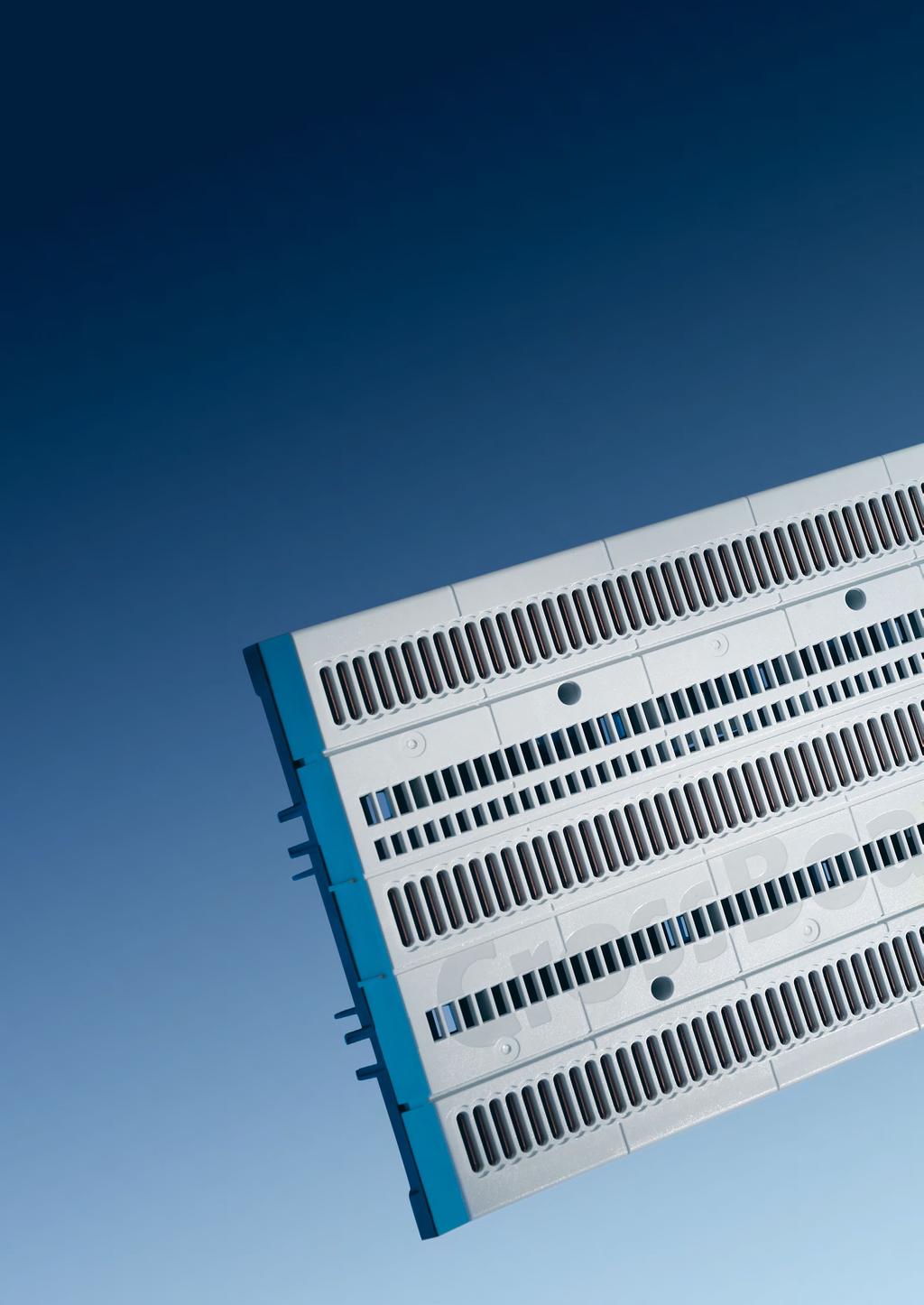
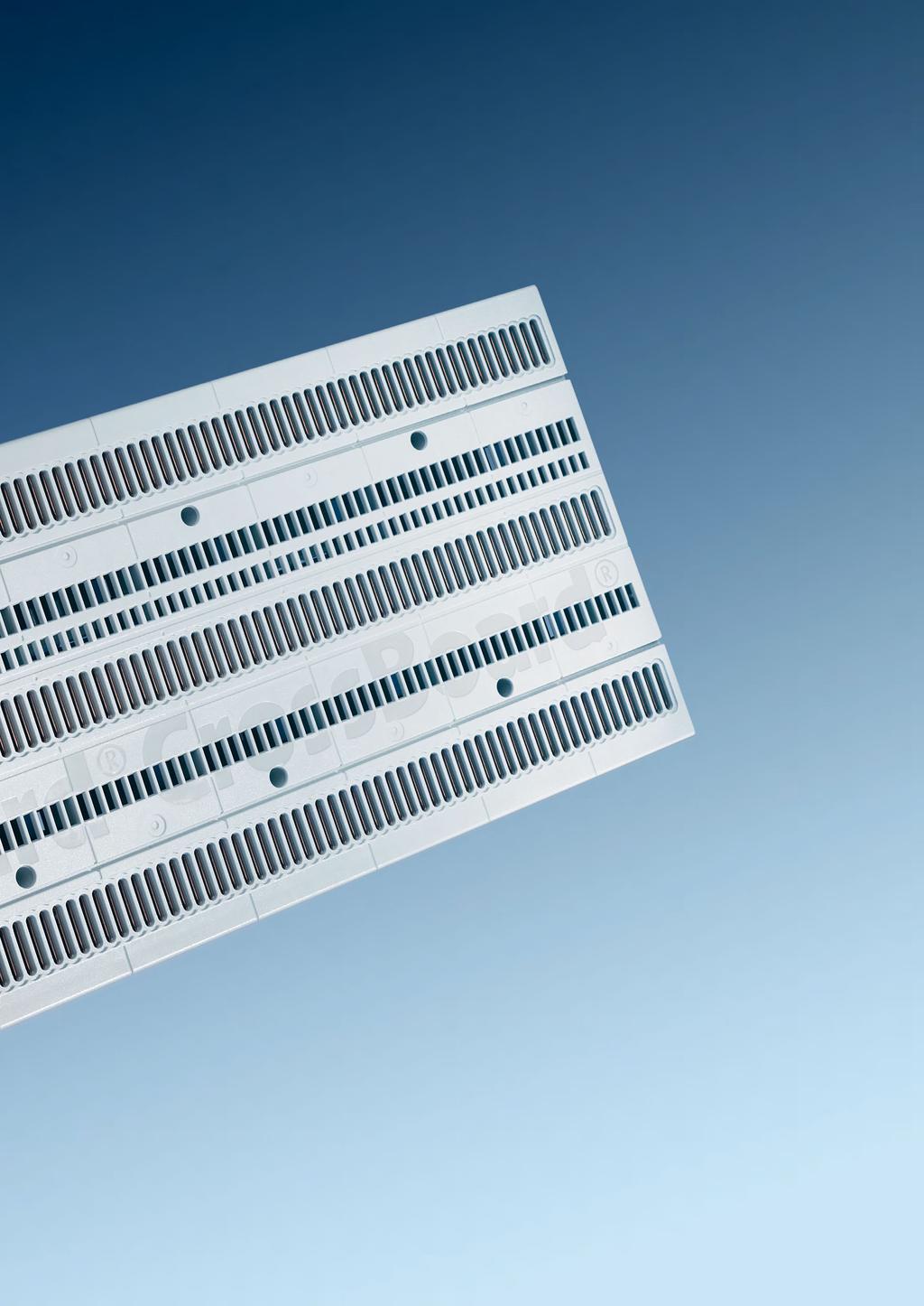
12 CrossBoard TECHNOLOGY CrossBoard


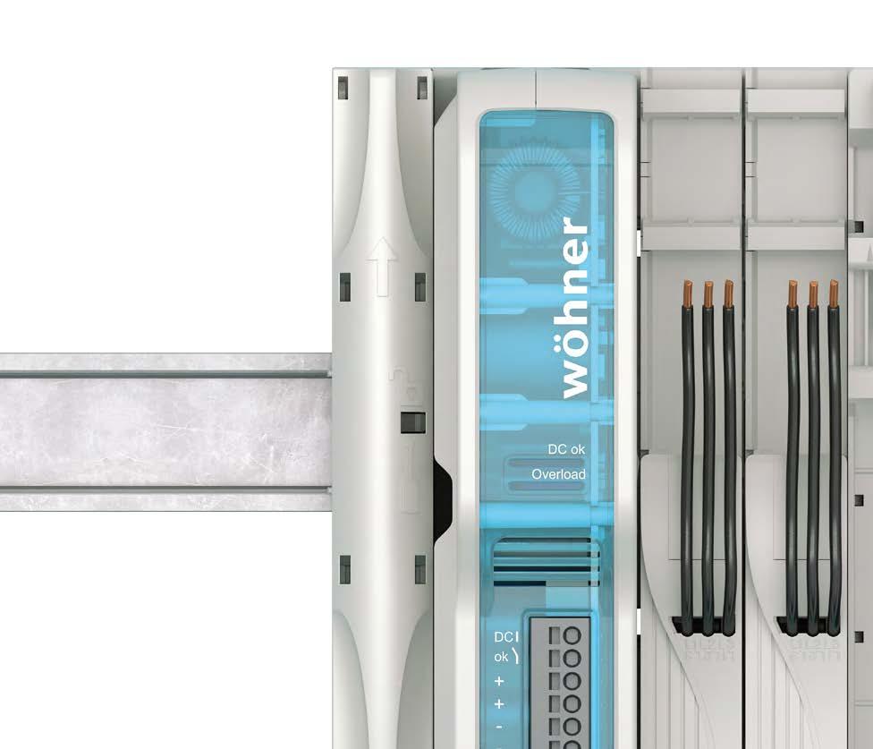
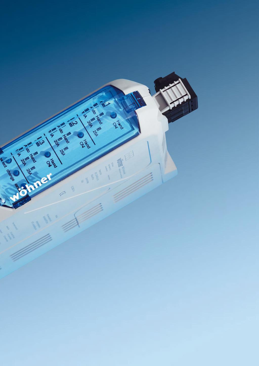
13 CrossBoard 125 A 1 CrossBoard the new basic system Tool-free mounting combined with high safety due to the integrated touch-safe protection make CrossBoard by Wöhner the ideal system solution for power distribution equipment up to 125 A. The user can quickly and easily snap components onto the new base system. CrossBoard is suitable mainly for applications in machine and plant engineering. The modular structure ensures that the systems are clearly structured and, when necessary, easy to change or expand. Motors up to 4 KW can be supplied directly from the CrossBoard using the MOTUS hybrid motor starter. The OMUS hybrid switch with its low power dissipation and high life expectancy is available for resistive loads.
, 600 V AC / 600 V DC (UL) UL listed CRITO CrossBoard Connection")

14 CrossBoard 225 Connection and mounting platform for all components. Rated current: 125 A Equipment width: 225 mm Height: 160 mm Short-circuit capacity: Ipk = 25 ka Rated voltage 690 V AC / 600 V DC (IEC), 600 V AC / 600 V DC (UL) UL listed CRITO CrossBoard Connection module for CrossBoard. Particularly safe, simple and comfortable mounting. With spring terminal. Rated current: max. 80 A Equipment width: 22.5 mm Connection area: mm² Snap lock technology for toolfree conductor connection UL listed EQUES CrossBoard Slim The EQUES universal adapter in a width of 22.5 mm can be used for mounting measuring and monitoring relays. Rated current: 16 A Conductor cross-section: 2.5 mm² For 1 to 3 pole devices Fuse for Class CC fuses up to max. 16 A UL listed OMUS CrossBoard MOTUS CrossBoard Hybrid switch for switching resisitive loads. The hybrid switching technology minimises power dissipation. Up to 25 A continuous current Equipment width: 36 mm 4 integrated functions: Energy supply, fuse protection, monitoring and switching Switchable in a choice of 3-pole or 1-pole UL listed Hybrid motor starter with additional features. Integrated functions: Direct and reversing starter, overload protection and emergency stop. Space requirement and wiring cost significantly reduced. 3 design versions: up to 0.6 A, up to 2.4 A and up to 9 A Equipment width: 22.5 mm Hybrid switching technology Up to 30 mil. switching cycles UL listed


15 CrossBoard 125 A 1 CrossBoard 405 Connection and mounting platform for all components. Rated current: 125 A Equipment width: 405 mm Height: 160 mm Short-circuit capacity: Ipk = 25 ka Rated voltage 690 V AC / 600 V DC (IEC), 600 V AC / 600 V DC (UL) UL listed EQUES CrossBoard Basic Busbar adapter for mounting motor protection devices. With a fixed mounting rail. Rated current: up to 32 A Equipment width: 45 mm Connection cables: 2.5 mm², 6 mm² UL listed EQUES CrossBoard Comfort In order to simply mount motor starter combinations of different manufacturers, the EQUES CrossBoard Comfort adapter is available. Rated current: up to 45 A Equipment width: 45 mm Moveable mounting rail Connection cables: 2.5 mm², 4 mm², 6 mm² or 10 mm² UL listed BROOME10 CrossBoard Power supply for direct connection on the CrossBoard Equipment width: 45 mm Nominal output current up to 10 A Up to 4 devices cascadable (40 A) Integrated fuse protection

16 1 1 CrossBoard basic system 3-pole up to 125 A CrossBoard modular power distribution system, with touch-safe protection and CrossLink Technology Type Rated Width Height current CrossBoard A CrossBoard CRITO CrossBoard connection module, 3-pole, with SnapLock connection technology, cover cap and CrossLink Technology Type For use up Width Height to max. with integrated spring terminals mm², AWG A BROOME10 CrossBoard, with touch-safe protection with Crosslink Technology Type Nominal output current Width Height 24V, with push-in terminals 10 A Parallel connection for increased current and series connection for increased voltage possible Available from 1st quarter 2018 New product UL certificate
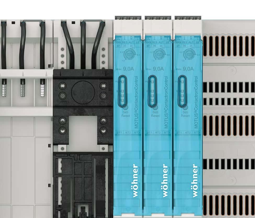
17 CrossBoard 125 A 1 2 MOTUS CrossBoard and OMUS CrossBoard Hybrid switch for switching of inductive and resistive loads MOTUS CrossBoard hybrid motor starter, 3-pole, with reversing function and CrossLink Technology Type Rated current Width Height electronic unit A direct and reversing starter 0.6 A electronic unit A direct and reversing starter 2.4 A electronic unit A direct and reversing starter 9 A Replacement fuses, for MOTUS CrossBoard Type fuse 16 A for version 0.6 A and 2.4 A fuse 20 A for version 9 A fuse 30 A for version 9 A for motors with heavy-duty starting OMUS CrossBoard hybrid switch, 3 or 1-pole switchable, for resistive loads, with CrossLink Technology Type Rated Width Height current electronic unit, 25 A (IEC) 25 A electronic unit, 20 A (UL) 20 A Supplied with both load and control plug Replacement components, for OMUS CrossBoard Type 3-pole plug with spring terminals pole plug with screw terminals pole control plug with spring terminals Replacement fuses, for OMUS CrossBoard cylindr. fuse link 32 A cylindr. fuse link 30 A, time delay New product UL certificate
18 1 3 EQUES CrossBoard Adapter 16 A 45 A 3-pole Adapter Slim, 16 A, with fuse carrier, with CrossLink Technology, with leads AWG 14 (2.5 mm²) Type Rated current Width Height 1 fixed mounting rail, with fuse carrier 10x38 / Class CC 16 A Adapter Basic, with CrossLink Technology Type Rated current Width Height 1 fixed mounting rail, with leads AWG 14 (2.5 mm²) 16 A fixed mounting rail, with leads AWG 10 (6 mm²) 32 A Adapter Comfort, with CrossLink Technology Type Rated current Width Height 1 adjustable mounting rail, with leads AWG 14 (2.5 mm²) 16 A adjustable mounting rail, with leads 160 mm long AWG A (2.5 mm²), for devices with spring terminal technology 1 adjustable mounting rail, with leads AWG 14 (2.5 mm²) 25 A adjustable mounting rail, with leads AWG 10 (6 mm²) 32 A adjustable mounting rail, with leads 160 mm long AWG 10 (6 32 A mm²), for devices with spring terminal technology 1 adjustable mounting rail, with leads AWG 8 (10 mm²) 45 A Article and available from 1st quarter 2018 Extention components, for Adapter Comfort Article Type Width extension module for direct starters 40 mm extension extension set for reversing starters Accessories, for Adapter Comfort mounting rail 45 mm positioning piece for Siemens S00 and S positioning piece for Eaton PKZ New product Accessories 7.7; 7.8; 7.9 UL certificate
19 CrossBoard 125 A
20 30Compact 200 A / 360 A
21 2

22 BUSBAR SYSTEM TECHNOLOGY 30Compact


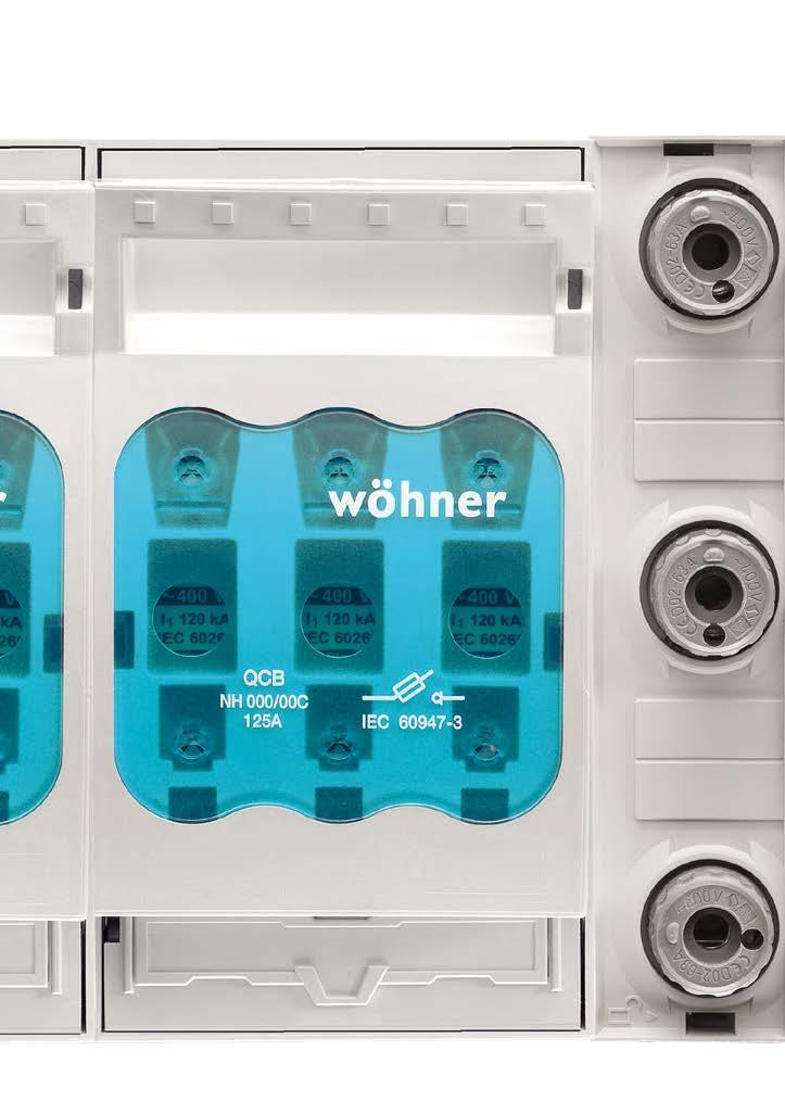
23 30Compact 200 A / 360 A 2 Compact busbar system for control systems and power distribution up to 360 A The 30Compact busbar system is the ideal solution for distribution boards with a rated current up to 360 A. With an installation height of just 160 mm a particularly compact system can be realized. The 30Compact busbar system offers a clear space advantage compared to the 60Classic busbar system. Especially with smaller systems and their lower power requirements, valuable space can be saved within the cabinet. For such applications the 30Compact is the ideal system.
 busbar With end cover UL listed, with 3-pole installation CRITO 30Compact Connection module with spring terminals for 30Compact for")

24 Busbar support 30Compact Busbar support for easy and safe installation. 3-pole with 60 mm distance between busbar centres, also for use in UL applications. 3 to 5 pole busbar support For 12 5 and mm (3-pole only) busbar With end cover UL listed, with 3-pole installation CRITO 30Compact Connection module with spring terminals for 30Compact for particularly simple and comfortable mounting. Rated current: max. 80 A Equipment width: 20 mm Connection area: mm² Spring loaded technology for tool-free conductor connection UL listed QUADRON 30Compact NH fuse-switch disconnector Compact equipment practice, for NH 000 fuses. CrossLink Technology: Toolfree mounting, spring-loaded contact and offering a particularly safe connection, changing the direction of outgoing connection is easy and safe. Rated current: up to 125 A Equipment width: 90 mm Connection area: mm² EQUES 30Compact In order to mount motor starter combinations of different manufacturers, the EQUES 30Compact busbar adapter is available. Rated current: 32 or 63 A Equipment width: 45 or 54 mm Moveable mounting rail Connection cables: 6 or 10 mm² Side-mounted module 9 mm wide UL listed


25 30Compact 200 A / 360 A 2 CRITO 30Compact Connection terminal plates. Comfortable terminals for drillfree connection technology. Integrated touch-safe protection, Compliance with air and creepage distances for UL. Rated current: up to 480 A Equipment width: 54 or 90 mm Connection area: mm² Flexible copper bars UL listed CUSTO 30Compact Bus mounting fuse base for D02 fuses Rated current: up to 63 A Equipment width: 36 mm Connection area: mm² MOTUS 30Compact Hybrid motor starter with additional features. Integrated functions: Direct and reversing starter, overload protection and emergency stop. Space requirement and wiring cost significantly reduced. 3 design versions: up to 0.6 A, up to 2.4 A and up to 9 A Equipment width: 22.5 mm Hybrid switching technology Up to 30 mil. switching cycles UL listed OMUS 30Compact Hybrid switch for switching resistive loads. By means of Hybrid switch technology the power dissipation is minimised Up to 25 A continuous current Equipment width: 36 mm 4 integrated functions: Energy supply, fuse protection, monitoring and switching Switchable in a choice of 3-pole or 1-pole UL listed

26 2 1 30Compact busbar system 3-pole systems, system height 160 mm Busbar support, with end cover For busbar for busbar 3-pole 12 x 5 and 12 x UL spacer Type suitable for Copper busbars, flat busbars, tin-plated Type Length Crosssection mm² 12 x x For current carrying capacity of the busbars visit partial lengths on request Cover section, for 3-pole busbar systems 0.70 m long Mount for cover sections, for 3-pole busbar systems for Busbar cover, 1 m long for 12 x 5 busbar, 1 m long for x 5 busbar, 1 m long for x 10 busbar, 1 m long Zubehör 2.5 UL certificate
27 30Compact 200 A / 360 A 2 2 CRITO 30Compact connection technology 1-pole and 3-pole, system height 160 mm Universal connection terminal, 1.5 to 120 mm² For busbar Connection min. max. Terminal space W x H For use up to max. flat busbars 5 mm mm², AWG ,5 x 7,5 180 A mm², AWG ,5 x A mm², AWG 14-2/0 14 x A mm², AWG 4 - MCM x A flat busbars 10 mm mm², AWG ,5 x 7,5 180 A mm², AWG ,5 x A flat busbars 10 mm and section busbars mm², AWG 14-2/0 14 x A mm², AWG 4 - MCM x A Cover cap for universal connection terminal terminal cover, for and Brace terminal, up to 150 mm², for round conductors For busbar Connection min. - max. Terminal space W x H 12, 15, 20 x 5, 10 * mm², AWG 2 - MCM 300, lam. Cu. 15x x10 * When using aluminium conductors, observe the maintenance instructions (see 8.2) For use up to max. Connection module, 3-pole, for 12 x 5 and 12 x 10 busbars, with spring terminals, with cover cap Connection Width For use up to max. 20 x A with integrated spring terminals mm², AWG A Connection terminal plate, 3-pole, for 12 x 5 and 12 x 10 busbars, with cover cap 6-50 mm², AWG 10-2/0, lam. Cu. 7x4... 9x A mm², AWG 2 - MCM 300, lam. Cu. 15x x A Busbar connecting terminal, for identical busbars For busbar System spacing Width For use up to max. 12, 15, 20 x 5, A , 15, 20 x 5, A pieces required for a 3-pole connection, use and as cover New product UL certificate
28 2 3 EQUES 30Compact MOTUS 30Compact and OMUS 30Compact Busbar adapter and hybrid switch for switching of inductive and resistive loads, system height 160 mm Busbar adapter, 16 A, with fuse carrier, with removable top section, with leads AWG 14 (2.5 mm²) Type Width Height 1 fixed mounting rail, with fuse carrier 10x38 / Class CC Busbar adapter, 32 A, with leads AWG 10 (6 mm²) 1 adjustable mounting rail Busbar adapter, 63 A, with leads AWG 8 (10 mm²) 1 adjustable mounting rail Busbar adapter, 160 A, connection to system at the top for Siemens 3VA10, 11 and 3VT Side-mounted module, for busbar adapters 32 A to 63 A for and MOTUS 30Compact hybrid motor starter, 3-pole, with reversing function and CrossLink Technology A direct and reversing starter A direct and reversing starter A direct and reversing starter Spare parts, for MOTUS 30Compact electronic unit A direct and reversing starter electronic unit A direct and reversing starter electronic unit A direct and reversing starter busbar adapter for MOTUS 30Compact fuse 16 A for version 0.6 A and 2.4 A fuse 20 A for version 9 A fuse 30 A for version 9 A for motors with heavy-duty starting OMUS 30Compact hybrid switch, 3 or 1-pole switchable, for resistive loads, with CrossLink Technology Type Width Height 25 A (IEC) A (UL) Spare parts, for OMUS 30Compact electronic unit, 25 A (IEC) electronic unit, 20 A (UL) busbar adapter for OMUS 30Compact pole plug with spring terminals pole plug with screw terminals pole control plug with spring terminals Spare parts fuses, for OMUS 30Compact cylindr. fuse link 32 A cylindr. fuse link 30 A, time delay New product Accessories 7.7; 7.8; 7.9 UL certificate
29 30Compact 200 A / 360 A 2 4 CUSTO 30Compact and QUADRON 30Compact 3-pole fuse base and fuse-switch-disconnector, system height 160 mm D0 bus-mounting fuse base, with touch-safe protection Type Width Height E 18 / 63 A XX,YY NH bus-mounting fuse base, 000, 3-pole Type Rated current Width Height box terminal mm², outgoing terminal bottom/top 125 A XX,YY Accessories for NH bases Type grip lug cover XX,YY NH bus-mounting fuse-switch-disconnector, 000, 3-pole Type Rated current connection box terminal mm², outgoing terminal bottom/top Width Height 125 A XX,YY Accessories for fuse-switch-disconnectors Type changeover 250 V AC/5 A, 30 V DC/4 A XX,YY Zubehör 7.7; 7.8; 7.11 UL certificate
30 2 5 30Compact busbar system 5-pole (N/PE) 5-pole systems, system height 160 mm Intermediate busbar brace, 2 mm wide Type to increase the mechanical strength Busbar support, with end cover for busbars 5-pole 12 x 5 and 12 x 10, N + PE 12 x Copper busbars, flat busbars, tin-plated busbar 12 x For current carrying capacity of the busbars visit Cover section, for 3 to 5-pole busbar systems 700 x Mount for cover section, for 3 to 5-pole busbar systems for Base plate 700 x Connection set, 10 to 120 mm², with cover cap Type Width Height connection set, 3-pole L1-L2-L connection module N connection module PE connection set, 3-pole L1-L2-L connection module PE + N NH bus-mounting fuse-switch-disconnector, 000, 3-pole Type Rated current connection box terminal mm², outgoing terminal bottom/top * Can only be used in 3-pole systems Width Height * 125 A Busbar adapter, 160 A, 4-pole for Schneider Electric INS 100/125/160, top connection to the system Accessories 7.5 UL certificate
31 30Compact 200 A / 360 A 2 6 EQUES 30Compact busbar adapter 32 A 63 A 1-pole, for miniature circuit breakers, system height 160 mm Busbar adapter, 32 A, 1-pole, connection to system at the top Type Width Height 1 fixed mounting rail Connection adjustable to L1, L2, L3 or N Busbar adapter, 63 A, 1-pole, connection to system at the top 1 fixed mounting rail fixed mounting rail, for Schneider Electric ic60, ic65 and C Connection adjustable to L1, L2, L3 or N Busbar support, without electrical connection 1 fixed mounting rail PE/N adapter module, with terminal 16 mm² module PE module N * * Without their own locking on the busbar system. Must be plugged onto busbar adapter Side-mounted module, for adapters for single pole busbar adapters Accessories Type connector to create multipole adapters * * For 50 device connections
32 60Classic 630 A / 800 A / 2500 A
33 3

34 BUSBAR SYSTEM TECHNOLOGY 60Classic


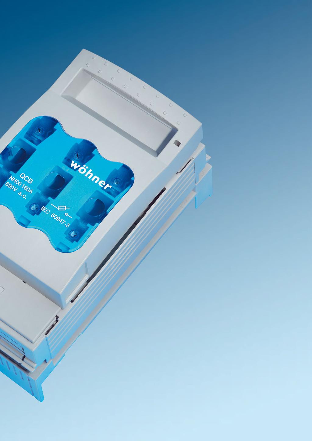
35 60Classic 630 A / 800 A / 2500 A 3 Busbar system with a large selection of components for many applications A busbar centre distance of 60 mm is the standard in most low-voltage distribution applications today. Developed by Wöhner this standard has been implemented in the 60Classic system and has become the most common busbar system in many sectors. Two main reasons for its success: 60Classic is particularly space-saving and provides a huge selection of components. Depending on requirements, busbars of various cross sections can be used; currents up to a maximum of 2500 A are possible.


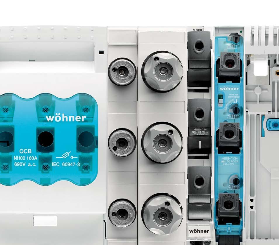
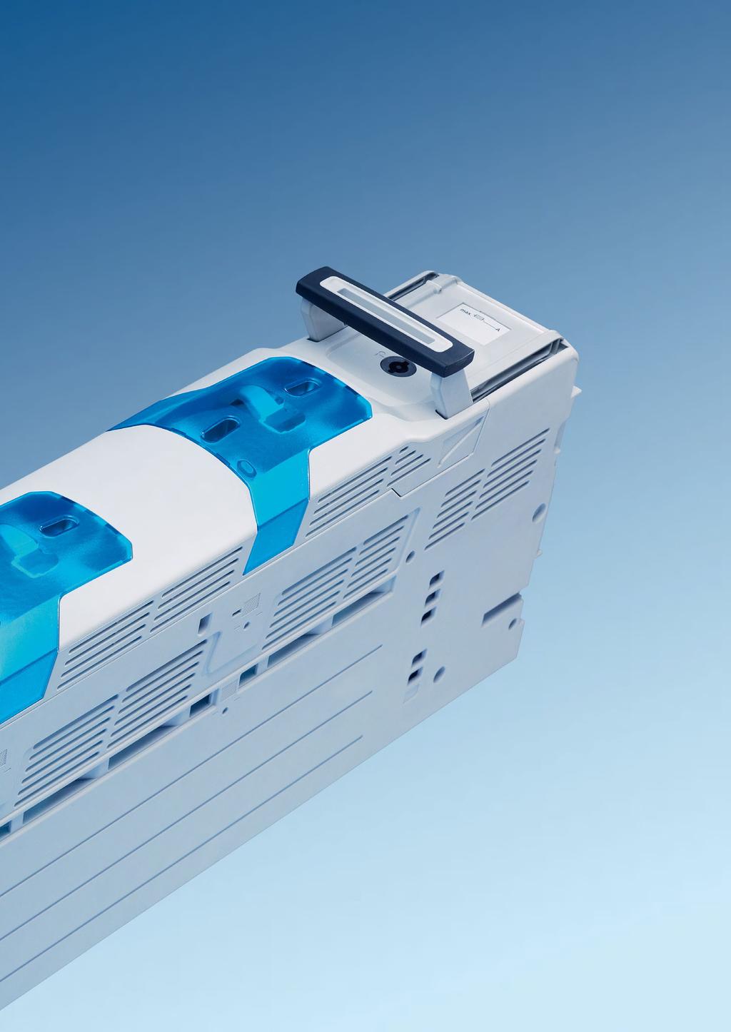
36 Busbar 60Classic 12, 15, 20, 25 and 30 5 and 10 mm Double and triple T section busbar for increased current requirements Tin-plated versions Proven Load current Proven short-circuit capacity UL listed Busbar support 60Classic Busbar support for easy and safe installation of systems with 60 mm distance between busbar centres. 1, 2, 3 and 4-pole versions Adjustable for busbar 12 5 up to mm Versions for double and triple T bars UL listed Versions in connection with spacer or base plate CUSTO 60Classic 3 pole bus-mounting fuse base for D and D0 fuses. Covers also available for double widths Versions with integrated touch-safe protection Rated current: up to 63 A Equipment width: 27 to 57 mm Connection area: mm² / 35 mm² D base option available for gauge ring and screw-in gauge ring SECUR 60Classic PowerLiner D0 bus-mounting switch disconnector with tried and tested drawer-type method was designed for higher requirements. All phase conductors are comfortably guided downwards. Captive fuse carrier for commercial gauge rings Optional side-mounted module, LED display and auxiliary switch 3-pole version QUADRON 60Classic NH bus-mounting fuse-switch disconnector up to 630 A. With CrossLink technology: springloaded contacts offer safe, toolfree mounting, simple change of outgoing conductor direction. For NH 000 to 3 fuse links Versions with fuse monitoring Various accessories for connections and shrouding QUADRON 60Classic Class J bus-mounting fuse base. With CrossLink technology: spring-loaded contacts offer safe, tool-free mounting, simple change of outgoing conductor direction. For class J to 30, 60 and 100 A as well as 200 A and 400 A fuses Integrated fuse adaptor for ease of use UL listed


37 60Classic 630 A / 800 A / 2500 A 3 CRITO 60Classic Connection module for 60Classic. Particularly simple, safe and comfortable mounting. With spring terminal. Rated current: max. 80 A Equipment width: 20 mm Connection area: mm² Spring loaded technology for tool-free conductor connection UL listed CRITO 60Classic Connection technology for many different conductor types up to 300 mm² cross-section and up to 32 mm wide flexible copper bars. Rated current: up to 800 A Connection area from 6 to 300 mm² Equipment width: 54, 81, 135, 153, 204 mm Flexible copper bars UL listed SECUR 60Classic EasyLiner Bus-mounting switch disconnectors for D0 fuses with Snap- Lock Technology. Flat design, especially suitable for use in distribution boards. Captive fuse carrier for commercial gauge rings Optional side-mounted module, LED indicator and auxiliary switch 3-pole version Lockable AMBUS 60Classic Bus-mounting fuse holder for class CC fuses or to 32 A, snap-on mounting on busbars, easy outgoing conductor connection with spring terminals Equipment width: 27 mm 2, 3 and 4 pole versions Versions with LED indicator 1 pole version for photovoltaic applications UL listed QUADRON 60Classic Speed The switch disconnector with NH fuses is the highlight. Its snap-action switch mechanism enables safe, operatorindependent switching. CrossLink technology: Snap-on mounting in the 60Classic system Double interruption Lockable in off-position Versions with rotary drive or fuse monitoring EQUES 60Classic The EQUES busbar adapters are available for simple mounting of motor starter combinations from various manufacturers. Rated current: up to 80 A Equipment width; from 45 to 90 mm Moveable mounting rail Connection cables 2.5 to 10 mm², terminals to 16 mm² Versions with CrossLink technology UL listed

38 EQUES 60Classic Busbars adapter for circuit breakers up to 630 A 3 and 4-pole versions Versions for all commercial available switching devices Size aligned to circuit breaker Simple and comfortable mounting Integrated connection for the respective switching device UL listed MOTUS 60Classic Hybrid motor starter with additional features. Integrated functions: Direct and reversing starter, over load protection and emergency stop. Space requirement and wiring cost significantly reduced. 3 design versions: up to 0.6 A, up to 2.4 A and up to 9 A Equipment width: 22.5 mm Hybrid switching technology Up to 30 mil. switching cycles UL listed


39 60Classic 630 A / 800 A / 2500 A 3 OMUS 60Classic Hybrid switch for switching resistive loads. The hybrid switching technology minimises power dissipation. Up to 25 A continuous current Equipment width: 36 mm 4 integrated functions: Energy supply, fuse protection, monitoring and switching Switchable in a choice of 3-pole or 1-pole UL listed CRITO Brace terminals for round or flat conductors. Simple and convenient connection of conductors and busbars. Conductor connection possible from above and below Looping possible For round conductors from 35 to 300 mm² For flat conductors up to 100 mm wide For UL listed flat conductors

40 3 1 60Classic busbar system 1, 2, 3, 4-pole systems, system height 200 mm Universal Busbar support, without end cover Type Busbar 2-pole with internal screw holes 12, 20, 30 x 5, pole with internal screw holes 12, 15, 20, 25, 30 x 5, pole with additional external screw holes pole with internal screw holes UL busbar support, without end cover 3-pole, with internal screw holes 12, 20, 30 x 5, pole, with internal screw holes UL spacer, for UL busbar support suitable for suitable for Base plate, for UL busbar supports 01508, 01231, x x PE/N busbar support, incl. PE and N labels Type Busbar 2-pole, indiv. mountable * 12, 15, 20, 25, 30 x 5, pole, indiv. mountable 12, 20, 30 x 5, * Stepped busbar Connection busbar support, without end cover Type Busbar with integrated terminals mm² 12, 15, 20, 25, 30 x 5, End cover, for universal busbar supports, to cover the busbar ends Type for busbar support and for busbar support for busbar supports 01484, 01495, 01500, and for busbar supports and Accessories 3.3 UL certificate

41 60Classic 630 A / 800 A / 2500 A Classic busbar system with section busbars 1, 3, 4-pole systems Busbar support, for double-t section, without end cover Type 1-pole, to be attached to and individually mountable pole, with internal screw holes Busbar support, for triple-t section, without end cover 1-pole, to be attached to and individually mountable pole, with internal screw holes Busbar support, for TCC section, without end cover 3-pole, with internal screw holes End cover, for busbar support for section busbars for busbar supports and for busbar supports and for busbar support Accessories 3.3 UL certificate

42 3 3 60Classic busbar system Standard copper busbars and section busbars Copper busbars, flat busbars, tin-plated Type Length Crosssection mm² busbar 12 x busbar 15 x busbar 20 x busbar 25 x busbar 30 x busbar 12 x busbar 20 x busbar 20 x busbar 30 x busbar 30 x For current carrying capacity of the busbars visit partial lengths on request Section copper busbar, tin-plated Type Length Crosssection mm² double-t section busbar 500 mm² double-t section busbar 500 mm² double-t section busbar 720 mm² double-t section busbar 720 mm² triple-t section busbar 1140 mm² triple-t section busbar 1140 mm² TCC section busbar 1600 mm² For current carrying capacity of the busbars visit partial lengths on request Section copper busbar, plain double-t section busbar 500 mm² double-t section busbar 500 mm² double-t section busbar 720 mm² double-t section busbar 720 mm² For current carrying capacity of the busbars visit partial lengths on request UL certificate
43 60Classic 630 A / 800 A / 2500 A Classic covering system 1, 3 and 4-pole versions Busbar cover, for 1-pole busbars Type PG Part no. for x 5 busbar, 1 m long for x 10 busbar, 1 m long for double-t and triple-t section, 1m long for 12 x 5 busbar, 1 m long For individual busbars Cover section, for 3-pole busbar systems 700 x Mount, for cover sections, for 3-pole busbar systems depth 32 mm, for depth 107 mm, for 01025, 01236, 01237, Snaps directly onto busbars 12, 15, 20, 25, 30 x 5, 10, double-t and triple-t section Holder set, for cover sections for 3-pole busbar systems set consisting of left and right holder, for covers 01554, and Cover section, for holder set, for 3-pole busbar systems front mounted, 1.10 m long, for holder top / bottom, 1.10 m long, for holders or top / bottom, slotted, 1.10 m long, for holders or Snaps directly onto busbars 12, 15, 20, 25, 30 x 5, 10, double-t and triple-t section Holder set, for cover sections for 4-pole busbar systems set consisting of left and right holder, for covers 01599, and Cover section, for holder set, for 4-pole busbar systems front mounted, 1.10 m long, for holder top / bottom, 1.10 m long, for holders or top / bottom, slotted, 1.10 m long, for holders or Compartment section, for adjusting the installation depth for double-t and triple-t section busbar systems 48 mm deep, 2.40 m long mm deep, 2.40 m long mm deep, 2.40 m long UL certificate
44 3 5 CRITO 60Classic connection technology 3 and 4-pole versions Connection busbar support, 3-pole, for 12, 15, 20, 25, 30 x 5, 10 busbars, with cover cap Type For use up to max. Width with integrated terminals mm² 80 A Connection module, 3-pole, for 12, 15, 20, 25, 30 x 5, 10 busbars, with spring terminals and cover cap with integrated spring terminals mm², AWG A Connection terminal plate, 3-pole, for 12 x 5 30 x 10 and section busbars, with cover cap 6-50 mm², AWG 10-2/0, lam. Cu. 7x4... 9x A mm², AWG 2 - MCM 250, lam. Cu. 12x x A Accessory, for single terminal covers Type for terminal plate for terminal plate Connection terminal plate, 3-pole, for 20 x 5 30 x 10 and double-t and section busbars, with cover cap Type For use up Width to max mm² * 460 A mm² * 560 A lam. Cu. 20x x15 ** 800 A * When using aluminium conductors, observe the maintenance instructions (see 8.2) ** Observe the minimum terminal space (see specifications at Connection set, 3-pole, for 20 x 5 30 x 10 and double-t and section busbars, without cover cap mm², AWG 3/0 - MCM 600 * 560 A lam. Cu. 20x x A * When using aluminium conductors, observe the maintenance instructions (see 8.2) Connection set, 4-pole, for 20 x 5 30 x 10 and double-t and section busbars, without cover cap mm², AWG 3/0 - MCM 600 * 560 A lam. Cu. 20x x A * When using aluminium conductors, observe the maintenance instructions (see 8.2) Accessories 7.12; 7.13 UL certificate

45 60Classic 630 A / 800 A / 2500 A 3 6 CRITO conductor connection terminals 1-pole and covers Universal connectionr terminal, 1.5 mm 2 to 120 mm 2 For busbar Connection min. - max. Terminal space W x H For use up to max. flat busbars 5 mm mm², AWG ,5 x 7,5 180 A XX,YY mm², AWG ,5 x A XX,YY mm², AWG 14-2/0 14 x A XX,YY mm², AWG 4 - MCM x A XX,YY flat busbars 10 mm mm², AWG ,5 x 7,5 180 A XX,YY mm², AWG ,5 x A XX,YY flat busbars 10 mm and section busbars mm², AWG 14-2/0 14 x A XX,YY mm², AWG 4 - MCM x A XX,YY Cover cap for universal connection terminal Type terminal cover, for and XX,YY Brace terminal, up to 300 mm², for round conductors For busbar Connection For use up to max. 12, 15, 20 x 5, 10 * mm², AWG 2 - MCM 300, lam. Cu. 480 A XX,YY x x10 20, 25, 30 x 5, 10 and section * Cu / Al mm² 500 A XX,YY busbars 20, 25, 30 x 5, 10 and section busbars * Cu / Al mm² 600 A XX,YY * When using aluminium conductors, observe the maintenance instructions (see 8.2) Brace terminal, 30 to 105 mm wide, for flat conductors For busbar Terminal space W x H 20, 25, 30 x 5, 10 and section busbars End feed Centre feed 30 x A 750 A XX,YY x A 800 A XX,YY x 10 and section busbars 55 x A 2000 A XX,YY x A 2000 A XX,YY x A 2800 A XX,YY Cover cap, 3-pole, can also be used as a reserve section cover For busbar W x H X D 12, 15, 20, 25, 30 x 5, 10 and section busbars 54 x 200 x XX,YY , 15, 20, 25, 30 x 5, 10 and section busbars 84 x 200 x XX,YY , 25, 30 x 5, 10 and section busbars 135 x 200 x XX,YY , 15, 20, 25, 30 x 5, 10 and section busbars 180 x 200 x XX,YY , 15, 20, 25, 30 x 5, 10 and section busbars 228 x 200 x XX,YY , 15, 20, 25, 30 x 5, 10 and section busbars 250 x 200 x XX,YY , 25, 30 x 5, 10 and section busbars 270 x 200 x XX,YY Cover cap, 4-pole, can also be used as a reserve section cover 12, 15, 20, 25, 30 x 5, 10 and section busbars 228 x 260 x XX,YY New product Accessories 7.12; 7.13 UL certificate
46 3 7 CRITO conductor connection terminals 1-pole and busbar connecting terminals Screw-type terminal, attachable, for DIN cable lugs Type Terminal space W x H For use up to max. flat busbars 5 mm M5 x A M8 x A M10 x A flat busbars 10 mm M5 x A , 15, 20, 25, 30 x 10 and section busbars M8 x A M10 x A Busbar connector, for connection of flat busbars and laminated copper bar Type Terminal space W x H max. height connection of busbar 25 wide with lam. Cu 20 wide 25 x connection of busbar 30 wide with lam. Cu 20 wide 30 x connection of busbar 30 wide with lam. Cu 30 wide 30 x connection of busbar 35 wide with lam. Cu 30 wide 35 x connection of busbar 40 wide with lam. Cu 20 wide 40 x connection of busbar 40 wide with lam. Cu 32 wide 40 x Busbar connection terminals, in longitudinal direction with wedge clamp terminal Busbar Round conductor min max Flat conductor W x H 20 x 5, x x 5, x Busbar connecting terminal, in longitudinal direction with brace terminal, for laminated copper bar the terminal is able to connect flexible copper 32x10 in longitudinal direction 32 x Accessories 7.12; 7.13 UL certificate
47 60Classic 630 A / 800 A / 2500 A 3 8 CRITO conductor connection terminals 1-pole profile terminals for flat conductors Profile terminal, for double-t section busbars Connection cross-section End feed Centre feed Terminal space W x H mm² 1600 A 1600 A 41 x mm² 1600 A 1600 A 51 x mm² 1600 A 1600 A 64 x mm² 1600 A 2000 A 51 x mm² 1600 A 2000 A 64 x mm² 1600 A 2500 A 81 x mm² 1600 A 2800 A 101 x For the connection of flat busbars and flexible copper busbars Profile terminal, for triple-t section busbars mm² 1600 A 1600 A 41 x mm² 2000 A 2500 A 64 x mm² 2500 A 3200 A 101 x For the connection of flat busbars and flexible copper busbars Brace terminal, for busbars 30 x 10 mm and section busbars mm² 1600 A 2000 A 55 x mm² 1600 A 2000 A 68 x mm² 1600 A 2800 A 105 x For the connection of flat busbars and flexible copper busbars Connection terminal Busbar For use up to max. Connection 30 x 10 and section busbars 630 A mm² x 10 and section busbars 1250 A 40 x Flexible copper busbars, plain Cu., insulated, length 2 m Dimensions (number of laminates x width x thickness) Rated current at 30 K Rated current at 50 K Cross-section mm² 10 x 40 x A 1053 A x 50 x A 1244 A x 63 x A 1481 A x 80 x A 1777 A x 100 x A 2110 A You will find more flexible copper busbars in the accessories section Accessories 7.12; 7.13 UL certificate

48 3 9 CRITO longitudinal busbar connectors for flat conductors and section busbars Busbar connecting terminal, for same- busbar For busbar Length System spacing For use up to max. 12, 15, 20 x 5, mm 520 A mm 520 A , 25, 30 x 5, mm 630 A mm 630 A mm 630 A mm 630 A double-t section mm 1600 A mm 1600 A mm 1600 A mm 1600 A triple-t section mm 2500 A A pieces are required for a 3-pole connection, use or as well as as covers (see 3.4). For a UL-compliant design of the longitudinal busbar connector, one of the UL separation blocks described below must be used UL separator set, 3-pole, for longitudinal busbar connectors Type Width for longitudinal connecting terminals 01990, 01823, * for longitudinal connecting terminals 01141, 01145, * for longitudinal connecting terminals 01886, 01829, * The depth gauge must be tailored to fit Connection set, 3-pole, for section busbars For busbar Type For use up to max. double-t section * 150 mm, flexible longitudinal connection 1600 A double-t section * 130 mm, flexible corner connection triple-t section * 200 mm, flexible longitudinal connection 2500 A * Supplied as a 3-pole connection set Accessories 3.4 UL certificate

49 60Classic 630 A / 800 A / 2500 A 3 10 EQUES 60Classic with CrossLink busbar adapter 16 A 45 A with removable top section with CrossLink interface. The base is touch-protected and remains on the busbar system Busbar adapter, 16 A, with removable top section, with lead AWG 14 (2.5 mm²) Type Width Height for direct starter Allen-Bradley 140M-RC2E, Eaton PKZM0, Siemens S00, Schneider Electric GV2 with spring terminals Busbar adapter, 16 A, with fuse holder, with removable top section, with lead AWG 12 (4 mm 2 ) 1 fixed mounting rail, with fuse carrier 10x38 / Class CC Busbar adapter, 16 A, with removable top section, with lead AWG 12 (4 mm 2 ) 2 adjustable mounting rails adjustable mounting rails Busbar adapter, 32 A, with removable top section, with lead AWG 10 (6 mm²) 2 adjustable mounting rails adjustable mounting rails Busbar adapter, 45 A, with removable top section, with lead AWG 8 (10 mm²) 2 adjustable mounting rails adjustable mounting rails Busbar adapter, with removable top section, without electrical connection 2 adjustable mounting rails adjustable mounting rails adjustable mounting rails adjustable mounting rails Side-mounted module, for CrossLink busbar adapters attachable to both sides Accessory, for CrossLink busbar adapters Type mounting rail 45 mm mounting rail 54 mm mounting rail 63 mm mounting rail 72 mm mounting rail 81 mm mounting rail end stop connecting element, universal pole connector, with support, 250 V pole connector, with support, 250 V micro switch for CrossLink adapter All devices can be mounted directly on busbars 12, 15, 20, 25, 30 x 5, 10 and section busbars UL certificate

50 3 11 EQUES 60Classic busbar adapter 25 A 80 A Universal version Busbar adapter, 25 A, with leads AWG 12 (4 mm 2 ) Type Width Height 1 adjustable mounting rail adjustable mounting rails adjustable mounting rails adjustable mounting rails Busbar adapter, 25 A, without leads, with screw terminals 6 mm² from rear 2 adjustable mounting rails UL terminal cap for busbar adapters and Busbar adapter, 32 A, with leads AWG 10 (6 mm 2 ) 1 adjustable mounting rail adjustable mounting rail adjustable mounting rails adjustable mounting rail adjustable mounting rail adjustable mounting rails adjustable mounting rails Busbar adapter, 63 A, with leads AWG 8 (10 mm 2 ) 1 adjustable mounting rail adjustable mounting rails adjustable mounting rail adjustable mounting rail adjustable mounting rails adjustable mounting rails Busbar adapter, 80 A, without leads, with screw terminals 16 mm² from rear 1 adjustable mounting rail adjustable mounting rails adjustable mounting rail adjustable mounting rails UL terminal cap for busbar adapters 32466, 32467, and All devices can be mounted directly on busbars 12, 15, 20, 25, 30 x 5, 10 and section busbars Accessories 3.12 UL certificate

51 60Classic 630 A / 800 A / 2500 A 3 12 EQUES 60Classic busbar adapter 32 A 80 A Universal version Busbar adapter, 32 A, without leads, with spring terminal mm² from front Type Width Height 1 adjustable mounting rail adjustable mounting rails Busbar adapter, 80 A, without leads, with screw terminals mm² from front 1 adjustable mounting rail adjustable mounting rails Busbar support, without electrical connection 2 adjustable mounting rails adjustable mounting rail and 1 positioner for Siemens S adjustable mounting rails adjustable mounting rails adjustable mounting rail and 1 positioner for Siemens S00 and S adjustable mounting rails Side-mounted module, for busbar adapter attachable to both sides PE/N adapter module, with connection terminal 16 mm 2, top and bottom, without leads attachable to busbar adapter to both sides Accessory, for adapter Type mounting rail 45 mm mounting rail 54 mm mounting rail 63 mm mounting rail 72 mm mounting rail 81 mm mounting rail end stop connecting element, universal pole connector, with support, 250 V pole connector, with support, 250 V lead AWG 14 (2.5 mm²), 105 mm long * lead AWG 10 (6 mm²), 130 mm long * lead AWG 4 (25 mm²), 210 mm long * double-lead 2x AWG 10 (2x 6 mm²), 130 / 280 mm long * * Ultrasonic-welded lead ends All devices can be mounted directly on busbars 12, 15, 20, 25, 30 x 5, 10 and section busbars New product UL certificate
 Type Width Height for direct starter Allen-Bradley 140M-RC2E, Eaton PKZM0, Siemens S00, Schneider Electric GV2 with spring terminals for reversing starter Allen-Bradley 140M-RC2E, Eaton")
52 3 13 EQUES 60Classic busbar adapter 16 A 100 A tailored to the products of the switchgear manufacturers Busbar adapter, 16A, with leads AWG 14 (2.5 mm 2 ) Type Width Height for direct starter Allen-Bradley 140M-RC2E, Eaton PKZM0, Siemens S00, Schneider Electric GV2 with spring terminals for reversing starter Allen-Bradley 140M-RC2E, Eaton PKZM0, Siemens S00, Schneider Electric GV2 with spring terminals Busbar adapter, 25 A, with leads AWG 12 (4 mm 2 ) for direct starter Eaton PKZ0/BG for reversing starter Eaton PKZ0/BG for direct starter Siemens S00 with screw connection for direct starter Siemens S00 with spring terminal connection for reversing starter Siemens S00 with screw connection for direct starter Siemens S00 with spring terminal connection Busbar adapter, 32 A, with leads AWG 10 (6 mm 2 ) for direct starter ABB MS116/ for direct starter Eaton PKZ0/BG for reversing starter Eaton PKZ0/BG for direct starter Allen-Bradley 140MC/D for reversing starter Allen-Bradley 140M-C/D for direct starter Schneider Electric GV2-M/P for direct starter Schneider Electric GV2-M/P for direct starter Schneider Electric LUB12/ for reversing starter Schneider Electric LUB12/ for direct starter Siemens S0 with screw connection for direct starter Siemens S0 with spring terminal connection for direct starter Siemens S0 with spring terminal connection for direct starter Siemens 3RA Busbar adapter, 63 A, with leads AWG 8 (10 mm 2 ) for direct starter ABB MS45x, Eaton PKZM4, Siemens S for direct starter Allen-Bradley 140M-F for direct starter ABB MS45x and Eaton PKZ Busbar adapter, 80 A, with leads AWG 4 (25 mm 2 ) for Siemens Sirius circuit breaker frame S2, 200 mm long for Siemens Sirius direct starter frame S2, 260 mm long for Siemens Sirius reversing starter frame S2, 260 mm long for Siemens NGG, HGG, LGG (up to 80 A) Busbar adapter, 100 A, with leads AWG 4 (25 mm 2 ) for ABB circuit breaker MS49x and Siemens Sirius circuit breaker frame S3, 200 mm long All devices can be mounted directly on busbars 12, 15, 20, 25, 30 x 5, 10 and section busbars New product UL certificate

53 60Classic 630 A / 800 A / 2500 A 3 14 EQUES 60Classic busbar adapter 160 A 250 A tailored to the products of the switchgear manufacturers and universal busbar adapters Busbar adapter, 160 A, 3-pole, phase pitch mm Type Rated current Width Height for Siemens 3VA10, 11 and 3VT160, top connection to the 160 A system for Siemens 3VA51 and Siemens NGG, LGG, HGG, top 160 A connection to the system for Eaton NZM1, connection top / bottom 160 A for Allen-Bradley 140U-H, top connection to the system 160 A for ABB T-max T1, XT1, T2, XT2, GE FD160, Schneider El. 160 A NS80, NSX80, top connection to the system for ABB T-max T1, XT1, XT2, Allen-Bradley 140G-G and H, 160 A for circuit breakers with terminals for flexible copper, top connection to system for ABB T-max T1, XT1, XT2, Allen-Bradley 140G-G and H, for circuit breakers with connections for flexible copper, bottom connection to the system 160 A Busbar adapter, 250 A, 3-pole, phase pitch mm, connection to system at the top / bottom for ABB Tmax T4, Siemens 3VM/3VA * 290 A for ABB T-max XT4, Allen-Bradley 140G-J 250 A for Allen-Bradley 140U-J and 140M-J 250 A for Schneider Electric NSX100-NSX250, GV7 250 A for Eaton NZM2-XKR4O and NZM2-XKR4U 250 A for Siemens 3VL1 UL 160 A for Siemens 3VL2, 3VL3 UL 250 A for Siemens 3VT250, OEZ BD A for Siemens 3VA12, 20, 21, 22, 52, 61, A for Terasaki S250-NJ * 250 A * connection to system only at the top Busbar adapter, 250 A, 4-pole, phase pitch mm, connection to system at the top for ABB Tmax T4, Allen-Bradley 140G-K 250 A for ABB XT3/XT4 250 A for Siemens 3VA12, 20, 21, 22, 61, A for Schneider Electric NSX100-NSX A for Eaton NZM2-XKR4O 250 A for Siemens 3VL2, 3VL3 250 A Universal busbar adapter, 200A 250A, 3-pole terminals 70 mm² at top 200 A terminals 70 mm² at bottom 200 A terminals mm² at top 250 A terminals mm² at bottom 250 A Accessory, slide nut, for universal busbar adapters Type for 32168, 32214, 32215, All devices can be mounted directly on busbars 12, 15, 20, 25, 30 x 5, 10 and section busbars New product UL certificate

54 3 15 EQUES 60Classic busbar adapter 630 A tailored to the products of the switchgear manufacturers and universal busbar adapters Busbar adapter, 630 A, 3-pole, phase pitch mm, connection to system at the top / bottom Type Rated current Width Height for ABB T-max T5 and Allen-Bradley 140G-K 580 A for Allen-Bradley 140U-K, 140U-L, 140M-L 600 A for Schneider Electric NS400/630, NSX 400/ A for Eaton NZM3-XKR13O and NZM3-XKR13U 630 A for Siemens 3VL4 400 A for Siemens 3VA23, 24, 63, A for Siemens 3VT630, OEZ BH A Busbar adapter, 630 A, 3-pole, phase pitch 63 mm, connection to system at the top for Siemens 3VL5 580 A Busbar adapter, 650 A, 3-pole, phase pitch 70 mm, connection to system at the top for ABB T-max T6 and Allen-Bradley 140G-M 650 A Busbar adapter, 630 A, 4-pole, phase pitch mm, connection to system at the top for ABB Tmax T5, Allen-Bradley 140G-K 500 A for Schneider Electric NSX400-NSX A for Eaton NZM3-XKR13O 500 A for Siemens 3VA23, 24, 63, A for Siemens 3VL A Universal busbar adapter, 630 A, 3-pole connection screws M12 (top / bottom) 630 A Accessory, metal plate, adjustable for adapter All devices can be mounted directly on busbars 12, 15, 20, 25, 30 x 5, 10 and section busbars New product UL certificate

55 60Classic 630 A / 800 A / 2500 A 3 16 MOTUS 60Classic OMUS 60Classic for switching of inductive and resistive loads MOTUS Classic hybrid motor starter, 3-pole, with reversing function and CrossLink Technology Type Width Height Depth A direct and reversing starter A direct and reversing starter A direct and reversing starter Replacement components, for MOTUS 60Classic Type electronic unit A direct and reversing starter electronic unit A direct and reversing starter electronic unit A direct and reversing starter busbar adapter for MOTUS 60Classic fuse 16 A for version 0.6 A and 2.4 A fuse 20 A for version 9 A fuse 30 A for version 9 A for motors with heavy-duty starting OMUS 60Classic hybrid switch, 3 or 1-pole switchable, for resistive loads, with CrossLink Technology Type Width Height Depth 25 A (IEC) A (UL) Supplied with both load and control plug Replacement components, for OMUS 60Classic Type electronic unit, 25 A (IEC) electronic unit, 20 A (UL) busbar adapter for OMUS 60Classic pole plug with spring terminals pole plug with screw terminals pole control plug with spring terminals Replacement fuses, for OMUS 60Classic cylindr. fuse link 32 A cylindr. fuse link 30 A, time delay All devices can be mounted directly on busbars 12, 15, 20, 25, 30 x 5, 10 and section busbars New product UL certificate

56 3 17 CUSTO 60Classic D bus-mounting fuse base 3-pole DII and DIII fuse holder D bus-mounting fuse base with touch-safe protection incl. strip cover, for gauge rings Type Width Height E 27 / 3P E 33 / 3P D bus-mounting fuse base with touch-safe protection incl. strip cover, for screw-in gauge rings E 27 / 3P E 33 / 3P D bus-mounting fuse base without strip cover, for gauge rings E 27 / 3P E 33 / 3P D bus-mounting fuse base without strip cover, for screw-in gauge rings E 27 / 3P E 33 / 3P D strip cover Type Width Height E E E E Touch-safe protection, for all strip covers lateral attachable All devices can be mounted directly on busbars 12, 15, 20, 25, 30 x 5, 10 and section busbars Accessories 7.3; 7.4
 104 1 75.")
57 60Classic 630 A / 800 A / 2500 A 3 18 SECUR 60Classic CUSTO 60Classic 3-pole switch disconnector and D0 fuse holder Bus-mounting switch disconnector with fuses, SECUR 60Classic PowerLiner, tall version, 3-pole, 3-pole / 1-pole switching Type Rated Rated Utilization Depth current voltage category for fuse links D01 and D02 * 63 A 400 V AC-23A (400 V) for fuses 10x38 * 32 A 690 V AC-23A (400 V) AC-22A (690 V) * For continuous loads above 35 A the use of side-mounted module is recommended; fuse links not included Bus-mounting switch disconnector with fuses, SECUR 60Classic PowerLiner, tall version, 3-pole, 1-pole switching for D01 and D02 fuses, with LED * 63 A 400 V AC-23A (400 V) * For continuous loads above 35 A the use of side-mounted module is recommended; fuse links not included Accessory for SECUR 60Classic PowerLiner Type pilot switch side-mounted module reducer D02 for D01 fuses 2-16 A D0 bus-mounting fuse base, CUSTO 60Classic, touch-safe protection incl. strip cover Type Width Height E 18 / 63 A * E 18 / 63 A * The 36 mm-wide version allows optimal cable routing and heat removal D0 bus-mounting fuse base, CUSTO 60Classic, without strip cover E 18 / 3P * E 18 / 3P * The 36 mm-wide version allows optimal cable routing and heat removal D0 strip cover E Touch-safe protection, for all strip covers Type lateral attachable All devices can be mounted directly on busbars 12, 15, 20, 25, 30 x 5, 10 and section busbars Accessories 7.1; 7.2
58 3 19 SECUR 60Classic QUADRON 60Classic 3-pole D0 and NH fuse-switch disconnectors D0 bus-mounting switch disconnector with fuses, 3-pole, 3-pole switching, EasyLiner, flat version, for the 3-pole busbar system, with Snaplock connection technology Type Rated current Rated voltage Utilization category for D01 and D02 fuses * 63 A 400 V AC-22B (400V) for D01 and D02 fuses, with LED * 63 A 400 V AC-22B (400V) Fuse links not included * For continuous loads above 35 A, use of the 9 mm side-mounted module is recommended, EN Depth D0 bus-mounting switch disconnector with fuses, 3-pole, 3-pole switching, EasyLiner, flat version, for the 5-pole busbar system, with Snaplock connection technology for D01 and D02 fuses * 63 A 400 V AC-22B (400V) for D01 and D02 fuses, for busbar systems 250A, 400A and 630A of company Hensel * 63 A 400 V AC-22B (400V) for D01 and D02 fuses, with LED * 63 A 400 V AC-22B (400V) Fuse links not included * For continuous loads above 35 A, use of the 9 mm side-mounted module is recommended, EN Accessories for SECUR 60Classic, EasyLiner Type pilot switch mm side module for and mm side module for and reducer D02 for D01 fuses 2-16 A NH bus-mounting fuse-switch disconnector, 00 to 1, connection at top / bottom, 3-pole with short connection module for 5-pole busbar systems, distribution boards/insulated distribution boards Type Size Width Height connection box terminal, outgoing terminal bottom / top NH connection screw M8, outgoing terminal bottom / top NH connection screw M10, outgoing terminal bottom / top NH Busbar support, 60mm system, 5-pole, for the VMS (GE) and AKi (Spelsberg) range of boxes Type for busbars 3x (12, 20, 30 x 10) and 2x (12, 20, 25 x 5, 10) Reducer, for 5 mm busbars reducer for busbar support All devices can be mounted directly on busbars 12, 15, 20, 25, 30 x 5, 10 and section busbars Accessories 7.1; 7.2; 7.5 UL certificate

59 AMBUS 60Classic fuse holder for cylindrical fuses 60Classic 630 A / 800 A / 2500 A 3 20 Bus-mounting fuse holder, 1-pole, 1-pole disconnecting Type For busbar Rated current Rated voltage Width for fuses 10x38 IEC x 5, A 1000 V for fuses 10x38 IEC x 5, for fuses 10x38 IEC x 5, Bus-mounting fuse holder, 2-pole, 2-pole disconnecting, with spring terminals for fuses 10x38 IEC , 15, 20, 25, 30 x 5, 10 and section busbars 32 A 690 V Bus-mounting fuse holder, 3-pole, 3-pole disconnecting, with spring terminals for fuses 10x38 IEC , 15, 20, 25, 30 x 5, 32 A 690 V for fuses 10x38 IEC , with LED 10 and section busbars V AC/DC Bus-mounting fuse holder, 3-pole +N, all-pole disconnecting, with spring terminals for fuses 10x38 IEC , 15, 20, 25, 30 x 5, 32 A 690 V for fuses 10x38 IEC , with LED 10 and section busbars V AC/DC Bus-mounting switch disconnector with fuses, 3-pole, PowerLiner, tall version, 3-pole, 3-pole/1-pole switching for fuses 10x38 12, 15, 20, 25, 30 x 5, 10 and section busbars 32 A 690 V All devices can be mounted directly on busbars 12, 15, 20, 25, 30 x 5, 10 and section busbars Accessories 7.7; 7.8 UL certificate
60 3 21 AMBUS 60Classic fuse holder for fuse links in accordance with UL248 Bus-mounting fuse holder, 30 A Class CC, 3-pole, 3-pole disconnecting, with spring terminals Type Rated Rated Width current voltage for fuses Class CC UL A 600 V for fuses Class CC UL 248-4, with LED V AC/DC For busbars 12, 20, 30 x 5, 10 and section busbars Bus-mounting fuse holder base, 30 A 200 A Class J, 3-pole, 3-pole disconnecting, connection at bottom / top for fuse links Class J 1-30 A (21 x 57) 30 A 600 V for fuse links Class J A (27 x 60) 60 A for fuse links Class J A (29 x 117) * 100 A for fuse links Class J A (41 x 146) * 200 A For busbars 12, 20, 30 x 5, 10 and section busbars * Do not use fuse links with sharp-edged blades Bus-mounting fuse holder, 30 A / 60 A Class J, complete solution on busbar adapter, 3-pole, 3-pole disconnecting for fuse links Class J 1-30 A (21 x 57), with LED 30 A 600 V for fuse links Class J A (27 x 60), with LED 60 A 600 V For busbars 12, 20, 30 x 5, 10 and section busbars Bus-mounting fuse base, 400 A Class CC, 3-pole, connection at top or bottom for fuse links Class J A (54 x 181) 400 A 600 V For busbars 12, 20, 30 x 5, 10 and section busbars All devices can be mounted directly on busbars 12, 15, 20, 25, 30 x 5, 10 and section busbars Accessories 7.9; 7.11 UL certificate

61 60Classic 630 A / 800 A / 2500 A 3 22 QUADRON 60Classic NH bus-mounting fuse base, 00 to 2 for snapping onto the busbar system NH bus-mounting fuse base, 00 to 1, with touch-safe protection, 3-pole connection at top / bottom Type Rated Size Width Height current box terminal 160 A NH connection screw M box terminal 250 A NH connection screw M NH bus-mounting fuse base, 00, with touch-safe protection, 3-pole connection at top terminal 70 mm² 160 A NH connection screw M NH bus-mounting fuse base, 2, with touch-safe protection, 3-pole connection at bottom connection screw M A NH Accessory, for NH bases Type Size grip lug cover * grip lug cover for CrossLink NH fuse base grip lug cover ** connection for auxiliary line, for box terminal prism terminal, single, for Cu and Al cables *** tunnel terminal for screw connection M cover for cable lugs, attachable top / bottom * 1 piece required per fuse ** 2 pieces required per fuse *** When using aluminium conductors, observe the maintenance instructions (see 8.2) All devices can be mounted directly on busbars 12, 15, 20, 25, 30 x 10 and section busbars Accessories 3.24; 3.25; 7.5; 7.6

62 3 23 QUADRON 60Classic NH fuse-switch disconnector, 000 to 3 for snapping onto the busbar system NH bus-mounting fuse-switch disconnector, 000 to 3, connection at top / bottom, 3-pole Type Rated current Size Width Height box terminal 125 A NH box terminal 160 A NH connection screw M8 160 A NH box terminal 250 A NH connection screw M A NH connection screw M10 * 400 A NH connection screw M12 ** 630 A NH NH bus-mounting fuse-switch disconnector, 00 and 1 with short connection module for 5-pole busbar systems, distribution boards / insulated distribution boards, see page 3.19 * For 2, the conversion kit is required for mounting on 5 mm busbars ** Size 3 is not suitable for 5 mm busbars NH bus-mounting fuse-switch disconnector, 00 to 3, connection at top / bottom, 3-pole, with electronic fuse monitoring box terminal 160 A NH connection screw M8 160 A NH connection screw M A NH connection screw M10 * 400 A NH connection screw M12 ** 630 A NH Circuit diagram for fuse monitoring can be found online at * For 2, the conversion kit is required for mounting on 5 mm busbars ** Size 3 is not suitable for 5 mm busbars NH bus-mounting fuse-switch disconnector, 00 to 3, connection at top / bottom, 3-pole, with electromechanical fuse monitoring box terminal 160 A NH connection screw M8 160 A NH connection screw M A NH connection screw M10 * 400 A NH connection screw M12 ** 630 A NH Circuit diagram for fuse monitoring can be found online at * For 2, the conversion kit is required for mounting on 5 mm busbars ** Size 3 is not suitable for 5 mm busbars Accessory, CrossLink busbar adapter, 3-pole Type Width Height module width 106 mm, for NH module width 184 mm, for NH All devices can be mounted directly on busbars 12, 15, 20, 25, 30 x 5, 10 and section busbars Accessories 3.24; 3.25; 7.5; 7.6 UL certificate
63 60Classic 630 A / 800 A / 2500 A 3 24 QUADRON 60Classic accessories for NH fuse-switch disconnector, 000 to 3 Pilot switch, for monitoring the disconnector lid position Type Size changeover 250 V AC/5 A, 30 V DC/4 A changeover 250 V AC / 5 A; 30 V DC / 4 A not suitable for 1 fuse-switch disconnectors Disconnector lid interlock for sealing wire for sealing wire or 3 padlocks with shackle of 4-7 mm Barrier for handle for closing of handle area from rear Arc chamber retrofit package for higher utilisation category Conversion kit for 5mm busbars, for mounting on busbars 12, 15, 20, 25 and 30 x 5 only for 2 for 5 mm busbars Connection accessories Type Connection Size connection for auxiliary line, for box terminal 6.3 x box terminal for Cu cables / lam. Cu clamp connector for Cu cables / 18 x clamp connector for Cu cables / 21 x clamp connector for Cu cables / 25 x prism terminal, single, for Cu and Al cables * prism terminal, single, for Cu and Al cables * prism terminal, single, for Cu and Al cables * prism terminal, single, for Cu and Al cables * prism terminal, double, for Cu cables 2x prism terminal, double, for Cu cables 2x prism terminal, double, for Cu cables 2x prism terminal, double, for Cu cables 2x tunnel terminal for screw connection M8 1x x * When using aluminium conductors, observe the maintenance instructions (see 8.2)

64 3 25 QUADRON 60Classic accessories for NH fuse-switch disconnector, 00 to 3 Equalising trim, to balance the installation depth Type Dimensions W x H x D Size trim cover, 2 parts 106 x 350 x trim strip, attachable at side 20 x 350 x cover for cable lugs, top / bottom attachable 183 x 65 x trim cover, 2 parts 210 x 350 x For trim cut-out 300 to 340 high, 83 in front of the busbar front edge Cover Type Size cover for cable lugs, attachable top / bottom cover for cable lugs, top / bottom attachable connection shroud
 Type Rated current Width Height box terminal, connection bottom 125 A 106 200 1 219.0 15 33500 box terminal, connection top 1 219.")
65 60Classic 630 A / 800 A / 2500 A 3 26 QUADRON 60Classic Speed NH fuse-switch disconnector 125 A / 160 A with snap-action switch mechanism NH bus-mounting switch disconnector with fuses, 00, 3-pole, with multifunction handle (snap-action switch mechanism) Type Rated current Width Height box terminal, connection bottom 125 A box terminal, connection top box terminal, connection bottom, with electronic fuse monitoring Fuses not included Circuit diagram for fuse monitoring can be found online at NH bus-mounting switch disconnector, 00, 3-pole, with door coupling drive (snap-action switch mechanism) box terminal, connection bottom, for door coupling 125 A box terminal, connection top, for door coupling Fuses not included Additional extension shaft and door coupling rotary handle required Additional QCS for door coupling rotary handle with lateral actuation on request Bus-mounting switch disconnector, 3-pole, with multifunction handle (snap-action switch mechanism) Type Rated Width Height current box terminal, connection bottom * 160 A box terminal, connection top * * As main switch or emergency off switch only with the following maximum operating current: 125 A / 690 V DC Bus-mounting switch disconnector, 3-pole, for door coupling drive (snap-action switch mechanism) box terminal, connection bottom, for door coupling * 160 A box terminal, connection top, for door coupling * Additional extension shaft and door coupling rotary handle required * As main switch or emergency off switch only with the following maximum operating current: 125 A / 690 V DC All devices can be mounted directly on busbars 12, 15, 20, 25, 30 x 5, 10 and section busbars Accessories 3.28; 7.5
66 QUADRON 60Classic Speed NH switch disconnector with fuses 250 A to 320 A with snap-action switch mechanism 3 27 NH bus-mounting switch disconnector with fuses, 1, 3-pole, with multifunction handle (snap-action switch mechanism) Type Rated current Width Height screw M10, connection bottom 250 A screw M10, connection top 250 A screw M10, connection bottom, with electronic fuse 250 A monitoring Fuses not included Circuit diagram for fuse monitoring can be found online at NH bus-mounting switch disconnector with fuses, 1, 3-pole, for door coupling rotary handle (snap-action switch mechanism) screw M10, connection bottom, for door coupling 250 A screw M10, connection top, for door coupling 250 A Fuses not included Additional extension shaft and door coupling rotary handle required Bus-mounting switch disconnector, 3-pole, with multifunction handle (snap-action switch mechanism) connection screw M10, connection bottom * 320 A connection screw M10, connection top * 320 A * As main switch or emergency off switch only with the following maximum operating current: 280 A / 400 V AC, 250 A / 690 V AC Bus-mounting switch disconnector, 3-pole, with door coupling rotary handle (snap-action switch mechanism) connection screw M10, connection bottom, for door * 320 A coupling connection screw M10, connection top, for door coupling * 320 A Additional extension shaft and door coupling rotary handle required * As main switch or emergency off switch only with the following maximum operating current: 280 A / 400 V AC, 250 A / 690 V AC All devices can be mounted directly on busbars 12, 15, 20, 25, 30 x 5, 10 and section busbars Accessories 3.28; 7.6

67 60Classic 630 A / 800 A / 2500 A 3 28 QUADRON 60Classic accessories for module width 106 Accessories Type Usable for version connecting terminal 120 mm² QCS-NH00, QCS 160 A connection for auxiliary line, for box terminal QCB-NH00, QCS-NH00, QCS 160 A pilot switch for monitoring the switch position QCS-NH00 / 1, QCS 160 A / 320 A cover for cable lugs, top / bottom attachable QCB-NH1, QCS-NH1, QCS 320 A door coupling rotary handle, black, without shaft * QCS-NH00 / 1, QCS 160 A / 320 A door coupling rotary handle, red-yellow, without * shaft extension shaft, 290 mm long extension shaft, 490 mm long * Switch can also be installed 90 left/right, always with the same handle position Connection accessories Type Connection Usable for version box terminal for Cu cables mm² QCB-NH1, QCS-NH1, QCS 320 A prism terminal, single, for Cu and Al mm² cables prism terminal, double, for Cu cables 2x mm² clamp connector for Cu cables mm² QCB-NH1, QCS-NH1, LTS-F 250, LTS

68 3 29 QUADRON 60Classic in-line fuse disconnectors, 00 for snapping onto the busbar system NH in-line fuse disconnector, 00, 3-pole switchable, connection at top / bottom Type Rated current Size Width Height screw M8 / clamp 70 mm² 160 A NH With terminal compartment cover NH in-line fuse disconnector, 00, 3-pole switchable, connection at top / bottom screw M8 / clamp 70 mm², with fuse monitoring 160 A NH with terminal compartment cover Circuit diagram for fuse monitoring can be found online at Accessory, pilot switch, for monitoring of the lid position Type Size changeover 250 V AC/5 A, 30 V DC/4 A Flat push-on connector 2.8 x 0.5 (DIN A) Connection accessories Type Connection Size clamp connector / 12 x M8 screw connector prism terminal, single, for Cu and Al cables * * When using aluminium conductors, observe the maintenance instructions (see 8.2) All devices can be mounted directly on busbars 12, 15, 20, 25, 30 x 5, 10 and section busbars Accessories 7.5
69 60Classic 630 A / 800 A / 2500 A 3 30 Special solutions for busbar systems Busbar support, 60 mm system, 3, 4, 5-pole, for VMS (GE) and AKi (Spelsberg) range of boxes Type for busbars 3x (12, 20, 30 x 10) and 2x (12, 20, 25 x 5, 10) Reducer, for 5 mm busbars reducer for busbar support pieces are required for a busbar support Busbar support, fits the Striebel & John system Type For busbar 3-pole with internal screw holes 12, 20, 30 x 5, pole, attachable to or individual mounting, with integrated end cover End cover for busbar supports 01484, 01495, 01500, and QUADRON 60Classic, NH bus-mounting fuse-switch disconnector, outgoing terminal at top / bottom, 3-pole with short connection module for 5-pole busbar systems, distribution boards / insulted distribution boards Type Size Rated current connection box terminal, outgoing terminal bottom / top NH A connection screw M8, outgoing terminal bottom / top NH A connection screw M10, outgoing terminal bottom / top NH A Cover frame for boxes VMS Reserve section cover, for use only with cover frame x 195, pitch 3 x 18 mm variable, x 195 with 2 pieces Connection strap with brace terminal, for device connections Type For use up to max. for flat busbars up to 30 x A for cables Cu and Al mm² * 600 A * When using aluminium conductors, observe the maintenance instructions (see 8.2) All devices can be mounted directly on busbars 12, 15, 20, 25, 30 x 5, 10 and section busbars UL certificate
70 185Power 2500 A
71 4

72 BUSBAR SYSTEM TECHNOLOGY 185Power


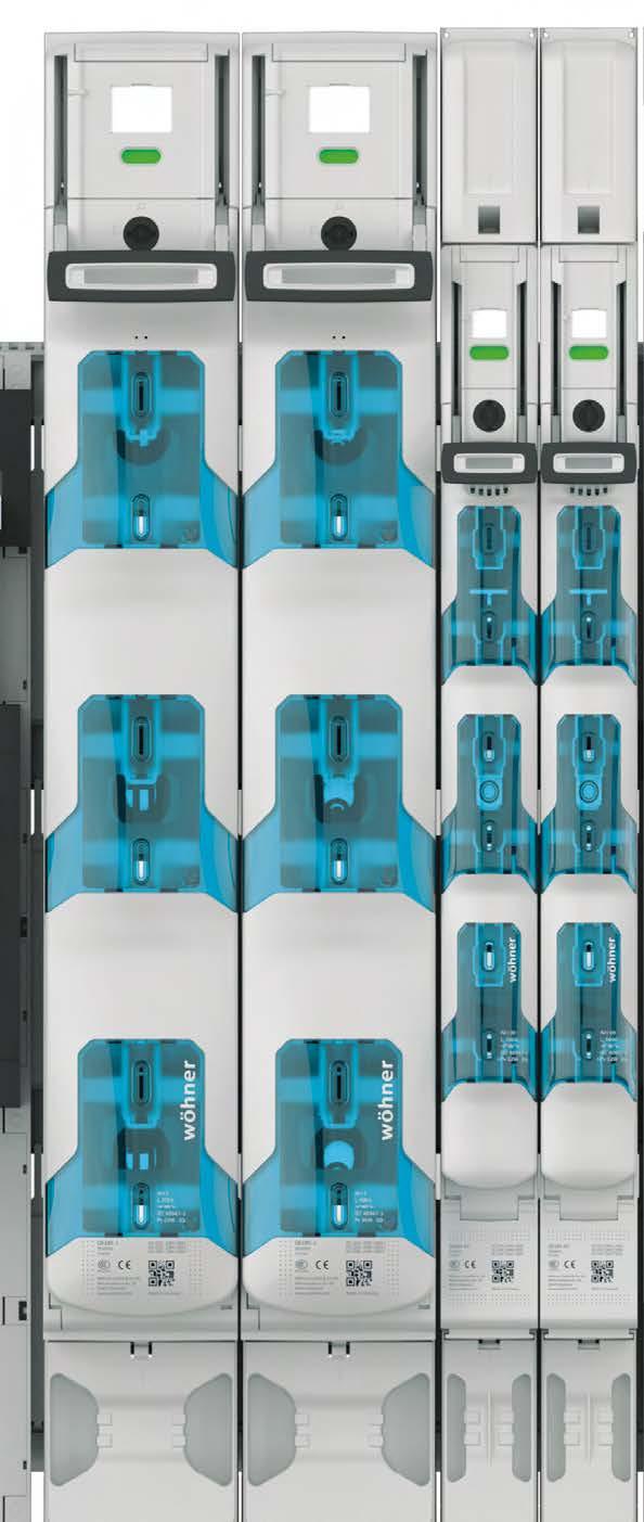
73 185Power 2500 A 4 High-performance system solution with 185 mm busbar spacing The 185Power busbar system by Wöhner is a modular system for low-voltage distribution with 185 mm spacing of the busbars. All the components (i.e. busbar supports, CrossLink covers, NH in-line switch disconnectors, switch-disconnectors fitted with NH fuses, busbar adapters for circuit breakers, connection rails and connection modules) fit together perfectly. The switch disconnector with NH fuses is the special highlight. This version, with the Speed suffix, allows reliable and operator-independent switching. Circuit breakers from 400 A to 1600 A can easily be integrated into the system by means of EQUES adapters. The 185Power allows the user quick and cost-efficient realization of low voltage distribution systems. The modular structure and compatibility of the components among each other contribute to efficient use of space within the cabinet. Systems on the basis of 185Power can easily be expanded or modified.

74 Busbar 185Power 30, 40, 60, 80, 100, mm Tin-plated versions Proven Load current Proven short-circuit capacity UL listed Busbar support Busbar support for easy and safe installation of systems with 185 mm distance between busbar centres Can be aligned with busbars 30, 40, 60, 80, 100, End and centre cover as accessories CRITO 185Power Connection rail The connection rails allow convenient connection of round and flat conductors as well as cable lugs up to 1400 A at just 100 mm wide. Mounting is possible using terminal clamps on the CrossLink touch-safe protection modules, or by using bolts directly on the busbar. QUADRON 185Power Coming in s 00 to 3, the NH in-line switch disconnectors allow quick, easy and safe mounting. Mounting with terminal clamps on CrossLink touch-safe protection modules or direct bolt mounting Integrated current transformer Innovative ventilation duct


75 185Power 2500 A 4 CrossLink 185Power Covering system CRITO 185Power Connection modules In the 185Power system the CrossLink 185Power covering modules, base plate profiles as well as the busbar support cover provide optimum all-around touch-safe protection of the busbar system Versions in 50 and 100 mm width Reliable connection to each other and to the middle and end cover These modules are available in three versions: with a box terminal, for cable lugs, or flat copper to The connection modules can be aligned according to the position of the incoming conductors. The mounting is possible on the CrossLink touch-safe protection modules or directly on the busbar. QUADRON 185Power Speed In-line switch-disconnector with fuses NH in s 00 to 3 allow operator-independent switching Snap-action switch mechanism with double interruption Safer fuse technology Faster and safer mounting with terminal clamp and insulated screw extension Traditional bolt mounting EQUES 185Power Adapter The busbar adapter serves the purpose of quickly and easily mounting any commercially available circuit breaker. The busbar mounting is done via screw type terminal or drill-free terminal clamps on the touch-safe protection system. 400 to 630 A, 150 mm wide 630 to 1600 A, 300 mm wide

76 Power busbar system 3-pole systems Busbar support and busbar support cover Article Type universal busbar support for undrilled flat bars 30, 40, 60, 80, 100, 120 x end cover for busbar support set for one left and one right busbar support centre cover for busbar support when using the busbar support as a centre support Additional busbar supports for drilled busbars and section busbars can be found at Copper Busbar, tin-plated, length 2.40 m Article Crosssection mm² busbar 30 x busbar 40 x busbar 60 x busbar 80 x busbar 100 x busbar 120 x Partial lengths on request CrossLink 185Power, system cover at front Article Type CrossLink touch-safe protection 50 mm wide cover module CrossLink touch-safe protection 100 mm wide cover module front cover IP40 for CrossLink covers completion section 499 mm long completion section 649 mm long The lengths of the completion sections are matched to the lengths of the rear system shrouding; completion section, length 499 mm, suitable for 01420; completion section, length 649 mm, suitable for CrossLink 185Power, system cover at rear system shrouding, rear * set for busbar support distance 550 mm (centre to centre) system shrouding, rear * set for busbar support distance 700 mm (centre to centre) spacer ** set, suitable for * Eight distance pieces are included with the system partitioning ** Set consisting of 4 distance pieces, as an accessory when using a centre bar with system partitioning Busbar connecting terminal, for same- busbar longitudinal busbar connector * 40 mm longitudinal busbar connector * 60 mm touch-safe protection shroud for longitudinal connectors 3-pole, front and rear mounting, cover width 100 mm touch-safe protection shroud for longitudinal connectors 3-pole, front and rear mounting, cover width 150 mm * Two longitudinal Busbar connecting terminal are required for the connection of 80 x 10 mm bars; One longitudinal Busbar connecting terminal and each is required for the connection of 100 x 10 mm bars; Two longitudinal Busbar connecting terminal are required for the connection of 120 x 10 mm bars System mounting instruction: UL certificate
, for 4 cable lugs 240 mm² or flex. copper 80x10 1400 A 100 1 1050.")
77 185Power 2500 A 4 2 CRITO 185Power connection technology 1-pole and 3-pole Connection rail, 3-pole, screw connection for drilled busbars Article Type Rated current Width 3-pole * screw M A pole ** for 3 cable lugs 300mm² (offset arrangement), for 4 cable lugs 240 mm² or flex. copper 80x A Terminal clamps for drill-free mounting with CrossLink touch-safe protection cover, see accessories * Transformer, can be integrated into connection rail, see 4.12 ** Current carrying capacity 1400 A with screw connection, 1200 A with terminal clamp connection, see product description at Accessory for clamp connection, for drill-free mounting on the busbar system Article Type Size terminal clamp for QUADRON 185Power terminal clamp for QUADRON 185Power for busbar systems with CrossLink touch-safe protection for busbar systems without system covers Current transformer module, for connection rails Article Type Size universal current transformer module for mounting in the connection compartment Can only be used with connection rail 01438; for matching transformers see Connection module, 1-pole, clamp connection for drill-free mounting on undrilled busbars connection module for direct cable connection connection module for flex. copper min. 1 / 2x 50 x 10 mm for flex. copper max. 1 / 2x 80 x 10 mm central position connection module for 4 cable lugs M Accessory, cover for Connection module cover cap incl. rear touch protection cover All devices can be mounted directly on busbars 30, 40, 60, 80, 100, 120 x 10 New product Accessories 4.12; 4.16 UL certificate

78 4 3 EQUES 185Power busbar adapter 630 A Universal version Busbar adapter, 630 A, clamp connection for drill-free mounting on the busbar system, with and without CrossLink 185Power touch-safe protection module Type Rated current connection at top, CrossLink clamp connection * connection at bottom, CrossLink clamp connection * * For rated currents see product description at Busbar adapter, 630 A, clamp connection for drill-free mounting on the busbar system, flat installation situation connection at top, flat clamp connection * connection at bottom, flat clamp connection * When installing the adapter incl. circuit breaker, the same installation depth (150 mm supporting edge) is possible as with NH in-line fuse switch disconnector * For rated currents see product description at Busbar adapter, 630 A, screw connection for drilled busbars connection at top / bottom, screw connection * * For rated currents see product description at Accessory, current transformer, accuracy class 1 Article Rated apparent power current transformer 300 A / 5 A 2.50 VA current transformer 400 A / 5 A 2.50 VA current transformer 600 A / 5 A 1.25 VA All devices can be mounted directly on busbars 30, 40, 60, 80, 100, 120 x 10 For further information on current carrying capacity, see product specifications at New product UL certificate

79 185Power 2500 A 4 4 EQUES 185Power busbar adapter 1600 A aligned to switchgear Busbar adapter 1600 A, connection to the system at the top, clamp connection for drill-free mounting on the busbar system, with and without CrossLink 185Power touch-safe protection module ABB Type Rated current for ABB Tmax T7/T6 800 A or T7/T6 630 A 800 A for ABB Tmax T A 1000 A for ABB Tmax T A 1250 A for ABB Tmax T7, Emax A 1320 A For rated currents see product description at Eaton for Eaton NZM A, 800 A, 630 A 1000 A for Eaton NZM A 1250 A for Siemens 3VL A, Eaton NZM A 1440 A For rated currents see product description at Schneider Electric for Schneider Electric NS1000, NS800 or NS630B 1000 A for Schneider Electric NS A for Schneider Electric NS A For rated currents see product description at Siemens for Siemens 3VL5 630 A 630 A for Siemens 3VL6 800 A or 630 A 720 A for Siemens 3VL A 1000 A for Siemens 3VL A 1150 A for Siemens 3VL A, Eaton NZM A 1440 A For rated currents see product description at Socomec for Socomec Sirco 1250 A or 1600 A 1550 A For rated currents see product description at All devices can be mounted directly on busbars 30, 40, 60, 80, 100, 120 x 10 For further information on current carrying capacity, see product specifications at New product Accessories 4.8 UL certificate
80 4 5 EQUES 185Power busbar adapter 1600 A aligned to switchgear Busbar adapter 1600 A, connection to the system at the bottom, clamp connection for drill-free mounting on the busbar system, with and without CrossLink 185Power touch-safe protection module ABB Type Rated current for ABB Tmax T7/T6 800 A or T7/T6 630 A 800 A for ABB Tmax T A 1000 A for ABB Tmax T A 1220 A for ABB Tmax T7, Emax A 1320 A For rated currents see product description at Eaton for Eaton NZM A, 800 A or 630 A 1000 A for Eaton NZM A 1200 A for Siemens 3VL A or Eaton NZM A 1400 A For rated currents see product description at Schneider Electric for Schneider Electric NS1000, NS800 or NS630B 900 A for Schneider Electric NS A for Schneider Electric NS A For rated currents see product description at Siemens for Siemens 3VL5 630A 630 A for Siemens 3VL6 800 A or 630 A 650 A for Siemens 3VL A 1000 A for Siemens 3VL A 1150 A for Siemens 3VL A or Eaton NZM A 1400 A For rated currents see product description at Socomec for Socomec Sirco 1250 A or 1600 A 1500 A For rated currents see product description at All devices can be mounted directly on busbars 30, 40, 60, 80, 100, 120 x 10 For further information on current carrying capacity, see product specifications at New product Accessories 4.8 UL certificate

81 185Power 2500 A 4 6 EQUES 185Power busbar adapter 1600 A aligned to switchgear Busbar adapter 1600 A, connection to the system at the bottom, phase rotation, clamp connection for drill-free mounting on the busbar system, with and without CrossLink 185Power touch-safe protection module ABB Type Rated current for ABB Tmax T A 1220 A for ABB Tmax T7, Emax A 1320 A For rated currents see product description at Eaton for Eaton NZM A 1200 A for Eaton NZM A 1400 A For rated currents see product description at Schneider Electric for Schneider Electric NS A for Schneider Electric NS A For rated currents see product description at Siemens for Siemens 3VL A 1150 A for Siemens 3VL A 1320 A For rated currents see product description at All devices can be mounted directly on busbars 30, 40, 60, 80, 100, 120 x 10 For further information on current carrying capacity, see product specifications at Accessories 4.8 UL certificate

82 4 7 EQUES 185Power busbar adapter 1600 A aligned to switchgear Busbar adapter 1600 A, connection to the system at the top and bottom, screw connection for drilled busbars ABB Type Rated current for ABB Tmax T7/T6 800 A or T7/T6 630 A 800 A for ABB Tmax T A 1000 A for ABB Tmax T A 1220 A for ABB Tmax T7, Emax A 1320 A For rated currents see product description at Eaton for Eaton NZM A, 800 A, 630 A 1000 A for Eaton NZM A 1200 A for Siemens 3VL A, Eaton NZM A 1400 A For rated currents see product description at Legrand for Legrand DPX³ 1600 or GE FK1600 * 1440 A For rated currents see product description at * Only connection to system at the top possible Schneider Electric for Schneider Electric NS1000, NS800 or NS630B 900 A for Schneider Electric NS A for Schneider Electric NS A For rated currents see product description at Siemens for Siemens 3VL5 630 A 630 A for Siemens 3VL6 800 A or 630 A 650 A for Siemens 3VL A 1000 A for Siemens 3VL A 1150 A for Siemens 3VL A, Eaton NZM A 1400 A For rated currents see product description at All devices can be mounted directly on busbars 30, 40, 60, 80, 100, 120 x 10 For further information on current carrying capacity, see product specifications at New product Accessories 4.8 UL certificate

83 185Power 2500 A 4 8 EQUES 185Power busbar adapter 1600 A aligned to switchgear Busbar adapter, 1600 A, connection to the system at bottom, phase rotation, screw connection for drilled busbars ABB Type Rated current for ABB Tmax T A 1220 A for ABB Tmax T7, Emax A 1320 A For rated currents see product description at adapters with phase rotation can also be used with connection to the system at the top Eaton for Eaton NZM A 1200 A for Eaton NZM A 1400 A For rated currents see product description at adapters with phase rotation can also be used with connection to the system at the top Schneider Electric for Schneider Electric NS A for Schneider Electric NS A For rated currents see product description at adapters with phase rotation can also be used with connection to the system at the top Siemens for Siemens 3VL A 1150 A for Siemens 3VL A 1320 A For rated currents see product description at adapters with phase rotation can also be used with connection to the system at the top Accessories, cover IP20 Article Type IP20 Protection cover (front) for adapter, incl. 3 top covers IP20 Protection cover (front) for adapter, incl. 3 top covers touch-safe protection shroud IP20 (rear installation) for ABB Tmax T6/T for Eaton NZM4, Legrand DPX³ 1600, GE FK for Schneider Electric NS1600 NS630B for Siemens 3VL A / 1250 A, 3VL A for Siemens 3VL5 630 A and 3VL6 800 A / 630 A for all adapters Accessory, current transformer, accuracy class 1 Type Rated apparent power current transformer 630 A / 5 A 5.00 VA current transformer 800 A / 5 A 5.00 VA current transformer 1000 A / 5 A 5.00 VA current transformer 1250 A / 5 A 5.00 VA current transformer 1600 A / 5 A 5.00 VA Depending on the adapter type, 1 or 2 current transformers can be used per phase. See adapter product description at All devices can be mounted directly on busbars 30, 40, 60, 80, 100, 120 x 10 For further information on current carrying capacity, see product specifications at New product UL certificate

 NH in-line fuse disconnector, 00,")
84 4 9 QUADRON 185Power NH in-line fuse switch disconnector, 00 3-pole, 1-pole switchable and open version NH in-line fuse disconnector, 00, 3-pole switchable, screw connection for drilled busbars, connection at bottom / top Type Size Rated current screw M8, high version * NH A box terminal 70 mm², high version * NH A screw M8, flat version NH A box terminal 70 mm², flat version NH A Terminal clamps for drill-free mounting with or without CrossLink touch-safe protection cover, see accessories * Current transformer (can be integrated) NH in-line fuse disconnector, 00, 3-pole switchable, screw connection for drilled busbars, connection at bottom / top, with fuse monitoring screw M8, high version * NH A box terminal 70 mm², high version * NH A screw M8, flat version NH A box terminal 70 mm², flat version NH A Terminal clamps for drill-free mounting with or without CrossLink touch-safe protection cover, see accessories * Current transformer (can be integrated) NH in-line fuse disconnector, 00, 1-pole switchable, screw connection for drilled busbars, connection at bottom / top screw M8, high version * NH A box terminal 70 mm², high version * NH A screw M8, flat version NH A box terminal 70 mm², flat version NH A Terminal clamps for drill-free mounting with or without CrossLink touch-safe protection cover, see accessories * Current transformer (can be integrated) NH fuse base, 00, open version, screw connection for drilled busbars, connection at bottom / top screw M8, flat version NH A Terminal clamps for drill-free mounting with or without CrossLink touch-safe protection cover, see accessories Accessory for clamp connection, for drill-free mounting on the busbar system Article Type Size terminal clamp for busbar systems with touch-safe protection terminal clamp IP20 for busbar systems with touch-safe protection terminal clamp for busbar systems without system covers All devices can be mounted directly on busbars 30, 40, 60, 80, 100, 120 x 10 New product Accessories 4.10; 7.5

85 185Power 2500 A 4 10 QUADRON 185Power accessories, 00 3-pole, 1-pole switchable and open version Accessories Article Type Size clamp connector * for Cu mm² wedge clamp terminal * for Cu and Al mm² terminal compartment cover for 33700, 33770, 33720, 33771, 33715, and QUADRON 185Power Speed terminal compartment cover, flat version, connection bottom terminal compartment cover, high version, connection top terminal compartment cover, flat version, connection top for 33704, 33773, 33724, 33774, 33719, 33775, for 33700, 33770, 33720, 33771, 33715, for 33704, 33773, 33724, 33774, 33719, pilot switch changeover 250 V AC/5 A, 30 V DC/4 A lateral bearing strip for front covers lateral cover support for front covers grip lug cover ** for NH base and plug support with mounting rail for CT wiring component support with mount. rails for fuse monitoring and CT wiring When using aluminium conductors, observe the maintenance instructions (see 8.2) * Can only be used for 00, connection screws M8 ** 1 piece required per fuse Current transformer (can be integrated), accuracy class 1 Type Rated apparent power Size current transformer 80 A / 5 A 2.50 VA current transformer 150 A / 5 A 2.50 VA Current transformer (can be integrated), accuracy class 0.5 current transformer 100 A / 5 A 1.50 VA current transformer 150 A / 5 A 2.50 VA Current transformer (can be integrated), accuracy class 0.5; tested in accordance with the conformity procedure current transformer 100 A / 5 A, with declar. of conformity 1.50 VA current transformer 150 A / 5 A, with declar. of conformity 2.50 VA National laws must be observed; in addition to the net price of the transformer, the following cost are charged per transformer for the declaration of conformity, the costs cannot be discounted: Transformers up to 500 A: EUR 37; transformers from 500 A to 1000 A: EUR 54 Double adapter for NH in-line fuse switch disconnectors, 00 for 2 in-lin NH-fuse switch disconnectors Current transformer for double adapter, accuracy class 1 current transformer 150 A / 5 A 1.50 VA Current transformer for double adapter, accuracy class 0.5 current transformer 150 A / 5 A 1.50 VA Current transformer for double adapter, accuracy class 0.5; tested in accordance with the conformity procedure current transformer 150 A / 5 A, with declar. of conformity 1.50 VA National laws must be observed; in addition to the net price of the transformer, the following cost are charged per transformer for the declaration of conformity, the costs cannot be discounted: Transformers up to 500 A: EUR 37; transformers from 500 A to 1000 A: EUR 54 New product

86 4 11 QUADRON 185Power NH in-line fuse switch disconnector, pole, 1-pole switchable and open version NH in-line fuse disconnectors, 1-3, 3-pole switchable, screw connection for drilled busbars, connection at top / bottom Type Size Rated current screw M12 NH A screw M12 NH A screw M12 NH A Terminal clamps for drill-free mounting with or without CrossLink touch-safe protection modules available under accessories NH in-line fuse disconnectors, 1-3, 3-pole switchable, screw connection for drilled busbars, connection at top / bottom, with fuse monitoring screw M12 NH A screw M12 NH A screw M12 NH A Terminal clamps for drill-free mounting with or without CrossLink touch-safe protection modules available under accessories NH in-line fuse disconnectors, 1-3, 1-pole switchable, screw connection for drilled busbars, connection at top / bottom screw M12 NH A screw M12 NH A screw M12 NH A Terminal clamps for drill-free mounting with or without CrossLink touch-safe protection modules available under accessories Double NH in-line fuse disconnectors, 1250 A, 3-pole switchable, screw connection for drilled busbars screw M12, incl. terminal compartment cover NH A Terminal clamps for drill-free mounting with or without CrossLink touch-safe protection modules available under accessories NH in-line fuse base, 1-3, open version, screw connection for drilled busbars, connection at bottom / top screw M12 NH A screw M12 NH A screw M12 NH A Terminal clamps for drill-free mounting with or without CrossLink touch-safe protection modules available under accessories Accessory for clamp connection, for drill-free mounting on the busbar system Article Type Size terminal clamp for QUADRON 185Power terminal clamp for QUADRON 185Power for busbar systems with CrossLink touch-safe protection for busbar systems without system covers All devices can be mounted directly on busbars 30, 40, 60, 80, 100, 120 x 10 Accessories 4.12; 7.6
87 185Power 2500 A 4 12 QUADRON 185Power accessories pole, 1-pole switchable and open version Accessories Article Type Size box terminal * for Cu and Al mm² box terminal * for Cu and Al mm² terminal compartment cover universal for NH-rails 1-3 and connection rail 800 A pilot switch changeover 250 V AC/5 A, 30 V DC/4 A lateral bearing strip for front covers lateral cover support for front covers grip lug cover for 33706, 33707, rear touch-safe protection cover ** rear protection for Phase L plug support with mounting rail for CT wiring component support with mounting rails for fuse monitor and CT wiring * When using aluminium conductors, observe the maintenance instructions (see 8.2) ** To get rear finger safety in combination with CrossLink touch-safe protection modules Current transformer (can be integrated), accuracy class 1 Article Rated apparent power Size current transformer 200 A / 5 A 1.50 VA current transformer 250 A / 5 A 2.50 VA current transformer 400 A / 5 A 2.50 VA current transformer 600 A / 5 A 2.50 VA Can also be used for connection rail Current transformer (can be integrated), accuracy class 0.5 current transformer 200 A / 5 A 1.50 VA current transformer 250 A / 5 A 2.50 VA current transformer 400 A / 5 A 2.50 VA Can also be used for connection rail Current transformer (can be integrated), accuracy class 0.5; tested in accordance with the conformity procedure current transformer 200 A / 5 A, with declaration of 1.50 VA conformity current transformer 250 A / 5 A, with declaration of 2.50 VA conformity current transformer 400 A / 5 A, with declaration of conformity 2.50 VA Can also be used for connection rail National laws must be observed; in addition to the net price of the transformer, the following costs are charged per transformer for the declaration of conformity, the costs cannot be discounted: Transformers up to 500A: EUR 37; transformers from 500A to 1000A: EUR 54 Current transformer module for NH in-line fuse switch disconnectors 1-3 universal current transformer module For matching transformer see page 4.16 for mounting in the connection compartment New product Accessories 4.16

88 4 13 QUADRON 185Power Speed NH fuse-switch disconnector, 00 with snap-action switch mechanism In-line switch-disconnector with fuses NH, 00, 3-pole switchable, clamp connection for drill-free mounting with and without CrossLink touch-safe protection modules, connection screw M8 Type Size Rated current high version, outgoing terminals at the bottom * NH A high version, outgoing terminals at the top * NH A flat version, outgoing terminals at the bottom NH A flat version, outgoing terminals at the top NH A With three terminal clamps with insulated screw extension for mounting on the busbar system * Current transformer, can be integrated; combinable with s 1 3 In-line switch-disconnector with fuses NH, 00, 3-pole switchable clamp connection for drill-free mounting with and without CrossLink touch-safe, with fuse monitoring, protection modules, connection screw M8 high version, outgoing terminals at the bottom * NH A high version, outgoing terminals at the top * NH A flat version, outgoing terminals at the bottom NH A flat version, outgoing terminals at the top NH A With three terminal clamps with insulated screw extension for mounting on the busbar system * Current transformer, can be integrated; combinable with s 1 3 In-line switch-disconnector with fuses NH, 00, 3-pole switchable screw connection for drilled busbars, connection screw M8 high version, outgoing terminals at the bottom * NH A high version, outgoing terminals at the top * NH A flat version, outgoing terminals at the bottom NH A flat version, outgoing terminals at the top NH A With three screws for mounting on the busbar system * Current transformer, can be integrated; combinable with s 1 3 In-line switch-disconnector with fuses NH, 00, 3-pole switchable screw connection for drilled busbars, connection screw M8, with fuse monitoring, high version, outgoing terminals at the bottom * NH A high version, outgoing terminals at the top * NH A flat version, outgoing terminals at the bottom NH A flat version, outgoing terminals at the top NH A With three screws for mounting on the busbar system * Current transformer, can be integrated; combinable with s 1 3 All devices can be mounted directly on busbars 30, 40, 60, 80, 100, 120 x 10; Fuse links are not included in the scope of delivery New product Accessories 4.14; 7.5

89 185Power 2500 A 4 14 QUADRON 185Power Speed accessories, 00 Accessories Article Type Size terminal compartment cover for 33700, 33770, 33720, 33771, 33715, and QUADRON 185Power Speed 00 rear touch-safe protection * for terminal compartment clamp connector * for Cu mm² wedge clamp terminal * for Cu and Al mm² bearing area extension, top for front covers lateral bearing strip for front covers lateral cover support for front covers pilot switch changeover 250 V AC / 5 A, 30 V DC / 4 A When using aluminium conductors, observe the maintenance instructions (see 8.2) * Can only be used for 00, connection screws M8 Current transformer (can be integrated), precision class 1 Article Rated apparent power Size current transformer 80 A / 5 A 2.50 VA current transformer 150 A / 5 A 2.50 VA Current transformer (can be integrated), accuracy class 0.5 current transformer 150 A / 5 A 2.50 VA current transformer 150 A / 5 A 2.50 VA Current transformer (can be integrated), accuracy class 0.5; tested in accordance with the conformity procedure current transformer 100 A / 5 A, with declar. of conformity 1.50 VA current transformer 150 A / 5 A, with declar. of conformity 2.50 VA National laws must be observed; in addition to the net price of the transformer, the following cost are charged per transformer for the declaration of conformity, the costs cannot be discounted: Transformers up to 500 A: EUR 37; transformers from 500 A to 1000 A: EUR 54 Double adapter for QUADRON 185Power Speed NH fuse-switch disconnector, 00 for 2 in-lin NH-fuse switch disconnectors Current transformer for double adapter, accuracy class 1 current transformer 150 A / 5 A 1.50 VA Current transformer for double adapter, accuracy class 0.5 current transformer 150 A / 5 A 1.50 VA Current transformer for double adapter, accuracy class 0.5; tested in accordance with the conformity procedure current transformer 150 A / 5 A, with declar. of conformity 1.50 VA National laws must be observed; in addition to the net price of the transformer, the following cost are charged per transformer for the declaration of conformity, the costs cannot be discounted: Transformers up to 500 A: EUR 37; transformers from 500 A to 1000 A: EUR 54 New product

90 4 15 QUADRON 185Power Speed NH fuse-switch disconnector, 1-3 with snap-action switch mechanism In-line switch-disconnector with fuses NH, 1-3, 3-pole switchable screw connection for drilled busbars, connection screw M12 Type Size Rated current outgoing terminals at the bottom NH A outgoing terminals at the top NH A outgoing terminals at the bottom NH A outgoing terminals at the top NH A outgoing terminals at the bottom NH A outgoing terminals at the top NH A Terminal clamps for mounting on CrossLink touch-safe protection modules or screws for mounting on the busbar system are required available under accessories In-line switch-disconnector with fuses NH, 1-3, 3-pole switchable screw connection for drilled busbars with fuse monitoring, connection screw M12 outgoing terminals at the bottom NH A outgoing terminals at the top NH A outgoing terminals at the bottom NH A outgoing terminals at the top NH A outgoing terminals at the bottom NH A outgoing terminals at the top NH A Terminal clamps for mounting on CrossLink touch-safe protection modules or screws for mounting on the busbar system are required available under accessories Accessories for mounting on the busbar system Article Type Size mounting set with 3 terminal clamps mounting set with 3 bolts insulated screw extension for terminal clamp Accessories terminal compartment cover for drill-less mounting on the busbar system, with and without CrossLink touch-safe protection covers for busbar connection on drilled busbars, including positioner for safe live working with standard tools universal for NH-rails 1-3 and connection rail 800 A rear cover for terminal compartment cover connection set box terminal 70 mm² 240 including rear cover mm² connection set box terminal 120 mm² including rear cover mm² bearing area extension, top lateral bearing strip for front covers lateral cover support for front covers pilot switch changeover 250 V AC / 5 A, 30 V DC / 4 A All devices can be mounted directly on busbars 30, 40, 60, 80, 100, 120 x 10; Fuse links are not included in the scope of delivery New product Accessories 4.15; 7.6
91 185Power 2500 A 4 16 QUADRON 185Power Speed accessories, 1-3 Current transformer module, for QUADRON 185Power Speed NH fuse-switch disconnector, 1-3 Article Type Size universal current transformer module including front and rear cover for mounting in the connection compartment Current transformer (can be integrated into transformer module), accuracy class 1 Type Rated apparent power current transformer 250 A / 5 A 5.00 VA current transformer 400 A / 5 A 5.00 VA current transformer 600 A / 5 A 5.00 VA current transformer 750 A / 5 A 5.00 VA Current transformer (can be integrated into transformer module), accuracy class 0.5 current transformer 250 A / 5 A 5.00 VA current transformer 400 A / 5 A 5.00 VA current transformer 600 A / 5 A 5.00 VA current transformer 750 A / 5 A 5.00 VA Current transformer (can be integrated into transformer module), accuracy class 0.5; tested in accordance with the conformity procedure current transformer 250 A / 5 A, with declaration of conformity 5.00 VA current transformer 400 A / 5 A, with declaration of conformity 5.00 VA current transformer 600 A / 5 A, with declaration of conformity 5.00 VA current transformer 750 A / 5 A, with declaration of conformity 5.00 VA National laws must be observed; in addition to the net price of the transformer, the following cost are charged per transformer for the declaration of conformity, the costs cannot be discounted: Transformers up to 500 A: EUR 37; transformers from 500 A to 1000 A: EUR 54 New product

92 Centre feed unit

93 5

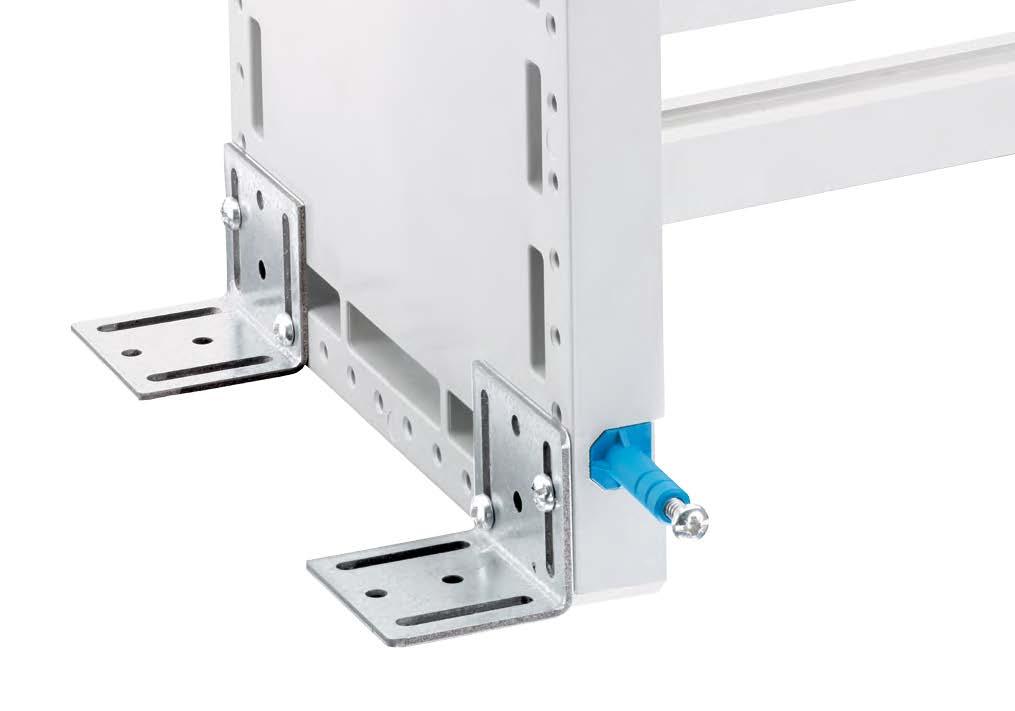
94 Centre feed unit


95 Centre feed unit 5 Centre feed unit up to 4000 A combines the advantages of high short-circuit capacity, drill-free mounting, brace terminal technology and clearly structured design. The fuseless equipment practice of this system puts high requirements on the short circuit capacity. The busbar supports and centre feed units have been designed specifically for this purpose. This also concerns the large number of different connection options for copper and aluminium conductors, no matter if they are round conductors or laminated or large flat conductor connections. Industrial production and type tests ensure compliance with the required safety standards. The current rating and short-circuit capacity up to 120 ka determined by means of the type test meet the high requirements put on this system.
96 Double and triple T and TCC section busbars CRITO Connection technology The profiled section busbars offer safe distribution of currents up to 4000 A, double T and triple T section busbars can be connected on both sides. Versions: Double T section busbars Triple T section busbars TCC section busbars These solutions provide for convenient connection of round conductors, flat conductors and cable lugs. Currents up to 3200 A can be brought to the busbar by the individual components. Brace terminal technology Round, sectored and flat conductors UL listed
97 Centre feed unit 5 Busbar support multi-pole The busbar supports are suitable for 3 or 4 pole installations. Busbars from 300 to 1140 mm² can be used. Variable build up Double T and triple T sections busbars can be used Busbar support 1 pole The 1 pole lateral busbar support can also accommodate the TCC section busbars. Busbars from 500 to 1600 mm² can be used Variable build up Double-T, Triple-T, and TCC section busbars can be used
98 5 1 Centre feed unit TT and TTT section busbars Centre feed unit Cabinet width Mounting dimensions Busbar length Crosssection mm² for cabinet width 600 mm for cabinet width 800 mm for cabinet width 600 mm for cabinet width 800 mm for cabinet width 600 mm for cabinet width 800 mm Universal conductor connection terminal 16 mm² to 300 mm² For busbar Connection min. max. Terminal space W x H For use up to max. flat busbars 10 mm and section busbars mm², AWG 4 17 x A MCM x 10 and section busbars mm² 41 x A Brace terminals for round conductors up to 300 mm² For busbar Connection min. - max. For use up to max. 20, 25, 30 x 5, 10 and section busbars * Cu / Al mm² 500 A , 25, 30 x 5, 10 and section busbars * Cu / Al mm² 600 A * When using aluminium conductors, observe the maintenance instructions (see 8.2) Profile terminal, for double-t section busbars, at front and back of busbar section Connection cross-section End feed Centre feed Terminal space W x H mm² 1600 A 1600 A 41 x mm² 51 x mm² 64 x mm² 2000 A 51 x mm² 64 x mm² 2500 A 81 x mm² 2800 A 101 x mm² 1600 A 41 x mm² 2000 A 2500 A 64 x mm² 2500 A 3200 A 101 x For the connection of flat busbars and laminated copper busbars Accessories 7.12; 7.13 UL certificate

99 Centre feed unit 5 2 Centre feed unit TT and TTT section busbars Brace terminals, 55 to 105 mm wide, for flat conductors For busbar Terminal space W x H End feed Centre feed 30 x 10 and section busbars 55 x A 2000 A x 10 and section busbars 68 x x 10 and section busbars 105 x A For the connection of flat busbars and laminated copper busbars Clip-on screw connection, attachable, for DIN cable lugs For busbar Terminal space W x H For use up to max. 12, 15, 20, 25, 30 x 10 and section busbars M8 x A , 15, 20, 25, 30 x 10 and section busbars M10 x A Laminated copper busbars, insulated, length 2 m Dimensions (Number of laminates x width x thickness) Rated current at 30 K Rated current at 50 K Crosssection mm² 10 x 40 x A 1053 A x 50 x A 1244 A x 63 x A 1481 A x 80 x A 1777 A x 100 x A 2110 A You will find more laminated copper bars in the "accessories" chapter Components, for individual mounting Article Type busbar support, lateral for centre feed unit with double T and triple T busbars busbar support, 4-pole, centre for centre feed unit with double T busbars busbar support, 3-pole, centre for centre feed unit with triple T busbars additional cover holder for centre feed unit Section busbars, copper Article Type Busbar length double-t section busbar 500 mm² length 453 mm, tinned double-t section busbar 500 mm² length 650 mm, tinned double-t section busbar 720 mm² length 453 mm, tinned double-t section busbar 720 mm² length 653 mm, tinned triple-t section busbar 1140 mm² length 453 mm, tinned triple-t section busbar 1140 mm² length 653 mm, tinned For current carrying capacity of the busbars visit Accessories 7.12; 7.13 UL certificate

100 5 3 Centre feed unit TT, TTT and TCC section busbars Busbar holder, 1-pole, lateral Type for section busbar TT, TTT and TCC Section busbar, copper, tin-plated Type Length TCC section busbar 1600 mm² For current carrying capacity of the busbars visit Connection screw, with nut and spring washer for TCC section busbars Type Connection hammer-head screw for TCC-profile, with nut and spring washer M 10 x bolt for TCC-profile, with nut and spring washer M 12 x For current carrying capacity of the busbars visit Brace terminal, 95 to 300 mm 2, for round conductors For busbar Connection mm² For use up to max. 20, 25, 30 x 5, 10 and section busbars * A , 25, 30 x 5, 10 and section busbars * A * When using aluminium conductors, observe the maintenance instructions (see 8.2) Brace terminal, 30 to 105 mm wide, for flat conductors For busbar Terminal space W x H End feed Centre feed 20, 25, 30 x 5, 10 and section busbars 30 x A 750 A x A x 10 and section busbars 55 x A 2000 A x x A Accessories 7.12; 7.13 UL certificate
101 Centre feed unit 5 4

102 Panel Panel mounted components and switching devices
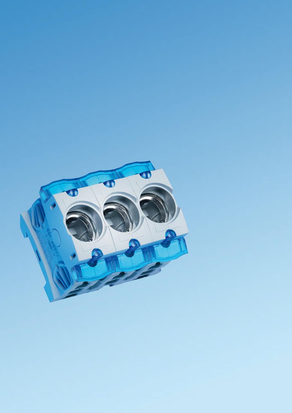
103 6


104 MOUNTING PLATE OR MOUNTING RAIL COMPONENTS Panel


105 Panel Panel mounted components and switching devices 6 Components for conventional mounting For conventional wiring, Wöhner offers a comprehensive range of components for mounting rail or mounting plate assembly. The fuse technology and associated connection technology meet the high safety and quality requirements set by international standards. Thanks to their snap-action switch mechanisms the switching devices offer high switching capacity and special protection through operator-independent switching. Selected products are ideal for special applications in the field of photovoltaics.


 85 fuses to 1500 V DC Equipment width: 22.5 mm UL approved SECUR Panel The D0 fuse-switch disconnector offers a high degree of safety and comfort for the operator.")

106 CUSTO Panel The CUSTO fuse base D01 and D02 for installation in the 45 mm standard field section offers a high level of safety and favourable connection conditions. Wide terminal range up to 35 mm² Dual function terminal for 2 conductors, 35 mm² + 16 mm² Connection of different conductors Integrated cover and comprehensive touch-safe protection TRITON Panel The TRITON fuse bases D01, D02, DII and DIII in especially robust design with touch-safe protection according to DGUV V3 for industrial applications Wide terminal range up to 35 mm² Dual-function terminal incoming side Connection of different conductors Spring loaded contact Versions in DII and DIII Versions with screw mounting SECUR Panel The SECUR fuse holder especially for photovoltaic applications allows for a comfortable fuse change by means of a removable fuse carrier. The contacts in the carrier remain protected against touch. For 10 (14) 85 fuses to 1500 V DC Equipment width: 22.5 mm UL approved SECUR Panel The D0 fuse-switch disconnector offers a high degree of safety and comfort for the operator. The fuse replacement is only possible when switched off. Dual-function terminal to 35 mm² Captive fuse carrier with commercial gauge ring Optional auxiliary switch CAPUS Panel This product series includes three families. Switch disconnections with NH fuses from 160 A to 630 A Switch disconnectors from 125 A to 3150 A Changeover switch from 125 A to 1000 A. 3 pole + N versions available MOTUS Panel With the MOTUS hybrid motor starter Drives up to 4 kw can be operated. By means of the integrated functions direct and reversing starter, over load protection and emergency stop significantly reduces the space requirement and wiring cost. 3 design versions: up to 0.6 A, up to 2.4 A and up to 9 A Equipment width: 22.5 mm Up to 30 mil. switching cycles UL listed
107 Panel Panel mounted components and switching devices 6 AMBUS Panel The carrier for the cylindrical fuses is available in 1, 2 and 3 pole as well as in versions with neutral conductor, with LED, with auxiliary switch as well as for semiconductor protection. 32 A (10 38), 50 A (14 51), 100 A (22 58) Rated voltage to 690 V Touch-safe protection after VDE 0106 Photovoltaic variants to 1000 V DC are also UL approved AMBUS Panel UL Version Versions for class CC to 30 A and class J to 60 A fuses according to UL All products are touch-safe protected and have convenient connection technology. Short-circuit capacity up to 200 ka Rated voltage to 600 V Versions available with LED as fuse indicator QUADRON Panel The NH fuse-switch disconnector for Sizes 000 to 4a protect and disconnect currents up to 1600 A. NH 000 to 2 can also be mounted on mounting rail NH 00 to 3 - versions with fuse monitoring Various accessories for connection and shrouding QUADRON Panel Speed One highlight is the QUADRON Panel switch disconnector with NH fuses. Its snap-action switch mechanism allows safe, operator-independent switching. Double interruption Lockable in off-position FLAG indicator for switch position indicator Versions with rotary drive or fuse monitoring
108 6 1 MOTUS Panel - Hybrid-Motor starter for switching of inductive loads Hybrid motor starter, with reversing function and CrossLink Technology, 22.5 mm wide for mounting on mounting rails TH35 acc. to EN Type Width Height Depth A direct and reversing starter A direct and reversing starter A direct and reversing starter MOTUS accessories connecting plug with cable connection, 2 units connecting plug with cable connection, 3 units connecting plug with cable connection, 4 units MOTUS replacement components electronic unit A direct and reversing starter electronic unit A direct and reversing starter electronic unit A direct and reversing starter adapter for MOTUS Panel fuse 16 A for version 0.6 A and 2.4 A fuse 20 A for version 9 A fuse 30 A for version 9 A for motors with heavy-duty starting New product UL certificate
109 CUSTO Panel - D0 integrated fuse base version with touch-safe protection, dual-function terminal on both sides Panel-mounted components and switching devices 6 2 D0 fuse base, version for distribution boards Type Rated voltage Poles Connection mm² E 14 / 16 A / 1P 400 V 1-pole E 14 / 16 A / 3P 3-pole E 18 / 63 A / 1P 1-pole E 18 / 63 A / 3P 3-pole Comb-type busbar, pitch 27 mm, length 1 m Type Centre feed End feed Crosssection mm² comb-type busbar, 1-pole, bridge type, pitch 27 mm 130 A 80 A A 130 A comb-type busbar, 3-pole, bridge type, pitch 27 mm 130 A 80 A A 130 A Connection terminal, for comb-type busbars, bridge version Article Connection min. max. Type connection terminal, side connection 6-50 mm² for 31014, 31024, 31309, Rated current 125 A connection terminal, side connection for connection terminal, front connection connection terminal, front connection for A connection terminal, front connection mm² for A connection terminal is required for each phase End cover Type for 2-pole and 3-pole comb-type busbars 16 mm² for 3-pole comb-type busbars 35 mm² Accessories 7.1; 7.2
110 6 3 TRITON Panel - D0 panel-mounting fuse base Touch-safe protection in accordance with EN / DGUV V3 for industrial applications with dual-function terminal on incoming connection, box terminal on outgoing terminal D0 fuse base, industrial version, pitch 27 mm Type Rated voltage Poles Connection mm² E 14 / 16 A / 1P 400 V 1-pole E 14 / 16 A / 3P 400 V 3-pole E 18 / 63 A / 1P 400 V 1-pole E 18 / 63 A / 3P 400 V 3-pole Comb-type busbar, pitch 27 mm, length 1 m Type Crosssection mm² Centre feed End feed comb type busbar, 1-pole, fork type, pitch 27 mm A 80 A comb type busbar, 3-pole, fork type, pitch 27 mm comb-type busbar, 1-pole, bridge type, pitch 27 mm comb-type busbar, 3-pole, bridge type, pitch 27 mm A 130 A End cover, for insulated comb-type busbars for 2-pole and 3-pole comb-type busbars 16 mm² for 3-pole comb-type busbars 35 mm² Connection terminal, for insulated comb-type busbars, bridge version Article Type Connection Rated mm² current connection terminal, side connection for 31014, A , 31309, connection terminal, side connection for A connection terminal, front connection for A connection terminal, front connection for A A connection terminal is required for each phase Label holder Type for Triton, snap-on Label, for label holder Clip 20 x Accessories 7.1; 7.2
111 Panel-mounted components and switching devices 6 4 SECUR Panel - Switch disconnector with D0 fuse 63 A Touch-safe protection in accordance with DIN EN 50274/DGUV V5, dual-function terminal on both sides D0 switch disconnector with fuses Type Rated current Connection mm² 1-pole 63 A pole+N pole pole pole+N V AC / 130 V DC for 2-pole version D0 switch disconnector with fuses, with LED 1-pole 63 A pole V AC / 130 V DC for 2-pole version LED signals tripped fuse Reducer Type reducer D02 for D01 fuses 2-16 A Pilot switch, for monitoring the switch position, 9 mm wide changeover 400 V AC / 2 A, 24 V DC / 6 A Comb-type busbar, length 1 m Type Crosssection mm² Centre feed End feed comb-type busbar, 1-pole, bridge type, pitch 27 mm A 80 A A 130 A comb-type busbar, 3-pole, bridge type, pitch 27 mm A 80 A A 130 A End cover, for insulated comb-type busbars Type for 2-pole and 3-pole comb-type busbars 16 mm² for 3-pole comb-type busbars 35 mm² Connection terminal, for comb-type busbars, bridge version Article Type Connection Part No. mm² connection terminal, side connection for 31014, 31024, , for connection terminal, front connection for for for A connection terminal is required for each phase Fuse links not included Accessories 7.1
112 6 5 TRITON Panel D fuse base Touch-safe protection in accordance with EN / DGUV V3 for industrial applications D fuse base, industrial version, for screw-in gauge rings Type Rated voltage Poles Connection mm² E 27 / 25 A / 1P, for screw-in gauge rings 500 V E 27 / 25 A / 3P, for screw-in gauge rings 500 V E 33 / 63 A / 1P, for screw-in gauge rings * 500 V E 33 / 63 A / 3P, for screw-in gauge rings * 500 V * Conforms to VDE , also 690 V AC / 600 V DC Comb-type busbar, length 1 m Type Crosssection mm² Centre feed End feed 1-pole comb-type busbar, insulated, for E A 80 A pole comb-type busbar, insulated, for E pole comb type busbar, insulated, for E pole comb-type busbar, insulated, for E End cover, for insulated comb-type busbars Type for 2-pole and 3-pole comb-type busbars 16 mm² Connection terminal, for insulated comb-type busbars Article Type Connection Rated mm² current connection terminal, side connection for 31014, A , 31309, connection terminal, side connection for connection terminal, front connection A connection terminal is required for each phase Label holder Type for Triton, snap-on Label, for label holder Clip 20 x Accessories 7.1
113 Panel-mounted components and switching devices 6 6 AMBUS Panel - Fuse holder for IEC cylindrical fuses Type AES with box terminals, with touch-safe protection in accordance with EN Fuse holder for cylindrical fuses, standard version Type Rated current Poles Connection Width 10x38 32 A 1-pole 0,75-25 mm² / AWG pole pole x51 50 A 1-pole mm² / AWG pole pole x A 1-pole 4-50 mm² / AWG 10-1/ pole pole Fuse holder for cylindrical fuses, standard version with LED V AC/DC 10x38 32 A 1-pole 0,75-25 mm² / AWG x38 2-pole x38 3-pole x51 50 A 1-pole 1,5-35 mm² / AWG x51 3-pole x A 1-pole 4-50 mm² / AWG 10-1/ x58 3-pole LED signals tripped fuse Fuse holder for cylindrical fuses, standard version with LED V AC/DC 10x38 32 A 1-pole 0,75-25 mm² / AWG LED signals tripped fuse Fuse holder for cylindrical fuses, standard version, neutral conductor on right 10x38 32 A 1-pole+N 0,75-25 mm² / AWG x38 3-pole+N x51 50 A 1-pole+N 1,5-35 mm² / AWG x51 3-pole+N x A 1-pole+N 4-50 mm² / AWG 10-1/ x58 3-pole+N Fuse holder for cylindrical fuses, standard version, neutral conductor on left 14x51 50 A 3-pole+N 1,5-35 mm² / AWG x A 3-pole+N 4-50 mm² / AWG 10-1/ Fuse holder for cylindrical fuses, standard design, integrated neutral conductor (left) 10x38 32 A 1-pole+N 1,5-35 / AWG x38 3-pole+N N-module 10x38 32 A N 0,75-25 mm² / AWG Accessories 7.7; 7.8 UL certificate
114 6 7 AMBUS Panel - Fuse holder for IEC cylindrical fuses Type AES with box terminals, with touch-safe protection in accordance with EN Fuse holder for cylindrical fuses, version for semiconductor protection fuses Type Rated current Poles Connection Width 10x38 32 A 1-pole 0,75-25 mm² / AWG pole pole x51 50 A 1-pole 1,5-35 mm² / AWG pole pole x A 1-pole 4-50 mm² / AWG 10-1/ pole pole Fuse holder for cylindrical fuses, version for semiconductor protection fuses, with pilot switch 14x51 50 A 1-pole 1,5-35 mm² / AWG x51 2-pole x51 3-pole x A 1-pole 4-50 mm² / AWG 10-1/ x58 2-pole x58 3-pole Pilot switch indicates when no fuse is inserted, holder is open, or fuse (with striker) is tripped Fuse holder for cylindrical fuses, photovoltaic version 10x38 / 1P 30 A 1-pole 0,75-25 mm² / AWG x38 / 1P / LED * 1-pole x38 / 2P 2-pole * LED indicates blown fuse, operating range V Fuse holder for cylindrical fuses, photovoltaic version 10x85 * 32 A 1-pole 0,75-25 mm² / AWG * Also suitable for 14 x 85 fuses Accessories 7.7; 7.8 UL certificate
115 Panel-mounted components and switching devices 6 8 AMBUS Panel accessories for AES holder for cylindrical fuses Connection sets, for custom combinations of multipole units Type connection kit 10x38, 2-pole connection kit 10x38, 3-pole connection kit 14x51, 2-pole multipole devices can be produced with each set, depending on the version (2 or 3-pole) Spacer 4.5 mm, set for 50 fuse holders set for 50 fuse holders and Comb-type busbar, length 1m Type Crosssection mm² Centre feed End feed comb-type busbar, 1-pole, bridge type, pitch 18 mm A 80 A comb-type busbar, 3-pole, bridge type, pitch 18 mm comb-type busbar, 1-pole, bridge type, pitch 27 mm comb-type busbar, 3-pole, bridge type, pitch 27 mm comb-type busbar, 1-pole, bridge type, pitch 18 mm A 100 A comb-type busbar, 2-pole, bridge type, pitch 18 mm comb-type busbar, 3-pole, bridge type, pitch 18 mm comb-type busbar, 1-pole, bridge type, pitch 27 mm A 130 A comb-type busbar, 3-pole, bridge type, pitch 27 mm End cover, for comb-type busbars Type PG Part No. for 2-pole and 3-pole comb-type busbars 16 mm² for 1-pole comb-type busbars 25 mm² for 2-pole and 3-pole comb-type busbars 25 mm² for 3-pole comb-type busbars 35 mm² Connection terminal, for comb-type busbars Article Type Connection Rated mm² current connection terminal, side connection for A and connection terminal, front connection for and for A for 31549, connection terminal, side connection for 31014, A , 31309, for connection terminal, front connection for for A for A connection terminal is required for each phase UL certificate
116 AMBUS Panel, fuse holder for Class CC fuses Type AES with box terminals, with touch-safe protection in accordance with EN 50274, for fuses that conform to UL Class CC fuse holder for cylindrical fuses, Class CC, standard version Type Poles Connection Width 30 A / 600 V 1-pole 0,75-25 mm² / AWG A / 600 V 2-pole A / 600 V 3-pole Class CC fuse holder for cylindrical fuses, Class CC, standard version with LED V AC/DC 30 A / 600 V 1-pole 0,75-25 mm² / AWG A / 600 V 2-pole A / 600 V 3-pole LED signals tripped fuse Class CC fuse holder for cylindrical fuses, Class CC, standard version with LED V AC/DC 30 A / V 1-pole 0,75-25 mm² / AWG LED signals tripped fuse Comb-type busbar, length 1 m, pitch 18 mm Type Crosssection mm² Centre feed End feed comb-type busbar, 1-pole, bridge type, pitch 18 mm A 100 A comb-type busbar, 2-pole, bridge type, pitch 18 mm comb-type busbar, 3-pole, bridge type, pitch 18 mm Connection terminal, for comb-type busbar Type Connection mm² for for 31549, A connection terminal is required for each phase End cover, for comb-type busbar Type for 1-pole comb-type busbars 25 mm² for 2-pole and 3-pole comb-type busbars 25 mm² Accessories 7.9 UL certificate
117 Panel-mounted components and switching devices 6 10 AMBUS Panel - QUADRON Panel - Fuse holder for Class J with touch-safe protection, for fuses that comply with UL Class J fuse holder, AMBUS Panel, clip-on mounting, standard version Type Poles Connection Width 30 A / 600 V (21 x 57) 1-pole 0,75-50 mm² / AWG pole pole A / 600 V (27 x 60) 1-pole 2,5-50 mm² / AWG pole pole Class J fuse holder, AMBUS Panel, clip-on mounting, standard version with LED V AC/DC 30 A / 600 V (21 x 57) 1-pole 0,75-50 mm² / AWG A / 600 V (21 x 57) 2-pole A / 600 V (21 x 57) 3-pole A / 600 V (27 x 60) 1-pole 2,5-50 mm² / AWG A / 600 V (27 x 60) 2-pole A / 600 V (27 x 60) 3-pole LED signals tripped fuse Class J fuse holder, QUADRON Panel, for screwing onto mounting plate 100 A / 600 V (29 x 117) * 3-pole 4-50 mm² / AWG 14-2/ A / 600 V (41 x 146) * mm² / AWG MCM A / 600 V (54 x 181) mm² / AWG 4 - MCM * Do not use fuse links with sharp-edged blades Accessories 7.10; 7.11 UL certificate

118 6 11 QUADRON Panel, NH fuse bases Fuse holder for NH fuses and NH-PV fuses NH fuse base for photovoltaic, 1-pole, with touch-safe protection, screw on both sides, 1000 V AC / 1500 V DC Type Rated Rated Size current voltage both sides screw M A 1500 V NH 1XL both sides screw M12 * 600 A 1500 V NH 2XL / 3L * For fuse link NH 2XL or NH 3L in accordance with IEC with max. 100 W power dissipation NH fuse base for photovoltaic, 1-pole, with touch-safe protection, 1000 V AC / 1500 V DC incoming connection screw M10, outgoing connection 250 A 1500 V NH 1XL to busbar 2x30x10 incoming connection screw M10, outgoing connection 250 A 1500 V NH 1XL to busbar 2x30x10, for integrated mounting of CTs type LEM HTA incoming connection screw M10, outgoing connection to busbar 2x40x10 * 600 A 1500 V NH 2XL / 3L * For fuse link NH 2XL or NH 3L in accordance with IEC with max. 100W power dissipation Information on rated load factors with regard to current carrying capacity is available on request or at Accessories Type grip lug cover * * 2 pieces required per fuse NH fuse base, 00, barrier version Type Rated current Size Number of poles Connection mm² both sides screw M8, without barrier 160 A NH both sides screw, with 2 barriers both sides terminal, without barrier both sides clamp, with 2 barriers NH fuse base, , version with touch-safe protection both sides screw M8 160 A NH both sides clamp both sides screw M A NH both sides clamp both sides screw M A NH both sides screw M A NH Accessories 7.5; 7.6 UL certificate

119 Panel-mounted components and switching devices 6 12 QUADRON Panel accessories for NH fuse holders Grip lug cover, fits NH bases with touch-safe protection Type Size for NH base and * XX,YY for NH fuse base ** XX,YY * 1 piece required per fuse ** 2 pieces required per fuse Barrier and barrier support Article Type barrier for fuse base NH 00 for 03350, 03351, 03354, XX,YY barrier support, for lateral barrier for 03350, 03351, 03354, XX,YY Neutral conductor, screw-on mounting Rated current Type Connection mm² 160 A clamp, both sides XX,YY A screw M8 at both sides XX,YY Neutral conductor, disconnectable, screws-on or clip-on onto mounting rail TH 35 (EN 60715) 63 A XX,YY Neutral conductor, disconnectable, screw-on mounting Rated current Type Length Connection mm² 160 A clamp on both sides XX,YY A screw M8 at both sides XX,YY A screw M10 at both sides XX,YY A screw M12 at both sides XX,YY Connecting terminal 160 A both sides clamp XX,YY A both sides clamp XX,YY A both sides screw M XX,YY A both sides screw M XX,YY A both sides screw M XX,YY A both sides screw M XX,YY Possible combinations: 3-pole NH bases with neutral conductor (neutral conductor attachable to NH base) (clamp on both sides) (M8 screw on both sides) Other combinations possible if the neutral conductors are fitted separately

120 6 13 QUADRON Panel - NH fuse-switch disconnector 000 to 3 Type LTS and QCB for panel mounting NH fuse-switch disconnector, 000 to 3, 3-pole Type Rated current Size box terminal 125 A NH clamp 70 mm² 160 A NH screw M box terminal 250 A NH screw M screw M A NH screw M A NH NH fuse-switch disconnector, 4a, 3-pole 2x screw M A NH 4a NH fuse-switch disconnector, 00, 3-pole, switchable, with short touch-safe protection clamp 70 mm², with short protection cover 160 A NH screw M8, with short protection cover NS fuse-switch disconnector, 00 to 3, 3-pole, with electronic fuse monitoring clamp 70 mm² 160 A NH screw M screw M A NH screw M A NH screw M A NH Circuit diagram for fuse monitoring is available at NH fuse-switch disconnector, 00 to 3, 3-pole, with electromechanical fuse monitoring clamp 70 mm² 160 A NH screw M screw M A NH screw M A NH screw M A NH Circuit diagram for fuse monitoring is available at Accessories ; UL certificate

121 Panel-mounted components and switching devices 6 14 QUADRON Panel accessories NH fuse-switch disconnector, 000 to 3 Comb-type busbars, closed version with end covers Type Crosssection mm² Usable with comb-type busbar, 3-pole, for 2 NH fuse switch disconnectors comb-type busbar, 3-pole, for 2 NH fuse switch disconnectors comb-type busbar, 3-pole, for 3 NH fuse switch disconnectors comb-type busbar, 3-pole, for 4 NH fuse switch disconnectors Connection terminal, for comb-type busbar Type for 3-pole comb-type busbar 35 mm², suitable for NH-fuse switch disconnector 00 with screw connection for 3-pole comb-type busbar 95 mm², suitable for NH-fuse switch disconnector 00 with box terminal Connection mm² Connection accessories Type Connection Size box terminal for Cu cables / lam. Cu clamp connector 1,5-70 / 12 x clamp connector for Cu cables / 18 x clamp connector for Cu cables / 21 x clamp connector for Cu cables / 25 x M8 screw connector prism terminal, single, for Cu and Al cables * prism terminal, single, for Cu and Al cables * prism terminal, single, for Cu and Al cables * prism terminal, single, for Cu and Al cables * prism terminal, double, for Cu cables 2x prism terminal, double, for Cu cables 2x prism terminal, double, for Cu cables 2x prism terminal, double, for Cu cables 2x tunnel terminal for screw connection M8 1x 2, x 2, * When using aluminium conductors, observe the maintenance instructions (see 8.2)
122 6 15 QUADRON Panel accessories NH fuse-switch disconnector, 000 to 3 Cover, for cable lugs, attachable at the top and bottom Type Size for 33200, 33208, 33329, 33394, 33398, for 33221, for QCB-NH1 and QCS 320 A for QCB-NH for QCB-NH Cover, for connection area, attachable at the top and bottom for NH fuse switch-disconnector for NH fuse switch-disconnector 3, max. 600 A Barrier for handle for closing of handle area from rear Trim frame, cover with front plate assembly Type W x L Size trim frame, single 130 x 210 x trim frame, double 199 x 166 x trim frame, single 130 x 210 x trim frame, double 232 x 210 x trim frame, triple 340 x 210 x trim frame, single * 143 x 210 x trim frame, double * 250 x 210 x trim frame 215 x 330 x trim frame 248 x 330 x trim frame 290 x 330 x * For 33221, 33222

123 Panel-mounted components and switching devices 6 16 QUADRON Panel accessories NH fuse-switch disconnector, 000 to 3 Pilot switch, for monitoring the disconnector lid position Type Size changeover 250 V AC / 5 A; 30 V DC / 4 A changeover 250 V AC/5 A, 30 V DC/4 A not suitable for 1 fuse-switch disconnectors Connection for flat plug DIN A, 2.8 x 0.5 mm Disconnector lid interlock for sealing wire for sealing wire for sealing wire or 3 padlocks with shackle of 4-7 mm Rapid mounting set, for rails in accordance with EN (TH 35 x 7.5 mm) for 1 mouinting rail for 2 mounting rails, rails centre distance 125 mm or 150 mm for 2 mounting rails, rails centre distance 125 mm or 150 mm Arc chamber retrofit package for higher utilisation category

124 QUADRON Panel - Switch disconnector 160 A A and 00 to 1 Type QCS, with snap-action switch mechanism 6 17 Switch disconnector, 3-pole switchable, with snap-action switch mechanism, with multifunction handle Type Rated Width current box terminal * 160 A screw M10 * 320 A * As main switch or emergency off switch only with the following maximum operating current: 160 A version: 125 A / 690 V AC; 320 A version: 280 A / 400 V AC, 250 A / 690 V AC Switch disconnector, 3-pole switchable, with snap-action switch mechanism, for door coupling rotary handle box terminal, for door coupling twist handle * 160 A screw M10, for door coupling rotary handle * 320 A Additional extension shaft and door coupling rotary handle required * As main switch or emergency off switch only with the following maximum operating current: 160 A version: 125 A / 690 V AC; 320 A version: 280 A / 400 V AC, 250 A / 690 V AC NH fuse-switch disconnector with fuses, 3-pole switchable, with snap-action switch mechanism, with multifunction handle Type Rated Size Width current box terminal 125 A NH box terminal, with electronic fuse monitoring 125 A NH screw M A NH Fuse monitoring on request NH fuse-switch disconnector with fuses, 3-pole switchable, with snap-action switch mechanism, for door coupling rotary handle box terminal, for door coupling rotary handle 125 A NH screw M10, for door coupling rotary handle 250 A NH Additional extension shaft and door coupling rotary handle required Accessories Type Usable for version Connection mm² connection for auxiliary line, for box terminal QCB-NH00, QCS-NH00, 6,3 x 0, QCS 160 A connecting terminal 120 mm² QCS-NH00, QCS 160 A box terminal for Cu cables QCB-NH1, QCS-NH1, QCS 320 A / lam. Cu prism terminal, single, for Cu and Al cables * prism terminal, double, for Cu cables 2x cover for cable lugs, top / bottom attachable pilot switch for monitoring the switch position QCS-NH00 / 1, QCS door coupling rotary handle, black, without shaft ** 160 A / 320 A door coupling rotary handle, red-yellow, without shaft ** extension shaft, 290 mm long extension shaft, 490 mm long For current capacity of the terminals visit * When using aluminium conductors, observe the maintenance instructions (see 8.2) ** Switch can also be installed 90 left/right, always with the same handle position Fuse links not included Accessories 7.5; 7.6

125 Panel-mounted components and switching devices 6 18 CAPUS Panel - NH fuse-switch disconnector with fuses 00 to 3 Type LTS-F NH fuse-switch disconnector with fuses, 3-pole, 690 V AC, with rotary handle Type Rated current Size screw M8, graphite-grey handle 160 A NH screw M10, graphite-grey handle 250 A NH screw M10, graphite-grey handle 400 A NH screw M12, graphite-grey handle 630 A NH screw M8, red handle 160 A NH screw M10, red handle 250 A NH screw M10, red handle 400 A NH screw M12, red handle 630 A NH Fuses and terminal compartment covers are not included in the scope of delivery Terminalcspace cover, attachable at top and bottom Type Usable with for covering all connections, dark grey LTS-250, LTS-F LTS-400/630, LTS-F 250/ LTS-800, LTS-F Pilot switch, for monitoring the switch setting 1 n/c + 1 n/o, plug connectors 6.3 x 0.8 LTS, LTS-F Door coupling drive door coupling rotary drive, graphit-grey blind cover LTS-250/400/630 LTS-F 160/250/ LTS-800 LTS-F door coupling rotary drive, for closing with padlocks and door inter-locking door coupling rotary drive, red/yellow, for closing with padlocks and door inter-locking LTS-250/400/630, LTS-F160/250/ LTS-800, LTS-F LTS-250/400/630, LTS-F 160/250/ LTS-800, LTS-F extension shaft, 300 mm long LTS-250/400/630, LTS-F 160/250/ LTS-800, LTS-F extension shaft, 550 mm long LTS-250/400/630, LTS-F 160/250/ LTS-800, LTS-F Connection accessories Type Usable with Connection clamp connector for Cu conductors LTS-F 160 2,5-70 mm² / 12 x 10 clamp connector for Cu cables clamp connector for Cu cables clamp connector for Cu cables QCB-NH1, QCS-NH1, LTS-F 250, LTS 400 QCB-NH2, LTS-F 400, LTS 630 QCB-NH3, LTS-F 630, LTS / 18 x / 21 x / 25 x wedge clamp terminal, single, for Cu and Al cond. LTS-F 250, LTS wedge clamp terminal, single, for Cu and Al cond. LTS-F 400, LTS When using aluminium conductors, observe the maintenance instructions (see 8.2) Fuse links not included Accessories 7.5; 7.6
126 6 19 CAPUS Panel - Switch disconnector 250 A A Type LTS Switch disconnector, 3-pole, 500 V AC, with rotary handle Type Rated current Part No. screw M10, graphite-grey handle 250 A A A screw M12, graphite-grey handle 800 A screw M10, red handle 250 A A A screw M12, red handle 800 A Fuses and terminal compartment covers are not included in the scope of delivery Terminal space cover, attachable at top / bottom Type Usable with for covering all connections, dark grey LTS-250, LTS-F LTS-400/630, LTS-F 250/ LTS-800, LTS-F Pilot switch, for monitoring the switch setting 1 n/c + 1 n/o, plug connectors 6.3 x 0.8 LTS, LTS-F Door coupling drive door coupling rotary drive, graphit-grey blind cover LTS-250/400/630 LTS-F 160/250/ LTS-800 LTS-F door coupling rotary drive, for closing with padlocks and door inter-locking door coupling rotary drive, red/yellow, for closing with padlocks and door inter-locking LTS-250/400/630, LTS-F160/250/ LTS-800, LTS-F LTS-250/400/630, LTS-F 160/250/ LTS-800, LTS-F extension shaft, 300 mm long LTS-250/400/630, LTS-F 160/250/ LTS-800, LTS-F extension shaft, 550 mm long LTS-250/400/630, LTS-F 160/250/ LTS-800, LTS-F Connection accessories Type Usable with Connection mm² clamp connector for lam. Cu LTS x clamp connector for Cu cables QCB-NH1, QCS-NH1, LTS-F 18 x , LTS 400 clamp connector for Cu cables QCB-NH2, LTS-F 400, LTS 21 x clamp connector for Cu cables QCB-NH3, LTS-F 630, LTS 25 x wedge clamp terminal, single, for Cu and Al cond. * LTS wedge clamp terminal, single, for Cu and Al cond. * LTS-F 250, LTS wedge clamp terminal, single, for Cu and Al cond. * LTS-F 400, LTS * When using aluminium conductors, observe the maintenance instructions (see 8.2)
127 Panel-mounted components and switching devices 6 20 CAPUS Panel - Switch disconnector 125 A A Type LTS-T Switch disconnector, 3-pole, without rotary handle Type Rated current box terminal 95 mm² 125 A screw M8 125 A box terminal 95 mm² 160 A screw M8 160 A screw M A screw M A screw M A screw M A screw M A screw M A screw M14 * 1250 A screw M14 * 1600 A screw M14 * 1800 A screw M12 * 2000 A screw M12 * 2500 A screw M12 * 3150 A Rated current at 400 V AC * Delivery time on request Switch disconnector, 3-pole + N, without rotary handle Type Rated current box terminal 95 mm² 125 A screw M8 125 A box terminal 95 mm² 160 A screw M8 160 A screw M A screw M A screw M A screw M A screw M A screw M A screw M14 * 1250 A screw M14 * 1600 A screw M12 * 2000 A screw M12 * 2500 A screw M12 * 3150 A * Delivery time on request Accessories 6.21; 6.23

128 6 21 CAPUS Panel handles and accessories for switch disconnector type LTS-T Handles Type Usable with door coupling rotary handle, graphite grey, with shaft LTS-T 125,160,200, LTS-T 315, LTS-T 630, LTS-T LTS-T 1600,1800,2000,2500, handle for door coupling drive, yellow-red LTS-T 125,160,200, LTS-T 315, LTS-T 630, LTS-T LTS-T 1600,1800,2000,2500, direct rotary handle, graphite grey LTS-T 125,160,200, LTS-T 315, LTS-T 630, LTS-T LTS-T 1600,1800,2000,2500, Terminal cover for covering all terminals at one side of the switch, transparent LTS-T LTS-T 630, LTS-T LTS-T 1600, Terminal space cover for covering all terminals at one side of the switch, transparent LTS-T 125,160,200, LTS-T 315, LTS-T 630, Pilot switch, for monitoring of the lid position 1 n/c + 1 n/o, plug connectors 6.3 x 0.8 LTS-T, LTSU-T n/c + 2 n/o, plug connectors 6.3 x Rapid mounting set rapid mounting set for 1 mounting rail TH 35 LTS-T 125,

129 Panel-mounted components and switching devices 6 22 CAPUS Panel - Changeover switch 125 A A Type LTSU-T Changeover switch, 3-pole, without rotary handle Type Rated current screw M8 * 125 A XX,YY screw M8 * 160 A XX,YY screw M10 * 200 A XX,YY screw M A XX,YY screw M A XX,YY screw M A XX,YY screw M A XX,YY screw M A XX,YY screw M A XX,YY Rated current at 400 V AC * Bridge cable required; 6 or 8 connections available Changeover switch, 3-pole + N, without rotary handle screw M8 * 125 A XX,YY screw M8 * 160 A XX,YY screw M10 * 200 A XX,YY screw M A XX,YY screw M A XX,YY screw M A XX,YY screw M A XX,YY screw M A XX,YY screw M A XX,YY Rated current at 400 V AC * Bridge cable required; 6 or 8 connections available Handles door coupling rotary handle, graphite grey, with shaft LTSU-T 125,160, XX,YY LTSU-T 250, XX,YY LTSU-T 630, XX,YY LTSU-T XX,YY direct rotary handle, graphite grey LTSU-T 125,160, XX,YY LTSU-T 250, XX,YY LTSU-T 630, XX,YY LTSU-T XX,YY Terminal cover terminal cover, transparent, 3-pole, for incoming II LTSU-T XX,YY terminal cover, transparent, 3-pole, for incoming I XX,YY terminal cover, transparent, 3-pole, for outgoing XX,YY terminal cover, transparent, 4-pole, for incoming I and II LTSU-T XX,YY terminal cover, transparent, 4-pole, for outgoing XX,YY Pilot switch 1 n/c + 1 n/o, plug connectors 6.3 x 0.8 LTS-T, LTSU-T XX,YY n/c + 2 n/o, plug connectors 6.3 x XX,YY Accessories 6.23
130 6 23 Accessories for load switch LTS-T and load switch LTSU-T Extension shaft Type Usable with extension shaft, 250 mm long LTS-T , LTSU-T extension shaft, 376 mm long LTS-T 315/400, LTSU-T extension shaft, 345 mm long LTS-T 630/ extension shaft, 336 mm long LTS-T 1250, LTSU-T extension shaft, 485 mm long LTS-T 1600/ extension shaft, 387 mm long LTS-T , LTSU-T extension shaft, 536 mm long LTS-T 315/ extension shaft, 525 mm long LTS-T 630/ extension shaft, 635 mm long LTS-T 1600/
131 Panel-mounted components and switching devices 6 24
132 Accessories
133 7

134 7 1 D0 fuses in accordance with DIN VDE / IEC / EN Fuse link gg (gl) Size Rated voltage Rated breaking capacity D01 fuse link 2 A 400 V AC / 250 V DC 50 ka AC / 8 ka DC D01 fuse link 4 A D01 fuse link 6 A D01 fuse link 10 A D01 fuse link 16 A D02 fuse link 20 A D02 fuse link 25 A D02 fuse link 35 A D02 fuse link 50 A D02 fuse link 63 A Ferrule gauge ring for E14 D01 gauge ring 2 A D01 gauge ring 4 A D01 gauge ring 6 A D01 gauge ring 10 A Ferrule gauge ring for E18 special D01 gauge ring 2 A special D01 gauge ring 4 A special D01 gauge ring 6 A special D01 gauge ring 10 A special D01 gauge ring 16 A D02 gauge ring 20 A D02 gauge ring 25 A D02 gauge ring 35 A D02 gauge ring 50 A
135 Accessories 7 2 D0 fuses in accordance with DIN VDE / IEC / EN Screw cap, 400 V AC / 250 V DC Size Type D01 screw cap, porcelain E D01 screw cap, plastic D02 screw cap, porcelain E D02 screw cap, plastic D02 screw cap, plastic, with reducer for D Retaining cap locking cap D01 version "industry" E locking cap D01 version "utility" locking cap D02 version "industry" E locking cap D02 version "utility" Special retaining spring Size Rated current special-retaining spring for D 01 - E A Gauge ring tool D01 - D Special key for retaining cap "industry" version D and D

136 7 3 D fuses in accordance with DIN VDE / IEC / EN Fuse link gg (gl) Size Rated voltage Rated breaking capacity Type D-fuse link 2 A 500 V AC / 500 V DC 50 ka AC / 50 ka DC E D-fuse link 4 A D-fuse link 6 A D-fuse link 10 A D-fuse link 16 A D-fuse link 20 A D-fuse link 25 A D-fuse link 35 A E D-fuse link 50 A D-fuse link 63 A Screw-in gauge ring screw-in gauge ring 2 A E 27 / E screw-in gauge ring 4 A screw-in gauge ring 6 A screw-in gauge ring 10 A screw-in gauge ring 16 A screw-in gauge ring 20 A screw-in gauge ring 25 A screw-in gauge ring 35 A E screw-in gauge ring 50 A screw-in gauge ring 63 A Gauge ring gauge ring 2 A E gauge ring 4 A gauge ring 6 A gauge ring 10 A gauge ring 16 A gauge ring 20 A gauge ring 25 A gauge ring 35 A E gauge ring 50 A gauge ring 63 A

137 Accessories 7 4 D fuses in accordance with DIN VDE / IEC / EN Screw cap Size Type Rated voltage D-screw cap, porcelain E V D-screw cap, plastic D-screw cap, porcelain E D-screw cap, plastic Retaining cap locking cap DII version "industry" E V locking cap DII version "utility" locking cap DIII version "industry" E locking cap DIII version "utility" Gauge screw key Type E 27 / E Gauge screw key E 27 / E Special key for retaining cap "industry" version D and D

138 7 5 NH fuses in accordance with DIN VDE / IEC / EN Fuse link gg (gl) Size Rated current Rated voltage, AC Rated voltage, DC NH A 400 V 250 V NH A 500 V NH A NH A NH A NH A NH A NH A NH A NH A NH A NH A 440 V NH A NH 00 6 A 690 V 250 V NH A NH A NH A NH A NH A NH A NH A NH A NH A NH A NH A NH fuses in accordance with DIN VDE of 000 can be used in NH fuse bases, fuse-switch disconnectors and NH fuse-switch units of 00 Knife link Size Rated current NH A NH A NH A NH A NH 4a 1600 A NH universal slip-on handle Size Type without sleeve

139 Accessories 7 6 NH fuses in accordance with DIN VDE / IEC / EN Fuse link gg Size Rated voltage, AC Rated voltage, DC Rated current NH V 440 V 20 A A A A A A A A A A V 250 V 160 A A A NH V 440 V 100 A A A A A A A V 355 A A V 250 A A NH V 315 A A A A V 400 A A NH 4a 500 V 440 V 800 A A A

140 7 7 Cylindrical fuses gg in accordance with IEC Fuse link gg (gl) Size Rated current Rated voltage Rated breaking capacity Power dissipation 10x38 1 A 500 V 120 ka 0.5 W A 0.7 W A 0.8 W A 0.9 W A 0.9 W A 1.3 W A 1.3 W A 1.9 W A 2.3 W A 2.8 W A 400 V 3.0 W x51 2 A 690 V 80 ka 0.8 W A 1.0 W A 120 ka 1.8 W A 80 ka 2.5 W A 3.0 W A 3.5 W A 500 V 3.8 W A 4.4 W A 400 V 120 ka 4.7 W x58 32 A 690 V 80 ka 4.3 W A 5.1 W A 5.5 W A 6.7 W A 500 V 120 ka 8.0 W A 9.0 W A 400 V 12.5 W Fuse link gg (gl), with striker 14x51 6 A 500 V 80 ka 1.1 W x51 10 A 1.3 W x51 16 A 2.0 W x51 20 A 2.5 W x51 25 A 3.3 W x51 32 A 120 ka 3.5 W x51 40 A 4.8 W x58 50 A 690 V 80 ka 5.2 W x58 63 A 500 V 6.9 W x58 80 A 7.8 W

141 Accessories 7 8 Cylindrical fuses gr and gpv gr in accordance with IEC/EN and gpv in accordance with IEC/EN Fuse link gr Size Rated current Rated voltage Rated breaking capacity Power dissipation 10x38 1 A 690 V 200 ka 0.9 W XX,YY A 1.0 W XX,YY A 1.1 W XX,YY A 1.6 W XX,YY A 2.1 W XX,YY A 3.1 W XX,YY A 4.4 W XX,YY A 5.8 W XX,YY A 6.8 W XX,YY A 8.2 W XX,YY x51 10 A 2.6 W XX,YY A 4.7 W XX,YY A 6.0 W XX,YY A 9.5 W XX,YY A 10.0 W XX,YY A 12.0 W XX,YY x W XX,YY A 16.0 W XX,YY A 18.0 W XX,YY A 19.0 W XX,YY Fuse link gpv, for photovoltaic applications 10x38 8 A 1000 V 30 ka 1.6 W XX,YY A 2.0 W XX,YY A 2.4 W XX,YY A 2.1 W XX,YY A 2.5 W XX,YY x85 16 A 1100 V 3.8 W XX,YY A 4.7 W XX,YY A 5.9 W XX,YY UL certificate

142 7 9 Cylindrical fuses Class CC in accordance with UL Fuse link, Class CC, time delay Size Rated current Rated voltage Rated breaking capacity Class CC 0.5 A 600 V 200 ka A A A A A A A A A A A A A A A Fuse link, Class CC, fast acting Class CC 0.5 A 600 V 200 ka A A A A A A A A A A A A A UL certificate
143 Accessories 7 10 Cylindrical fuses Class J in accordance with UL Fuse link, Class J, time delay Size Rated current Rated voltage Rated breaking capacity Class J, 21 x 57 1 A 600 V 200 ka A A A A A A A A A A A Class J, 27 x A A A A A Class J, 29 x A A A A Class J, 41 x A A A A Class J, 54 x A A A A UL certificate

144 7 11 Cylindrical fuses Class J in accordance with UL Fuse link, Class J, fast acting Size Rated current Rated voltage Rated breaking capacity Class J, 21 x A 600 V 200 ka A A A A Class J, 27 x A A A A Class J, 29 x A A A Class J, 41 x A A A A Class J, 54 x A A A A UL certificate

145 Accessories 7 12 Laminated copper busbars Laminated copper busbars, plain, insulated (105 C), length 2 m Dimensions (number of laminates x width x thickness) Crosssection mm² Rated current 30 K Rated current 50 K 3 x 9 x A 162 A x 9 x A 240 A x 15.5 x A 279 A x 15.5 x A 350 A x 15.5 x A 470 A x 20 x A 326 A x 20 x A 477 A x 20 x A 640 A x 24 x A 438 A x 24 x A 494 A x 24 x A 547 A x 24 x A 641 A x 24 x A 727 A x 32 x A 617 A x 32 x A 894 A x 40 x A 736 A x 40 x A 809 A x 40 x A 1053 A x 50 x A 880 A x 50 x A 1114 A x 50 x A 1244 A x 63 x A 1061 A x 63 x A 1481 A x 80 x A 1777 A x 100 x A 2110 A The pure copper weight is given, this does not include the weight of the insulation. Holder for laminated busbars Type for 1x lam. Cu of 6 x 15.5 x 0.8 to 10 x 63 x for multiple fastening for lam. Cu of 5 x 40 x 1 to 10 x 63 x For mounting on standard C-rail UL certificate
146 7 13 Laminated copper busbars Laminated copper busbars, tin-plated, insulated (105 C), length 2 m Dimensions (number of laminates x width x thickness) Crosssection mm² Rated current 30 K Rated current 50 K 6 x 9 x A 240 A x 15.5 x A 279 A x 15.5 x A 350 A x 15.5 x A 470 A x 20 x A 477 A x 20 x A 640 A x 24 x A 494 A x 24 x A 727 A x 32 x A 617 A x 32 x A 894 A x 40 x A 736 A x 40 x A 1053 A x 50 x A 880 A x 50 x A 1244 A x 63 x A 1481 A The pure copper weight is given, this does not include the weight of the insulation. Holder for laminated busbars Type for 1x lam. Cu of 6 x 15.5 x 0.8 to 10 x 63 x for multiple fastening for lam. Cu of 5 x 40 x 1 to 10 x 63 x For mounting on standard C-rail UL certificate

147 Accessories 7 14 Insulators Insulator, with female thread Total height Female thread, both sides Width across flats Rated voltage 20 M V M V M V M V M V M V M V M V M V M V M V M V M V M V Insulator, with threaded bolt and female thread 30 M V M V M V

148 7 15 Connection bars for PE or N PE and N busbar, current capacity 63 A, with self-locking screws Connection mm² Number of contact positions Dimensions L x W x D 10 8 terminal points 52 x 9 x XX,YY terminal points 78 x 9 x XX,YY terminal points 104 x 9 x XX,YY terminal points 156 x 9 x XX,YY terminal points 1000 x 9 x XX,YY Connection terminal 35 suitable for PE and N busbars XX,YY PE and N busbar, with terminal clamp, current capacity 63 A, with self-locking screws Connection Type Dimensions L x W x H without terminal clamp 6 terminal points 10mm², screw-on, 61.5 mm long 1 terminal clamp 25 mm² 12 terminal points 10mm², screw-on, mm long 2 terminal clamps 25 mm² 18 terminal points 10mm², screw-on, mm long 3 terminal clamps 25 mm² 24 terminal points 10mm², screw-on, mm long 4 terminal clamps 25 mm² 30 terminal points 10mm², screw-on, mm long 5 terminal clamps 25 mm² 36 terminal points 10mm², screw-on, mm long 15 terminal clamps 25 mm² 96 terminal points 10mm², screw-on, 1000 mm long For 10 mm² incoming connection the connection clamp must be reversed 62 x 9 x XX,YY x 9 x XX,YY x 9 x XX,YY x 9 x XX,YY x 9 x XX,YY x 9 x XX,YY x 9 x XX,YY Connection clamp 25 mm² for PE/N bars XX,YY Clip-on mounting, for rail 35 mm to EN for mounting rail 35 x 7.5 for PE/N bars and XX,YY Terminal support, for PE and N busbars screw-on XX,YY snap-on to mounting rail TH XX,YY screw-on XX,YY 01119

149 Accessories 7 16 Connection and connecting terminals Insulated PE and N terminal Rated current Connection mm² Type 63 A * 7x 10 PE-terminal, green/yellow A * neutral terminal, blue A ** PE-terminal, green/yellow A ** neutral terminal, blue * for mounting on flat busbars 12 x 2mm ** for clip-on mounting Connecting terminal 160 A 70 both sides clamp both sides clamp A 120 both sides screw M both sides screw M A 240 both sides screw M both sides screw M Label, self-adhesive, Ø 15 mm PE green-yellow N blue PE/N green-yellow / blue

150 Appendix
151 8
152 8 1 General notes Wöhner busbar systems and components are the result of expert development based on many years of experience. They have been exhaustively tested and hold many approvals. The correct selection of busbars and components is the responsibility of the system designer. Planning, construction requirements and the required test certifications are prescribed in the parts of the IEC or EN standard Low-voltage switchgear and control-gear assemblies. To avoid hazards to people and materials which can arise when working with electricity, these systems and components should only be used by suitably trained personnel, and relevant regulations must be observed. In particular, installation, maintenance, modifications and additions must only be carried out by qualified personnel in accordance with the general construction and safety regulations applicable to high-current electrical systems. Modern technological developments and the way in which the components of the system interact must be taken into account. It is essential that all accessible parts are elec trically isolated during installation and maintenance. All connections must be correctly tightened with the specified torque (Md), correct gauges must be used and components that provide protection against accidental contact with live parts must be fitted. After transportation, all connections must be checked and, if necessary, re-tightened. Products are to be used and operated correctly in the manner intended. The technical information contained in the product manual and the installation instructions should be observed and retained for future modifications, maintenance or additions to the installation. Wöhner reserves the right to make modifications to its components, as the result of developments and technical advances. Detailed technical information is available on the internet at: Operating conditions Unless special instructions are given, the information contained in the documentation applies for the recommended mounting position and the ambient conditions of indoor installation (contamination level 3; 2 in exceptional cases) according to IEC / 2 / 3. Plant-specific reduction factors must be considered, depending on the exact conditions of use. The rated loading factors listed below represent guide values and refer to a maximum +35 C temperature of the air directly surrounding the products. Number of main circuits Rated diversity factor to IEC /EN to IEC /EN and and to 9 inclusive and more IEC Part 2: Power switchgear and controlgear assemblies Part 3: Installation distributor for operation by lay people In products intended to hold fuse links, please observe the requirements govern ing connected cross-sections from the relevant product standards. Comply with the stated temperature specifications of all plastics used. Some of the material properties described here refers to several products. In isolated cases, values may exceed the levels stated. See for further information. We recommend vertically mounting the device on a horizontal busbar system. The fixing handle must be placed on top for switchgears mounted vertically. For this mounting position, the rated diversity factors contained in Table 1 or Table 101 apply to components with permitted dissipation in the worst-case scenario and with ambient conditions in conformity with IEC / EN / 3, section In case of deviating mounting positions and conditions, all influencing factors are on maximum temperature such as: Power output per fuse and the device in operation, Simultaneous full and partial load cycles, Alignment in the system, devices affecting each other, Busbar cross-section, conductor cross-section, Ambient temperature, current conditions, require the observation of additional correction factors Mounting positions are prohibited where gravity and direction of mounting are opposed. Air and creepage distances must be calculated in compliance with EN (VDE 0110 part 1). For values of 12 mm and greater, these requirements are automatically satisfied up to 690 V AC in compliance with IEC. Additional specifications, such as the minimum distance to earthed parts, must be observed. This is especially relevant for applications in compliance with UL. Detrimental effects from chemical substances during storage, processing and operation must be prevented.
153 Technical specifications 8 2 In order to ease the locking of the busbar components and the insertion of the NH fuse units, the spring clips will be lubricated with special grease during manufacturing. On other parts, especially on screw threads, it must be ensured that no supplementary change of the friction coefficient takes place. Conductor connections Specifications regarding conductor terminals are only valid for copper conductors. The maintenance-free resistance to ageing for selected connections has been verified by testing. If the standards-compliant connection of aluminium conductors has been confirmed for connection terminals, this is stated expressly. Before connecting aluminium conductors, any oxide deposits must be removed from the conductor surfaces and further oxidation prevented. After removal of the oxide deposit, chips and abrasives cannot be permitted to damage the contacts. Multiwire conductors should be shortened and exposed to the bare metallic conductor section. The contact points are to be sealed (e.g. using acid-free contact grease) so that they are airtight to protect them against further oxidation. The terminal points need to be checked, taking operating conditions into account. For normal ambient conditions and loads, we recommend inspections at 6-month intervals. In case of unfavourable operating conditions or frequent temperature fluctuations at the terminal points, a shorter interval may be necessary. It is possible to place temperature measuring strips and a record of the maximum values in the immediate vicinity of the terminal points, which may be useful for an objective assessment during regular tests. All contact positions are suitable for connecting one conductor, unless expressly otherwise indicated. Double-function terminals are characterised by 2 contact positions. In principle, the tightening torques specified on the device, the installation instructions or on the Internet are to be applied. Where no limits are specified, the tolerance on the tightening torque Md of screw and clamp connections may be a maximum of +/-20% of the nominal value. The relationship between conductor cross-sections in mm 2 and AWG / MCM s are subsequently listed: 0.75 mm 2 18 AWG (0.82 mm 2 ) 1.5 mm 2 16 AWG (1.3 mm 2 ) 2.5 mm 2 14 AWG (2.1 mm 2 ) 4 mm 2 12 AWG (3.3 mm 2 ) 6 mm 2 10 AWG (5.3 mm 2 ) 10 mm 2 8 AWG (8.4 mm 2 ) 16 mm 2 6 AWG (13.3 mm 2 ) 25 mm 2 4 AWG (21.2 mm 2 ) 35 mm 2 2 AWG (33.6 mm 2 ) 50 mm 2 0 AWG (53.5 mm 2 ) 70 mm 2 2 / 0 AWG (67.4 mm 2 ) 95 mm 2 3 / 0 AWG (85.0 mm 2 ) 120 mm MCM (127 mm 2 ) 150 mm MCM (152 mm 2 ) 185 mm MCM (177 mm 2 ) 240 mm MCM (253 mm 2 ) 300 mm MCM (304 mm 2 ) Conductor types are designated as follows: Abbreviation Standard name solid round re Class 1 (IEC / EN 60228) stranded round rm Class 2 (IEC / EN 60228) solid sectored se Class 1 (IEC / EN 60228) stranded sectored sm Class 2 (IEC / EN 60228) flexible f Class 5 (IEC / EN 60228) stranded str Class B (UL 486E) The following abbreviations are also used: laminated flexible copper busbar lam. Cu wire-end ferrules AE Wire-end ferrules are only permitted for applications in compliance with IEC / EN standards. Wöhner has tested the use of wire end ferrules. This does not result in a general approval for different ferrules and crimping methods. The maximum conductor cross-sections may need to be reduced. Conductor connections are to be set up with consideration given to the requirements as per IEC / EN or -2. Conductor connection set-up is to be such that no load tension and with respect to the application no alternating bending load developed.
154 8 3 Notes for the dimensioning of AC string collectors When AC string collectors are used, a few strings supply one inverter. The power of several string inverters is pooled on the alternating current side, e.g. via a 60 mm busbar system. When dimensioning components for a busbar system of this kind, the direction of the energy which is inverted to that of industrial applications is unimportant. The same types of fuse (gg) are also used. It is the cables and leads going to the inverter that have to be protected from overload and short circuit. However, the rated diversity factor of the switchgear and the simultaneity factor of this application (= 1) do not match. If, for example, a SECUR 60Classic, PowerLiner is equipped with 35 A-D02 fuses in a power distribution unit, the switchgear device will be able to carry its nominal current of 35 A continuously on its own. However, this value must be reduced through thermal interaction with neighbouring devices. The standard takes account of this situation by means of a switchgear assemblies rated diversity factor (RDF). This states the factor of the rated current to which all power circuits of a power distribution unit in a switchgear assembly can be permanently and simultaneously subjected. Here, the values from the table on page 8 / 1 apply, in accordance with IEC :2011 and IEC :2011. At any rate, care must be taken to ensure that the rated diversity factor is always based on the fuse that is used, not the rated current of the switch disconnector or fuse holder. Furthermore, the use of fuse links with silver-plated contacts is recommended. The of the copper conductors is determined on the basis of the applicable product standard, e.g. IEC / EN for SECUR 60Classic, PowerLiner. For the above example, this means that from 10 devices or more, the SECUR 60Classic, PowerLiner (rated current 63 A) with side-mounted module and 35 A fuse links may be operated at 21 A maximum. Here, the rated current of the fuse is reduced to 60%. If the maximum current of the inverter does not exceed this value, and if fuse protection at 35 A is permitted by the wiring and the inverter datasheet, the dimensions are correct. If higher power ratings with correspondingly higher currents need to be pooled, there are two choices for adaptation: With the right conductor dimensions, the nominal current of the fuse links can be increased. However, this must fit in with the requirements for inverter fuse protection. In this example the use of a 50 A fuse permits a maximum current of 30 A. Alternatively, the thermal influence of the switchgear is reduced by modifying the layout. With the SECUR 60Classic, PowerLiner fuse switch disconnector, in a test with 6 power circuits, a distance equal to the width of two devices (54 mm) between the switchgear devices increased the rated diversity factor from 0.7 to 0.9. This is only possible because the distance considerably reduces the thermal influence of the fuse links. Based on the example with the 35 A fuse, the new arrangement would enable an inverter current of 31 A. The rated diversity factors must always be selected in conformity with the application of the switch fuse unit, in accordance with IEC or IEC See table on page 8 / 1. Non-compliance with these reduction factors leads to unacceptably high temperatures in switchgear assemblies. This may in turn result in damaged or incorrectly triggered switchgear devices. Both fuse links and cable insulation age when exposed to high temperatures. In all cases, failures in photovoltaic systems can be expected. For the correct design and layout of conductors, accumulation as well as the ambient temperature need to be taken into consideration. Here too, mutual thermal influence leads to raised temperatures and so to lower permitted currents. It is important to consider and the corresponding factors. If the conductors to the inverters in the AC string collector are routed in a cable duct (routing method F), and ambient temperatures of 50 C are anticipated there, when 6 conductors are used the permitted current capacity reduces to less than 50% of the nominal current. When cables and fuses have the correct dimensions, they also produce less dissipation, and therefore less waste heat. This in turn facilitates cabinet and thermal management selection.
155 Technical specifications 8 4 Note on operating NH fuse switch disconnectors and NH in-line fuse switch disconnectors NH fuses are only intended for use by authorized electricians or trained electrical personnel, see IEC When switching devices observe the following instructions: Operation (release, switching on, switching off and fuse replacement) only permitted for authorized electricians or trained electrical personnel in accordance with VDE Quick activation of fuse cover using the relevant operating handle. Before switching on, care must be taken that the fuse cover is mounted or guided exactly into the open position. If the cover is only partially open, the fuse links may still be energized. Only open and close the cover using the handle. Using busbars To ensure that single and multi-pole busbar components are securely mounted and contacts are firmly connected, the busbars in question must comply with the required tolerances shown here. Tensile strength: min. 300 N / mm 2 Permitted tolerances: Radius R Width: / Thickness: / Centre distance: / (60 mm system) / (100 mm system, 185 mm system) Deviation in the contact level: 0.4 Using comb-type busbars A range of Wöhner fuse holders and switches are suitable for use with comb-type busbars. We recommend that you used the comb-type busbars listed on the corresponding pages in the current Wöhner catalogue (IEC / EN / 2, level of soiling: 2). Ensure that the required air and creepage distances left in standard installation positions are observed (comb-type busbars are angled towards the operator). Power must be supplied via the connection terminals sold separately by Wöhner. The additional connection terminal is not required for Wöhner products with double-function terminals. Connect terminals using the maximum torque stated on the fuse holder. Processing and using plastic profiles The mechanical, thermal and electric properties of the profiles, which are listed in the Wöhner catalogue, are optimised for covering busbars or busbar systems and bottom troughs. Take particular care when mechanically cutting the profiles to avoid the formation of cracks (narrow saw blade, high speed of cutting, low tooth advance and strong saw guiding). The cutting of profiles with a circular saw and an AKE circular saw blade for plastics is reliable with the following specific values: D = 300 mm, B = 2.2 mm, Z = 120 W with 5 negative tooth change (w), cutting speed of m / s, tooth feed mm. The plastic parts must be clamped in order to exclude vibrations. When processing and using plastic profiles, contact with oil, grease and other chemicals must be avoided.
156 8 5 Dimensions All lengths are given in millimetres, unless otherwise stated. Mounting rails of adapters and clip-on fixings generally comply with EN CE marking In association with the 2006 / 95 / EG low voltage directive, Wöhner products are subject to the CE marking commitment. The CE mark is applied to the individual packing units. Even some of the products are marked accordingly. In doing so, Wöhner confirms that the products comply with the valid regulations. Wöhner holds the corresponding conformity declarations. Additional requirements for compliance with UL Components that have also been tested for feeder circuits up to 600 V AC in compliance with UL 508 A are labelled in the approval overview. ROHS, WEEE and REACH Currently, Wöhner products do not come under the scope of ROHS Directive 2011 / 65 / EU on the restriction of the use of certain hazardous substances in electrical and electronic equipment, or WEEE Directive 2012 / 19 / EU governing waste electrical and electronic equipment. Irrespective of these directives, measures have been initiated, which ensure that the use of pollutant-free plastics complies with the ROHS Directive. The metallic surface coatings shall correspond to the substance ban in accordance with the ROHS Directive. According to current knowledge, there are no substances in our products or their packaging with a concentration above 0.1 percent by mass, in accordance with the candidate list (as of ), article 59 (1, 10) of Regulation (EC) no / 2006 ( REACH ). We are in constant contact with our suppliers as regards substances subject to registration and information relevant to REACH is forwarded without delay to our customers. You will find further information in the download area under Service at Fuse links may contain function-specific components which do not comply with the ROHS Directive.
157 Technical specifications 8 6 Overview of the applicability of Wöhner products in terms of operating voltage (only the conditions according to IEC standards are taken into consideration) All specifications apply for overvoltage category III in accordance with IEC or IEC The applicability for other overvoltage categories can be derived from the rated surge withstand capacity U imp. The following clearances must be maintained: Rated surge withstand capacity U imp Minimum clearance 4 kv 3.0 mm 6 kv 5.5 mm 8 kv 8.0 mm 12 kv 14 mm All specifications apply for level of soiling 3 in accordance with IEC or IEC (Wöhner uses insulating parts made from materials in material class IIIa). The following creepage distances must be maintained: Rated insulation voltage Ui Creepage distance 400 V AC / DC 6.3 mm 500 V AC / DC 8.0 mm 690 V AC / DC 10.0 mm 800 V AC / DC 12.5 mm 1000 V AC / DC 16.0 mm 1250 V DC 20.0 mm 1500 V DC 25.0 mm The values shown in the table below apply for the Wöhner items themselves. The user is responsible for maintaining the proper clearances and creepage distances, taking the installation conditions into account. The maximum permitted power dissipation of the fuse links must be taken into account with components having fuses. Short circuit data for DC applications is available upon request. You can find an overview of the applicability of Wöhner products in terms of the operation voltage (according to IEC standards) under
158 8 7 Part no. Amount Amount of copper of brass in kg in kg Amount of silver in g Chapter. page Part no. Amount Amount of copper of brass in kg in kg Amount of silver in g Chapter. page ,525 0,000 0, , ,000 0,000 0, ,000 0,000 0, ,124 0,000 0, ,250 0,000 0, ,750 0,000 0, ,392 0,000 0, ,251 0,000 0, , ,404 0,000 0, ,000 0,000 0, ,660 0,000 0, ,900 0,000 0, , 5.2, ,250 0,000 0, ,750 0,000 0, ,000 0,000 0, , ,196 0,000 0, , 3.7, 3.8, 3 5.2, ,235 0,000 0, , 3.8, 5.2, ,355 0,000 0, , 3.8, 5.2, ,250 0,000 0, ,500 0,000 0, ,806 0,000 0, ,928 0,000 0, ,392 0,000 0, ,320 0,000 0, ,185 0,652 0, ,000 0,000 0, , ,000 0,853 0, , ,990 0,000 0, ,980 0,000 0, ,730 0,000 0, ,000 0,000 0, ,460 0,000 0, ,000 0,000 0, ,226 0,350 0, ,000 0,000 0, ,000 0,000 0, ,660 0,000 0, ,320 0,000 0, ,000 0,006 0, ,000 0,004 0, ,000 0,000 0, ,000 0,000 0, ,000 0,000 0, ,800 0,000 0, ,000 0,012 0, ,000 0,016 0, ,000 0,024 0, ,000 0,037 0, ,000 0,249 0, ,000 0,000 0, ,000 0,004 0, ,019 0,011 0, , ,000 0,000 0, ,000 0,000 0, ,000 0,000 0, , ,000 0,000 0, ,500 0,000 0, ,521 0,000 0, ,000 0,013 0, ,000 0,013 0, ,536 0,403 0, ,000 0,891 0, ,000 0,463 0, ,036 0,021 0, ,000 0,181 0, , ,000 0,000 0, , ,000 0,040 0, , 3.24, ,500 0,000 0, ,198 0,000 0, , ,717 0,000 0, , ,624 0,000 0, ,640 0,000 0, ,723 0,000 0, ,340 0,000 0, ,000 0,509 0, , ,806 0,000 0, ,928 0,000 0, ,032 0,000 0, , 6.4, ,000 0,386 0, ,000 0,049 0, ,000 0,069 0, ,000 0,000 0, , 3.6, ,700 0,000 0, ,000 0,000 0, ,960 0,000 0, ,920 0,000 0, ,006 0,000 0, ,881 0,000 0, ,936 0,000 0, ,042 0,000 0, , 6.3, 6.4, ,320 0,000 0, ,000 0,018 0, ,000 0,018 0, ,000 0,000 0, ,000 0,000 0, ,000 0,000 0, ,000 0,000 0, ,031 0,018 0, ,046 0,030 0, ,000 0,000 0, , ,000 0,000 0, , ,560 0,000 0, ,600 0,000 0, ,000 0,000 0, ,800 0,000 0, ,700 0,000 0, ,476 0,000 0, ,000 0,013 0, ,000 0,013 0, ,000 0,000 0, , ,700 0,000 0, , 5.2, ,030 0,000 0, ,612 0,000 0, ,000 0,000 0, , ,000 0,000 0, ,
159 Index 8 8 Part no. Amount Amount of copper of brass in kg in kg Amount of silver in g Chapter. page Part no. Amount Amount of copper of brass in kg in kg Amount of silver in g Chapter. page ,000 0,000 0, , ,000 0,000 0, , ,000 0,000 0, , ,000 0,000 0, , ,059 0,000 0, ,000 0,000 0, , ,000 0,000 0, , ,000 0,000 0, ,000 0,000 0, ,000 0,000 0, , ,000 0,000 0, , ,000 0,128 0, , 5.1, ,000 0,115 0, , ,000 0,000 0, ,600 0,000 0, ,900 0,000 0, ,000 0,000 0, ,460 0,000 0, ,000 0,000 0, ,000 0,000 0, ,000 0,000 0, ,000 0,000 0, ,000 0,000 0, ,000 0,000 0, ,000 0,000 0, ,000 0,000 0, ,000 0,000 0, ,015 0,009 0, ,015 0,009 0, ,000 0,000 0, ,045 0,027 0, ,000 0,000 0, ,000 0,000 0, ,000 0,000 0, ,000 0,000 0, ,000 0,000 0, ,000 0,000 0, ,031 0,018 0, ,000 0,000 0, ,000 0,000 0, ,000 0,000 0, ,000 0,000 0, ,000 0,000 0, ,000 0,000 0, ,000 0,000 0, ,000 0,000 0, ,045 0,030 0, ,031 0,020 0, ,000 0,000 0, ,000 0,000 0, ,000 0,000 0, ,000 0,000 0, ,000 0,000 0, ,000 0,000 0, ,000 0,000 0, ,000 0,000 0, ,393 0,000 3, ,786 0,027 4, ,000 0,000 0, ,893 0,136 0, ,689 0,000 0, ,883 0,000 0, ,000 0,000 0, ,407 0,000 0, ,602 0,000 0, ,000 0,000 0, ,019 0,000 0, , ,000 0,000 0, ,000 0,000 0, ,000 0,025 0, ,000 0,000 0, ,000 0,000 0, ,320 0,000 0, , 5.2, ,800 0,000 0, , 5.2, ,027 0,000 0, ,397 0,000 0, , ,091 0,000 0, , ,000 0,000 0, ,000 0,000 0, ,000 0,668 0, ,000 0,347 0, ,000 0,000 0, ,000 0,000 0, ,000 0,000 0, ,000 0,000 0, ,000 0,000 0, ,000 0,000 0, ,000 0,000 0, ,000 0,000 0, ,000 0,000 0, ,000 0,000 0, ,000 0,000 0, ,000 0,000 0, ,000 0,000 0, ,000 0,000 0, ,033 0,000 0, ,033 0,000 0, ,000 0,000 0, , ,320 0,000 0, ,000 0,000 0, ,000 0,000 0, ,000 0,000 0, ,023 0,000 0, ,000 0,000 0, ,000 0,000 0, ,000 0,000 0, ,000 0,000 0, ,000 0,000 0, ,000 0,000 0, ,540 0,000 0, ,620 0,000 0, ,160 0,000 0, , ,250 0,000 0, ,990 0,000 0, ,980 0,000 0, ,730 0,000 0, ,460 0,000 0, , 5.2, ,000 0,000 0,
160 8 9 Part no. Amount Amount of copper of brass in kg in kg Amount of silver in g Chapter. page Part no. Amount Amount of copper of brass in kg in kg Amount of silver in g Chapter. page ,284 0,000 0, , 2.5, ,606 0,000 0, ,144 0,000 0, ,678 0,000 0, ,214 0,000 0, ,570 0,000 0, , ,286 0,000 0, ,432 0,000 0, , ,568 0,000 0, ,940 0,000 0, ,000 0,025 0, ,000 0,000 0, ,000 0,000 0, ,000 0,000 0, ,000 0,000 0, ,000 0,000 0, ,000 0,000 0, ,000 0,000 0, ,000 0,000 0, ,000 0,000 0, ,000 0,000 0, ,000 0,000 0, ,000 0,000 0, ,000 0,000 0, ,000 0,000 0, ,000 0,000 0, ,000 0,000 0, ,000 0,000 0, ,000 0,000 0, ,000 0,000 0, ,000 0,000 0, ,000 0,000 0, ,000 0,000 0, ,000 0,000 0, ,000 0,000 0, ,000 0,000 0, ,000 0,000 0, ,000 0,000 0, ,000 0,000 0, ,000 0,000 0, ,000 0,000 0, ,000 0,000 0, ,000 0,000 0, ,000 0,000 0, ,000 0,000 0, ,000 0,000 0, ,000 0,000 0, ,000 0,000 0, ,000 0,000 0, ,000 0,000 0, ,000 0,000 0, ,000 0,000 0, ,000 0,000 0, ,000 0,000 0, ,000 0,000 0, ,000 0,000 0, ,027 0,000 0, ,091 0,000 0, ,251 0,000 0, ,000 0,347 0, ,000 0,668 0, ,000 0,000 0, ,000 0,000 0, ,000 0,115 0, , ,000 0,222 0, , 5.1, ,280 0,000 0, ,740 0,000 0, ,728 0,000 0, ,213 0,000 0, ,290 0,217 0, ,824 0,635 0, ,240 0,000 0, ,933 0,000 0, ,795 0,000 0, ,128 0,000 0, ,130 0,044 0, ,230 0,000 0, , ,262 0,000 0, , ,262 0,000 0, , ,000 0,018 0, ,000 0,036 0, ,000 0,054 0, ,000 0,072 0, ,000 0,090 0, ,000 0,108 0, ,000 0,276 0, ,301 0,000 0, , ,358 0,000 0, , ,230 0,000 0, , ,000 0,000 0, ,000 0,000 0, ,213 0,000 0, ,000 0,000 0, ,000 0,000 0, ,000 0,000 0, ,054 0,000 0, ,127 0,000 0, ,198 0,000 0, ,241 0,000 0, ,056 0,000 0, , ,800 0,000 0, ,800 0,000 0, ,800 0,000 0, ,800 0,000 0, ,025 0,000 0, , ,066 0,000 0, , ,142 0,000 0, , ,108 0,000 0, , ,236 0,000 0, , ,209 0,000 0, ,270 0,000 0, ,000 0,000 0, ,000 0,000 0, ,000 0,000 0, ,000 0,000 0, ,000 0,000 0, ,000 0,000 0, ,000 0,000 0, ,000 0,000 0, ,000 0,000 0,
161 Index 8 10 Part no. Amount Amount of copper of brass in kg in kg Amount of silver in g Chapter. page Part no. Amount Amount of copper of brass in kg in kg Amount of silver in g Chapter. page ,000 0,000 0, ,000 0,000 0, ,000 0,000 0, ,000 0,000 0, ,000 0,000 0, ,000 0,000 0, ,000 0,000 0, ,000 0,000 0, ,000 0,000 0, ,000 0,000 0, ,000 0,000 0, ,000 0,000 0, ,000 0,000 0, ,000 0,000 0, ,000 0,000 0, ,000 0,000 0, ,201 0,000 0, ,139 0,000 0, ,097 0,000 0, ,447 0,000 1, ,412 0,000 1, ,201 0,000 0, ,602 0,252 1, ,463 0,000 0, ,189 0,032 0, ,033 0,000 0, ,099 0,000 0, ,033 0,000 0, ,101 0,000 0, ,000 0,000 0, ,000 0,000 0, ,000 0,000 0, ,000 0,025 0, ,000 0,000 0, ,000 0,000 0, ,000 0,000 0, ,000 0,000 0, ,000 0,000 0, ,000 0,000 0, ,000 0,000 0, ,000 0,000 0, ,000 0,000 0, ,000 0,000 0, ,000 0,000 0, ,000 0,000 0, ,000 0,000 0, ,000 0,000 0, ,000 0,000 0, ,000 0,000 0, ,000 0,000 0, ,000 0,000 0, ,000 0,000 0, ,000 0,000 0, ,000 0,000 0, ,000 0,000 0, ,000 0,000 0, ,000 0,000 0, ,000 0,000 0, ,000 0,000 0, ,000 0,000 0, ,000 0,000 0, ,000 0,000 0, ,000 0,000 0, ,000 0,000 0, ,000 0,000 0, ,000 0,000 0, ,000 0,000 0, ,000 0,000 0, ,000 0,025 0, ,189 0,000 1, ,190 0,000 1, ,000 0,110 0, ,000 0,108 0, ,235 0,000 2, ,000 0,000 0, , ,269 0,000 0, ,033 0,000 0, ,099 0,000 0, ,033 0,000 0, ,101 0,000 0, ,089 0,000 0, ,267 0,000 0, ,275 0,000 1, ,366 0,000 1, ,097 0,000 3, ,412 0,000 1, ,236 0,000 3, ,000 0,000 0, , ,000 0,000 0, ,000 0,000 0, ,000 0,000 0, ,000 0,000 0, ,000 0,000 0, ,000 0,000 0, ,000 0,000 0, ,000 0,000 0, ,000 0,000 0, ,000 0,000 0, ,000 0,000 0, ,000 0,000 0, ,000 0,000 0, ,000 0,000 0, ,000 0,000 0, ,000 0,000 0, ,000 0,000 0, ,000 0,000 0, ,000 0,000 0, ,000 0,018 0, ,000 0,000 0, ,000 0,000 0, ,000 0,000 0, ,000 0,000 0, ,000 0,000 0, ,000 0,000 0, ,000 0,000 0, ,000 0,000 0, ,000 0,000 0, ,000 0,000 0, ,000 0,000 0, ,000 0,000 0,
162 8 11 Part no. Amount Amount of copper of brass in kg in kg Amount of silver in g Chapter. page Part no. Amount Amount of copper of brass in kg in kg Amount of silver in g Chapter. page ,000 0,000 0, ,000 0,000 0, ,000 0,000 0, ,000 0,000 0, ,000 0,000 0, ,000 0,002 0, ,000 0,000 0, ,302 0,000 0, ,551 0,000 0, ,277 2,101 0, ,228 2,101 0, ,000 0,000 0, , ,000 0,000 0, , ,000 0,000 0, ,000 0,000 0, ,000 0,000 0, ,000 0,000 0, ,000 0,000 0, ,000 0,000 0, ,765 0,000 0, , 6.3, 6.4, ,235 0,000 0, , 6.3, 6.4, ,000 0,000 0, ,268 0,000 0, ,670 0,000 0, ,000 0,000 0, , 6.3, 6.4, , ,000 0,000 0, , 6.3, 6.4, , ,000 0,000 0, , 6.3, 6.4, , ,015 0,000 0, , ,000 0,000 0, , ,485 0,000 0, , 6.3, 6.4, ,505 0,000 0, , 6.4, ,000 0,000 0, ,000 0,000 0, ,000 0,000 0, ,000 0,000 0, ,000 0,000 0, , 6.3, 6.4, ,000 0,000 0, , 6.3, 6.4, , ,000 0,000 0, , ,000 0,000 0, ,000 0,000 0, ,220 0,000 0, ,812 0,000 0, ,000 0,000 0, ,000 0,000 0, ,006 0,000 0, ,020 0,000 0, ,011 0,000 0, ,016 0,000 0, ,030 0,000 0, ,012 0,000 0, ,040 0,000 0, ,025 0,000 0, ,038 0,000 0, ,066 0,000 0, ,024 0,000 0, ,079 0,000 0, ,048 0,000 0, ,072 0,000 0, ,127 0,000 0, ,006 0,000 0, ,011 0,000 0, ,016 0,000 0, ,011 0,000 0, ,037 0,000 0, ,024 0,000 0, ,072 0,000 0, ,020 0,000 0, ,222 0,000 2, ,066 0,000 0, ,127 0,000 0, ,014 0,013 0, ,042 0,041 0, ,014 0,022 0, ,042 0,067 0, ,000 0,000 0, ,000 0,000 0, ,000 0,000 0, ,000 0,000 0, ,000 0,000 0, ,000 0,000 0, ,000 0,000 0, ,000 0,000 0, , 2.3, , ,000 0,000 0, ,000 0,000 0, ,000 0,000 0, ,000 0,000 0, ,000 0,000 0, ,000 0,000 0, ,000 0,000 0, ,000 0,000 0, ,000 0,000 0, ,000 0,000 0, ,000 0,000 0, ,000 0,000 0, ,000 0,000 0, ,000 0,000 0, ,000 0,000 0, ,000 0,000 0, ,000 0,000 0, ,000 0,000 0, ,000 0,000 0, ,000 0,000 0, ,000 0,000 0, ,000 0,000 0, ,000 0,000 0, ,000 0,000 0, ,000 0,000 0, ,000 0,000 0, ,000 0,000 0, ,000 0,000 0, ,000 0,000 0, ,000 0,000 0, ,000 0,000 0, ,000 0,000 0,
163 Index 8 12 Part no. Amount Amount of copper of brass in kg in kg Amount of silver in g Chapter. page Part no. Amount Amount of copper of brass in kg in kg Amount of silver in g Chapter. page ,000 0,000 0, ,000 0,000 0, ,222 0,000 2, , ,000 0,000 0, ,000 0,000 0, ,000 0,000 0, ,000 0,000 0, ,000 0,000 0, ,000 0,000 0, ,000 0,000 0, ,000 0,000 0, ,000 0,000 0, ,000 0,000 0, ,000 0,000 0, ,000 0,000 0, ,000 0,000 0, ,000 0,000 0, ,000 0,000 0, ,000 0,000 0, ,000 0,000 0, ,000 0,000 0, , 2.3, , ,015 0,000 0, ,000 0,000 0, ,009 0,000 0, ,023 0,000 0, ,006 0,000 0, ,011 0,000 0, ,016 0,000 0, ,012 0,000 0, ,025 0,000 0, ,038 0,000 0, ,024 0,000 0, ,048 0,000 0, ,072 0,000 0, ,024 0,000 0, ,048 0,000 0, ,000 0,022 0, ,072 0,000 0, ,000 0,066 0, ,000 0,031 0, ,000 0,094 0, ,006 0,000 0, ,011 0,000 0, ,016 0,000 0, ,006 0,000 0, ,011 0,000 0, ,016 0,000 0, ,000 0,021 0, ,000 0,064 0, ,000 0,021 0, ,000 0,063 0, ,030 0,000 0, ,051 0,000 0, ,263 0,000 0, ,671 0,000 0, ,256 0,000 0, ,641 0,000 0, ,062 0,000 0, ,090 0,000 0, ,111 0,000 1, ,000 0,000 0, ,000 0,000 0, ,000 0,000 0, ,000 0,000 0, ,000 0,000 0, ,000 0,000 0, ,000 0,000 0, ,000 0,000 0, ,000 0,000 0, ,000 0,000 0, ,000 0,000 0, ,000 0,000 0, ,000 0,000 0, ,000 0,000 0, ,000 0,000 0, ,000 0,000 0, ,000 0,000 0, ,000 0,000 0, ,000 0,000 0, ,000 0,000 0, ,000 0,000 0, ,000 0,000 0, ,000 0,000 0, ,000 0,000 0, ,000 0,000 0, ,000 0,000 0, ,000 0,000 0, ,000 0,000 0, ,000 0,000 0, ,000 0,000 0, ,000 0,000 0, ,000 0,000 0, ,000 0,000 0, ,000 0,000 0, ,000 0,000 0, ,000 0,000 0, ,000 0,000 0, ,000 0,000 0, ,000 0,000 0, ,000 0,000 0, ,000 0,000 0, ,000 0,000 0, ,000 0,000 0, ,000 0,000 0, ,000 0,000 0, ,000 0,000 0, ,019 0,037 0, ,019 0,060 0, ,000 0,000 0, ,000 0,000 0, ,000 0,000 0, ,000 0,000 0, ,222 0,000 2, ,000 0,000 0, ,000 0,000 0, ,000 0,000 0, ,000 0,000 0, ,000 0,000 0, ,450 0,000 0, , ,070 0,000 0, ,
164 8 13 Part no. Amount Amount of copper of brass in kg in kg Amount of silver in g Chapter. page Part no. Amount Amount of copper of brass in kg in kg Amount of silver in g Chapter. page ,035 0,000 0, , ,000 0,000 0, , ,049 0,000 0, ,008 0,000 0, ,030 0,000 0, ,090 0,000 0, ,000 0,000 0, ,000 0,000 0, ,000 0,000 0, ,680 0,000 0, , ,000 0,000 0, ,000 0,000 0, ,000 0,000 0, ,000 0,000 0, , 2.3, , ,000 0,000 0, , 2.3, , ,000 0,000 0, , 2.3, , ,005 0,000 0, ,005 0,000 0, ,005 0,000 0, ,081 0,000 1, ,081 0,000 1, ,081 0,000 1, ,081 0,000 1, ,081 0,000 1, ,000 0,000 0, ,000 0,000 0, , 3.19, ,000 0,000 0, ,000 0,000 0, ,000 0,000 0, ,000 0,000 0, ,000 0,000 0, ,000 0,000 0, ,000 0,000 0, ,000 0,000 0, ,000 0,000 0, ,000 0,000 0, , ,000 0,000 0, ,000 0,000 0, ,028 0,037 0, ,028 0,060 0, ,040 0,032 0, ,079 0,064 0, ,118 0,096 0, ,040 0,032 0, ,079 0,064 0, ,118 0,096 0, ,006 0,000 0, ,006 0,000 0, ,024 0,032 0, ,048 0,065 0, ,072 0,098 0, ,000 0,025 0, ,000 0,025 0, ,012 0,000 0, ,038 0,000 0, ,024 0,000 0, ,072 0,000 0, ,028 0,037 0, ,028 0,060 0, ,019 0,037 0, ,019 0,060 0, ,032 0,000 0, ,032 0,000 0, ,048 0,000 0, ,032 0,000 0, ,032 0,000 0, ,022 0,000 0, ,052 0,000 0, ,052 0,000 0, ,139 0,098 0, ,340 0,096 0, ,006 0,000 0, ,025 0,000 0, ,006 0,000 0, ,011 0,000 0, ,000 0,000 0, ,952 0,052 0, ,455 0,000 0, ,397 0,000 0, ,397 0,000 0, ,309 0,009 0, ,397 0,000 0, ,182 0,000 0, ,559 0,007 0, ,276 0,005 0, ,641 0,020 5, ,614 0,000 0, ,307 0,018 0, ,088 0,003 0, ,322 0,018 0, ,029 0,000 0, ,312 0,007 0, ,095 0,007 0, ,348 0,040 0, ,156 0,027 0, ,156 0,027 0, ,348 0,040 0, ,047 0,000 0, ,047 0,000 0, ,047 0,000 0, ,091 0,000 0, ,091 0,000 0, ,109 0,000 0, ,109 0,000 0, ,004 0,000 0, ,011 0,000 0, ,004 0,000 0, ,011 0,000 0, ,048 0,000 0, ,048 0,000 0, ,036 0,000 0, ,042 0,000 0, ,042 0,000 0, ,046 0,000 0, ,042 0,000 0, ,048 0,000 0, ,021 0,000 0,
165 Index 8 14 Part no. Amount Amount of copper of brass in kg in kg Amount of silver in g Chapter. page Part no. Amount Amount of copper of brass in kg in kg Amount of silver in g Chapter. page ,048 0,000 0, ,021 0,000 0, ,040 0,000 0, ,084 0,000 0, ,084 0,000 0, ,084 0,000 0, ,084 0,000 0, ,042 0,000 0, ,084 0,000 0, ,046 0,000 0, ,084 0,000 0, ,042 0,000 0, ,048 0,000 0, ,046 0,000 0, ,052 0,000 0, ,105 0,000 0, ,105 0,000 0, ,105 0,000 0, ,105 0,000 0, ,105 0,000 0, ,105 0,000 0, ,105 0,000 0, ,105 0,000 0, ,058 0,000 0, ,058 0,000 0, ,057 0,000 0, ,057 0,000 0, ,057 0,000 0, ,057 0,000 0, ,004 0,000 0, ,011 0,000 0, ,004 0,000 0, ,011 0,000 0, ,022 0,000 0, ,022 0,000 0, ,049 0,000 0, ,000 0,000 0, , ,000 0,000 0, , ,048 0,000 0, ,084 0,000 0, ,105 0,000 0, ,266 0,002 0, ,397 0,000 0, ,397 0,000 0, ,611 0,000 0, ,103 0,009 0, ,617 0,000 0, ,157 0,003 0, ,600 0,000 0, ,765 0,007 0, ,617 0,000 0, ,051 0,000 0, ,040 0,000 0, ,087 0,000 0, ,449 0,000 0, ,458 0,003 0, ,097 0,000 0, ,233 0,000 0, ,440 0,000 0, ,033 0,000 0, ,030 0,000 0, ,031 0,000 0, ,000 0,000 0, ,008 0,005 0, ,000 0,000 0, ,007 0,005 0, ,005 0,000 0, ,005 0,000 0, ,055 0,000 0, ,064 0,000 0, ,049 0,000 0, ,217 0,004 0, ,473 0,003 0, ,426 0,010 0, ,679 0,010 0, ,055 0,000 0, ,462 0,000 0, ,049 0,000 0, ,064 0,000 0, ,218 0,000 0, ,218 0,000 0, ,181 0,000 0, ,181 0,000 0, ,192 0,000 0, ,014 0,000 0, ,014 0,000 0, ,014 0,000 0, ,021 0,000 0, ,036 0,000 0, ,036 0,000 0, ,036 0,000 0, ,052 0,000 0, ,000 0,000 0, ,000 0,000 0, ,000 0,000 0, ,000 0,000 0, ,000 0,000 0, ,000 0,000 0, ,310 0,000 0, ,875 0,000 0, ,383 0,000 0, ,892 0,000 0, ,313 0,000 0, ,875 0,000 0, ,382 0,000 0, ,944 0,000 0, ,912 0,000 0, ,858 0,000 0, ,282 0,000 0, ,805 0,000 0, ,366 0,000 0, ,557 0,000 0, ,351 0,000 0, ,912 0,000 0, ,768 0,000 0, ,042 0,000 0, ,611 0,008 0, ,503 0,008 0, ,482 0,008 0, ,351 0,008 0,
166 8 15 Part no. Amount Amount of copper of brass in kg in kg Amount of silver in g Chapter. page Part no. Amount Amount of copper of brass in kg in kg Amount of silver in g Chapter. page ,219 0,008 0, ,858 0,000 0, ,837 0,000 0, ,111 0,000 0, ,387 0,000 0, ,661 0,000 0, ,272 0,000 0, ,848 0,000 0, ,933 0,000 0, ,494 0,000 0, ,149 0,000 0, ,387 0,000 0, ,948 0,000 0, ,848 0,000 0, ,805 0,000 0, ,494 0,000 0, ,149 0,000 0, ,573 0,000 0, ,573 0,000 0, ,642 0,000 0, ,079 0,000 0, ,730 0,000 0, ,917 0,000 0, ,341 0,000 0, ,002 0,000 0, ,563 0,000 0, ,642 0,000 0, ,917 0,000 0, ,456 0,000 0, ,017 0,000 0, ,557 0,000 0, ,563 0,000 0, ,218 0,000 0, ,642 0,000 0, ,768 0,000 0, ,329 0,000 0, ,837 0,000 0, ,398 0,000 0, ,981 0,000 0, ,282 0,000 0, ,351 0,000 0, ,923 0,000 0, ,563 0,000 0, ,665 0,000 0, ,008 0,000 0, ,000 0,000 0, ,052 0,000 0, ,026 0,000 0, ,004 0,000 0, ,000 0,000 0, ,000 0,000 0, ,000 0,000 0, ,000 0,000 0, , 3.10, ,000 0,000 0, , ,000 0,000 0, , ,000 0,000 0, , ,000 0,000 0, , ,000 0,000 0, ,000 0,000 0, , ,000 0,000 0, ,000 0,000 0, ,000 0,000 0, ,000 0,000 0, , ,000 0,000 0, ,000 0,000 0, ,167 0,025 0, ,358 0,015 0, ,358 0,021 0, ,473 0,000 0, ,000 0,000 0, ,163 0,053 0, ,182 0,000 0, ,000 0,000 0, ,000 0,000 0, ,000 0,000 0, ,000 0,000 0, ,000 0,000 0, ,000 0,000 0, ,000 0,000 0, ,000 0,000 0, ,000 0,000 0, ,000 0,000 0, , ,210 0,000 0, , ,385 0,000 0, , ,000 0,000 0, , 4.12, , ,000 0,000 0, , 3.28, , ,000 0,000 0, , ,000 0,000 0, , ,000 0,124 0, , 3.28, , ,000 0,202 0, , ,000 0,288 0, , ,000 0,000 0, ,325 0,000 1, ,684 0,000 2, ,111 0,000 3, ,000 0,000 0, ,000 0,000 0, ,000 0,000 0, ,000 0,000 0, , ,000 0,000 0, , 3.24, , 4.10, 4.12, ,000 0,000 0, , ,000 0,000 0, ,583 0,000 1, ,620 0,000 4, ,766 0,000 6, ,000 0,027 0, , 3.28, , 6.18, ,000 0,049 0, , 6.14, , ,000 0,069 0, , 6.14, , ,000 0,080 0, , 3.28, , ,000 0,137 0, , ,000 0,177 0, , ,000 0,000 0, ,000 0,000 0,
167 Index 8 16 Part no. Amount Amount of copper of brass in kg in kg Amount of silver in g Chapter. page Part no. Amount Amount of copper of brass in kg in kg Amount of silver in g Chapter. page ,888 0,000 2, , ,209 0,000 0, ,110 0,000 0, ,110 0,000 0, ,306 0,000 1, ,665 0,000 2, ,090 0,000 3, ,090 0,000 14, ,216 0,000 0, ,116 0,000 0, ,116 0,000 0, ,375 0,065 0, ,086 0,065 0, ,000 0,000 0, ,000 0,000 0, ,110 0,000 0, ,110 0,000 0, ,000 0,000 0, ,000 0,014 0, , 3.24, , ,000 0,000 0, ,000 0,000 0, ,488 0,000 2, ,000 0,000 0, , ,000 0,000 0, ,000 0,000 0, , ,488 0,002 2, ,000 0,000 0, ,000 0,000 0, ,000 0,000 0, ,000 0,000 0, ,000 0,000 0, ,000 0,000 0, ,480 2,100 5, ,134 1,050 8, ,000 0,000 0, ,000 0,000 0, ,000 0,000 0, ,209 0,005 0, ,577 0,000 1, ,614 0,000 4, ,758 0,000 6, ,110 0,003 0, ,110 0,003 0, ,319 0,000 1, ,678 0,000 2, ,103 0,000 3, ,248 0,000 0, ,980 0,000 0, ,041 0,000 0, ,043 0,000 0, ,413 0,000 0, ,803 0,000 0, ,135 0,000 0, ,897 0,000 0, ,000 0,000 0, , ,000 0,000 0, , ,000 0,000 0, , ,000 0,000 0, , ,000 0,000 0, , ,000 0,000 0, , ,000 0,000 0, , ,000 0,000 0, , ,000 0,000 0, , ,000 0,000 0, , ,248 0,000 0, ,980 0,000 0, ,041 0,000 0, ,043 0,000 0, ,413 0,000 0, ,803 0,000 0, ,135 0,000 0, ,897 0,000 0, ,000 0,000 0, ,000 0,000 0, ,000 0,000 0, ,000 0,080 0, , ,000 0,131 0, , ,404 0,000 0, ,661 0,000 0, ,090 0,052 0, ,000 0,000 0, , ,000 0,000 0, , ,000 0,288 0, , ,998 0,000 0, ,380 0,505 1, ,201 0,003 0, ,201 0,000 0, ,351 0,000 0, ,769 0,225 1, ,255 0,000 1, ,504 0,451 1, ,189 0,030 0, , ,000 0,000 0, , ,000 0,000 0, , ,208 0,005 0, ,463 0,000 0, ,480 0,000 0, ,124 0,000 0, ,145 0,000 0, ,124 0,000 0, ,145 0,000 0, ,214 0,000 0, ,214 0,000 0, ,473 0,000 0, ,473 0,000 0, ,913 0,000 0, ,913 0,000 0, ,606 0,000 0, ,648 0,000 0, ,648 0,000 0, ,968 0,000 0, ,468 0,000 0, ,468 0,000 0, ,166 0,000 0, ,193 0,000 0, ,166 0,000 0, ,193 0,000 0, ,273 0,000 0, ,273 0,000 0, ,564 0,000 0,
168 8 17 Part no. Amount Amount of copper of brass in kg in kg Amount of silver in g Chapter. page Part no. Amount Amount of copper of brass in kg in kg Amount of silver in g Chapter. page ,564 0,000 0, ,217 0,000 0, ,217 0,000 0, ,186 0,000 0, ,444 0,000 0, ,968 0,000 0, ,468 0,000 0, ,468 0,000 0, ,280 0,000 0, ,280 0,000 0, ,437 0,000 0, ,888 0,000 0, ,888 0,000 0, ,888 0,000 0, ,984 0,000 0, ,984 0,000 0, ,245 0,000 0, ,392 0,000 0, ,392 0,000 0, ,557 0,000 0, ,209 0,000 0, ,209 0,000 0, ,209 0,000 0, ,984 0,000 0, ,984 0,000 0, ,740 0,000 0, ,385 0,110 2, ,415 0,110 3, ,334 0,110 3, ,385 0,123 2, ,415 0,123 2, ,334 0,123 3, ,368 0,111 2, ,344 0,111 8, ,913 0,286 7, ,059 0,286 10, ,854 0,286 9, ,913 0,334 7, ,059 0,334 10, ,854 0,334 9, ,926 0,286 14, ,444 0,110 3, ,474 0,110 5, ,393 0,110 5, ,444 0,123 3, ,474 0,123 5, ,393 0,123 5, ,896 0,286 6, ,041 0,286 7, ,837 0,286 8, ,896 0,334 6, ,042 0,334 7, ,837 0,334 8, ,602 0,252 1, ,565 0,000 1, ,601 0,000 4, ,745 0,000 8, ,996 0,000 4, ,883 0,000 4, ,996 0,000 4, ,883 0,000 4, ,072 0,000 4, ,959 0,000 4, ,072 0,000 4, ,959 0,000 4, ,061 0,000 4, ,948 0,000 4, ,043 0,000 4, ,930 0,000 4, ,137 0,000 4, ,024 0,000 4, ,119 0,000 4, ,006 0,000 4, ,696 0,000 15, ,868 0,000 15, ,685 0,000 18, ,003 0,000 18, ,718 0,000 19, ,285 0,000 20, ,758 0,000 15, ,915 0,000 15, ,747 0,000 18, ,050 0,000 18, ,780 0,000 19, ,332 0,000 20, ,000 0,000 0, , ,000 0,000 0, ,000 0,000 0, ,000 0,000 0, ,381 0,205 0, ,381 0,205 0, ,000 0,000 0, ,151 0,000 0, ,000 0,000 0, ,000 0,000 0, ,602 0,000 1, ,733 0,000 4, ,733 0,000 4, ,555 0,000 4, ,530 0,000 1, ,530 0,000 1, ,733 0,000 4, ,733 0,000 4, ,555 0,000 4, ,602 0,000 1, ,733 0,000 4, ,733 0,000 4, ,555 0,000 4, ,530 0,000 1, ,626 0,000 4, ,781 0,000 4, ,781 0,000 4, ,598 0,000 4, ,554 0,000 4, ,000 0,000 0, ,000 0,000 0, ,000 0,000 0, ,405 0,000 0, , ,837 0,000 12, ,000 0,000 0, ,
169 Index 8 18 Part no. Amount Amount of copper of brass in kg in kg Amount of silver in g Chapter. page Part no. Amount Amount of copper of brass in kg in kg Amount of silver in g Chapter. page ,000 0,000 0, , ,000 0,030 0, , ,000 0,068 0, ,000 0,068 0, ,038 0,000 0, ,051 0,000 0, , ,003 0,000 0, ,000 0,000 0, , ,000 0,000 0, , ,000 0,000 0, , ,000 0,000 0, , ,000 0,000 0, ,000 0,000 0, ,000 0,000 0, ,000 0,000 0, ,000 0,000 0, ,000 0,000 0, , ,000 0,000 0, , ,000 0,000 0, , ,000 0,000 0, , ,000 0,000 0, , ,000 0,000 0, , ,000 0,000 0, , 4.12, , ,000 0,000 0, ,000 0,000 0, ,340 0,001 1, , 4.16, ,038 0,000 0, ,000 0,000 0, ,000 0,000 0, ,000 0,000 0, ,000 0,000 0, ,606 0,000 1, ,630 0,000 4, ,606 0,000 1, ,534 0,000 1, ,558 0,000 4, ,534 0,000 1, ,000 0,000 0, ,000 0,000 0, ,000 0,000 0, ,000 0,000 0, ,000 0,000 0, ,000 0,000 0, ,000 0,000 0, ,000 0,000 0, ,000 0,000 0, ,000 0,000 0, ,000 0,000 0, ,000 0,000 0, ,434 0,000 0, ,050 0,000 0, ,000 0,000 0, , ,012 0,084 0, , 3.28, , ,000 0,000 0, , ,000 0,000 0, , ,000 0,000 0, , ,000 0,000 0, , ,090 0,044 0, , ,000 0,002 0, , 3.24, , ,000 0,000 0, ,000 0,000 0, , ,000 0,000 0, , ,000 0,000 0, ,000 0,000 0, ,000 0,000 0, ,000 0,000 0, ,000 0,000 0, ,000 0,000 0, ,000 0,000 0, ,000 0,000 0, ,000 0,000 0, ,000 0,000 0, ,000 0,000 0, ,000 0,000 0, ,000 0,000 0, ,000 0,000 0, ,000 0,000 0, ,000 0,000 0, ,000 0,000 0, ,000 0,000 0, ,000 0,000 0, ,000 0,000 0, ,000 0,000 0, ,000 0,000 0, ,000 0,000 0, ,000 0,000 0, ,000 0,000 0, ,000 0,000 0, , ,000 0,000 0, , ,000 0,000 0, ,000 0,000 0, ,000 0,000 0, ,000 0,000 0, ,000 0,000 0, ,000 0,000 0, ,000 0,000 0, ,000 0,000 0, ,000 0,000 0, ,000 0,000 0, ,000 0,000 0, ,000 0,000 0, ,000 0,000 0, ,000 0,000 0, ,000 0,000 0, ,000 0,000 0, ,000 0,000 0, ,000 0,000 0, ,000 0,000 0, ,000 0,000 0, ,570 0,000 0, ,730 0,000 0, ,644 0,000 0, ,966 0,000 0, ,000 0,000 0, ,000 0,000 0, ,921 0,000 0, ,170 0,000 0, ,000 0,000 0,
170 8 19 Part no. Amount Amount of copper of brass in kg in kg Amount of silver in g Chapter. page ,027 0,000 0, ,028 0,000 0, ,020 0,000 0, ,023 0,004 0, ,019 0,000 0, ,019 0,000 0, ,023 0,004 0, ,019 0,000 0, ,019 0,000 0, ,022 0,005 0, ,019 0,000 0, ,019 0,000 0, ,013 0,000 0, , 2.3, , ,013 0,000 0, , 2.3, , ,013 0,000 0, , 2.3, , ,011 0,004 0, ,007 0,000 0, ,007 0,000 0, ,025 0,000 0, ,025 0,000 0, ,013 0,000 0, , 2.3, ,012 0,000 0, ,012 0,000 0, ,025 0,000 0, ,025 0,000 0, ,013 0,000 0, , 2.3, ,000 0,000 0, ,049 0,000 0, ,062 0,000 0, ,076 0,000 0, ,000 0,000 0, , 2.3, ,000 0,000 0, , 2.3, ,000 0,000 0, , 2.3, ,000 0,000 0, ,000 0,000 0, ,000 0,000 0, ,000 0,000 0, ,000 0,000 0, ,000 0,000 0, , ,000 0,000 0, ,000 0,000 0, , 4.10, ,000 0,000 0, , 6.11, ,000 0,000 0, , ,000 0,000 0, ,000 0,000 0, , 3.25, ,000 0,000 0,
171 Index 8 20
172 8 21 Terms of Delivery and Payment of Wöhner GmbH & Co. KG I. General 1. Diverging and / or supplementary conditions of the Customer not expressly acknowledged by us in writing are not binding upon us, even if they are not expressly opposed by us. 2. Orders shall not be deemed as accepted but upon confirmation by us or delivery having been made. II. Delivery 1. We aim high at complying as punctual as possible with the delivery dates confirmed by us. Should such compliance with the delivery time be impossible due to circumstances beyond our control, such as natural disasters, war, or measures of industrial action with us or our subcontractors, a reasonable extension of the delivery time sets in. Should such impediments continue to exist for more than 2 months, each contracting party is entitled to withdrawal. 2. Partial delivery is possible. With manufacture to Customer s specifications, delivery deviations of 10 % more / less are permissible. Wöhner reserves the right of modifications, especially of the given values, measures and weights, as well as of constructional modifications. Drawings are not binding. 3. In case of delay in delivery on our side and an additional period of time of reasonable length having been granted to us by the Customer, and with such period having been elapsed, the Customer may either withdraw from the Contract or inasmuch as he shows satisfactorily that he has suffered a loss by this demand for each terminated week of such delay a compensation of 0,5 % but all in all not more than 5 % of the purchase price of such delayed delivery. Any further claims of the Customer in all cases of delayed delivery are excluded, even in case of expiration of an additional period of time that may have been granted to us. To claims for compensation apply also par. IX.1 pages 2 and 3 and IX Returns accepted by our firm upon prior agreement confirmed in writing are reimbursed with 90 % of the invoice value. Returns are not possible but within the first 14 days following delivery and in closed original packing. With returns, packing is not reimbursed. With returns of a total value of less than 250, Euros a handling fee of 25, Euros net is charged. III. Prices, Dispatch, Liability for Damage to Goods in Transit 1. Accounting is done at the list prices, allowances, and terms valid on the day of delivery. Precious metal surcharges are charged separately according to the quotation of the day before the day the order is received. Our prices are based on a price of 200. per 100 kg of copper, 185. per 100 kg of brass and 180. per kg of silver. 2. All list and offer prices are net, without the statutory VAT, without packing and ex works. Orders under 100. are charged without any allowance. From 500. net on, Wöhner delivers free domicile, packing extra and from net on free domicile, standard packing included. Insurance charges equaling 1 % of the net total price are also charged. Basis of these terms is a complete order and the taking of the goods in packing units. Special wishes of the Customer (e. g. delivery under an address other than that of the Customer, express delivery, special packing, commissioning of a particular forwarder) are taken into account as far as possible. The additional costs resulting therefrom are borne by the Customer. 3. Tool costs paid pro rata by the Customer create no entitlement to the tools, unless otherwise agreed by the parties. They remain the property of the firm of Wöhner. This applies also to the rights in exclusive developments.
173 Terms of Delivery and Payment With dispatch ex works and also in case of partial delivery, risk passes in any event to the Customer, even when in individual cases freight paid delivery was agreed. With the product being ready for dispatch and its dispatch or taking delivery of being delayed for reasons beyond our control, risk passes to the Customer at the moment of receipt of the advice of readiness for dispatch. IV. Payments 1. On invoiced amounts received within 14 days upon the invoice date the Customer may deduct 2 % discount. Except for that our invoices are payable 30 days upon the invoice date without deduction, unless otherwise individually agreed. 2. According to the statutory regulations, the Customer is in default especially 30 days upon payment being due and receipt of an invoice or an equivalent list of accounts receivable. Payments shall be considered as being made on the day the amount is at our disposal. From the due date on, statutory default interest of 8 % above the basic interest rate is charged. 3. Dishonoured cheques or bills of exchange, suspension of payments, and petition in insolvency proceedings against the assets of the Customer make all our claims also in case of respite immediately become due. 4. The Customer may only set off such claims that are established uncontested or have become final and absolute. V. Reservation of Title 1. We reserve full title in the products until payment in full of all accounts receivable under a current business relation. 2. The Customer is obliged to the careful handling of the products. The Customer is obliged to inform us immediately of any attachment of the products by third parties, e. g. in case of seizure, as well as of possible damages to or the destruction of the products. Any change in the possession of the products and the change of his own residence must immediately be communicated to us by the Customer. 3. With the Customer being in breach of contract, especially in case of delay in payment, we are entitled to withdraw from the Contract and to demand the return of the products. 4. The Customer is entitled to resell the products in the ordinary course of business. He already now assigns to us all claims to the of our invoice amount that accrue to him against a third party through such reselling. We accept this assignment. Upon assignment the Customer is entitled to collect the sum due. We reserve the right to collect the sum due ourselves the moment the Customer does not properly comply with his financial obligations and is in default. 5. The processing and working up of the products by the Customer is always done in our name and on our behalf. Where the products are being worked up with objects not in our possession, we acquire co-ownership in the new article at the ratio of the value of the products delivered by us to the other worked up objects. The same applies when the products are mixed with other objects not in our possession. VI. Duty to Examine and Notice of Defect Has the Customer failed to give notice of defect according to 377 sub-par. 1 HGB / German Commercial Code, which has to be sent in writing to our firm within 10 days upon receipt of the products, any recourse of the Customer is excluded, unless such defect is of a kind not recognisable at the time of the examination. VII. Warranty 1. We warrant the faultlessness corresponding to the respective state of the art. Modifications in construction or design that do not impair neither the functionality nor the value of the product do not represent an imperfection. 2. For the condition of the product only the product description shall basically pass for being agreed on. 3. With the product being defective, of which notification in writing has to be made immediately by the Customer, we shall within a reasonable period of time remove such defect at no cost by our after-sales service or deliver a faultless article (= subsequent performance). We choose in each case under the aspect of reasonableness the adequate kind of subsequent performance. Should subsequent improvement or substitute delivery fail, the Customer may withdraw from the Contract or reduce the purchase price. In case of a substitute delivery or withdrawal we reserve ourselves the assertion of an adequate allowance for use. To claims for damages applies par. IX, any further claims of the customer are excluded.
174 All statutory and contractual claims of the Customer based on a defective product become statute-barred for new products after two years upon handing over. Removal of defects or new delivery is no new beginning of the limitation period. This does not apply where the law provides for periods of time exceeding two years, especially in case of 479 BGB / German Civil Code (right of recourse). For claims for damages par. IX.3 is applicable. 5. Rights of recourse of the customer against the supplier under 478 BGB / German Civil Code (recourse of the contractor) do not exist but in so far as the Customer and his buyer have not made any agreements that go beyond the legally fixed claims based on defects and when the article was resold in an unmodified state. Necessary expenses will not be refunded but with the Customer presenting a copy of the proof of purchase of the consumer, a description of defects, and evidence of the necessary expenses. VIII. Industrial Property Rights / Copyrights Orders according to drawings, drafts or other indications given to us are executed at Customer s risk regarding patent, industrial design, and trademark rights. Should the execution of such orders interfere with any third party s industrial property rights, the Customer accepts responsibility for any damage incurred to us by such interference. IX. Other Liabilities 1. Any claims for damages by the Customer for whatsoever cause in law are excluded. This does not apply where obligatory liability is given, e. g. under the German product liability law, or in cases of intent, gross negligence, for personal injury or the breach of essential contractual obligations. Yet, indemnity for breach of essential contractual obligations is limited to a foreseeable contractually inherent damage, as far as it is not a case of intent or gross negligence or liability for personal injury is given. 2. Any other claims against us do not exist, especially no claims for damages and no rights of recourse for noncompliance with the instructions for use or the mounting instructions, or for misuse of the products. Claims for damages and rights of recourse do also not exist for damages arising out of in-expert installation, mounting or repair of our products, or for damages arising during transport after the passing of risk to the Customer. Any intruding action on the product, especially the changing of parts and / or modification of the original Wöhner product excludes liability. 3. Claims for damages for defects become statute-barred one year upon handing over of the product, except for the reproach of gross fault or fraudulent intent, or in case of injuries to health. 4. A reversal of the burden of proof to the prejudice of the Customer is not incidental to the above terms. X. Place of Performance and Venue 1. Place of performance for all obligations under this contractual relationship is the registered office of Wöhner. 2. Place of venue is with the Customer being merchant entered in the commercial register at our choice Coburg or the seat of our respective locally responsible distribution company. 3. For these contractual relations the German Law is applicable to the exclusion of the United Nations Convention on Contracts for the International Sale of Goods (CISG).
175 Terms of Delivery and Payment 8 24
176 8 25 Wöhner-Group worldwide Moscow Hampton Medellín Lima RÖDENTAL Manama Bengaluru Kuala Lumpur Beijing Manila Singapore Jakarta Suwon New Taipei City Bangkok Ho Chi Minh City Santiago São Paulo Buenos Aires Johannesburg Melbourne Christchurch branches representatives Worldwide branches Wöhner GmbH & Co. KG Elektrotechnische Systeme Mönchrödener Straße Rödental GERMANY Tel. +49 (0) Fax +49 (0) Brazil Wohner Sistemas Eletrotécnicos LTDA Rua Almirante Brasil 685 cj 1701 Mooca - São Paulo SP Cep BRAZIL Tel Fax Mob sergio.borges@wohner.com.br China Woehner (Beijing) Electric Systems Co., Ltd. Unit 15, #11 Kangding Road, BDA Beijing P.R. CHINA Tel Fax info@woehner.com.cn India Wöhner GmbH & Co. KG Elektrotechnische Systeme Mönchrödener Straße Rödental GERMANY Tel. +49 (0) Fax +49 (0) india@woehner.de USA Woehner LLC 9 Merrill Industrial Drive NH Hampton USA Tel. +1 (0) Fax +1 (0) info@woehner.com
177 Sales partners 8 26 Wöhner-Group worldwide Worldwide representatives Algeria Woehner France S.A. 42, Avenue Montaigne Paris FRANCE Tel. +33 (0) Fax +33 (0) info@woehner.fr Argentina Nollmann sa Austria Norte 722, CP: 1617, Tigre Buenos Aires ARGENTINA Tel ventas@nollmann.com.ar Australia NHP Electrical Engineering Products River Street Richmond, Victoria 3121 AUSTRALIA Tel. +61 (0) Fax +61 (0) Bahrain Almadar General Trading P.O.Box: Manama KINGDOM OF BAHRAIN Tel. (+973) Fax. (+973) Mob. (+973) aj@almadartrading.com Cameroon Woehner France S.A. 42, Avenue Montaigne Paris FRANCE Tel. +33 (0) Fax +33 (0) info@woehner.fr Canada Woehner LLC 9 Merrill Industrial Drive NH Hampton USA Tel. +1 (0) Fax +1 (0) info@woehner.de Chile NDU Ingeniería Ltda. Calle 18 de Septiembre 0137 Comuna El Bosque Santiago CHILE Tel contacto@ndu.cl Colombia Laumayer Colombiana Comercializadora S.A Carrera 50 C No. 10 Sur-61 - Código Postal Medellín COLOMBIA PBX (4) Ext. 149 Fax. (4) Ext tableros@laumayer.com Egypt Wöhner GmbH & Co. KG Elektrotechnische Systeme Mönchrödener Straße Rödental GERMANY Tel. +49 (0) Fax +49 (0) info@woehner.de Equador Wöhner GmbH & Co. KG Elektrotechnische Systeme Mönchrödener Straße Rödental GERMANY Tel. +49 (0) Fax +49 (0) info@woehner.de Gabon Woehner France S.A. 42, Avenue Montaigne Paris FRANCE Tel. +33 (0) Fax +33 (0) info@woehner.fr Japan Vertrieb Export Rödental GERMANY Tel. +49 (0) info@woehner.de
178 8 27 Wöhner-Group worldwide Worldwide representatives Indonesia PT. Alvaron Internasional Komplek Golden Boulevard Blok R no. 43 Jalan Pahlawan Seribu - BSD City Serpong - Tangerang INDONESIA Tel Fax sales@alvaron.co.id Iran SNA Soroush Niroo Afza co 3rd Floor, Mapna Building, Pasdaran St, Enghelab Sq, Isfahan-Iran IRAN Tel. +98 (31) Fax +98 (31) Mob m.rostami@sna-co.com Kazakhstan Wöhner Ges.m.b.H. Schottenfeldgasse 59/ Wien AUSTRIA Tel. +43 (0) Fax +43 (0) info@woehner.at Kuwait Wöhner GmbH & Co. KG Elektrotechnische Systeme Mönchrödener Straße Rödental GERMANY Tel. +49 (0) Fax +49 (0) info@woehner.de Malaysia Penta Engineering Services Sdn Bhd 18, Jalan Industri PBP 9, Taman Industri Pusat Bandar Puchong, Puchong, Selangor MALAYSIA Tel Fax sales@pentaessb.com Mexico Woehner LLC 9 Merrill Industrial Drive NH Hampton USA Tel. +1 (0) Fax +1 (0) info@woehner.de Morocco Woehner France S.A. 42, Avenue Montaigne Paris FRANCE Tel. +33 (0) Fax +33 (0) info@woehner.fr New Zealand Bremca Industries Limited 10 Kennedy Place Opawa Christchurch NEW ZEALAND Tel. +64 (0) Fax +64 (0) sales@bremca.co.nz Oman Wöhner GmbH & Co. KG Elektrotechnische Systeme Mönchrödener Straße Rödental GERMANY Tel. +49 (0) Fax +49 (0) info@woehner.de Paraguay Wöhner GmbH & Co. KG Elektrotechnische Systeme Mönchrödener Straße Rödental GERMANY Tel. +49 (0) Fax +49 (0) info@woehner.de Peru J & W CIA S.A. Calle 6 Mz.D Lote 23 Urb. Industrial Grimanesa Callao Lima PERU PH (511) Tel. (511) jw.cia@infonegocio.net.pe, contacto@jwcia.com Philippines 2/F Le Mar Ben II Bldg. 747 San Bernardo St. Sta. Cruz, Manila 1003 PHILIPPINES Tel. + (632) Fax + (632) partners@zenithunited.com Qatar Wöhner GmbH & Co. KG Elektrotechnische Systeme Mönchrödener Straße Rödental GERMANY Tel. +49 (0) Fax +49 (0) info@woehner.de
179 Sales partners 8 28 Wöhner-Group worldwide Russia Electro Profi LTD 96/98 Bakuninskaya str Moscow RUSSIA Tel. +7 (0) roman.tyutyukin@ep.ru Saudi Arabia Wöhner GmbH & Co. KG Elektrotechnische Systeme Mönchrödener Straße Rödental GERMANY Tel. +49 (0) Fax +49 (0) info@woehner.de Senegal Woehner France S.A. 42, Avenue Montaigne Paris FRANCE Tel. +33 (0) Fax +33 (0) info@woehner.fr Singapore EC E + T Pte Ltd. 63 Kaki Buki Avenue 1 Shun Li Indl. Park Singapore SINGAPORE Tel. +65 ( 0 ) Mob. +65 ( 0 ) razak@ecet.com.sg South Africa Electromechanica 9/11 Data Crescent Ormonde Ext 8 Johannesburg SOUTH AFRICA Tel. +27 (0) Fax +27 (0) info@em.co.za Southeast Asia Regional Office Southeast Asia No.18, Jalan Industri PBP 9 Taman Industri Pusat Bandar Puchong Puchong, Selangor Darul Ehsan MALAYSIA Tel (0) Fax +603 (0) alan.soon@woehner.com South Korea DAS Korea Ltd. (18384) 23, Banwolbuk-gil, Hwaseong-si, Gyeonggi-do Suwon REPUBLIC OF KOREA Tel Fax Mob help@daskorea.co.kr Sri Lanka Wöhner GmbH & Co. KG Elektrotechnische Systeme Mönchrödener Straße Rödental GERMANY Tel. +49 (0) Fax +49 (0) info@woehner.de Taiwan Vinmajor Enterprise Co., Ltd. 8F-2, No. 306, Sec. 1, Datong Rd., Xizhi Dist. New Taipei City 221 TAIWAN, R.O.C. Tel #122 Fax Thailand ITM Capacitor Co., Ltd. 91/105 Moo 4, Bangna Trad Rd. Bangchalong, Bangplee Samutprakam THAILAND Tel (0) Fax +662 (0) tm@itm.co.th Tunisia Wöhner GmbH & Co. KG Elektrotechnische Systeme Mönchrödener Straße Rödental GERMANY Tel. +49 (0) Fax +49 (0) info@woehner.de Vietnam IVVO Joint Stock Company No. 16, 36 Road Tan Quy, District 7 Ho Chi Minh City VIETNAM Tel. +84 (0) info@ivvo.com.au
180 8 29 Wöhner-Group Europe Reykjavík Lahti Porsgrunn Skärholmen Hadsten Vilnius Moscow Dublin Doncaster Zwolle Warsaw Barcelona Nazareth-Eke Brno Paris RÖDENTAL Vienna Winterthur Slovenj Gradec Budapest Milan Zagreb Belgrade Mostar Sofia Thessaloniki Kiev Istanbul Limassol Wöhner GmbH & Co. KG Elektrotechnische Systeme Mönchrödener Straße Rödental GERMANY Tel. +49 (0) Fax +49 (0) branches representatives
181 Sales partners 8 30 Wöhner-Group Europe Europe-wide branches Austria Wöhner Ges.m.b.H. Schottenfeldgasse 59/ Wien AUSTRIA Tel. +43 (0) Fax +43 (0) info@woehner.at Czech Republic Woehner s.r.o. Turanka 1222/ Brno CZECH REPUBLIC Tel Fax Mob orders@woehner.cz France Woehner France SAS 85, Avenue des Nations BP Roissy Charles de Gaulle Cedex FRANCE Tel. +33 (0) Fax +33 (0) info@woehner.fr Great Britain Woehner (UK) Limited P O Box 1117 Doncaster South Yorkshire DN9 2WL GREAT BRITAIN Tel. +44 (0) info@woehner.co.uk Italy Wöhner Italia S.R.L. Viale Tunisia, Milano ITALY Tel. +39 (0) Fax +39 (0) info@wohner.it Netherlands Wöhner Benelux Conradstraat 1A 8013 RN Zwolle NETHERLANDS Tel. +31 (0) Fax +31 (0) sales@woehner.nl Spain Wöhner Electrotécnica, S.L. C/Mollet, La Llagosta Barcelona SPAIN Tel. +34 (0) info@wohner.es Switzerland Wöhner AG Technoparkstrasse Winterthur SWITZERLAND Tel. +41 (0) Fax +41 (0) info@woehner.ch Europe-wide representatives Albania Wöhner Ges.m.b.H. Schottenfeldgasse 59/ Wien AUSTRIA Tel. +43 (0) Fax +43 (0) info@woehner.at Belarus Wöhner Ges.m.b.H. Schottenfeldgasse 59/ Wien AUSTRIA Tel. +43 (0) Fax +43 (0) info@woehner.at Belgium Electro-Flandria Begoniastraat Nazareth-Eke BELGIUM Tel. +32 (0) Fax +32 (0) ef@online.be
182 8 31 Wöhner-Group Europe Europe-wide representatives Bosnia and Herzegovina Schrack Technik BH d.o.o. Put za aluminijski kombinat bb Mostar BOSNIA AND HERZEGOVINA Tel (0) Fax +387 (0) Bulgaria Valtronic Ltd. Central office Blvd. Simeonovsko shose 34A Sofia 1700 BULGARIA Tel (2) Fax +359 (2) Croatia Schrack Energietechnik d.o.o. Zavrtnica Zagreb CROATIA Tel (0) Fax +385 (0) schrack@schrack.hr Cyprus N.N.Control Panels Ltd. Ayias Silas Industrial Area 8 Alpeon St. CY 4180 Ypsonas, Limassol CYPRUS Tel (0) Fax +357 (0) info@nncontrolpanels.com Denmark Carlo Gavazzi Handel A/S Over Hadstenvej Hadsten DENMARK Tel. +45 (0) Fax +45 (0) handel@gavazzi.dk Finland Murri Oy Koukkukatu Lahti FINLAND Tel (0) Fax +358 (0) myynti@murri.fi Greece Kappa Contact Industrial Area of Thessaloniki OT 14 A Sindos Thessaloniki GREECE Tel. +30 (0) Fax +30 (0) info@kappacontact.gr Hungary Schrack Kft. Vidor UTCA Budapest HUNGARY Tel. +36 (0) Fax +36 (0) schrack@schrack.hu Iceland Rafmidlun ehf. Ogurhvarf 8 IS 203 Kópavogur ICELAND Tel (0) Fax +354 (0) rafmidlun@rafmidlun.is Ireland Demesne Electrical Sales The Square Industrial Complex Tallaght Dublin 24 IRELAND Tel (0) Fax +353 (0) sales@demesne.ie Kazakhstan Wöhner Ges.m.b.H. Schottenfeldgasse 59/ Wien AUSTRIA Tel. +43 (0) Fax +43 (0) info@woehner.at Liechtenstein Wöhner AG Technoparkstrasse Winterthur SWITZERLAND Tel. +41 (0) Fax +41 (0) info@woehner.ch Lithuania UAB Baltic agency service Žirmūnų str. 139, LT Vilnius LITHUANIA Tel Fax bas@ebas.lt Luxembourg Wöhner Benelux B.V. Conradstraat 1A 8013 RN Zwolle NETHERLANDS Tel. +31 (0) Fax +31 (0) info_nl@woehner.com Macedonia Wöhner Ges.m.b.H. Schottenfeldgasse 59/ Wien AUSTRIA Tel. +43 (0) Fax +43 (0) info@woehner.at
183 Sales partners 8 32 Wöhner-Group Europe Moldova Wöhner Ges.m.b.H. Schottenfeldgasse 59/ Wien AUSTRIA Tel. +43 (0) Fax +43 (0) info@woehner.at Norway Kontram AS Hydrovegen Porsgrunn NORWAY Tel. +47 (0) Fax +47 (0) info@kontram.no Poland Schrack Technik Polska Sp. z o.o. ul. Staniewicka Warszawa POLAND Tel. +48 (0) Fax +48 (0) kontakt@schrack.pl Portugal Wöhner Electrotécnica, S.L. C/Mollet, La Llagosta Barcelona SPAIN Tel. +34 (0) info@wohner.es Romania Wöhner Ges.m.b.H. Schottenfeldgasse 59/ Wien AUSTRIA Tel. +43 (0) Fax +43 (0) info@woehner.at Russia Electro Profi LTD 96/98 Bakuninskaya str Moscow RUSSIA Tel. +7 (0) roman.tyutyukin@ep.ru Serbia Schrack Technik d.o.o. Bulevar Peka Dapčevića Beograd SERBIA Tel (0) Fax +381 (0) office@schrack.rs Slovenia Schrack Technik d.o.o. Pameče Slovenj Gradec SLOVENIJA Tel (0) Fax +386 (0) info@schrack.si Sweden Beving Elektronik AB Box 93 Storsätragränd Skärholmen SWEDEN Tel. +46 (0) Fax +46 (0) information@bevingelektronik.se Turkey Endaks Endüstriyel Aksesuarlar LTD. Sti. Perpa Elektrikciler Carsisi A Blok K.5 No. 292 Sisli-Istanbul TURKEY Tel. +90 (0) Fax +90 (0) info@endaks.com Ukraine Vector VS Ltd. 9, Boryspilska Str Kiev UKRAINE Tel (0) Fax +380 (0) info@vector-vs.kiev.ua
184 8 33 Representatives in Germany Hamburg Schwerin 59 Bad Essen Bremen Sottrum 64 Hannover 62 Berlin Osnabrück 08 Witten Köln 06 Siegen 69 Halle Erfurt Leipzig 97 Crimmitschau Dresden Frankfurt 03 Mannheim Kornwestheim Stuttgart 57 Eltmann RÖDENTAL 68 Nürnberg München 67 Moosinning
185 Sales partners 8 34 Representatives in Germany 03 Ingenieurbüro Stapf GmbH Hufnagelstraße Frankfurt/Main Tel. +49 (0) Fax +49 (0) stapf@stapf.de 06 Siegfried Klein Elektro-Industrievertretungen e. K. In der Steinwiese Siegen Tel. +49 (0) Fax +49 (0) info@sk-elektrotechnik.de 08 Industrievertretung Axel Kwiatkowski Schützenstraße Witten Tel. +49 (0) Fax +49 (0) info@ik-witten.de 57 Schiele-Vollmar GmbH Gesellschaft für Automatisierungsprodukte Friedenstraße Kornwestheim Tel. +49 (0) Fax +49 (0) info@schiele-vollmar.de 59 Eltplan Vertriebs GmbH Bohmter Straße Bad Essen Tel. +49 (0) Fax +49 (0) info@eltplan-bad-essen.de 62 KSA Komponenten der Steuerungs- und Automatisierungstechnik GmbH Pankstraße 8 10/Aufg. L Berlin Tel. +49 (0) Fax +49 (0) info@ksa-gmbh.de 64 IKS Ingenieur-Kontor-Sottrum GmbH Hertzstraße Sottrum Tel. +49 (0) Fax +49 (0) iks@iks-sottrum.de 67 AIV Albiez Industrievertretung GmbH Pfarrer-Forster-Straße Moosinning Tel. +49 (0) Fax +49 (0) info@aiv-albiez.de 68 Ingenieurbüro Krohz Elektrotechnischer Vertrieb Am Hahn Eltmann Tel. +49 (0) Fax +49 (0) ing.buero@krohz.de 69 Andreas Korn GmbH Breitscheidstraße Crimmitschau Tel. +49 (0) Fax +49 (0) Mob. +49 (0) info@korn-gmbh.com 97 Vertriebsgebiet Sachsen/ Thüringen Wöhner GmbH & Co. KG Marc Schiemann Mönchrödener Straße Rödental Mob. +49 (0) marc.schiemann@woehner.de
186

187 IMPRINT Concept and Design Whybrand, Brand Identity Partners Frankfurt Berlin Zurich Photos Christopher Domakis Photography, Berlin Marc Gysin Photography, Zurich Michael Aust, xpo visuelle kommunikation, Bamberg Typesetting Whybrand, Brand Identity Partners Frankfurt Berlin Zurich G. Peschke Druckerei GmbH, Munich Lithography Neidhart + Schön Group, Zurich Production G. Peschke Druckerei GmbH, Munich Paper heaven 42 softmatt Fonts TheSans (Lucas Fonts, Lucas DeGroot, 1990)


188 PM GBoP GHV Trading, spol. s r.o. Edisonova 2955/ Brno Česká Republika Telefon ghv@ghvtrading.cz Wöhner GmbH & Co. KG Elektrotechnische Systeme Mönchrödener Straße Rödental Germany Phone info@woehner.de
INNOVATION IS OUR POWER.
 MANUAL 2019 EN INNOVATION IS OUR POWER. Wöhner develops system solutions for the electro-technical market. For over 90 years, the Wöhner name has been synonymous with impressive technical achievements
30Compact 200 A / 360 A
 200 A / 360 A 2 BUSBAR SYSTEM TECHNOLOGY 200 A / 360 A 2 Compact busbar system for control systems and power distribution up to 360 A The busbar system is the ideal solution for distribution boards with
CrossBoard TECHNOLOGY. CrossBoard
 CrossBoard 125 A 1 CrossBoard TECHNOLOGY CrossBoard CrossBoard 125 A 1 CrossBoard the new basic system Tool-free mounting combined with high safety due to the integrated touch-safe protection make CrossBoard
MANUAL «Электро-Профи» -
 MANUAL 2018 DEVELOPED IN RÖDENTAL, SUCCESSFUL WORLDWIDE Wöhner develops system solutions for the electro-technical market. For over 88 years, the Wöhner name has been synonymous with impressive technical
60mm-System classic 630A (800A) / 2500A
 / 2500A") 60mm-System classic 630A (800A) / 500A System Benefits The small external dimensions of the 60mm busbar system allow for a wide range of busbars, so that it can be easily adapted to a wide range of currents.
60mm-System classic 630A (800A) / 500A System Benefits The small external dimensions of the 60mm busbar system allow for a wide range of busbars, so that it can be easily adapted to a wide range of currents.
System Benefits Should you have any further questions, please contact our UL hotline at: +49 (0)9563/ Connection Technology EQUES Technology
9563/ Connection Technology EQUES Technology") System Benefits The small external dimensions of the 60mm busbar system allow for a wide range of busbars, so that it can be easily adapted to a wide range of currents. These features result in the particularly
System Benefits The small external dimensions of the 60mm busbar system allow for a wide range of busbars, so that it can be easily adapted to a wide range of currents. These features result in the particularly
CrossBoard. The new basic system
 CrossBoard The new basic system THE REVOLUTION HAS A NAME: CrossBoard The name CrossBoard stands for the future in control panel manufacture and describes the standard interface for the new modular power
CRITO Connection technology. Double and triple T and TCC section busbars
 Centre feed unit 5 Centre feed unit Centre feed unit 5 Centre feed unit up to 4000 A combines the advantages of high short-circuit capacity, drill-free mounting, brace terminal technology and clearly structured
PANEL PANEL MOUNTING COMPONENTS
 PANEL PANEL MOUNTING COMPONENTS For conventional wiring, Wöhner offers a comprehensive range of panel components for fastening to a DIN rail or mounting plate. The fuses and associated connection technology
PANEL-MOUNTING COMPONENTS FUSE HOLDERS. Quality
 PANEL-MOUNTING COMPONENTS FUSE HOLDERS Quality For conventional wiring, Wöhner offers a comprehensive range of panel components for fastening to a DIN rail or mounting plate. The fuses and associated
185mm-System power 2500A. Expertise
 185mm-System power 2500A Expertise System advantages The 185mm-System power is designed for use in efficient power distribution assemblies with a high short-circuit withstand capacity. The narrow design
Panel-mounting components
 Quality Panel-mounting components For conventional cabling, Wöhner offers a comprehensive range of panel components suitable for either plate or DIN-rail mounting. Fuses and the associated connection technology
POWER WELCOME TO THE ULTIMATE SYSTEM WORLD
 85 POWER WELCOME TO THE ULTIMATE SYSTEM WORLD Type Cross-Section Pack Size Part No. PG 185Power BUSBAR SYSTEM Busbar support and busbar support cover Universal busbar support 185mm for undrilled flat busbars
Busbar Systems CHAPTER11
 763.422.22 763.422.2600 CHAPTER 38 SUBJECT TO CHANGE WITHOUT NOTICE EQUIPMENT PROTECTION Chapter Contents 60-mm Busbar System Overview...40 60-mm System Classic MCCB Mounting Reference....41 Support Spacing
CENTRE FEED UNIT UP TO 4000A. Safety
 CENTRE FEED UNIT UP TO 000A Safety Centre feed unit New TCC section busbar: Connection options with CRITO PowerClip and CRITO ProfiClip, and terminal studs (screw in c-slot). 1-pole, side busbar support
THE SLIMMEST DISCONNECTOR. IN THE WORLD THE NEW QUADRON NH fuse switch-disconnector 000
 THE SLIMMEST DISCONNECTOR IN THE WORLD THE NEW QUADRON NH fuse switch-disconnector 000 EN CrossBoard -TECHNOLOGY ONE PRODUCT THREE SYSTEMS QUADRON CrossBoard QUADRON ON THE CrossBoard The QUADRON CrossBoard
PANEL-MOUNTING COMPONENTS SWITCHGEAR. Technology
 PANEL-MOUNTING COMPONENTS SWITCHGEAR Technology QUADRON CrossLinkBreaker Disconnects and provides fuse protection for currents up to 100A Sizes 000 to 2 can be mounted quickly on DIN EN 50 022 rails using
Type Pack size Weight Part no. kg/100 units for undrilled busbars 30, 40, 50, 60 x 10. Dimensions Current Pack size Weight Part no.
 1 01 628 01 617 01 79 01 25 Universal busbar support 100mm, 3-pole Type Pack size Weight Part no. for undrilled busbars 30, 0, 50, 60 x 10 7.1 01 79 06 End cover for busbar support 01 79 10 5.3 01 25 06
POWER WELCOME TO THE ULTIMATE SYSTEM WORLD
 85 POWER WELCOME TO THE ULTIMATE SYSTEM WORLD BUSBAR SUPPORT AND CrossLink COVERING SYSTEM + Drill-free mounting of all components through the touch-safe CrossLink covering system + + CrossLink covering
General notes. Operating conditions
 TECHNICAL DATA 8 8 1 General notes Wöhner busbar systems and components are the result of expert development based on many years of experience. They have been exhaustively tested and hold many approvals.
BETA Switching Switches and Light Indicators
 Siemens AG 2008 BETA Switching /2 Product overview /3 5TE8 control switches / 5TE4 pushbuttons /2 5TE5 light indicators /5 5TE8 ON/OFF switches /22 5TE9 busbars /24 5TE switch disconnectors Siemens ET
Power distribution components
 Industrial electronics Power distribution components Reliable, cost-effective, complete R England sv_001.fm Rittal power distribution components Bar centre distance (mm) Number of poles Busbar dimensions
Rittal RiLine60. The fascinating 60 mm system of the future assembly-friendly, time-saving, individual and modular. including.
 Rittal RiLine60 including innovations 2007 The fascinating 60 system of the future assembly-friendly, time-saving, individual and modular R Rittal RiLine60 perfection in a 60 system Time-saving assembly,
Switch disconnectors and fuse switch disconnectors
 Switch disconnectors and fuse switch disconnectors Technology QUADRON CrossLinkBreaker Secures and disconnects currents up to 100A Sizes 000 to 2 can be mounted quickly on DIN EN 50 022 rails using the
3NP1 Fuse Switch Disconnectors up to 630 A
 Switch Disconnectors 3NP1 Fuse Switch Disconnectors up to 630 A Introduction Overview All key product features at a glance available for all sizes Connection of circular conductors and laminated conductors
Mechanical engineering partner
 Mechanical engineering partner Reliable technology that improves productivity The main thing is that everything works well! In mechanical and electrical engineering everything has to work smoothly, be
General notes. Operating conditions
 1 General notes Wöhner busbar systems and components are the result of expert development based on many years of experience. They have been exhaustively tested and hold many approvals. The correct selection
8WH2 Spring-Loaded Terminals
 8WH2 Spring-Loaded Terminals /2 Introduction /3 General data on 8WH /7 8WH through-type terminals 1) /18 8WH hybrid through-type terminals 1) /21 8WH fuse terminals /23 8WH isolating blade terminals /25
3/2 Introduction. Unequipped Distribution Boards (Flat Pack) 3/6 8GK1 surface-mounting distribution boards
 3/6 8GK1 surface-mounting distribution boards") ALPHA 400 - DIN Wall-Mounted Distribution Boards /2 Introduction Unequipped Distribution Boards (Flat Pack) /6 8GK1 surface-mounting distribution boards Pre-Assembled Unequipped Distribution Boards /7
ALPHA 400 - DIN Wall-Mounted Distribution Boards /2 Introduction Unequipped Distribution Boards (Flat Pack) /6 8GK1 surface-mounting distribution boards Pre-Assembled Unequipped Distribution Boards /7
MULTIBLOC 2.RST8 Size 2, 400A, 690VAC, Design for bus bar installation, Triple Pole
 MULTIBLOC 2.RST8 IEC FUSE SWITCH DISCONNECTORS NH FUSE SWITCH DISCONNECTOR The production programme of MULTIBLOC 2.RST8 comprises NH fuse switch disconnectors for 400A. Products are designed in triple
MULTIBLOC 1.RST8 Size 1, 250A, 690VAC, Design for bus bar installation, Triple Pole
 MULTIBLOC 1.RST8 IEC FUSE SWITCH DISCONNECTORS NH FUSE SWITCH DISCONNECTOR The production programme of MULTIBLOC 1.RST8 comprises NH fuse switch disconnectors for 250A. Products are designed in triple
The Complete Range. Drawing of the NH Fuse-Switch, 3-pole switching, horizontal design for busbar supply on a 60 mm busbar systems
 The Complete Range Easy mounting onto supporting rails Protection against accidental contact in the standart version Perforated versions for connections Drawing of the NH Fuse-Switch, 3-pole switching,
TriLine PowerModules Overview with Planing Examples
 04 2012 TriLine PowerModules Overview with Planing Examples Catalog template for LSO with German prices The rates must be adjusted to country-specific from the LSO TriLine PowerModules Contents The new
8WH2 Spring-Loaded Terminals
 8WH2 Spring-Loaded Terminals /2 Introduction /3 General data on 8WH /7 8WH through-type terminals 1) /18 8WH hybrid through-type terminals 1) /21 8WH fuse terminals /23 8WH isolating blade terminals /25
Horizontal fuse disconnects
 THE NAME FOR SAFETY Horizontal fuse disconnects Horizontal fuse disconnects Horizontal fuse Disconnects are used in building installations, switchgear and controlgear as well as in power utility networks.
BETA Fuses and Fuse Systems
 Introduction Overview Application LV HRC fuses are used for installation systems in non-residential, commercial and industrial buildings as well as in the switchboards of power supply companies. Fuses
Electronic Circuit Breaker ESS20-0..
 Electronic Circuit Breaker ES-0.. Description Electronic circuit breaker type ES-0.. is designed to ensure selective disconnection of individual loads in systems which are powered by a DC 4 V switch-mode
Molded-Plastic Distribution Systems
 Molded-Plastic Distribution Systems / Introduction ALPHA 8HP molded-plastic distribution systems /8 Empty enclosures / Modular installation devices /4 DIAZED/NEOZED fuse systems /7 NP fuse switch disconnectors
RiLine mm system technology for the global market
 60 system technology for the global market 02 RiLine60 Busbar systems 3 and 4 pole Support + bars + contact hazard protection Flat copper bar system, see 276 in HB 33 PLS busbar system, see 278 in HB 33
Control Circuit Protection
 Contents 5SJ4 Branch Circuit Protectors 5SY4 Supplementary Protectors 5SY6 Supplementary Protectors 16/19 5SJ4 Page Selection and ordering data 1-pole up to 63A 16/4 1-pole, 2-pole, 16/5 3-pole, 240VAC
BETA Low-Voltage Circuit Protection
 BETA Low-Voltage Circuit Protection /2 Introduction Miniature Circuit Breakers /4 5SP and 5SY miniature circuit breakers / 5SJ6...-.KS miniature circuit breakers with plug-in terminal /21 5SY6 0 miniature
NH-Fuse system Low voltage
 38103-FER NH-fuses A4-engl 22.10.2003 15:50 Uhr Seite 3 NH-Fuse system Low voltage 38103-FER NH-fuses A4-engl 22.10.2003 14:01 Uhr Seite 2 Utilization NH-fuses gg am gtr NH-fuses Utilization Categories
MULTIBLOC 3.ST8 Size 3, 630A, 690VAC, Design for Bottom Fitting, 3-,4-pole
 MULTIBLOC 3.ST8 IEC FUSE SWITCH DISCONNECTORS NH FUSE SWITCH DISCONNECTOR The production programme of MULTIBLOC series 3.ST8 comprises NH fuse switch disconnectors for 630A. They are designed for bottom
Siemens AG Switch Disconnectors SENTRON. Configuration. Edition 10/2015. Manual. siemens.com/lowvoltage
 SENTRON Configuration Manual Edition 10/2015 siemens.com/lowvoltage 2 Introduction LD main control and EMERGENCY-STOP switches up to 250 A 4 Introduction 7 Front mounting 10 Floor mounting 11 Distribution
Mechanical engineering partner
 Mechanical engineering partner Reliable technology that improves productivity The main thing is that everything works well! In mechanical and electrical engineering everything has to work smoothly, be
MULTIVERT 250A Size 1, 690VAC
 MULTIVERT 250A IEC FUSE SWITCH DISCONNECTORS NH VERTICAL FUSE SWITCH DISCONNECTOR FEATURES & BENEFITS MULTIVERT NH vertical fuse switch disconnectors meet all functions of NH fuse switch disconnectors.
IEC Low Voltage Products Module 4
 IEC Low Voltage Products Module 4 IEC Low Voltage Products NH DIN o All variations o Features benefits o Dual indication IEC Cylindrical Fuse System o Wide range of sizes and ratings o CCP NEW Product!
MULTIBLOC 1.ST8 Size 1, 250A, 690VAC, Design for Bottom Fitting, 1-,2-,3-,4-pole
 MULTIBLOC 1.ST8 IEC FUSE SWITCH DISCONNECTORS NH FUSE SWITCH DISCONNECTOR The production programme of MULTIBLOC series 1.ST8 comprises NH fuse switch disconnectors for 250A. They are designed for bottom
NEW. Rittal RiLine60 UL 508. The fascinating 60 mm system of the future
 NEW Rittal RiLine60 UL 508 The fascinating 60 mm system of the future R Rittal RiLine60 UL 508 Perfection in a 60 mm system Time-saving assembly, versatile applications and individual modularity are the
Protection Equipment
 Protection Equipment Price Groups 101, 102, 121, 131, 143 /2 Introduction Motor Starter Protectors/ Circuit Breakers SIRIUS 3RV2 Motor Starter Protectors up to 40 A new /7 General data /13 For motor protection
Miniature Circuit Breakers
 S00 Series Miniature S00 Series Miniature Circuit Breakers Description The S00 Series miniature circuit breaker offers a compact solution for protection requirements. The S00 devices are UL tested limiting
Cat. No. 194R-J Note: Your order must include 1) Cat. No. of disconnect switch, 2) shaft, 3) handle, and 4) any accessories.
 Cat. No. of disconnect switch, 2) shaft, 3) handle, and 4) any accessories.") Product Selection UL/CSA Fused Disconnect Switches Cat. No. 194R-J30-1753 Cat. No. 194R-J100-1753 Note: Your order must include 1) Cat. No. of disconnect switch, 2) shaft, 3) handle, and 4) any accessories.
Product Selection UL/CSA Fused Disconnect Switches Cat. No. 194R-J30-1753 Cat. No. 194R-J100-1753 Note: Your order must include 1) Cat. No. of disconnect switch, 2) shaft, 3) handle, and 4) any accessories.
FUSERBLOC CD. The universal Fuse Combination Switch FROM 20 TO 1250 A. Industrial Switching & Protection Systems
 FUSERBLOC CD The universal Fuse Combination Switch FROM 20 TO 1250 A SOCOMEC GROUP SWITCHING PROTECTION & UPS Industrial Switching & Protection Systems SWITCHING FUSERBLOC CD THE UNIVERSAL FUSE COMBINATION
Manual Motor Starters. Meta-MEC
 Manual Motor Starters Meta-MEC Manual Motor Starters LS Meta-MEC Manual Motor Starters provide completed ranges up to 100A 45 mm 55 mm 32AF 2 2 45 mm 70 mm 63AF 100AF 3 3 Manual LS Meta-MEC Motor Starters
Short-circuit current limiter S800-SCL-SR
 Short-circuit current limiter S800-SCL-SR 2 ABB Short-circuit current limiter S800-SCL-SR Self-resetting current limiting module S800-SCL-SR is ABB s innovative self-resetting current limiting module which
Short form catalogue. Motor protection & control
 Short form catalogue Star Series Motor protection & control Motor Protection and Control up to 25 HP / 600 VAC Overview...2 Contactors and Overload Relays...11 4-pole Contactors...41 Control Relays...59
Industry Automation Control Components
 Industry Automation Control Components SIRIUS 3RV2 Motor Starter Protectors SIRIUS 3RV21 Motor Starter Protectors can be easily and flexibly combined with other SIRIUS devices to reduce space requirements
Product brochure. ABB Fusegear EasyLine Fuse switch disconnector
 Product brochure ABB Fusegear EasyLine Fuse switch disconnector 2 EasyLine Fuse Switch Disconnector ABB Fusegear Content Fuse protection 4 Technical Data 5 General 6 Apparatus overview 7 Electronic Fuse
MULTIBLOC 2.ST8 Size 2, 400A, 690VAC, Design for Bottom Fitting, 3-,4-pole
 MULTIBLOC 2.ST8 IEC FUSE SWITCH DISCONNECTORS NH FUSE SWITCH DISCONNECTOR The production programme of MULTIBLOC series 2.ST8 comprises NH fuse switch disconnectors for 400A. They are designed for bottom
Protection Equipment. 5/2 Introduction
 Protection Equipment /2 Introduction SIRIUS 3RV2 Motor Starter Protectors/ Circuit Breakers up to 40 A /6 General data /12 For motor protection /14 For motor protection with overload relay function /1
Technical System Catalogue RiLine
 Technical System Catalogue RiLine Busbar systems Rittal offers a comprehensive system package with components for individual customer solutions. Wherever in the world they are used, Rittal busbar systems
Motor Starter Protectors
 Motor Starter Protectors Industrial Controls Product Catalog 207 Section contents Section Overview /2 - /3 Motor Starter Protectors 3RV20 MSP, Class 0/20 /4 - /5 Circuit Breakers 3RV27, 3RV28 Circuit Breaker
INDUSTRIAL COMPONENTS CATALOGUE. Terminals, switches and fuse bases
 INDUSTRIAL COMPONENTS CATALOGUE Terminals, switches and fuse bases 2 Ensto at your service Ensto is an international industrial group and a family business specialising in the development, manufacture
WELCOME TO THE WORLD OF COMPLETE AUTOMATION. Innovative MCS Starter Solutions. MCS Starters and the New Mounting System 141A
 WELCOME TO THE WORLD OF COMPLETE AUTOMATION Innovative MCS Starter Solutions MCS Starters and the New Mounting System 141A Welcome to the Wide World of Allen-Bradley Starters Innovative solutions for state
SIRIUS 3RV2 Motor Starter Protectors/Circuit Breakers up to 40 A Accessories Enclosures and front plates
 Motor Starter Protectors/Circuit Breakers SIRIUS 3RV2 Motor Starter Protectors/Circuit Breakers up to 40 A Accessories Enclosures and front plates Overview Enclosures For stand-alone installation of 3RV20
UL/CSA Non-fused Disconnect Switches
 Product Selection UL/CSA Non-fused Disconnect Switches Cat. No. 194R-N30-1753 Cat. No. 194R-J100-1753 Note: Your order must include 1) Cat. No. of disconnect switch, 2) shaft, 3) handle, and 4) any accessories.
Electronic Circuit Breaker ESS20
 Electronic Circuit Breaker ESS20 Description Electronic circuit breaker type ESS20 is designed to ensure selective disconnection of individual loads in systems which are powered by a DC 24 V switch-mode
MULTIVERT 1000A Main Incomer, 690VAC
 IEC FUSE SWITCH DISCONNECTORS NH VERTICAL FUSE SWITCH DISCONNECTOR FEATURES & BENEFITS MULTIVERT NH vertical fuse switch disconnectors meet all functions of NH fuse switch disconnectors. They are designed
In-line Plug-in Design 3NJ6
 Contents Page - Outgoing Feeders General 6/2 Structure and Functions inclusive Forms of Internal Separation, Installation of Instruments 6/2 Plug-on Bus System 6/2 Cable Connection Compartment 6/2 Switch-disconnector-fuse
Motor Starter Protectors
 Motor Starter Protectors Industrial Controls Product Catalog 09 Section contents Section Overview / - /3 Motor Starter Protectors 3RV0 MSP, Class 0/0 /4 - / Circuit Breakers 3RV7, 3RV8 Circuit Breaker
Add-on blocks and accessories For BG series mini-contactors For BF series contactors For B series contactors...
 Three-pole versions up to 630A in IEC AC3 duty Four-pole versions up to 1600A in IEC AC1 duty Versions for power factor correction up to 100kvar at 400VAC Four-pole versions with NO+NC or 4NC main poles
INNOZED D0 fuse-bases with touch protection
 INNOZED D0 fusebases with touch protection INNOZED D0 fusebases with touch protection FUSE HOLDERS, FUSE BASES AND SUPPORTS IEC D0 & D FUSE BASES FEATURES & BENEFITS INNOZED is a fuse base for D0 fuselinks,
VSMeasy Wiring Systems and Motor Starter Combinations
 www.ftg-germany.de VSMeasy Wiring Systems and Motor Starter Combinations Flexible and slimline VSMeasy impresses by the very compact rail design which, in addition, is very space-saving in terms of applications.
Exceeding the standards with MNS
 Exceeding the standards with MNS Exceeding the standards with MNS 5 essentials of switchgear solutions Since ABB first introduced MNS the modular low voltage switchgear platform over forty years ago, MNS
Flexible. Intelligent. Trendsetting.
 www.eaton.com www.moeller.net Flexible. Intelligent. Trendsetting. The easy way to connect. Product Information Motor-protective circuit-breaker PKE with electronic wide-range overload protection. Obliged
Technical System Catalogue Ri4Power
 Technical System Catalogue Ri4Power Order information Catalogue 33, from page 327 Ri4Power Form 1-4 Ri4Power Form 1-4 An individual system for the configuration of tested low-voltage switchgear with inner
Terminal Blocks Product Catalog Terminal Block Supplement. Introduction. 8WH6 ipo Plug-In Terminals. 8WH6 ipo Installation Terminals
 Terminal Blocks 2013 Product Catalog Terminal Block Supplement Introduction 8WH6 ipo Plug-In Terminals 8WH6 ipo Installation Terminals 8WH2 Spring-Loaded Terminals 1 2 3 4 8WH 8WH5 Combination Plug-In
Selection Guide Motor Control Device Solutions
 Selection Guide Motor Control Device Solutions Expect more and get it from c3controls. Our portfolio of Motor Control Devices consists of worldclass products designed and manufactured to meet your requirements
SENTRON Switching and Protection Devices Switch Disconnectors
 SENTRON Switching and Protection Devices Switch Disconnectors /2 Introduction 3K, 3KE, 3LD Switch Disconnectors 3K, 3KE Switch Disconnectors up to 1000 /4 General data /8 Floor mounting 3LD Main and EMERGENCY-STOP
Bussmann series NH catalogue. Leadership in circuit protection
 Bussmann series NH catalogue Leadership in circuit protection Energizing a world that demands more. We deliver: Electrical solutions that use less energy, improve power reliability and make the places
CABINETS AND ENCLOSURES. XL³ 400 and XL³ 800 GLOBAL SPECIALIST IN ELECTRICAL AND DIGITAL BUILDING INFRASTRUCTURES
 O S O O CABINETS AND ENCLOSURES XL³ 400 and XL³ 800 GLOBAL SPECIALIST IN ELECTRICAL AND DIGITAL BUILDING INFRASTRUCTURES II With its extensive ranges, the Legrand offer meets your quality standards and
CATALOG. EasyLine XLP Fuse Switch Disconnector poles
 CATALOG EasyLine XLP Fuse Switch Disconnector 1-2-3-4 poles 2 E A S Y L I N E X L P F U S E S W I TC H D I S C O N N E C TO R 1-2 - 3-4 P O L E S Contents 004 005 Introduction EasyLine XLP 006 007 Introduction
IEC Power Control SIRIUS. Motor Starter Protectors. Revised 04/20/15. Section Overview... 1/2-1/3. Motor Starter Protectors
 04/20/15 IEC Power Control Motor Starter Protectors Contents Pages Section Overview......................... 1/2-1/3 Motor Starter Protectors 3RV20 MSP, Class 10/20.................... 1/4-1/5 3RV10 MSP,
SIVACON S4 Power Distribution Boards
 SIVACON S4 Power Distribution Boards Totally Integrated Power SIVACON Catalogue LV 56 Edition 2015 siemens.com/lowvoltage Related catalogs Contents Low-Voltage Power Distribution and LV 10 Electrical Installation
IVS Distribution System. IVS - Table of Contents
 IVS - Table of Contents Overview System characteristics IVS System description Sheet steel wall-mounted DB for residential & functional buildings - IP30 Sheet steel wall-mounted DB for industrial applications
Page. Circuit-Breakers M4 2 for motor protection. Auxiliary contacts 3 Signalling switch Auxiliary releases
 Circuit Breakers M4 Page Circuit-Breakers M4 2 for motor protection Auxiliary contacts 3 Signalling switch Auxiliary releases Insulated 3-pole busbar system 4 Terminal block DIN-rail adapters 5 Busbar
vertical fuse switch disconnectors
 SWITCHGEAR ARS vertical fuse switch disconnectors - touch protection IP 30 from the front - fibre glass extra strenghtened, self extinguishing thermoplastics - double clearance between open contacts -
XB IEC Terminal Blocks. Screw Type Insulation Displacement Connection Type
 XB IEC Terminal Blocks Screw Type Spring Cage Type Insulation Displacement Connection Type 2 XB IEC Terminal Blocks. Versatility, quality, and reliability. Sometimes it s the little things Eaton knows
Page 2-4 Page 2-8. Page Page 2-13
 Page -4 Page -8 THREE-POLE CONTACTORS IEC Ith ratings in AC1 duty at 40 C: 16 to 1600A IEC Ie ratings in AC3 440V duty: 6 to 630A IEC Power ratings in AC3 400V duty:. to 335kW UL/CSA ratings: 3 to 500HP
Switch Disconnectors. SENTRON 3NP5 Fuse Switch Disconnectors up to 630 A. Introduction. 7/106 Siemens LV
 Switch Disconnectors Introduction Siemens AG 2010 Overview 3NP5 0 3NP5 2 3NP5 fuse disconnector range 3NP5 4 SENTRON 3NP5 fuse disconnectors are controls for the occasional manual ing/isolating of loads
Quik-Spec Coordination Panelboard Specifications
 Quik-Spec Coordination Panelboard Specifications 30A - 400A Fusible Panelboards SECTION 26 24 XX (This Specification references CSI MasterFormat 2004) FUSIBLE BRANCH CIRCUIT PANELBOARDS PART 1 1.01 SUMMARY
LOAD BREAK SWITCHES AND SWITCH FUSES
 easy to install LOAD BREAK SWITCHES AND SWITCH FUSES Sixty years of innovation in developing and producing high-quality switches When Mr Kauko Hyryläinen founded KATKO in 1941, one of his key targets
Industrial Switchgear New Products Catalogue Pole Switching with the DILMP Contactors
 Industrial Switchgear New Products Catalogue 2007 4 Pole Switching with the The complete range of contactors, efficient motorstarters and variable speed drives for the motor circuit. New simple to install
Siemens AG Price groups PG 14O, 41B, 41E, 41F, 41G, 41H, 41J, 42F, 42J
 Protection Equipment Siemens AG 2015 Click on the Article No. in the catalog PDF to access it in the Industry Mall and get all related information. Article-No. 3RA1943-2C 3RA1943-2B 3RA1953-2B 3RA1953-2N
A powerful way to manage your power distribution challenges. I Power Distribution Blocks
 I Power Distribution Blocks A powerful way to manage your power distribution challenges. Your problem: You re facing the enormously complex wiring requirements of an automated manufacturing facility. Or
PKZ and PKE motor-protective circuit-breakers
 PKZ and PKE motor-protective circuit-breakers Machinery and installation downtimes should be kept as short as possible. The PKZ fuseless motor-protective circuit-breakers combine short-circuit and overload
Fuse switch disconnectors
 SWITCHGEAR 62 RBK pro Fuse switch disconnectors designed for distribution of electricity and protection of electrical equipment against short-circuits and overloads with industrial fuse links. ENERGY SAFELY
Motor Applications Automation. Command and Signalling Power Management Product Overview for Machinery
 Motor Applications Automation Command and Signalling Power Management Product Overview for Machinery Motor-Protective Circuit-Breakers PKZ and PKE Flexible Solutions: Simple, Intelligent, Pluggable, Versatile
Technical Section: Miniature Circuit Breakers
 MCBs and Accessories Data. Calibration With CBI Hydraulic- Magnetic Miniature Circuit Breakers, there is no effect on the fixed trip point at ambient temperature ranges from -5 C to +60 C. 2. Products
Motor Circuit Breakers C4
 Motor protection rating up to 100 Amps Short circuit breaking capacity up to 100kA Phase failure protection DIN rail mounting Wide range of accessories Options and ordering codes Model C4/32T Setting Short