1.1 Scope Characteristics General system description 1-2
|
|
|
- Ashlee Knight
- 6 years ago
- Views:
Transcription
1 TABLE OF CONTENTS 1. INTRODUCTION 1.1 Scope Characteristics General system description BOXES 2.1 Box overview Box accessories Box fittings Flanges for increasing depth Locking and sealing Mounting plates for installing equipment Press-in nuts for fixing equipment Condensate discharge and ventilation Range of products Overview of busbar boxes Dimensions BOX ASSEMBLY 3.1 Assembly openings Punching of openings Hand-operated punching machine Marking-off templates for feed-through openings Box assembly sequence Box assembly using intermediate coupling pieces End and cable entry covers Assembly sequence for busbar boxes Busbar supports End caps Coupling of main and auxiliary busbars Coupling of busbar connection boxes and group distribution boxes Branch of main and auxiliary busbars Busbar systems SUPPLY MODULE ASSEMBLY 4.1 Supply modules with switch-disconnector A supply module for bottom connection with segmented cable sealing box without segmented cable sealing box A supply module for top connection 4-5 Table of contents 1
2 A supply module for bottom connection A supply module for top connection A supply module for bottom connection A supply module for top connection Detail drawings of busbar connections and cable inlet Supply modules with circuit breaker A supply module, with 3 poles + N A supply module, with 4 poles A/1250 A supply module, with 3 poles + N A/1250 A supply module, with 4 poles A supply module, with 3 poles + N A supply module, with 4 poles Detail drawings of busbars connections and cable inlet CABLE SEALING BOXES 5.1 Plastic cable glands Cable sealing box Segmented cable sealing box Special configuration for top connection FRAME MOUNTING 6.1 Wall mounting Single boxes Wall mounting for small combinations Floor/wall mounting Free-standing arrangement Wall frame extensions Wall frames for small combinations Floor/wall frames and frames for free-standing arrangement SPECIAL CONFIGURATIONS 7.1 Arrangement in corners Back-to-back arrangement Sun/rain cover TECHNICAL DATA 8.1 Technical specification Characteristics of plastics used Resistance to chemicals Loads and short-circuit strength of busbar systems Technical data of distribution transformers Tightening torques Standards and certificates Table of contents
3 9. ENCLOSURES 9.1 Test report Certificate EU declaration of conformity KEMA-Keur certificate Revision overview 9-9 Table of contents 3
4 1. INTRODUCTION 1.1 Scope Characteristics General system description 1-3 Introduction 1-1
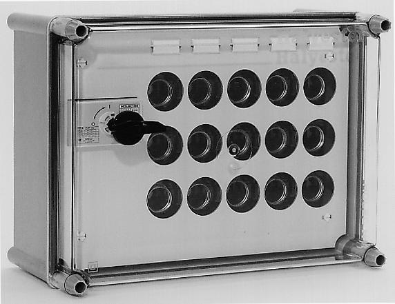
5 1. INTRODUCTION 1.1 Scope Halyester was designed as a modular low-voltage system for composing switchgear and controlgear assemblies for the distribution of electric power and motor control centres. The system is suited for indoor and outdoor installation and based on the principle of total insulation in accordance with standard IEC This ensures maximum operator safety. The outstanding mechanical and electrical characteristics of the plastic boxes give the Halyester system a long service life, even under the most prevalent arduous operating conditions. Halyester is extensively used in refineries, chemical plants and heavy industry. Thanks to its compact and modular design, the Halyester system is also eminently suited for being used in office buildings, greenhouses, department stores and factories. In addition, the separate boxes accommodating a wide variety of electrical switchgear and controlgear assemblies are a perfect enclosure for being used in relatively restricted places. Separate operating areas or buildings are no longer necessary because the Halyester system provides high operator safety and can be arranged outdoors. 1.2 Characteristics The boxes and assembling accessories are made from glass mat reinforced polyester; the covers are made from transparent or non-transparent UV-resistant polycarbonate. The features of the plastics used are: high impact strength self-extinguishing non-hygroscopic resistant to all weather conditions resistant to tracking immune to large temperature variations low weight easy to machine UV-resistant 1-2 Introduction
6 1.3 General system description Halyester switchgear and controlgear assemblies are designed as movable or stationary systems for indoor and outdoor installation. The ambient temperature may vary between + 70 C and - 25 C. In the case of outdoor installation it is advised to protect the assembly against direct sunlight and rainfall under extreme conditions. Boxes The Halyester system comprises assembled boxes from heat-resistant glass fibre reinforced polyester, with covers from polycarbonate. The system is made up of 10 differently sized boxes. Each box has a removable cover which is provided with locking screws which can be tightened either with a screw driver or manually. Manual locking screws are used for boxes which are adequately protected against contact with live parts which are allowed to be operated by non-technical personnel. According to the international IEC standard, low-voltage Halyester switchgear and controlgear assemblies may be used in places that are accessible to non-technical personnel. Busbar systems The main busbars are made from electrolytic copper ECu57 F25. The busbars are supported by glass fibre reinforced polyester busbar supports. All end caps, end covers and cable entry covers are provided with seamless polyurethane foam sealing end cover / cable entry cover busbar support end cap intermediate coupling piece casing cover flange for increasing depth cable sealing box segmented cable sealing box 8 9 Introduction 1-3
7 2. BOXES 2.1 Box overview Box accessories Box fittings flanges for increasing depth locking and sealing mounting plates for installing equipment press-in nuts for fixing equipment condensate discharge and ventilation Range of products Overview of busbar boxes Dimensions 2-24 Boxes 2-1
8 2. BOXES 2.1 Box overview box type weight K kg K kg K 434 with flange for increasing depth 2.5 kg 3.7 kg 2-2 Boxes
9 box type weight K kg K kg K 463 with flange for increasing depth 3.5 kg 5.0 kg Boxes 2-3
10 box type weight K 464 with flange for increasing depth 5.5 kg 7.2kg K 466 with flange for increasing depth 7.0 kg 11.0 kg 2-4 Boxes
11 box type weight K kg K kg Boxes 2-5


12 2.2 Box accessories Intermediate coupling pieces For interconnecting boxes with openings 2, 3 or 4. Busbar supports, end caps The busbar supports do not only serve as a busbar carrier but also as a connecting piece between two busbar boxes. They are provided with sealing and come with four coupling bolts and nuts. The bolt heads are insulated. The end caps for sealing the busbar compartment sides consist of a cap and busbar support. They are supplied with fastener material. End covers and cable entry covers The end cover is available in two models: for fastening from the inside; for fastening from the outside; The cable entry covers (only suited for outside fastening) come with knockouts.all end covers and cable entry covers have sealings and are suited for openings 2, 3 or Boxes


 having")

13 Covers and locking screws All covers are provided with sealing. The cover locking screws are suited for wire or band sealing and available for hand or tool operation. The locking screws may come with a hinge pin. Plastic nut For locking screws with hinge pin. Flanges for increasing depth Type KB 434, 463, 464 and 466 casings can be equipped with one or more flanges for increasing depth to obtain a larger mounting depth. The flanges for increasing depth come with sealing and fastener material. Cable sealing boxes The cable sealing boxes suited for openings 3 or 4 are available in two models: blank or with opening(s) having one or more rubber grommets; including sealing and complete with fastener material segmented and complete with segmented cable clamps Cable glands Plastic cable glands for cable entry come in 10 models (sizes Pg 7 thru Pg48). Segmented adaptor ring For segmented cable entries having a 40mm passage. Boxes 2-7


14 Press-in nut / self-tapping screws For fixing equipment to plastic base plate. base grondplaat plate Vent valve For box ventilation. Drain valve To be fitted at the lowest point in the box. Hinged operating windows For cover mounting to allow fast and easy operation of MCBs, RCCBs, RCBOs, etc. 2-8 Boxes

15 2.3 Box fittings Flanges for increasing depth The flanges for increasing depth, just like the casings, are moulded from glass fibre reinforced polyester. The flanges come with packing and captive locking screws suited for screwdriver tightening. Flanges for increasing depth are available for the Halyester boxes listed in table 2.1 below. This table specifies the flange for increasing depth per box type and the associated effective mounting depth.if necessary, several flanges can be fitted. Table 2.1: Flanges for increasing depth Box Flange for increasing Increasing depth type depth type in mm K 434 KR K 463 KR K 464 KR K 466 KR Flanges for increasing depth Boxes 2-9

, both with and without hinge pin.")


16 2.3.2 Locking and sealing Locking Locking screws suited for hand or tool operation are available for securing covers to casings of the Halyester system.both models are also available in a hinged configuration. Casings with one or more flanges for increasing depth can be provided with covers suited for locking screws (manual or screwdriver models), both with and without hinge pin. The screws to be used for flanges for increasing depth and the normal locking screws differ in that the hinge pin of the former ones has been shortened from abt. 85 mm to abt. 60 mm, because the casings are deeper than the flanges for increasing depth. To obtain a proper sealing between the cover and casing or flange for increasing depth, the locking screws must at least be torqued to 1.6 Nm. The different configurations and the fixation of the locking screws are shown below. Manual and screwdriver models 2 1 If a hinged locking screw is used,first fit the plastic nut 1 and then tighten the locking screw 2 Manual and screwdriver models with hinge pin Manual and screw driver models with hinge pin for raising frame Attach the casing to the wall or flange before fitting the locking screws 2-10 Boxes
17 Sealing Wire and band seals can be used on boxes not to be accessed, say for kwh measurement. 18 mm 2 mm Wire sealing Band sealing Boxes 2-11
18 2.3.3 Mounting plates for installing equipment The mounting plates for building equipment into Halyester boxes are made from plastic. They are secured to the bottom of the casing by means of cheese head screws (M6 x 10). Halyester boxes upwards of type K434 can be provided with more than one mounting plate. Table 2.2 shows the various options. For fitting and feeding through earth terminals, it is possible to fit an earth strip at the bottom left and top left holes of the mounting plate. Table 2.2: Scope of application of the mounting plates Mounting plate Dimensions Quantity In box type L x W (mm) type KG x K K 433 KG x K K K 434 KG x K K 486 KG x K 442 KG x K K 484 Type KG 466 mounting plate KG x K 463 KG x K K 486 KG x K 466 KG x K 484 KG x K Boxes
19 2.3.4 Press-in nuts for fixing equipment As already described, the mounting plate is fitted in the box for the fixation of equipment. To allow the equipment to be secured to the mounting plate, press-in nuts with M4 thru M12 metric thread are fitted into the plastic mounting plate, as shown in the figure below. Since the press-in nuts have a knurled rim, they are fixed into the mounting plate. The holes to be drilled for the various press-in nuts are listed in table 2.3. Light equipment can be secured direct to the mounting plate, using M4 screws instead of press-in nuts The holes to be drilled for the M4 screws have a diameter of mm Table 2.3: Holes for press-in nuts Internal thread of press-in nuts Holes to be drilled (mm) 0 M4 Ø M5 Ø M6 Ø M8 Ø M10 Ø M12 Ø Boxes 2-13
20 2.3.5 Condensate discharge and ventilation Drain valve If a Halyester box or a combination of boxes is arranged in a damp room, it is recommended to fit a drain valve at the bottom of the box, see figure bottom left. This valve cannot be dismounted from the outside. The shape of the plastic drain valve prevents foreign objects from being inserted into the box. Insects cannot enter the box via the valve either. To install the drain valve, it is necessary to drill a 23mm hole into the casing bottom. Vent valves To prevent condensation, 2 vent valves can be fitted together with the drain valve. These valves, however, are only required in the case of large temperature variations. The plastic vent valve has a little fine-mesh grate, preventing foreign objects or insects from entering. To ensure proper venting, two vent valves must be fitted per panel or box, one as high as possible in the side wall of the box or panel and one as low as possible in the opposite side. If there is no space for mounting the vent valves in the side walls of the boxes due to the compact design, they can also be fitted in the rear wall of the casings without any problem. Each vent valve must have two holes to allow mounting in the boxes, as shown below. The boxes complete with a drain valve and a vent valve meet IP mm Fixation of drain valve Fixation of vent valve 2-14 Boxes


21 Halyester manual 2.4 Range of products 415 V switch boxes Selection from Duco switch-disconnectors: 40 A 63 A IP V switch boxes Selection from Dumeco switch-disconnectors: 125 A 160 A 250 A 400 A 630 A 1000 A IP56 for feeder panels in TN-S and TN-C current systems selection from Dumeco switch-disconnectors: 1000 A 1250 A 1600 A IP56 for feeder panels in TN-S and TN-C current systems selection from Aeromat circuit breakers: 1000 A 1250 A 1600 A IP2X Terminal boxes terminal box 800 A IP66 Boxes 2-15


22 415 V switch-fuse boxes selection from Duco switch-disconnectors: 40 A 63 A IP V switch-fuse boxes selection from Dumeco switch-disconnectors: 63 A 125 A IP56 selection from Dumeco switch-disconnectors: 160 A 250 A 400 A 630 A IP56 selection from Vemeco switch-disconnector-fuses:100a 160 A 250 A 400 A IP56 will be replaced with QSA switches in good time 2-16 Boxes


23 selection from QSA switch-disconnector-fuses: 63A 125A 160A 250 A 400 A IP V switch-fuse boxes selection from FSD fuse-switch-disconnectors: 160A 250A 400A IP66 Boxes 2-17


24 500 V fuse boxes selection from Isocoupe D-type fuse bases: 3 x 25 A 3 x 63 A IP V fuse boxes selection from Isodin blade contacts-type fuse bases: 3 x 160 A 2 x 3 x 160 A 3 x 250 A 3 x 400 A 3 x 630 A IP66 Measuring instrument boxes selection from box types: K 433 K 434 IP V power group distribution boxes selection from Isocoupe D-type fuse bases: 2 x 25 A 2 x 63 A 4 x 25 A 3 x 63 A 6 x 25 A 4 x 63 A 8 x 25 A 6 x 63 A 4 x 25 A + 3 x 63 A IP66 Boxes for kwh measurement IP Boxes


25 230 / 400 V lighting group distribution boxes selection from number of lighting groups: 2, 3, 6 or 9 IP / 400 V lighting group distribution boxes selection from number of lighting groups: 3, 6 or 8 IP / 400 V lighting group distribution boxes with main switch selection from number of lighting groups: 3, 4, 7 or 10 IP / 400 V power group distribution boxes with main switch selection from number of power groups: 3 or 5 IP / 400 V lighting and power group distribution boxes with main switch selection from number of lighting groups: power groups: IP56 Boxes 2-19


26 230 / 400 V lighting and power group distribution boxes with main switch (residual current circuit breaker without overcurrent protection ) selection from number of lighting groups: IP56 power groups: Distribution boxes for modular components suitable for expansion selection from box types: K 444 K 464 IP / 400 V switch boxes with type RSD rotary switches selection from number of switches: 6 x 25 A 12 x 25 A 18 x 25 A IP V switch boxes with Duco switch-disconnectors selection from number of switches: 2 x 40 A 2 x 63 A 4 x 40 A 3 x 63 A 6 x 40 A 4 x 63 A IP V switch boxes with Dumeco switch-disconnectors number of switches: 2 x 125 A IP Boxes


27 415 V V feeder boxes for side assembly selection from Duco switch-disconnectors: 40 A 63 A IP V feeder boxes for side assembly selection from Dumeco switch-disconnectors: 125 A 160 A 250 A IP V feeder boxes for side assembly with: Isocoupe D-type fuse bases selection from Duco switch-disconnectors: 40 A 63 A IP56 Busbar connection boxes for side assembly with 3-phase busbars, neutral busbar and earth busbar selection from box types: RG 433 RG 434 IP66 Branch strips L1, L2, L3, N for: switch boxes switch-fuse boxes fuse boxes Wiring sets L1, L2, L3, N, PE for: connections between busbar boxes and distribution boxes Boxes 2-21
28 2.5 Overview of busbar boxes R 432 / R 433 / R 434 / R 434 / R 434 / Boxes
29 R 463 / R 464 / Boxes 2-23
30 2.6 Dimensions K 432 K 433 K K 442 K 444 K 463 K 464 K 466 K 484 K Boxes
31 Box K Box K Boxes 2-25
32 Box K Box K Boxes
33 Box K Box K Boxes 2-27
34 Box K Box K Boxes
35 Box K Boxes 2-29
36 Box K Boxes
37 3. BOX ASSEMBLY 3.1 Assembly openings Punching of openings hand-operated punching machine marking-off templates for feed-through openings Box assembly sequence box assembly using intermediate coupling pieces end and cable entry covers Assembly sequence for busbar boxes busbar supports end caps coupling of main and auxiliary busbars coupling of busbar connection boxes and group distribution boxes branch of main and auxiliary busbars Busbar systems 3-17 Box assembly 3-1
38 3. BOX ASSEMBLY 3.1 Assembly openings For proper assembly, the boxes to be coupled must have identical feed-through openings. Shown below are the dimensions and number of feed-through openings punched in the boxes. opening 2 opening 3 opening 4 Figure 3.1: Overview of feed-through openings 3-2 Box assembly

39 3.2 Punching of openings Hand-operated punching machine Openings in the casings of Halyester boxes can be made in different ways. One of the options is punching, using the hand-operated punching machine described below. Punching machine description - height including removable handle 1150 mm, and without handle 470 mm - maximum width 390 mm - overall depth excluding handle 350 mm - weight 80 kg The frame plate has four 12mm dia. openings for fixation of the punching machine. The machine is equipped with a fixed punching tool for opening 2. The stop strip has 4 centring pins, allowing the required openings to be punched in all casings. Punching machine operation - place the casing (with the fixing holes for the cover) onto the centring pins under the punching machine - punch the four fixing holes in the casing by pulling the handle - the machine is suited for punching opening 2 in one go. Openings 3 and 4 require several punching operations. Figure 3.2: Hand-operated punching machine Box assembly 3-3

40 3.2.2 Marking-off templates for feedthrough openings For making openings in casings, not only a punching machine but also a saw can be used. The openings to be sawn out can be marked off by means of templates, which are available for openings 2, 3 and 4. Hand tools can be used to simply make openings in the casings which are easy to work on. Work instruction: Figure 3.3: Marking-off templates - place the template on the casing - mark off the openings to be sawn out along the inside of the template Figure 3.4: Marking off - drill 7mm dia. holes in the casing through the template drill bushes 1 and inside the template 2 before sawing out 1 2 Figure 3.5: Drilling 3-4 Box assembly
41 - remove the template and saw the opening in the casing along the marking-off line Figure 3.6: Sawing out openings - the saw cuts made in the template for openings 3 and 4 can be used as a size for sawing out the front post - this is necessary if the casing is provided with a cable sealing box Figure 3.7: Sawing out front posts Box assembly 3-5
42 3.3 Box assembly sequence Box assembly using intermediate coupling pieces Open intermediate coupling pieces For proper assembly, the boxes to be coupled must have identical feed-through openings. They can be coupled both horizontally and vertically. The open intermediate coupling pieces are available in three sizes: for openings 2, 3 and 4. Table 3.1: Overview of intermediate coupling pieces open blank f eed-through intermediate coupling intermediate coupling opening piece piece type type U 420 UB U 430 UB U 440 UB Blank intermediate coupling pieces In addition to the above open intermediate coupling pieces, also blank intermediate coupling pieces are available to ensure dust-tight feed-through of lines etc. They are fitted in the same way as the open intermediate coupling pieces. Type UB 420 for opening 2, type UB 430 for opening 3 and type UB 440 for opening 4. Mounting - mount the intermediate coupling piece with the marking towards the rear - fit the bolts with plastic head by tightening the nuts only Figure 3.8:Fitting of open intermediate coupling piece Figure 3.9:Fitting of blank intermediate coupling piece 3-6 Box assembly
43 3.3.2 End and cable entry covers Function End covers are applied to seal unused vertical and horizontal openings. They are available in three models: for mounting from the inside: type U for mounting from the outside, type UE cable entry covers with knockouts for fitting cable glands: type UE.../. In situations where it is advised not to open the box from the outside (for example, in the case of sealing), it is possible to use end covers which are fixed from the inside. Table 3.2: Overview of end covers opening end cover type 2 U 402 UE U 403 UE U 404 UE 404 Table 3.3: Overview of cable entry covers cable entry covers opening type knockouts type UE 402 / x Pg16 UE 402 / 4 2 x Pg x Pg29 UE 403 / x Pg16 4 x Pg x Pg29 UE 403 / x Pg29 / 42 UE 404 / x Pg16 6 x Pg x Pg29 UE 404 / x Pg29 / 42 Figure 3.10: End cover fixed from the inside 1 Figure 3.11: End cover fixed from the outside. Special clips are supplied for that purpose 1 Figure 3.12: Cable entry cover with knockouts Box assembly 3-7
44 3.4 Assembly sequence for busbar boxes Busbar supports Function Four types of busbar supports for different busbar sections are available for coupling busbar boxes in horizontal direction and for feeding through the main busbars without causing short circuits. There are openings for 3-phase busbars, a neutral busbar and an earth busbar. In addition, four insulated auxiliary busbars (6 x 6 mm) can be fitted. The busbar supports can be used for opening 3 only. The maximum support distance between two busbar supports is 360 mm in view of the short-circuit strength of the busbar system. Table 3.4: Busbar supports with associated busbar load and busbar sections busbar support supply L1, L2, L3 (PE)N*) PE type single-side central mm mm mm R 430/ A 500 A 15x 4 15x 4 15x 3 R 430/ A 800 A 15x 8 15x 4 15x 4 R 430/ A 1000 A 15x16 15x 8 15x 6 R 430/ A 1000 A 15x24 15x12 15x 6 R 430/ A 1600 A 2(15x24) 2(15x12) 2(15x6) *) If the section of the neutral conductor should be identical with that of the phase, it is possible to enlarge the opening. This adjustment has no consequences for the short-circuit strength. When using a double-busbar system, it is necessary to fit equalising busbars on both ends of the busbar system. With larger installations, every third box and every following third box - starting from the power supply - must be equipped with equalising busbars. PE L1 L2 L3 (PE)N PE L1 L2 L3 (PE)N PE L1 L2 auxiliary busbars Figure 3.13: Double-busbar system with equalising busbars L3 (PE)N Figure 3.14: Busbar support 3-8 Box assembly
45 Mounting - mount the busbar supports between the busbar boxes in such a way that the feed-through openings of the main busbars are located at the rear side. - fit the bolts with plastic head by tightening the nuts only. Figure 3.15: Busbar support mounting Box assembly 3-9
46 3.4.2 End caps Function End caps are used to close the busbar system. A complete end cap consists of a busbar support, a recessed end cover and fastener material. Mounting Fix the end cap from the busbar box, using hexagonal head bolts (M6 x 25) and flat washers. Just like the end covers, the end caps are provided with press-in nuts. Table 3.5: Overview of end caps with associated busbar sections end cap L1, L2, L3 (PE)N PE type mm mm mm UR 403/ 4 15x 4 15x 4 15x 3 UR 403/ 8 15x 8 15x 4 15x 4 UR 403/16 15x16 15x 8 15x 6 UR 403/24 15x24 15x12 15x 6 Busbar length The length of the main busbars can be determined on the basis of the following data: busbar length = length of the busbar compartment + 2 x 24 mm On either side the busbars extend 16.5 mm into the end caps, see figure This allows the main busbar to be coupled to the busbar box to be attached when the busbar system is extended. Figure 3.16: Distance between the busbars when mounting the end cap 3-10 Box assembly
47 3.4.3 Coupling of main and auxiliary busbars Main busbar coupling If main busbars must be coupled, one or more busbar couplings may be used. In determining the busbar length, it should be considered that for each coupling 6 mm space is required between the busbars to be coupled. The busbar coupling clamps consist of two clamping pieces and fastening screws. With type A 70/16 and A 70/24 clamps, pointed screws are also used to optimize the current transfer. The busbars are coupled at a distance of 16.5 mm from the busbar support, see figure main busbar busbar coupling clamp 15 x 3 mm 15 x 4 mm A 70 / 8 Table 3.6: Overview of busbar coupling clamps 15 x 6 mm 15 x 8 mm A 70 / 8 15 x 12 mm tightening torque 9 Nm 15 x 16 mm A 70 / 16 2 x (15 x 8 mm) 15 x 24 mm A 70 / 24 3 x (15 x 8 mm) 16.5 mm Figure 3.17: Minimum distance for busbar coupling Box assembly 3-11
48 Auxiliary busbar coupling When coupling auxiliary busbars, the same distance must considered as with main busbar coupling, i.e mm from the busbar support. The auxiliary busbars (6 x 6 mm) must be insulated with glass fibre sleeves in view of the limited ventilating path and creepage distance between auxiliary and branch busbars, if any. For coupling purposes, it is necessary to remove the insulation. The branch busbars must therefore be taken into consideration when determining the coupling location. To enable the main busbar couplings to be checked, they should be fitted to another side of the casing or in an adjacent box. Figure 3.18: Coupling clamp for auxiliary busbar 3-12 Box assembly
49 3.4.4 Coupling of busbar connection boxes and group distribution boxes Mounting All group distribution boxes accommodate 3-phase busbars, 1 neutral busbar and 1 earth busbar. The connection to these box busbars may take place at the side, top or bottom. To this end, there are threaded holes for terminal screws at the end of the busbars. To enable connection to the busbars, each busbar can be provided with a terminal having a 16 mm 2 or 35 mm 2 section. M = 4,5 Nm For connection to the power supply (single-side 160 A or central 250 A) there are type RG 433 and RG 434 busbar boxes accommodating 3- phase busbars, 1 neutral busbar and 1 earth busbar. The busbars are mounted in the boxes in such a way that they can be connected using type AA 400 or AM 400 branch terminals. These terminals are also used in type R busbar boxes. Coupling strips according to figure 3.19 must be fitted to allow busbars in group distribution boxes and busbar boxes to be coupled. Figure 3.19: Busbar coupling There are power supply boxes suitable for being mounted to the side of group distribution boxes. Box assembly 3-13
50 3.4.5 Branch of main and auxiliary busbars Main busbar branch A branch of the phase, neutral and earth busbar up to a thickness of 6 mm with a maximum branch of 25 x 7 comprises the following components: 1 washer AA spacing clip 2 hexagon socket head screws M6 2 flat washers When main busbars with a thickness of over 6 mm and a branch of at least 30 x 10 mm are involved, the busbar branch terminal will comprise the following components: 1 washer AA spacing clips 4 hexagon socket head screws M6 4 flat washers AA 400 AA Figure 3.20: Branch strip dimensions 1 Figure 3.21: Mounting of busbar branch 1 1 Figure 3.22: If there is no sub-branch, a clamping bracket 1 may be used for the purpose of mounting Figure 3.23: If there is a sub-branch with a cable < 10 mm 2, a clamping bracket 1 may be used for the purpose of mounting 3-14 Box assembly
51 The length of the hexagon socket head screws is determined by the thickness of the main busbar and branch strips, see table below. b a Please refer to chapter 8 when determining the sections of the main and branch busbars. The hexagon socket head screws for fixing the busbar branch terminals must be torqued to 9 Nm. The busbar branch terminals are suited for branching both strips and cables.7mm holes must be drilled in the branch strips. c b 15 main busbar branch strip Figure 3.24: Busbar branch terminal A large number of branch strips are available for being mounted between busbar systems and switch boxes, switch-fuse boxes and fuse boxes. Table 3.7: Busbar branches main busbar (a) branch strip (b) hexagonal socket head screw (c) M = 9 Nm 15 x 3 mm 15 x 4 mm 15 x 6 mm 7 mm max. M6 x x 8 mm 0-5 mm 5-15 mm M6 x 30 M6 x x 12 mm 15 x 16 mm 0-7 mm 7-15 mm M6 x 40 M6 x x 24 mm 0-7 mm 7-15 mm M6 x 50 M6 x 60 Box assembly 3-15
52 For a general overview of the available branch strips and wiring sets, please consult the relevant catalogue on low-voltage switchgear and controlgear assemblies. PE L1 L2 L3 (PE)N PE L1 L2 L3 (PE)N L1 L2 L3 N L1 L2 L3 N Figure 3.25: Busbar branch examples Threaded connections Standard branch strip sets are available for all boxes that are placed under or above the busbar boxes. Threaded connections are used between lighting/power group distribution boxes and the main busbar system. These are also available as standard sets in 3 current ratings. One side of the wiring sets comes with cable sockets, whereas the other side must be finished by the assembly department. All wires are black, whereas the neutral conductor and PE conductor must be marked blue and yellow/green respectively. Auxiliary current branch An auxiliary current branch terminal comprises the following components: 1 fixing brace 1 terminal strip 1 clamping screw 1 terminal screw M5 x 8 When using auxiliary current branch terminals, the insulation local to the auxiliary busbar must be removed. Figure 3.26: Auxiliary current branch terminal 3-16 Box assembly
53 3.5 Busbar systems Table 3.8: Busbar load in relation to busbar sections power supply busbar section single-side central L1, L2, L3 N*) PE PEN I n I n mm mm mm mm 315 A 500 A 15 x 4 15 x 4 15 x 3 15 x A 800 A 15 x 8 15 x 4 15 x 4 15 x A 1000 A 15 x x 8 15 x 6 15 x A 1000 A 15 x x x 6 15 x 12 *) If the section of the neutral conductor should be identical with that of the phase, it is possible to enlarge the opening. This adjustment has no consequences for the short-circuit strength. Table 3.9: Busbar branches cable, section in mm 2 strip, W x H (mm) temperature resistance of insulated wire 105 C I n ambient temperature 35 C ambient temperature 35 C L1,L2,L3 N PE PEN L1,L2,L3 N PE PEN 16 A 1,5 1,5 1, A 2,5 2,5 2, A A A A A A x2 1 ) 12x2 1 ) 12x2 1 ) 12x2 1 ) 160 A x3 1 ) 12x2 1 ) 12x2 1 ) 12x2 1 ) 200 A x2 12x2 1 ) 12x2 1 ) 12x2 1 ) 250 A x3 12x2 1 ) 12x2 1 ) 12x2 1 ) 315 A x4 12x3 1 ) 12x3 1 ) 12x3 1 ) 400 A x6 20x2 20x2 20x2 500 A x6 20x3 20x3 20x3 630 A x8 20x4 20x3 20x4 800 A 40x10 30x4 30x3 30x A 50x15 50x15 40x6 50x A 2x50x15 50x15 40x6 50x15 1) Given the section of the terminal bolts of switches etc., a 12mm strip width was chosen for practical reasons; however, 10 x 2 mm or 10 x 3 mm is already sufficient. Box assembly 3-17
54 4. SUPPLY MODULE ASSEMBLY 4.1 Supply modules with switch-disconnector A supply module for bottom connection with segmented cable sealing box without segmented cable sealing box A supply module for top connection A supply module for bottom connection A supply module for top connection A supply module for bottom connection A supply module for top connection Detail drawings of busbar connections and cable inlet Supply modules with circuit breaker A supply module, with 3 poles + N A supply module, with 4 poles A/1250 A supply module, with 3 poles + N A/1250 A supply module, with 4 poles A supply module, with 3 poles + N A supply module, with 4 poles Detail drawings of busbar connections and cable inlet 4-19 Supply module assembly 4-1
55 4 SUPPLY MODULE ASSEMBLY 4.1 Supply modules with switch-disconnector Introduction The Halyester system can also be equipped with a double-busbar system suited for a maximum 1600 A load if central supply is involved. The switch boxes come with top or bottom connection. With top connection, the terminal strips can be connected direct to copper busbars protruding through the wall from the low-voltage compartment. All models are available for TN - C or TN - S systems. *) *) TN - C = L1, L2, L3, PEN TN - S = PE, L1, L2, L3, N If the switchgear and controlgear assembly is used in a TN-C system, the opening marked (PE)N in the busbar support must be used for the PEN conductor. Mounting This chapter shows the detail drawings for mounting busbar connections and grommets. Equalising busbars for double-busbar system When using a double-busbar system, it is necessary to fit equalising busbars on both ends of the busbar system. With larger installations, every third box and every following third box - starting from the power supply - must be equipped with equalising busbars (see figure 3.13). 4-2 Supply module assembly
56 A supply module for bottom connection with single-busbar system (15 x 24 mm) in 270 mm high box with segmented cable sealing box for connection of multi-core cables see chapter 3 for busbar system data detail, see pages 4-10/4-11 A 1 busbar box 2 3 switch box (DMV 1000) maximum phase 3x185 mm 2 N 3x185 mm 2 PE 3x185 mm 2 terminal box segmented cable sealing box A section A - A Supply module assembly 4-3
57 without segmented cable sealing box with single-core cables through grommets see chapter 3 for busbar system data detail, see page 4-10/4-11 A 1 busbar box 2 3 switch box (DMV 1000) maximum 11x1x185 mm 2 11 terminal box aanzicht view CC A C section A - A 4-4 Supply module assembly
58 A supply module for top connection with single-busbar system (15 x 24 mm) in 270 mm high box see chapter 3 for busbar system data detail, see page 4-10 A switch box (DMV 1250) 7 4 busbar bux 5 A section A - A Supply module assembly 4-5
59 A supply module for bottom connection with double-busbar system (2x15 x 24 mm) in 540 mm high box see chapter 3 for busbar system data A detail, see pages 4-10/ busbar box 7 assembly montage sequence volgorde a b switch box (DMV 1250) b a a b 9 B B maximum 24x1x240 mm2 terminal box 11 A C section A - A 3poles + solid neutral opvulring 4mm shim4 mm section B - B view C 4-6 Supply module assembly
60 A supply module for top connection with double-busbar system (2 x15 x 24 mm) in 540 mm high box see chapter 3 for busbar system data detail, see page 4-10 A switch box (DMV1250) 7 busbar box 4 5 A section A - A Supply module assembly 4-7
61 A supply module for bottom connection with double-busbar system (2x15 x 24 mm) in 540 mm high box see chapter 3 for busbar system data detail, see page 4-10/4-11 A 4 5 busbar box 6 8 montage assembly sequence volgorde a b switch box (DMV1600) b a a b 10 B B maximum 24x1x240 mm2 terminal box 11 A 3 poles + solid neutral section A - A C 2 shims opvulplaten section B - B view C 4-8 Supply module assembly
62 A supply module for top connection with double-busbar system (2 x15 x 24 mm) in 540 mm high box see chapter 3 for busbar system data detail, see page 4-10 A switch box (DMV 1600) 8 6 busbar box 4 5 A section A -A Supply module assembly 4-9
63 4.1.7 Detail drawings of busbar connections and cable inlet M6 M12 M M6 4 M6 5 M6 6 M6 M10 M12 M16 9 Nm 28 Nm 40 Nm 60 Nm M16 M16 M Supply module assembly
64 M12 M6 M12 M16 9 Nm 40 Nm 60 Nm M12 9 M12 M M6 Supply module assembly 4-11
65 4.2 Supply modules with circuit breaker Introduction The Halyester system is also suited for accommodating circuit breakers for maximum loads of up to 1500 A if central supply is involved. Depending on the load, type Aeromat AE 1000-SS, AE 1250-SS and AE 1600-SS can be used. The different configurations are shown in this manual. The switch boxes complete with fixed part come with bottom connection. Circuit breakers are supplied separately because of their weight. The terminal box is suited for 6 x 1 x 240 mm 2 per phase or neutral. All models are available for TN - C or TN - S systems. *) *) TN - C = L1, L2, L3, PEN TN - S = PE, L1, L2, L3, N If the switchgear and controlgear assembly is used in a TN-C system, the opening marked (PE)N in the busbar support must be used for the PEN conductor. Mounting This chapter shows the detail drawings for mounting busbar connections and cable inlet. Equalising busbars for double-busbar system When using a double-busbar system, it is necessary to fit equalising busbars on both ends of the busbar system. With larger installations, every third box and every following third box - starting from the power supply - must be equipped with equalising busbars.. Important Do not transport pre-assembled circuit breakers in boxes 4-12 Supply module assembly
66 A supply module, with 3 poles + N with single-busbar system (15 x 24 mm) in 270 mm high box see chapter 3 for busbar system data detail, see pages 4-19/4-20 B 1 2 busbar box 4 5 e A f f f f A 6 d c b a switch box (AE 1000-SS) maximum 24x1x240 mm 2 7 terminal box B C doorsnede section B - B - B view aanzicht C C section doorsnede A - A - A assembly montagevolgorde sequence a b c d e f Supply module assembly 4-13
67 A supply module, with 4 poles with single-busbar system (15 x 24 mm) in 270 mm high box see chapter 3 for busbar system data detail, see pages 4-19/4-20 B 1 2 busbar box 4 e A f f f f A 6 d c b a switch box (AE 1000-SS) maximum 24x1x240 mm 2 7 terminal box B C doorsnede section B B - B- B view aanzicht C C doorsnede section A - A- A assembly montagevolgorde sequence a b c d e f 4-14 Supply module assembly
68 A/1250 A supply module, with 3 poles + N with double-busbar system (2 x 15 x 24 mm) in 540 mm high box see chapter 3 for busbar system data detail, see pages 4-19/4-20 B 1 2 busbar box 4 5 A f f f f A e 6 d c b a switch box (AE 1000-SS/AE 1250-SS) maximum 24x1x240 mm 2 7 terminal box B C section B - B doorsnede - B view aanzicht C C section doorsnede A - A - A assembly montagevolgorde sequence a b c d e f Supply module assembly 4-15
69 A/1250 A supply module, with 4 poles with double-busbar system (2 x15 x 24 mm) in 540 mm high box see chapter 3 for busbar system data detail, see pages 4-19/4-20 B 1 2 busbar box 4 e A f f f f A 6 d c b a switch box (AE 1000-SS/AE 1250-SS) maximum 24x1x240 mm 2 7 terminal box B C section doorsnede B - B - B view aanzicht C C section doorsnede A - A- A assembly montagevolgorde sequence a b c d e f 4-16 Supply module assembly
70 A supply module, with 3 poles + N with double-busbar system (2 x15 x 24 mm) in 540 mm high box see chapter 3 for busbar system data detail, see pages 4-19/4-20 B 1 2 busbar box A f f f f A e 6 d c b a switch box (AE 1600-SS) maximum 24x1x240 mm 2 7 terminal box B C section doorsnede B - B B - B view aanzicht C C doorsnede section A A - A- A assembly montagevolgorde sequence a b c d e f Supply module assembly 4-17
71 A supply module, with 4 poles with double-busbar system (2 x 15 x 24 mm) in 540 mm high box see chapter 3 for busbar system data detail, see pages 4-19/4-20 B busbar box 4 5 e A f f f f A 6 d c b a switch box (AE 1600-SS) maximum24x1x240 mm 2 7 terminal box B C doorsnede section B - B- B view aanzicht C C section doorsnede A - A - A assembly montagevolgorde sequence a b c d e f 4-18 Supply module assembly
72 4.2.7 Detail drawings of busbar connection and cable inlet 1 5 M6 M16 2 M8 M6 M16 3 M6 M12 M6 9 Nm M8 14 Nm M16 4 M12 M16 40 Nm 60 Nm M8 L1 L2 L3 N M L L L N L L L N L L L N L L L3-4 coding of strips Supply module assembly 4-19
73 6 M12 M L L L1-3 coding of strips 478-L L L L L L L L L2-3 M12 40 Nm Supply module assembly
74 5. CABLE SEALING BOXES 5.1 Plastic cable glands Cable sealing box Segmented cable sealing box Special configuration for top connection 5-8 Cable sealing boxes 5-1
75 5. CABLE SEALING BOXES 5.1 Plastic cable glands According to standard IEC plastic boxes are not allowed to be interconnected by conductive parts, in order to limit a possible fault voltage to the relevant box. Nor is it permitted to feed any conductive parts from the inside to the outside. This means that metal parts which have to be fed through the box, must be insulated on the inside or outside. That s why the Halyester product range includes plastic cable glands for cable diameters from 3.5 to 40 mm. Listed in the table below are the cable glands, associated cable diameters and holes to be drilled. The lock nut of a cable gland has the largest diameter. This diameter should be taken into account when fitting a cable gland in the casing or end cover. Table 5.1: Overview of cable glands size cable diameter drill type (mm) (mm) Pg 7 3, E Pg E 409 Pg E 411 Pg 13, E Figure 5.1: Exploded view of cable gland 1 cable gland follower 2 thrust washer 3 cable gland ring 4 cable gland housing 5 lock nuts 3 Pg E 416 Pg E 421 Pg E 429 Pg E 436 Pg E 442 Pg E Cable sealing boxes
76 5.2 Cable sealing box Type E 403 and E 404 cable sealing boxes Cable sealing boxes can be fitted to boxes with openings 3 and 4. They are available in blank configuration and with 60mm or 80mm dia. holes. These holes are provided with rubber grommets from which the diameter of the cable(s) to be fed through can be cut out. For this purpose, various nicks are made in the grommets, in line with the most prevalent cable diameters. Before the cable sealing box with the accompanying fastener material is fitted to the casing, the front post must be cut out of the casing which has markings for that purpose. The cable sealing boxes are provided with sealing and locking screws. Mounting - saw the front post from the casing at the markings (see chapter 3) - cut the rubber grommet to the correct size - fit the grommet around the cable - slide the bushing over the cable core and then connect the cores - fit the cable sealing box to the casing, using four hexagon head bolts M6x8 - place the rubber grommet in the cable sealing box Figure 5.3: Rubber grommet Table 5.2: Holes to be drilled in the cable sealing box for the grommet max. cable diameter drill application mm mm E 403/160 E404/360 E 403/ E 404/180 E 404/280 Figure 5.2: Mounting of cable sealing box Cable sealing boxes 5-3
77 Dimensions type B B E 167 opening 3 E E 403/ E 403/ B' M opening 4 E E 404/ E 404/ E 404/ E B Figure 5.4: Cable sealing box dimensions opening 3 opening 4 type type ø60 E 403 ø80 E 404 ø60 E 403 / 160 ø80 E 404 / E 403/ ø60 E 404 / E 404 / 360 Figure 5.5: Cable sealing box configurations 5-4 Cable sealing boxes
78 Top connection If the cable is fed from the top, silicone sealant must be applied at the front local to the saw notches. This is done to obtain a proper seal. Figure 5.6: Sealing of the cable sealing box Cable attachment For terminal boxes having a width of 270 mm 2 and 360 mm 2 there are braces to which cables can be fitted, using Pohl clamps or tyraps. The braces must be fitted with the fastening screws of the mounting plates. The height of the braces is such that the cables can be fastened at about the same height as the connection points of switches, fuse holders, etc. Figure 5.7: Fitting of brace for Pohl clamp or tyraps Cable sealing boxes 5-5
79 5.3 Segmented cable sealing box Type EG 403 and EG 404 segmented cable sealing boxes A maximum of two 60mm dia. cables can be fed through the segmented cable sealing box. The cable sealing boxes can be fitted under a box with opening 3. Type EG 404 cable sealing box for opening 4 is suited for three 60mm or two 80mm dia. cables. For the segmented cable sealing box with cable clip there are filling pieces reducing the inlet from 60 to 40 mm. In addition, the clips for the 60mm dia. cable can be provided with a segmented rubber ring, from which openings can be cut for cable diameters of and 55 mm. Mounting - saw the front post from the casing along the markings - fit the rear half of the cable sealing box to the casing, using the hexagon head bolts M6 x 16 supplied. - if the cable diameter is too small for the relevant clip, a filling piece can be fitted - if the cable size deviates from the size of the half clips or filling pieces, fill the cable clip with tape - fit the half cable clip at the front in such a way that at least a space of 0.5 mm remains between both half clips - complete the cable sealing box by fitting its front half by means of four cheese head screws (M5 x 25) and safety rings detail of band sealing 0-0.5mm Remark: Segmented cable sealing boxes can be provided with a wire or band seal. This requires the fastening screw (M5 x 25) to be replaced with a special seal screw and seal plate. Figure 5.8: Mounting of cable sealing box 5-6 Cable sealing boxes
80 Dimensions type A B C A opening 3 EG 403/ EG 403/ B opening 4 EG 404/ EG 404/ EG 404/ EG 404/ EG 404/ C Figure 5.9: Dimensions of segmented cable sealing box opening 3 opening 4 60 type 60 type 80 type EG 403/160 EG 404/160 EG 404/ EG 403/260 EG 404/260 EG 404/ EG 404/ Figure 5.10: Segmented cable sealing box configurations Cable sealing boxes 5-7
81 5.4 Special configuration for top connection Top connection caps If cables come from below and must be connected at the top in the switchgear and controlgear assembly, top connection caps can be used. A top connection cap can be provided with cable glands or a cable sealing box. If a cable sealing box is used in combination with a top connection cap, another opening must be made in the bottom of the casing. In this case, only type K 434 box can be used. The hexagon head bolts M6 for fixing the cap must have a 50mm minimum length and need not be provided with an insulated head because no voltage can be transferred from one box to the other. Because of the additional intermediate coupling piece, the fastener material for the cable sealing box must be about 16 mm longer than the fastener material supplied. When top connection caps are used, the depth of the assembly will increase, which implies that extended spacers must be fitted to the frame uprights in the case of floor/wall mounting. When the supporting frame is assembled, the uprights must be placed so that the top connection caps do not stand in the way. For assembly of the supporting frames please refer to chapter mmmin. Note!marking to the rear Figure 5.11: Top connection cap with cable sealing box Figure 5.12: Exploded view of top connection cap 5-8 Cable sealing boxes
82 Dimensions of openings in top connection cap Type K 433 box space for cable glands opening 3 87± 0.5 Type K 434 box for type E 403 or EG 403 cable sealing box opening 3 opening 3 87± ± 0.5 Type K 434 box space for cable glands opening 4 87± 0.5 Figure 5.13: Configurations Remark: For the dimensions of opening 3 and 4 please refer to chapter 3. Cable sealing boxes 5-9
83 6. FRAME MOUNTING 6.1 Wall mounting single boxes wall mounting for small combinations Floor / wall mounting Free-standing arrangement Extensions of wall frames wall frames for small combinations floor/wall frames and frames for free-standing arrangement 6-9 Frame mounting 6-1
84 6. FRAME MOUNTING 6.1 Wall mounting Single boxes Depending on their size, Halyester boxes have four or six holes for wall mounting. Mounting - mark off the holes to be drilled in the wall, using a pencil - drill 6mm dia. holes in the wall Figure 6.1: Wall mounting Boxes can also be mounted to a wall, using external fixing brackets. The advantage of this type of mounting is that completely assembled boxes (complete with cover) can be mounted to the wall. In addition, boxes with fixing brackets can be moved easily, for instance in the case of construction work. - remove the cover and any hinge pins - now fit the fixing bracket, using a cheese head screw (M6 x 16), at an angle of 45 to the bottom of the casing. Remark: When boxes with more than four fixing holes are involved, only the upper and lower holes can be provided with an ear. With coupled boxes, not all fixing holes can be provided with a fixing bracket. The fixing brackets come in sets of 4 pieces complete with fastening screws. Ø7 mm Figure 6.2: Mounting of fixing bracket 6-2 Frame mounting
85 6.1.2 Wall mounting for small combinations This mounting frame at least comprises two horizontal C sections, whose dimensions are shown in the figure below. Mounting - fit the C sections at the level of the upper box fixing holes - using the braces fitted to the ends of the C section, the assembly can be mounted to the wall. The required minimum length of the C sections corresponds with the length of the combination of boxes measured over the widest part of the installation. The largest bridging between two sections should not exceed 2x270 mm = 540 mm. If the combination length exceeds the maximum supporting distance, several C sections and/or various supporting braces must be fitted. Data on the fixing distances of the frame also apply to Halyester boxes with a normal contents. If the boxes are equipped with transformers or other heavy equipment, the supporting distances must be reduced, at customer s own discretion mm max. 540 mm max. Figure 6.3:Wall mounting of small combinations Frame mounting 6-3
86 - slide square nuts M6 into the C section; the actual number of nuts should correspond with the number of box fixing points on the section. square nuts Figure 6.4: C section with square nuts - fit the required number of filling pieces to the C section, when two adjoining fixing points are involved. filling piece - now fit the boxes with cheese head screws (M6 x 25) on the section, after the boxes have been interconnected. Figure 6.5: Mounting of filling piece - fit the braces. In this way, extensions are possible. Ø14 mm - now mount the combination of boxes to the wall. The braces with 14mm dia. holes provide sufficient clearance between fixing bolts M12 and the actual braces to mount the combination horizontally to the wall. Figure 6.6: Fixing brace at the corner of the box 6-4 Frame mounting
87 6.2 Floor / wall mounting Switchgear which is too heavy or too large for a supporting frame for wall mounting can be provided with a frame for floor/wall mounting. Uprights for a floor/wall frame are available in four heights: 1530 mm, 1800 mm, 2070 mm and 2340 mm. spacing bracket Ø14 mm The upright can be secured with a spacing bracket. If the distance between the rear side of the installation and the wall is too small, for instance because top connection caps are used, one or more spacing strips can be fitted for each upright (see figure 6.8). When using spacing strips, the distance between the wall and the rear side of the installation is approximately 200 mm. The number of uprights to be fitted depends on the length of the installation. The uprights are spaced at 1350 mm as a maximum and the C sections at 540 mm. 90 mm Mounting - level the uprights - anchor the uprights, both to the floor and to the wall (see figure 6.7) - fit the spacing bracket in the upper slotted hole, using the clamping bracket with which the upper C section is also fixed to the frame (see figure 6.9) To allow future extensions, the centre of the outer uprights is levelled with the outside of the installation. The frame upright in between can be placed both at the transition between two boxes and centrally behind a box, if top connection caps are used or if the symmetry of the assembly calls for such an arrangement. Ø 14 mm Figure 6.7: Mounting of uprights M6 53 mm Ø14 mm 110 mm Figure 6.8: Spacing strip at upright Frame mounting 6-5
88 The required C section length corresponds with the length of the installation, i.e. the sum of the busbar boxes measured across the widest part of the casing, or n x 90 mm. If the length of the controlgear exceeds the standard length of the C section (abt. 5 m), all sections to be coupled must be secured to the upright by one clamping bracket. M8x To allow future extensions, only half of the C section must be fitted to the outer uprights. 1 Mounting of boxes on a C section, using square nuts and a filling piece, is identical to wall frame mounting upright staander spacing afstandsbeugel bracket C C-profiel section clamping klembeugel bracket Figure 6.9: Floor/wall frame mounting 6-6 Frame mounting
89 6.3 Free-standing arrangement Switchgear and controlgear assemblies which cannot be mounted to or against a wall can be provided with a supporting frame for free-standing arrangement. This frame can also be used for installations in back-to-back arrangement and assemblies arranged in corners. In addition, it is possible to provide this frame with a sun/rain cover (see chapter 7). The frame standard for free-standing arrangement consists of two uprights which must be mounted back to back, using two spacers. Uprights with a length of 2340 mm require three spacers. A complete standard for free-standing arrangement comprises the following parts: 2 uprights (for floor/wall mounting) 2 or 3 spacers 8 or 12 hexagon head bolts M8x20 8 or 12 spring washers 8 or 12 flat washers 8 or 12 hexagon nuts M8 When spacers are fitted, it should be taken into account that no C sections must be secured at the place reserved for these spacers. Otherwise, the positioning of a frame for freestanding arrangement and the installation of controlgear to a frame do not differ from the mounting of a frame to the floor/wall. 310 mm Figure 6.10: Frame standard for free-standing arrangement Frame mounting 6-7
90 6.4 Wall frame extensions Wall frames for small combinations Wall frames can be extended both to the left and right. In addition, it is readily possible to extend an installation both in upward and downward direction. Mounting C sections are extended to the left and right as follows: coupling strip - determine the length of the sections to be extended; their length is identical to the width of the combination to be built on, measured across the widest part of the boxes Figure 6.11: C section extension - remove the square nuts (used to secure the fixing braces to the C sections) from the installation side to be extended - fit half of the coupling strip in the existing section, as shown in figure fit the fixing brace and the existing box to the coupling strip - extend the frame by sliding the extension section onto the coupling strips and fixing it For subsequent frame mounting please refer to the rules set out in this chapter. 6-8 Frame mounting
91 6.4.2 Floor/wall frames and frames for free-standing arrangement Frames for floor/wall mounting and free-standing arrangement can be extended at both sides of the installation. In this case the distance between the new frame uprights and the outer existing standard is not allowed to exceed 1350 mm either. The required C section length corresponds with the length of the extension, measured across the widest part of the busbar box(es). Figure 6.12: C sections bracketed to upright The new sections on the outer upright of the existing installation and the section already fitted are secured as follows by one clamping bracket: - loosen the hexagon bolt a little and slide the C section under the bracket. Then re-tighten the bolt. If the extension requires one or more sections to be mounted on the upright of the existing installation, the required clamping brackets and sections can be fitted in those places without C section. This is not only true of floor/wall frame extensions but also of free-standing frame extensions. Frame mounting 6-9
92 7. SPECIAL CONFIGURATIONS 7.1 Arrangement in corners Back-to-back arrangement Sun/rain cover 7-7 Special configurations 7-1
93 7. SPECIAL CONFIGURATIONS 7.1 Arrangement in corners If a wall in a particular room is too short for arrangement of a switchgear and controlgear assembly, the equipment can be arranged in a corner (recessed), using one or more angular busbar boxes. An angular busbar box combination comprises: 1 type KB 432 casing provided with a plastic feed-through plate and 1 type R 432 busbar box. Required for mounting the feed-through plate on the casing are: four threaded sleeves (from hexagon bolts M16) four countersunk cap screws (M6x20) The space required for a corner box when using various supporting structures is shown in the figure below. The main busbars are coupled in both boxes next to the type KB 432 casing. B 180 uprights staanders feed-through doorvoerplaat plate A KB 432 type of frame A B (mm) (mm) floor/wall free-standing 375min. 330 min. wall Figure 7.1: Corner arrangement 7-2 Special configurations
94 26±1 2.5±0.5 M M Figure 7.2: Type KB 432 casing with feed-through plate Figure 7.3: Threaded sleeve 12,5±0.5 68± ±0.5 68± ± ± ± ±0.5 42±0.5 34±0.5 42±0.5 8± b a ±0.5 40±0.5 44±0.5 98± ± ±0.5 a = for main busbars b = for auxiliary busbars 72± ± ±0.5 10±0.5 Ø7± ±1 Ø Figure 7.4: Feed-through plate for type KB 432 casing Special configurations 7-3
95 Interconnection busbar for main busbar 53±1 Interconnection busbar for auxiliary busbar 53± ±1 154± ±1 180±1 67±1 busbar dimensions in line with the busbar system used (see chapter 3) Figure 7.5: Mounting of interconnection busbars 7-4 Special configurations
96 7.2 Back-to-back arrangement With the switchgear and controlgear assembly in back-to-back arrangement, the busbar systems must be interconnected using two type K 433 and one type K 432 boxes. The bottom of the type K 433 boxes must have an opening 3. In view of the short-circuit strength the boxes in the side walls as well as in the relevant bottoms must be provided with a busbar support. To ensure a proper sealing between the interconnection boxes and the assembly, a type U 430 connecting piece is fitted to the bottom of the type K 433 boxes. The main busbars must be coupled in the interconnection boxes using busbar coupling clamps. For the dimensions of the coupling busbars please refer to table 7.1. In determining the required space, allowance must be made for any flanges for increasing depth, protruding handles etc. A back-to-back arrangement can only be realised by using a supporting structure for free-standing arrangement, see chapter 7. K 433 K 432 K mm Figure 7.6: Back-to-back arrangement of controlgear assembly with interconnection box Special configurations 7-5
97 opening 3 for size of opening 3 see chapter 3 94 ± 0.5 Figure 7.7: Type K 433 interconnection box with opening 3 in bottom B for dimensions see table A Figure 7.8: Coupling busbars for interconnection box Table 7.1: Overview of coupling rails load copper strip number destined for dimensions (mm) (mm) A A B x 4 8 L1,L2,L3, N x 3 2 PE x 8 6 L1,L2,L x 4 4 N en PE x 16 6 L1,L2,L x 8 4 N x 6 2 PE Special configurations
98 7.3 Sun/rain cover Types of arrangement To protect switchgear and controlgear assemblies from direct sun light and rain, it can be provided with a sun/rain cover. This cover is available in three versions: free-standing arrangement back-to-back arrangement floor/wall arrangement These arrangements are shown diagrammatically below. free-standing back-to-back floor/wall Figure 7.9: Sun/rain cover arrangements Parts for mounting the sun/rain cover come as a standard package with one frame standard. The corrugated plates have a 900mm working width and are available in 1000mm and 1300mm lengths. Free-standing arrangement A free-standing cover is assembled as follows: - fit the support strip to the inside of the up rights, using the hexagon head bolt (M8 x 25) in the upper slotted hole of the upright - if the upper slotted hole in the upright is also used to fit the C section to the upright, the support strip must be fixed by means of a hexagon head bolt and a clamping bracket - fix the C section (with the opening pointing downwards) to the support strip with U bracket, using two hexagon head bolts (M6x20). M8x25 U-bracket C section support strip M6x20 clamping bracket upright Figure 7.10: Fixation of C section Special configurations 7-7
99 - insert half of the coupling spindle into the ends of the C section that has been fitted. - interconnect the sections using bolts M8 x 10 - fit three supports per aluminium corrugated plate to the C sections, fix these supports with U brackets to the sections, using two hexagon bolts (M6x20) per bracket coupling spindle M8x10 M6x20 support Figure 7.11: Mounting of coupling spindle - fit the corrugated plates with sufficient over lap to the supports - mark off the fixing holes in line with the holes in the supports - drill the holes at the top of the corrugation - secure the plates using bolts M6x20 and sealing caps sealing caps M6x20 Figure 7.12: Mounting of corrugated plates min. Figure 7.13: Dimensions of free-standing arrangement 7-8 Special configurations
100 Back-to-back arrangement Sun/rain cover for switchgear and controlgear assembly in back-to-back arrangement is twice the cover for free-standing arrangement M6x20 - couple the supports back to back using hexagon bolts (M6x20) Figure 7.14: Back-to-back coupling of supports min Figure 7.15: Dimensions of back-to-back arrangement Special configurations 7-9
101 Figure 7.16: Back-to-back arrangement including mounting details 7-10 Special configurations
102 Floor / wall arrangement Assemblies with frame for floor/wall arrangement can also be equipped with a sun/rain cover This cover is mounted as follows: - fix the uprights 60 mm from the wall, measured from the centre of the fixing holes in the foot - fit the support strip between the spacer at th bottom of the upright and the wall - anchor the whole to the wall Further, the fitting and mounting procedure for the C sections, supports, corrugated plates etc. is identical to the one specified under free-standing arrangement. The height of a sun/rain cover depends on the controlgear assembly to be installed. It is advised to stick to the minimum heights shown in the drawings in view of the length of the operating personnel min. Figure 7.17: Dimensions of floor/wall arrangement Special configurations 7-11
103 8. TECHNICAL DATA 8.1 Technical specification characteristics of plastics used resistance to chemicals Loads and short-circuit strength of busbar systems Technical data of distribution transformers Tightening torques Standards and certificates 8-6 Technical data 8-1
104 8. TECHNICAL DATA 8.1 Technical specification Rated operational voltage max. U e 1000 V Rated insulation voltage max. U i 1000 V Rated impulse withstand voltage max. U imp 12 kv Rated current supply max A busbar system max A Rated short-time withstand current max. I cw 50 ka - 1s Rated peak withstand current max. I pk 110 ka Degree of protection to BS EN max. IP66 Type of protection total insulation Impact strength according to BS EN casings IK 09 covers IK 10 Ambient temperature -25 C C. Application Cable connection Operation Arrangement indoor or outdoor installation at the top and/or bottom at the front free-standing wall back-to-back Extension horizontal and vertical Standards BS EN EN IEC BS EN BS EN Certification KEMA-Keur 8-2 Technical data
105 8.1.1 Characteristics of plastics used characteristics testing procedure unit polycarbonate glasmatreinforced DIN other polyester*) mechanical tensile strength ASTM D638 N/mm E-modulus ASTM D638 kn/mm 2 2,3 9 flexural strength ASTM D790 N/mm notched impact strength kj/m thermal flammability class - UL94-94 V2 (1.5 mm) 94 V1 (2 mm) heat resistance VICAT B/ C Martens degree C - >142 operating temperature - UL764 C - >200 glow-wire test - IEC C/mm 850/ /1.0 physical water absorption 7708T2 - mg - 50 water absorption equilibrium - ASTM D570 % elektrical volume resistivity ASTM D527 ohm.cm >10 15 >10 12 surface resistance IEC 93 ohm.cm - >10 11 tracking resistance IEC 112 V/KC 250 >600 *) glass compound: 36% by weight, 60% by volume Resistance to chemicals chemicals polycarbonate glasmat reinforced polyester acetone %ammonia %ammonia vapour %liquid sodium hydroxyde - x acetic acid %hydrogen fluoride vapour + x 15 %potassium bisulphide vapour + + sodium sulphide + + glycerol, liquid + + mixture of 3 parts of propyl alcohol and 1 part of methyl benzene + + benzene - + toluene - x xylene - + dichloride ethylene - + synthetic oil = resistant; x = resistant (limited) ; - = non-resistant Technical data 8-3
106 8.2 Loads and short-circuit strength of busbar systems Busbar boxes load rail data* short-circuit strength dimensions without fuses with fuses single-side central (mm) short-time peak L N PE PEN withstand withstand I n I eff I cw I pk 315 A 500 A 500 A 800 A 630 A 1000 A 800 A 1000 A 1500 A 1600 A 15x4 12 ka s 24 ka 400 A 50 ka 15x4 15x3 15x4 12 ka s 24 ka 630 A 30 ka 15 ka s 30 ka 15x8 20 ka - 1 s 50 ka 630 A 50 ka 24 ka s 50 ka 15x4 15x4 15x4 12 ka s 24 ka 630 A 30 ka 15 ka s 30 ka 15x16 32 ka - 1 s 67 ka 630 A 50 ka 15x8 15x6 15x ka - 1 s 40 ka 630 A 30 ka 15x24 32 ka - 1 s 67 ka 630 A 50 ka 15x12 15x6 15x ka - 1 s 40,2 ka 630 A 30 ka 2(15x24) 50 ka - 1 s 110 ka 2(15x12) 2(15x6) 2(15x12) 30 ka - 1 s 66 ka * Maximum rail support distance : 360 mm Busbar connection boxes load busbar data short-circuit strength single - side central dimensions without fuses (mm) short-time withstand peak withstand L N PE I cw I pk 160 A 250 A 15x4 15x4 15x4 10 ka s 17 ka 8-4 Technical data


107 8.3 Technical data of distribution transformers rated rated short-circuit short-circuit output current current current (kva) at I n (A) I k (ka eff ) I k (ka eff ) 400 V U k = 4% U k = 6% ,5 9, Tightening torques For electrical connections hexagonal bolt connections, quality at least 5.6 thread diameter M 5 M 6 M 8 M 10 M 12 M 16 spanner width mm sw 10 sw 13 sw 17 sw 19 sw 24 tightening torque Nm hexagonal socket head bolt connections with large head, quality at least 8.8 thread diameter M 5 M 6 M 8 M 10 M 12 M 16 spanner width mm sw 4 sw 5 sw 6 sw 8 sw 10 tightening torque Nm hexagonal socket head bolt connections with small head, quality at least 8.8 thread diameter M 5 M 6 M 8 M 10 M 12 M 16 spanner width mm sw 4 sw 5 sw 6 sw 8 tightening torque Nm hexagonal socket head bolt connections without head, quality at least 8.8 thread diameter M 5 M 6 M 8 M 10 M 12 M 16 spanner width mm sw 4 sw 5 sw 6 sw 8 tightening torque Nm Technical data 8-5
108 8.5 Standards and certificates Standards The Halyester system meets the following standards: national: BS EN European: EN international: IEC The Halyester system can be used in TN-S, TN-C, TN-C-S and TT current systems. It is a TTA (Type-Tested-Assembly) BS EN BS EN BS EN Specification for: type-tested and partially type-tested assemblies Low-voltage switchgear and controlgear assemblies Specification for: Degrees of protection provided by enclosures (IP code) Degrees of protection provided by enclosures for electrical equipment against external mechanical impacts (IK code) Certificates KEMA-Keur 8-6 Technical data
109 9. ENCLOSURES 9.1 Test report Certificate EU declaration of conformity KEMA-Keur certificate Revision overview 9-9 Enclosures 9-1
110 9. ENCLOSURES 9.1 Test report Test report Test report number: Test report relating to low-voltage switchgear and controlgear assemblies according to BS EN , EN and IEC Make: System: Eaton Holec Halyester Assembled by: Date: Signature: Enclosure: 9-2 Enclosures
111 Test report Item to be tested Approved NA Remarks 1 Name plate 1.1 Visible 1.2 Type designation / identification number 2 Connections Conductors between main busbar systems and outgoing components 2.1 Strip connections: in line with Eaton Holec table 2.2 Section of wire connections: in line with Eaton Holec table If deviating dimensions have been used, they are shown in the relevant drawing(s) 3 Designation of conductors of main and auxiliary current paths 3.1 Numbers/letters 3.2 Colours 3.3 Symbols 4 Designation of protective conductor PE and neutral conductor 4.1 Via marking, colour, location 4.2 PEN designation on PEN conductor in the case of a TN-C system 5 Functional test 5.1 Necessary If so: 5.2 Mechanical actuating elements / interlocks etc. Enclosures 9-3
112 Test report Item to be tested Approved NA Remarks 6 Insulation test Tick applicable insulation test according to 6a or 6b. 6a High-voltage test (At Ui 690 V 2.5 kv 1 s) 6a.1 Switchgear switched on or 6a.2 Per current path component 6b Visual inspection 7 Protective conductors 7.1 Check on protective conductors and electrical conducting parts by means of inspection or measurement in accordance with IEC , art Creepage distances, clearances and clearances in air 8.1 In accordance with EN-IEC , table 14 and table 16 9 Terminals 9.1 Suited for: Copper Aluminium Copper and aluminium* * To be specified in drawing. 10 Short-circuit strength of busbar system* A 12 ka 0.5 s 24 ka peak A 20 ka 1 s 50 ka peak A 32 ka 1 s 67 ka peak A 32 ka 1 s 67 ka peak A 50 KA 1 s 67 ka peak * Tick busbar system used. 11 Thermal test 11.1 Temperature rise verification by extrapolation or test (in accordance with IEC , art ) 12 Degree of protection 12.1 IP degree 9-4 Enclosures
113 Test report 11 Remarks Enclosures 9-5

114 9.2 Certificate Certificate The undersigned, Name: Company: Registered office: declares that the low-voltage switchgear and controlgear assembly Make: System: Eaton Holec Halyester Type- designation: Identification Number: has been assembled in line with manufacturer s instructions and tested in accordance with the requirements set out in standard IEC This certificate is accompanied by a test report featuring: Test report number: Electrical characteristics: Rated operational voltage in V: Rated current in A: Short-circuit strength of busbar system: See test report, item 10 Degree of protection: IP 56 Date: Signature: Enclosure: Test report 9-6 Enclosures
 provided that it is installed, maintained and")
: 73 / 23 / EEC of 19 February 1973 (L 77) modified by 93 / 68 / EEC of 22 July 1993 (L 220) so called: Low Voltage Directive It is in conformity with the following harmonized standard(s)")
115 9.3 EU declaration of conformity Declaration of conformity DOC /E We, Eaton Electric N.V., Europalaan 202, 7550 AA Hengelo, The Netherlands declare that the product: Halyester, Switchgear and controlgear assemblies (including accessories) provided that it is installed, maintained and used in the application for which it is made, with respect of the professional practices relevant installation standards and manufacturers instructions, complies with the provisions of Council Directive(s): 73 / 23 / EEC of 19 February 1973 (L 77) modified by 93 / 68 / EEC of 22 July 1993 (L 220) so called: Low Voltage Directive It is in conformity with the following harmonized standard(s) or other normative document(s). Low voltage switchgear and controlgear assemblies Type-tested and partially type-tested assemblies COPY EN January 1994 S. Castelein Data of affixing marking: 95 Director Eaton Electric N.V. Enclosures 9-7

116 9.4 KEMA-Keur certificate 9-8 Enclosures
XL Distribution enclosures WORKSHOP SPECIFICATIONS
 800 Distribution enclosures WORKSHOP SPECIFICATIONS With its extensive ranges, the Legrand offer meets your quality standards and provides real freedom and simplicity of installation together with acknowledged
CABINETS AND ENCLOSURES. XL³ 400 and XL³ 800 GLOBAL SPECIALIST IN ELECTRICAL AND DIGITAL BUILDING INFRASTRUCTURES
 O S O O CABINETS AND ENCLOSURES XL³ 400 and XL³ 800 GLOBAL SPECIALIST IN ELECTRICAL AND DIGITAL BUILDING INFRASTRUCTURES II With its extensive ranges, the Legrand offer meets your quality standards and
ENYSTAR Load Centers up to 250 A
 PASSION FOR POWER. up to 250 A according to IEC 61439-3 for commercial and industrial buildings Download at www.hensel-electric.en made in GERMANY since 1931 up to 250 A according to IEC 61439-3 for commercial
Empty enclosures IEC 62208
 374 www.hensel-electric.de/en in accordance with for customized solutions and individual applications for example for low-voltage switchgear and controlgear assemblies i n accordance with the IEC 61439-series
workshop specifications Plexo³ IP 65 cabinets
 workshop specifications Plexo³ IP 65 THE GLOBL SPECILIST IN ELECTRICL ND DIGITL BUILDING INFRSTRUCTURES With their IP 65 weatherproof protection and optimised dimensions, Plexo³, from 2 to 4 x 18 modules,
NPS/003/010 - Technical Specification for 400V Assemblies (LVAC Boards) utilised in Major Substations
 utilised in Major Substations") Version:- 3.0 Date of Issue:- Dec 2013 Page 1 of 13 NPS/003/010 - Technical Specification for 400V Assemblies (LVAC Boards) utilised in Major Substations 1. Purpose This document is the technical specification
Version:- 3.0 Date of Issue:- Dec 2013 Page 1 of 13 NPS/003/010 - Technical Specification for 400V Assemblies (LVAC Boards) utilised in Major Substations 1. Purpose This document is the technical specification
photovoltaic NEW Safe product solutions conforming to standards for Industrial Electrical Power Distribution Systems with extended product range
 Professional Photovoltaic Distributors NEW with extended product range 10 11 Safe product solutions conforming to standards for photovoltaic plants Industrial Electrical Power Distribution Systems Solar
Commando Safetyswitch
 80 Commando Safetyswitch Commando Safetyswitches are manufactured from Polybutylene Terephthalate (PBT) for maximum impact resistance. The range offers a selection of IP54 and IP65 ratings to cover a variety
Features EN/IEC Applications
 PO Modular polyester boxes nsulated boxes Standards eatures ntro N/ 639- N/ 6059 N/ 608 pprovals - oxes with polyester cover: types 3, 3R,,, 6, 6P, and 3 - oxes with polycarbonate cover: types 3, 3R,,,
Operating Instructions
 Operating Instructions Terminal Box > 8150/1 > 8150/2 Contents 1 Contents 1 Contents...2 2 General Information...2 2.1 Manufacturer...2 2.2 Operating Instructions Information...2 3 Intended Use...2 4 Safety
MR - MEDIUM RATING A
 88 MR - MEDIUM RATING 160-1000A SECTION CONTENTS 90 General features 96 Advantages 100 Illustrated contents MR MEDIUM RATING 102 Trunking components 110 Feed units and end covers 113 Tap-off boxes 118
STANDARD SPECIFICATION FOR. LIGHTING AND DC DISTRIBUTION PANELS WITH MCBs DOCUMENT NO: 44LK-5100/E.02/011
 Page 1 of 6 STANDARD SPECIFICATION FOR LIGHTING AND DC DISTRIBUTION PANELS WITH MCBs Rev No. Issue Date Pages Rev Description Prepared By Checked By Approved By 0 15.07.2008 6 Issued for FEED MSJ VDV VDV
In-line Plug-in Design 3NJ6
 Contents Page - Outgoing Feeders General 6/2 Structure and Functions inclusive Forms of Internal Separation, Installation of Instruments 6/2 Plug-on Bus System 6/2 Cable Connection Compartment 6/2 Switch-disconnector-fuse
abb SafeLink SF 6 Insulated Ring Main Unit Installation and Operating Instructions Switchgear Division Auckland, New Zealand SLMIO ver 2.
 Installation and Operating Instructions Switchgear Division Auckland, New Zealand SLMIO ver 2.12 Product Overview ABB's type-tested ring main unit (RMU) is an SF 6 insulated RMU utilising the latest developments
8WH2 Spring-Loaded Terminals
 8WH2 Spring-Loaded Terminals /2 Introduction /3 General data on 8WH /7 8WH through-type terminals 1) /18 8WH hybrid through-type terminals 1) /21 8WH fuse terminals /23 8WH isolating blade terminals /25
3/2 Introduction. Unequipped Distribution Boards (Flat Pack) 3/6 8GK1 surface-mounting distribution boards
 3/6 8GK1 surface-mounting distribution boards") ALPHA 400 - DIN Wall-Mounted Distribution Boards /2 Introduction Unequipped Distribution Boards (Flat Pack) /6 8GK1 surface-mounting distribution boards Pre-Assembled Unequipped Distribution Boards /7
ALPHA 400 - DIN Wall-Mounted Distribution Boards /2 Introduction Unequipped Distribution Boards (Flat Pack) /6 8GK1 surface-mounting distribution boards Pre-Assembled Unequipped Distribution Boards /7
IVS Distribution System. IVS - Table of Contents
 IVS - Table of Contents Overview System characteristics IVS System description Sheet steel wall-mounted DB for residential & functional buildings - IP30 Sheet steel wall-mounted DB for industrial applications
Low-voltage switchgear MNS Light W. Installation, handling and operation. ABB LV Systems
 Low-voltage switchgear MNS Light W Installation, handling and operation ABB LV Systems MNS Light W switchgear is a flexible system that is primarily designed for motor control. The rated service voltage
Underfloor to desk 231
 Technical information Underfloor to desk 231 Series 507 Powertrack Series 507 Powertrack is an underfloor busbar system rated at 63Amp maximum. It is available in Standard or CE (Clean Earth) versions.
EQUIPMENT FOR CONNECTION OF A PHOTOVOLTAIC INSTALLATION (UP TO 5 KW)
") Catalogue photovoltaic installations 2005 EQUIPMENT FOR CONNECTION OF A PHOTOVOLTAIC INSTALLATION (UP TO 5 KW) "POSSIBILITY OF ASSEMBLY FOR BIDIRECTIONAL ELECTRONIC MONOPHASE METER FOR ALL VERSIONS". MODULAR
Catalogue photovoltaic installations 2005 EQUIPMENT FOR CONNECTION OF A PHOTOVOLTAIC INSTALLATION (UP TO 5 KW) "POSSIBILITY OF ASSEMBLY FOR BIDIRECTIONAL ELECTRONIC MONOPHASE METER FOR ALL VERSIONS". MODULAR
Power distribution components
 Industrial electronics Power distribution components Reliable, cost-effective, complete R England sv_001.fm Rittal power distribution components Bar centre distance (mm) Number of poles Busbar dimensions
31-SDMS-01 REV. 03 SPECIFICATIONS FOR
 31-SDMS-01 REV. 03 SPECIFICATIONS FOR LOW VOLTAGE DISTRIBUTION PANEL This specification is property of SEC and subject to change or modification without any notice CONTENTS Clauses: Page No. 1.0 SCOPE
DOMINO Series surface mounting IP55
 Series surface mounting IP55 SERIES CONSUMER UNITS SURFACE MOUNTING VERSION - IP55 REFERENCE STANDARDS International standard IEC 60670 (989) and the Modification (994) Part : General requirements for
8WH2 Spring-Loaded Terminals
 8WH2 Spring-Loaded Terminals /2 Introduction /3 General data on 8WH /7 8WH through-type terminals 1) /18 8WH hybrid through-type terminals 1) /21 8WH fuse terminals /23 8WH isolating blade terminals /25
Cellwatch Electrical Installation
 Tech20081110-1-1 Cellwatch Electrical Installation Critical Distances...2 Typical Layout...3 Typical ibmu Placement...4 Typical Control Unit Placement...5 Physical Mounting and Location - General...6 CU
Energy Supply Systems
 Energy Supply Systems MULTIPOLE CONDUCTOR RAIL 831 10-125 amps KAT0831-0001b-E 13 pole multipole conductor rail in 33 package distribution centres of the postal service (Post AG) 9 pole multipole conductor
xcomfort EWK Compact Distribution Boxes
 Product catalogue EWK Compact Distribution Boxes Release 2017-03 Energizing a world that demands more. We deliver: Electrical solutions that use less energy, improve power reliability and make the places
Electrak powertrack / underfloor busbar system
 design and installation n General installation notes Electrak powertrack is a compact system that can be installed in floor voids as low as 48 mm Feed units are provided with one or two 25 mm diameter
Molded-Plastic Distribution Systems
 Molded-Plastic Distribution Systems / Introduction ALPHA 8HP molded-plastic distribution systems /8 Empty enclosures / Modular installation devices /4 DIAZED/NEOZED fuse systems /7 NP fuse switch disconnectors
B kv Gas-insulated Substations
 72.5 145 kv Gas-insulated Substations The increasing demand for electrical power in cities and industrial centres requires the installation of a compact and efficient distribution and transmission network.
NS Feeder pillar up to 3200A
 NS Feeder pillar up to 3200A Advanced technology for low voltage, outdoor distribution Merlin Gerin Modicon Telemecanique Outdoor electrical distribution with advanced technology Merlin Gerin low voltage,
with Vacuum Circuit Breaker HAF
 M E T A L - C L A D S W I T C H G E A R Safety and Reliability with Vacuum Circuit Breaker HAF Flexible Design and Compact with Vacuum Circuit Breaker HVF Easy Installation and Maintenance We build a better
KAM A Lighting Busbar System KAP A Plug-in Busbar Distribution System
 25-32 A Lighting Busbar System 4-63 A Plug-in Busbar Distribution System / CONTENTS E-LINE / General 2-3 System 4 Technical Characteristics 5 Standard Busbars 6 Standard Elements 7 Tap Off Plugs 8 Standard
1 Product Description System Layout Safety Instructions Intended Use Installation... 3
 Order Number 0812xx- Contents 1 Product Description... 2 2 System Layout... 2 3 Safety Instructions... 3 4 Intended Use... 3 5 Installation... 3 5.1 Hanger Clamp... 3 5.2 Cutting of Conductor Rail... 4
Multipole Conductor Rail MultiLine Program 0831
 Multipole Conductor Rail MultiLine Program 0831 Contents Description / Technical Data Description....2 Technical Data....3 Conductor Rails Rails complete with pre-mounted Connector...4 Power Feeds....5
BETA Low-Voltage Circuit Protection
 BETA Low-Voltage Circuit Protection /2 Introduction Miniature Circuit Breakers /4 5SP and 5SY miniature circuit breakers / 5SJ6...-.KS miniature circuit breakers with plug-in terminal /21 5SY6 0 miniature
Explosion protected terminal boxes type, GHG 72.
 1 Technical data 1.1 Plastic terminal boxes GHG 721... ATX type examination certificate BVS 13 ATX 013 X Marking acc. to 94/9/G and standard ATX x (d e mb) II T5* -55 T amb +55 Gb x (d e mb) II T6* -55
MODE - Multiple Occupancy Distribution Equipment Selection guide for low voltage indoor distribution up to 500A
 MODE - Multiple Occupancy Distribution Equipment Selection guide for low voltage indoor distribution up to 500A MODE - Multiple Occupancy Distribution Equipment Contents 4 MODE range: introduction 5 MODE
Linear Luminaire for Fluorescent Lamps Series EXLUX 6401
 > As wall, ceiling and pendant light fitting or pole mounted light fitting > Version with 2 lamps: 18 W, 36 W and 58 W > Central locking > All-pole disconnection by means of an N/C switch when the lamp
OMNIA System OMNIA SYSTEM - IP55 FLUSH AND SURFACE MOUNTING MODULAR SYSTEM. t. 50
 OMNIA System OMNIA SYSTEM - IP55 FLUSH AND SURFACE MOUNTING MODULAR SYSTEM The flush mounting box, which is suitable for walled installations, can be combined both horizontally and vertically with any
Domae. The right solution for distribution boards
 Domae The right solution for distribution boards Guaranteed quality and adapted solutions Domae : SIRIM approved The quality marks prove product conformity to their reference standard. They guarantee:
Spec Sheet: IEC309 Switched Socket, Horizontal 16A. Part Number
 Spec Sheet: IEC309 Switched Socket, Horizontal 16A Part Numbers Part Number EU67HSS316 EU67HSS416 EU67HSS516 Description IEC309 16A 3 Pin switched socket IEC309 16A 4 Pin switched socket IEC309 16A 5 Pin
2018 Consultant s Handbook Division 26 Electrical 2413 Switchboards
 1 General 1.1 Switchboards shall be U.L. listed and labeled. 1.2 Each switchboard shall have its own main disconnecting means unless it is located in the same room as its source of origin. In most cases
XL³ 400 metal distribution cabinets, free-standing enclosures and cable compartments
 87045 LIMOGES Cedex Telephone : 05 55 06 87 87 Fax : 05 55 06 88 88 XL³ 400 metal distribution cabinets, free-standing Cat. No(s) : 20103/04/05/06/07/08/18/19/23/ CONTENTS PAGE 1. General characteristics...
RiLine mm system technology for the global market
 60 system technology for the global market 02 RiLine60 Busbar systems 3 and 4 pole Support + bars + contact hazard protection Flat copper bar system, see 276 in HB 33 PLS busbar system, see 278 in HB 33
Consists of. Date:17/02/2011 Page 1/8
 Consists of 470518 Qty. Product 4 1 DEFA Termina - interior heater with holder 1 1 DEFA Futura - time program controller/timer 3 1 DEFA MultiCharger 1203 - battery charger/relay 6 1 DEFA Extension cable
General. Main electric circuits Fuses compartment Operating mechanisms Cables connection compartment
 General The switchgear must be suitable for 36 kv rated voltage and specifically conceived for the secondary distribution substations in M.V. with either ring or radial type networks. The switchgear must
e n e r g i a HULANICKI BEDNAREK sp. z o.o. HABeR-M Switchgear system rated up to 1600A 1
 e n e r g i a HULANICKI BEDNAREK sp. z o.o. Switchgear system rated up to 1600A www.haberenergia.pl 1 Switchgear system rated up to 1600 A Low voltage switchgear system utilising moulded-case circuit-breakers
NXPLUS C Single busbar. Maintenance-free for lifetime
 NXPLUS C Single busbar Maintenance-free for lifetime Energy Distribution Welcome! Page 2 Content Overview Technical data Typicals Panel design Circuit-Breaker panel Busbar Operation Metering Low-voltage
Rated current In (A) Other electrical data. IEC 309 range. EN see 70 RT range IK
 Other electrical data. IEC 309 range. EN see 70 RT range IK") 44 and 67 IB standard horizontal and vertical socket-outlets Industrial-type socket-outlets conforming to IEC 309 Standard, with mechanical interlock consisting of a circuit breaker enabling the plug to
44 and 67 IB standard horizontal and vertical socket-outlets Industrial-type socket-outlets conforming to IEC 309 Standard, with mechanical interlock consisting of a circuit breaker enabling the plug to
COMMANDO. Commando offers a comprehensive range of industrial plugs, connectors, socket outlets, appliance inlets, Combi and Modular-Combi units.
 WIRING DEVICES COMMANDO RANGE INTRODUCTION Commando offers a comprehensive range of industrial plugs, connectors, socket outlets, appliance inlets, Combi and Modular-Combi units. The Commando range is
Residual Current Protective Devices / Arc Fault Detection Devices (AFDDs)
") Introduction Overview Devices Page Application Standards Used in / Personnel, material and fire protection, as well as protection against direct contact. SIGRES with active condensation protection for
Introduction Overview Devices Page Application Standards Used in / Personnel, material and fire protection, as well as protection against direct contact. SIGRES with active condensation protection for
KAP A Plug-in Busbar Distribution System IEC ME 04
 EAE Elektrik A.Ş. Akcaburgaz Mahallesi, 119. Sokak, No:1 341 Esenyurt-Istanbul-TURKEY Tel: +9 (212) 866 2 Fax: +9 (212) 886 24 2 www.eae.com.tr 2-32 A Lighting Busbar System Y A N D EN V E IT AL s ISO
adaptable, reliable underfloor power
 adaptable, POWERTRACK reliable adaptable, reliable underfloor power 6 THE INDUSTRY STANDARD IN UNDERFLOOR POWER Electrak powertrack / underfloor busbar is perfect for cavity floor installations. With minimal
Installation Accessories
 Installation Accessories Elektrostatische Aufladung vermeiden. Nur mit feuchtem Tuch säubern. Evitez lez charges electrotetiques Nettoyer unkjuement avec un chifion humide. Avold electrostatic charge.
Operating Instructions
 Operating Instructions Pendant Light Fitting > Contents 1 Contents 1 Contents...2 2 General Information...2 3 General Notes Regarding Safety...3 4 Intended Area of Application...4 5 Technical Data...5
Cable arrangement 15 Preparation for cable installation. 15 Installation of the cables 16 Finishing of the cable installation. 17 Examples.
 Transportation and storage.. 3 General. 3 Unpacking at installation site....... 3 Transfer of cubicles at installation site... 3 Weight.. 4 Temporary storage. 4 Erection at site 5 General. 5 The switchgear
4/ Kabeldon fusegear and cable distribution cabinets Pre-assembled distribution boards
 /1 2015 Kabeldon fusegear and cable distribution cabinets Pre-assembled distribution boards Content Pre-assembled distribution boards Pre-assembled distribution boards Metered public lighting pillars GBC
Rittal RiLine60. The fascinating 60 mm system of the future assembly-friendly, time-saving, individual and modular. including.
 Rittal RiLine60 including innovations 2007 The fascinating 60 system of the future assembly-friendly, time-saving, individual and modular R Rittal RiLine60 perfection in a 60 system Time-saving assembly,
Distribution Blocks & Bus-bar Solutions
 Distribution Blocks & Bus-bar Solutions Insulated Multi Laminate Flexible Copper Bus-bars Threaded Copper Bus-bars Solid Copper Bus-bars Bus-bar Insulators & Supports Insulated Flexible Copper Braided
BETA Switching Switches and Light Indicators
 Siemens AG 2008 BETA Switching /2 Product overview /3 5TE8 control switches / 5TE4 pushbuttons /2 5TE5 light indicators /5 5TE8 ON/OFF switches /22 5TE9 busbars /24 5TE switch disconnectors Siemens ET
NEW. Rittal RiLine60 UL 508. The fascinating 60 mm system of the future
 NEW Rittal RiLine60 UL 508 The fascinating 60 mm system of the future R Rittal RiLine60 UL 508 Perfection in a 60 mm system Time-saving assembly, versatile applications and individual modularity are the
GAE MCC Modular-C. Catalogue Standardized Motor Control Centres. PT Guna Era Manufaktura
 Modular-C\Standardized Motor Control Centres\ M600204.15 PT Guna Era Manufaktura Catalogue 2015 GAE MCC Modular-C Standardized Motor Control Centres General Definition Type-tested low-voltage switchgear
ype UP T Busplugs Low Voltage Switchboard Equipment
 Busplugs Type UP Low Voltage Switchboard Equipment Publication UP 2013 Since product improvement is a continuing policy, we reserve the right to change specifications without notice. Contents Descriptive
Emergency Light Fitting for Fluorescent Lamps Series 6009
 > As wall, ceiling and pendant light fitting or pole mounted light fitting > Version with 2 lamps: 18 W and 36 W > Central locking > All-pole disconnection via N/C switch when opening light fitting or
EWK Surface-mounted Field Distribution Boards, IP43
 VT94514 Degree of protection IP43, IK09 Protection class II, fully insulated 160 mm enclosure depth Complete with door and installation field for add-on devices Combined plug-type terminals for neutral
B kv T&D GAS INSULATED SWITCHGEAR
 GAS INSULATED SWITCHGEAR B 105 170 300 kv The increasing demand for electrical power in cities and industrial centers necessitates the installation of a compact and efficient distribution and transmission
Junction Boxes & Enclosures JBES and ECES Series: 316L Stainless Steel Enclosures Increased Safety
 JBES Series Medium Voltage 11 kv ECES Series Compliance Data: ATEX - IEC: ATEX IEC CE Ex e II Ex ia IIC; Ex ib IIC T6 to T4 Ex td A21 T80 C to T130 C Ex de IIC; Ex demb IIC Operating Temperatures: -50
Compact System NRGS 11-2 NRGS Original Installation Instructions English
 Compact System NRGS 11-2 NRGS 16-2 EN English Original Installation Instructions 810366-05 1 Contents Important Notes Page Usage for the intended purpose...4 Safety note...4 LV (Low Voltage) Directive
ACCESSORIES FOR SZE2 CABINETS
 ZPAS 143 DOORS Doors Intended for use instead of front solid door or rear panel. Maximum door opening angle: 120 Sheet steel textured powder paint, light grey (RAL 7035), stiffened profiles, brown smoked
MNS Light F. Low-voltage switchgear with fixed units. ABB LV Systems
 MNS Light F Low-voltage switchgear with fixed units ABB LV Systems Cubicle design MNS Light F switchgear is a flexible system with a large selection of cubicle variants that can be built together in optional
7 Lighting Technology
 7 Lighting Technology Light Fittings for Fluorescent Lamps Series EXLUX 6400 (Zones 2, 21 & 22) As pendant or pole-mounting fittings With electronic ballast For two-pin fluorescent lamps 1 or 2 lamp versions:
35-kV Safefront SuperWell Mini-Switch Source Isolated Pad-Mounted Switchgear 50 Amp (Max) Clip-Mounted Current Limiting Fuses
 Clip-Mounted Current Limiting Fuses") Page 1 2016 EPMR-35-311S-R2/ESW-CM9 Three Phase Two Ways per Phase 200 Amp 35 kv Class Eaton s CPS LRTPs 50 Amp (Max) 27 kv Clip-Mounted NX Fuse Provisions 21.1/36.6 kv Grounded Wye Max Design, 150 kv
Page 1 2016 EPMR-35-311S-R2/ESW-CM9 Three Phase Two Ways per Phase 200 Amp 35 kv Class Eaton s CPS LRTPs 50 Amp (Max) 27 kv Clip-Mounted NX Fuse Provisions 21.1/36.6 kv Grounded Wye Max Design, 150 kv
DATA SHEET 3PH-Battery-Backup-Distribution for 1x Sunny Island
 3PHBatteryBackupDistribution for 1x Sunny Island enwitecordernumber 10012549 Customerarticlenumber Type designation Match code Application Batteryinverter Grid structure BatteryBackupDistribution 1PH prepared
FAQ S. Main Switchboard Design Criteria. ENGINEERED SOLUTIONS FOR ALL YOUR SWITCHBOARD NEEDS
 FAQ S Main Switchboard Design Criteria h ENGINEERED SOLUTIONS FOR ALL YOUR SWITCHBOARD NEEDS www.electricalswitchboards.com.au Main switchboard Design criteria Q: What is the Australian standard for main
Product Data For FARNELL
 ae Product Data For FARNELL ae Uniset is / Varioset is ae EL ELECTRONIC KOMBI SYSTEM WALL MOUNTING Pole clamp For reliable, convenient fastening to round or square poles. For pole diameter/size:
INDEX Bustrunking System Standard & Specifications Technical Parameters Copper Aluminum Components
 INDEX Bustrunking System.. (1) Standard & Specifications.. (2) Technical Parameters Copper.. (3-4) Aluminum.. (5-6) Components Straight Length (Feeder & Plug in type).. (7) Uniblock Joint, Edge Elbow &
Electrak power track underfloor power distribution systems
 4 www.electrak.co.uk Electrak power track underfloor power distribution systems Tel: 01207 503400 Fax: 01207 501799 Email: sales@electrak.co.uk Because of our policy of continuous improvement, Electrak
1 Product Description System Layout Safety Instructions Intended Use Installation... 3
 Part Number 0812xx- Contents 1 Product Description... 2 2 System Layout... 2 3 Safety Instructions... 3 4 Intended Use... 3 5 Installation... 3 5.1 Hanger Clamp... 3 5.2 Cutting of Conductor Rail... 4
MEDIUM VOLTAGE CE-B36 METAL CLAD SWITCHBOARDS. CE - B36 - C - en - REV
 CE - B36 - C - en - REV.00 2011.9 EDIU VOLTAGE EDIU VOLTAGE APPLICATION CE-B etal Clad switchboards are designed for use in public and industrial distribution system up to 36kV for the operation and protection
Spec Sheet: IEC309 Panel Socket, Angled 16A IP67. Part Number
 Spec Sheet: IEC309 Panel Socket, Angled 16A IP67 Part Numbers Part Number EU67SA316 EU67SA416 EU67SA516 Specification Description IEC309 16A 3 Pin panel socket, angled, IP67 IEC309 16A 4 Pin panel socket,
Relax... you re in safe hands CONSUMER UNITS / PRODUCT GUIDE.
 Relax... you re in safe hands CONSUMER UNITS / PRODUCT GUIDE Distributor : LEGRAND ELECTRIC LIMITED Great King Street North, Birmingham, B19 2LF Tel : 0870 608 9000 Fax : 0870 608 9004 CONSUMER UNIT BRO.10.05.??K
PANEL PANEL MOUNTING COMPONENTS
 PANEL PANEL MOUNTING COMPONENTS For conventional wiring, Wöhner offers a comprehensive range of panel components for fastening to a DIN rail or mounting plate. The fuses and associated connection technology
SWITCHGEAR FOR SERVICE UP TO 36kV (CABLE AND OVERHEAD CONDUCTOR CONNECTED)
") PRODUCED BY THE OPERATIONS DIRECTORATE OF ENERGY NETWORKS ASSOCIATION Issue 3 2012 SWITCHGEAR FOR SERVICE UP TO 36kV (CABLE AND OVERHEAD CONDUCTOR CONNECTED) www.energynetworks.org 2012 Energy Networks
PRODUCED BY THE OPERATIONS DIRECTORATE OF ENERGY NETWORKS ASSOCIATION Issue 3 2012 SWITCHGEAR FOR SERVICE UP TO 36kV (CABLE AND OVERHEAD CONDUCTOR CONNECTED) www.energynetworks.org 2012 Energy Networks
General characteristics
 Multipole Industrial Connectors General characteristics The multipole connectors for industrial purposes are used in electric and electronic machinery, robots, electric panels, control equipments and wherever
Prisma Plus G enclosures IP30, IP31, IP43 enclosures
 Prisma Plus G IP30, IP31, IP43 Prisma Plus G IP30, IP31, IP43 Presentation For safe and upgradeable electrical switchboards > Safety of people and property > Continuity of service > Optimization and upgradeability
Distribution boards. 68 Q-DIN Range
 Complete electric boards system for energy distribution in commercial, industrial and costrucion sites places. Available in both empty and wired version, in compliance with the IEC 61439 Standard: Versions
Unified requirements for systems with voltages above 1 kv up to 15 kv
 (1991) (Rev.1 May 2001) (Rev.2 July 2003) (Rev.3 Feb 2015) (Corr.1 June 2018) Unified requirements for systems with voltages above 1 kv up to 15 kv 1. General 1.1 Field of application The following requirements
125 to 4000 A. Functions. Conformity to standards. Approvals and certifications (1) General characteristics. Available on request
 General characteristics. Available on request") 125 to 4000 A sirco_353_a_1_cat sirco_296_a_1_cat sirco_300_b switches are manually operated or motorised multipolar load break switches. They break on and off under load and provide safety isolation for
125 to 4000 A sirco_353_a_1_cat sirco_296_a_1_cat sirco_300_b switches are manually operated or motorised multipolar load break switches. They break on and off under load and provide safety isolation for
Combiester Switch Disconnectors Airco Switches Railbox Fuse Switch Disconnectors Orion Minipol Maxipol
 Combiester Switch Disconnectors Airco Switches Railbox Fuse Switch Disconnectors Orion Minipol Maxipol THE CARIBBEAN EDITION DEGREE OF PROTECTION GENERAL MATERIALS DEGREE OF PROTECTION ENCLOSURE SERIES
Emergency Luminaire with LED Series EXLUX 6009/1 Version IIC
 > For use in hazardous areas with gas group IIC > Emergency luminaire for wall, ceiling, pendant or pole installation > Latest LED technology with a high luminous efficacy and a long service life > Central
MEDIUM VOLTAGE CE-B METAL CLAD SWITCHBOARDS. CE - B - C - en - REV
 MEDIUM VOLTAGE MEDIUM VOLTAGE APPLICATION CE-B Metal Clad switchboards are designed for use in public and industrial distribution system up to 24kV for the operation and protection of lines, generators,
XL 3 -N SimPly, EfficiEnt And SAfE. 3 - PHASE distribution boards up to 250 A
 XL 3 -N 125 250 SimPly, EfficiEnt And SAfE 3 - PHASE distribution boards up to 250 A the global specialist in ElEctricAl And digital building infrastructures Xl 3 -n Comprehensive and reliable range for
Emergency Luminaire with LED Series EXLUX 6409/1
 > Emergency luminaire for wall, ceiling, pendant or pole installation > Latest LED technology with a high luminous efficacy and a long service life > Central locking system > Weekly functional test > Annually
Consumer unit solutions to meet the requirements of the new 17th edition amendment 3 regulations
 MEMT Memera full metal consumer units and protective devices Consumer unit solutions to meet the requirements of the new 17th edition amendment 3 regulations Memera full metal consumer units and protective
Flush mounting enclosures. Pragma UP
 Flush mounting enclosures Presentation Flush mounting enclosures The appearance of this enclosure, its mechanical strength and its level of electrical safety make it a product fully suitable for residential
IP65/IP66 ABS/Polycarbonate Screw Lid Boxes
 IP65/IP66 ABS/Polycarbonate Screw Lid Boxes p Versatile, lightweight & durable p Choice of materials: polycarbonate for rugged applications or ABS as an economic alternative p IP protection for outdoor
Industrial Enclosures
 Industrial Enclosures Small enclosures from page 08 Polycarbonate enclosures PK... 0 Cast aluminium enclosures GA... 4 Terminal boxes KL... 6 E-ox E... 9 us enclosures G... 0 RiLAN Industrial IN... 4 Compact
SIVACON S4 Power Distribution Boards
 SIVACON S4 Power Distribution Boards Totally Integrated Power SIVACON Catalogue LV 56 Edition 2015 siemens.com/lowvoltage Related catalogs Contents Low-Voltage Power Distribution and LV 10 Electrical Installation
Key features. DESIGNS: - Conservator type - Hermetically sealed
 Package Substations OTDS manufactures a large range of oil filled hermitically sealed and conservator type transformers to be used in conjunction with our package substations. We are able to utalise the