Load break switches. Load break switches for all your applications... Why choose a load break switch designed for photovoltaic applications?...
|
|
|
- Beverly Franklin
- 5 years ago
- Views:
Transcription
1


2 Load break switches Load break switches for all your applications Why choose a load break switch designed for photovoltaic applications? Load break switch selection guide Photovoltaic load break switches selection guide UL load break switches selection guide p. 18 p. 19 p. 20 p. 22 p. 24 Load break switches Specific applications SIRCO M/MV p. 26 SIDER p. 78 SIRCO SIRCO AC p. 44 SIDERMAT p. 94 new INOSYS LBS p. 66 SIRCO MOT AT p. 104 Load break switches: p. 172 SIRCO MC PV p. 114 SIRCO MV PV p. 126 SIRCO PV p. 132 new INOSYS LBS p. 150 SIRCO MOT PV p. 164 new INOSYS LBS p. 150 SIRCO MC PV UL 508I p. 174 new INOSYS LBS UL 98B DC & PV applications p. 182 SIRCO PV UL 98B p. 196 Find out more Enclosed devices SIRCO M UL 508 SIRCO M UL 98 p. 230 p. 220 p. 236 new INOSYS LBS UL 98 AC application p. 726 Special requests Contact your local sales office. General Catalogue

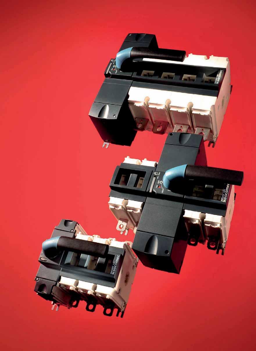
3 I I I I Load break switches for all your applications Load break switches Machine control, power distribution and photovoltaic installations Operating in the electrical breaking technology market since 1922, SOCOMEC is both a global leader and unrivalled benchmark reference. The SOCOMEC load break switches range is one of the largest on the market. INOSYS LBS is the latest range of load break switches incorporating tripping function especially designed and tested for most demanding applications. It completes the two lead product ranges ranges in this category: SIRCO M and SIRCO. If the three ranges INOSYS LBS, SIRCO and SIRCO M cover most needs, the complete range of SOCOMEC load break switches meets every application. A specific need? We have developed many customised solutions: switches with overrated neutral, high short circuit withstand, multipolar switches, earthing switches, motorised switches, etc. Whatever your application, you will find the right solution in the following pages! Discover all our products in the selection guides in the following pages. SOCOMEC load break switches in power distribution and machine control applications Local safety break Incoming section O O O O Machine control Red/yellow handle appli_312_a sircm_021_f_en Network Feeder output Motor SOCOMEC load break switches in photovoltaic applications Strings combiner box Junction box INOSYS LBS INOSYS LBS From 32 to 400 A up to 1500 V Up to 400 A, up to 1500 V DC Inverter connection box SIRCO PV or INOSYS LBS SIRCO load break switch up to 5000 A or FUSERBLOC fuse combination switch up to 1250 A SIRCO PV SIRCO PV From 400 to 2000 A, up to 1500 V DC Up to 400 A, up to 1500 V DC sircopv_028_d_1_gb_cat Double circuit switches permit increased numbers of inputs 18 General Catalogue


4 Why choose a load break switch designed for photovoltaic applications? range_574_a SIRCO MC PV, SIRCO PV and INOSYS LBS devices are available in IEC and UL versions. Safe operations To ensure electrical isolation during maintenance operations, or for emergency breaking to prevent a risk of fire or electrical shock, it is essential that dedicated photovoltaic switches are used. These devices must be installed at each functional level of the installation based on its architecture. In order to disconnect a direct current photovoltaic string, generator or UPS, only devices can: Isolate the associated high DC voltages, Guarantee safe onload disconnection several thousand times across the full range of DC currents linked to daily fluctuations in Devices designed for extreme conditions Socomec load break switches have been designed for industrial use. They are extremely robust, with casings made from glass fibrereinforced thermoset materials, bringing numerous benefits: Thermal stability, unlike some thermoplastics, Excellent resistance to high temperatures, Good electrical characteristics: Arc and insulation resistance, Good mechanical characteristics: Dimensional stability and rigidity over time. These benefits are particularly important in photovoltaic installations, where the temperature may be below 0 C or above 50 C. Backtoback design, an innovative solution The SOCOMEC range of photovoltaic load break switches enables simultaneous onload disconnection of two circuits using a single handle. Advantages Space saving: The overall width is the same as that of 3 or 4 pole devices. This enables significant savings, as compared to the use of two separate devices. Simple connection and integration. Increasing the voltage: Connecting the two devices in series allows onload Doubling the rating: By connecting the two devices in parallel. What are the standards that apply to photovoltaic installations? For installations Photovoltaic installations are governed by international standards such as IEC and UL. These standards provide the guidelines for commissioning a photovoltaic installation. Requirements for special installations or locations For breaking devices To date there is no specific IEC standard. Manufacturers must therefore refer to standard In the USA, the reference standard is UL98B. This testing, in particular concerning temperatures and resistance to electrical arcing. SIRCO PVs have been developed in compliance with both General Catalogue
5 Selection guide Load break switches Which application? Which function? Load break switches Machine control Applications SIRCO M 16 to 125 A Main switchboard Distribution panel Emergency load break Genset output Network coupling Local safety load break Machine control Photovoltaic load break Enclosed switches Functions 3/4 pole load break switch 6/8 pole load break switch 3/4 pole transfer switch (I0II) 3/4 pole transfer switch (IIIIII) Characteristics Operation Manual (rotating) Manual toggle Trippable Motorised Direct operation handle Front Side External operation handle Front Right side Left side Indication of breaking Positive break indication Visible contacts Switch body Modular (1) Please consult us. SIRCO MV 100 to 160 A p. 26 p General Catalogue
 (1) p. 396 p.")
6 Selection guide Load break switches Which operation handle? Which type of breaking? Which switch body? Power distribution new SIRCO 125 to 5000 A SIRCO AC INOSYS LBS 160 to 800 A SIDER 125 to 1600 A SIDERMAT 250 to 1800 A p. 44 p. 44 p. 66 p. 78 p. 94 (1) (1) p. 396 p. 396 p. 396 p. 396 p. 104 p. 104 General Catalogue
7 Selection guide Load break switches PV applications Which application? Which function? Load break switches Photovoltaics Applications SIRCO MC PV IEC 25 to 40 A SIRCO MV PV 63 to 80 A SIRCO PV IEC 100 to 3200 A SIRCO MOT PV 250 to 3200 A p. 114 p. 126 p. 132 p. 164 Main switchboard Distribution panel Emergency load break Genset output Network coupling Local safety load break Machine control Photovoltaic load break Fitted enclosures Functions 3/4 pole load break switch 6/8 pole load break switch 3/4 pole transfer switch (I0II) 3/4 pole transfer switch (IIIIII) Characteristics Operation Manual (rotating) Manual toggle Trippable Motorised Direct operation handle Front Side External operation handle Front Right side Left side Indication of breaking Positive break indication Visible contacts Switch body Modular (1) Please consult us. 22 General Catalogue
8 Selection guide Load break switches PV applications Which operation handle? Which type of breaking? Which switch body? DC and PV new new INOSYS LBS IEC without tripping function 160 to 1250 A INOSYS LBS IEC with tripping function 160 to 1250 A p. 150 p. 150 General Catalogue
9 Selection guide Load break switches UL products Which application? Which function? Load break switches Machine control Power distribution new Applications SIRCO M UL 508 SIRCO M UL 98 INOSYS LBS UL 98 with tripping function p. 220 p. 230 p. 236 Main switchboard Distribution panel Emergency load break Genset output Network coupling Local safety load break Machine control Photovoltaic load break Enclosed switches Surge protection Functions 3/4 pole load break switch 6/8 pole load break switch (1) 3/4 pole changeover switch (I0II) 3/4 pole changeover switch (IIIIII) Characteristics Operation Manual (rotating) Manual toggle Motorised Tripping function Direct operation handle Front External operation handle Front Right side Indication of breaking Positive break indication Visible contacts Switch body Modular 24 General Catalogue
10 Selection guide Load break switches UL products Which operation handle? Which type of breaking? Photovoltaic new DC and PV new SIRCO MC PV UL 508I SIRCO PV UL 98B 100 to 2000 INOSYS LBS UL 98B without tripping function INOSYS LBS UL 98B with tripping function p. 174 p. 196 p. 182 p. 182 General Catalogue


11 SIRCO M and MV Universal load break switches from 16 to 160 A The solution for Load break switches sircm_099_a > Main incoming load break > Distribution load break > Machine control > Local safety load break sircm_132_a 4 pole SIRCO MV direct operation Function 4 pole SIRCO M direct operation SIRCO M and MV are manually operated modulable and modular multipolar load break switches. They make and break under load conditions and provide safety isolation for any low voltage circuit, particularly for machine control circuits. Advantages Total integration The SIRCO M and MV fully integrate isolation, breaking and switching functions. Within a single product, SIRCO M offers front, right side or left side operation. Their highly functional design enables the product to be easily transformed from a load break switch to a changeover switch, offering a highly innovative modular solution for numerous applications. A wide range of accessories A single standard module, which can be complemented with a choice of accessories, offers a range of advantages: Simplicity when choosing the device. Flexibility to adapt to the most varied applications. Reduction in the cost of management and storage. Upgradeability Its wide range of accessories means that the SIRCO M can be upgraded even after it has been commissioned, enabling future requirements to be met. Through the use of accessories, SIRCO M can be transformed into multipolar load break changeover switches provide on load changeover switching between two sources or two low voltage power circuits, as well as their safety isolation. Compliance with major certifications and approvals The SIRCO M and MV range of load break switches have been designed, qualified and tested according to the criteria defined by standards IEC , UL508 and UL98. This process guarantees a high quality level for the product which is fully adapted to arduous operating environments. General characteristics Double break per pole. Mounting options: DIN rail, panel or modular panel with 45 mm front cut out. IP20 accessories and device. Severe utilisation categories (AC22 and AC23). Specific characteristics SIRCO M: Positive break indication. Contact point technology. Product can be mounted directly on the door or panel side; see "Door mounting kit" in the accessory section. SIRCO MV: Visible double breaking based on a sliding contact system (SIRCO type, see page Positive break indication. Strong points > Total integration > A wide range of accessories > Upgradeability > Compliance with major certifications and approvals > Specific characteristics Conformity to standards > IEC > Other standards available *See pages SIRCO UL and CSA range Approvals and certifications (1) (1) Product reference on request. Local safety enclosures > Fitted within a polycarbonate be used, for example, for onload breaking of a motor (AC23). * 26 General Catalogue


.")


12 SIRCO M and MV Universal load break switches from 16 to 160 A What you need to know SIRCO M SIRCO M can be operated in 3 different ways: SIRCO MV 3 operations are available: sircm_032_c_1_x_cat sircm_034_a_2_x_cat sircm_033_a_1_x_cat sircm_028_a_2_x_cat sircm_029_c_2_x_cat sircm_030_a_1_x_cat Complete switch body for toggle operation Direct front operation with handle External operation front, left side or right side The SIRCO M is a 3 pole load break switch which is available from 16 to 125 A. It can be combined with a switched 4 th pole, an unswitched neutral or PE pole and prebreak and signalling auxiliary contacts. The basic 3 pole device is available enclosed in a polycarbonate enclosure from 16 to 100 A page 726). From 16 to 125 A, through the wide range of available accessories, it is possible to convert a 3 pole load break switch into a 4, 6 or 8 pole load break switch or a 3/4 pole changeover switch. Through use of its door mounting kit, SIRCO M load break switches can be mounted on the panel door. sircm_173_a_1_cat Changeover switches I 0 II Direct front operation External right side operation External front and left side operation SIRCO MV can be ordered in 3 or 4 pole from 100 to 160 A. Two types of auxiliary contacts are available: Utype prebreak, Mtype for signalisation. General Catalogue
13 SIRCO M and MV Universal load break switches from 16 to 160 A References SIRCO M Rating (A) / Frame size No. of poles Complete switch body toggle operation Switch body Direct handle SIRCO M from 16 to 125 A Door interlocked external front and right side handle (8) External left side handle (8) Front external handle for changeover switches (8) Shaft for external front and side handle (8) 4 th pole 16 A / M1 3 P (1)(2)(3) A / M1 3 P (1)(2)(3) A / M1 32 A / M1 40 A / M1 3 P (1)(2)(3) S00 type I 0 Black M00 type IP Blue (4) Black Black IP65 IP65 3 P (1)(2)(3) Black 147A 5111 (4) IP (4) S0, S00 type Red S00 type I 0 Red/Yellow IP65 147B 5111 S00 type I 0 II I III II Black IP (4) Red/Yellow 150 mm IP P (1)(2)(3) (4) mm mm A / M2 3 P (1)(2)(3) A / M2 3 P (1)(2)(3) A / M3 125 A / M3 3 P (1)(2)(3) M01 type Blue S0 type I 0 Black IP (4) Black IP (4) 3 P (1)(2)(3) I III II Red/Yellow Black IP65 Red/Yellow IP IP65 148B (4) S0 type I 0 Black IP65 148A 5111 S00 type I 0 II Black IP (1) Front and side operation. (2) For a 6pole device in direct operation, order 2 x 3 pole device conversion kit (for external operation, add the shaft the handle). (3) For an 8pole device in direct operation, order 2 x 3 pole device 2 x 4th poles conversion kit (for external operation, add the shaft the handle). (4) Defeatable handle. (5) Top and bottom. (6) Delivered with a direct handle. (7) Delivered with a shaft. (8) Other handles are available. Please see accessory pages. 28 General Catalogue
14 SIRCO M and MV Universal load break switches from 16 to 160 A SIRCO M Rating (A) / Frame size No. of poles Complete switch body toggle operation Switch body SIRCO M from 16 to 125 A Unswitched neutral pole Unswitched protective earth module Auxiliary contact Terminal shrouds Door mounting kit 16 A / M1 3 P (1)(2)(3) 20 A / M1 3 P (1)(2)(3) 25 A / M1 32 A / M1 40 A / M1 63 A / M2 80 A / M2 3 P (1)(2)(3) 3 P (1)(2)(3) 3 P (1)(2)(3) 1 P P P (1)(2)(3) 1 P P M type 1 contact NO NC contact 2 NC P (5) 3 P (5) 1 P (5) 3 P (5) 3/4 P Complete protection IP2X (7) Compact design (7) 6/8 P Steel support (7) 100 A / M3 125 A / M3 1 P P (1)(2)(3) 1 P P (5) 3 P (5) 3/4 P Steel support (7) (1) Front and side operation. (2) For a 6pole device in direct operation, order 2 x 3 pole device conversion kit (for external operation, add the shaft the handle). (3) For an 8pole device in direct operation, order 2 x 3 pole device 2 x 4th poles conversion kit (for external operation, add the shaft the handle). (4) Defeatable handle. (5) Top and bottom. (6) Delivered with a direct handle. (7) Delivered with a shaft. (8) Other handles are available. Please see accessory pages. SIRCO MV Rating (A) No. of poles Switch body Direct handle SIRCO M from 100 to 160 A Door interlocked external front and right side handle (4) External left side handle (4) Shaft for external front and side handle (4) Auxiliary signal contact Prebreak auxiliary contact Terminal shrouds 3 P A 125 A 4 P P P P M0b type Blue (1) M0 type Blue S0 type I 0 Black IP (2) Black IP (2) Red/Yellow IP (2) S0 type I 0 Black IP65 149A 9111 Red/Yellow IP65 149B 9111 S0 type 150 mm mm mm M type 1 contact NO NC contact 2 NC U type 1 contact NC contact NO P (3) 4 P (3) 160 A 4 P (1) Standard. (2) Defeatable handle. (3) Top and bottom. (4) Other handles are available. Please see accessory pages. General Catalogue
 16 80 / M1 M2 Red M00 type 2299 5013 100 125 / M3 Blue M01 type 2299 5032 (1) (1) Standard.")
 / Frame size 16 80 / M1 M2 Type Switch Switch")
15 SIRCO M and MV Universal load break switches from 16 to 160 A Accessories Direct operation handle For SIRCO M Rating (A) / Frame size Handle colour Handle Reference / M1 M2 Blue M00 type (1) / M1 M2 Red M00 type / M3 Blue M01 type (1) (1) Standard. For SIRCO MV Rating (A) Handle colour Handle Reference Blue M0b type (1) Blue M0 type (1) Standard. M00 handle acces_347_a M0 handle M01 handle acces_344_a acces_352_a M0b handle acces_359_a External handle operation SIRCO M S000 type handle Rating (A) / Frame size / M1 M2 Type Switch Switch No. of poles 3/4 P 3/4 P Operation Front and side operation Front and side operation Handle colour Defeatable handle External IP Reference Black IP65 no Red/Yellow IP65 no Changeover 3/4 P Front Black IP65 no switches I 0 II / Changeover M1 M2 switches I 3/4 P Black IP65 no III II S00 type handle Rating (A) / No. of Handle Defeatable Frame size Type poles Operation colour External IP handle Reference Switch 3/4 P (1) Front and side operation Black IP55 yes Switch 3/4 P (1) Front and side operation Black IP65 yes / Switch 3/4 P M1 M2 Front and side operation Red/Yellow IP65 yes Switch 3/4 P Left side Black IP65 no 147A 5111 Switch 3/4 P Left side Red/Yellow IP65 no 147B 5111 Switch 6/8 P Front Black IP55 yes Switch 6/8 P Front Black IP65 yes M3 Switch 6/8 P Front Red/Yellow IP65 yes / M1 M2 M3 Changeover switches I 0 II Changeover switches I III II Changeover switches I 0 II Changeover switches I III II (1) Can also be used with 6 and 8 poles with front operation. 3/4 P Front Black IP65 yes /4 P Front Black IP65 yes /4 P Front Black IP65 yes /4 P Front Black IP65 yes S000 handle S00 handle acces_307_a_1_cat acces_341_a_1_cat 30 General Catalogue

 / No.")
 Padlockable in 3")
16 SIRCO M and MV Universal load break switches from 16 to 160 A External operation handle SIRCO M (continued) S0 type handle Rating (A) / Frame size Type No. of poles Operation Handle colour External IP Defeatable handle Reference Switch 3/4 P Front and side operation Black IP55 yes Switch 3/4 P Front and side operation Black IP65 yes Switch 3/4 P Front and side operation Red/Yellow IP65 yes / M3 Switch 3/4 P Left side Black IP65 no 148A 5111 Switch 3/4 P Left side Red/Yellow IP65 no 148B 5111 access_343_a S01 type handle Rating (A) / No. of Handle Defeatable Frame size Type poles Operation colour External IP handle Reference / Switch 3/4 P (2) Front and side operation Black IP65 yes M1 M3 Switch 3/4 P (2) Front and side operation Red/Yellow IP65 yes / M1 M3 Changeover switches I 0 II Changeover switches I 0 II Changeover switches I III II Changeover switches I III II (1) Padlockable in 3 positions. (2) Can also be used with 6 and 8 pole devices from 16 to 40 A. 3/4 P Front Black IP65 yes /4 P Front Black IP65 yes (1) 3/4 P Front Black IP65 yes /4 P Front Black IP65 yes (1) S0 handle S01 handle acces_304_a_1_cat External operation handle SIRCO MV S0 type handle Rating (A) Type No. of poles Switch 3/4 P Switch 3/4 P Switch 3/4 P Operation Front and side operation Front and side operation Front and side operation Handle colour External IP Defeatable handle Reference Black IP55 yes Black IP65 yes Red/Yellow IP65 yes Switch 3/4 P Left side Black IP65 no 149A Switch 3/4 P Left side Red/Yellow IP65 no 149B 9111 S1 type handle Rating (A) Type No. of poles Operation Handle colour External IP Defeatable handle Reference Switch 3/4 P Front Black IP55 yes Switch 3/4 P Front Black IP65 yes Switch 3/4 P Front Red/Yellow IP65 yes Switch 3/4 P Right side Black IP55 no Switch 3/4 P Right side Black IP65 no Switch 3/4 P Right side Red/Yellow IP65 no Switch 3/4 P Left side Black IP65 no 141A Switch 3/4 P Left side Red/Yellow IP65 no 141B 2111 S0 handle S1 Handle acces_343_a acces_284_a_2_cat General Catalogue

17 SIRCO M and MV Universal load break switches from 16 to 160 A Accessories (continued) Shaft for external handle SIRCO M 3/4 P Rating (A) / Frame size Handle type Type Length (mm) Reference S000 / S00 / S0 Switch 150 mm S000 / S00 / S0 Switch 200 mm / M1 M3 S000 / S00 / S0 Switch 320 mm S01 Switch 200 mm S01 Switch 320 mm S01 Switch 400 mm acces_346_a_1_cat SIRCO M 6/8 pole load break switch and 3/4 pole changeover switch Rating (A) Handle type Type Length (mm) Reference S000, S00 6/8 P and changeover switch 150 mm / M1...M2 S000, S00 6/8 P and changeover switch 200 mm S000, S00 6/8 P and changeover switch 320 mm S00 6/8 P and changeover switch 150 mm M3 S00 6/8 P and changeover switch 200 mm S00 6/8 P and changeover switch 320 mm S01 6/8 P 200 mm S01 6/8 P 320 mm / S01 6/8 P 400 mm M1 M2 S01 Changeover switch 200 mm S01 Changeover switch 320 mm S01 Changeover switch 400 mm S01 Changeover switch 150 mm M3 S01 Changeover switch 200 mm S01 Changeover switch 320 mm Standard lengths: 150 mm, 200 mm, 320 mm, 400 mm. Other lengths: Please consult us. For 3/4 pole switches, shaft extensions are for external front and side operation. For 6/8 pole switches and changeover switches, shaft extensions for front operation only. For SIRCO MV Rating (A) Handle type Type Length (mm) Reference S0 Switch 150 mm S0 Switch 200 mm S0 Switch 320 mm S1 Switch 200 mm S1 Switch 320 mm S1 Switch 400 mm Shaft guide for external operation To guide the shaft extension into the external handle. Description Handle type To be ordered in multiples of Reference Shaft guide S00 and S0 / S pieces Shaft guide S01 and S1 1 piece This accessory enables the handle to engage the extension shaft with a misalignment of up to 15 mm. Required for a shaft length over 320 mm. acces_260_a_2_cat 32 General Catalogue

18 SIRCO M and MV Universal load break switches from 16 to 160 A Additional pole for SIRCO M Switched fourth pole module Rating (A) / Frame size No. of poles Type Reference 16 / M1 1 P switched / M1 1 P switched / M1 1 P switched / M1 1 P switched / M1 1 P switched / M2 1 P switched / M2 1 P switched / M3 1 P switched / M3 1 P switched Adds one or two poles and transforms: a 3 pole SIRCO M into a 4 pole load break switch, a 6 pole SIRCO M into a 8 pole load break switch, a 3 pole SIRCO M into a 4 pole changeover switch. acces_322_a acces_323_a acces_324_a Neutral pole Rating (A) / Frame size No. of poles Type Reference / M1 1 P unswitched / M2 1 P unswitched / M3 1 P unswitched Transforms the 3pole switch into a 3pole solid neutral. 4 th pole Protective earth module N or PE Neutral pole N or PE Protective earth module Rating (A) / Frame size No. of poles Type Reference / M1 1 P unswitched / M2 1 P unswitched / M3 1 P unswitched Adds 1 protective earth module pole to the switchdisconnector. N or PE N or PE Additional pole configuration N or PE N or PE sircm_078_a_1_gb_cat Terminal shrouds Top and bottom protection against direct contact with the terminals or connection parts. Available in 1 or 3 pole versions for SIRCO M and in 3 or 4 pole versions for SIRCO MV. An opening on each terminal cover makes it possible to insert a temperature measurement probe. For SIRCO M Rating (A) / Frame size No. of poles Position Reference / M1 1 P top and bottom / M1 3 P top and bottom / M2 1 P top and bottom / M1 3 P top and bottom / M3 1 P top and bottom / M3 3 P top and bottom For SIRCO MV Rating (A) No. of poles Position Reference P top and bottom P top and bottom SIRCO MV 3P SIRCO M acces_327_a SIRCO MV acces_328_a SIRCO M acces_329_a acces_326_a General Catalogue
 / Frame size Number of AC Type of AC Reference 16 125 / M1.")
19 SIRCO M and MV Universal load break switches from 16 to 160 A Accessories (continued) M type auxiliary contacts Prebreak and signalisation of positions 0 and I by NONC or 2 NO auxiliary contacts. They allow to anticipate the switching of the main poles. They can be mounted on the left For SIRCO M Rating (A) / Frame size Number of AC Type of AC Reference / M1...M3 1 AC NO NC AC 2 NO For SIRCO MV Rating (A) Number of AC Type of AC Reference AC NO NC AC 2 NO Characteristics Operating current I e (A) 230 VAC Contact type Nominal current (A) AC13 AC15 NO NC Auxiliary contact configurations for SIRCO MV sircm_098_a_1_cat For SIRCO MV Rating (A) Number of AC Type of AC Reference AC NC AC NO Characteristics Max 4 auxiliary contacts (2 modules). Prebreak is not guaranteed on the SIRCO MV. Characteristics NONC auxiliary contacts: IP2 with front operation. 1. Maximum 2 "U" type auxiliary contacts. 2. Maximum 2 "M" type auxiliary contact modules. Operating current I e (A) Contact Nominal 250 VAC 400 VAC 24 VDC 48 VDC type current (A) AC15 AC15 DC13 DC13 NC NO U type M type Prebreak and signalisation by NO or NC auxiliary contact can be mounted on the device. Maximum 2 auxiliary contacts. Only available for SIRCO MV switches. acces_320_a Auxiliary contacts configurations for SIRCO M Max: 2 blocks / Max: 2 AC 2 NC NO NC Prebreak No Prebreak sircm_188_a_1_x_cat sircm_048_a_1_x_cat Conversion kit It must be ordered together with the handle for external control. This accessory enables the assembly of two 3 pole switches ( additional pole) in order to create : a 6 or 8 pole SIRCO M load break switch, a 3 or 4 pole SIRCO M changeover switch. Load break switches 6/8 P Rating (A) / Frame size Type Reference / M1 M2 6/8 P switch / M3 6/8 P switch Changeover switches I 0 II Rating (A) / Frame size Type Reference / M1 M2 Changeover switches I 0 II / M3 Changeover switches I 0 II General Catalogue SIRCO M changeover switches provide on load changeover switching between two sources or two low voltage power circuits, as well as their safety isolation (I 0 II); transfer without interruption of the supply is also possible (I III II). Changeover switches I III II Rating (A) / Frame size Type Reference / M1 M2 Changeover switches I III II / M3 Changeover switches I III II Conversion kit for 6 or 8 pole load break switches Conversion kit for changeover switches I 0 II Conversion kit for changeover switches I III II acces_348_a acces_350_a acces_49_a


 / Frame size Pack Reference 16 125 / M1 M3 20 pieces 2299 9409 This piece snaps into place directly on the front face")

 / Frame size Pack Reference 16 80 / M1 M2 40 pieces 2299 9909 DIN rail locking clip This locking clip prevents the")
20 SIRCO M and MV Universal load break switches from 16 to 160 A Door mounting kit (1) This kit enables a direct mounting of the switch on the door panel, on the right or left side of the panel. The connection clamps of the switch are always accessible. The external handle is quick and easy to install with the supplied internal locking nut mounted on the inside of the enclosure. 3 kits are available: one for complete protection IP2X one with compact design one in steel for 6/8 P and 100/125 A. For SIRCO M (1) Kit compatible with S00 type handle only. Rating (A) / Frame size No. of poles Description Reference 3/4 P Complete protection IP2X / M1 M2 3/4 P Compact version /8 P Metallic support /4 P Metallic support acces_330_a 3/4 poles acces_331_a acces_332_a Cap for side operation mounting This accessory enables the front face of the SIRCO M to be capped when the switch is side operated. 20 pieces supplied per pack. For SIRCO M Rating (A) / Frame size Pack Reference / M1 M3 20 pieces This piece snaps into place directly on the front face of the switch. 6/8 pole sircm_126_a_2_cat 6/8 pole joining accessory This accessory enables two 3/4 pole switches to be coupled in order to provide a 6 or 8 pole switch for external side operation. 40 pieces supplied per pack. For SIRCO M Rating (A) / Frame size Pack Reference / M1 M2 40 pieces DIN rail locking clip This locking clip prevents the SIRCO MV from sliding when DIN rail mounted. For SIRCO MV For multipole switches, please consult us. sircm_134_a_2_cat Rating (A) Type Reference Locking clip M Locking clip M acces_337_a Voltage sensing and power supply tap sensing or power cables. For SIRCO MV Rating (A) Pack Reference pieces This singlepole voltage sensing tap allows power terminal without reducing its connection capacity. acces_336_a General Catalogue
21 SIRCO M and MV Universal load break switches from 16 to 160 A Characteristics Characteristics according to IEC SIRCO M from 16 to 125 A Thermal current I th (40 C) 16 A 20 A 25 A 32 A 40 A 63 A 80 A 100 A 125 A Frame size M1 M1 M1 M1 M1 M2 M2 M3 M3 Rated insulation voltage U i (V) Rated impulse withstand voltage U imp (kv) Rated operational currents I e (A) Rated voltage Utilisation category A/B (1) A/B (1) A/B (1) A/B (1) A/B (1) A/B (1) A/B (1) A/B (1) A/B (1) 415 VAC AC20 A / AC20 B 16/16 20/20 25/25 32/32 40/40 63/63 80/80 100/ / VAC AC21 A / AC21 B 16/16 20/20 25/25 32/32 40/40 63/63 80/80 100/ / VAC AC22 A / AC22 B 16/16 20/20 25/25 32/32 40/40 63/63 80/80 100/ / VAC AC23 A / AC23 B 16/16 20/20 25/25 32/32 40/40 63/63 80/80 100/ / VAC AC20 A / AC20 B 16/16 20/20 25/25 32/32 40/40 63/63 80/80 100/ / VAC AC21 A / AC21 B 16/16 20/20 25/25 32/32 40/40 63/63 80/80 100/ / VAC AC22 A / AC22 B 16/16 20/20 25/25 32/32 40/40 63/63 80/80 100/ / VAC AC23 A / AC23 B 16/16 20/20 25/25 25/25 25/25 63/63 63/63 80/80 100/ VAC AC20 A / AC20 B 16/16 20/20 25/25 32/32 40/40 63/63 80/80 100/ / VAC AC21 A / AC21 B 16/16 20/20 25/25 32/32 40/40 63/63 80/80 100/ / VAC AC22 A / AC22 B 16/16 20/20 25/25 32/32 32/40 40/63 63/80 80/ / VAC AC23 A / AC23 B 16/16 20/20 25/25 25/25 25/25 40/40 40/40 63/63 63/ VDC DC20 A / DC20 B 16/16 20/20 25/25 32/32 40/40 63/63 80/80 100/ / VDC DC21 A / DC21 B 16/16 (2) 20/20 (2) 25/25 (2) 32/32 (2) 40/40 (2) 63/63 (2) 80/80 (2) 100/100 (2) 125/125 (2) 250 VDC DC20 A / DC20 B 16/16 20/20 25/25 32/32 40/40 63/63 80/80 100/ / VDC DC21 A / DC21 B 16/16 (3) 20/20 (3) 25/25 (3) 32/32 (3) 40/40 (3) 63/63 (3) 80/80 (3) 100/100 (3) 125/125 (3) 400 VDC DC20 A / DC20 B 16/16 20/20 25/25 32/32 40/40 63/63 80/80 100/ / VDC DC21 A / DC21 B 16/16 (4) 20/20 (4) 25/25 (4) 25/25 (4) 25/25 (4) 40/40 (4) 40/40 (4) 63/63 (4) 63/63 (4) Operational power in AC23 (kw) 400 VAC without prebreak AC(kW) (5) VAC without prebreak AC(kW) (5) VAC without prebreak AC(kW) (5) Fuse protected shortcircuit withstand (ka rms prospective) (6) Prospective shortcircuit current (ka rms) Associated fuse rating (A) Circuit breaker protected shortcircuit withstand with any circuit breaker that ensures tripping in less than 0.3s Rated shorttime withstand current 0.3s. I cw (ka rms) Shortcircuit capacity (without protection) Rated shorttime withstand current 1s. I cw (ka rms) Rated peak withstand current (ka peak) (6) Connection Tightening torque min/max (Nm) 2 / / / / / / / /4.4 4/4.4 Mechanical characteristics Durability (number of operating cycles) Operating effort 3 pole device (Nm) Operating effort 4 pole device (Nm) Weight of a 3 pole device (kg) Weight of a 4 pole device (kg) Weight of a 6 pole device (kg) Weight of a 8 pole device (kg) Weight of a 3 pole device (kg) Weight of a 4 pole device (kg) (1) Category with index A = frequent operation Category with index B = infrequent operation. (2) One pole per polarity. (3) 3pole device with 2 poles in series for the "" and 1 pole for the "". (4) 4pole device with 2 poles in series per polarity. (5) The power value is given for information only, the current values vary from one manufacturer to another. (6) For a rated operational voltage Ue = 415 VAC. 36 General Catalogue
22 SIRCO M and MV Universal load break switches from 16 to 160 A Characteristics Characteristics according to IEC SIRCO MV from 100 to 160 A Thermal current I th (40 C) 100 A 125 A 160 A Rated insulation voltage U i (V) Rated impulse withstand voltage U imp (kv) Rated operational currents I e (A) Rated voltage Utilisation category A/B (1) A/B (1) A/B (1) 415 VAC AC20 A / AC20 B 100/ / / VAC AC21 A / AC21 B 100/ / / VAC AC22 A / AC22 B 100/ / / VAC AC23 A / AC23 B 100/ / / VAC AC20 A / AC20 B 100/ / / VAC AC21 A / AC21 B 100/ / / VAC AC22 A / AC22 B 100/ / / VAC AC23 A / AC23 B 80/80 100/ / VAC AC20 A / AC20 B 100/ / / VAC AC21 A / AC21 B 100/ / / VAC AC22 A / AC22 B 63/80 80/ / VAC AC23 A / AC23 B 63/63 80/80 80/ VDC DC20 A / DC20 B 100/ / / VDC DC21 A / DC21 B 100/100 (2) 125/125 (2) 160/160 (2) 250 VDC DC20 A / DC20 B 100/ / / VDC DC21 A / DC21 B 100/100 (3) 125/125 (3) 160/160 (3) 400 VDC DC20 A / DC20 B 100/ / / VDC DC21 A / DC21 B 100/100 (4) 125/125 (4) 160/160 (4) Operational power in AC23 (kw) 400 VAC without prebreak AC(kW) (5) VAC without prebreak AC(kW) (5) VAC without prebreak AC(kW) (5) Fuse protected shortcircuit withstand (ka rms prospective) (6) Prospective shortcircuit current (ka rms) Associated fuse rating (A) Circuit breaker protected shortcircuit withstand with any circuit breaker that ensures tripping in less than 0.3s Rated shorttime withstand current 0.3s. I cw (ka rms) Shortcircuit capacity (without protection) Rated shorttime withstand current 1s. I cw (ka rms) Rated peak withstand current (ka peak) (6) Connection Tightening torque min/max (Nm) 4 / / / 4.4 Mechanical characteristics Durability (number of operating cycles) Operating effort 3 pole device (Nm) Operating effort 4 pole device (Nm) Weight of a 3 pole device (kg) Weight of a 4 pole device (kg) (1) Category with index A = frequent operation Category with index B = infrequent operation. (2) One pole per polarity. (3) 2 poles in series for the "" and 1 pole for the "". (4) 2 poles in series per polarity. (5) The power value is given for information only, the current values vary from one manufacturer to another. (6) For a rated operational voltage Ue = 415 VAC. General Catalogue
23 SIRCO M and MV Universal load break switches from 16 to 160 A Dimensions SIRCO M1 and M2 16 to 80 A Toggle operation Direct operation with handle F 2 1 M F 1 M sircm_052_b_1_x_cat 90 G 68 N AC G 68 N AC sircm_053_b_1_x_cat F1 M5 T F Location for: 1 switched fourth pole module (1 per device max.) or 1 unswitched neutral pole or 1 protective earth module or 1 auxiliary contact. 2. Position for 1 auxiliary contact module only. Note: max 2 additional blocks F1 M5 T F Location for: 1 switched fourth pole module (1 per device max.) or 1 unswitched neutral pole or 1 protective earth module or 1 auxiliary contact. 2. Position for 1 auxiliary contact module only. Note: max 2 additional blocks. External front operation A B 36 C E External side operation 36 D F D M J Location for: 1 switched fourth pole module (1 per device max.) or 1 unswitched neutral pole or 1 protective earth module or 1 auxiliary contact. 2. Position for 1 auxiliary contact module only. Note: max 2 additional blocks A. S000 Handle B. S01 Handle C. S00 Handle. G 68 N AC 8.8 F1 F1 8.8 T M5 ø 71 sircm_054_e_1_x_cat Rating (A) / Overall dimensions Terminal shrouds Switch body Switch mounting Connection Frame size D min D max E min E max AC F F1 G J M N T / M / M General Catalogue
24 SIRCO M and MV Universal load break switches from 16 to 160 A SIRCO M1 and M2 16 to 80 A (continued) Direct front operation for 6/8pole load break switches or 3/4pole changeover switches 2 1 X J F2 M F 52,5 89 External front operation for 6/8pole load break switches or 3/4pole changeover switches 1 78 E A 2 B C N G ,8 F1 F1 8, , T T 7,5 52,5 1. Location for: 1 switched fourth pole module (1 per device max.) or 1 unswitched neutral pole or 1 protective earth A. S000 handle module or 1 auxiliary contact. B. S00 handle 2. Position for 1 auxiliary contact module only. C. S01 handle Note: max 2 additional blocks. Rating (A) / Overall dimensions Switch body Switch mounting Connection Frame size E min E max F F1 F2 G J M N T X / M / M SIRCO M3 100 to 125 A Direct operation with handle F M ø sircm_182_d_1_x_cat sircm_056_d_1_x_cat G N AC 1. Location for: 1 switched fourth pole module (1 per device max.) or 1 unswitched neutral pole or 1 protective earth module or 1 auxiliary contact. 2. Position for 1 auxiliary contact module only. Note: max 2 additional blocks F1 T F M5 External front operation External side operation 37 E D 50.6 M F D 37 1 J A B sircm_057_d_1_x_cat G N AC ø Location for: 1 switched fourth pole module (1 per device max.) or 1 unswitched neutral pole or 1 protective earth module or 1 auxiliary contact F1 T F1 8.8 M5 2. Position for 1 auxiliary contact module only. Note: max 2 additional blocks. A. S01 handle B. S00 handle Rating (A) / Overall dimensions Terminal shrouds Switch body Switch mounting Connection Frame size D min D max E min E max AC F F1 G J M N T / M General Catalogue
25 SIRCO M and MV Universal load break switches from 16 to 160 A Dimensions (continued) SIRCO M3 6/8 P and changeover switch M3 100 to 125 A Direct front operation for 3/4 pole changeover switches M External front operation for 3 and 4 pole changeover switches 84.5 E 36 N G 68 ø 71 F1 8.8 F 79.6 T Location for: 1 main pole or 1 auxiliary contact (See accessories 2. Position for 1 auxiliary contact module only. Note: max 2 additional blocks. 6 pages 33 and 34). sircm_183_e_1_x_cat Rating (A) / Overall dimensions Switch body Switch mounting Connection Frame size E min E max F F1 G M N T / M SIRCO MV 100 to 160 A Direct front operation 2 A 2 B External front operation 110 min. 357 max. C 69, ,5 D 44 8,8 8,8 124,6 131, ø sircm_058_c_1_x_cat 53 A. 3 poles B. 4 poles 6 26 M5 1 C. S0 type handle D. S1 type handle 1. Maximum 4 "M" type auxiliary contacts 2. Maximum 2 "U" type auxiliary contacts External side operation A 69,9 50,6 B C min. D 300 max. 37 E 44 F 69,9 8,8 8, , A. Right side operation B. 3 poles C. 4 poles 26 M ,6 1 D. S0 type handle E. S1 type handle F. Left side operation 2 ø Maximum 4 "M" type auxiliary contacts 2. Maximum 2 "U" type auxiliary contacts sircm_059_d_1_x_cat 40 General Catalogue
26 SIRCO M and MV Universal load break switches from 16 to 160 A Dimensions for external handles SIRCO M1 and M2 Handle type Front operation Side operation Direction of operation Direction of operation Door drilling S000 type Load break switches I Right side operation I With 4 fixing screws With fixing nut Ø Ø 3.2 Ø poign_016_a_1_gb_cat Front operation Handle type Direction of operation Door drilling S000 type Transfer switches I0II and I III II 0 or III With 4 fixing screws With fixing nut I II Ø Ø Ø poign_017_b_1_gb_cat Handle type Front operation Side operation Direction of operation Direction of operation Door drilling S00 type Load break switches I Right side operation I IP55 with 2 fixing clips 40 IP65 with 4 fixing screws 40 Ø Ø 7 4 Ø Ø 37 Ø 31 Left side operation I With fixing nut Ø 22.5 poign_024_a_1_gb_cat Handle type Front operation Direction of operation Door drilling S00 type Transfer switches I0II and I III II Ø71 71 I 90 0 or III 90 II IP55 with 2 fixing clips Ø IP65 with 4 fixing screws Ø With fixing nut 13.5 Ø poign_025_b_1_gb_cat Ø Ø 7 General Catalogue
27 SIRCO M and MV Universal load break switches from 16 to 160 A Dimensions for external handles SIRCO M1 and M2 3/4 P and 6/8 P Handle type S01 type Load break switches Front operation Side operation Direction of operation Direction of operation Door drilling Right side operation IP65 with 4 fixing screws I I Ø Ø Ø 7 40 poign_018_a_1_gb_cat Front operation Handle type Direction of operation Door drilling S01 type Transfer switches I0II and I III II 0 or III IP65 with 4 fixing screws 40 Ø I II Ø 37 4 Ø 7 28 poign_019_b_1_gb_cat SIRCO M3 Handle type Front operation Side operation Direction of operation Direction of operation Door drilling S0 type Load break switches I Right side operation I IP55 with 2 fixing clips 40 IP65 with 4 fixing screws 40 Ø Ø 7 4 Ø Ø 37 Ø 31 Left side operation I 90 With fixing nut Ø 22.5 poign_026_a_1_gb_cat Handle type S01 type Load break switches Front operation Side operation Direction of operation Direction of operation Door drilling Right side operation IP65 with 4 fixing screws I I Ø Ø Ø 7 40 poign_018_a_1_gb_cat 42 General Catalogue
28 0 SIRCO M and MV Universal load break switches from 16 to 160 A SIRCO MV Handle type Front operation Side operation Direction of operation Direction of operation Door drilling S0 type Load break switches I Right side operation I IP55 with 2 fixing clips 40 IP65 with 4 fixing screws 40 Ø Ø 7 4 Ø Ø 37 Ø 31 Left side operation I 90 With fixing nut Ø 22.5 poign_026_a_1_gb_cat Handle type Front operation Side operation Direction of operation Direction of operation Door drilling S1 type Load break switches 0 Right side operation I IP55 with 2 fixing clips 40 IP65 with 4 fixing screws 40 Ø Ø 7 4 Ø 7 I Left side operation I 90 Ø 37 Ø 31 poign_027_a_1_gb_cat General Catalogue


. High resistance to damp heat (supplied \"tropicalised\").")


29 SIRCO Load break switches for power distribution from 125 to 5000 A The solution for Load break switches sirco_456_a_1_cat > Main switchboard > Distribution panel > Emergency breaking > Network coupling > Local safety breaking sircoac_001_a_1_cat SIRCO 3 x 250 A direct operation Function SIRCO and are manually or remotely operated multipolar load break switches. They make and break under load conditions and provide safe isolation. SIRCO are designed for 415 VAC and DC low voltage electrical circuits. SIRCO AC are designed for heavy duty applications up to 690 VAC AC 23. General characteristics Advantages SIRCO AC 3 x 250 A direct handle Double positive break indication given through a position indication window, located directly on the product, and by the operating handle. Severe load duty categories (AC22 and AC23). High resistance to damp heat (supplied "tropicalised"). The double breaking per pole, achieved through its sliding bar contact system, is a proven design that offers very high durability and shortcircuit withstand. Improved breaking performance with quick opening and rapid closure. The standardisation of the SIRCO and common accessories enable: Simple mounting. Reduced stock management and storage costs. Strong points > Reliability and performance > Safety of property and personnel > Simplicity > Easy to install Compliance with standards > IEC Enclosures > range can be easily fitted in our enclosures and cabinets designed for electrical distribution. The position indicator is located directly on the sliding bar contact mechanism, ensuring it can be seen in all circumstances. The use of glass fibre reinforced polyester gives the SIRCO and SIRCO AC both high mechanical and thermal resistance. The outdoors ranges are easy to install thanks to: A good centretocentre distance (up to 120 mm). Connection up to 6 x 185 mm². Connection accessories which facilitate both flat and edgewise connections. 44 General Catalogue

30 SIRCO Load break switches for power distribution What you need to know In front or operation, SIRCO is available in 3 and 4pole versions from 125 to 5000 A. It can be ordered in 6 or 8pole versions from 125 to 1600 A. SIRCO is available in a polyester or sheet metal enclosure from 125 to 1250 A. sirco_372_b_1_cat For ratings 2000, 2500 and 3200A, a copper enables the connection between the two power terminals of one pole. top or bottom top or bottom acces_220_c_2_cat acces_223_b_2_cat General Catalogue
31 SIRCO Load break switches for power distribution SIRCO References Rating (A) / Frame size No. of poles Switch body (1) Direct handle External handle 3 P B1 type 125 A / B3 4 P Black (2) 3 P A / B3 Red 4 P A / B4 3 P P A / B4 3 P (2) 4 P Black IP65 S2 type Black IP55 3 P B2 type A / B5 Black Red IP65 4 P (2) P A / B5 Red 4 P A / B5 3 P P A / B5 3 P P A / B6 3 P P A / 3 P B6 4 P CD 1250 A / 3 P Type S4 B6 4 P Black IP (2) 1250 A / 3 P Red IP65 B7 4 P C2 type 1600 A / 3 P Black B7 4 P (2) Red 1800 A / 3 P B7 4 P A / 3 P B8 4 P V2 type Black IP A / 3 P B8 (2) 4 P Red IP A / 3 P B8 4 P A / 3 P B9 4 P V0 type V0 type Black Black IP A / 3 P (2) (2) B9 4 P (1) Device available enclosed (see "Enclosed load break switches" page 726). (2) Standard. (3) Top or bottom. Shaft for external handle 200 mm mm (2) 500 mm mm mm (2) 400 mm mm mm (2) 450 mm 2799 Auxiliary contact Terminal shrouds Terminal screens 1 st NO/NC contact nd NO/NC contact st /2 nd NO/NC contact included 3 P (3) 4 P (3) 3 P (3) 4 P (3) 3 P (3) 4 P (3) 3 P (3) 4 P (3) 3 P (3) 4 P (3) 3 P (3) 4 P (3) 3 P (3) 4 P (3) 3 P (3) 4 P (3) 3 P (3) 4 P (3) 46 General Catalogue
32 SIRCO Load break switches for power distribution SIRCO AC References Rating (A) / Frame size No. of poles Switch body Direct handle External handle 200 A / B4 250 A / B4 315 A / B4 400 A / B5 500 A / B5 CD 630 A / B5 630 A / B6 800 A / B A / B6 B A / B A / B7 3 P 26AC P 26AC P 26AC P 26AC P 26AC P 26AC P 26AC P 26AC P 26AC P 26AC P 26AC P 26AC P 26AC P 26AC P 26AC P 26AC P 26AC P 26AC P 26AC P 26AC P 26AC P 26AC P 26AC P 26AC 4160 J1 type Black (1) J1 type Red J4 type Black (1) Red S2 type Black IP (1) Black IP Red IP S4 type Black IP (1) Red IP Shaft for external handle 200 mm mm (1) 500 mm mm mm (1) 400 mm Auxiliary contact Terminal shrouds Terminal screens 1 st contact NO/NC nd contact NO/NC P (2)(3) 4 P (2)(3) 3P (2)(3) 4 P (2)(3) 3P (3) 4 P (3) 3P (3) 4 P (3) 3 P (2)(3) 4 P (2)(3) 3 P (2)(3) 4 P (2)(3) 2000 A / B A / B9 3 P 26AC P 26AC 4200 S5 type Black (1) Red P 26AC 3400 V0 type Black 4 P 26AC (1) S5 type Black IP (1) 200 mm Red IP mm (1) 450 mm V0 type Black 1st / 2nd (1) included 3 P (2)(3) 4 P (2)(3) 3/4P (4) (1) Standard. (2) Mandatory for voltage greater than 415 VAC. (3) Top or bottom. (4) Top and bottom. General Catalogue
33 SIRCO Load break switches for power distribution SIRCO References Rating (A) / Frame size No. of poles Switch body Direct handle External handle Shaft for external handle Auxiliary contact Terminal shrouds Terminal screens 6 P P A / B3 DS 6 P P Type B3 Black (1) S2 type Black IP (1) Red IP mm mm (1) 6 P (2)(3) 8 P (2)(3) 6 P (4) 8 P (4) 6 P P P (2)(3) 8 P (2)(3) 6 P (4) 8 P (4) 6 P P A / B5 DS 6 P P Type C1 Black (1) Red Type S4 Black IP (1) Red IP mm mm (1) 1 st NO/NC contact nd NO/NC contact P (2)(3) 8 P (2)(3) 6 P (4) 8 P (4) 800 A / B6 DS 6 P P P P A / B7 DS 6 P P C2 type Black (1) Red Type V1 Black IP (1) 320 mm (1) 6 P (4) 8 P (4) 1600 A / B7 DS (4) 8 P 6 P P 8 P (4) (1) Standard. (2) Top or bottom on the front or rear of the device. (3) Select 2 sets for front or rear. (4) Top or bottom at the front of the device. 48 General Catalogue
34 SIRCO Load break switches for power distribution Accessories Direct operation handle SIRCO direct operation handle Rating (A) / Frame size No. of poles Handle type Handle colour Reference / B3 3/4 P B1 Black (1) / B3 3/4 P B1 Red / B3 DS 6/8 P B3 Black (1) / B4B5 3/4 P B2 Black (1) / B4B5 3/4 P B2 Red / B4 DS B5 DS 6/8 P C1 Black (1) / B4 DS B5 DS 6/8 P C1 Red / B6...B8 3/4 P C2 Black (1) / B6...B8 3/4 P C2 Red / B6 DS B7 DS 6/8 P C2 Black (1) / B6 DS B7 DS 6/8 P C2 Red / B9 3/4 P V0 Black (1) (1) Standard. J1 type handle access_355_a B2 type handle acces_114_a_2_cat C2 type handle acces_153_a_2_cat S5 type handle acces_286_a_2_cat SIRCO AC direct operation handle Rating (A) / Frame size No. of poles Handle type Handle colour Reference 200 CD 630 / B4 B5 3/4 P J1 Black (1) 200 CD 630 / B4 B5 3/4 P J1 Red / B6 B7 3/4 P J4 Black (1) / B6 B7 3/4 P J4 Red / B8 3/4 P S5 Black (1) 2000 / B8 3/4 P S5 Red / B9 3/4 P V0 Black (1) (1) Standard. Door interlocked external operation handle SIRCO and SIRCO AC external front operation handle Rating (A) / Frame size No. of Handle Handle SIRCO SIRCO AC poles type colour / B3... B / B3 DS 200 CD 630 / B4 B5 3/4 P 6/8 P S2 External IP (1) Reference Black IP (2) Black IP Red IP Black IP (2) Black IP Red IP Black IP Red IP / B4 DS B5 DS 6/8 P S / B6 DS B7 DS 6/8 P V1 Black IP (2) / / Black IP (2) 3/4 P S4 B6B7 B6 B7 Black IP Black IP (2) V Red IP / B8 3/4 P / B8 Black IP S5 Red IP / B / B9 3/4 P V0 Black IP (2) (1) IP: protection degree according to IEC standard. (2) Standard. Door interlocked external operation handles include an escutcheon, are padlockable and must be utilised with an extension shaft. acces_150_a_2_cat acces_151_a_2_cat S2 type handle S3 type handle acces_152_a_2_cat S4 type handle acces_286_a_1_cat S5 type handle General Catalogue

35 SIRCO Load break switches for power distribution Accessories (continued) Shaft for external operation Rating (A) / Frame size SIRCO SIRCO AC Dimension X (mm) Length (mm) Reference / B / / B4 B Standard lengths: 200 mm 250 mm 300 mm 400 mm 500 mm 750 mm Other lengths available: please consult us. acces_368_a_1_x_cat / B5 400 CD 630 / B / B6...B / B / B6 B / B acces_144_b_1_cat / B / B Rating (A) / Frame size Dimension X (mm) Length (mm) Reference / B3 DS / B3 DS / B4 DS B5 DS / B4 DS B5 DS / B4 DS B5 DS X acces_202_a_1_x_cat Alternative handle cover colours For S type handles. Handle colour To be ordered in multiples of Handle type Reference Light grey 50 S2, S Dark grey 50 S2, S Light grey 50 S Dark grey 50 S acces_198_a_2_cat S type cover S type handle adapter Adds 12 mm to the depth of the handle. Handle colour To be ordered in multiples of External IP (1) Reference Black 1 IP (1) IP: protection degree according to IEC standard. acces_187_a_1_cat 50 General Catalogue


36 SIRCO Load break switches for power distribution Shaft guide for external operation For use with Stype handles, to guide the shaft extension into the external handle. This accessory enables the handle to engage the extension shaft with a misalignment of up to 15 mm. Recommended for shaft lengths over 320 mm. Description Reference Shaft guide acces_260_a_2_cat Auxiliary contact Prebreak and signalling of positions 0 and I: 1 to 2 NO/NC auxiliary contacts. 1 to 4 NONC auxiliary contacts. 1 to 2 low level NO/NC auxiliary contacts. NO/NC A/C: IP2 with front operation mm faston terminal operations. NO/NC contact for 3/4 pole SIRCO and SIRCO AC Rating (A) / Frame size Position A/C Reference / B3 B8 1 st / B3 B8 2 nd /B9 1 st /2 nd included NO/NC contact for 6/8 pole SIRCO Rating (A) / Frame size Position A/C Reference / B3 DS B7 DS 1 st / B3 DS B7 DS 2 nd acces_076_a_1_cat acces_065_a_1_cat NONC contact for 3/4 pole SIRCO and SIRCO AC Rating (A) / Frame size Position A/C Reference / B3 B8 1 st / B3 B8 2 nd /3 rd /4 th NO/NC low level contact for 3/4 pole SIRCO and SIRCO AC Rating (A) / Frame size Position A/C Reference / B3 B8 1 st / B3 B8 2 nd Operating current I e (A) Current 230 VAC 400 VAC 24 VDC 48 VDC Rating (A) / Frame size Contact type nominal (A) AC12 AC13/15 AC12 AC13/15 DC12 DC13 DC14 DC12 DC13 DC / B3 B8 NO/NC / B3 B8 NO NC Interphase barrier Safe isolation between the terminals, essential for use at 690 VAC or in a polluted or dusty atmosphere. Rating (A) / Frame size SIRCO SIRCO AC No. of poles Reference / B3 3 P / B3 4 P / B / B4 3 P / B / B4 4 P / B5 315 CD 360 / B5 3 P / B5 315 CD 360 / B5 4 P / B6 B / B6 B9 3 P included / B6 B / B6 B9 4 P included acces_036_a_1_cat General Catalogue

 200... 250 / B4 200 315 / B4 4 P top or bottom 2694 4021 (2) 315... 630 / B5 400 CD 630 / B5 3 P top or bottom 2694 3051 (1) 315.")
37 SIRCO Load break switches for power distribution Accessories (continued) Terminal shrouds Top or bottom protection against direct contact with terminals or connection parts. Advantage Perforations allow remote thermographic inspection without the need to remove the shrouds. The terminal shrouds also provide phase separation for SIRCO and SIRCO AC from 125 to 630 A. Rating (A) / Frame size SIRCO SIRCO AC No. of poles Position Reference / B3 3 P top or bottom (1) / B3 4 P top or bottom (2) / B / B4 3 P top or bottom (1) / B / B4 4 P top or bottom (2) / B5 400 CD 630 / B5 3 P top or bottom (1) / B5 400 CD 630 / B5 4 P top or bottom (2) (1) Reference includes 3 parts for top or bottom protection. (2) Reference includes 4 parts for top or bottom protection. acces_077_a_1_cat Rating (A) / Frame size No. of poles Position Reference / B3 DS 6 P Top or bottom (1)(3) / B3 DS 8 P Top or bottom (2)(3) 250 / B4 DS 6 P Top or bottom (1)(3) 250 / B4 DS 8 P Top or bottom (2)(3) / B5 DS 6 P Top or bottom (1)(3) / B5 DS 8 P Top or bottom (2)(3) (1) Reference includes 3 parts for top or bottom protection on the front or rear of the device. (2) Reference includes 4 parts for top or bottom protection on the front or rear of the device. (3) Select 2 sets for front or rear. Distribution block Easy connection of multiple cables, bottom of the SIRCO. Rating (A) / Frame size No. of poles No. of feeders per section (mm²) I cc (ka rms) (1) Reference 160 / B3 3 P 1x95 8x / B3 4 P 1x95 8x / B4 3 P 1x150 8x / B4 4 P 1x150 8x / B5 3 P 1x240 8x / B5 4 P 1x240 8x / B5 3 P 1x300 8x / B5 4 P 1x300 8x repar_020_c_2_cat Rating (A) / Frame size No. of poles A B T H K P R T Y 160 / B3 3 P / B3 4 P / B4 3 P / B4 4 P / B5 3 P / B5 4 P / B5 3 P / B5 4 P B H R P P A P K T Y E repar_003_c_1_x_cat 52 General Catalogue

38 SIRCO Load break switches for power distribution Terminal screens Top or bottom protection from direct contact with terminals or connection parts. Rating (A) / Frame size SIRCO SIRCO AC No. of poles Position Reference / B3 3 P top or bottom / B3 4 P top or bottom / B / B4 3 P top or bottom / B / B4 4 P top or bottom / B5 400 CD 630 / B5 3 P top or bottom / B5 400 CD 630 / B5 4 P top or bottom CD 1250 / B6 630 CD 1250 / B6 3 P top or bottom CD 1250 / B6 630 CD 1250 / B6 4 P top or bottom / B / B7 3 P top or bottom / B / B7 4 P top or bottom / B / B8 3 P top or bottom / B / B8 4 P top or bottom / B / B9 3/4 P top or bottom acces_079_a_1_cat Rating (A) / Frame size No. of poles Position Reference / B3 DS 6 P Top or bottom / B3 DS 8 P Top or bottom / B4 DS 6 P Top or bottom / B4 DS 8 P Top or bottom / B5 DS 6 P Top or bottom / B5 DS 8 P Top or bottom / B6 DS B7 DS 6 P Top or bottom / B6 DS B7 DS 8 P Top or bottom / B7 DS 6 P Top or bottom / B7 DS 8 P Top or bottom Cage terminals They enable a direct terminalfree connection to rigid copper and aluminium conductors with integration under the IP2X protective cover. : tinplated aluminium X1 Rating (A) / Frame size A A1 C T R T ØX X1 Z / B M / B M / B M / B M20 15 ø X R Z A1 A C born_019_a_1_x_cat Rating (A) / Frame size Tightening capacity (mm²) No. of poles Tightening torque (Nm) Flexible bar width (mm) Reference / B P / B P / B P / B P / B P / B P / B P / B P General Catalogue
. For 3200 A rating, the connection pieces (part A) are delivered bridged as standard. Bolt sets must be ordered separately.")
 / Frame size Part Quantity to order per pole (1) Reference 2000 2500 / B8 Connection part A 1 2619 1200 2000 2500 / B8 Bolt set part B 1 2699 1200 3200 / B8 Connection part A")

 2000 2500 / B8 Bracket part D 1 2639 1200 (2) 3200 / B8 Connection part A included 3200 / B8 T piece part C 1 2629 1200 3200 / B8 Bracket part D")
39 SIRCO Load break switches for power distribution Accessories (continued) Copper bar connection kits To allow connection between the two power terminals of the same pole for 2000 to 3200 A ratings (Fig. 1 and Fig 2). For 3200 A rating, the connection pieces (part A) are delivered bridged as standard. Bolt sets must be ordered separately. Further details for these specific accessories are available in the user guide downloadable from Fig. 1 Rating (A) / Frame size Part Quantity to order per pole (1) Reference / B8 Connection part A / B8 Bolt set part B / B8 Connection part A included 3200 / B8 Bolt set part B / B9 Standard connection (1) Example for 3pole device equipped top only: order 3 times the indicated quantity. A acces_220_c_1_x_cat Fig acces_224_a_1_cat Rating (A) / Frame size Part Quantity to order per pole (1) Reference / B8 Connection part A / B8 T piece part C (2) / B8 Bracket part D (2) 3200 / B8 Connection part A included 3200 / B8 T piece part C / B8 Bracket part D / B9 Standard connection (1) Example for 3pole device equipped top only: order 3 times the indicated quantity. (2) Bolt set is provided with the accessories. Fig. 2 D C A acces_222_b_1_x_cat Fig acces_225_a_1_cat General Catalogue
40 SIRCO Load break switches for power distribution Key handle interlocking system Locking in position 0 of the front or side operation handle: using a padlock (not supplied) and standard padlocking function of the handle. From 125 to 1800 A, padlocking the external front operation handle provides door interlocking, using a lock (not supplied): see diagrams opposite, using an undervoltage coil: the SIRCO can only be closed if the coil is energised. For 6 / 8pole, please consult us. Rating (A) / Frame size No. of poles Operation Figure Reference / B3 B5 3/4 P Front direct (1) / B3 B7 3/4 P External front / B6 B8 3/4 P Front direct / B7 B9 3/4 P External front (1) Front operation handle included. Fig. 1 Fig. 3 acces_001_a_1_x_cat Fig. 2 Fig. 4 acces_005_a_1_x_cat Locking using RONIS EL11AP lock (not supplied) Rating (A) / Frame size No. of poles Operation Figure Reference 200 CD 630 / B4 B5 3/4 P Front direct (1) / B6 B7 3/4 P Front direct (1) The locking system is directly mounted on the device. acces_158_a_1_x_cat acces_004_c_1_x_cat (For other voltages, please contact us) Rating (A) / Frame size No. of poles Operation Reference / B3 B5 3/4 P External front (1) / B6 B8 3/4 P Front direct (1) (1) The locking system is directly mounted on the device. Locking using CASTELL lock (not supplied) Rating (A) / Frame size No. of poles Handle type Lock type Operation Figure Reference / B3 6/8 P S2 K External front / B3 B8 3/4 P S2, S4 FS External front / B3 B8 3/4 P S2, S4 K External front / B4 B5 6/8 P S4 K External front / B6 B7 6/8 P S5 K External front / B7 B9 3/4 P S5, S0 K External front Other specific accessories Mechanical coupling device for making switches with n poles of the same or different ratings Mechanical interlocking device bd_03_01_01 General Catalogue
41 SIRCO Load break switches for power distribution SIRCO characteristics according to IEC to 800 A Thermal current I th at 40 C 125 A 160 A 200 A 250 A 315 A 400 A 500 A 630 A 800 A Frame size B3 B3 B4 B4 B5 B5 B5 B5 B6 Rated insulation voltage U i (V) Rated impulse withstand voltage U imp (kv) Rated operational currents I e Rated voltage Utilisation category A / B (1) A / B (1) A / B (1) A / B (1) A / B (1) A / B (1) A / B (1) A / B (1) A / B (1) 415 VAC AC20 A / AC20 B 125 / / / / / / / / / VAC AC21 A / AC21 B 125 / / / / / / / / / VAC AC22 A / AC22 B 125 / / / / / / / / / VAC AC23 A / AC23 B 125 / / / / / / / / / VDC DC20 A / DC20 B 125 / / / / / / / / / VDC DC21 A / DC21 B 125 / / / / / / / / / VDC DC22 A / DC22 B 125 / / / / / / / / / VDC DC23 A / DC23 B 125 / / / / / / / / / VDC DC20 A / DC20 B 125 / / / / / / / / / VDC DC21 A / DC21 B 125 (3) / 125 (3) 160 (3) / 160 (3) 160 (3) / 200 (3) 200 (3) / 200 (3) 315 (3) / 315 (3) 400 (3) / 400 (3) 400 (3) / 400 (3) 500 (3) / 500 (3) 800 (4) / 800 (4) 440 VDC DC22 A / DC22 B 125 (3) / 125 (3) 125 (3) / 125 (3) 160 (3) / 160 (3) 200 (3) / 200 (3) 315 (3) / 315 (3) 400 (3) / 400 (3) 400 (3) / 400 (3) 500 (3) / 500 (3) 800 (4) / 800 (4) 440 VDC DC23 A / DC23 B 125 (4) / 125 (4) 125 (4) / 125 (4) 160 (4) / 160 (4) 200 (4) / 200 (4) 315 (4) / 315 (4) 400 (4) / 400 (4) 400 (4) / 400 (4) 500 / (4) / 800 (4) 500 VDC DC20 A / DC20 B 125 / / / / / / / / / VDC DC21 A / DC21 B 125 (3) / 125 (3) 125 (3) / 125 (3) 160 (3) / 200 (3) 200 (3) / 200 (3) 315 (3) / 315 (3) 400 (3) / 400 (3) 400 (3) / 400 (3) 500 (3) / 500 (3) 800 (4) / 800 (4) 500 VDC DC22 A / DC22 B 125 (4) / 125 (4) 125 (4) / 125 (4) 160 (4) / 160 (4) 200 (4) / 200 (4) 315 (4) / 315 (4) 315 (4) / 400 (4) 315 (4) / 400 (4) 500 (4) / 500 (4) 800 (4) / 800 (4) 500 VDC DC23 A / DC23 B 125 (4) / 125 (4) 125 (4) / 125 (4) 160 (4) / 160 (4) 200 (4) / 200 (4) 315 (4) / 315 (4) 315 (4) / 400 (4) 315 (4) / 400 (4) 500 (4) / 500 (4) 800 (4) / 800 (4) (1)(5) At 415 VAC without AC prebreak (1) 63 / / / / / / / / / 450 At 400 VAC (kvar) (5) Prospective shortcircuit current (ka rms) Associated fuse rating (A) Circuit breaker protected shortcircuit withstand with any circuit breaker that ensures tripping in less than 0.3s Rated shorttime withstand current 0.3s. I cw (ka rms) Rated shorttime withstand current I cw Rated peak withstand current in I cc (ka peak) (6)(7) Connection Minimum Cu cable crosssection (mm²) x x 185 Minimum Cu busbar crosssection (mm²) 2 x 30 x 5 2 x 40 x 5 Maximum Cu cable crosssection (mm²) x x 300 Maximum Cu busbar width (mm) Tightening torque min/max (Nm) 9 / 9 / 20 / 20 / 20 / 20 / 20 / 40 / / 45 Mechanical characteristics Durability (number of operating cycles) Operating effort (Nm) Weight of a 3pole device (kg) Weight of a 4pole device (kg) (1) Category with index A = frequent operation Category with index B = infrequent operation. (2) With terminal shrouds or phase barrier. (3) 3pole device with 2 poles in series for the '' and 1 pole for the ''. (4) 4pole device with 2 poles in series per polarity. (5) The power value is given for information only, the current values vary from one manufacturer to another. (6) For a rated operational voltage Ue = 415 VAC. (7) Coordination tables with circuit breaker: please consult us. 56 General Catalogue
42 SIRCO Load break switches for power distribution SIRCO characteristics according to IEC to 5000 A Thermal current I th at 40 C 1000 A CD 1250 A 1250 A 1600 A 1800 A 2000 A 2500 A 3200 A 4000 A 5000 A Frame size B6 B6 B7 B7 B7 B8 B8 B8 B9 B9 Rated insulation voltage U i (V) Rated impulse withstand voltage U imp (kv) Rated operational currents I e Rated voltage Utilisation category A/B (1) A/B (1) A/B (1) A/B (1) A/B (1) A/B (1) A/B (1) A/B (1) A/B (1) A/B (1) 415 VAC AC20 A / AC20 B 1000 / / / / / / / / / / VAC AC21 A / AC21 B 1000 / / / / / / / / / / VAC AC22 A / AC22 B 1000 / / / / / / / / / / VAC AC23 A / AC23 B 1000 / / / / / / / / / / VDC DC20 A / DC20 B 1000 / / / / / / / / / / VDC DC21 A / DC21 B 1000 / / / / / / / / / / VDC DC22 A / DC22 B 1000 / / / / / / / / / / VDC DC23 A / DC23 B 1000 / / / / / / / / / / VDC DC20 A / DC20 B 1000 / / / / / / / / / / VDC DC21 A / DC21 B 1000 (4) / 1000 (4) 1250 (4) / 1250 (4) 1250 (4) / 1250 (4) 1250 (4) / 1600 (4) 1250 (4) / 1600 (4) 2000 (4) / 2000 (4) 2000 (4) / 2500 (4) 2500 (4) / 3200 (4) 3200 (4) / 4000 (4) 3200 (4) / 5000 (4) 440 VDC DC22 A / DC22 B 1000 (4) / 1000 (4) 1250 (4) / 1250 (4) 1250 (4) / 1250 (4) 1250 (4) / 1250 (4) 1250 (4) / 1250 (4) 1250 (4) / 1250 (4) 1250 (4) / 1250 (4) 1250 (4) / 1250 (4) 1600 (4) / 1800 (4) 1600 (4) / 1800 (4) 440 VDC DC23 A / DC23 B 1000 (4) / 1000 (4) 1250 (4) / 1250 (4) 1250 (4) / 1250 (4) 1250 (4) / 1250 (4) 1250 (4) / 1250 (4) 1250 (4) / 1250 (4) 1250 (4) / 1250 (4) 1250 (4) / 1250 (4) 1250 (4) / 1250 (4) 1250 (4) / 1250 (4) 500 VDC DC20 A / DC20 B 1000 / / / / / / / / / / VDC DC21 A / DC21 B 1000 (4) / 1000 (4) 1250 (4) / 1250 (4) 1250 (4) / 1250 (4) 1250 (4) / 1600 (4) 1250 (4) / 1600 (4) 1250 (4) / 1250 (4) 1250 (4) / 1250 (4) 1250 (4) / 1250 (4) 1600 (4) / 1800 (4) 1600 (4) / 1800 (4) 500 VDC DC22 A / DC22 B 1000 (4) / 1000 (4) 1250 (4) / 1250 (4) 1250 (4) / 1250 (4) 1250 (4) / 1250 (4) 1250 (4) / 1250 (4) 1250 (4) / 1250 (4) 1250 (4) / 1250 (4) 1250 (4) / 1250 (4) 1250 (4) / 1600 (4) 1250 (4) / 1600 (4) 500 VDC DC23 A / DC23 B 1000 (4) / 1000 (4) 1250 (4) / 1250 (4) 1250 (4) / 1250 (4) 1250 (4) / 1250 (4) 1250 (4) / 1250 (4) 1000 (4) / 1000 (4) 1000 (4) / 1000 (4) 1000 (4) / 1000 (4) 1000 (4) / 1000 (4) 1000 (4) / 1000 (4) (1)(5) At 415 VAC without AC prebreak (1) 560 / / / / / / / / / / 710 At 400 VAC (kvar) (5) 460 (6) Prospective shortcircuit current (ka rms) Associated fuse rating (A) x x x x 1250 Circuit breaker protected shortcircuit withstand with any circuit breaker that ensures tripping in less than 0.3s Rated shorttime withstand current 0.3s. I cw (ka rms) Rated shorttime withstand current I cw (ka rms) Rated peak withstand current in I cc (ka peak) (6)(7) Connection Minimum Cu cable crosssection (mm²) 2 x 240 Minimum Cu busbar crosssection (mm²) 2 x 50 x 5 2 x 60 x 5 2 x 60 x 5 2 x 80 x 5 3 x 100 x 5 3 x 100 x 5 4 x 100 x 5 4 x 100 x 5 2 x 200 x 10 2 x 200 x 10 Maximum Cu cable crosssection (mm²) 4 x x x x x 185 Maximum Cu busbar width (mm) Tightening torque min/max (Nm) 40/45 40/45 40/45 40/45 40/45 40/45 40/ 40/ 40/ 40/ Mechanical characteristics Durability (number of operating cycles) Operating effort (Nm) Weight of a 3pole device (kg) Weight of a 4pole device (kg) (1) Category with index A = frequent operation Category with index B = infrequent operation. (2) With terminal shrouds or phase barrier. (3) 3pole device with 2 poles in series for the '' and 1 pole for the ''. (4) 4pole device with 2 poles in series per polarity. (5) The power value is given for information only, the current values vary from one manufacturer to another. (6) For a rated operational voltage Ue = 415 VAC. (7) Coordination tables with circuit breaker: please consult us. General Catalogue
43 SIRCO Load break switches for power distribution SIRCO AC characteristics according to IEC to 630 A Thermal current I th at 40 C 200 A 250 A 315 A 400 A 500 A CD 630 A 630 A Rated insulation voltage U i (V) Rated impulse withstand voltage U imp (kv) Rated operational currents I e Rated voltage Utilisation category A/B (1) A/B (1) A/B (1) A/B (1) A/B (1) A/B (1) A/B (1) 500 VAC AC20 A / AC20 B 200/ / / / / / / VAC AC21 A / AC21 B 200/ / / / / / / VAC AC22 A / AC22 B 200/ / / / / / / VAC AC23 A / AC23 B 200/ / / / / / / VAC AC20 A / AC20 B 200/ / / / / / / VAC AC21 A / AC21 B 200/ / / (2) /400 (2) 500 (2) /500 (2) 630 (2) /630 (2) 630 (2) /630 (2) 690 VAC AC22 A / AC22 B 200/ / / (2) /400 (2) 500 (2) /500 (2) 500 (2) /630 (2) 630 (2) /630 (2) 690 VAC AC23 A / AC23 B 200/ / / (2) /400 (2) 500 (2) /500 (2) 500 (2) /500 (2) 630 (2) /630 (2) (3) At 690 VAC without prebreak AC At 690 VAC (kvar) Prospective shortcircuit current (ka rms) Associated fuse rating (A) Rated shorttime withstand current 0.3s. I cw (ka rms) Rated shorttime withstand current 1s. I cw (ka rms) Rated shortcircuit making capacity without fuses I cm (ka peak) Connection Maximum Cu cable crosssection (mm²) x x 185 Minimum Cu busbar crosssection (mm²) 2 x 30 x 5 2 x 40 x 5 Maximum Cu cable crosssection (mm²) x x 300 Maximum Cu busbar width (mm) Tightening torque min/max (Nm) 20/ 20/ 20/ 20/ 20/ 20/ 40/45 Mechanical characteristics Durability (number of operating cycles) Operating effort (Nm) Weight of a 3 pole device (kg) Weight of a 4 pole device (kg) (1) Category with index A = frequent operation Category with index B = infrequent operation. (2) With terminal shrouds or phase barrier. (3) The power value is given for information only, the current values vary from one manufacturer to another. (6) For a rated operational voltage Ue = 690 VAC. 58 General Catalogue
44 SIRCO Load break switches for power distribution SIRCO AC characteristics according to IEC to 4000 A Thermal current I th at 40 C 800 A 1000A CD 1250 A 1250 A 1600 A 2000 A 4000 A Rated insulation voltage U i (V) Rated impulse withstand voltage U imp (kv) Rated operational currents I e Rated voltage Utilisation category A/B (1) A/B (1) A/B (1) A/B (1) A/B (1) A/B (1) A/B (1) 500 VAC AC20 A / AC20 B 800/ / / / / / / VAC AC21 A / AC21 B 800/ / / / / /2000 / VAC AC22 A / AC22 B 800/ / / / / / VAC AC23 A / AC23 B 800/ / / / / / VAC AC20 A / AC20 B 800/ / / / / / / VAC AC21 A / AC21 B 800/ / / / / /2000 / VAC AC22 A / AC22 B 800/ / / / / /2000 / 690 VAC AC23 A / AC23 B 800/ / / / / /1600 / (3) At 690 VAC without prebreak AC At 690 VAC (kvar) (4) Prospective shortcircuit current (ka rms) Associated fuse rating (A) x x 800 Rated shorttime withstand current 0.3s. I cw (ka rms) Rated shorttime withstand current 1s. I cw (ka rms) Rated shortcircuit making capacity without fuses I cm (prospective ka peak) Connection Maximum Cu cable crosssection (mm²) 2 x x 240 Minimum Cu busbar crosssection (mm²) 2 x 40 x 5 2 x 50 x 5 2 x 60 x 5 2 x 60 x 5 2 x 80 x 5 3 x 100 x 5 1 x 100 x 5 Maximum Cu cable crosssection (mm²) 2 x x x x x 185 Maximum Cu busbar width (mm) Tightening torque min/max (Nm) 40/45 40/45 40/ Mechanical characteristics Durability (number of operating cycles) Operating effort (Nm) Weight of a 3 pole device (kg) Weight of a 4 pole device (kg) (1) Category with index A = frequent operation Category with index B = infrequent operation. (2) With terminal shrouds or phase barrier. (3) The power value is given for information only, the current values vary from one manufacturer to another. (6) For a rated operational voltage Ue = 690 VAC. General Catalogue
45 SIRCO Load break switches for power distribution Dimensions Front operation SIRCO 125 to 630 A and SIRCO AC 200 to CD 630 A B3 to B5 Direct front operation AC AA CA BA CA N X1 J1 W T M I T F U1 J2 T U X2 V 90 R 0 G K Z Y AD H 1. Terminal shrouds A. S2 type handle C 1 BC 18 External front operation A D min sirco_198_i_1_x_cat Rating (A) / Frame size Overall Terminal dimensions shrouds SIRCO C / B / / B4 D min AC AD F 3p. F 4p. G H Switch body J1 3p. J1 4p. J2 K BC M 3p. Switch mounting M 4p. N R T U U1 V W Connection X1 3p. X1 4p. X2 Y Z AA BA CA B / B / / B5 B / B / B5 CD 630 / B SIRCO 800 to 1800 A and SIRCO AC 630 to 1600 A B6 to B7 Direct front operation External front operation A B C M = = U Z Y 1 Min AA = 175 = V X1 T I T F 90 T X ø9 330 = = Terminal screens A. Single lever S3 type handle B. Double lever S4 type handle C. Double lever S5 type handle sirco_325_d_1_x_cat Rating (A) / Frame size Switch body Switch mounting Connection SIRCO SIRCO AC F 3p. F 4p. M 3p. M 4p. T U V Y X1 X2 Z AA / B / B CD 1250 / B6 CD 1250 /B / B / B General Catalogue
46 X SIRCO Load break switches for power distribution SIRCO 2000 to 3200 A and SIRCO AC 2000 A B8 Direct front operation External front operation U A M Y 226 Y 1 L = x295 mm 250 BA sirco_448_a_1_x_cat J T X Double lever S5 type handle Rating (A) / Frame size Overall dimensions Switch body Switch mounting Connection SIRCO SIRCO AC A 3p. A 4p. J 3p. J 4p. M 3p. M 4p. T U Y BA / B / B SIRCO 4000 to 5000 A and SIRCO AC 4000 A B9 Direct front operation External front operation F 15 T T T (4x) O V AB 5 sirco_421_c_1_x_cat AC 344 BA P P P P P C 35.5 AA M N L = X 501±2 122 Rating (A) / Frame size Overall dimensions Switch body Switch mounting Connection SIRCO SIRCO AC C F 3p. F 4p. M 3p. M 4p. N O P T V AA AB AC BA / B / B General Catalogue
47 SIRCO Load break switches for power distribution Dimensions for external handles B3 to B5 Front operation Handle type Direction of operation Door drilling S2 type Ø With lock RONIS EL11AP Ø 26 4 Ø 7 4 Ø poign_010_a_1_gb_cat I Ø Ø 37 4 Ø Side operation Handle type Direction of operation Door drilling S2 type Ø78 Right side operation I 40 With lock RONIS EL11AP 90 Ø 26 4 Ø 7 4 Ø poign_028_a_1_gb_cat Ø Ø 37 4 Ø B6 and B7 Handle type Front operation Direction of operation Door drilling S4 type With lock RONIS EL11AP Ø78 O 90 Ø 37 Ø 26 4 Ø poign_011_a_1_gb_cat I 28 4 Ø 7 40 Ø 37 4 Ø Side operation Handle type Direction of operation Door drilling S3 type Ø78 Right side operation I With lock RONIS EL11AP 90 Ø 37 Ø 26 4 Ø poign_029_a_1_gb_cat Ø 7 40 Ø 37 4 Ø General Catalogue
48 SIRCO Load break switches for power distribution B7 and B8 Handle type Front operation Direction of operation Door drilling V2 Type 50 I 90 4 Ø 6,5 poign_055_a_1_gb_cat Ø Handle type Front operation Direction of operation Door drilling S5 type with V Escutcheon 50 I 90 4 Ø 6,5 poign_020_a_1_gb_cat Ø B9 Handle type V0 type Front operation Direction of operation 0 Door drilling 50 4 Ø 6,5 poign_009_a_1_gb_cat I 180 Ø General Catalogue
49 SIRCO Load break switches for power distribution Connection terminal SIRCO 125 to 630 A and SIRCO AC 200 to CD 630 A sirco_454_b_1_x_cat SIRCO V U Ø W sirco_451_b_1_x_cat V U W Rating (A) SIRCO SIRCO AC U V W CD SIRCO 800 to 1000 A and SIRCO AC 630 to 1000 A SIRCO 4x ø W1 4x ø W1 sirco_452_b_1_x_cat V Y X2 X1 U X2 ø W2 sirco_453_b_1_x_cat V Y X2 X1 U X2 ø W2 Rating (A) SIRCO SIRCO AC U V W1 W2 X1 X2 Y SIRCO and SIRCO AC CD 1250 A SIRCO 4x Ø16 4x ØW sirco_270_f_1_x_cat V1 X1 U V2 Y sircoac_002_c_1_x_cat Rating (A) SIRCO SIRCO AC U V1 V2 W X1 Y CD 1250 A CD 1250 A General Catalogue
50 SIRCO Load break switches for power distribution SIRCO 1250 to 3200 A and SIRCO AC 1250 to 1600 A ø W sirco_455_b_1_x_cat V2 Y V1 X1 X2 X3 U X1 X2 X3 Rating (A) SIRCO SIRCO AC U V1 V2 W X1 X2 X3 Y SIRCO 4000 to 5000 A and SIRCO AC 4000 A sirco_450_b_1_x_cat X1 5 x ØW X2 X3 X3 X3 X3 X2 X1 V2 V3 V1 U Rating (A) SIRCO SIRCO AC U W X1 X2 X3 V1 V2 V General Catalogue
51 INOSYS LBS Load Break Switches for AC applications from 160 to 800 A, up to 1000 VAC incorporating tripping function Load break switches new The solution for > Emergency switching > Main switchboards > Distribution panels > Motor load breaking Strong points Function Reliability and guaranteed safety combined with low maintenance costs are vital when selecting components for integration in electrical systems. With its proven switching technology and tripping function, can be used for performing safe maintenance in the installation as well as emergency breaking. INOSYS LBS are multipolar load break switches which are available with integrated tripping function. They can be operated manually using the handle or remotely (via tripping coils) to disconnect part or all of the electrical installation. They make and break under load conditions, provide safety isolation for any low voltage circuits and are suitable for emergency switching. Advantages INOSYS LBS 3poles inosy_002_a.eps INOSYS LBS 3poles with tripping function > Highperformance switching in a compact footprint > Safe operation > Enhanced disconnection and isolation > Tripping function > Easy to install > Highly reliable solution Conformity to standards > IEC > UL 98 (1) Compatible with requirements: > IEC > IEC > NEC (1) Consult us. Highperformance switching in a compact frame INOSYS LBS switches integrate a patented technology that offers high switching capacity with optimum arc containment up to Safe operation Reliable position indication through visible contacts. The opening and closing of the switch is fully independent from the speed of operation, ensuring safe operation under all conditions. Enhanced disconnection and isolation ON, OFF and TRIP positions are stable: resistant to voltage fluctuations and external environmental constraints. Guaranteed disconnection in both OFF & Trip positions. Padlocking in OFF position available directly on the switch and on the external handle. Tripping function: flexible and robust Fully immune to external disturbances: no nuisance tripping. Shunttrip or undervoltage release Wide operating temperature range: 25 to 70 C (15 to 160 F). Fast disconnection (<50 ms) emergency switching, compliant with installation standards. Compatible with virtually any protection relay. Easy to install Mounting: back plate mounting either between poles or through the use of fixing pads. Free access to terminals for flexible wiring. Easy access without tools to integrate auxiliary contacts and tripping coil (both located within the switch footprint). Highly reliable solution Highperformance and guaranteed safety: the contacts opening and closing speed is fully independent of the handle operation. High temperature withstand: no derating up to 60 C (140 F). 66 General Catalogue
52 I I I I INOSYS LBS Load Break Switches for AC applications from 160 to 800 A, up to 1000 VAC incorporating tripping function Application examples: local and remote safe disconnection for AC applications Machine emergency switching Building emergency switching Switchgear enclosure Local safety switch Incoming section O O O Network O Feeder output Machine control Red/yellow handle Motor sircm_021_f_en.ai INOSYS LBS inosy_094_a_en.ai Power electronics: UPS, backfeed, battery protection Mobile equipment INOSYS LBS UPS Distribution enclosure with automatic switching device INOSYS LBS Input Output Crane Aux mains Manual maintenance Site enclosure with a general break external handle Mains 1 Battery Mains 2 Output inosy_095_a_en.ai inosy_096_a_en.ai The SOCOMEC solutions SIRCO Local manual operation Up to 1000 VAC with visible contact indication with or without tripping function from 125 to 5000 A from 160 to 800 A General Catalogue
53 INOSYS LBS Load Break Switches for AC applications from 160 to 800 A, up to 1000 VAC incorporating tripping function Overview inosy_086_b_1_x_cat.ai INOSYS LBS 800 A with tripping function 2. INOSYS LBS 800 A without tripping function Shaft for external handle 6. Auxiliary contact 7. Tripping coil 8. Interphase barrier 9. Terminal shrouds 10. Terminal screens 11. Captive nut 12. Holding insert 13. Terminal lugs References Rating (A) Frame size 160 A F2 250 A F2 F2 No. of poles Switch body (1) Switch with tripping function Switch without tripping function Other compatible accessories External External operation Tripping coil Switch body (1) operation (2) 4 P 84A A A Shaft S2 type handle Shunt trip coil A A A P 84A Black IP55 86A A A Black IP65 4 P 84A F A Shaft S2 type handle Black IP Black IP Aux. Contact Terminal shrouds (3) Top or Bottom P A 500 A 84A Undervoltage releases 86A P 84A Shaft 86A VAC 84A A P 84A S2L type handle A A Black IP55 86A A P 84A A Black IP65 74AF A A P 84A A Shaft S2L type handle Black IP55 14A Black IP65 14A NO/NC Top or bottom P (1) The basic devices are delivered without accessories. (2) For external side operation on the left, please order the S2 handle reference 142A2111 for case sizes F2 and F3. Please consult us if you require a device with side operation on the right. (3) Compatible with the holding insert which can be fitted to lock the shrouds in place. 68 General Catalogue
54 INOSYS LBS Load Break Switches for AC applications from 160 to 800 A, up to 1000 VAC incorporating tripping function Accessories Frame size Handle type Handle colour Reference F2 E2 Black F2 E2 Red Black E2 type handle acces_400_a_1_cat include an escutcheon and are padlockable. External handles must be utilised with an extension shaft. Example of application As the handle is interlocked in the ON position the operator must safely disconnect and isolate the circuit prior to accessing the panel for maintenance procedures. Opening the door when the switch is in the ON position can only be done by defeating the interlocking function with the use of a dedicated tool (authorised persons only). The interlocking function is restored when the door is reclosed. S2 type handle acces_150_a_1_cat.eps Frame size Handle type Handle colour Degree of protection Reference F2 S2 Black IP F2 S2 Black IP65 742F 2118 F2 S2 Red IP65 742G 2118 S2L (1) Black IP55 74A S2L (1) Black IP65 74AF 2118 S2L (1) Red IP65 74AG 2118 (1) S2L handles have an extended grip; please refer to the dimensions section. Frame size Handle type Handle colour Degree of protection Reference F2 S2 Black IP F2 S2 Black IP F2 S2 Red IP S2L (1) Black IP55 14A S2L (1) Black IP65 14A S2L (1) Red IP65 14A (1) S2L handles have an extended grip; please refer to the dimensions section. Shaft for external handle Frame size Handle type Length (mm) Reference S2, S2L S2, S2L S2, S2L Other lengths: please consult us. Shaft for S2 and S2L type handle acces_401_a_1_cat Shaft guide for external handle To guide the shaft extension into the external handle. This accessory enables the handle to engage the shaft extension with a misalignment of up to 15 mm / 0.59 in. Required for a shaft length Description Reference Shaft guide acces_260_a_2_cat General Catalogue
55 INOSYS LBS Load Break Switches for AC applications from 160 to 800 A, up to 1000 VAC incorporating tripping function Accessories (continued) Alternative Stype handle cover colours For S2 and S2L type single grip handles. Handle colour Handle type To be ordered in multiples of Reference Light grey S2, S2L S2, S2L Other colours: please consult us. acces_198_a_1_cat Auxiliary contact The same auxiliary contact can be used to provide position and tripping information. The function of the auxiliary contact depends on where it is mounted on the mechanism. Characteristics Changeover type: NO/NC, IP2 with front operation. Frame size Connection type Type Reference Screw NO/NC standard Screw NO/NC low level Screw NC > 600 V acces_402_a_1_cat Position Characteristics Operating current I e (A) Auxiliary contact type Min. current (A) I th (A) 24 VDC 48 VDC 230 VAC 440 VAC 690 VAC DC14 DC14 AC15 AC15 AC15 Position (prebreak) Trip Position POS Standard Low level > 600 V PRE TRIP POS Switch with tripping function Position (prebreak) PRE PRE Switch without tripping function 70 General Catalogue
56 INOSYS LBS Load Break Switches for AC applications from 160 to 800 A, up to 1000 VAC incorporating tripping function Tripping coil Allows remote activation of the switch s tripping mechanism. Shunt trip and undervoltage release coils are available. Shunt trip coil Frame size Voltage (V) Reference Other voltage ratings available, please consult us. Undervoltage release Maximum one tripping coil per switch. Safe and easy coil replacement by using standard tools. Frame size Voltage (V) Reference 48 VAC VAC Other voltage ratings available, please consult us. Shunt trip coil acces_404_a_1_cat Characteristics Shunt trip coils AC type (±10%) 24 VAC 48 VAC 110 VAC 230 VAC Inrush consumption (A); <10ms DC type (5% 20%) 24 VDC 48 VDC 110 VDC 230 VDC Inrush consumption (A), <10ms Max supply time 2 s. Undervoltage release AC type 24 VAC 48 VAC 110 VAC 230 VAC Max permanent consumption (VA), at 110% U n DC type 24 VDC 48 VDC 110 VDC 230 VDC Max permanent consumption (VA), at 110% U n Holding: up to 85% x Un Release: < 35 to 70% x Un Interphase barrier Provides safety isolation between the terminals, essential for use with voltages > 500 VAC. Frame size Type Pack (unit) Reference Short Short Long Long acces_406_a_1_cat acces_405_a_1_cat General Catalogue
57 INOSYS LBS Load Break Switches for AC applications from 160 to 800 A, up to 1000 VAC incorporating tripping function Accessories (continued) Terminal shroud For top or bottom protection against direct contact with terminals or connection parts; provides IP4 protection and phase separation. Advantages Perforations for thermographic inspection / voltage check without the need to remove the shrouds. Terminal shrouds can be fixed in place with a holding insert. Includes breakoff tabs for precise adaptation to cables or insulated bars. Frame size Pack (unit) No. of poles Position Reference F2 1 P Top or bottom (1) F2 4 1 P Top or bottom (1) 1 P Top or bottom (1) 4 1 P Top or bottom (1) (1) Compatible with the holding insert which can be fitted to lock the shrouds in place. acces_407_a_1_cat Terminal screen Provides top and bottom protection against direct contact with terminals or connection parts. Advantages Perforations for thermographic inspection. Mounting requires holding inserts (supplied with the terminal screens). Frame size No. of poles Position Reference (1) F2 Top and bottom F2 4 P Top and bottom Top and bottom P Top and bottom (1) Each reference comprises 2 terminal screens for top and bottom protection. acces_408_a_1_cat Holding insert d to secure terminal shrouds / interphase barriers on the switch. Frame size Pack (unit) Reference acces_409_a_1_cat Captive nut This accessory enables simple onehanded connection to the power terminals. It can be mounted on either side of the terminal for front or rear connection. Frame size Pack (unit) Reference F F General Catalogue
58 INOSYS LBS Load Break Switches for AC applications from 160 to 800 A, up to 1000 VAC incorporating tripping function Voltage tap Allows connection of voltage sensing or power cables, with faston connection. Frame size Pack (unit) Reference F acce_412_a_1_cat Characteristics Thermal current I th (40 C) 160 A 250 A 315 A 400 A 500 A 630 A CD 800 A Frame size F2 F2 F2 F3 F3 F3 F3 Rated insulation voltage U i (V) Rated impulse withstand voltage U imp (kv) Rated operational currents I e (A) Rated voltage Utilisation category A/B (1) A/B (1) A/B (1) A/B (1) A/B (1) A/B (1) A/B (1) 415 VAC AC20 A / AC20 B VAC AC21 A / AC21 B VAC AC22 A / AC22 B VAC VAC AC20 A / AC20 B VAC AC21 A / AC21 B VAC AC22 A / AC22 B VAC VAC AC20 A / AC20 B VAC AC21 A / AC21 B VAC AC22 A / AC22 B VAC VAC consult us Operational power in AC23 (kw) 400 VAC without prebreak AC (kw) (2) Fuse protected shortcircuit withstand Rated conditional shortcircuit current I p (ka rms) Associated fuse rating (A) Shortcircuit capacity (without protection) Rated shorttime withstand current I cw 1s (ka rms) Rated shorttime making capacity I cm (ka peak) Rated peak withstand current (ka peak) Connection x x x x x x 240 Busbar width (mm) (non insulated bar / insulated bars) 20/25 20/25 20/25 Mechanical characteristics trip / nontrip Weight of 4 pole device (kg) trip / nontrip (1) Category with index A = frequent operation Category with index B = infrequent operation. (2) Note that these values may slightly vary depending on type and manufacturer of motors. (3) Value at 415 VAC. General Catalogue
59 INOSYS LBS Load Break Switches for AC applications from 160 to 800 A, up to 1000 VAC incorporating tripping function INOSYS LBS with tripping function J2 J J3 B 1.77 / 45 = = 9.84 / 250 = = J5 J6 P2 B1 = = J8 J P1 P 1.96 / / / / 126 A / / Interphase barrier. 2. Terminal shrouds. inosy_080_a_1_x_cat.ai Connection terminal F2 Connection terminal F inosy_060_a_1_x_cat.ai inosy_061_a_1_x_cat.ai A J Rating (A) Frame size No. of poles 3 P 4 P 3 P 4 P F2 in mm in mm Rating (A) Frame size B B1 J2 J3 J5 J6 J7 J8 P P1 P2 F2 in mm in mm General Catalogue
60 INOSYS LBS Load Break Switches for AC applications from 160 to 800 A, up to 1000 VAC incorporating tripping function INOSYS LBS without tripping function J8 B 1.77 / 45 = = 6.22 / 158 = = J5 J6 P2 B1 = = J J2 J J3 P1 1. Interphase barrier. P / / / 126 A / / Terminal shrouds. inosy_081_a_1_x_cat.ai Connection terminal F inosy_060_a_1_x_cat.ai Connection terminal F inosy_061_a_1_x_cat.ai A J Rating (A) Frame size No. of poles 3 P 4 P 3 P 4 P F2 in mm in mm Rating (A) Frame size B B1 J2 J3 J5 J6 J7 J8 P P1 P2 F2 in mm in mm General Catalogue
61 INOSYS LBS Load Break Switches for AC applications from 160 to 800 A, up to 1000 VAC incorporating tripping function F2 frame size Handle type Front operation Direction of operation Door drilling S2 type with trip 0 40 Ø 78 Reset Trip 4 Ø I Ø poign_057_a_1_gb_cat.eps Handle type S2 type Front operation Direction of operation 0 Door drilling 40 Ø Ø I Ø For external side operation on the left, please order the S2 handle reference 142A2111 for case sizes F2 and F3. Please consult us if you require a device with side operation on the right. Handle type Front operation Direction of operation Door drilling S2L type with trip 0 40 Ø 78 Reset Trip 4 Ø 7 I Ø 37 poign_068_a_1_gb_cat.eps Handle type S2L type Front operation Direction of operation 0 Door drilling 40 Ø Ø 7 I For external side operation on the left, please order the S2 handle reference 142A2111 for case sizes F2 and F3. Please consult us if you require a device with side operation on the right. Ø 37 poign_069_a_1_gb_cat.eps 76 General Catalogue
62 INOSYS LBS Load Break Switches for AC applications from 160 to 800 A, up to 1000 VAC incorporating tripping function Mounting orientation inosy_098_a.psd General Catalogue


.")

 > NBN EN 609473 > BS EN 609473 Approvals and certifications > GOST (Russie) 4 1. External front operation 2.")
63 SIDER Load break switches for power distribution from 125 to 3150 A with visible breaking The solution for Load break switches SIDER_089_b_1_cat SIDER ND sider_102_a_1_cat > Main switchboard > Distribution panels > Safety enclosures for emergency load break > Normal atmosphere > Explosive atmosphere SIDER sider_114_a_1_cat Function SIDER SIDER units are manually operated 3 or 4pole load break switches. They make and break under load conditions and provide safe isolation for any low voltage circuit. Functional diagram Advantages For further details see the installation instructions supplied with the product. Safety thanks to visible breaking Visible breaking and positive break indication ensure safe switching. The user can assess the condition of the device either during a preventive check or before an operation. SIDER load break switches are most suitable for use in safety enclosures in explosive atmospheres (zones 21 and 22). The addition of a mechanical flag indicator, directly connected to the device's breaking system, provides reliable position information on the front of the enclosure. Strong points > Safety thanks to visible breaking > Modularity Conformity to standards > IEC > EN > VDE (1992) > NBN EN > BS EN Approvals and certifications > GOST (Russie) 4 1. External front operation 2. External side operation 3. 2x2 configurable U type auxiliary contacts for prebreak and TEST signalling 4. Terminal shrouds 2 sider_091_b_1_x_cat General Catalogue
64 SIDER Load break switches for power distribution from 125 to 3150 A with visible breaking References Front operation Rating (A) No. of poles Switch body Direct operation Switch body External operation Direct handle External handle Shaft for external handle Auxiliary contact 3 P ND 125 A 4 P P ND 200 A 4 P ND 250 A ND 315 A 3 P P P P Black (1) S2 type Black IP (1) Black IP Red IP mm mm (1) 500 mm st contact NO/NC (2)(3) 2 contacts NO/NC (2)(3) 1 contact NC (4)(5) 1 contact NO (4)(5) 3 P ND 400 A 4 P P ND 500 A 4 P P A 4 P A 1250 A 3 P P P P Black (1) Red Type S4 Black IP (1) Red / Yellow IP mm mm (1) 400 mm st NO / NC contact nd NO / NC contact P A 4 P A 3 P (6) 2000 A 3 P (6) 2500 A 3 P (6) 3150 A 3 P (6) Black Type S4 Black IP Red/Yellow mm mm mm General Catalogue
65 SIDER Load break switches for power distribution from 125 to 3150 A with visible breaking References Side operation Rating (A) ND 125 A ND 200 A ND 250 A ND 315 A ND 400 A ND 500 A 630 A 800 A 1250 A 1600 A Switch body No. of poles Switch body Direct operation External right side operation Direct handle External handle 3 P P P P P P P P P P P P P P P P P P P P Black (1) Black (1) Conversion kit (5) Red Conversion kit (5) S2 type Black IP (1) Black IP Red / Yellow IP S3 type Black IP (1) Red / Yellow IP Shaft for external handle 200 mm (1) 200 mm (1) Auxiliary contact 1 st contact NO/NC (2)(3) 2 contacts NO/NC (2)(3) 1 contact NC (4)(6) 1 contact NO (4)(6) 1 st contact NO/NC nd contact NO/NC General Catalogue
66 SIDER Load break switches for power distribution from 125 to 3150 A with visible breaking Accessories Direct operation handle For front operation Rating (A) Handle colour Reference ND 125 ND 500 Black Black (1) Red For side operation Rating (A) Handle colour Reference ND 125 ND 500 Black Black Red acces_148_a_1_cat acces_153_a_1_cat Direct side operation escutcheon Rating (A) External IP Reference IP (1) External operation handle For front operation Rating (A) Handle colour Handle type External IP (1) Reference ND 125 ND 500 Black S2 IP (2) ND 125 ND 500 Black S2 IP ND 125 ND 500 Red S2 IP Black S4 IP (2) Red S4 IP For right side operation Handle Rating (A) colour Handle type External IP (1) Reference ND 125 ND 500 Black S2 IP ND 125 ND 500 Red S2 IP Black S3 IP Red S3 IP acces_150_a_1_cat S2 type handle acces_151_a_1_cat S3 type handle acces_152_a_1_cat S4 type handle Shaft guide for external operation To guide the shaft extension into the external handle. This accessory enables the handle to engage the extension shaft with a misalignment of up to 15 mm. Required for a shaft length over 320 mm. Description Reference Shaft guide acces_260_a_2_cat General Catalogue
67 SIDER Load break switches for power distribution from 125 to 3150 A with visible breaking Accessories (continued) Type S handle adapter Enables Stype handles to be fitted in place of existing older style Socomec handles. Dimensions Adds 12 mm to the handle depth. Handle colour To be ordered in multiples of External IP (1) Reference Black 1 IP acces_187_a_1_cat Alternative S type handle cover colour For single lever handle S1, S2, S3 types and double lever handle S4 type. Other colours available please contact us. Handle colour To be ordered in multiples of Handle type Reference Light grey 50 S1, S Dark grey 50 S1, S Light grey 50 S Dark grey 50 S acces_198_a_1_cat Shaft for external operation Standard lengths: 80 mm, 200 mm, 320 mm, 400 mm, 500 mm. For front operation Dimension X Shaft length Rating (A) (mm) (mm) Type Reference ND 125 ND mm 10 x ND 125 ND mm 10 x ND 125 ND mm 10 x mm 15 x mm 15 x mm 15 x Other lengths available please contact us. acces_369_b_1_cat acces_144_b_1_cat For side operation Dimension Y Shaft length Rating (A) (mm) (mm) Type Reference ND 125 ND mm 10 x 10 included ND 125 ND mm 10 x mm 15 x X acces_202_a_1_x_cat Y acces_203_a_1_x_cat 82 General Catalogue

68 SIDER Load break switches for power distribution from 125 to 3150 A with visible breaking Auxiliary contacts for prebreak and signalling Front operation Prebreak and signalling of positions 0 and I: 1 to 2 NO/NC auxiliary contacts, 1 to 4 NO or NC auxiliary contacts, 1 to 4 NONC auxiliary contacts. Connection to the control circuit 6.35 mm faston terminal. Characteristics NO/NC A/C: IP2X. Electrical characteristics operations. acces_047_a_2_cat acces_056_a_1_cat NO/NC contact Rating (A) Position AC Reference ND 125 ND st (1) ND 125 ND nd (1) st nd NC contact Rating (A) Position AC Reference ND 125 ND to (1) Characteristics NO contact Rating (A) Position AC Reference ND 125 ND to (1) NO NC contact Rating (A) Position AC Reference Low level NO/NC auxiliary contacts Rating (A) Position AC Reference Operating current I e (A) Current 250 VAC 400 VAC 24 VDC 48 VDC Rating (A) Contact type nominal (A) AC13 AC13 DC13 DC13 ND 125 ND 500 changeover NO/NC ND 125 ND 500 NC ND 125 ND 500 NO changeover NO/NC NO NC Auxiliary contacts for prebreak and signalling Right side operation Prebreak and signalling of positions 0 and I: 1 to 2 NO/NC auxiliary contacts, 1 to 4 NO or NC auxiliary contacts. NO/NC contact Rating (A) Position AC Reference ND 125 ND st ND 125 ND st nd NC contact Rating (A) Position AC Reference ND 125 ND to NO contact Rating (A) Position AC Reference ND 125 ND to Low level NO/NC auxiliary contacts Rating (A) Position AC Reference Connection to the control circuit By 6.35 mm faston terminal. Characteristics NO/NC A/C: IP2X. Electrical characteristics operations. Characteristics Operating current I e (A) Current nominal VAC VAC VDC VDC Rating (A) Contact type (A) AC13 AC13 DC13 DC13 ND 125 ND 500 changeover NO/NC ND 125 ND 500 NC ND 125 ND 500 NO changeover NO/NC acces_047_a_2_cat acces_056_a_1_cat General Catalogue


 No.")
69 SIDER Load break switches for power distribution from 125 to 3150 A with visible breaking Accessories (continued) S type auxiliary contacts for signalisation Front and right side operation Signalling of positions 0 and I, Connection to the control circuit By terminals with a max. crosssection of 10 mm². NONC contact Rating (A) Position AC Reference ND 125 ND ND 125 ND ND 125 ND ND 125 ND Electrical principle The NONC Stype auxiliary contacts can be configured as 2 NO or 2 NC. Electrical characteristics operations. Characteristics Operating current I e (A) 250 VAC 400 VAC Rating (A) Contact type Current nominal (A) AC13 AC13 ND 125 ND 500 NO NC acces_051_a_2_cat Terminal shrouds Top or bottom protection against direct contact with terminals or connection parts. Perforations allow remote thermographic inspection without the need to remove the shrouds. Advantage Rating (A) No. of poles Position Reference ND 125 ND P top or bottom (1) ND 125 ND P top or bottom (2) ND 250 ND P top or bottom (1) ND 250 ND P top or bottom (2) acces_093_a_1_cat Terminal screens Top or bottom protection against direct contact with terminals or connection parts. Rating (A) No. of poles Position Reference P top or bottom P top or bottom P top or bottom P top or bottom acces_058_a_1_cat Interphase barrier Safe isolation between the terminals, essential for use at 690 VAC or in a polluted or dusty atmosphere. Rating (A) No. of poles Reference P P acces_036_a_1_cat 84 General Catalogue
70 SIDER Load break switches for power distribution from 125 to 3150 A with visible breaking Handle key interlocking accessories Locking in position 0 of the front or side operation handle: using RONIS EL11AP lock in direct rightside operation (Fig. 1), using RONIS EL11AP lock in direct front operation (Fig. 2), Locking using RONIS EL11AP lock (not supplied) Rating (A) Operation Figure Reference ND 125 ND 500 front direct (1) front direct (2) using RONIS EL11AP or CASTELL type using RONIS EL11AP lock in external rightside operation, using CASTELL FStype in external front operation (Fig. 4). Fig. 1 acces_042_a_1_x_cat Fig.2 acces_084_a_1_x_cat ND external front ND 125 ND 500 direct side operation (1) ND external right side Locking using type K CASTELL lock (not supplied) Rating (A) Operation Figure Reference ND 125 ND 500 external front Locking using type FS CASTELL lock (not supplied) Rating (A) Operation Figure Reference Fig. 3 acces_158_a_1_x_cat Fig.4 acces_157_a_1_x_cat ND 125 ND 500 external front Other specific accessories Mechanical coupling device for combining switches with "n" poles of the same or different ratings. Mechanical interlocking device. Mechanical plates and escutcheon for standard systems. General Catalogue
71 SIDER Load break switches for power distribution from 125 to 3150 A with visible breaking Characteristics according to IEC SIDER ND 125 to 500 A Thermal current I th at 40 C ND 125 A ND 200 A ND 250 A ND 315 A ND 400 A ND 500 A Rated insulation voltage U i (V) Rated impulse withstand voltage U imp (kv) Rated operational currents I e (A) Rated voltage Utilisation category A/B (1) A/B (1) A/B (1) A/B (1) A/B (1) A/B (1) 415 VAC AC20 A / AC20 B 125/ / / / / / VAC AC21 A / AC21 B 125/ / / / / / VAC AC22 A / AC22 B 125/ / / / / / VAC AC23 A / AC23 B 125/ / / / / / VAC AC20 A / AC20 B 125/ / / / / / VAC AC21 A / AC21 B 125/ / / / / / VAC AC22 A / AC22 B 125/ / / / / / VAC AC23 A / AC23 B 125/ / / / / / VAC (2) AC20 A / AC20 B 125/ / / / / / VAC (2) AC21 A / AC21 B 125/ / / / / / VAC (2) AC22 A / AC22 B 125/ / / / / / VAC (2) AC23 A / AC23 B 125/ / / / / / VDC DC20 A / DC20 B 125/ / / / / / VDC DC21 A / DC21 B 125/ / / / /315 (3) 315/315 (3) 220 VDC DC22 A / DC22 B 125/ / / / /315 (3) 315/315 (3) 220 VDC DC23 A / DC23 B 125/ / / / /315 (3) 200/315 (3) 440 VDC DC20 A / DC20 B 125/ / / / / / VDC DC21 A / DC21 B 125/125 (4) 160/160 (4) 250/250 (4) 250/250 (4) 315/315 (4) 315/315 (4) 440 VDC DC22 A / DC22 B 125/125 (4) 160/160 (4) 250/250 (4) 250/250 (4) 315/315 (4) 315/315 (4) 440 VDC DC23 A / DC23 B 125/125 (4) 125/125 (4) 200/200 (4) 200/200 (4) 200/315 (4) 200/315 (4) 500 VDC DC20 A / DC20 B 125/ / / / / / VDC DC21 A / DC21 B 125/125 (4) 160/160 (4) 250/250 (4) 250/250 (4) 315/315 (4) 315/315 (4) 500 VDC DC22 A / DC22 B 125/125 (4) 160/160 (4) 250/250 (4) 250/250 (4) 315/315 (4) 315/315 (4) 500 VDC DC23 A / DC23 B 125/125 (4) 125/125 (4) 200/200 (4) 200/200 (4) 200/315 (4) 200/315 (4) Operational power in AC23 A (kw) (1)(5) At 400 VAC without prebreak in AC23 (kw) (1) 63/63 110/ / / / /295 At 500 VAC without prebreak in AC23 (kw) (1) 85/85 110/ / / / /220 At 690 VAC without prebreak in AC23 (kw) (1) 110/ / / / / /295 Reactive power (kvar) At 400 VAC (kvar) Fuse protected shortcircuit withstand (ka rms prospective) (6) Prospective shortcircuit current (ka rms) Associated fuse rating (A) Circuit breaker protected shortcircuit withstand with any circuit breaker that ensures tripping in less than 0.3s Prospective shortcircuit 0.3s (ka rms) Shortcircuit capacity (without protection) Rated shorttime withstand current 1s. I CW (ka rms) Rated peak withstand current (ka peak) (6) Connection Minimum Cu cable crosssection (mm 2 ) Minimum Cu busbar crosssection (mm 2 ) Maximum Cu cable crosssection (mm 2 ) x x 150 Maximum Cu busbar width (mm) Tightening torque min (Nm) Mechanical characteristics Durability (number of operating cycles) (6) Operating effort (Nm) Weight of a 3 pole device (kg) Weight of a 4 pole device (kg) General Catalogue
72 SIDER Load break switches for power distribution from 125 to 3150 A with visible breaking Characteristics according to IEC SIDER 630 to 3150 A Thermal current I th at 40 C 630 A 800 A 1250 A 1600 A 1800 A 2000 A 2500 A 3150 A Rated insulation voltage U i (V) Rated impulse withstand voltage U imp (kv) Rated operational currents I e (A) Rated voltage Utilisation category A/B (1) A/B (1) A/B (1) A/B (1) A/B (1) A/B (1) A/B (1) A/B (1) 415 VAC AC20 A / AC20 B 630 / / / / / / / / VAC AC21 A / AC21 B 630 / / / / / / / / VAC AC22 A / AC22 B 630 / / / / VAC AC23 A / AC23 B 630 / / / / VAC AC20 A / AC20 B 630 / / / / / / / / VAC AC21 A / AC21 B 630 / / / / VAC AC22 A / AC22 B 630 / / / / VAC AC23 A / AC23 B 500 / / / / VAC (2) AC20 A / AC20 B 630 / / / / / / / / VAC (2) AC21 A / AC21 B 630 / / / / VAC (2) AC22 A / AC22 B 315 / / / / VAC (2) AC23 A / AC23 B 100 / / / / VDC DC20 A / DC20 B 630 / / / / VDC DC21 A / DC21 B 630 / / / / VDC DC22 A / DC22 B 630 / / / / VDC DC23 A / DC23 B 630 / / / / VDC DC20 A / DC20 B 630 / / / / VDC DC21 A / DC21 B 500 / / / / VDC DC22 A / DC22 B 630 / 630 (4) 800 / 800 (4) 800 / 800 (4) 800 / 800 (4) 440 VDC DC23 A / DC23 B 630 / 630 (4) 800 / 800 (4) 800 / 800 (4) 800 / 800 (4) 500 VDC DC20 A / DC20 B 630 / / / / VDC DC21 A / DC21 B 500 / / / 800 (4) 1000 / VDC DC22 A / DC22 B 630 / 630 (4) 800 / 800 (4) 800 / 800 (4) 800 / 800 (4) 500 VDC DC23 A / DC23 B 630 / 630 (4) 800 / 800 (4) 800 / 800 (4) 800 / 800 (4) Operational power in AC23 (kw) (1)(5) At 400 VAC without prebreak auxiliary contact in AC23 (kw) (1) 355 / / / / 560 At 500 VAC without prebreak in AC23 (kw) (1) 355 / / / / 560 At 690 VAC without prebreak in AC23 (kw) (1) 90 / / / / 185 Reactive power (kvar) At 400 VAC (kvar) Current rated as conditional shortcircuit with fuse gg DIN Prospective shortcircuit current (ka rms.) (5) Associated fuse rating (A) (5) x 800 Circuit breaker protected shortcircuit withstand with any circuit breaker that ensures tripping in less than 0.3s Rated shorttime withstand current 0.3s. I cw (ka rms) Shortcircuit operation (switch only) Rated shorttime withstand current I cw Rated peak withstand current in I cc (ka peak) (6) Connection Minimum Cu cable crosssection (mm 2 ) 2 x x 185 Minimum Cu cable crosssection (mm 2 ) 2 x 30 x 5 2 x 40 x 5 2 x 60 x 5 2 x 80 x 5 2 x 80 x 5 2 x 80 x 10 4 x 100 x 5 Minimum Cu cable crosssection (mm 2 ) 2 x x x x x x 100 x 5 2 x 100 x 10 3 x 100 x 10 Maximum Cu busbar width (mm) Tightening torque min/max (Nm) Mechanical characteristics Durability (number of operating cycles) (7) Operating effort (Nm) Weight of a 3pole device (kg) Weight of a 4pole device (kg) e General Catalogue
73 SIDER Load break switches for power distribution from 125 to 3150 A with visible breaking Dimensions Front operation SIDER ND 125 to 500 A Direct front operation L 4 T T I R 2 70 sider_059_b_1_x_cat AA BA N AC 0 1 C H Y Z W T A 1. Terminal shrouds 2. 1 or 2 NO / NC ACs for prebreak and signalling. Rating Overall dimensions Terminal shrouds Switch body Switch mounting Connection (A) A 3p. A 4p. C AC H L N R T W Y Z AA BA ND ND ND ND ND ND External front operation Min. 95 H 4 T1 T2 J 25 R Ø sider_103_d_1_x_cat AC AA BA N K 45 2 K W 3 20 T T 1. 1 or 2 NO / NC ACs for prebreak and signalling. 2. Terminal shrouds F Terminal shrouds Switch body Switch mounting Connection Rating (A) AC F 3p. F 4p. H J K N R T W AA BA T1 T2 ND ND ND ND ND ND General Catalogue
74 SIDER Load break switches for power distribution from 125 to 3150 A with visible breaking SIDER 630 to 1800 A Direct front operation External front operation 12.5 M U A F W Z Y Min sider_061_f_1_x_cat 460 AA CA BA CA 220 X1 V T T T 11 X2 30 I Terminal screens Rating (A) Overall dimensions Switch body Switch mounting Connection A 3p. A 4p. F 3p. F 4p. M 3p. M 4p. T U V W X1 X2 Y Z AA BA AC x SIDER 2000 to 2500 A Direct front operation External front operation sider_112_b_1_x_cat I Terminal screens. General Catalogue
75 SIDER Load break switches for power distribution from 125 to 3150 A with visible breaking Dimensions Front operation (continued) SIDER 3150 A Direct front operation External front operation sider_112_b_1_x_cat Terminal screens I Dimensions Side operation SIDER ND 125 to 500 A External side operation H L 4 R T1 T2 J or 2 NO / NC ACs for prebreak and signalling. 2. Terminal shrouds 3. Max. length with shaft extension: 230 mm AC AA BA N K 2 K W 45 sider_090_e_1_x_cat 3 20 T T F Terminal shrouds Overall dimensions Switch body Switch mounting Connection Rating (A) AC F 3p. F 4p. H J K L N R T W AA BA T1 T2 ND ND ND ND ND ND General Catalogue
76 SIDER Load break switches for power distribution from 125 to 3150 A with visible breaking Dimensions Side operation (continued) SIDER 630 to 1600 A Direct side operation External side operation 201 Z Y = U F M W = I CA V 90 sider_065_d_1_x_cat AA CA BA 220 X1 T T T A X Terminal screen 2. Min. length with shaft extension: 111 mm Overall dimensions Switch body Switch mounting Connection Rating (A) A 3p. A 4p. F 3p. F 4p. M 3p. M 4p. T U V W X1 X2 Y Z AA BA AC x General Catalogue
77 SIDER Load break switches for power distribution from 125 to 3150 A with visible breaking Dimensions for external handles SIDER ND 125 to 500 A Handle type S2 type Front operation Side operation Direction of operation Direction of operation Door drilling 0 90 Ø I Right side operation 90 I 40 4 Ø 7 S3 type 0 28 Ø78 Ø 37 poign_012_b_1_gb_cat SIDER 630 to 1800 A Handle type S4 type Front operation Direction of operation Door drilling Ø78 0 Ø poign_014_a_1_gb_cat 60 I 28 4 Ø 7 92 General Catalogue
78 SIDER Load break switches for power distribution from 125 to 3150 A with visible breaking Connection terminal 800 A 1250 A 1600 A ø 9 16 x 11 ø 13 sider_207_a_1_x_cat ø sider_074_a_1_x_cat sider_075_a_1_x_cat A 2000 to 2500 A 3150 A ø x 11 ø 12 sider_115_a_1_x_cat sider_074_a_1_x_cat sider_111_a_1_x_cat General Catalogue


79 SIDERMAT Load break switches for power distribution from 250 to 1800 A with tripping function The solution for Load break switches sdmat_066_a_1_cat > Main switchboard > Distribution panel > Motor load break Function SIDERMAT SIDERMAT are manually operated 3 or 4 pole load break switches with visible breaking and a remote tripping function. They make and break under load conditions and provide safety isolation for any low voltage circuit. The tripping function assures the following: protection of persons against insulation faults through combination with toroids and differential relays protection against overloads through combination with CTs and thermal relays protection against short circuits with fuses (see "SIDERMAT fusecombination switches" page 316). Strong points > Remote tripping > Safety with visible double breaking > Robustness in harsh conditions Something to think about > SIDERMAT combination: Manually operated fuse switches which can be tripped remotely. Advantages Remote tripping Disconnection by a shunt trip device enables the power to the installation to be switched off with a remote pushbutton. Functional diagram For more details, please see the installation instructions supplied with the product. 5 Safety with visible double breaking SIDERMATs are visible double breaking devices (quadruple up to 800 A) providing real and secure display. Robustness in harsh conditions By lowering the current via a limiting resistor, a SIDERMAT fitted with an undervoltage coil may be used in continuous processes or exposed to high ambient temperatures. 4 3 sdmat_063_b_2_x_cat Direct front operation 2. External front operation 3. NO/NC auxiliary contact for each position 4. NO/NC auxiliary contact with shunt trip coil control (standard) 5. Terminal shrouds 94 General Catalogue
80 SIDERMAT Load break switches for power distribution from 250 to 1800 A with tripping function References Front operation Switch body with a shunt trip coil 230 VAC Rating (A) 250 A 400 A 630 A 800 A 1250 A 1600 A 1800 A No. of poles Switch body Direct handle 3 P P P P P External handle S3 type Red/Yellow IP Shaft for external handle Auxiliary contact position nd contact NO/NC Auxiliary contact tripping Terminal shrouds 3 P (2) 4 P (2) 4 P S3 type Black 1 IP55 st contact 3 P Black (1) 200 mm NO/NC 3 P 1 contact NO/NC mm 4 P (1) P P P P P P (2) 4 P (2) Terminal screens 3 P (2) 4 P (2) Inter phase barrier 3 P P included Side operation Switch body with a shunt trip coil 230 VAC Rating (A) 250 A 400 A 630 A 800 A 1250 A 1600 A 1800 A No. of poles Switch body Direct handle 3 P P P P P P Black (1) Red 3 P P P P P P External handle Shaft for external handle Auxiliary contact position Auxiliary contact tripping Terminal shrouds 3 P (2) 4 P S3 type (2) Black 1 IP55 st contact (1) NO/NC 3 P contact 200 mm (2) NO/NC 4 P S3 type nd contact (2) NO/NC Red IP Terminal screens 3 P (2) 4 P (2) Inter phase barrier 3 P P included General Catalogue
81 SIDERMAT Load break switches for power distribution from 250 to 1800 A with tripping function Accessories External operation handle For front operation Rating (A) Handle type Handle colour External IP (1) Reference S3 Black IP (2) S3 Red / Yellow IP For side operation Rating (A) Handle type Handle colour External IP (1) Reference S3 Black IP (2) S3 Red IP Direct operation handle Handle type S3 acces_151_a_2_cat acces_166_a_2_cat For front operation Rating (A) Handle colour Reference Black For side operation Rating (A) Handle colour Reference Black acces_156_a_2_cat Alternative colour Type S handle cover For single lever S3 type handles. Other colours: please contact us. Colour To be ordered in multiples of Handle type Reference Light grey 50 S Dark grey 50 S acces_198_a_2_cat Type S handle adapter Enables Stype handles to be fitted in place of existing older style Socomec handles. Dimensions Adds 12 mm to the handle depth. Handle colour To be ordered in multiples of External IP (1) Reference Black 1 IP acces_187_a_1_cat Shaft for external operation Standard lengths: Other lengths: please contact us. 200 mm, 320 mm. For front operation Rating (A) Dimension X (mm) Shaft length (mm) Reference mm mm (1) mm mm (1) mm mm (1) For side operation Rating (A) Dimension Y (mm) Shaft length (mm) Reference X acces_202_a_1_x_cat Y acces_144_b_1_cat acces_203_a_1_x_cat 96 General Catalogue
82 SIDERMAT Load break switches for power distribution from 250 to 1800 A with tripping function Tripping coil Omnipolar breaking remotely controlled by a shunt trip or undervoltage release coil. Note:the shunt trip coil must not be supplied for more than 5s. A 230 VAC shunt trip coil is fitted as standard to the switch body. To have an alternative coil, one of the references below must be ordered with the switch. Examples of ordering SIDERMAT with 230 VAC shunt trip coil 1 part number: SIDERMAT 250 A, 3pole, front operation: SIDERMAT with other coil type or voltage 2 part numbers: SIDERMAT 250 A, 3pole, front operation, with undervoltage trip coil 110 VAC: Shunt trip coil acces_049_a_1_cat Undervoltage trip coil acces_050_a_1_cat Characteristics References Shunt trip coil AC voltage (V) (5% to 20%) (1) Inrush consumption (VA) DC voltage (V) (5% to 20%) Inrush consumption (W) AC undervoltage trip coil AC voltage (V) (5% to 10%) Continuous consumption (VA) Inrush consumption (VA) Minimum maintaining voltage (V) DC undervoltage trip coil Continuous voltage (V) (5% to 10%) Continuous consumption (W) Inrush consumption (W) Minimum maintaining voltage (V) Delayed undervoltage trip coil Voltage Time (ms) Reference 230 VAC (1) 400 VAC (1) Shunt trip coil Voltage Reference Reference 24 VAC (1) 48 VAC (1) 110 VAC (1) 230 VAC included 400 VAC (1) 12 VDC (1) 24 VDC (1) 48 VDC (1) 110 VDC (1) 220 VDC (1) Undervoltage trip coil Replacement coil Alternative coil Voltage Reference Reference 24 VAC (1) 48 VAC (1) 110 VAC (1) 230 VAC (1) 400 VAC (1) 12 VDC (1) 24 VDC (1) 48 VDC (1) 110 VDC (1) 220 VDC (1) Currentreducing resistor for undervoltage trip coil By limiting the current, the resistor reduces the effects on undervoltage trip coils used in continuous processes or those exposed to high ambient temperatures. Voltage Reference 110 VAC VAC VAC VDC General Catalogue

 250 VAC 400 VAC 24 VDC 48 VDC Rating (A) Rated current (A) AC13 AC13 DC13 DC13 250.")
83 SIDERMAT Load break switches for power distribution from 250 to 1800 A with tripping function Accessories (continued) Auxiliary contact Prebreak and signalling of positions 0 and I: 1 to 2 NO / NC auxiliary contacts. Coil tripping 1 to 2 NO / NC auxiliary contacts. Connection to the control circuit By 6.35 mm faston terminal. Characteristics NO / NC auxiliary contact: IP2. Electrical characteristics: operations. acces_048_a_1_cat Characteristics References NO / NC position contact Operating current I e (A) 250 VAC 400 VAC 24 VDC 48 VDC Rating (A) Rated current (A) AC13 AC13 DC13 DC NO / NC coil trip signalling Operating current I e (A) 250 VAC 400 VAC 24 VDC 48 VDC Rating (A) Rated current (A) AC13 AC13 DC13 DC NO / NC position contact Rating (A) AC position Reference st nd NO / NC low level position contact Rating (A) AC position Reference st nd NO / NC coil trip signalling Rating (A) AC position Reference Terminal shrouds Top or bottom protection against direct contact with terminals or connection parts. Advantage Perforations allow remote thermographic inspection without the need to remove the shrouds. Rating (A) No. of poles Position Reference P top or bottom P top or bottom P top or bottom P top or bottom acces_212_a_2_cat Terminal screen Top or bottom protection against direct contact with terminals or connection parts. Rating (A) No. of poles Position Reference P Top or bottom P Top or bottom Interphase barrier Safety isolation between the terminals, essential for use at 690 VAC or in a polluted or dusty atmosphere. Rating (A) No. of poles Reference P P / 4 P included acces_036_a_2_cat 98 General Catalogue
 and standard padlocking function of the handle. Padlocking in external front operation interlocks the door.")
84 SIDERMAT Load break switches for power distribution from 250 to 1800 A with tripping function Key handle interlocking system Locking in position 0 of the front or side operation handle: using a padlock (not supplied) and standard padlocking function of the handle. Padlocking in external front operation interlocks the door. using a RONIS 1104 A lock (key BC 3318) to be mounted directly on the padlockable handle, using RONIS EL11AP lock (not supplied). acces_010_b_1_x_cat Locking using RONIS EL11AP lock 1104 (supplied) Rating (A) Operation Reference direct RONIS 1104A lock Locking using RONIS EL11AP lock (not supplied) Rating (A) Operation Reference direct direct Locking using RONIS EL11AP lock (not supplied) Rating (A) Operation Reference external Cage terminals Connection of bare copper cables onto the terminals (without lugs). Connections Rating (A) Flexible cable crosssection (mm 2 ) Rigid cable crosssection (mm²) Flexible bar width (mm) Stripped over (mm) Dimensions acces_053_a_2_cat Rating (A) A A1 C R ØX X1 Z X M M M20 15 References Rating (A) No. of poles Reference P P P P P P øx Z C A1 A R acces_092_a_1_x_cat acces_091_a_1_x_cat Other specific accessories Connection accessories. Mounting plates for standard systems. Special construction available for specific environments. General Catalogue
85 SIDERMAT Load break switches for power distribution from 250 to 1800 A with tripping function Characteristics according to IEC to 1800 A Thermal current I th at 40 C 250 A 400 A 630 A 800 A 1250 A 1600 A 1800 A Rated insulation voltage U i (V) Rated impulse withstand voltage U imp (kv) Rated operational currents I e (A) Rated voltage Utilisation category A/B (1) A/B (1) A/B (1) A/B (1) A/B (1) A/B (1) A/B (1) 400 VAC AC22 A / AC22 B 250/ / / / / / / VAC AC23 A / AC23 B 250/ / / / / / / VAC AC22 A / AC22 B 250/ / / / / / / VAC AC23 A / AC23 B 200/ / / / / / / VAC (2) AC21 A / AC21 B 250/ / / / / / / VAC (2) AC22 A / AC22 B 250/ / / / / / / VAC (2) AC23 A / AC23 B 200/ / / / / / / VDC DC20 A / DC20 B 250/ / / / / / / VDC DC21 A / DC21 B 250/ / / / / / / VDC DC22 A / DC22 B 250/ /400 (3) 630/630 (3) 800/800 (3) 1250/1250 (4) 1600/1600 (4) 1600/1600 (4) 400 VDC DC23 A / DC23 B 200/ /400 (3) 500/630 (3) 630/800 (3) 1250/1250 (4) 1250/1250 (4) 1250/1250 (4) Operational power in AC23 (kw) At 400 VAC without prebreak in AC23 (kw) (1)(5) 132/ / / / / / /900 At 690 VAC without prebreak in AC23 (kw) (1)(5) 185/ / / / / / /900 Reactive power (kvar) At 400 VAC (kvar) (5) Fuse protected shortcircuit withstand (ka rms prospective) Prospective shortcircuit (ka rms) (6) Associated fuse rating (A) (6) x x 900 Shortcircuit capacity (without protection) Rated shorttime withstand current 0.3 s. I CW (ka rms) Rated peak withstand current (ka peak) (6) Connection Minimum Cu cable crosssection (mm 2 ) x x x 240 Minimum Cu busbar crosssection (mm 2 ) 2 x 30 x 5 2 x 40 x 5 2 x 60 x 5 2 x 80 x 5 Maximum Cu cable crosssection (mm 2 ) x x x x x 240 Maximum Cu busbar width (mm) Tightening torque min (Nm) Mechanical characteristics Durability (number of operating cycles) Weight of a 3 pole device (kg) Weight of a 4 pole device (kg) General Catalogue
86 SIDERMAT Load break switches for power distribution from 250 to 1800 A with tripping function Dimensions Front operation 250 to 800 A Direct front operation External front operation P U F M A 1 W R Z Y sdmat_061_c_1_x_cat K1 AC B AA V1 X T J 2 N H V2 C 190 E min Terminal shroud reset Overall dimensions Terminal shrouds Switch body Switch mounting Connection Rating (A) A 3p. A 4p. W C E min AC F 3p. F 4p. H J 3p. J 4p. K1 M N P 3p. P 4p. R T U V1 V2 W X 3p. X 4p. Y Z AA to 1800 A Direct front operation External front operation 16 U F M A Z Y AC B AA 250 sdmat_062_c_1_x_cat K1 9 V J E min reset 2. Terminal screens Overall dimensions Terminal shrouds Switch body Switch mounting Connection Rating (A) A 3p. A 4p. B E min AC F 3p. F 4p. J 3p. J 4p. K1 M 3p. M 4p. U V Y Z AA General Catalogue
87 SIDERMAT Load break switches for power distribution from 250 to 1800 A with tripping function Dimensions for side operation 250 to 800 A sdmat_036_d_1_x_cat Direct side operation 372, V1 V2 H Z Y P U X T F M A 2 W External side operation 1250 to 1800 A Direct side operation External side operation 160 Z 89.5 F 16 M U Ø ,5 AC AA K1 250 == R N AC AA K1 D reset 2. Terminal shrouds Overall dimensions Terminal shrouds Switch body Switch mounting Connection Rating (A) A 3p. A 4p. D 3p. D 4p. AC F 3p. F 4p. H K1 M N P 3p. P 4p. R T U V1 V2 W X 3p. X 4p. Y Z AA sdmat_037_e_1_x_cat , reset 2. Terminal screens V Y A D Overall dimensions Terminal shrouds Switch body Switch mounting Connection Rating (A) A 3p. A 4p. D 3p. D 4p. AC F 3p. F 4p. M 3p. M 4p. U V Y Z AA General Catalogue
88 SIDERMAT Load break switches for power distribution from 250 to 1800 A with tripping function Dimensions for external handles 800 to 1800 A Handle type S3 type Ø78 Front operation Direction of operation Door drilling RESET Ø 7 Side operation Direction of operation Door drilling I 90 Ø 37 4 Ø I sdmat_075_a_1_fr_cat 61 Ø RESET 1414 Connection terminal 800 A 1250 A 1600 A 1800 A ø19x11 ø15 16 x 11 ø 13 ø 13 sdmat_043_a_1_x_cat sdmat_044_a_1_x_cat sdmat_045_a_1_x_cat sdmat_057_a_1_x_cat General Catalogue
89 SIRCO MOT AT Remotely operated load break switches from 125 to 3200 A The solution for Load break switches > Building > Network coupling > Emergency disconnection sirco_310_b SIRCO MOT AT 4 x 630 A Strong points sircopv_107_a_1_cat > High performance breaking capacity up to 3200 A > Motorised remote operation > Manual emergency operation Function SIRCO MOT AT 4 x 1600 A SIRCO MOT AT are remotely operated 3/4 pole load break switches. They make and break under load conditions via remote operation and provide safety isolation for any low voltage circuit. This is ensured via voltfree contacts using either a pulse or contactor logic. Compliance with standards > > > > > Advantages Extended power range These products offer great power flexibility thanks to a wide power supply range of 208 to 277 VAC ±20%. Integrated auxiliary contacts As part of the product monitoring function, the SIRCO MOT AT enables the transmission of information relating to their position. This is possible thanks to the standard integration of an auxiliary contact for each position. General characteristics 2 stable positions (I, 0) One auxiliary contact per position as standard Positive break indication AUTO/MANU selector Manual emergency operation Padlocking in position 0 (position I optional). Ratings: 125 to 3200 A 104 General Catalogue
90 SIRCO MOT AT Remotely operated load break switches from 125 to 3200 A References SIRCO MOT AT Rating (A) / Frame size N of poles Power supply voltage Switch body Terminal screens Terminal shrouds 125 A / B3 160 A / B3 3 P P P P P P P P A / B4 400 A / B4 3 P P P P P P P P A / B5 3 P P P P P P A / B A / B6 3 P P VAC 3 P P P P A / B6 3 P P A / B7 3 P P P P A / B8 3 P P A / B8 3 P P P P A / B8 3 P P Accessories Terminal shrouds Protection IP2X against direct contact with terminals or connecting parts. Advantages Perforations allow remote thermographic inspection without the need to remove the shrouds. Rating (A) Frame size N of poles Position Reference B3 3 P Upstream or downstream (1) B3 4 P Upstream or downstream (1) B4 3 P Upstream or downstream (1) B4 4 P Upstream or downstream (1) 630 B5 3 P Upstream or downstream (1) 630 B5 4 P Upstream or downstream (1) (1) For complete protection, order the reference 2 times. acces_456_a_1_cat General Catalogue

91 SIRCO MOT AT Remotely operated load break switches from 125 to 3200 A Accessories (continued) Terminal screens Upstream and downstream protection from direct contact with terminals or connection parts. Rating (A) Frame size N of poles Position Reference B3 3 P Upstream/downstream B3 4 P Upstream/downstream B4 3 P Upstream/downstream B4 4 P Upstream/downstream B5 3 P Upstream/downstream B5 4 P Upstream/downstream B6 3 P Upstream/downstream B6 4 P Upstream/downstream B7 3 P Upstream/downstream B7 4 P Upstream/downstream B8 3 P Upstream/downstream B8 4 P Upstream/downstream acces_453_a_1_cat Copper bar connection kits Enables: To allow connection between the two power terminals of the same pole for 2000 to 3200 A ratings For 3200 A rating, the connection pieces (part A) are delivered bridged from factory. Top or bottom flat connection Fig. 1 Bolt sets must be ordered separately. Further details for these specific accessories are available in the user guide downloadable from Fig. 1 acces_454_a_1_x_cat Rating (A) Part Fig. 1 Part Quantity to order per pole Reference Connection A Screws B Connection A included 3200 Screws B Fig. 2 Top or bottom edgewise connection Fig. 2 D Rating (A) Part Fig. 2 Part Quantity to order per pole Reference A Connection A T piece bolts C Bracket bolts D Connection A included acces_455_a_1_x_cat Autotransformer Enables a 230 VAC device to be supplied with 400 VAC. Rating (A) Frame size Reference B3 B General Catalogue
 Frame size Operating voltage Reference 125 3200 B3 B8 12 VDC / 230 VAC 1599 5012 125 3200 B3 B8 24 VDC / 230 VAC 1599 5112 Auxiliary contact Prebreak and signalling of positions I: Up to 2")
 Rating (A) Rated current (A) 250 VAC AC13 400 VAC AC13 24 VDC AC13 48 VDC AC13 125 1600 16 12 8 14 6 acces_065_a_1_cat References NO/NC changeover contact")
.")
92 SIRCO MOT AT Remotely operated load break switches from 125 to 3200 A DC power supply For power supplied from one 12 or 24 VDC source. To be positioned as close as possible to DC power supply source. Rating (A) Frame size Operating voltage Reference B3 B8 12 VDC / 230 VAC B3 B8 24 VDC / 230 VAC Auxiliary contact Prebreak and signalling of positions I: Up to 2 NO/NC auxiliary contacts (1 fitted as standard). Low level AC: contact us. Connection to the control circuit By 6.35 mm faston terminal. Electrical characteristics 30,000 operations. Characteristics Operating current I e (A) Rating (A) Rated current (A) 250 VAC AC VAC AC13 24 VDC AC13 48 VDC AC acces_065_a_1_cat References NO/NC changeover contact Rating (A) Contact(s) Reference nd nd nd Included 2position padlocking (I0) Enables the product to be padlocked in positions 0, I and II (factory fitted). Rating (A) Frame size Reference B3 B B6 B atys_867_a Key handle interlocking system Locking of the electrical control and the emergency control in position 0 using a RONIS EL11AP lock (factory fitted). As standard, locking in position 0. Optional padlocking in 2 positions: locking in position 0 and 1 Rating (A) Frame size Reference B3 B B6 B atys_868_a General Catalogue
. Connecting to fixed terminals: maximum 6 mm 2.")
93 SIRCO MOT AT Remotely operated load break switches from 125 to 3200 A Accessories (continued) Double power supply DPS Provides power to the SIRCO networks. Input The input is considered as active from 200 VAC. Maximum voltage: 288 VAC. Internal protection: each input is fuse protected (3.15 A). Connecting to fixed terminals: maximum 6 mm 2. Modular product: 4 module width. Accessories Reference DPS atys_616_a_1_cat and 2. Input 3. Output 2 atys_612_a_2_cat Mounting spacers Increases the distance between the rear power terminals and the backplate by 1 cm. This accessory may also be used to replace the original mounting spacers. Rating (A) Frame size Accessories Reference atys_009_a_2_cat B3 B5 1 set of 2 spacers Door protective surround When direct access to the SIRCO MOT front face is required, the door surround can be utilised to provide a clean and safe finish to the panel's cutout. Rating (A) Frame size Reference B3 B B6 B atys_595_a_2_cat 108 General Catalogue
94 SIRCO MOT AT Remotely operated load break switches from 125 to 3200 A Characteristics according to IEC and IEC to 630 A / B3 to B5 Thermal current I th at 40 C 125 A 160 A 250 A 400 A 630 A Frame size B3 B3 B4 B4 B5 Rated insulation voltage U i (V) (power circuit) Rated impulse withstand voltage U imp (kv) (power circuit) Rated operational currents I e Rated voltage Utilisation category A/B A/B A/B A/B A/B 415 VAC AC21 A / AC21 B 125/ / / / / VAC AC22 A / AC22 B 125/ / / / / VAC AC23 A / AC23 B 125/ / / / / VAC AC20 A / AC20 B 125/ / / / / VAC AC20 A / AC20 B 125/ / / / / VAC AC21 A / AC21 B 125/ / / / / VAC AC22 A / AC22 B 125/ / / / / VAC AC23 A / AC23 B 63/80 63/80 125/ / / VDC DC20 A / DC20 B 125/ / / / / VDC DC21 A / DC21 B 125/ / / / / VDC DC22 A / DC22 B 125/ / / / / VDC DC23 A / DC23 B 125/ / / / / VDC DC20 A / DC20 B 125/ / / / / VDC DC21 A / DC21 B 125 (1) /125 (1) 125 (1) /125 (1) 200 (1) /200 (1) 200 (1) /200 (1) 500 (1) /500 (1) 440 VDC DC22 A / DC22 B 125 (1) /125 (1) 125 (1) /125 (1) 200 (1) /200 (1) 200 (1) /200 (1) 500 (1) /500 (1) 440 VDC DC23 A / DC23 B 125 (2) /125 (2) 125 (2) /125 (2) 200 (2) /200 (2) 200 (2) /200 (2) 500 (2) /500 (2) Shortcircuit capacity Rated shorttime withstand current 1s. I cw (ka rms) Rated peak withstand current in I cc (ka peak) Prospective shortcircuit current (ka rms) Associated fuse rating (A) Minimum Cu cable crosssection (mm²) x 150 Minimum Cu busbar crosssection (mm²) 2 x 30 x 5 Maximum Cu cable crosssection (mm²) x 300 Maximum Cu busbar width (mm) Min./max. tightening torque (Nm) 9/13 9/13 20/26 20/26 20/26 Switching time (at nominal voltage) I0 or 0II (s) Power supply Min./max. value (VAC) 166/ / / / /332 Power supply 230 VAC inrush/nominal (VA) 184/92 184/92 276/ / /150 Mechanical characteristics Durability (number of operating cycles) Weight 3 (kg) Weight 4 (kg) (1) 3pole device with 2 poles in series for the '' and 1 pole for the ''. (2) 4pole device with 2 poles in series per polarity. General Catalogue
95 SIRCO MOT AT Remotely operated load break switches from 125 to 3200 A Characteristics according to IEC and IEC (continued) 800 to 3200 A / B6 to B8 Thermal current I th at 40 C 800 A 1000 A 1250 A 1600 A 2000 A 2500 A 3200 A Frame size B6 B6 B6 B7 B8 B8 B8 Rated insulation voltage U i (V) (power circuit) Rated impulse withstand voltage U imp (kv) (power circuit) Rated operational currents I e Rated voltage Utilisation category A/B A/B A/B A/B A/B A/B A/B 415 VAC AC21 A / AC21 B 800/ / / /1600 /2000 /2500 / VAC AC22 A / AC22 B 800/ / / /1600 /2000 /2500 / VAC AC23 A / AC23 B 800/ / / /1250 /1600 /1600 / VAC AC20 A / AC20 B 800/ / / / / / / VAC AC21 A / AC21 B 800/ / / /1000 /2000 /2500 / VAC AC22 A / AC22 B 800/ / / / VAC AC23 A / AC23 B 200/ / / / VDC DC20 A / DC20 B 800/ / / / VDC DC21 A / DC21 B 800/ / / / VDC DC22 A / DC22 B 800/ / / / VDC DC23 A / DC23 B 800/ / / / VDC DC20 A / DC20 B 800/ / / / VDC DC21 A / DC21 B 800 (1) /800 (1) 1000 (2) /1000 (2) 1250 (1) /1250 (1) 1250 (1) /1250 (1) 440 VDC DC22 A / DC22 B 800 (1) /800 (1) 1000 (2) /1000 (2) 1250 (1) /1250 (1) 1250 (1) /1250 (1) 440 VDC DC23 A / DC23 B 800 (2) /800 (2) 1000 (2) /1000 (2) 1250 (2) /1250 (2) 1250 (2) /1250 (2) Shortcircuit capacity Rated shorttime withstand current 1s. I cw (ka rms) Rated peak withstand current in I cc (ka peak) Prospective shortcircuit current (ka rms) Associated fuse rating (A) x800 Minimum Cu cable crosssection (mm²) 2 x x x 60 x 5 2 x 80 x 5 2 x 100 x 10 2 x 100 x 10 2 x 100 x 10 Minimum Cu busbar crosssection (mm²) 2 x 40 x 5 2 x 50 x 5 Maximum Cu cable crosssection (mm²) 2 x x x x 185 Maximum Cu busbar width (mm) Min./max. tightening torque (Nm) 20/26 20/26 20/26 40/45 40/45 40/45 40/45 Switching time (at nominal voltage) I0 or II0 (s) Power supply Min./max. value (VAC) 166/ / / / / / /332 Power supply 230 VAC inrush/nominal (VA) 460/ / / / / / /322 Mechanical characteristics Durability (number of operating cycles) Weight 3 P (kg) Weight 4 P (kg) (1) 3pole device with 2 poles in series for the '' and 1 pole for the ''. (2) 4pole device with 2 poles in series per polarity. 110 General Catalogue
96 SIRCO MOT AT Remotely operated load break switches from 125 to 3200 A Dimensions 125 to 630 A J M W U AC AA BA CA Fix. 195 Fix. 180 = = V 6 CA 10.5 Y X T T T 11 F A Z2 H 4 C Fix. 195 Fix. 180 Ø7 W sircomot_004_a_1_x_cat Ø9 U CA Triple padlock tab, 48 mm 2. Emergency manual operation: max. handle radius, operating angle Spacers 4. Interphase screen 5. Cut out dimension 6. Manual emergency operation Overall dimensions Terminal shrouds Case Switch mounting Connection Rating (A) / A A C AC F F H J J M M T U V W X X Y Z2 AA BA AC Frame size 3p. 4p. 3p. 4p. 3p. 4p. 3p. 4p. 3p. 4p. 125 / B / B / B / B / B General Catalogue
97 SIRCO MOT AT Remotely operated load break switches from 125 to 3200 A Dimensions (continued) 800 to 1600 A J M U 6 9 = AC B AA = sircomot_002_a_1_x_cat V 12.5 X T T T F Y to 1000 A 1250 A 1600 A ø 9 16 x 11 ø ø svr_077_a_1_x_cat svr_078_b_1_x_cat svr_098_a_1_x_cat Triple padlock tab, 48 mm 2. Emergency manual operation: max. handle radius, operating angle Terminal screens 4. Interphase screen 5. Cut out dimension 6. Manual emergency operation Overall dimensions Terminal shrouds Case Switch mounting Connection Rating (A) B AC F 3p. F 4p. J 3p. J 4p. M 3p. M 4p. T U V X Y Z1 AA General Catalogue
98 SIRCO MOT AT Remotely operated load break switches from 125 to 3200 A 2000 to 3200 A A M sircomot_003_a_1_x_cat , ø Triple padlock tab, 48 mm 2. Emergency manual operation: max. handle radius, operating angle Terminal screens 4. Interphase screen 5. Cut out dimension 6. Manual emergency operation Overall dimensions Switch mounting Rating (A) A 3p. A 4p. M 3p. M 4p General Catalogue


99 SIRCO MC PV IEC Load break switches for photovoltaic applications from 25 to 40 A, up to 1000 VDC The solution for Load break switches > Residential buildings > Buildings > Solar parks sircomc_002_a_1_cat sircomc_003_a_1_cat Strong points > Compact > High breaking capacity up to 1000 VDC > Safety > Easy assembling Function SIRCO MC PV 25 A 1000 VDC DINrail mounting SIRCO MC PV 25 A 1000 VDC Door mounting SIRCO MC PV are DC load break switches. They make and break under load conditions and provide optimum safety isolation for any PV circuit. Check it out > Need an enclosed switch? No problem with our specific product department. We have solutions for any requirement. Advantages Compact Thanks to its compact design, the space needed within the combiner box or the solar inverter is greatly reduced. High breaking capacity up to 1000 VDC Making and breaking capacity under load conditions up to 1000 VDC. Specific photovoltaic test beyond Safety Bridging bars are factory fitted for easier, quicker and safer connection. Direct access to connection terminals for adequate tightening. Easy mounting Three mounting possibilities are available for optimum integration and time saving: DINrail or back plate mounting. Door mounting. Quick Fix mounting (quarter turn fixation without tools). Conformity to standards > IEC > UL508i (1) coff_380_a_1_cat (1) See UL version page 174. Approvals and certifications (1) (1) Product reference on request. SIRCO MC PV DINrail mounting SIRCO MC PV Door mounted 114 General Catalogue
100 SIRCO MC PV IEC Load break switches for photovoltaic applications from 25 to 40 A, up to 1000 VDC Multicircuit switching The SIRCO MC PV for dual circuits (2 MPPT: Maximum Power Point Tracking) enables connection of two independent photovoltaic circuits to a single switch in order to reduce the costs of the global solution. Inverter 1 Inverter 2 sircomc_016_a sircomc_045_a_1_gb_cat Completely isolate the inverter within one operation The SIRCO MC PV with two additional AC poles can be integrated into the inverter to provide complete and simultaneous isolation of the PV and AC circuits. This improves safety and reduces the overall product size. sircomc_020_a sircomc_013_b_1_gb_cat For grounded or ungrounded networks: It is possible to use the SIRCO MC PV in both network systems, either switching one or both polarities. sircomc_026_a_1_x_cat sircomc_027_a_1_x_cat sircomc_024_a_1_x_cat Panel Panel 2 Inverter sircomc_025_a_1_x_cat AC Panel AC What you need to know General Catalogue
101 SIRCO MC PV IEC Load break switches for photovoltaic applications from 25 to 40 A, up to 1000 VDC References 600 VDC DIN rail or back plate mounting Rating (A) Circuit type Number of poles by PV polarity (3) No of poles AC current Switch body Direct handle (1) External handle Shaft for external handle Auxiliary contact Single PV circuit 1 P, 1 P 21PV A 40 A PV AC circuit 1 P, 1P 2 P 21PV 2162 Dual PV circuit 2 x (1P, 1P) 21PV 5102 Single PV circuit 2 P, 1 P 21PV 3124 PV AC circuit 2 P, 1 P 2 P 21PV 3184 MC0 type Blue (2) MC01 type Blue MC1 type Black IP (2) Red / Yellow IP mm contact NCNO Dual PV circuit 2 x (1P, 1P) 21PV 6124 MC01 type Blue (1) 45 mm modular DIN front plate included. (2) Standard handle. (3) Default connected device (see Poles connections page 124) VDC DIN rail or back plate mounting Rating (A) Circuit type Number of poles by PV polarity (3) No of poles AC current Switch body Direct handle (1) External handle Shaft for external handle Auxiliary contact 25 A Single PV circuit 2 P, 1 P 21PV 3722 MC0 type Blue (2) MC01 type Blue A Dual PV circuit 2 x (1P, 1P) 21PV 6722 Please consult us Single PV circuit 2 P, 2 P 21PV 4754 MC01 type Blue MC0 type Blue (2) MC01 type Blue Black MC1 type IP (2) Red / Yellow IP mm contact NO NC (1) 45 mm modular DIN front plate included. (2) Standard handle. (3) Default connected device (see Poles connections page 124). Dual PV circuit 2 x (2 P, 2 P) 21PV 8154 MC01 type Blue General Catalogue
102 SIRCO MC PV IEC Load break switches for photovoltaic applications from 25 to 40 A, up to 1000 VDC 600 VDC Door mounting Rating (A) Circuit type Number of poles by PV polarity (1) No of poles External AC current Switch body (3) handle (3) Switch body "Quick Fix" External handle "Quick Fix" Auxiliary contact 30 A Single PV circuit 1 P, 1 P 21PV PV 2302 PV AC circuit 1 P, 1 P 2 P 21PV PV 2362 MC3 type Blue IP (2) 40 A MC2 type Dual PV circuit 2 x (1P, 1P) 21PV 5202 Blue IP55 21PV (2) Single PV circuit 2 P, 1 P 21PV PV 3324 PV AC circuit 2 P, 1 P 2 P 21PV PV 3384 MC4 type Black IP Red/Yellow IP contact NCNO (1) Default connected device (see Poles connections (2) Standard handle. (3) Door mounted standard. page 124) VDC Door mounting Rating (A) Circuit type Number of poles by PV polarity (1) No of poles External AC current Switch body (3) handle (3) Switch body "Quick Fix" External handle "Quick Fix" Auxiliary contact 25 A Single PV circuit 2 P, 1 P Please consult us 21PV 3822 MC2 type Blue IP PV 3922 MC3 type Blue IP (2) MC4 type Black IP contact NCNO A Single PV circuit 2 P, 2 P 21PV PV 4954 Red/Yellow IP (1) Default connected device (see Poles connections (2) Standard handle. (3) Door mounted standard. page 124). General Catalogue
103 SIRCO MC PV IEC Load break switches for photovoltaic applications from 25 to 40 A, up to 1000 VDC Accessories Direct operation handle of the 2 and 3 pole device. Rating (A) Handle colour Type of locking Handle type 45 mm modular DIN front plate Reference Blue MC0 yes (1) Blue MC01 yes (1) Standard handle. 2 MPPT 600 V Rating (A) Handle colour Type of locking Handle type 45 mm modular DIN front plate Reference 30 Blue MC0 yes Blue MC01 yes Blue MC01 yes MC0 handle acces_305_a_1_cat acces_293_a_1_cat 2 MPPT 1000 V Handle Handle 45 mm modular Rating (A) colour Type of locking type DIN front plate Reference Blue MC01 yes MC01 handle Door interlocked external operation handle The external control will allow the operator to safely disconnect and isolate the solar strings prior to any intervention. External controls are userfriendly and adapted to meet requirements of residential installations, large roofs and groundbased generators. DINrail or back plate mounting Rating (A) Handle type Handle colour Type of locking External IP (1) Reference MC1 Black 3 padlocks Ø9 mm IP (2)(3) MC1 Red/Yellow 3 padlocks Ø9 mm IP (3) S000 Black 3 padlocks Ø6 mm IP S000 Black 3 padlocks Ø6 mm IP S000 Red/Yellow 3 padlocks Ø6 mm IP (1) IP: protection degree according to (2) Standard handle. (3) No padlocking. Door mounting Rating (A) Handle type Handle colour Type of locking External IP (1) Reference MC2 Blue IP (2) (2) Standard handle S000 handle MC4 handle acces_306_a_1_cat acces_302_a_1_cat acces_307_a_1_cat "Quick Fix" door mounting Rating (A) Handle type Handle colour Type of locking External IP (1) Reference MC3 Blue 1 padlock Ø5 mm IP (2) MC4 Black 3 padlocks Ø9 mm IP MC4 Red/Yellow 3 padlocks Ø9 mm IP MC2 handle 118 General Catalogue
 S000 type: 150 mm 200 mm 320 mm DINrail or back plate mounting Rating (A) Handle type Dimension X (mm) Length (mm) Reference 25 40 MC1 249 259")
104 SIRCO MC PV IEC Load break switches for photovoltaic applications from 25 to 40 A, up to 1000 VDC Shaft for external handle MC1 and S000 shafts can be adjusted and cut depending on the need. Shaft length MC1 type: 165 mm (ajustable up to 177 mm) S000 type: 150 mm 200 mm 320 mm DINrail or back plate mounting Rating (A) Handle type Dimension X (mm) Length (mm) Reference MC S S S S000 type shaft X acces_297_a_1_cat acces_308_a_1_x_cat Terminal shrouds Top or bottom protection against direct contact with the terminals or connection parts. 1 and 3 poles are available. The SIRCO MC PV load break switch is prebridged. Terminal covers are mounted on the top or bottom free space of the device. Possibility to assemble a terminal shroud on the bridge side by removing the insulating material of the series connection bar (irreversible step). For SIRCO MC PV Rating (A) Type of mounting No. of poles Position Reference rail / door mounting 1 P top or bottom rail / door mounting 3 P top or bottom sircomc_011_e_1_cat acces_299_a_1_cat Terminal shrouds 1 pole acces_300_a_1_cat Terminal shrouds 3 pole General Catalogue
105 SIRCO MC PV IEC Load break switches for photovoltaic applications from 25 to 40 A, up to 1000 VDC Accessories (continued) Auxiliary contact These auxiliary contacts signalling position 0 and 1 can be normally open or normally closed contacts. They can be fixed on the left or right side of the switch body and/or on the power additional pole. Connections Min./max crosssections: 1 mm²/4 mm² Tightening torque: 0.6 Nm Rating (A) Type of mounting Contact(s) Contact type Reference DINrail / back plate mounted 1 contact NO NC Door mounted 1 contact NO NC Characteristics according to IEC Operating current I e (A) 230 VAC 400 VAC 690 VAC Rating (A) Contact type Thermal current I th (A) AC15 AC15 AC NO NC Auxiliary contacts configurations acces_298_a_1_cat sircomc_012_a_1_cat Characteristics according to IEC to 40 A Rated current 25 A 30 A 40 A Thermal current I th at 40 C (A) Thermal current at 50 C (A) Thermal current at 60 C (A) Rated insulation voltage U i (V) Rated impulse withstand voltage U imp (kv) Rated operational currents I e (A) Rated voltage Utilisation category Circuit type Number of poles of the device Number of pole(s) in series per polarity (A) (A) (A) 600 VDC DC21 B Single PV circuit 2 P 1 P and 1 P VDC DC21 B Single PV circuit 3 P 2 P and 1 P VDC DC21 B Dual PV circuit 4 P 2 x (1 P and 1 P) VDC DC21 B Dual PV circuit 6 P 2 x (2 P and 1 P) VDC DC21 B Single PV circuit 3 P 2 P and 1 P VDC DC21 B Single PV circuit 4 P 2 P and 2 P VDC DC21 B Dual PV circuit 6 P 2 x (2 P and 1 P) VDC DC21 B Dual PV circuit 8 P 2 x (2 P and 2 P) 40 Connection Minimum Cu cable crosssection Maximum Cu cable crosssection (mm 2 ) Tightening torque mini / maxi (Nm) Mechanical characteristics Durability (number of operating cycles) Operating torque (Nm) Weight of a 2 pole PV device (kg) Weight of a 3 pole PV device (kg) Weight of a 2 pole PV and 2 pole AC device (kg) Weight of a 3 pole PV and 2 pole AC device (kg) Weight of a 4 pole PV device (kg) Weight of a 4 pole PV device, dual PV circuit (kg) Weight of a 6 pole PV device, dual PV circuit (kg) Weight of an 8 pole PV device, dual PV circuit (kg) General Catalogue
106 SIRCO MC PV IEC Load break switches for photovoltaic applications from 25 to 40 A, up to 1000 VDC Dimensions DINrail mounting Direct operation A B sircomc_004_b_1_x_cat Ø 4 1. Terminal shrouds 1P. 2. Terminal shrouds 3P. 3. Auxiliary contact. 4. AC power pole. 5. AC or PV power pole. A. MC0 handle. B. MC01 handle. DINrail mounting External operation Min / Max A Max sircomc_005_b_1_x_cat Terminal shrouds 1P. 2. Terminal shrouds 3P. 3. Auxiliary contact. 4. AC power pole. 5. AC or PV power pole. A. MC1 handle. Door mounting A Ø Terminal shrouds 1P. 2. Terminal shrouds 3P. 3. Auxiliary contact. 4. AC power pole. 5. AC or PV power pole. A. MC2 handle. sircomc_007_b_1_x_cat max General Catalogue
107 SIRCO MC PV IEC Load break switches for photovoltaic applications from 25 to 40 A, up to 1000 VDC Dimensions "Quick Fix" door mounting A 50 B sircomc_006_b_1_x_cat 1. Terminal shrouds 1P. 2. Terminal shrouds 3P. 3. Auxiliary contact. 4. AC power pole. 5. AC or PV power pole. A. MC3 handle. B. MC4 handle A Ø 4.65 sircomc_039_a_1_x_cat 1. Terminal shrouds 3P. 2. Auxiliary contact. 3. PV power pole. A. MC01 handle. DINrail mounting External operation 89 5 Min / Max A Max sircomc_040_b_1_x_cat 1. Terminal shrouds 3P. 2. Auxiliary contact. A. MC1 handle. 122 General Catalogue
108 SIRCO MC PV IEC Load break switches for photovoltaic applications from 25 to 40 A, up to 1000 VDC Dimensions for external handles DINrail or back plate mounting Handle type MC1 type Front operation Direction of operation I Door drilling Ø 14 Ø OFF OFF S000 type I Ø Ø 3.2 poign_006_a_1_gb_cat Door mounting Front operation Handle type Direction of operation Door drilling MC2 type I MC3 type Quick Fix I 90 Ø MC4 type Quick Fix I Ø OFF OFF 12.5 poign_007_a_1_gb_cat General Catalogue
109 SIRCO MC PV IEC Load break switches for photovoltaic applications from 25 to 40 A, up to 1000 VDC Poles connections Switching of polarities and Single PV circuit PV and AC circuit Dual PV circuit sircomc_026_a_1_x_cat sircomc_025_a_1_x_cat sircomc_024_a_1_x_cat Direct operation Rating Single PV circuit PV and AC circuit Dual PV circuit 25 A 600 VDC 21PV PV PV 5102 Onduleur Inverter Inverter 1 Inverter Panneaux sircomc_044_a_1_gb_cat AC Panel AC sircomc_013_a_1_gb_cat 8 2 Panel Panel 2 sircomc_045_a_1_gb_cat 40 A 600 VDC 25 A 1000 VDC 21PV PV PV PV PV 6722 Inverter Inverter Inverter 1 Inverter Panel Inverter Panel sircomc_046_a_1_gb_cat AC AC Panel Inverter Panel sircomc_009_a_1_gb_cat Panel 1 Inverter 1 Panel Panel 2 Inverter 2 Panel 2 sircomc_047_b_1_gb_cat 40 A 1000 VDC 21PV PV 8154 Inverter 1 Inverter 1 Inverter Panel 8 Inverter Panel Inverter sircomc_048_a_1_gb_cat 8 Panel Panel Panel 2 8 Panel 2 sircomc_065_a_1_gb_cat 124 General Catalogue
110 SIRCO MC PV IEC Load break switches for photovoltaic applications from 25 to 40 A, up to 1000 VDC Switching of polarities and Single PV circuit PV and AC circuit Dual PV circuit sircomc_026_a_1_x_cat sircomc_025_a_1_x_cat sircomc_024_a_1_x_cat Door mounting Rating Single PV circuit PV and AC circuit Dual PV circuit 25 A 600 VDC 21PV PV PV PV PV PV 5302 Inverter Inverter Inverter 1 Inverter Panel sircomc_049_a_1_gb_cat AC Panel AC sircomc_008_a_1_gb_cat 7 8 Panel Panel 2 sircomc_050_a_1_gb_cat 40 A 600 VDC 25 A 1000 VDC 21PV PV PV PV PV PV 3384 Inverter Panel Panel Inverter Panel sircomc_051_a_1_gb_cat AC Panel Inverter AC sircomc_010_a_1_gb_cat 40 A VDC 21PV PV Panel 8 Inverter Panel Inverter sircomc_052_a_1_gb_cat General Catalogue


111 SIRCO MV PV Load break switches for photovoltaic applications from 63 to 80 A, up to 1000 VDC The solution for Load break switches sircmpv_010_a_1_cat > Residential buildings > Buildings > Solar parks Strong points SIRCO MV PV 1000 V 80 A direct operation > Modular device > Patented switching technology > Performance 1000 VDC Function SIRCO MV PV are manually operated multipolar load break switches. They make and break under load conditions and provide optimum safety isolation for any PV circuit. Advantages Modular device SIRCO MV PV are devices which are DIN rail or backplate mountable and can be integrated into a modular panel with a 45 mm front cutout. Patented switching technology SIRCO MV PV with benefit from proven breaking technology based on a system of double break contacts with arc extinguishing chambers. Conformity to standards > IEC > IEC > IEC Approvals and certifications (1) (1) Product reference on request. 126 General Catalogue
112 SIRCO MV PV Load break switches for photovoltaic applications from 63 to 80 A, up to 1000 VDC References SIRCO MV PV 1000 VDC DIN rail or back plate mounting Rating (A) Circuit type No. of poles Switch body Direct handle External front handle Shaft for external front handle Auxiliary contact Bridging bar 63 A Single PV circuit 4 P 22PV A 4 P 22PV 4108 M0b type Blue (1) M0 type Blue S0 type Black IP (1)(2) Black IP (2) Red / Yellow IP (2) S1 type Black IP (2) Black IP (2) Red / Yellow IP (2) S0 type 150 mm mm mm S1 type 200 mm mm mm contact NCNO (3) 1 contact 2 NC (3) 1 contact NO contact NC pieces (1) Standard. (2) Defeatable handle. (3) Signalling contact only. Accessories Direct operation handle M0b type direct operation handle Rating (A) Handle colour Reference Blue (1) (1) Standard. Compact M0 type direct operation handle Rating (A) Handle colour Reference Blue acces_359_a acces_344_a M0b handle M0 handle General Catalogue
113 SIRCO MV PV Load break switches for photovoltaic applications from 63 to 80 A, up to 1000 VDC Accessories Door interlocked external operation handle Door interlocked external operation handles include an escutcheon, are padlockable and must be utilised with an extension shaft. In a combiner box, located close to the solar cell strings, or located close to the inverter, we recommend to use a door interlocked external handle for safety. Example The locking function of the enclosure in the "ON" position will force the operator to safely disconnect and isolate the solar cell strings prior to any intervention. Opening the door when the switch is on "ON" position is possible by defeating the interlocking function with the use of a tool (authorised persons only). The interlocking function is restored when the door is reclosed. S0 type handle acces_343_a S0 type handle Front operation I 0 Rating (A) Handle type Handle colour External IP (1) Reference S0 Black IP (2) S0 Black IP (2) S0 Red/Yellow IP (2) S1 type handle Front operation I 0 Rating (A) Handle type Handle colour External IP (1) Reference S1 Black IP (2) S1 Black IP (2) S1 Red/Yellow IP (2) S1 type handle acces_149_a_1_cat (1) IP: protection degree according to IEC standard. (2) Defeatable handle. Shaft for external handle Standard lengths: 150 mm 200 mm 320 mm 400 mm Other lengths: please consult us. acces_280_a_2_cat For SIRCO MV PV Rating (A) Handle type Length (mm) Reference S0 150 mm S0 200 mm S0 320 mm S1 200 mm S1 320 mm S1 400 mm Shaft for S0 type handle for SIRCO MV PV A acces_369_a_1_cat Shaft for S1 type handle for SIRCO MV PV A 128 General Catalogue
 Contact(s) Contact type Reference 63.")

 No. of poles Position Reference 63... 80 4 P top and bottom 2294 4016 Advantage Perforations allow remote thermographic inspection without the need to remove the shrouds.")
114 SIRCO MV PV Load break switches for photovoltaic applications from 63 to 80 A, up to 1000 VDC Auxiliary contact M type Signalisation of positions 0 and I by NONC or 2 NO auxiliary contacts. They can be mounted on the right side on the SIRCO MV PV. Up to 2 auxiliary contact modules can be installed. M type Rating (A) Contact(s) Contact type Reference contact NO NC (1) contact 2 NC (1) (1) Signalling contact only. U type Rating (A) Contact(s) Contact type Reference AC NO AC NC U type Prebreak and signalisation by NO or NC auxiliary contact. Max 2 auxiliary contacts. M type acces_320_a 1 2 sircm_098_a_1_cat U type acces_056_a_1_cat Terminal shrouds Top and bottom protection against direct contact with the connection parts (set of 2 units). For SIRCO MV PV Rating (A) No. of poles Position Reference P top and bottom Advantage Perforations allow remote thermographic inspection without the need to remove the shrouds. The terminal shrouds also provide phase separation. M type Auxiliary contacts configurations for SIRCO MV PV 1. Maximum 2 "U" type auxiliary contacts 2. Maximum 2 "M" type auxiliary contact modules acces_326_a Bridging bars for connecting poles in series The bridging bars facilitate the connection of poles in series, allowing the below configurations: Bottom/Bottom Top/Top Bottom /Top Top/Bottom Connection diagrams, see Pole series connection page 131. For SIRCO MV PV Rating (A) Pack Reference piece pieces acces_339_a General Catalogue
115 SIRCO MV PV Load break switches for photovoltaic applications from 63 to 80 A, up to 1000 VDC Characteristics according to IEC to 80 A Rated current 63 A 80 A Thermal current I th at 40 C (A) Thermal current I th at 50 C (A) Thermal current I th at 60 C (A) Rated insulation voltage U i (V) Rated impulse withstand voltage U imp (kv) 8 8 Rated operational currents I e (A) Rated voltage Utilisation category Circuit type No. of poles Number of pole(s) in series per polarity (A) (A) 1000 VDC (1) DC21 B Single PV circuit 4 P 2 P and 2 P Shortcircuit capacity at 1000 VDC Rated shorttime withstand current 1s. I cw (ka rms) 5 5 Rated peak withstand current (ka peak) (2) Connection Maximum Cu rigid cable crosssection (mm²) Tightening torque min (Nm) 4 4 Tightening torque max (Nm) 5,5 5,5 Mechanical characteristics Operating effort (Nm) 4,2 4,2 Weight of a 3 pole device (kg) 0,7 0,7 Weight of a 4 pole device (kg) 0,9 0,9 (1) Photovoltaic load break swiches SIRCO MV PV are subject to overvoltage test conditions which are 5% higher than the rated voltage. They can therefore be used at 1050 VDC in nonpermanent operating conditions. (2) For a rated operational voltage Ue = 400 VAC Dimensions SIRCO MV PV 63 to 80 A Direct front operation External front operation 2 A min. 357 max. 69,9 29,5 B 37 C 44 8, ,6 26 M ø sircmpv_012_a_1_x_cat A. 4 poles B. S0 type handle C. S1 type handle 1. Maximum 2 "M" type auxiliary contact modules 2. Maximum 2 "U" type auxiliary contacts 130 General Catalogue
116 SIRCO MV PV Load break switches for photovoltaic applications from 63 to 80 A, up to 1000 VDC Dimensions for external handles SIRCO MV PV 63 to 80 A Front operation Handle type Direction of operation Door drilling S0 type I IP55 with 2 fixing clips 40 IP65 with 4 fixing screws 40 With fixing nut 3 Ø Ø 7 4 Ø Ø Ø Ø 22.5 sircm_038_a_1_gb_cat Front operation Handle type Direction of operation Door drilling S1 type IP55 with 2 fixing clips IP65 with 4 fixing screws Ø I Ø 37 2 Ø 7 28 Ø 31 4 Ø 7 28 sircm_039_a_1_gb_cat Pole series connection (1) 4 poles bottom / bottom Bridging bars 63 to 80 A 43.7 Load SIRCO_307_b_1_gb_cat sircmpv_013_a_1_x_cat (1) Other connections: refer to mounting instructions General Catalogue

117 SIRCO PV IEC Load break switches for photovoltaic applications from 100 to 3200 A, up to 1500 VDC The solution for Load break switches > Combiner box > Recombiner box > Inverter sircopv_058_a_1_cat sircopv_059_a_1_cat Strong points Function SIRCO PV are manually operated multipolar load break switches. Making and breaking capacity under load conditions up to 1500 VDC. These extremely durable switches have been tested and approved for use in the most demanding applications. They have been designed and tested for all types of applications: earthing, floating or bipolar. > Patented switching technology up to 500 VDC/pole > Positive break indication > Up to 1500 VDC as per > switch Conformity to standards > > > (1) Advantages (1) Veuillez nous consulter. Optimiseyour investment Thanks to a reduced number of bridging bars, you can limit your costs and save mounting time. A 2 pole SIRCO PV will reduce warming and can be placed in a smaller enclosure. High quality materials SIRCO PV is an extremely robust device in a glass fibre reinforced polyester frame. This material provides: high mechanical strength, stability to temperature variations (RTI of 130 C), high dielectric strength (high CTI / tested as per standard ASTM D 2303). Take advantage of an innovative design The SIRCO PV can be directly connected to up to four independent PV panel strings. The global solution cost is therefore reduced in comparison with the use of four distinct switches. Reliability and performance Our range of SIRCO PV load break switches is compliant to standards UL98B and IEC SIRCO PV have been tested to critical 50 ms without specific protection. The type of cable protection against voltage surges can therefore be selected. Approvals and certifications (1) (1) Product reference on request. 132 General Catalogue
118 SIRCO PV IEC Load break switches for photovoltaic applications Typical PV architecture The SIRCO PV range provides safe disconnection and isolation at all levels within your PV installation. The SOCOMEC solutions Combiner box LEVEL OF INSTALLATION SOCOMEC SOLUTIONS SIRCO PV One circuit up to 500 A at 1500 VDC Recombiner box SIRCO PV 4 circuits up to 500 A at 1000 VDC 2 circuits up to 500 A at 1500 VDC Inverter SIRCO PV One circuit up to 3200 A at 1000 VDC up to 2000 A at 1500 VDC General Catalogue
119 SIRCO PV IEC Load break switches for photovoltaic applications References 1000 VDC Back plate mounting Rating (A) Frame size Number of poles Switch body Direct handle External handle 1 PV circuit 100 A B4 2 P 26PV 2010 Shaft for external handle Quantity to be ordered to connect 2 poles in series 160 A B4 2 P 26PV A B4 2 P 26PV A B4 2 P 26PV A B4 4 P 26PV A B4 4 P 26PV 4050 J1 type Black Red S2 type (1) Black IP Black IP Red IP mm mm mm x A B5 4 P 26PV A B5 4 P 26PV x A B6 4 P 26PV A B7 4 P 26PV A B8 4 P Please consult us C2 type Black Red PV circuits S4 type (1) Black IP Red IP V1 type Black IP mm mm mm mm mm x x Please consult us 100 A B4 DS 4 P 26PV A B4 DS 4 P 26PV A B4 DS 4 P 26PV 5025 J2 type Black Red A B4 DS 4 P 26PV A B5 4 P 27PV 4032 J1 type Black Red 500 A B5 4 P 27PV S2 type (1) Black IP Black IP Red IP mm mm mm x A B5 DS 8 P 26PV 8063 J2 type Black Red x A B6 DS 8 P 26PV A B6 DS 8 P 26PV A B7 DS 8 P 26PV A B5 DS 8 P 27PV A B5 DS 8 P 27PV A B5 DS 8 P 27PV 8039 C2 type Black Red PV circuits J2 type Black Red V1 type Black IP S2 type (1) Black IP Black IP Red IP mm mm mm mm x x x (1) Defeatable handle. 134 General Catalogue
120 SIRCO PV IEC Load break switches for photovoltaic applications 1500 VDC Back plate mounting Rating (A) Frame size Number of poles Switch body Direct handle External handle 1 PV circuit 275 A B5 3 P 27PV A B5 3 P 27PV A B5 3 P 27PV A B5 DS 8 P 26PV 8063 J2 type Black Red S2 type (1) Black IP Black IP Red IP Shaft for external handle 200 mm mm mm Quantity to be ordered to connect 2 poles in series 1x x x A 1250 A 2000 A B6 DS B6 DS B7 DS 8 P 8 P 8 P 26PV PV PV 8200 C2 type Black Red A B5 DS 6 P 27PV A B5 DS 6 P 27PV A B5 DS 6 P 27PV PV circuits J2 type Black Red V1 type Black IP S2 type (1) Black IP Black IP Red IP mm mm mm mm x x x x (1) Defeatable handle. Accessories Direct operation handle Frame size Handle type Handle colour Reference B4 B7 J1 Black B4 B5 J1 Red B6 B7 C2 Black B6 B7 C2 Red B4 DS B5 DS J2 Black B4 DS B5 DS J2 Red B4 DS B7 DS C2 Black B4 DS B7 DS C2 Red acces_335_a_2_cat acces_153_a_2_cat Door interlocked external operation handle Door interlocked external operation handles include an escutcheon, are padlockable and must be utilised with an extension shaft. In a combiner box, located close to the solar cell strings, or located close to the inverter, we recommend to use a door interlocked external handle for its safety features. Front operation EExample The locking function of the enclosure in the "ON" position will force the operator to safely disconnect and isolate the solar cell strings prior to any intervention. Opening the door when the switch is on "ON" position is possible by defeating the locking function using a tool (authorised persons only). The interlocking function is restored when the door is reclosed. Frame size Handle type Handle colour Degree of protection Reference B4 B5 B4 DS S2 Black IP B4 B5 B4 DS S2 Black IP B4 B5 B4 DS S2 Red IP B5 DS B6 B7 S4 Black IP B5 DS B6 B7 S4 Red IP B8 B6 DS B7 DS V1 Black IP acces_150_a_2_cat Reinforced S2 type handle J1 type handle acces_152_a_2_cat S4 type handle C2 type handle access_189_a_2_cat V1 type handle General Catalogue
121 SIRCO PV IEC Load break switches for photovoltaic applications Accessories (continued) Shaft for external handle Standard lengths: Other lengths: Please consult us. 200 mm, 320 mm, 400 mm. Frame size Handle type Dimension Y (mm) Length (mm) Reference B4 S B4 S B4 S B5 S B5 S B5 S B6 S B6 S B6 S B7 S B7 S B7 S B4 DS S B4 DS S B4 DS S B5 DS S B5 DS S B5 DS S B6 DS V B6 DS V B7 DS V B7 DS V B8 V B8 V X acces_144_b_1_cat acces_369_a_1_cat acces_202_a_1_x_cat Shaft guide for external operation To guide the shaft extension into the Required for a shaft length over 320 mm. external handle. This accessory enables the handle to engage the extension shaft with a misalignment of up to 15 mm. Description Reference Shaft guide acces_260_a_2_cat 136 General Catalogue
122 SIRCO PV IEC Load break switches for photovoltaic applications Stype handle adapter Enables Stype handles to be fitted in place of existing older style Socomec handles. Adapter can also be utilised as a spacer to increase the distance between the panel door and the handle lever. Dimensions Adds 12 mm to the depth of the handle. Handle colour External IP (1) To be ordered in multiples of Reference Black IP (1) IP: protection degree according to IEC standard. acces_187_a_1_cat Alternative Stype handle cover colours For single lever handles type S1, S2, S3. Other colours: Please consult us. Handle colour Handle type To be ordered in multiples of Reference Light grey S1, S2, S Dark grey S1, S2, S Light grey S Dark grey S acces_198_a_1_cat Auxiliary contact Prebreak and signalling of positions 0 and I: 1 to 2 NO/NC auxiliary contacts, 1 to 4 NO NC auxiliary contacts, 1 to 2 low level NO/NC auxiliary contacts. Characteristics NO/NC AC: IP2 with front operation. Connection to the control circuit By 6.35 mm faston terminal. Electrical characteristics operations. NO/NC changeover auxiliary contacts Frame size Position AC Type Reference B4 B8 1 contact NO/NC B4 B8 2 contacts NO/NC B4 DS B7 DS 1 contact NO/NC B4 DS B7 DS 2 contacts NO/NC acces_076_a_1_cat Low level NO/NC auxiliary contacts Frame size Position AC Type Reference B4 B7 1 contact NO/NC B4 B7 2 contacts NO/NC NONC contact Frame size Position AC Type Reference B4 B7 1 contact NO NC B4 B7 2 contacts NO NC Terminal screen Top and bottom protection against direct contact with terminals or connection parts. Frame size No. of poles Position Pack Reference B4 2 P Top or bottom 1 unit B4 4 P Top or bottom 1 unit B5 3 P Top or bottom 1 unit B5 4 P Top or bottom 1 unit B6 4 P Top or bottom 1 unit B7 4 P Top or bottom 1 unit B8 4 P Top or bottom 1 unit B4 DS 2 P Top or bottom 1 unit B5 DS 6 P Top and bottom 2 units B5 DS 8 P Top and bottom 2 units B6 DS 8 P Top and bottom 2 units B7 DS 8P Top and bottom 2 units acces_079_a_1_cat General Catalogue
123 SIRCO PV IEC Load break switches for photovoltaic applications Accessories (continued) Bridging bars for connecting poles in series The bridging bars will make easy the connection of the poles in series, allowing the following configurations (1). (1) Other connections: refer to mounting instructions VDC Frame size Rating (A) Quantity to be ordered to connect 2 poles in series Fig. Reference 1 PV circuit B4 100 (1) (1) B4 160 (1) (1) B4 250 (1) (1) B4 315 (1) (1) B B B B B B B Consult us 2 PV circuits B4 DS 100 (1) (1) B4 DS 160 (1) (1) B4 DS 250 (1) (1) B4 DS 315 (1) (1) B B B5 DS B6 DS B6 DS B7 DS PV circuits B5 DS VDC Frame size Rating (A) Quantity to be ordered to connect 2 poles in series Fig. Reference 1 PV circuit B B B B B5 DS B6 DS B6 DS B7 DS PV circuits B5 DS B5 DS B5 DS (1) Bridging bars not needed. 138 General Catalogue


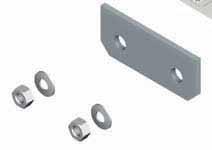
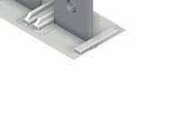
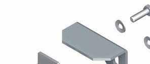
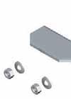
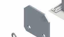
124 SIRCO PV IEC Load break switches for photovoltaic applications Bridging bars for connecting poles in series (continued) acces_374_a_1_x_cat Fig. 1 acces_376_a_1_x_cat Fig. 3 acces_386_a_1_x_cat acces_378_a_1_x_cat acces_374_a_1_x_cat Fig. 2 Fig.4 Fig. 5 General Catalogue
125 SIRCO PV IEC Load break switches for photovoltaic applications Characteristics Characteristics according to IEC Rated current In 100 A 160 A Thermal current at 40 C (A) Thermal current at 50 C (A) Thermal current at 60 C (A) Rated insulation voltage U i (V) Rated impulse withstand voltage U imp (kv) Number of pole(s) in series per circuit Number of pole(s) of the device Frame size I e (A) Number of pole(s) in series per circuit Number of pole(s) of the device Number of circuits Rated voltage Utilisation category I e (A) Frame size 1 circuit 1000 VDC DC21 B P ; 1 P 2 P B P ; 1 P 2 P B4 1 circuit 1500 VDC DC21 B P ; 1 P 4 P B4 DS P ; 1 P 4 P B4 DS 2 circuits 1000 VDC DC21 B P ; 1 P 4 P B4 DS P ; 1 P 4 P B4 DS Rated shorttime withstand current 0.3 s. (ka eff) Rated shorttime withstand current 1 s. (ka eff) 5 5 Connection Maximum Cu rigid cable crosssection (mm²) Maximum Cu busbar width (mm) Tightening torque min (Nm) Tightening torque max (Nm) Mechanical characteristics Durability (number of operating cycles) Operating effort (Nm) Weight of a 2 pole device (kg) Weight of a 4 pole device (kg) Rated current In 250 A 275 A Thermal current at 40 C (A) Thermal current at 50 C (A) Thermal current at 60 C (A) Rated insulation voltage U i (V) Rated impulse withstand voltage U imp (kv) Number of pole(s) in series per circuit Number of pole(s) of the device Frame size I e (A) Number of pole(s) in series per circuit Number of pole(s) of the device Number of circuits Rated voltage Utilisation category I e (A) Frame size 1 circuit 1000 VDC DC21 B P ; 1 P 2 P B P ; 1 P 3 P B5 1 circuit 1500 VDC DC21 B P ; 1 P 4 P B4 DS P ; 1 P 3 P B5 2 circuits 1000 VDC DC21 B P ; 1 P 4 P B4 DS P ; 1 P 6 P B5 DS 2 circuits 1500 VDC DC21 B P ; 1 P 6 P B5 DS 4 circuits 1000 VDC DC21 B P ; 1 P 8 P B5 DS Rated shorttime withstand current 0.3 s. (ka eff) Rated shorttime withstand current 1 s. (ka eff) 5 5 Connection Maximum Cu rigid cable crosssection (mm²) Maximum Cu busbar width (mm) Tightening torque min (Nm) Tightening torque max (Nm) Mechanical characteristics Durability (number of operating cycles) Operating effort (Nm) Weight of a 2 pole device (kg) 1.8 Weight of a 3 pole device (kg) 6 Weight of a 4 pole device (kg) 4.3 Weight of a 6 pole device (kg) 12.3 Weight of an 8 pole device (kg) General Catalogue
126 SIRCO PV IEC Load break switches for photovoltaic applications Characteristics according to IEC (continued) Rated current In 315 A 400 A Thermal current at 40 C (A) Thermal current at 50 C (A) Thermal current at 60 C (A) Rated insulation voltage U i (V) Rated impulse withstand voltage U imp (kv) Number of circuits Rated voltage (1) For a rated operational voltage Ue = 400 VAC. (1) For a rated operational voltage Ue = 400 VAC. Utilisation category I e (A) Number of pole(s) in series per circuit Number of pole(s) of the device Frame size I e (A) Number of pole(s) in series per circuit Number of pole(s) of the device 1 circuit 1000 VDC DC21 B P ; 1 P 2 P B P ; 2 P 4 P B4 1 circuit 1500 VDC DC21 B P ; 1 P 3 P B P ; 1 P 3 P B5 2 circuits 1000 VDC DC21 B P ; 1 P 4 P B4 DS P ; 1 P 4 P B5 2 circuits 1500 VDC DC21 B P ; 1 P 6 P B5 DS 4 circuits 1000 VDC DC21 B P ; 1 P 8 P B5 DS Rated shorttime withstand current 0.3 s. (ka eff) 10 Rated shorttime withstand current 1 s. (ka eff) 5 10 Rated peak withstand current (ka peak) (1) Connection Maximum Cu rigid cable crosssection (mm²) Maximum Cu busbar width (mm) Tightening torque min (Nm) Tightening torque max (Nm) Mechanical characteristics Durability (number of operating cycles) Operating effort (Nm) Weight of a 2 pole device (kg) 1.8 Weight of a 3 pole device (kg) 6 6 (B4) / 3.8 (B5) Weight of a 4 pole device (kg) Weight of a 6 pole device (kg) 12.3 Weight of an 8 pole device (kg) 15 Rated current In 500 A 630 A Thermal current at 40 C (A) Thermal current at 40 C (A) Thermal current at 60 C (A) B4: 475 / B5: Rated insulation voltage U i (V) Rated impulse withstand voltage U imp (kv) Number of pole(s) in series per circuit Number of pole(s) of the device Number of pole(s) in series per circuit Number of pole(s) of the device Number of circuits Rated voltage Utilisation category I e (A) Frame size I e (A) Frame size 1 circuit 1000 VDC DC21 B P ; 2 P 4 P B P ; 2 P 4 P B5 1 circuit 1500 VDC DC21 B P ; 1 P 3 P B P ; 4 P 8 P B5 DS 2 circuits 1000 VDC DC21 B P ; 1 P 4 P B P ; 2 P 8 P B5 DS 2 circuits 1500 VDC DC21 B P ; 1 P 6 P B5 DS 4 circuits 1000 VDC DC21 B P ; 1 P 8 P B5 DS Rated shorttime withstand current 1 s. (ka eff) Connection Maximum Cu rigid cable crosssection (mm²) 2x150 2x185 Maximum Cu busbar width (mm) Tightening torque min (Nm) Tightening torque max (Nm) Mechanical characteristics Durability (number of operating cycles) Operating effort (Nm) Weight of a 3 pole device (kg) 6 (B4) / 3.8 (B5) Weight of a 4 pole device (kg) Weight of a 6 pole device (kg) 12.3 Weight of an 8 pole device (kg) Frame size General Catalogue
127 SIRCO PV IEC Load break switches for photovoltaic applications Characteristics (continued) Characteristics according to IEC (continued) Rated current In 800 A 1250 A Thermal current at 40 C (A) Thermal current at 50 C (A) Thermal current at 60 C (A) B5: 650 / B6: Rated insulation voltage U i (V) Rated impulse withstand voltage U imp (kv) Number of pole(s) in series per circuit Number of pole(s) of the device Number of pole(s) in series per circuit Number of pole(s) of the device Number of circuits Rated voltage Utilisation category I e (A) Frame size I e (A) Frame size 1 circuit 1000 VDC DC21 B P ; 2 P 4 P B A 2 P ; 2 P 4 P B6 1 circuit 1500 VDC DC21 B P ; 4 P 8 P B6 DS 1250 A 4 P ; 4 P 8 P B6 DS 2 circuits 1000 VDC DC21 B P ; 2 P 8 P B6 DS 1250 A 2 P ; 2 P 8 P B6 DS Rated shorttime withstand current 1 s. (ka eff) Connection Maximum Cu rigid cable crosssection (mm²) 2x240 2x240 Maximum Cu busbar width (mm) Tightening torque min (Nm) Tightening torque max (Nm) Mechanical characteristics Durability (number of operating cycles) Operating effort (Nm) Weight of a 4 pole device (kg) Weight of an 8 pole device (kg) Rated current In 2000 A 3200 A Thermal current at 40 C (A) Thermal current at 50 C (A) Thermal current at 60 C (A) Rated insulation voltage U i (V) 1500 Rated impulse withstand voltage U imp (kv) 12 Number of pole(s) in series per circuit Number of pole(s) of the device Number of pole(s) in series per circuit Number of pole(s) of the device Number of circuits Rated voltage Utilisation category I e (A) Frame size I e (A) Frame size 1 circuit 1000 VDC DC21 B 2000 A 2 P ; 2 P 4 P B A 2 P ; 2 P 4 P B8 1 circuit 1500 VDC DC21 B 2000 A 4 P ; 4 P 8 P B7 DS 2 circuits 1000 VDC DC21 B 2000 A 2 P ; 2 P 8 P B7 DS Rated shorttime withstand current 1 s. (ka eff) Connection Maximum Cu busbar width (mm) x 100 x 5 Tightening torque min (Nm) Tightening torque max (Nm) Mechanical characteristics Durability (number of operating cycles) Operating effort (Nm) Weight of a 4 pole device (kg) Weight of an 8 pole device (kg) General Catalogue
128 SIRCO PV IEC Load break switches for photovoltaic applications Pole connections in series 1 PV circuit 1000 VDC 1 PV circuit 1500 VDC B4 2P B4B8 4P B5 3P B5 DS B7 DS 8P () () () B A () () sirco_075_a_1_x_cat () 1 () sirco_076_a_1_x_cat () () 1 () () sirco_077_a_1_x_cat () () 1 () sirco_077_a_1_x_cat () () 1 2 PV circuits 1000 VDC B4 DS 4P B5 4P B5 DS B7 DS 8P () () 1 2 () () B () () () () B A () () A () () () () sirco_082_a_1_x_cat sirco_079_a_1_x_cat () 2 PV circuits 1500 VDC () () 1 1 () B5 DS 6P () A () () 2 () 2 () B () sirco_080_a_1_x_cat () () () 1 2 () sirco_083_a_1_x_cat sirco_081_a_1_x_cat 4 PV circuits 1000 VDC B5 DS 8P () () () () () () () () 1 2 A () () () () () () () () 3 4 () B 1 () () () 2 A. Front switch. B. Rear switch. 1. Utility 1 2. Utility 2 3. Utility 3 4. Utility 4 General Catalogue
129 SIRCO PV IEC Load break switches for photovoltaic applications Dimensions (mm) B4 B5 J 1 Ø 9 B4 J1 7.5 Ø 7 Y Ø 11 K2 K K1 B H 30 B5 45 H 20 Ø 13 sirco_068_a_1_x_cat J2 J3 A C and 500 A excepted. Frame size No. of poles A B C H J J1 J2 J3 K K1 K2 Y B4 2 P B4 4 P B5 2 P B5 3 P B5 4 P B4 DS B5 DS Ø Ø 7 C B4 DS 25 J1 J Y Y Ø K1 B5 DS B Ø H K H sirco_069_a_1_x_cat A J3 J2 H1 Frame size No. of poles A B C H H1 J J1 J2 J3 K K1 Y Y1 B4 DS 4 P B5 DS 6 P B5 DS 8 P General Catalogue
130 SIRCO PV IEC Load break switches for photovoltaic applications B6 J C J1 Y H H K2 K K 65 B 4 x Ø16 Ø 9 sirco_070_a_1_x_cat 80 A H1 Frame size No. of poles A B C H H1 J J1 K K1 K2 Y B6 4 P B6 DS J J1 Y1 C Y 11 B K K H H 65 4 x Ø16 sirco_071_a_1_x_cat A 80 H1 Frame size No. of poles A B C H H1 J J1 K K1 Y Y1 B6 ds 8 P General Catalogue
131 SIRCO PV IEC Load break switches for photovoltaic applications Dimensions (mm) (continued) B7 J1 J Y C Ø12.5 B7 DS J1 J Y C Y1 B K K1 9 H H K2 K1 sirco_073_a_1_x_cat K B H H 120 H1 A Frame size No. of poles A B C H H1 H2 J J1 K K1 K2 Y B7 4 P Ø12.5 sirco_074_a_1_x_cat 120 A H1 Frame size No. of poles A B C H H1 J J1 K K1 Y Y1 B7 DS 8 P Dimensions of SIRCO PV 3200A 1000 VDC B8, please consult us. 146 General Catalogue
132 SIRCO PV IEC Load break switches for photovoltaic applications Dimensions for external handles (mm) B4 B4 DS B5 Handle type S2 type Front operation Direction of operation 0 Door drilling 40 Ø Ø 7 poign_013_a_1_gb_cat I Ø B5 DS B6 B7 Handle type S4 type Front operation Direction of operation Door drilling I Ø78 90 Ø 37 poign_036_a_1_gb_cat Ø B8 B6 DS B7 DS Handle type V1 type Front operation Direction of operation I Door drilling 50 4 Ø 6.5 poign_037_a_1_gb_cat Ø General Catalogue
133 SIRCO PV IEC Load break switches for photovoltaic applications Bridging bars (mm) B B5 B5 DS sircoul_030_a_1_x_cat Ø11 sircoul_062_b_1_x_cat Ø B sircoul_031_a_1_x_cat Ø sircoul_062_a_1_x_cat Ø B B sircoul_032_a_1_x_cat Ø 9 5 sircoul_034_a_1_x_cat Ø General Catalogue
134 SIRCO PV IEC Load break switches for photovoltaic applications Mounting orientation All frames B4 DS B5 DS B6 DS B7 DS sircoul_028_a_1_x_cat sirco_271_a_1_x_cat sirco_271_a_1_x_cat General Catalogue

135 INOSYS LBS Load Break Switches for DC & PV applications from 160 to 1250 A, up to 1500 VDC incorporating tripping function Load break switches new The solution for > Disconnection within PV installation > Battery protection > Rapid shutdown for firefighter safety > Isolation of DC processes Function INOSYS LBS are multipolar load break switches which are available with integrated tripping function. They can be operated manually using the handle or remotely (via tripping coils) to disconnect part or all of the electrical installation. They make and break under load conditions, provide safety isolation for any low voltage circuits up to 1500 VDC and are suitable for emergency switching. Advantages INOSYS LBS 2poles Highperformance switching in a compact frame INOSYS LBS switches integrate a patented technology that offers high switching capacity of 500 VDC per pole with optimum arc containment and significant power loss reduction all within a compact device. Safe & reliable operation Reliable position indication through visible contacts. ON, OFF and TRIP positions are stable: resistant to voltage fluctuations. The trip position provides complete disconnection and isolation. The opening and closing of the switch is fully independent from the speed of operation, ensuring safe operation under all conditions. High temperature withstand: no derating up to 55 C (131 F). Modular solution for a flexible configuration Multicircuit Disconnect up to three circuits with one switch: a compact and cost effective solution for recombiner and inverter applications. inosy_056_a.psd INOSYS LBS 3poles with tripping function Tripping function: flexible and robust Fully immune to external perturbation: no nuisance tripping. Shunttrip or undervoltage release from Wide operating temperature range: 25 to 70 C (15 to 160 F). Fast disconnection (<50 ms) for rapid firefighter shutdown, compliant with installation standards. Compatible with virtually any ArcFault Detection System, including the Easy to install Mechanism can be centred or left aligned (in the factory) to accommodate installation requirements. Wiring: as the switch is nonpolarised all types of wiring and connections are possible. Easy access without tools to integrate auxiliary contacts and tripping coil (both located within the switch footprint). inosy_002_a.eps Strong points > Highperformance switching in a compact frame > Safe & reliable operation > Tripping function > Easy to install > Modular solution Conformity to standards > IEC > UL 98B Compatible with requirements: > IEC > NEC art. 690 Single or dual polarity switching The same switch can be used for installation with either grounded or floating networks by choosing the wiring configuration. sircomc_024_a sircomc_084_a Single polarity switching sircomc_026_a Dual polarity switching 150 General Catalogue
136 INOSYS LBS Load Break Switches for DC & PV applications from 160 to 1250 A, up to 1500 VDC incorporating tripping function Typical applications: local and remote safe disconnection for DC and PV applications PV installation: Combiner box, Recombiner box or Inverter Battery protection INOSYS LBS INOSYS LBS inosy_013_b_1_x_cat Rapid shutdown for firefighter safety (compliant with installation standards, incl. NEC 2014) Isolation of DC processes PV panels inosy_005_a_1_gb_cat inosy_014_b_1_x_cat inosy_118_a PV inverter Switchboard cabinet INOSYS LBS INOSYS LBS The SOCOMEC solutions SIRCO PV Manual operation PV switches INOSYS LBS Up to 1500 VDC with visible contact indication with or without tripping function sircopv_ _a up to 3200 A at 1000 VDC up to 2000 A at 1500 VDC up to 4 circuits inosy_ _a up to 1250 A at 1000 VDC up to 800 A at 1500 VDC up to 2 circuits General Catalogue

 Frame size 160 A F2 250 A F2 315 A F2 400 A F3 630 A F3 No.")
137 INOSYS LBS Load Break Switches for DC & PV applications from 160 to 1250 A, up to 1500 VDC incorporating tripping function Overview inosy_057_a_1_x_cat.ai INOSYS LBS 400 A 1000 VDC with tripping function 2. INOSYS LBS 400 A 1000 VDC without tripping function 3. Door interlocked external operation handle 4. Direct operation handle 5. Shaft for external handle 6. Auxiliary contact 7. Tripping coil 8. Interphase barrier 9. Terminal shrouds 10. Terminal screens 11. Bridging bars for connecting poles in series 12. Captive nut 13. Holding insert 14. Terminal lugs References 1000 VDC 1 circuit Rating (A) Frame size 160 A F2 250 A F2 315 A F2 400 A F3 630 A F3 No. of poles per circuit 2 P (1 P, 1 P) 2 P (1 P, 1 P) 2 P (1 P, 1 P) 2 P (1 P, 1 P) 2 P (1 P, 1 P) Switch with tripping function Switch without tripping function Other compatible accessories External External Switch body (3) operation Tripping coil Switch body (3) operation Aux. Contact Bridging Bar (2) Shaft Shaft 84P mm 86P mm Shunt trip coil 84P S2 type handle S2 type handle 24 V AC/DC 86P Black IP Black IP V AC/DC P Black IP65 742F P V AC/DC P P Undervoltage releases Shaft 84P mm 48 VAC 86P Black IP Shaft 320mm NO/NC A F A 2 x F A 2 x F3 2 P (1 P, 1 P) 4 P (1) (2 P //, 2 P //) 4 P (1) (2 P //, 2 P //) S2L type handle 230 VAC 84P P Black IP55 84P A Black IP65 74AF VDC VDC P P P S2L type handle Black IP55 14A Black IP65 14A (1) Bridging bars for poles in parallel included with the switch body. (2) For isolated networks. (3) The switches are supplied without accessories. 152 General Catalogue
138 INOSYS LBS Load Break Switches for DC & PV applications from 160 to 1250 A, up to 1500 VDC incorporating tripping function References (continued) 1000 VDC 2 circuits Rating (A) Frame size No. of poles per circuit (1) Switch body (3) Switch with tripping function Switch without tripping function Other compatible accessories External External operation Tripping coil Switch body (3) operation Aux. Contact Bridging Bar (2) 160 A F2 250 A F2 315 A F2 400 A F3 630 A F3 2 P (1 P, 1 P) 2 P (1 P, 1 P) 2 P (1 P, 1 P) 2 P (1 P, 1 P) 2 P (1 P, 1 P) 84P Shaft 320mm Shunt trip coil 24 V AC/DC S2 type handle 84P V AC/DC 86P Black IP V AC/DC Black IP P F P P Shaft 320mm S2L type handle Undervoltage releases 48 VAC VAC P P P P VDC Black IP55 74A Shaft 320mm S2 type handle Black IP Black IP Shaft 320mm S2L type handle Black IP55 14A NO/NC A F3 2 P (1 P, 1 P) 48 VDC Black IP65 84P AF P Black IP65 14A (1) 4pole product with 2 poles per circuit 1 P, 1 P. (2) For isolated networks. (3) The switches are supplied without accessories VDC 1 circuit Rating (A) Frame size No. of poles per circuit Switch body (2) Switch with tripping function Switch without tripping function Other compatible accessories External External operation Tripping coil Switch body (2) operation Aux. Contact Bridging Bar (1) 160 A F2 250 A F2 315 A F2 400 A F3 630 A F3 800 A F3 3 P (2 P, 1 P) 3 P (2 P, 1 P) 3 P (2 P, 1 P) 3 P (2 P, 1 P) 3 P (2 P, 1 P) 3 P (2 P, 1 P) 84P Shaft 320mm Shunt trip coil 24 V AC/DC S2 type handle 84P V AC/DC 86P Black IP V AC/DC Black IP P F P P Shaft 320mm S2L type handle Undervoltage releases 48 VAC VAC P P P P VDC Black IP55 74A Shaft 320mm S2 type handle Black IP Black IP Shaft 320mm S2L type handle Black IP55 14A NO/NC VDC Black IP65 Black IP65 84P AF P A (1) For isolated networks. (2) The switches are supplied without accessories. General Catalogue
139 INOSYS LBS Load Break Switches for DC & PV applications from 160 to 1250 A, up to 1500 VDC incorporating tripping function Accessories Direct operation handle Frame size Handle type Handle colour Reference F2 E2 Black F2 E2 Red F3 E3 Black E2 type handle acces_400_a_1_cat Door interlocked external operation handle Door interlocked external operation handles include an escutcheon and are padlockable. External handles must be utilised with an extension shaft. Example of application As the handle is interlocked in the ON position the operator must safely disconnect and isolate the circuit prior to accessing the panel for maintenance procedures. Opening the door when the switch is in the ON position can only be done by defeating the interlocking function with the use of a dedicated tool (authorised persons only). The interlocking function is restored when the door is reclosed. S2 type handle acces_150_a_1_cat.eps For LBS with tripping function Frame size Handle type Handle colour Degree of protection Reference F2 S2 Black IP F2 S2 Black IP65 742F 2118 F2 S2 Red IP65 742G 2118 F3 S2L (1) Black IP55 74A F3 S2L (1) Black IP65 74AF 2118 F3 S2L (1) Red IP65 74AG 2118 (1) S2L handles have an extended grip; please refer to the dimensions section. For LBS without tripping function Frame size Handle type Handle colour Degree of protection Reference F2 S2 Black IP F2 S2 Black IP F2 S2 Red IP F3 S2L (1) Black IP55 14A F3 S2L (1) Black IP65 14A F3 S2L (1) Red IP65 14A (1) S2L handles have an extended grip; please refer to the dimensions section. Shaft for external handle Frame size Handle type Length (mm) Reference F2 F3 S2, S2L F2 F3 S2, S2L F2 F3 S2, S2L Other lengths: please consult us. Shaft for S2 and S2L type handle acces_401_a_1_cat Shaft guide for external handle To guide the shaft extension into the external handle. This accessory enables the handle to engage the extension shaft with a misalignment of up to 15 mm / 0.59 in. Required for a shaft length over 320 mm / 12.6 in. Description Reference Shaft guide acces_260_a_2_cat 154 General Catalogue
140 INOSYS LBS Load Break Switches for DC & PV applications from 160 to 1250 A, up to 1500 VDC incorporating tripping function Alternative Stype handle cover colours For S2 and S2L type single grip handles. Handle colour Handle type To be ordered in multiples of Reference Light grey S2, S2L Dark grey S2, S2L Other colours: please consult us. acces_198_a_1_cat Auxiliary contact The same auxiliary contact can be used to provide position and tripping information. The function of the auxiliary contact depends on where it is mounted on the mechanism. Characteristics Changeover type: NO/NC, IP2 with front operation operations. Maximum 3 per switch. Frame size Connection type Type Reference F2 F3 Screw NO/NC standard F2 F3 Screw NO/NC low level F2 F3 Screw NC > 600 V acces_402_a_1_cat Characteristics 24 VDC Operating current I e (A) 48 VDC 230 VAC 440 VAC 690 VAC Auxiliary contact type Min. current (A) I th (A) DC14 DC14 AC15 AC15 AC15 Standard 12.5 ma / 24 V Low level 1 ma / 4 V > 600 V 10 ma / 24 V acces_403_a_1_gb_cat Position (prebreak) Trip Position PRE TRIP POS Switch with tripping function Position Position (prebreak) POS PRE PRE acces_403_a_1_gb_cat Switch without tripping function Bridging bar for poles in series The bridging bars enable the poles to be connected in series, allowing the following configurations for 1500 VDC. Connection diagrams, see Pole connection in series page 162. Frame size Rating (A) Quantity to be ordered for 1500 VDC configuration Reference F (1) (2) F (1) (2) F (1) (1) For insulated network (switching of both polarities and ). (2) Kit comprises 2 identical bridging bars. acce_410_a_1_cat acce_411_a_1_cat General Catalogue
141 INOSYS LBS Load Break Switches for DC & PV applications from 160 to 1250 A, up to 1500 VDC incorporating tripping function Accessories (continued) Tripping coil Allows remote activation of the switch s tripping mechanism. Shunt trip and undervoltage release coils are available. Maximum one tripping coil per switch. Safe and easy coil replacement by using standard tools. Shunt trip coil Frame size Voltage (V) Reference F2 F3 24 V AC/DC F2 F3 48 V AC/DC F2 F VAC ; VDC F2 F3 230 V AC/DC Other voltage ratings available, please consult us. Undervoltage release Frame size Voltage (V) Reference F2 F3 48 VAC F2 F VAC F2 F VAC F2 F3 24 VDC F2 F3 48 VDC Other voltage ratings available, please consult us. Shunt trip coil acces_404_a_1_cat Characteristics Shunt trip coils AC type (±10%) 24 VAC 48 VAC 110 VAC 230 VAC Inrush consumption (A); <10ms DC type (5% 20%) 24 VDC 48 VDC 110 VDC 230 VDC Inrush consumption (A), <10ms Max supply time 2 s. Undervoltage release AC type 24 VAC 48 VAC 110 VAC 230 VAC Max permanent consumption (VA), at 110% U n DC type 24 VDC 48 VDC 110 VDC 230 VDC Max permanent consumption (VA), at 110% U n Holding: up to 85% x Un Release: < 35 to 70% x Un Interphase barrier Provides safety isolation between the terminals, essential for use at 1000 and 1500 VDC or between 2 circuits. Frame size Type Pack (unit) Reference F2 F3 Short F2 F3 Short F2 F3 Long F2 F3 Long acces_406_a_1_cat acces_405_a_1_cat 156 General Catalogue
142 INOSYS LBS Load Break Switches for DC & PV applications from 160 to 1250 A, up to 1500 VDC incorporating tripping function Terminal shroud For top or bottom protection against direct contact with terminals or connection parts; provides IP4 protection and phase separation. 1 P type to cover 1 pole bar. Advantages Perforations for thermographic inspection / voltage check without the need to remove the shrouds. Terminal shrouds can be fixed in place with a holding insert. Includes breakoff tabs for precise adaptation to cables or insulated bars. Frame size Pack (unit) No. of poles Position Reference F2 3 1 P Top or bottom (1) F2 4 1 P Top or bottom (1) F2 1 2 P Top or bottom (1) F3 3 1 P Top or bottom (1) F3 4 1 P Top or bottom (1) F3 1 2 P Top or bottom (1) Compatible with the holding insert which can be fitted to lock the shrouds in place. acces_407_a_1_cat Terminal screen Provides top and bottom protection against direct contact with terminals or connection parts. Advantages Perforations for thermographic inspection. Mounting requires holding inserts (supplied with the terminal screens). Frame size No. of poles Position Reference (1) F2 2 P Top and bottom F2 3 P Top and bottom F2 4 P Top and bottom F3 2 P Top and bottom F3 3 P Top and bottom F3 4 P Top and bottom (1) Each reference comprises 2 terminal screens for top and bottom protection. acces_408_a_1_cat Holding insert d to secure terminal shrouds / interphase barriers on the switch. Frame size Pack (unit) Reference F2 F F2 F acces_409_a_1_cat General Catalogue
143 INOSYS LBS Load Break Switches for DC & PV applications from 160 to 1250 A, up to 1500 VDC incorporating tripping function Accessories (continued) Captive nut This accessory enables simple onesided connection to the power terminals. It can be mounted on either side of the terminal for front or rear connection. Frame size Pack (unit) Reference F F F F acce_399_a_1_cat Voltage tap Allows connection of voltage sensing or power cables, with faston connection. Frame size Pack (unit) Reference F F acce_412_a_1_cat Characteristics Characteristics according to IEC Rated current I n 160 A 250 A 315 A 400 A 630 A 800 A 1000 A 1250 A Frame size F2 F2 F2 F3 F3 F3 2 x F3 2 x F3 Thermal current at 40 C (A) Thermal current at 50 C (A) Thermal current at 60 C (A) Rated insulation voltage U i (V) Rated impulse withstand voltage U imp (kv) Number of circuits Rated voltage Utilisation category I e (A) I e (A) I e (A) I e (A) I e (A) I e (A) I e (A) I e (A) 1 circuit 1000 VDC (1) DC21 B circuit 1000 VDC (1) DC22 B circuit 1000 VDC (1) PV circuit 1500 VDC (2) DC21 B circuit 1500 VDC (2) DC22 B circuit 1500 VDC (2) PV circuits 1000 VDC (1) DC21 B circuits 1000 VDC (1) DC22 B circuits 1000 VDC (1) PV Shortcircuit capacity at 1000 & 1500 VDC (without protection) Rated shorttime withstand current I cw 1s (ka eff.) Rated shortcircuit making capacity I cm (ka peak) 60 ms Connection (4) x x x 300 (3) 2 x 400 (3) Recommended Cu busbar width (mm) (4) Mechanical characteristics Durability (number of operating cycles) (1) 2 poles in series. (2) 3 poles in series. (3) Cu busbar. (4) For aluminium connection, please consult us. 158 General Catalogue
144 INOSYS LBS Load Break Switches for DC & PV applications from 160 to 1250 A, up to 1500 VDC incorporating tripping function Dimensions (in/mm) INOSYS LBS with tripping function J J2 J J3 J1 J4 J J2 B 1.77 / 45 = = B / 250 = = J5 J6 P2 B3 = = = = J6 J6 P2 B2 B1 = = J P / 50 A A A / / Interphase barrier. C 2. Terminal screens / 5.4 Connection terminal F2 Connection terminal F / 10 Parallel bridging F3 P P Terminal shrouds. 4. Double terminal shrouds. inosy_048_c_1_x_cat.ai inosy_060_a_1_x_cat.ai inosy_061_a_1_x_cat.ai 0.31 / / inosy_062_a_1_x_cat.ai A A1 J J1 No. of Rating (A) Frame size poles 2 P 3 P 4 P 22 P 2 P 3 P 4 P 2 P F F F3 in mm in mm in mm Rating (A) Frame size B B1 B2 B3 B4 C J2 J3 J4 J5 J6 J7 J8 P P1 P F F F3 in mm in mm in mm General Catalogue
145 INOSYS LBS Load Break Switches for DC & PV applications from 160 to 1250 A, up to 1500 VDC incorporating tripping function Dimensions (in/mm) INOSYS LBS without tripping function J B 1.77 / 45 = = B / 158 = = J5 J6 P2 B3 = = J2 J J3 J1 J4 J J2 J6 = = J6 P2 B2 B1 = = J7 1 2 P P1 P A A A / Interphase barrier / 126 C 2. Terminal screens / 5.4 Connection terminal F2 Connection terminal F / 10 Parallel bridging F inosy_060_a_1_x_cat.ai inosy_061_a_1_x_cat.ai 0.31 / / Terminal shrouds. 4. Double terminal shrouds inosy_062_a_1_x_cat.ai inosy_059_b_1_x_cat.ai A A1 J J1 Rating (A) Frame size No. of poles 2 P 3 P 4 P 22 P 2 P 3 P 4 P 2 P F2 in mm F3 in mm F3 in mm Rating (A) Frame size B B1 B2 B3 B4 C J2 J3 J4 J5 J6 J7 J8 P P1 P F2 in mm F3 in mm F3 in mm General Catalogue
146 INOSYS LBS Load Break Switches for DC & PV applications from 160 to 1250 A, up to 1500 VDC incorporating tripping function Dimensions for external handles (mm) F2 frame size Handle type Front operation Direction of operation Door drilling S2 type with trip 0 40 Ø 78 Reset Trip 4 Ø I Ø poign_057_a_1_gb_cat.eps Handle type S2 type Front operation Direction of operation 0 Door drilling 40 Ø Ø I Ø poign_013_a_1_gb_cat.eps F3 frame size Handle type Front operation Direction of operation Door drilling S2L type with trip 0 40 Ø 78 Reset Trip 4 Ø 7 I Ø 37 poign_068_a_1_gb_cat.eps Handle type S2L type Front operation Direction of operation 0 Door drilling 40 Ø Ø 7 I Ø 37 poign_069_a_1_gb_cat.eps General Catalogue
147 INOSYS LBS Load Break Switches for DC & PV applications from 160 to 1250 A, up to 1500 VDC incorporating tripping function Pole connections in series 1 PV circuit 1000 VDC 2 PV circuits 1000 VDC 1 PV circuit 1500 VDC F2F3 2 P 2x F3 4P F2F3 2 x 2 P F2F3 3 P () () () 1 () () 1 2 () () () () () 1 () sircopv_075_a_1_x_cat.eps () () sircopv_118_a_1_x_cat.eps () () () 1 2 () sircopv_080_a_1_x_cat.eps () () 1 () sircopv_077_a_1_x_cat.eps 1. Circuit 1 2. Circuit 2 Bridging bars (mm/in) F (1) (1) Kit comprises 2 identical bars. F (1) (1) Kit comprises 2 identical bars M inosy_043_a_1_x_cat.ai M inosy_044_a_1_x_cat.ai F M10 M inosy_055_a_1_x_cat.ai inosy_016_a_1_x_cat.ai 162 General Catalogue


148 INOSYS LBS Load Break Switches for DC & PV applications from 160 to 1250 A, up to 1500 VDC incorporating tripping function Mounting orientation F2 F3 All mounting orientations are possible. Derating may apply please consult us. inosy_006_a.psd General Catalogue


. 2 stable positions (I, 0).")
149 SIRCO MOT PV Load break switches for photovoltaic applications remotely operated range from 250 to 3200 A, up to 1000 VDC The solution for Load break switches sircopv_016_b_1_cat > Buildings > Solar parks > Solar inverters SIRCO MOT PV 4 x 400 A Strong points sircopv_107_a_1_cat > High breaking capacity up to 3200 A, 1000 VDC > Remotely operated product > Manual emergency operation Function SIRCO MOT PV 4 x 2000 A Conformity to standards > IEC SIRCO PV are remotely operated multipolar load break switches. They make and break under load conditions and provide safety isolation for any low voltage circuit dedicated to photovoltaic applications up to 1000 VDC. Advantages High breaking performance A glass fibre reinforced polyester break chamber with an arc extinguishing system provides a patented safety disconnection system offering rapid extinguishing of the electric arc up to 1000 VDC and current interruption up to 3200 A. General characteristics Up to 1000 VDC from 250 to 3200 A. Remotely operated product (motor control). 2 stable positions (I, 0). Remotely operated product photovoltaic installations and solar inverters. They can be remotely controlled via voltfree contacts, from either an external automatic controller or a switch. Manual emergency operation In addition to its motorised operation, the operation facility, enabling the switch position to be changed directly on the device if required. 164 General Catalogue

150 SIRCO MOT PV Load break switches for photovoltaic applications remotely operated range from 250 to 3200 A, up to 1000 VDC References 1000 VDC Back plate mounting Rating (A) / Frame size Circuit type No. of poles Switch body 250 A / B4 19PV A / B4 19PV A / B5 19PV A / B5 19PV 4080 Bridging bars for connecting poles in series Inter phase barrier Terminal screens Terminal shrouds (1) (1) (2) (3) (3) 1000 A / B6 19PV A / B6 19PV (1) A / B7 19PV A / B7 19PV A / B8 19PV 4320 included (1) (1) (1) Connection in series of 2 or 4 poles of the device (2) 2 pieces: one for top side and another for bottom side. (3) Terminal shrouds cannot be mounted when bridging bars for connecting poles in series are present. Accessories Bridging bars for connecting poles in series The bridging bars will make easy the connection of poles in series, allowing the following configurations: Bottom/Bottom Top/Top Top/Bottom Bottom/Top Connection diagrams: page 171. Frame size Rating (A) Number of poles of the device in series Pack Reference B piece B pieces B pieces B pieces B pieces B pieces B pieces B7 B piece Auxiliary contact 1 to 2 NO/NC auxiliary contacts (1 as standard). Low level auxiliary contacts: please consult us. Connection to the control circuit By 6.35 mm faston terminal. Electrical characteristics operations. Characteristics Operating current I e (A) Rating (A) Nominal current (A) 250 VAC AC VAC AC13 24 VDC AC13 48 VDC AC Bridging bar 250 A Bridging bar A acces_065_a_1_cat acces_392_a_1_cat acces_334_a_1_cat References NO/NC changeover contact Frame size Rating (A) Contact(s) Reference B4 B nd B6 B nd B nd included svr_058_a_1_cat General Catalogue


 No.")
. Factory fitted.")
151 SIRCO MOT PV Load break switches for photovoltaic applications remotely operated range from 250 to 3200 A, up to 1000 VDC Accessories (continued) Terminal shrouds terminals or connecting parts. Not compatible for terminals with bridging bars connected. Advantage of terminal shrouds inspection without the need to remove the shrouds. Frame size Rating (A) No. of poles Position Reference B top or bottom B top or bottom acces_206_a_2_cat Terminal screens Top and bottom protection against direct contact with terminals or connection parts. Frame size Rating (A) No. of poles Position Reference B top or bottom B top or bottom B top or bottom B top or bottom B7 B top or bottom Inter phase barrier acces_207_a_2_cat phase barriers allow insulation between pole connected in series. Frame size Rating (A) No. of poles Pack Reference B pieces B pieces B6 B included acces_036_a_2_cat 2 position padlocking (I 0) Enables padlocking in position I (product can be padlocked in position 0 as standard). Factory fitted. Frame size Rating (A) Reference B4 B B6 B atys_854_a_1_cat Key handle interlocking system lock. Factory fitted. As standard, locking in position 0. Optional padlocking in 2 positions: Locking in position 0 and I. Frame size Rating (A) Reference B4 B B6 B atys_853_a_1_cat Other specific accessories Low level auxiliary contacts. 166 General Catalogue
152 SIRCO MOT PV Load break switches for photovoltaic applications remotely operated range from 250 to 3200 A, up to 1000 VDC two 230 VAC, 50/60 Hz networks. Input 200 VAC. Internal protection: each input is fuse protected 3.15 A. 2. Description of accessories Reference atys_616_a_1_cat and 2. Input 3. Output 2 atys_612_a_2_cat Increases the distance between the rear power terminals and the backplate by 10 mm. This accessory may also be used to replace the original mounting spacers. Frame size Rating (A) Description of accessories Reference B3 B set of 2 spacers atys_009_a_2_cat Door protective surround operation, display ) is required, the door surround can be utilised to provide a clean and safe finish to the panel's cutout. Frame size Rating (A) Reference B3 B B6 B atys_595_a_2_cat General Catalogue
153 SIRCO MOT PV Load break switches for photovoltaic applications remotely operated range from 250 to 3200 A, up to 1000 VDC Characteristics according to IEC to 3200 A Thermal current I th at 40 C 250 A 400 A 630 A 800 A 1000 A 1250 A 1600 A 2000 A 3200 A Rated insulation voltage U i (V) Rated impulse withstand voltage U imp (kv) Frame size B4 B4 B5 B5 B6 B6 B7 B7 B8 Rated operational currents I e (A) Rated voltage Utilisation category Number of poles of the device (1) Improved endurances: Please consult us. Number of pole(s) in series per polarity Ambient temperature ( C) (A) (A) (A) (A) (A) (A) (A) (A) (A) 1000 VDC DC21 B VDC DC21 B VDC DC21 B VDC DC21 B Switching time I Power supply 166/ / / / / / / / /332 Control supply power demand 276/ / / / / / / / /322 Connection Rigid Cu cable crosssection (mm 2 ) x x x x Tightening torque min/max (Nm) 20/26 40/45 40/45 40/45 40/45 40/45 40/45 40/45 40/45 Mechanical characteristics Durability (number of operating cycles) (1) Weight of a 4 pole device (kg) General Catalogue
154 SIRCO MOT PV Load break switches for photovoltaic applications remotely operated range from 250 to 3200 A, up to 1000 VDC Dimensions 250 to 800 A / B4 to B5 J M U W 3 sirco_311_d_1_x_cat AC AA BA CA CA Fix. 195 Fix. 180 = = Y V X T T T 11 F A Z H 4 C Fix. 195 Fix. 180 Ø7 W Ø CA U 1. Locking bracket 2. Maximum handle radius, operating angle 2 x Mounting spacers 4. Terminal shrouds 5. Dimension of the cutout 6. Handle Rating (A) / Overall dimensions Terminal shrouds Switch body Switch mounting Connection Frame size A 4p. C AC F 4p. H J M 4p. T U V W X 4p. Y Z AA BA CA 250 / B / B / B / B General Catalogue
155 SIRCO MOT PV Load break switches for photovoltaic applications remotely operated range from 250 to 3200 A, up to 1000 VDC Dimensions (continued) 1000 to 1250 A / B6 to B7 J M 51.5 U Rating (A) / Frame size 3200 A / B8 Overall dimensions Terminal shrouds Switch body Switch mounting Connection B AC F 4p. J 4p. M 4p. T U V X Y AA 1000 / B / B / B / B = AC B AA = V 12.5 X T T T 12.5 Y F ø sircopv_109_b_1_x_cat ø A sirco_270 1_x_cat A x Ø16 sircopv_110_c_1_x_cat 12.5 ø A ø sircopv_111_c_1_x_cat General Catalogue
156 SIRCO MOT PV Load break switches for photovoltaic applications remotely operated range from 250 to 3200 A, up to 1000 VDC Bridging bar A A sircoul_062_a_1_x_cat Ø11 sircoul_062_a_1_x_cat Ø A 1600 A 210 sircoul_062_a_1_x_cat Ø 9 sirco_033_a_1_x_cat 128,5 12,5 Ø 12,5 22, A 210 sircoul_062_a_1_x_cat Ø (1) 4 poles bottom / bottom sirco_307_b_1_gb_cat Load (1) Other connections: refer to mounting instructions General Catalogue


157 Load break switches for specific applications Load break switches Despite already offering a wide range of load break switches, SOCOMEC also manufactures specific products to suit any requirement. Some of these products can be seen on these two pages. This list is not exhaustive. Please do not hesitate to contact us. SIRCO range with overrated neutral Compliance with standards > IEC > BS EN > EN > NBN EN > VDE (1992) sirco_255_a_1_cat The use of power electronics is becoming more and more frequent. Chopper, rectifiers and current inverters distort the signal by reinjecting the 3rd order harmonics which are combined in the neutral. Range available from 125 to 1800 A. SIRCO 3 x 250 A with 400 A rated neutral SIRCO high shortcircuit withstand sirco_353_a_1_cat 80 ka rms 1 s. 110 ka rms 0.1 s. 240 ka peak. SIRCO early break AC sirco_380_a_1_cat Complete range from 125 to 3200 A. Double positive break indication given through a position indication window, located directly on the product, and by the operating handle. Features an early break auxiliary contact as standard. Severe load duty categories (AC22 and AC23). High resistance to damp heat (supplied "tropicalised"). SIRCO 3 x 1250 A with early prebreak AC 172 General Catalogue


158 Load break switches for specific applications INOSYS LBS inosy_002_a_ INOSYS LBS are load break switches integrating a patented breaking technology that allows a high breaking capacity up to 1000 VAC. Their modular design allows to configure the poles' availability ondemand and mix the ratings. SIRCO for earthing sirco_363_a_2_cat From 800 to 1800 A. 50 ka rms 1 s. Special S4 type handle. Undervoltage coil interlocking. sirco_338_a_1_x_cat General Catalogue

159 SIRCO MC PV UL 508I Load break switches for photovoltaic applications from 25 to 45 A, up to 1000 VDC The solution for Load break switches > Residential > Buildings > Solar parks sircomc_002_a_1_cat SIRCO MC PV 25 A 1000 VDC DINrail mounting Strong points > Compact > High breaking capacity up to 1000 VDC > Safety Conformity to standards > UL 508I Guide NMSJ, file E Function SIRCO MC PV are DC nonfusible disconnect switches. They make and break under load conditions and provide optimum safe isolation for any PV circuit. > IEC Advantages Compact Thanks to its compact design, the space needed within the combiner box or the solar inverter is greatly reduced. High breaking capacity up to 1000 VDC Making and breaking capacity under load conditions up to 1000 VDC. Specific photovoltaic test beyond standard. Safety Bridging bars are factory fitted for easier, quicker and safer connection. Direct access to connection terminals for adequate tightening. Approvals and certifications (1) (1) Product reference on request. sircomc_028_a SIRCO MC PV DINrail mounting 174 General Catalogue
160 SIRCO MC PV UL 508I Load break switches for photovoltaic applications from 25 to 45 A, up to 1000 VDC Multicircuit switching The SIRCO MC PV for dual circuits (2 MPPT: Maximum Power Point Tracking) enables connection of two independent photovoltaic circuits to a single switch in order to reduce the costs of the global solution. Inverter 1 Inverter 2 sircomc_045_a_1_gb_cat Completely isolate the inverter within one operation The SIRCO MC PV with two additional AC poles can be integrated into the inverter to provide complete and simultaneous isolation of the PV and AC circuits. This improves safety and reduces the overall product size. sircomc_020_a For grounded or ungrounded networks: It is possible to use the SIRCO MC PV in both network systems, either switching one or both polarities. sircomc_024_a_1_x_cat Panel Panel 2 Inverter sircomc_025_a_1_x_cat AC Panel AC What you need to know General Catalogue

161 SIRCO MC PV UL 508I Load break switches for photovoltaic applications from 25 to 45 A, up to 1000 VDC References Rating (A) Circuit type No. of poles Switch body Direct handle External handle Shaft for external handle Auxiliary contact Single PV circuit 2 P 21PV 2102UL 25 A 45 A Dual PV circuit 4 P 21PV 5102UL Single PV circuit 4 P 21PV 4144 Dual PV circuit 8 P 21PV 8144 MC01 type Blue MC01 type Blue S00 type Black 4.4X 147D 0111 (1) Red 4.4X 147R 0111 (1) S00 type contact NCNO (1) Door interlocking VDC Rating (A) Circuit type No. of poles Switch body Direct handle External handle Shaft for external handle Auxiliary contact Single PV circuit 4 P 21PV 4144 Dual PV circuit 8 P 21PV 8144 MC01 type Black MC01 type Black S00 type Black 4.4X 147D 0111 (1) Red 4.4X 147R 0111 (1) S00 type contact NCNO (1) Door interlocking. Accessories Direct operation handle Rating (A) Handle color Type of locking Handle type 45 mm modular DIN front plate Reference Blue MC0 yes (1) Blue MC01 yes (1) Standard handle. MC0 handle 2 MPPT 600 V Rating (A) Handle color Type of locking Handle type 45 mm modular DIN front plate Reference 25 Blue MC0 yes Blue MC01 yes Blue MC01 yes MC01 handle 176 General Catalogue

 Nema/UL protection degree. S00 handle Shaft for external handle MC1 handle The shaft can be adjusted and cut depending on the need.")
162 SIRCO MC PV UL 508I Load break switches for photovoltaic applications from 25 to 45 A, up to 1000 VDC External operation handle The external control will allow the operator to safely disconnect and isolate the solar strings prior to any intervention. External controls are userfriendly and adapted to meet requirements of residential installations, large roofs and groundbased generators. DINrail or back plate mounting Rating (A) Handle type Handle color Type of locking Protection degree (1) Reference MC1 Black 4.4X MC1 4.4X S00 Black 4.4X 147D S00 4.4X 147R 0111 (1) Nema/UL protection degree. S00 handle Shaft for external handle MC1 handle The shaft can be adjusted and cut depending on the need. Shaft length Device shaft: DINrail or back plate mounting Rating (A) Device shaft Length Reference (1) (1) Shaft for door interlocking. Terminal shrouds Top or bottom protection against direct contact with the terminals or connection parts. The SIRCO MC PV load break switch is prebridged. Terminal covers are mounted on the top or bottom free space of the device. Possibility to assemble a terminal shroud on the bridge side by removing the insulating material of the series connection bar (irreversible step). Rating (A) Type of mounting No. of poles Position Reference DINrail 1 P top or bottom DINrail top or bottom sircomc_011_e_1_cat Terminal shrouds 1 pole Terminal shrouds 3 pole General Catalogue
163 SIRCO MC PV UL 508I Load break switches for photovoltaic applications from 25 to 45 A, up to 1000 VDC Characteristics according to UL 508I General use rating with 200% overload extra test 25 A 45 A Rated voltage Number of poles of the device Number of PV circuits (A) (A) 2 P P x 2 P x 4 P VDC 4 P VDC 2 x 4 P 2 Shortcircuit capacity at 600 VDC Prospective shortcircuit current (ka rms) 5 5 Type of fuse gpv gpv Associated fuse rating (A) Shortcircuit capacity at 1000 VDC Prospective shortcircuit current (ka rms) 5 5 Connection terminals Mechanical characteristics Durability (number of operating cycles) Tightening torque (Nm) 2 2 Rated current 25 A 45 A Thermal current I th at 40 C (A) Thermal current at 50 C (A) Thermal current at 60 C (A) Rated insulation voltage U i (V) Rated impulse withstand voltage U imp (kv) 8 8 Rated operational currents I e (A) Rated voltage Number of poles of the device Number of PV circuits (A) (A) 2 P 1 4 P x 2 P 2 2 x 4 P VDC 2 P VDC 4 P VDC 2 x 2 P VDC 2 x 4 P General Catalogue
164 SIRCO MC PV UL 508I Load break switches for photovoltaic applications from 25 to 45 A, up to 1000 VDC DINrail mounting Direct operation A B 2.76 / / / sircomc_004_b_1_us_cat Ø 0.18 Ø Terminal shrouds 1P. 4. AC power pole. 5. AC or PV power pole. A. MC0 handle B. MC01 handle DINrail mounting External operation Min / Max Min / Max A Max Max / / / Max sircomc_005_b_1_xus_cat 1. Terminal shrouds 1P AC power pole AC or PV power pole. A. MC1 handle A 2.76 / / / ,80 71 Ø 0.18 Ø Auxiliary contact. A. MC01 handle. General Catalogue
165 SIRCO MC PV UL 508I Load break switches for photovoltaic applications from 25 to 45 A, up to 1000 VDC Dimensions (continued) DINrail mounting External operation Min / Max Min / Max A Max Max / / / sircomc_040_b_1_us_cat 2. Auxiliary contact. A. MC1 handle. DINrail or back plate mounting Handle type MC1 type Front operation Direction of operation I Door drilling poign_001_a_1_us_cat 0 OFF OFF Ø 0.55 Ø Ø 0,13 Ø Handle type Front operation Direction of operation Door drilling S00 type Ø 3.07 Ø I With 4 fixing screws Ø Ø 7 With fixing nut Ø 1.22 Ø Ø 0.89 Ø General Catalogue
166 SIRCO MC PV UL 508I Load break switches for photovoltaic applications from 25 to 45 A, up to 1000 VDC Poles connections Switching of polarities and (1) Single PV circuit Dual PV circuit sircomc_024_a_1_x_cat Rating Single PV circuit Dual PV circuit 21PV 2102UL 21PV 5102UL Inverter Inverter 1 Inverter sircomc_044_a_1_gb_cat 2 6 Panel 8 2 Panel Panel 2 sircomc_045_a_1_gb_cat 21PV PV 8144 Inverter Inverter 1 Inverter 1 Inverter Panel 8 Panel 8 Panel Panel Panel 2 8 Panel 2 (1) For grounded systems, single polarity switching, a bridge shall be added. For spare bridging bars, please consult use. General Catalogue
167 INOSYS LBS UL 98B Load Break Switches for DC & PV applications from 100 to 600 A, up to 1500 VDC incorporating tripping function Load break switches new The solution for > Disconnection within PV installation > Battery protection > Rapid shutdown for firefighter safety > Isolation of DC processes Strong points Function INOSYS LBS are multipolar load break switches which are available with integrated tripping function. They can be operated manually using the handle or remotely (via tripping coils) to disconnect part or all of the electrical installation. They make and break under load conditions, provide safety isolation for any low voltage circuits up to 1500 VDC and are suitable for emergency switching. Advantages INOSYS LBS 2poles Highperformance switching in a compact frame INOSYS LBS switches integrate a patented technology that offers high switching capacity of 500 VDC per pole with optimum arc containment and significant power loss reduction all within a compact device. Safe & reliable operation Reliable position indication through visible contacts. ON, OFF and TRIP positions are stable: resistant to voltage fluctuations. The trip position provides complete disconnection and isolation. The opening and closing of the switch is fully independent from the speed of operation, ensuring safe operation under all conditions. High temperature withstand: no derating up to 55 C (131 F). Modular solution for a flexible configuration Multicircuit Disconnect up to three circuits with one switch: a compact and cost effective solution for recombiner and inverter applications. inosy_082_a.psd INOSYS LBS 3poles with tripping function Tripping function: flexible and robust Fully immune to external disturbances: no nuisance tripping. Shunttrip or undervoltage release from Wide operating temperature range: 15 to 122 F (25 to 50 C). Fast disconnection (<50 ms) for rapid firefighter shutdown, compliant with installation standards. Compatible with virtually any ArcFault Detection System, including the Easy to install Mechanism can be centred or left aligned (in the factory) to accommodate installation requirements. Wiring: as the switch is nonpolarised all types of wiring and connections are possible. Easy access without tools to integrate auxiliary contacts and tripping coil (both located within the switch footprint). inosy_002_a.eps > Highperformance switching > Safe & reliable operation > Tripping function > Easy to install > Modular solution Conformity to standards > IEC > UL 98B Compatible with requirements: > IEC > NEC art. 690 Single or dual polarity switching The same switch can be used for installation with either grounded or floating networks by choosing the wiring configuration. sircomc_024_a sircomc_084_a Single polarity switching sircomc_026_a Dual polarity switching 182 General Catalogue

 Isolation of DC processes PV panels PV inverter Switchboard cabinet INOSYS LBS INOSYS LBS inosy_005_a_1_gb_cat inosy_014_b_1_x_cat inosy_118_a The SOCOMEC solutions SIRCO PV Manual")
168 INOSYS LBS UL 98B Load Break Switches for DC & PV applications from 100 to 600 A, up to 1500 VDC incorporating tripping function Typical applications: local and remote safe disconnection for DC and PV applications PV installation: Combiner box, Recombiner box or Inverter Battery protection INOSYS LBS INOSYS LBS inosy_013_b_1_x_cat Rapid shutdown for firefighter safety (compliant with installation standards, incl. NEC 2014) Isolation of DC processes PV panels PV inverter Switchboard cabinet INOSYS LBS INOSYS LBS inosy_005_a_1_gb_cat inosy_014_b_1_x_cat inosy_118_a The SOCOMEC solutions SIRCO PV Manual operation PV switches INOSYS LBS Up to 1500 VDC with visible contact indication with or without tripping function sircopv_ _a up to 3200 A at 1000 VDC up to 2000 A at 1500 VDC up to 4 circuits inosy_ _a up to 1250 A at 1000 VDC up to 800 A at 1500 VDC up to 2 circuits General Catalogue

 Frame size No.")
 100 A F2 2 P 85P0 2010 Shaft 320 mm 12.")
169 INOSYS LBS UL 98B Load Break Switches for DC & PV applications from 100 to 600 A, up to 1500 VDC incorporating tripping function Overview inosy_058_a_1_x_cat.ai INOSYS LBS 400 A 1000 VDC with tripping function 2. INOSYS LBS 400 A 1000 VDC without tripping function 3. Door interlocked external operation handle 4. Shaft for external handle 5. Auxiliary contact 6. Tripping coil 7. Interphase barrier 8. Terminal screens 9. Bridging bars for connecting poles in series 10. Captive nut 11. Holding insert 12. Terminal lugs References 1000 VDC 1 circuit Rating (A) Frame size No. of poles per circuit Switch with tripping function Switch without tripping function Other compatible accessories External External Switch body (1) operation Tripping coil Switch body (1) operation Aux. Contact Bridging Bar (2) 100 A F2 2 P 85P Shaft 320 mm 12.6 inches S2 type handle Black Shunt trip coil 24 V AC/DC P A F2 2 P 85P R,12 4,4X 48 V AC/DC 742D P A F3 2 P 85P Shaft 320 mm 12.6 inches Undervoltage releases 48 V AC P Shaft 320 mm 12.6 inches S2 type handle Black 3R,12 4,4X 142D 2111 Shaft 320 mm 12.6 inches NO/NC V AC A F3 2 P 85P P V DC S2L type handle S2L type handle Black Black 3R,12 4,4X 3R,12 4,4X 74AD V DC 14AD A F3 2 P 85P P (1) The switches are supplied without accessories. (2) For grounded network, single polarity switching. 184 General Catalogue
170 INOSYS LBS UL 98B Load Break Switches for DC & PV applications from 100 to 600 A, up to 1500 VDC incorporating tripping function References (continued) 1000 VDC 2 circuits Rating (A) Frame size No. of poles per circuit Switch body (1) Switch with tripping function Switch without tripping function Other compatible accessories External External operation Tripping coil Switch body (1) operation Aux. Contact Bridging Bar (2) Shaft 100 A F2 2 P 85P mm 12.6 inches S2 type handle Shunt trip coil 24 V AC/DC P A F2 2 P 85P Black 48 V AC/DC 3R,12 4,4X D P A F3 2 P 85P Shaft 320 mm 12.6 inches Undervoltage releases 48 V AC P A F3 2 P 85P V AC V DC P S2L type handle Black 3R,12 4,4X 74AD V DC 600 A F3 2 P 85P P Shaft 320 mm 12.6 inches S2 type handle Black 3R,12 4,4X 142D 2111 Shaft 320 mm 12.6 inches S2L type handle Black 3R,12 4,4X 14AD 2111 NO/NC x x x x (1) The switches are supplied without accessories. (2) For grounded network, single polarity switching VDC 1 circuit Rating (A) Frame size No. of poles per circuit Switch body (1) Switch with tripping function Switch without tripping function Other compatible accessories External External operation Tripping coil Switch body (1) operation Aux. Contact Bridging Bar (2) Shaft 100 A F2 3 P 85P mm 12.6 inches S2 type handle Shunt trip coil 24 V AC/DC P A F2 3 P 85P Black 48 V AC/DC 3R,12 4,4X D P A F3 3 P 85P Shaft 320 mm 12.6 inches Undervoltage releases 48 V AC P A F3 3 P 85P V AC V DC P S2L type handle Black 3R,12 4,4X 74AD V DC 600 A F3 3 P 85P P Shaft 320 mm 12.6 inches S2 type handle Black 3R,12 4,4X 142D 2111 Shaft 320 mm 12.6 inches S2L type handle Black 3R,12 4,4X 14AD 2111 NO/NC x x x x (1) The switches are supplied without accessories. (2) For grounded network, single polarity switching. General Catalogue
171 INOSYS LBS UL 98B Load Break Switches for DC & PV applications from 100 to 600 A, up to 1500 VDC incorporating tripping function Accessories Door interlocked external operation handle Door interlocked external operation handles include an escutcheon and are padlockable. External handles must be utilised with an extension shaft. Example As the handle is interlocked in the ON position the operator must safely disconnect and isolate the circuit prior to accessing the panel for maintenance procedures. Opening the door when the switch is in the ON position can only be done by defeating the interlocking function with the use of a dedicated tool (authorised persons only). The interlocking function is restored when the door is reclosed. S2 type handle acces_150_a_1_cat.eps For LBS with tripping function Frame size Handle type Handle colour Degree of protection Reference F2 S2 Black 3R,12 742F 2118 F2 S2 Black 3R,12 4,4X 742D 2118 F2 S2 Red 3R,12 4,4X 742G 2118 F3 S2L (1) Black 3R,12 74AF 2118 F3 S2L (1) Black 3R,12 4,4X 74AD 2118 F3 S2L (1) Red 3R,12 4,4X 74AG 2118 (1) S2L handles have an extended grip; please refer to the dimensions section. For LBS without tripping function Frame size Handle type Handle colour Degree of protection Reference F2 S2 Black 3R,12 142F 2111 F2 S2 Black 4,4X 142D 2111 F2 S2 Red 4,4X 142E 2111 F3 S2L (1) Black 3R,12 14AF 2111 F3 S2L (1) Black 4,4X 14AD 2111 F3 S2L (1) Red 4,4X 14AE 2111 (1) S2L handles have an extended grip; please refer to the dimensions section. Shaft for external handle Frame size Handle type Length (mm) Reference F2 F3 S2, S2L F2 F3 S2, S2L F2 F3 S2, S2L Other lengths: please consult us. Shaft for S2 and S2L type handle acces_401_a_1_cat 186 General Catalogue
172 INOSYS LBS UL 98B Load Break Switches for DC & PV applications from 100 to 600 A, up to 1500 VDC incorporating tripping function Auxiliary contact The same auxiliary contact can be used to provide position and tripping information. The function of the auxiliary contact depends on where it is mounted on the mechanism. Characteristics Changeover type: NO/NC, IP2 with front operation operations. Maximum 3 per switch. Frame size Connection type Type Reference F2 F3 Screw NO/NC standard F2 F3 Screw NO/NC low level F2 F3 Screw NC > 600 V acces_402_a_1_cat Position Characteristics Auxiliary contact type Min. current (A) I th (A) Electrical characteristics per UL Standard 12.5 ma / 24 V 10 A300 Q300 Low level 1 ma / 4 V 10 A300 Q300 > 600 V 10 ma / 24 V 10 A600 acces_403_a_1_gb_cat Position (prebreak) Trip Position PRE TRIP POS With tripping function Position (prebreak) POS PRE PRE Without tripping function acces_403_a_1_gb_cat Tripping coil Allows remote activation of the switch s tripping mechanism. Shunt trip and undervoltage release coils are available. Connection: 1.5 mm², push in type. Maximum one tripping coil per switch. Safe and easy coil replacement by using standard tools. acces_404_a_1_cat Shunt trip coil Frame size Voltage (V) Reference F2 F3 24 V AC/DC F2 F3 48 V AC/DC F2 F VAC F2 F VAC ; VDC F2 F3 230 V AC/DC Shunt trip coil Undervoltage release Frame size Voltage (V) Reference F2 F3 48 VAC F2 F VAC F2 F3 24 VDC F2 F3 48 VDC Other voltage ratings available, please consult us. Other voltage ratings available, please consult us. Characteristics Shunt trip coils AC type (±10%) 24 VAC 48 VAC 110 VAC 230 VAC Inrush consumption (A); <10ms DC type (5% 20%) 24 VDC 48 VDC 110 VDC 230 VDC Inrush consumption (A), <10ms Max supply time 2 s. Undervoltage release AC type 24 VAC 48 VAC 110 VAC 230 VAC Max permanent consumption (VA), at 110% U n DC type 24 VDC 48 VDC 110 VDC 230 VDC Max permanent consumption (VA), at 110% U n Holding: up to 85% x Un Release: < 35 to 70% x Un General Catalogue
173 INOSYS LBS UL 98B Load Break Switches for DC & PV applications from 100 to 600 A, up to 1500 VDC incorporating tripping function Accessories (continued) Bridging bar for poles in series The bridging bars enable the poles to be connected in series, allowing the following configurations for 1500 VDC. Connection diagrams, see Pole series connection page VDC 1 circuit Frame size Rating (A) Quantity to be ordered Reference F F F F F VDC 2 circuits Frame size Rating (A) Quantity to be ordered Reference F F F F VDC 1 circuit Frame size Rating (A) Quantity to be ordered Reference F F F F acce_410_a_1_cat acce_411_a_1_cat Terminal screen Provides top and bottom protection against direct contact with terminals or connection parts. Advantages Perforations for thermographic inspection. Mounting requires holding inserts (supplied with the terminal screens). Frame size No. of poles Position Reference (1) F2 2 P Top and bottom F2 3 P Top and bottom F2 4 P Top and bottom F3 2 P Top and bottom F3 3 P Top and bottom F3 4 P Top and bottom (1) Each reference comprises 2 terminal screens for top and bottom protection. acces_408_a_1_cat Holding insert d to secure terminal shrouds / interphase barriers on the switch. Frame size Pack (unit) Reference F2 F F2 F acces_409_a_1_cat 188 General Catalogue
174 INOSYS LBS UL 98B Load Break Switches for DC & PV applications from 100 to 600 A, up to 1500 VDC incorporating tripping function Captive nut This accessory enables simple onehanded connection to the power terminals. It can be mounted on either side of the terminal for front or rear connection. Frame size Pack (unit) Reference F F F F acce_399_a_1_cat Voltage tap Allows connection of voltage sensing or power cables, with faston connection. Frame size Pack (unit) Reference F F acce_412_a_1_cat Terminal lugs inosy_040_a_1_cat inosy_041_a_1_cat inosy_042_a_1_x_cat Y Frame size F2 F2 F2 F2 F2 F2 F2 F3 F3 F3 Number and size of cables 1 conductor (#6 300MCM) 1 conductor (#6 300MCM) 1 conductor (#6 300MCM) 1 conductor (#6 300MCM) 2 conductors (#4 2/0) 2 conductors (#4 2/0) 2 conductors (#4 2/0) 1 conductor (#4 600MCM) 1 conductor (#4 600MCM) 1 conductor (#4 600MCM) Type of cable Openings per lug Quantity per reference Dimension Y (mm / in) Type Reference Cu/ Al 1 2 Lugs 33.4 / 1.31 CMC LA300R (1) Cu/ Al 1 3 Lugs 33.4 / 1.31 CMC LA300R (1) Cu/ Al 1 4 Lugs 33.4 / 1.31 CMC LA300R (1) Cu/ Al 1 6 Lugs 33.4 / 1.31 CMC LA300R (1) Cu/ Al 2 2 Lugs 20 / 0.79 CMC DLA (1)(2) Cu/ Al 2 3 Lugs 20 / 0.79 CMC DLA (1)(2) Cu/ Al 2 4 Lugs 20 / 0.79 CMC DLA (1)(2) Cu/ Al 1 2 Lugs 45.7 / 1.80 CMC LA630R (1) Cu/ Al 1 3 Lugs 45.7 / 1.80 CMC LA630R (1) Cu/ Al 1 4 Lugs 45.7 / 1.80 CMC LA630R (1) F3 3 conductors (#6 350MCM) Cu/ Al 3 2 Lugs or 3 Lugs 72.8 / 2.87 Lugs holder BRUMALL BTP Consult us (1) Interphase barriers must be installed on the products (F2) or (F3). (2) Screw and bolt not provided. General Catalogue
175 INOSYS LBS UL 98B Load Break Switches for DC & PV applications from 100 to 600 A, up to 1500 VDC incorporating tripping function Characteristics Characteristics according to UL 98B Rating 100 A 250 A Number of Number of Number of circuits Rated voltage (A) poles(s) in series per polarity Number of pole(s) of the device Frame size (A) poles(s) in series per polarity Number of pole(s) of the device Frame size 1 circuit 1000 VDC P 2 P F P 2 P F2 1 circuit 1500 VDC P 3 P F P 3 P F2 2 circuits 1000 VDC P 4 P F P 4 P F2 Shortcircuit capacity at 1000 & 1500 VDC (any circuit breaker) Prospective shortcircuit current (ka rms DC) 10 (1) 10 (1) Mechanical characteristics Durability (number of operating cycles) Rating 400 A 500 A Number of Number of Number of circuits Rated voltage (A) poles(s) in series per polarity Number of pole(s) of the device Frame size (A) poles(s) in series per polarity Number of pole(s) of the device Frame size 1 circuit 1000 VDC P 2 P F P 2 P F3 1 circuit 1500 VDC P 3 P F P 3 P F3 2 circuits 1000 VDC P 4 P F P 4 P F3 Shortcircuit capacity at 1000 & 1500 VDC (any circuit breaker) Prospective shortcircuit current (ka rms DC) 10 (1) 10 (1) Mechanical characteristics Durability (number of operating cycles) Rating 600 A Number of Number of circuits Rated voltage (A) poles(s) in series per polarity Number of pole(s) of the device Frame size 1 circuit 1000 VDC P 2 P F3 1 circuit 1500 VDC P 3 P F3 2 circuits 1000 VDC P 4 P F3 Shortcircuit capacity at 1000 & 1500 VDC (any circuit breaker) Prospective shortcircuit current (ka rms DC) 10 (1) Mechanical characteristics Durability (number of operating cycles) 190 General Catalogue
176 INOSYS LBS UL 98B Load Break Switches for DC & PV applications from 100 to 600 A, up to 1500 VDC incorporating tripping function Dimensions (in/mm) INOSYS LBS with tripping function J J2 J J3 J1 J4 J J2 B 1.77 / 45 = = B / 250 = = J5 J6 P2 B3 = = = = J6 J6 P2 B2 B1 = = J7 1 2 P P1 P 4.33 / / 126 C 1.96 / 50 4 A / / 10 A Interphase barrier. 2. Terminal screens. A Terminal shrouds. 4. Double terminal shrouds. inosy_048_c_1_x_cat.ai Connection terminal F2 Connection terminal F inosy_060_a_1_x_cat.ai inosy_061_a_1_x_cat.ai A A1 J J1 No. of Rating (A) Frame size poles 2 P 3 P 4 P 22 P 2 P 3 P 4 P 2 P F F3 in mm in mm Rating (A) Frame size B B1 B2 B3 B4 C J2 J3 J4 J5 J6 J7 J8 P P1 P F F3 in mm in mm General Catalogue
177 INOSYS LBS UL 98B Load Break Switches for DC & PV applications from 100 to 600 A, up to 1500 VDC incorporating tripping function Dimensions (in/mm) INOSYS LBS without tripping function J B 1.77 / 45 = = B / 158 = = J5 J6 P2 B3 = = J2 J J3 J1 J4 J J2 J6 = = J6 P2 B2 B1 = = J7 1 2 P P1 P / / 126 C 4 A / A1 A 1. Interphase barrier. 2. Terminal screens Terminal shrouds. 4. Double terminal shrouds. inosy_059_b_1_x_cat.ai 0.39 / 10 Connection terminal F inosy_060_a_1_x_cat.ai Connection terminal F inosy_061_a_1_x_cat.ai A A1 J J1 Rating (A) Frame size No. of poles 2 P 3 P 4 P 22 P 2 P 3 P 4 P 2 P F2 in mm F3 in mm Rating (A) Frame size B B1 B2 B3 B4 C J2 J3 J4 J5 J6 J7 J8 P P1 P F2 in mm F3 in mm General Catalogue
178 INOSYS LBS UL 98B Load Break Switches for DC & PV applications from 100 to 600 A, up to 1500 VDC incorporating tripping function Dimensions for external handles (mm) F2 frame size Handle type Front operation Direction of operation Door drilling S2 type with trip 0 40 Ø 78 Reset Trip 4 Ø I Ø poign_057_a_1_gb_cat.eps Handle type S2 type Front operation Direction of operation 0 Door drilling 40 Ø Ø I Ø poign_013_a_1_gb_cat.eps F3 frame size Handle type Front operation Direction of operation Door drilling S2L type with trip 0 40 Ø 78 Reset Trip 4 Ø 7 I Ø 37 poign_068_a_1_gb_cat.eps Handle type S2L type Front operation Direction of operation 0 Door drilling 40 Ø Ø 7 I Ø 37 poign_069_a_1_gb_cat.eps General Catalogue
179 INOSYS LBS UL 98B Load Break Switches for DC & PV applications from 100 to 600 A, up to 1500 VDC incorporating tripping function Pole series connections 1 PV circuit 1000 VDC 2 PV circuits 1000 VDC 1 PV circuit 1500 VDC F2F3 2 P F2F3 2 x 2 P F2F3 3 P Grounded network Floating network () () Grounded network Floating network () 1 2 () () () Grounded network () Floating network () sirco_084_a_1_x_cat () 1 () sirco_075_a_1_x_cat () 1 () sirco_090_a_1_x_cat () () () () sirco_080_a_1_x_cat () () () () sirco_088_a_1_x_cat () 1 sirco_077_a_1_x_cat () () 1 () 1. Circuit 1 2. Circuit 2 Bridging bars (mm/in) F (1) (1) Kit comprises 2 identical bars. F (1) (1) Kit comprises 2 identical bars M inosy_043_a_1_x_cat.ai M inosy_044_a_1_x_cat.ai F M10 M inosy_055_a_1_x_cat.ai inosy_016_a_1_x_cat.ai 194 General Catalogue
180 INOSYS LBS UL 98B Load Break Switches for DC & PV applications from 100 to 600 A, up to 1500 VDC incorporating tripping function Mounting orientation F2 F3 All mounting orientations are possible. Derating may apply please consult us. inosy_006_a.psd General Catalogue
181 SIRCO PV UL 98B Load break switches for photovoltaic applications from 100 to 2000 A, up to 1500 VDC The solution for Load break switches > Combiner box > Recombiner box > Inverter Strong points Function SIRCO PV UL 98B are manually operated multipolar load break switches. They make and break under load conditions and provide safety isolation for any PV circuit installations. They are compliant for use within Performance provides a patented safety disconnection that have been tested and approved for use in types of applications: connected to earth, Backtoback double load break switch enables: separate photovoltaic circuits compared with the use of two separate switches, use of two poles in series. > Patented switching technology > Positive break indication > Up to 1000 VDC as per characteristics by UL 98B > Up to 1500 VDC as per characteristics by > Suitable for use in accordance Conformity to standards > UL 98B Guide > > Issue 2011 > Approvals and certifications (1) (1) Product reference on request. 196 General Catalogue

182 SIRCO PV UL 98B Load break switches for photovoltaic applications Most PV systems today are designed at 1000 VDC. Our new range of switches allows onload breaking of 1000 VDC on just 2 poles. This innovation provides an extremely compact solution. Classic solution Example of connection of a 1000 VDC disconnect. New Optimise your investment possibility to use a smaller enclosure. Limit potential risk in temperature. Point of connection are the risk of a loose connection. Allows to disconnect up to 4 circuits with one switch ( The Worlds first ) A compact and cost effective solution for recombiner applications. Allows to break Achieving 1500 VDC characteristics in a compact footprint poles in series. the number of poles in series. achieved. V1 V2 V1 V2 4 MPPT switches, 4 circuits are switched together. SIRCO PV 055 A SIRCO PV 052 A 400 A 1500 VDC General Catalogue
183 SIRCO PV UL 98B Load break switches for photovoltaic applications 1000 VDC Back plate mounting Rating (A) Frame size No. of poles Switch body External handle Shaft for external handle 1 PV circuit 100 A 27PV A 27PV A 2 P 27PV 2024 B5 27PV 2032 B5 27PV PV A 27DC A 27DC A 8 P 27DC PV circuits Black 142F 2111 (1) 142G 2111 (1) Black 142D 2111 (1) 142E 2111 (1) 143D 3111 (1) 143E 3111 (1) Black 144D 3111 (1) 144E 3111 (1) V1 type mm (2) 200 mm (2) A 27PV A 27PV 5024 B5 27PV 4032 B5 27PV 4039 Black 142F 2111 (1) 142G 2111 (1) Black 142D 2111 (1) 142E 2111 (1) 200 mm (2) 27PV A 8 P 27DC A 27DC PV circuits B5 8 P 27PV 8039 (1) Defeatable handle. (2) Shaft guide reference is required for shaft length over 15.7 inches (400mm). V1 type D 3111 (1) 143E 3111 (1) mm (2) 198 General Catalogue
184 SIRCO PV UL 98B Load break switches for photovoltaic applications 1500 VDC Back plate mounting Rating (A) Frame size No. of poles Switch body External handle Shaft for external handle 1 PV circuit B5 27PV 3026 B5 27PV 3032 B5 27PV 3039 Black 142F 2111 (1) 142G 2111 (1) Black 142D 2111 (1) 142E 2111 (1) 200 mm (2) 27PV A 8 P 27DC 8081 V1 type A 27DC 8101 B5 2 PV circuits 27PV 6026 B5 27PV 6039 (1) Defeatable handle. (2) Shaft guide reference is required for shaft length over 15.7 inches (400mm). 143D 3111 (1) 143E 3111 (1) 200 mm (2) General Catalogue
185 SIRCO PV UL 98B Load break switches for photovoltaic applications Accessories handle for its safety features. include an escutcheon, are padlockable and Example the " safely disconnect and isolate the solar cell (1) Please consult us. Frame size Handle type Handle colour Nema degree of protection Reference Black 142F G 2111 Black 142D E 2111 B5 Black 143D E 3111 Black 144D E 3111 V1 Black V1 type handle Frame size B5 B5 Handle type Dimension (inches) Dimension X (mm) Length (inches) Length (mm) Reference V X 200 General Catalogue

186 SIRCO PV UL 98B Load break switches for photovoltaic applications Dimensions To be ordered Colour Nema degree of protection in multiples of Reference Black Handle colour To be ordered in multiples of Handle type Reference Electrical characteristics NO/NC contact Frame size Position AC Type Reference 1 contact contacts contact Low level NO/NC auxiliary contacts Frame size Position AC Type Reference 1 contact contacts contact Terminal screen Frame size No. of poles Position Pack Reference 2 P Top 1 unit P Bottom 1 unit B5 Top 1 unit Bottom 1 unit B5 Top or bottom 1 unit Top or bottom 1 unit P Top or bottom 1 unit Top or bottom 1 unit B5 8 P Top or bottom 1 unit P Top and bottom 2 units P Top or bottom 1 unit General Catalogue
187 SIRCO PV UL 98B Load break switches for photovoltaic applications. (1) Other connections: refer to mounting instructions VDC Switch Reference Frame size Rating (A) Quantity of bridging bar kits to be order per switch Not connected to earth Connected to earth Fig. of one bridging bar kit Bridging bar kit Reference 1 PV circuit 27PV PV PV PV 2032 B PV 2039 B PV PV PV PV PV circuits 27PV PV PV 4032 B PV 4039 B PV PV PV PV circuits 27PV 8039 B VDC Switch Reference Frame size Rating (A) Quantity of bridging bar kits to be order per switch Not connected to earth Connected to earth Fig. of one bridging bar kit Bridging bar kit Reference 1 PV circuit 27PV 3026 B PV 3032 B PV 3039 B PV PV PV PV circuits 27PV 6026 B PV 6039 B (1) Please order paralleling kit to connect back and front switches, see paralleling connection kit. (2) Paralleling kit is needed to connect back and front switches, please consult us 202 General Catalogue


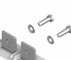
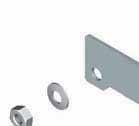
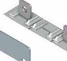
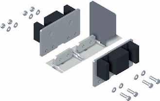
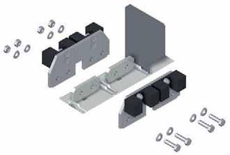
188 SIRCO PV UL 98B Load break switches for photovoltaic applications General Catalogue

 2 connectors per terminal with the connection kit 2729 1200. (3) 3 connectors per terminal with the connection kits 2729 1201 and 2709 1202.")

189 SIRCO PV UL 98B Load break switches for photovoltaic applications Frame size Rating max (A) Numbrer and size of cables Max. number of connections per terminal Type of cable Quantity Reference (1) Order a fan out kit reference for connecting 3 connectors per terminal (6 in total for the switch). (2) 2 connectors per terminal with the connection kit (3) 3 connectors per terminal with the connection kits and Copper bar connection kits To allow connection between the two power terminals from a same pole Top or bottom flat connection Quantity to Frame size Rating (A) Figure order per pole Number of terminals Reference Top or bottom edgewise connection Quantity to Frame size Rating (A) Figure order per pole Number of terminals Reference General Catalogue
190 SIRCO PV UL 98B Load break switches for photovoltaic applications Pole connections in series B4B5 2 P B6B7 4 P Connected to earth Not connected to earth Connected to earth Not connected to earth Not connected to earth () () () () () 1 () () 1 () () 1 () () 1 () () () 1 () () B7 DS 8 P Connected to earth Not connected to earth B B () B4B5 3 P () 1 () A Connected to earth 1 () () 1 () Not connected to earth () () () () A B6 DS B7 DS 8 P Connected to earth () A () 1 1 () B () A. Front switch. B. Rear switch. 1. Circuit 1. Not connected to earth () A () () 1 B () A. Front switch. B. Rear switch. 1. Circuit 1. General Catalogue
191 SIRCO PV UL 98B Load break switches for photovoltaic applications B4 DS 4P Connected to earth B Not connected to earth () () () () B B5 4P Connected to earth Not connected to earth () 1 2 () () () A () () A () () () () 1 1 () A () B5 DS B7 DS 8P Connected to earth () B5 DS 6P A Connected to earth () () 1 () 2 2 () B () B () () () 1 1 () Not connected to earth () () 1 Not connected to earth () A () () A () () 2 () () 2 () B 2 () () () B () () () () () () () () () () 1 A. Front switch. B. Rear switch. 1. Circuit Circuit 2. () A () () () 2 () B () () A. Front switch. B. Rear switch. 1. Circuit Circuit 2. B5 DS 8P Connected to earth Not connected to earth () () () () B () () () () B () () () 1 2 A () () () () 3 4 () () () () () 1 2 A () () () 3 4 () A. Front switch. B. Rear switch. 1. Circuit Circuit Circuit Circuit General Catalogue
192 SIRCO PV UL 98B Load break switches for photovoltaic applications Characteristics UL 98B Rating (A) 100 A 200 A Number of Number of Number of circuits Rated voltage (A) pole(s) in series per polarity Number of pole(s) of the device Frame size (A) pole(s) in series per polarity Number of pole(s) of the device Frame size 1 circuit 1000 VDC P 2 P P 2 P 2 circuits P 2 P 1 P 2 P 2 circuits 1000 VDC P P P 1 P Connection terminals Mechanical characteristics Auxiliary contact IEC Rated current In 160 A 250 A Thermal current at 40 C (A) Thermal current at 50 C (A) Thermal current at 60 C (A) i imp Number of pole(s) in series per polarity Number of pole(s) of the device Number of pole(s) in series per polarity Number of pole(s) of the device Rated Utilisation Frame Frame Number of circuits voltage category (A) size (A) size 1 circuit 1000 VDC 2 P 2 P P 2 P 1 circuit 1500 VDC circuits 1000 VDC 2 P P P 1 P (1) Wwithout fuse during 50 ms. General Catalogue
193 SIRCO PV UL 98B Load break switches for photovoltaic applications UL 98B Rating 250 A 275 A Number of Number of Number of circuits Rated voltage (A) pole(s) in series per polarity Number of pole(s) of the device Frame size (A) pole(s) in series per polarity Number of pole(s) of the device Frame size 1 circuit 1000 VDC P 2 P 2 P 2 P B5 2 circuits 1 P 2 P P 2 P B5 2 circuits 1000 VDC P 2 P B5 1 P P B VDC P 8 P B P B5 8 circuits P 8 P B Connection terminals Mechanical characteristics Auxiliary contact IEC Rated current In 315 A 275 A Thermal current at 40 C (A) Thermal current at 50 C (A) Thermal current at 60 C (A) i imp Number of pole(s) in series per polarity Number of pole(s) of the device Number of pole(s) in series per polarity Number of pole(s) of the device Rated Utilisation Frame Frame Number of circuits voltage category (A) size (A) size 1 circuit 1000 VDC 2 P 2 P 2 P 2 P B5 1 circuit 1500 VDC B5 2 circuits 1000 VDC 2 P 2 P B5 1 P 1 P B VDC 2 P 8 P B5 1 P B5 8 circuits 1 P 8 P B5 (1) Without fuse during 50 ms. 208 General Catalogue
194 SIRCO PV UL 98B Load break switches for photovoltaic applications UL 98B Rating 325 A 350 A Number of Number of Number of circuits Rated voltage (A) pole(s) in series per polarity Number of pole(s) of the device Frame size (A) pole(s) in series per polarity Number of pole(s) of the device Frame size 1 circuit 1000 VDC 2 P 2 P B5 2 circuits P 2 P B5 2 circuits 1000 VDC 2 P B5 B P B VDC 2 P 8 P B5 2 P 8 P B P B P B5 8 circuits P 8 P B P 8 P B Connection terminals Mechanical characteristics Auxiliary contact IEC Rated current In 400 A 500 A Thermal current at 40 C (A) Thermal current at 50 C (A) Thermal current at 60 C (A) i imp Number of pole(s) in series per polarity Number of pole(s) of the device Number of pole(s) in series per polarity Number of pole(s) of the device Rated Utilisation Frame Frame Number of circuits voltage category (A) size (A) size 1 circuit 1000 VDC 2 P 2 P B5 2 circuits 1000 VDC 2 P B5 500 B5 1 P B VDC 2 P 8 P B P 8 P B5 1 P B5 1 P B5 8 circuits 1 P 8 P B5 1 P 8 P B5 (1) Without fuse during 50 ms. General Catalogue
195 SIRCO PV UL 98B Load break switches for photovoltaic applications UL 98B Rating 400 A 600 A Number of Number of Number of circuits Rated voltage (A) pole(s) in series per polarity Number of pole(s) of the device Frame size (A) pole(s) in series per polarity Number of pole(s) of the device Frame size 1 circuit 1000 VDC 2 P 2 P B5 2 circuits P 2 P B5 2 circuits 1000 VDC 2 P B5 8 P P B Connection terminals Mechanical characteristics Auxiliary contact IEC Rated current In 500 A 800 A Thermal current at 40 C (A) Thermal current at 50 C (A) Thermal current at 60 C (A) i imp Number of pole(s) in series per polarity Number of pole(s) of the device Number of pole(s) in series per polarity Number of pole(s) of the device Number of circuits Rated voltage Utilisation category (A) Frame size (A) Frame size 1 circuit 1000 VDC P 2 P B circuit 1500 VDC 500 B P 8 P 2 circuits 1000 VDC 1 P B P 1 P B5 (1) Without fuse during 50 ms. (2) 1200 VDC for B General Catalogue
196 SIRCO PV UL 98B Load break switches for photovoltaic applications UL 98B Rating 800 A 1200 A Number of Number of Number of circuits Rated voltage (A) pole(s) in series per polarity Number of pole(s) of the device Frame size (A) pole(s) in series per polarity Number of pole(s) of the device Frame size 1 circuit 1000 VDC circuits circuits 1000 VDC P P Connection terminals Mechanical characteristics Auxiliary contact IEC Rated current In 1000 A 1400 A Thermal current at 40 C (A) Thermal current at 50 C (A) Thermal current at 60 C (A) i imp Number of pole(s) in series per polarity Number of pole(s) of the device Number of pole(s) in series per polarity Number of pole(s) of the device Number of circuits Rated voltage Utilisation category (A) Frame size (A) Frame size 1 circuit 1000 VDC circuit 1500 VDC P 8 P P 8 P 2 circuits 1000 VDC P P (1) Without fuse during 50 ms. (2) Maximum 6 x 600MCM with fan out kit (3) 1200 VDC for B7. General Catalogue
197 SIRCO PV UL 98B Load break switches for photovoltaic applications UL 98B Rating Number of circuits Rated voltage (A) 2000 A Number of pole(s) in series per polarity Number of pole(s) of the device Frame size 1 circuit 1000 VDC P 8 P 10 Connection terminals Mechanical characteristics Auxiliary contact IEC Rated current In 2200 A Thermal current at 40 C (A) 2200 Thermal current at 50 C (A) 1850 Thermal current at 60 C (A) 1600 i 1200 imp 12 Number of pole(s) in Number of series per pole(s) of Frame Number of circuits Rated voltage Utilisation category (A) polarity the device size 1 circuit 1000 VDC P 8 P (1) Without fuse during 50 ms. (2) Maximum 6 x 600MCM with fan out kit General Catalogue
198 SIRCO PV UL 98B Load break switches for photovoltaic applications J1 J Ø 0.35 Ø 9 Ø 0.27 Ø 7 Y B Ø 0.43 Ø 11 K K1 H B B H H1 Ø 0.51 Ø 13 J2 J3 A C Frame size B5 B5 B5 No. of poles Unit A B C H H1 max. J J1 J2 J3 K K1 Y 2 P inches mm P inches mm inches mm inches mm J1 J Ø 0.35 Ø 9 Ø 0.27 Ø 7 Y C Y B4 DS Ø 0.43 Ø 11 K1 H B5 DS B K H H2 Ø 0.51 Ø 13 A J3 J2 H Frame size B5 B5 No. of poles Unit A B C H H1 H1 max. J J1 J2 J3 K K1 Y Y1 inches mm inches mm P inches mm General Catalogue
199 SIRCO PV UL 98B Load break switches for photovoltaic applications J C J1 Y Ø 0.41 Ø 10.5 H K2 K1 K B H Ø 0,35 Ø A H1 Frame size No. of poles Unit A B C H H1 J J1 K K1 K2 Y inches 1.10 mm C J J1 Y Y Ø 0.41 Ø 10.5 B K K1 H H A H1 Frame size No. of poles Unit A B C H H1 J J1 K K1 Y Y1 8 P inches mm General Catalogue
200 SIRCO PV UL 98B Load break switches for photovoltaic applications J1 J Y C Ø 0.41 Ø 10.5 C J1 J Y1 Ø 0.41 Ø 10.5 B K K H H H H2 K2 K B K1 H A H1 Frame size No. of poles Unit A B C H H1 H2 J J1 K K1 K2 Y inches mm A H1 Frame size No. of poles Unit A B C H H1 J J1 K K1 Y Y1 8 P inches mm General Catalogue
201 SIRCO PV UL 98B Load break switches for photovoltaic applications Handle type Front operation Direction of operation Door drilling S2 type Ø 3.07 Ø I Ø 1.46 Ø 37 4 Ø Ø B5 Front operation Handle type Direction of operation Door drilling S3 type Ø 3.07 Ø Ø 1.46 Ø Ø Ø General Catalogue
202 SIRCO PV UL 98B Load break switches for photovoltaic applications Front operation Handle type Direction of operation Door drilling S4 type I Ø3.07 Ø Ø Ø Ø 1.46 Ø 37 Front operation Handle type Direction of operation Door drilling V1 type I Ø Ø 6.5 Ø 1.22 Ø General Catalogue
203 SIRCO PV UL 98B Load break switches for photovoltaic applications Ø Ø 0.51 Ø Ø 0.51 Ø 13 R Ø 0.43 Ø Ø 0.51 Ø Ø 0.41 Ø Ø 0.41 Ø General Catalogue
204 SIRCO PV UL 98B Load break switches for photovoltaic applications All frames 100 to 250 A 100 to 250 A Ø Ø 0.4 Ø Ø General Catalogue


205 SIRCO M UL 508 Load break switches standards UL and CSA from 16 to 80 A The solution for Load break switches sircm_132_a sircm_133_a > Industrial control systems Rotary switch SIRCO M 3 x 80 A Toggle switch SIRCO M 3 x 80 A 2 auxiliary contacts Strong points > Positive break indication > Direct or external operation > Compact footprint > DINrail or base mounting > Wide range of accessories > Up to 8 pole or 4 pole MTS Conformity to standards (1) sircm_174_a Rotary switch SIRCO M 3 x 80 A sircm_175_a > IEC > UL 508 listed, Guide NLRV, File E > CSA C , class , File * (1) Product reference on request. Function SIRCO M UL / CSA are compact and modular nonfusible disconnect switches. They make and break under all types of load conditions and provide safe isolation for any low voltage circuit, especially for machine control circuits. General characteristics Positive break indication. Direct or external operation. Compact footprint. DINrail or base mounting. Wide range of accessories. Up to 8 pole or 4 pole MTS. UL 508 nonmetallic polycarbonate 4.4x enclosed SIRCO M > Enclosed SIRCO M switches allow safe control and disconnection of any motor application. sircm_003_a sircm_005_a_1_cat 220 General Catalogue
206 SIRCO M UL 508 Load break switches standards UL and CSA from 16 to 80 A UL 508 manual motor controller Suitable as motor disconnect References Rating (A) No. of poles Toggle switch (direct handle included) Rotary switch Direct handle External front and right side handles (4) Shaft for external handles Switched fourth pole module Auxiliary contacts Terminal shrouds Door mounting kit 16 A 3 P S00 type I 0 Black 3R, 12 (1) P A 3 P Red / Yellow 3R, 12 (1) P A 3 P A 3 P A 3 P Blue Black 4, 4X (1) 147D 1111 Red / Yellow 4, 4X (1) 147E 1111 S0 type I 0 Black 1, 3R, 12 (1) S00 and S0 type 150 mm 5.9 in mm 7.9 in mm 12.6 in (2) 1 P P P M type 1 AC NO NC AC 2 NC P (3) 3 P (3) A 3 P A 3 P Red / Yellow 1, 3R, 12 (1) Black 4, 4X (1) 148D 1111 Red / Yellow 4, 4X (1) 148E P P (3) 1P P (3) (1) Nema / UL type. (2) Please order the shaft guide: with the shaft. (3) Top and bottom. (4) There is no door interlocking when the switch is fitted on the side of the enclosure. General Catalogue

207 SIRCO M UL 508 Load break switches standards UL and CSA from 16 to 80 A UL 508 nonmetallic polycarbonate 4, 4X enclosed SIRCO M coff_368_a_1_cat Function Enclosed SIRCO M switches allow safe control and disconnection of any motor application. General characteristics Grey enclosure with red handle. Equipped with a 3 pole SIRCO M. 1 removable ground terminal. Possibility of adding 1 power pole and 1 auxiliary contact. Nema / UL type 1, 3R, 12, 4, 4X. Conformity to standards (1) > IEC > UL 508, Guide NLRV, file E > CSA C22.2#14, Class , file (1) Product reference on request. References Rating (A) No. of poles Enclosed switches Enclosure size Switched fourth pole module Unswitched neutral pole Unswitched protective ground module Auxiliary contacts Terminal shrouds 32 A 3 P Size 1 3 P Size 2 63 A 3 P Size 2 1 P P (1) 1 P (1) 1 P (1) 1 P (1) 1 P (1) M type 1 AC NO NC AC 2 NC P (2) 3 P (2) 1 P (2) 3 P (2) (1) Not UL. (2) Top and bottom. Configuration sircmul_012_a_1_cat Configuration of the auxiliary contacts for enclosed SIRCO M. 1. M type auxiliary contacts. 2. Additional pole. Dimensions (in / mm) 0.79 Ø Ø Size sircmul_007_a_1_x_cat Size 2 Ø 2.67 Ø sircmul_008_a_1_x_cat 222 General Catalogue
.")

208 SIRCO M UL 508 Load break switches standards UL and CSA from 16 to 80 A Accessories Direct operation handle Rating (A) Handle color Handle type Reference Blue M acces_277_a_2_cat External operation handle The handle locking function prevents the user from opening the door of the enclosure when the switch is in the ON position (only if the handle is fitted on the door). Opening the door when the switch is in the ON position is possible by defeating the interlocking function with the use of a tool (authorised persons only). The interlocking function is restored when the door is closed. Front and right side handles I 0 Rating (A) Handle color Handle type Nema / UL type Standard Reference Heavy duty Reference Black S00 3R, Red / Yellow S00 3R, Black S00 4, 4X 147D Red / Yellow S00 4, 4X 147E Black S0 1, 3R, Red / Yellow S0 1, 3R, Black S0 4, 4X 148D Red / Yellow S0 4, 4X 148E Black S01 3R, F Red / Yellow S01 3R, G Black S01 4, 4X 140D D Red / Yellow S01 4, 4X 140E E 2911 (1) Not UL. Front handle for transfer switches I 0 II Rating (A) Handle color Handle type Nema / UL type Reference Black S00 IP (1) Front handle for transfer switches I III II Rating (A) Handle color Handle type Nema / UL type Reference Black S00 IP (1) M00 handle S00 handle S0 handle S01 handle acces_264_a_2_cat acces_279_a_2_cat acces_304_a_2_cat Shafts for external handle Standard lengths: 150 mm, 200 mm, 320 mm. Other lengths: please consult us. For 3 / 4 pole switches, shaft extensions for external front and side handle. For 6 / 8 pole switches and SIRCOVER M transfer switches. acces_280_a_2_cat For 3 / 4 pole Length Ratg (A) Handle type (in) (mm) Reference S S S S S S For 6 / 8 pole Length Rating (A) Handle type (in) (mm) Reference S S S General Catalogue
 No.")
209 SIRCO M UL 508 Load break switches standards UL and CSA from 16 to 80 A Accessories (continued) Shaft guide for external handle This accessory enables handle to engage extension shaft with a misalignment of up to 15 mm. Required for a shaft lenght from 320 mm. Handle type Reference S00 and S acces_260_a_2_cat Additional pole 4 th pole Rating (A) No. of poles Type Reference 16 1 P switched P switched P switched P switched P switched P switched (1) 80 1 P switched (1) (1) Not UL. Transforms: 3 pole SIRCO M load break switch into 3 pole SIRCOVER M transfer switch into a 4 pole. sircm_072_b_1_cat Solid neutral pole Rating (A) No. of poles Type Reference P unswitched (1) P unswitched (1) (1) Not UL. Transforms the 3pole switch into a 3pole solid neutral. N or PE N or PE Ground module Rating (A) No. of poles Type Reference P unswitched (1) P unswitched (1) Adds 1 protective ground module pole to the load break switch. N or PE N or PE N or PE N or PE sircm_078_a_1_gb_cat (1) Not UL. Terminal shrouds Top and bottom additional protection against direct contact with the terminals or connection parts. Perforation on each terminal cover enables remote thermographic inspection without dismantling. Rating (A) No. of poles Position Reference P top and bottom P top and bottom P top and bottom P top and bottom sircm_049_a_1_cat 224 General Catalogue
. Characteristics A300. Rating (A) No.")

210 SIRCO M UL 508 Load break switches standards UL and CSA from 16 to 80 A M type Auxiliary Contacts Prebreak and signaling of positions 0 and I by NONC or 2 NO Auxiliary Contacts. They can be mounted on the left or on the right side of the device. Max 4 Auxiliary Contacts per product (2 modules). Characteristics A300. Rating (A) No. of AC AC type Reference AC NO NC AC 2 NO sircm_081_a_1_x_cat sircm_075_b_2_cat Auxiliary contacts configurations for SIRCO M Conversion kit These accessories enable the assembly of 2 switches in order to achieve: 6 or 8 pole switches 3 or 4 pole open or close transition transfer switches. Rating (A) Type (1) Reference Load break switches 6 / 8 pole Transfer switch 3 / 4 pole (I 0 II) Transfer switch 3 / 4 pole (I III II) (1) Non UL. Conversion kit for 6 or 8 pole load break switches sircm_050_c_2_cat Conversion kit for 3 and 4pole transfer switches (I 0 II) or (I III II) sircm_086_b_1_cat sircm_097_b_2_x_cat Door mounting kit This kit enables direct mounting of the switch on the panel door or on the right or left side of the panel with S00 and S0 handles. The S0 and S00 external handles are quick and easy to install due to an internal locking nut mounted on the inside of the enclosure. Rating (A) No. of poles Reference / 4 P sircm_051_b_2_cat General Catalogue
211 SIRCO M UL 508 Load break switches standards UL and CSA from 16 to 80 A Characteristics Characteristics according to UL 508 / CSA22.2#14 suitable as motor disconnect General use rating (A) 16 A 20 A 25 A 32 A 40 A 63 A 80 A Short circuit rating at 600 VAC (ka) / / / 65 Type of fuse J J J J J J J Max fuse rating (A) / / / 60 Max. motor hp / FLA 3 ph motor max. 208 VAC 3 / / / / / / / VAC 5 / / / / / / / VAC 10 / / / / / / / VAC 10 / / / / / / / 41 Connection terminals Solid 1 wire #14 #10 #14 #10 #14 #10 #14 #10 #14 #10 #14 #10 #14 #10 Solid 2 wires 2 x #12 2 x #12 2 x #12 2 x #12 2 x #12 2 x #12 2x #12 Stranded 1 wire #14 #4 #14 #4 #14 #4 #14 #4 #14 #4 #14 #1 #14 #1 Stranded 2 wires 2 x (#14 #12) 2 x (#14 #12) 2 x (#14 #12) 2 x (#14 #12) 2 x (#14 #12) 2 x (#10 #6) 2 x (#10 #6) Auxiliary contacts Electrical characteristics A300 A300 A300 A300 A300 A300 A300 Mechanical characteristics Endurance (number of operating cycles) Operating torque (lbs.in/ Nm) 7 / / / / / / / General Catalogue
212 SIRCO M UL 508 Load break switches standards UL and CSA from 16 to 80 A Characteristics according to IEC Thermal current I th (40 C) 16 A 20 A 25 A 32 A 40 A 63 A 80 A Rated insulation voltage U i (V) Rated impulse withstand voltage U imp (kv) Rated operational currents I e (A) Rated voltage Utilization A / B (1) A / B (1) A / B (1) A / B (1) A / B (1) A / B (1) A / B (1) 415 VAC AC23 A / AC23 B 16 / / / / / / / VAC AC22 A / AC22 B 16 / / / / / / / VAC AC23 A / AC23 B 16 / / / / / / / VAC AC21 A / AC21 B 16 / / / / / / / VAC AC22 A / AC22 B 16 / / / / / / / VAC AC23 A / AC23 B 16 / / / / / / / 40 Operational power in AC23 (kw) At 400 VAC without prebreaking AC in AC23 (kw) (1)(2) At 500 VAC without prebreaking AC in AC23 (kw) (1)(2) At 690 VAC without prebreaking AC in AC23 (kw) (1)(2) Fuse protected shortcircuit withstand (ka rms prospective) Prospective shortcircuit current (ka rms) (3) Associated fuse rating (A) (3) Overload capacity (U e 415 VAC) Rated shorttime withstand current 0.3 s. I CW (ka rms) (3) Rated shortcircuit making capacity I cm (ka peak) (3) Connection Minimum Cu cable cross section (mm²) Maximum Cu cable section (mm 2 ) Tightening torque min / max (Nm) 2 / / / / / / / 3.85 (1) A / B: Category with index A = frequent operation Category with index B = infrequent operation. (2) The power value is given for information only, the current values vary from one manufacturer to another. (3) For a rated operating voltage Ue = 400 VAC. General Catalogue
213 SIRCO M UL 508 Load break switches standards UL and CSA from 16 to 80 A Dimensions (in / mm) 16 to 80 A Toggle operation Direct operation with handle F 2 1 M F 1 M sircm_052_b_1_gb_cat G F1 M5 T N AC F G Position for 1 switched fourth pole module (1 per device max.) or 1 unswitched neutral pole or 1 protective ground module or 1 auxiliary contact. 2. Position for 1 auxiliary contact only. Note: Maximum of 4 additional blocks. sircm_053_b_1_gb_cat F1 M5 T F1 N AC External front handle A B C E External side handle 2 1 F M J 1 D sircmul_002_c_1_gb_cat G N AC 0.35 F1 F T 8.8 M Position for 1 switched fourth pole module (1 per device max.) or 1 unswitched neutral pole or 1 ground module or 1 auxiliary contact. 2. Position for 1 auxiliary contact only. Note: Maximum of 4 additional blocks. Rating (A) Overall dimensions Terminal shrouds Switch body Switch mounting Connection Units D min D max E min E max AC F F1 G J M N T in mm in mm ø 2.79 ø 71 Direct front handle for 6 / 8pole load break switches or 3 / 4pole transfer switches sircm_055_c_1_gb_cat N G 2.67 F J 2 1 X M F External front handle for 6 / 8pole load break switches or 3 / 4pole transfer switches F1 F T T Position for 1 switched fourth pole module (1 per device max.) or 1 unswitched neutral pole or 1 ground module or 1 auxiliary contact. 2. Position for 1 auxiliary contact only. Note: Maximum of 4 additional blocks E ø 2.79 ø 71 Rating (A) Overall dimensions Switch body Switch mounting Connection Units E min E max F F1 F2 G J M N T X in mm in mm General Catalogue
214 SIRCO M UL 508 Load break switches standards UL and CSA from 16 to 80 A External handles dimensions (in / mm) 16 to 80 A Handle type Front operation Side operation Direction of operation Direction of operation Door drilling S00 type I I With 4 fixing screws With fixing nut Ø 3.07 Ø Ø Ø Ø 1.22 Ø Ø 0.89 Ø 22.5 poign_059_c_1_us_cat Handle type Front operation Side operation Direction of operation Direction of operation Door drilling S0 type Ø 2.80 Ø I 0 90 I Ø 1.22 Ø 31 With 4 fixing screws Ø Ø Ø 0.89 Ø 22.5 With fixing nut poign_060_a_1_us_cat Front operation Handle type Direction of operation Door drilling S00 type Transfer switches Ø 3.07 Ø I 90 0 or III 90 II With 4 fixing screws Ø 1.45 Ø Ø Ø 7 With fixing nut 0.53 Ø Ø poign_070_a_1_gb_cat Handle type S01 type Front operation Side operation Direction of operation Direction of operation Door drilling With 4 fixing screws I I Ø 3.07 Ø Ø 1.46 Ø Ø 7 4 Ø 0.28 poign_018_a_1_gb_cat General Catalogue

215 SIRCO M UL 98 Load break switches standards UL and CSA from 30 to 100 A The solution for Load break switches sircm_100_a_1_cat > Power distribution Strong points Function Rotary switch SIRCO M 3 x 100 A SIRCO M load break switches are compact switches. They make and break under on and off load conditions and provide safe isolation. These switches are extremely durable and are tested and approved for use in the most demanding applications. General characteristics Positive break indication. Touch safe. DIN rail or back platemounted. Direct or external operation handle. Specific characteristics Contact point technology. > Positive break indication > Touch safe > DIN rail or back platemounted > Direct or external operation handle > Contact point technology Conformity to standards (1) > IEC > UL 98, Guide WHTY, file E > CSA 22.2#4, Class , file (1) Product reference on request. * References UL 98 Load break switches Rating (A) No. of poles Switch body Direct handle External front and right side handles Shafts for external front and side handles Switched fourth pole module Unswitched neutral pole Ground module Auxiliary contacts Terminal shrouds 30 A 3 P A 3 P Blue S00 type I 0 Black 4, 4X 147D 1111 Red/Yellow 4, 4X 147E 1111 S0 type I 0 Black 4, 4X 148D mm 5.9 in mm 7.9 in mm 12.6 in (1) 1 P P P (2) 1 P (2) M type 1 AC NO NC M type 1 AC 2 NC P (3) 3 P (3) 100 A 3 P Red/Yellow 4, 4X 148E P (1) Shaft guide reference , is required for shaft length over 15.7 inches (400 mm). (2) Not UL. (3) Top and bottom. 230 General Catalogue

216 SIRCO M UL 98 Load breaks witches standards UL and CSA from 30 to 100 A Accessories Direct operation handle Rating (A) Handle colour Handle type Reference Blue M acces_283_a_2_cat M01 handle External operation handle The handle locking function prevents the user from opening the door of the enclosure when the switch is in the "ON" position (only if the handle is fitted on the door). Opening the door when the switch is in the "ON" position is possible by defeating the interlocking function with the use of a tool (authorised persons only). The interlocking function is restored when the door is closed. acces_279_a_2_cat Front and right side handles I 0 Rating (A) Handle colour Handle type Nema/UL type Reference Black S0 1, 3R, Red/Yellow S0 1, 3R, Black S0 4, 4X 148D Red/Yellow S0 4, 4X 148E Black S01 3R, F Red/Yellow S01 3R, G Black S01 4, 4X 140D Red/Yellow S01 4, 4X 140E 2111 S0 handle acces_304_a_2_cat S01 handle Shafts for external handle Standard lengths: 5.9 in / 150 mm, 7.9 in / 200 mm, 12.6 in / 320 mm. Other lengths: please consult us. For 3/4 pole switches, shaft extensions for external front and side handle. For 6/8 pole switches and SIRCOVER M transfer switches. acces_280_a_2_cat For 3/4 pole Length Rating (A) Handle type (inches) (mm) Reference S S S S S S General Catalogue
 No.")
 (1) Not UL. Adding one or two additional poles transforms a Load break switch from 3 poles to 4 poles.")
217 SIRCO M UL 98 Load breaks witches standards UL and CSA from 30 to 100 A Accessories (continued) Shaft guide for external handle This accessory makes shaft introduction easier with up to 15 mm misalignment. Required for a shaft length from 12.6 in / 320 mm. Handle type Reference S acces_260_a_2_cat Additional pole for SIRCO M 4 th pole Rating (A) No. of poles Type Reference 30 1 P switched P switched P switched Solid neutral pole Rating (A) No. of poles Type Reference P unswitched (1) (1) Not UL. Adding one or two additional poles transforms a Load break switch from 3 poles to 4 poles. Transforms the 3pole switch into a 3pole solid neutral. N or PE N or PE sircm_072_b_1_cat Ground module Rating (A) No. of poles Type Reference P unswitched (1) (1) Not UL. Adds 1 ground module pole to the load break switch. N or PE N or PE N or PE N or PE sircm_078_a_1_gb_cat Terminal shrouds Top and bottom additional protection against direct contact with the terminals or connection parts. 1 or 3 pole are available. Perforation on each terminal cover enables remote thermographic inspection without dismantling. Rating (A) No. of poles Position Reference P top and bottom P top and bottom sircm_049_a_1_cat M type auxiliary contacts Prebreak and Signalling of positions 0 and I by NONC or 2 NO auxiliary contacts. They can be mounted on the left or on the right side of the switch. Max 4 auxiliary contacts (2 modules). Characteristics A300. sircm_075_b_2_cat Rating (A) No. of AC AC type Reference AC NO NC AC 2 NO sircm_081_a_1_x_cat Auxiliary contacts configurations for SIRCO M 232 General Catalogue
218 SIRCO M UL 98 Load breaks witches standards UL and CSA from 30 to 100 A Characteristics Characteristics according to UL 98/CSA22.2#4 General use rating 30 A 60 A 100 A Shortcircuit rating at 480 VAC (ka) Short circuit rating at 600 VAC (ka) Type of fuse J J J Max fuse rating (A) Max. motor hp / FLA 3 ph motor max VAC 10 / / / VAC 20 / / / VAC 25 / / / 52 Max. motor hp / FLA 1 ph motor max. 120 VAC 2 / 24 3 / 34 5 / VAC 5 / / / 50 Connection terminals Solid 1 wire #12 #10 #12 #10 #12 #10 Stranded 1 wire #12 2/0 #12 2/0 #12 2/0 Mechanical characteristics Endurance (number of operating cycles) Operating torque (lbs.in/nm) 12.4 / / / 1.4 Auxiliary contacts Electrical characteristics A300 A300 A300 Characteristics according to IEC Thermal current I th at 40 C (A) 30 A 60 A 100 A Rated insulation voltage U i (V) Rated impulse withstand voltage U imp (kv) Rated operational currents I e (A) Rated voltage Utilisation category A (1) A (1) A (1) 400 VAC AC22 A VAC AC23 A VAC AC22 A VAC AC23 A Operational power in AC23 (kw) At 400 VAC without prebreak AC in AC23 (kw) (2)(3) At 500VAC without prebreak AC in AC23 (kw) (2)(3) At 690VAC without prebreak AC in AC23 (kw) (2)(3) Overload capacity (U e 415 VAC) Rated shortcircuit making capacity I cm (ka peak) (4) Connection Min. connection section/ (mm 2 ) Max. connection section/ (mm 2 ) (1) Category with index A = frequent operation. (2) A/B: Category with index A = frequent operation Category with index B = infrequent operation. (3) The power value is given for information only, the current values vary from one manufacturer to another. (4) For a rated operating voltage Ue = 400 VAC. General Catalogue
219 SIRCO M UL 98 Load breaks witches standards UL and CSA from 30 to 100 A Dimensions (in/mm) 30 to 100 A Direct operation with handle F M 1 2 sircm_056_d_1_gb_cat G N AC F1 T F M5 External front operation External side operation 1. Location for: 1 switched fourth pole module (1 per device max.) or 1 unswitched neutral pole or 1 protective earth module or 1 auxiliary contact. 2. Position for 1 auxiliary contact module only. Note: max 2 additional blocks E D 2 1 M F J D A B sircm_057_d_1_gb_cat G N AC ø F1 T F1 M Location for: 1 switched fourth pole module (1 per device max.) or 1 unswitched neutral pole or 1 protective earth module or 1 auxiliary contact. 2. Position for 1 auxiliary contact module only. Note: max 2 additional blocks. A. S01 handle B. S00 handle Rating (A) / Frame size / M3 Overall dimensions Terminal shrouds Switch body Switch mounting Connection D min D max E min E max AC F F1 G J M N T mm , ,4 26 in , , General Catalogue
220 SIRCO M UL 98 Load breaks witches standards UL and CSA from 30 to 100 A External handles dimensions (in/mm) 30 to 100 A Front operation Side operation Handle type Direction of operation Direction of operation Door drilling S0 type 90 I 90 I With 4 fixing screws Ø Ø With fixing nut Ø 2.80 Ø Ø 1.22 Ø Ø 0.89 Ø 22.5 poign_060_a_1_us_cat Handle type S01 type Front operation Side operation Direction of operation Direction of operation Door drilling With 4 fixing screws I I Ø 3.07 Ø Ø 1.46 Ø Ø 7 4 Ø 0.28 poign_018_a_1_us_cat General Catalogue
221 INOSYS LBS UL 98 Load Break Switches for AC applications Load break switches new The solution for > Emergency switching > Main switchboards > Distribution panels > Motor load breaks Strong points Function Reliability and guaranteed safety combined with low maintenance costs are vital when selecting components for integration in electrical systems. With its proven switching technology and tripping function, can be used for performing safe maintenance in the installation as well as emergency breaking. INOSYS LBS are multipolar load break switches which are available with integrated tripping function. They can be operated manually using the handle or remotely (via tripping coils) to disconnect part or all of the electrical installation. They make and break under load conditions, provide safety isolation for any low voltage circuits and are suitable for emergency switching. Advantages INOSYS LBS 3poles inosy_002_a.eps INOSYS LBS 3poles with tripping function > Highperformance switching in a compact footprint > Safe operation > Enhanced disconnection and isolation > Tripping function > Easy to install > Highly reliable solution Conformity to standards > IEC > UL 98 (1) Compatible with requirements: > IEC > IEC > NEC (1) Consult us. Highperformance switching in a compact frame INOSYS LBS switches integrate a patented technology that offers high switching capacity with optimum arc containment up to Safe operation Reliable position indication through visible contacts. The opening and closing of the switch is fully independent from the speed of operation, ensuring safe operation under all conditions. Enhanced disconnection and isolation ON, OFF and TRIP positions are stable: resistant to voltage fluctuations and external environmental constraints. Guaranteed disconnection in both OFF & Trip positions. Padlocking in OFF position available directly on the switch and on the external handle. Tripping function: flexible and robust Fully immune to external disturbances: no nuisance tripping. Shunttrip or undervoltage release Wide operating temperature range: Fast disconnection (<50 ms) emergency switching, compliant with installation standards. relay. Easy to install Mounting: back plate mounting either between poles or through the use of fixing pads. Free access to terminals for flexible wiring. Easy access without tools to integrate auxiliary contacts and tripping coil (both located within the switch footprint). Highly reliable solution Highperformance and guaranteed safety: the contacts opening and closing speed is fully independent of the handle operation. High temperature withstand: 236 General Catalogue

222 I I I I INOSYS LBS UL 98 Load Break Switches for AC applications from 100 to 600 A, up to 1000 VAC incorporating tripping function Machine emergency switching Building emergency switching Switchgear enclosure Local safety switch Incoming section O O O Network O Feeder output Machine control Red/yellow handle Motor sircm_021_f_en.ai INOSYS LBS inosy_094_a_en.ai Power electronics: UPS, backfeed, battery protection Mobile equipment INOSYS LBS UPS Distribution enclosure with automatic switching device INOSYS LBS Input Output Crane Aux mains Manual maintenance Site enclosure with a general break external handle Mains 1 Battery Mains 2 Output inosy_095_a_en.ai SIRCO Local manual operation Up to 1000 VAC with visible contact indication with or without tripping function from 125 to 5000 A General Catalogue
 Frame size No.")
223 INOSYS LBS UL 98 Load Break Switches for AC applications from 100 to 600 A, up to 1000 VAC incorporating tripping function Overview Shaft for external handle 6. Auxiliary contact 7. Tripping coil 8. Interphase barrier 9. Terminal shrouds 10. Terminal screens Holding insert 13. Terminal lugs References Rating (A) Frame size No. of poles Switch body (1) Switch with tripping function Switch without tripping function Other compatible accessories External External operation Tripping coil Switch body (1) operation (2) Aux. Contact Terminal screen (3) 100 F2 200 F A Shaft Shunt trip coil 87A Shaft P 85A A A S2 type handle S2 type handle Black A black P 85A D 2118 Undervoltage releases 87A A A Shaft Shaft 4P 85A A A S2L type handle S2L type handle Black 87A black P 85A AD A (1) The basic devices are delivered without accessories. (2) For external side operation on the left, please order the S2 handle reference 142A2111 for case sizes F2 and F3. Please consult us if you require a device with side operation on the right. (3) Compatible with the holding insert which can be fitted to lock the shrouds in place. 238 General Catalogue
224 INOSYS LBS UL 98 Load Break Switches for AC applications from 100 to 600 A, up to 1000 VAC incorporating tripping function Accessories include an escutcheon and are padlockable. External handles must be utilised with an extension shaft. Example of application As the handle is interlocked in the ON position the operator must safely disconnect and isolate the circuit prior to accessing the panel for maintenance procedures. Opening the door when the switch is in the ON position can only be done by defeating the interlocking function with the use of a dedicated tool (authorised persons only). The interlocking function is restored when the door is reclosed. S2 type handle acces_150_a_1_cat.eps Frame size Handle type Handle colour Degree of protection Reference F2 S2 Black 742F 2118 F2 S2 Black 742D 2118 F2 S2 Red 742G 2118 S2L (1) Black 74AF 2118 S2L (1) Black 74AD 2118 S2L (1) Red 74AG 2118 (1) S2L handles have an extended grip; please refer to the dimensions section. Frame size Handle type Handle colour Degree of protection Reference F2 S2 Black 142F 2111 F2 S2 Black 142D 2111 F2 S2 Red 142E 2111 S2L (1) Black 14AF 2111 S2L (1) Black 14AD 2111 S2L (1) Red 14AE 2111 (1) S2L handles have an extended grip; please refer to the dimensions section. Shaft for external handle Frame size Handle type Length (mm) Reference S2, S2L S2, S2L S2, S2L Other lengths: please consult us. Shaft for S2 and S2L type handle acces_401_a_1_cat Shaft guide for external handle To guide the shaft extension into the external handle. This accessory enables the handle to engage the shaft extension with a Required for a shaft length Description Reference Shaft guide General Catalogue

225 INOSYS LBS UL 98 Load Break Switches for AC applications from 100 to 600 A, up to 1000 VAC incorporating tripping function Accessories (continued) Alternative Stype handle cover colours For S2 and S2L type single grip handles. Handle colour Handle type To be ordered in multiples of Reference Light grey S2, S2L S2, S2L Other colours: please consult us. acces_198_a_1_cat Auxiliary contact The same auxiliary contact can be used to provide position and tripping information. The function of the auxiliary contact depends on where it is mounted on the mechanism. Characteristics IP2 with front operation. Frame size Connection type Type Reference Screw Screw Screw acces_402_a_1_cat Position Characteristics Auxiliary contact type Min. current (A) I th (A) Electrical characteristics per UL Standard 10 Low level 10 Position (prebreak) Trip Position POS 10 PRE TRIP POS Switch with tripping function Position (prebreak) PRE PRE Switch without tripping function 240 General Catalogue
226 INOSYS LBS UL 98 Load Break Switches for AC applications from 100 to 600 A, up to 1000 VAC incorporating tripping function Tripping coil Allows remote activation of the switch s tripping mechanism. Shunt trip and undervoltage release coils are available. Shunt trip coil Frame size Voltage (V) Reference Other voltage ratings available, please consult us. Undervoltage release Maximum one tripping coil per switch. Safe and easy coil replacement by using standard tools. Frame size Voltage (V) Reference Other voltage ratings available, please consult us. Shunt trip coil acces_404_a_1_cat Characteristics Shunt trip coils AC type (±10%) 24 VAC 48 VAC 110 VAC 230 VAC DC type (5% 20%) 24 VDC 48 VDC 110 VDC 230 VDC Inrush consumption (A), <10ms 0.78 Max supply time 2 s. Undervoltage release AC type 24 VAC 48 VAC 110 VAC 230 VAC n DC type 24 VDC 48 VDC 110 VDC 230 VDC n 1.4 Holding: up to 85% x Un Release: < 35 to 70% x Un General Catalogue
227 INOSYS LBS UL 98 Load Break Switches for AC applications from 100 to 600 A, up to 1000 VAC incorporating tripping function Accessories (continued) Terminal screen Provides top and bottom protection against direct contact with terminals or connection parts. Advantages Perforations for thermographic inspection. Mounting requires holding inserts (supplied with the terminal screens). Frame size No. of poles Position Reference (1) F2 Top and bottom F2 4 P Top and bottom Top and bottom P Top and bottom (1) Each reference comprises 2 terminal screens for top and bottom protection. acces_408_a_1_cat Holding insert Frame size Pack (unit) Reference acces_409_a_1_cat This accessory enables simple onesided connection to the power terminals. It can be mounted on either side of the terminal for front or rear connection. Frame size Pack (unit) Reference F F Allows connection of voltage sensing or power cables, with faston connection. Frame size Pack (unit) Reference F acce_412_a_1_cat 242 General Catalogue
228 INOSYS LBS UL 98 Load Break Switches for AC applications from 100 to 600 A, up to 1000 VAC incorporating tripping function General use rating (A) 100 A 200 A 400 A 600 A Frame size F2 F2 F3 F Type of fuse J J J J Max. fuse rating (A) Max motor hp / FLA 3 ph motor max Max. motor hp / DC FLA motor Connection terminals 1 AWG 250 kcmil 2 x 250 kcmil 2 x 500 kcmil Mechanical characteristics Endurance (number of operating cycles) Auxiliary contacts Electrical characteristics Thermal current I th (40 C) 160 A 250 A 400 A 630 A Frame size F2 F2 F3 F Rated impulse withstand voltage U imp Rated operational currents I e (A) Rated voltage Utilisation category A (1) A (1) A (1) A (1) Connection x x 150 Operational power in AC23 (kw) (2) Overload capacity (Ue 415 VAC) Rated shortcircuit making capacity Icm (ka peak) (1) Category with index A = frequent operation. (2) Note that these values may slightly vary depending on type and manufacturer of motors. General Catalogue
229 INOSYS LBS UL 98 Load Break Switches for AC applications from 100 to 600 A, up to 1000 VAC incorporating tripping function INOSYS LBS with tripping function J2 J J3 B 1.77 / 45 = = 9.84 / 250 = = J5 J6 P2 B1 = = J8 J P1 P 1.96 / / / / 126 A / / Interphase barrier. 2. Terminal shrouds. inosy_080_a_1_x_cat.ai Connection terminal F2 Connection terminal F A J Rating (A) Frame size No. of poles 3 P 4 P 3 P 4 P F2 in 8.15 mm in mm Rating (A) Frame size B B1 J2 J3 J5 J6 J7 J8 P P1 P F2 in mm in mm General Catalogue
230 INOSYS LBS UL 98 Load Break Switches for AC applications from 100 to 600 A, up to 1000 VAC incorporating tripping function INOSYS LBS without tripping function J8 B 1.77 / 45 = = 6.22 / 158 = = J5 J6 P2 B1 = = J J2 J J3 P1 1. Interphase barrier. P / / / 126 A / / Terminal shrouds. inosy_081_a_1_x_cat.ai Connection terminal F Connection terminal F A J Rating (A) Frame size No. of poles 3 P 4 P 3 P 4 P F2 in mm in mm Rating (A) Frame size B B1 J2 J3 J5 J6 J7 J8 P P1 P F2 in mm in mm General Catalogue
231 INOSYS LBS UL 98 Load Break Switches for AC applications from 100 to 600 A, up to 1000 VAC incorporating tripping function F2 frame size Handle type Front operation Direction of operation Door drilling S2 type with trip 0 40 Ø 78 Reset Trip 4 Ø I Ø poign_057_a_1_gb_cat.eps Handle type S2 type Front operation Direction of operation 0 Door drilling 40 Ø Ø I Ø Handle type Front operation Direction of operation Door drilling S2L type with trip 0 40 Ø 78 Reset Trip 4 Ø 7 I Ø 37 Handle type S2L type Front operation Direction of operation 0 Door drilling 40 Ø Ø 7 I Ø General Catalogue

232 INOSYS LBS UL 98 Load Break Switches for AC applications from 100 to 600 A, up to 1000 VAC incorporating tripping function Mounting orientation inosy_098_a.psd General Catalogue
SIRCO M and MV Universal load break switches from 16 to 160 A
 SRCO M and MV from 16 to 16 A The solution for Load break switches sircm_99_a > Main incoming load break > Distribution load break > Machine control > Local safety load break sircm_13_a 4 pole SRCO MV
An innovative technology
 The range An innovative technology Description The new are load break switches that combine attractive style and optimised features due to their innovative design. This range, dedicated to industrial applications,
SIRCO MV PV Load break switches for photovoltaic applications for use up to 1000 VDC from 63 to 80 A
 Load break switches SIRCO MV PV sircm-pv_010_a_1_cat The solution for > Residential buildings > Buildings > Solar parks Strong points SIRCO MV PV 1000 V - 80 A direct operation > Modular device > Patented
Non-fusable disconnect switches standards UL and CSA from 16 to 100 A
 Non-fusible disconnect switches sircm_132_a sircm_133_a The solution for > Industrial control systems Rotary switch SIRCO M 3 x 80 A Toggle switch SIRCO M 3 x 80 A + 2 auxiliary contacts Competitive advantages
SIRCO M UL 508 Non-fusible disconnect switches standards UL and CSA from 16 to 100 A
 Non-fusible disconnect switches SRCO M UL 58 sircm_132_a sircm_133_a The solution for > ndustrial control systems Rotary switch SRCO M 3 x 8 A Toggle switch SRCO M 3 x 8 A + 2 auxiliary contacts Strong
SIRCO UL98 Load break switches standards UL and CSA 100 to 1200 A
 The solution for Load break switches sirco-ul_022_b_1_cat > Power distribution. Strong points sirco_093_b_1_cat SIRCO 3 x 200 A > Reliability. > Safety of property and personnel. > Simplicity. > Easy assembling.
SIRCO PV IEC Load break switches for photovoltaic applications from 100 to 3200 A, up to 1500 VDC
 SIRCO PV IEC 609473 The solution for Load break switches > Combiner box > Recombiner box > Inverter sircopv_058_a_1_cat sircopv_059_a_1_cat Strong points Function SIRCO PV are manually operated multipolar
SIRCO PV IEC Load break switches for photovoltaic applications from 100 to 3200 A, up to 1500 VDC
 Load break switches SIRCO PV IEC 609473 new The solution for > Combiner box > Recombiner box > Inverter sircopv_058_a_1_cat sircopv_059_a_1_cat Strong points Function SIRCO PV are manually operated multipolar
SIRCO PV UL98B Load break switches for photovoltaic applications from 100 to 2000 A - up to 1500 VDC
 Load break switches sircopv_058_a cat SIRCO PV UL98 from 00 to 2000 up to 500 VDC sircopv_059_a cat Strong points > Patented switching technology. > Positive break indication. > Up to 000 VDC as per characteristics
SIRCO UL98 Non-fusible switches standards UL and CSA 100 to 1200 A
 Non-fusible disconnect switches SIRCO UL98 Non-fusible switches standards UL and CSA sirco-ul_022_b_1_cat The solution for > Power distribution sirco_093_b_1_cat SIRCO 3 x 200 A Strong points > Reliability
SIRCO PV Load break switches for photovoltaic applications for use up to 1500 VDC from 100 to 3200 A
 Load break switches new SRCO-pv_023_a_1_cat The solution for > Residential buildings. > Buildings. > Solar parks. Strong points Function SRCO PV are manually operated multipolar load break switches. They
FUSERBLOC Fuse combination switches with rear connection for industrial fuses up to 400 A
 Fuse protection fuser_737_a_1_cat.eps fuser_738_a_1_cat.eps The solution for > Motor load break > Protection of industrial processes FUSERBLOC REAR / FRONT connections 3 x 250 A fuser_739_a_1_cat.eps Strong
125 to 4000 A. Functions. Conformity to standards. Approvals and certifications (1) General characteristics. Available on request
 General characteristics. Available on request") 125 to 4000 A sirco_353_a_1_cat sirco_296_a_1_cat sirco_300_b switches are manually operated or motorised multipolar load break switches. They break on and off under load and provide safety isolation for
125 to 4000 A sirco_353_a_1_cat sirco_296_a_1_cat sirco_300_b switches are manually operated or motorised multipolar load break switches. They break on and off under load and provide safety isolation for
SIRCOVER. Manual Transfer Switching Equipment from 125 to 3200 A. Transfer switches. Function. Advantages. The solution for.
 Transfer switches svr_151_a The solution for > Manufacturing > Power distribution SIRCOVER 250 Strong points svr_214_a > Complete range > Easy to connect > Stable positions > On-load switching Conformity
FUSERBLOC Fuse combination switches for industrial fuses up to 1250 A
 Fuse protection fuser_548_a cat The solution for > Motor load break. > Protection of industrial cabinet. FUSERBLOC 6 to 25 A Strong points fuser_52_a cat Function FUSERBLOC 2 to 4 A FUSERBLOC are manually
FUSERBLOC Fuse combination switches for industrial fuses up to 1250 A
 Fuse protection fuser_548_a_1_cat The solution for > Motor load break > Protection of industrial processes FUSERBLOC 63 to 125 A Strong points fuser_532_a_1_cat Function FUSERBLOC 32 to 4 A FUSERBLOC are
SIRCOVER. Manual transfer switches from 125 to 3200 A. Transfer switches. Function. Advantages. The solution for. Strong points
 Transfer switches svr_151_a The solution for > Manufacturing industry > Power distribution SRCOVER 2 Strong points > complete range > Easy connections > Stable positions svr_125_a_1_cat Bypass TS 0 Conformity
ATyS S - ATyS d S Remotely operated Transfer Switching Equipment from 40 to 125 A
 Transfer switches The solution for > Genset < 90 kva > Heating systems > Climate control > Ventilation systems > Telecommunications atys-s_018_a Strong points Function products are 4 pole remotely operated
SIRCO PV UL98B Load break switches for photovoltaic applications from 100 to 2000 A, up to 1500 VDC
 Load break switches sircopv_058_a cat SIRCO PV UL98 new sircopv_059_a cat The solution for > Combiner box > Recombiner box > Inverter Function SIRCO PV UL98 non fusible disconnect switches are heavy duty
FUSOMAT Visible breaking and tripping fuse switches from 250 to 1250 A
 Fuse protection The solution for > Motor load break > Protection of industrial cabinet > Electrical distribution fusom_063_b_1_cat Strong points > Tripping upon overload > High breaking capacity > Improved
What you need to know. Â Conformity to standards
 SIRCO PV Load break switches for solar applications sirco_343_a_1_cat  What you need to know A solar electrical installation is an application that requires switching devices fully meet the needs of operational
SIRCOVER and SIRCOVER BY-PASS. Changeover switches with fully visualised breaking from 125 to 3200 A. 274 General Catalogue SOCOMEC
 and Manual Changeover Switches BY-PSS appli_114_a svr_099_b_1_cat svr_059_a_1_cat Changeover switches with fully visualised breaking from 125 to 3200 Function products are manually operated multipolar
ATyS d M Remotely operated Transfer Switching Equipment from 40 to 160 A
 ATyS d M Remotely operated Transfer Switching Equipment Transfer switches new The solution for > Applications with an external ATS/AMF controller > Building Management Systems (BMS) atys-md_002_b_1_cat
ATyS t M - ATyS g M Automatic Transfer Switching Equipment from 40 to 160 A
 TyS t M - TyS g M utomatic Transfer Switching Equipment Transfer switches new The solution for > High Rise uildings > Data centre > Healthcare buildings TyS g M I-0-II P atys-mg_001_b_1_cat Function TyS
ATyS. 63 to 3200 A. Functions. Conformity to standards. General characteristics. Changeover switches. Functions
 to 00 A Accessories Enclosed Characteristics M e atysm_007_a cat M s atysm_0_a cat products are and 4pole switches remotely controlled by volt free contacts ( ) or automatic transfer switches ( ). They
SIDERMAT Load break switches for power distribution from 250 to 1800 A with tripping function
 The solution for Load break switches sdmat_066_a cat > Main switchboard > Distribution panel > Motor load break unction SIDERMT 4 x 630 External front operation SIDERMT are manually operated 3 or 4 pole
Switching, control and protection solutions for solar applications
 Switching, control and protection solutions for solar applications continuous performance www.socomec.com Summary SIRCO M PV Manually operated modulable and modular switches p. 4 SIRCO MV PV Manually
CATALOGUE MARINE APPLICATIONS. Energy performance solutions
 CATALOGUE MARINE APPLICATIONS Energy performance solutions 2017 2018 Marine Certifications Our certified products As an independent manufacturer, we, at Socomec are committed to adapting the range and
sirco-ul_004_b_cat 100A to 2000A - 600VDC and 1000VDC UL98B Listed
 site_317_a sirco-ul_22_b_cat sirco-ul_4_b_cat 1A to 2A - 6VDC and 1VDC UL98B Listed  Function non fusible disconnects are heavy duty switches that break and make 6VDC or 1VDC photovoltaic circuits on
Contents. Volume 5 Motor Control and Protection CA E December
 Rotary Disconnects.2 R5 Series Non-Fusible 16 80A Product Description R5 Series (UL 508 listed) products are manually operated modular switches. Load break switching and isolation provide safety solutions
Motorised and automatic transfer enclosed switchess
 s Integrated products and solutions coff_538_a.eps atysm_251_b_1_cat.eps The solution for > igh-rise buildings > Data centers > Energy generation > ealthcare buildings > Banks and insurance companies >
ATyS range ATyS r, ATyS d, ATyS t, ATyS g, ATyS p from 125 to 3200 A
 Transfer switches Accessories Terminal shrouds IPX protection against direct contact with terminals or connecting parts. Advantages Perforations allow remote thermographic inspection without the need to
SIRCOVER UL1008/98 Changeover switches standards UL and CSA 100 to 1200 A
 Conformity to standards (1) Changeover switches svr-ul_14_b_1_cat > EC 6947-3 > UL98, Guide WHTY, file 1138 > UL18, Guide WPYV, file 31792 > CSA 22.2#4, Class 4651-2 (1) Product reference on request. svr_136_a_2_cat
FUSERBLOC Fuse combination switches for industrial fuses up to 1250 A
 fuser_548_a_1_cat fuser_532_a_1_cat fuser_539_a_1_cat FUSERBLOC from 25 to 32 A FUSERBLOC from 630 to 1250 A FUSERBLOC from 32 to 400 A Function FUSERBLOC are manually operated multipolar fuse combination
C60H-DC. C curve IEC Direct current (DC) Breaking capacity (Icu) according to IEC Type 1P 110 V 220 V 250 V 440 V 500 V
 Breaking capacity (Icu) according to IEC Type 1P 110 V 220 V 250 V 440 V 500 V") DC circuit supplementary protectors for feeders / distribution systems C60H-DC C curve DB123430 DB123525 DB405571 IEC 60947-2 PB107193-34.eps PB107194-34.eps The C60H-DC supplementary protectors are used
DC circuit supplementary protectors for feeders / distribution systems C60H-DC C curve DB123430 DB123525 DB405571 IEC 60947-2 PB107193-34.eps PB107194-34.eps The C60H-DC supplementary protectors are used
25A 25A 32A 40A 40A 63A 63A 80A
 ISDC Compact Range 25A - 200A Control Panel Isolation Equipment Craig & Derricott has ranges of Switch-Disconnectors, Fuse Combination Units and Changeover Isolators for panel mounting ranging from 25A
Enclosed DC rated switch-disconnectors OTDCP from 16 to 32 Amperes
 Protection and Connection Enclosed DC rated switchdisconnectors OTDCP from 16 to 32 Amperes Enclosed OTDC switches from 16 to 32 Amperes meet the demanding requirements of photovoltaic applications. Enclosed
FUSERBLOC CD. The universal Fuse Combination Switch FROM 20 TO 1250 A. Industrial Switching & Protection Systems
 FUSERBLOC CD The universal Fuse Combination Switch FROM 20 TO 1250 A SOCOMEC GROUP SWITCHING PROTECTION & UPS Industrial Switching & Protection Systems SWITCHING FUSERBLOC CD THE UNIVERSAL FUSE COMBINATION
Vistop TM isolating switches 63 to 160A
 DX 3 - IS main switches 16 to 125A Vistop TM isolating switches 63 to 160A 225 15 225 18 4 064 00 4 064 59 Pack Cat. No. Main switches AC 22 A category as per EN607-3 Grey handle Accept 1 signalling auxiliary
Safety enclosures Normal atmospheres steel enclosure from 50 to 1600 A
 Integrated products & solutions The solution for > Iron and steel industry > Cement plants > Paper mills > Sawmills > Hydraulic power packs > Automotive > Mining coff_436_a coff_434_a Strong points Function
PowerLine OS Switch Fuses A, 690V
 Technical Brochure PowerLine OS Switch Fuses 20...160 A, 690V Brochure OS 10 GB 99-04 9902CD04 ABB Control New Switch Fuse Range 2 3 Total user safety Total user safety Fuse carriers fully IP20 protected
Integrated products & solutions
 2017 2018 CATALOGUE EXTRACT Integrated products & solutions Enclosed switching, protection and metering systems Contents An independent manufacturer................................................. Expert
CATALOGUE. Solutions for Power, Control & Safety
 CATALOGUE Solutions for Power, Control & Safety 2015 Contents An independent manufacturer... p.4 Four key applications: the benefit of a specialist... p. 5 A cutting-edge laboratory... p. 6 Socomec in
Safety enclosures. 482 General Catalogue SOCOMEC. Safety enclosures
 coff_163_a_1_cat coff_156_b_1_cat Function equipped with SOCOMEC switches provide emergency breaking, breaking for mechanical maintenance and safety isolation in the vicinity of any low voltage final circuit.
DCX-M. changeover switches ->CATALOGUE PAGES INSIDE THE GLOBAL SPECIALIST IN ELECTRICAL AND DIGITAL BUILDING INFRASTRUCTURES
 DCX-M changeover switches ->CATALOGUE PAGES INSIDE THE GLOBAL SPECIALIST IN ELECTRICAL AND DIGITAL BUILDING INFRASTRUCTURES FOR COMMERCIAL BUILDINGS AND DCX-M In = 63 A Quality & design CONFORM TO EN/IEC
SENTRON Switching and Protection Devices Switch Disconnectors
 SENTRON Switching and Protection Devices Switch Disconnectors /2 Introduction 3K, 3KE, 3LD Switch Disconnectors 3K, 3KE Switch Disconnectors up to 1000 /4 General data /8 Floor mounting 3LD Main and EMERGENCY-STOP
LOCAL SWITCH-DISCONNECTORS STANDARD DUTY, TYPE RDMP, 20-63A, IP65, 2-8 POLES TECHNICAL DATA
 LOCAL SWITCH-DISCONNECTORS STANDARD DUTY, TYPE RDMP, 20-63A, IP65, 2-8 POLES Complying with BSEN60947 and IEC 408 the RDMP range of rotary cam switches are suitable for on load switching of general distribution
Non-fusible. Non-fusible disconnect switches 16A 3150A, 600VAC A, 1000VDC. International acceptance. Disconnect switches.
 disconnect 16A 31A, 0VAC 200-0A, 1000VDC Disconnect Disconnect ABB SwitchLine includes 16 different amperage sizes from 16A to 31A. The basic construction provides flexibility, safety, and high performance
Contact gap 7 mm (norm >5.5 mm) ÿ IN ENCLOSURE. ÿ WITH CLUTCH DRIVE
 ÿ IN ENCLOSURE. ÿ WITH CLUTCH DRIVE") Switch disconnectors A modular and flexible range Contact gap 7 mm (norm 5.5 mm) Reversible terminal feature ÿ IN ENCLOSURE - Degree of protection: up to IP 66 - For 25A to 100A size switches (see Ithe
Switch disconnectors A modular and flexible range Contact gap 7 mm (norm 5.5 mm) Reversible terminal feature ÿ IN ENCLOSURE - Degree of protection: up to IP 66 - For 25A to 100A size switches (see Ithe
Protection components
 Presentation, characteristics Presentation 1 2 3 motor circuit-breakers are 3-pole thermal-magnetic circuit-breakers standards IEC 60947-2 and IEC 60947-4-1. Connection These circuit-breakers are designed
Products and solutions for photovoltaic applications
 Products and solutions for photovoltaic applications Components for string and interface control panels Switch disconnectors Surge protection devices Fuse holders The range of LOVATO Electric components
SWITCH DISCONNECTORS PLANET -SWITCH.
 SWITCH DISCONNECTORS 6A to 600A ratings Versions: direct operating handle, door coupling and in housing Wide range of accessories Types for photovoltaic applications up to 50A. PLANET -SWITCH SEC. PAGE
LOAD BREAK SWITCHES. Ensto Compact
 LOAD BREAK SWITCHES Ensto Compact Ensto Enclosures and Components Ensto also offers enclosed switches; being assemblies of Ensto Cubo enclosures and load break switches. Ensto is an international industrial
LV switch-disconnectors. Interpact Merlin Gerin 40 to 2500 A. Catalogue. We do more with electricity
 LV switch-disconnectors Catalogue Merlin Gerin 40 to 2500 A We do more with electricity LV switch-disconnectors The various low-voltage applications 2 from 40 to 2500 A 4 Compact from 80 to 1250 A 5 Masterpact
General information about motor protection
 Application guide General information about motor protection Typical construction of a motor starter Disconnect Switch UL 98 - UL489 CSA C22.2 # 4 CSA C22.2 # 5 Fuses SIRCO Non-Fusible Disconnect Switch
Switches Section 1. Load Break Switches. Accessories for Load Break Switches. 4 Pole Part Price Each Reference
 Load Break Switches According to BS EN60947-3 High Thermal & Dynamic Strength Fully rated suitable for distribution & motor loads Auxiliary contacts also available Fully Visible Breaking Arduous categories
SIRCOVER Manual transfer switching equipment for source changeover applications from 63 to 3200A
 2017 CTLOGUE extract SIRCOVER Manual transfer switching equipment for source changeover applications from 63 to 3200 Transfer switches svr_207_a.eps svr_208_a.eps The solution for > Manufacturing > Power
Enclosed switches. from 20 to 1600 A
 Enclosed switches from 20 to 1600 A Why do you need an enclosed switch? Switchgear systems are an essential part of your electrical system. Present at all levels of your electrical distribution, they allow
Siemens AG Switch Disconnectors SENTRON. Configuration. Edition 10/2015. Manual. siemens.com/lowvoltage
 SENTRON Configuration Manual Edition 10/2015 siemens.com/lowvoltage 2 Introduction LD main control and EMERGENCY-STOP switches up to 250 A 4 Introduction 7 Front mounting 10 Floor mounting 11 Distribution
Miniature Circuit Breaker
 Introduction - Miniature Circuit Breaker (MCB) SALIENT FEATURES SALIENT FEATURES Standards MCBs conform to the latest standard IS 8828: 1996/IEC: 898 1995 Mid-Trip Position The Mid trip position of the
A compact range of Switch-Disconnectors with the capacity to add auxiliary and neutral block options to the basic load break switch block.
 PNE ISOTORS Craig & Derricott has a range of products designed specifically for control panel and switchboard construction. Most panels require a means of electrical isolation and the can offer variants
Transfer switching solutions
 CATALOGUE EXTRACT Transfer switching solutions from 40 to 6300 A 2018 Contents The SOCOMEC Group... Security and reliability for your transfer applications... Remotely operated and Automatic Transfer
Switch disconnectors
 Selection Load break switch disconnectors type LK3, 40-120 A Selection guide for 3 and 4-pole switch disconnectors General The LK3 range of switch disconnectors (lth: 40 A to 120 A) is designed for use
3 - Protection components Motor circuit-breakers
 Contents 0 - Protection components Motor circuit-breakers protection components for the motor protection Thermal-magnetic motor circuit-breakers Selection guide..............................................page
Low voltage Direct Current Network. Compact NSX DC PV. Circuit breakers and switch disconnectors for solar application.
 Low voltage Direct Current Network Compact NSX DC PV Circuit breakers and switch disconnectors for solar application Catalogue 2012 Compact NSX DC PV A complete DC offer for solar application from 80
 15 16 MCCBs for Power Distribution Technical Specification Frame 100A 250A 250A 400A 400A 630A 800 / 1000 / 1250 Type C DN0-100 D DN1-250 N DN2-250 D N S H DN3B-400 DN3-400 D N D N S V DN3-630 DN4-1250
Switch Disconnectors
 Switch Disconnectors Reversible terminals allow the same switch body to be used in both front & rear mount applications 25A - 32A - 50A - 63A - 80A - A versions available Neutral pole, additional poles
Load Break Disconnect Switches FSLBS
 Load Break Disconnect Switches FSLBS UL 508 Non-Fused Load Break Switches The FSLBS Load Break Switch is a newly designed industrial-grade switch capable of making or breaking loads up to 600V. It is suitable
Non-Fused Load Break Switches FSSC, SX, SXDC, SC
 UL 98 Non-Fused Load Break Switches Mersen disconnect switches are extremely durable, manually operated, non-fused disconnect switches. These heavy-duty switches are designed with the most up-todate disconnect
DPX Thermal magnetic and trip-free switches DPX 3 -I 160
 87045 LIMOGES Cedex Phone :+33 05 55 06 87 87 Fax :+33 05 55 06 88 88 DPX 3 160 CONTENTS PAGES 1. USE 1 2. RANGE 1 3. DIMENSIONS 1 4. OVERVIEW 2 5. ELECTRICAL AND MECHANICAL CHARACTERISTICS 3 6. CONFORMITY
LOAD BREAK SWITCHES AND SWITCH FUSES
 easy to install LOAD BREAK SWITCHES AND SWITCH FUSES Sixty years of innovation in developing and producing high-quality switches When Mr Kauko Hyryläinen founded KATKO in 1941, one of his key targets
Selection Guide Motor Control Device Solutions
 Selection Guide Motor Control Device Solutions Expect more and get it from c3controls. Our portfolio of Motor Control Devices consists of worldclass products designed and manufactured to meet your requirements
Modulostar US10 Modular fuse-holders
 Modulostar US10 FUSE HOLDERS, FUSE BASES AND SUPPORTS UL/CSA FUSE HOLDERS FEATURES & BENEFITS The innovative and comprehensive Modulostar range of Mersen fuse-holders. are finger-safe under IEC standards
DPX moulded case circuit breakers
 BREAKING AND PROTECTION DEVICES 10 / 2011 DPX moulded case circuit breakers DPX moulded case circuit breakers offer optimum solutions for the protection requirements of commercial and industrial installations.
and other modular devices for low voltage installation
 Technical catalogue System and other modular devices for low voltage installation 2CSC400002D0204 SUMMARY Introduction Miniature Circuit-Breakers Residual Current Devices Auxiliary elements and accessories
Emergency stop As an emergency switching off/emergency stop device. Standards According to IEC/EN , VDE 0113 Part 1
 MainswitchSurfacemounting Partno. T0-2-8900/I1/SVB Articleno. 207151 CatalogNo. CT02-8900-I1CRQ Deliveryprogramme Product range Switch-disconnectors Basic function Main switches Maintenance switches Manual
SWITCH FUSES 3KL71 from 32A to 800A Description
 from 32A to 800A Description SWITCH FUSES 3KL71 3KL71 is a range of load-break switches suitable for making and breaking on load and disconnetting low voltage electrical circuits. They are commonly used
NEW TX³ RANGE PROTECTION YOU CAN RELY ON
 TX³ NEW RANGE TRUSTED PROTECTION FOR YOUR INSTALLATIONS GLOBAL SPECIALIST IN ELECTRICAL AND DIGITAL BUILDING INFRASTRUCTURES NEW TX³ RANGE PROTECTION YOU CAN RELY ON Designed to meet the requirements of
Emergency stop without emergency switching off/emergency stop function. Locking facility Lockable in the 0 (Off) position N/O 0 B 0
 position N/O 0 B 0") MainswitchSurfacemounting Partno. T0-2-1/I1/SVB-SW Articleno. 207148 IP65 Deliveryprogramme Product range Switch-disconnectors Basic function Main switches Maintenance switches Manual override switches
MainswitchSurfacemounting Partno. T0-2-1/I1/SVB-SW Articleno. 207148 IP65 Deliveryprogramme Product range Switch-disconnectors Basic function Main switches Maintenance switches Manual override switches
Modulostar CMS10 Modular fuse-holders
 Modulostar CMS10 FUSE HOLDERS, FUSE BASES AND SUPPORTS IEC CYLINDRICAL FUSE HOLDERS FEATURES & BENEFITS The innovative and comprehensive Modulostar range of Mersen fuse-holders. are finger-safe under IEC
BETA Switching Switches and Light Indicators
 Siemens AG 2008 BETA Switching /2 Product overview /3 5TE8 control switches / 5TE4 pushbuttons /2 5TE5 light indicators /5 5TE8 ON/OFF switches /22 5TE9 busbars /24 5TE switch disconnectors Siemens ET
Breakers and Switches. Switches Switch-disconnectors OT and OTM
 Breakers and Switches Switches Switch-disconnectors OT and OTM Switch-disconnectors OT16...4000 and OTM40...2500 Features Product overview 4 High performance, compact solution 6 Technical data Switch-disconnectors,
SHORT FORM CATALOGUE. ATYS & SIRCOVER Transfer Switch Equipment for your power availability UL 1008 & UL 98
 2014 2015 SHORT FORM CATALOGUE ATYS & SIRCOVER Transfer Switch Equipment for your power availability UL 1008 & UL 98 ATyS UL 1008 Motorized Transfer Switching Equipment from 100 to 400 A Transfer switches
Wall mounted switchgear
 Contents Safepact 2... pages /2 to / Enclosed MCCBs 6 to 60A... page /2 Enclosed switch disconnectors 100 to 60A... page / Earth leakage.... page /4 Auxiliaries and accessories... page /5 Enclosed Interpact...page
Breakers and Switches. Switches Change-over and transfer switches
 Breakers and Switches Switches Change-over and transfer switches Change-over and transfer switches 16...2500 A Contents: 4 Product overview, features 8 Technical data 8 Manual, motorized and automatic
fuses fuse holders CYLINDRICAL
 fuses fuse holders 02 gg FUSES 04 am FUSES FUSES 09 PMC COMPACT 09 -CC FOR CC CLASS FUSE-LINKS 11 PMB PLUG CONNECTION 11 CLIP CONTACT FOR φ10 FUSE-LINKS 10 PMF 11 BAC OPEN FUSE BASES 06 gg FUSES FUSES
Enclosed changeover switches Automatic operation ATSE * - Automatic equipment from 40 to 3200 A Integrated products
 ATSE * - Automatic equipment from 40 to 3200 A Integrated products & solutions The solution for > High Rise Buildings. > Data centres. > Energy production. > Healthcare buildings. > Banking and Insurances.
AC Switches: ML & MN Series DC Switches: MDC1A Series
 AC Switches: ML & MN Series DC Switches: MDC1A Series Australian & New Zealand Distributor Leveltec Engineering Pty Ltd Gloucester P:+612 6558 9264 F:+612 6558 1002 Sydney P:+612 9299 5630 F:+612 6558
MOULDED CASE CIRCUIT BREAKERS BC160N
 D MOULDED CASE CIRCUIT BREAKERS BC160N D BC160N COMMERCIAL INFORMATION Circuit breakers...d4 Switch-disconnectors...D5 Connecting sets......d6 Mounting sets......d6 Switches...D7 Shunt trips...d7 Undervoltage
Single foot switches - PX and PA series
 Single foot switches - PX and PA series Description The PX and PA foot switches are traditional products of Pizzato Elettrica that have recorded a continuous growth and success in the market. Modified
Just the right switch for your application
 Series 7 Motor Disconnect Switches up to 100A U508 approved device suitable as motor disconnect TIP! Sprecher + Schuh s 7 line incorporates the latest modular design techniques to provide maximum functionality
MANUALLY OPERATED CHANGEOVER SWITCHES
 are manually operated multipolar changeover switches. They changeover between two low voltage power circuits under load and provide safety disconnection. Application: NORMA/EMERGENCY Application: UPS,
, , PREPARATION - CONNECTION. Mounting:. On symmetrical EN rail or DIN 35 rail
 87045 LIMOGES Cedex Telephone number: +33 (0)5 55 06 87 87 Fax: +33 (0)5 55 06 88 88 DX 3 4500 A / 6 ka CONTENTS PAGES 1. Description, use...1 2. Range...1 3. Overall dimensions...1 4. Preparation - Connection...1
Series 230 Automatic Transfer Switch
 Series 230 Automatic Transfer Switch Product overview The Series 230 automatic transfer switch consists of an intelligent controller and a modular load break switch which automatically transfers the load
Switches for PV applications Switch-disconnectors OTDC, OT and OTDCP
 Breakers and Switches Switches for PV applications Switch-disconnectors OTDC, OT and OTDCP Switch-disconnectors OTDC16...250, OT315...630 and OTDCP16...32 Contents 4 Product overview 8 Technical data
Phelan. Electromec ELECTROMEC LOAD BREAK SWITCHES. APPROVALS For Canada and US APPLICATIONS DESIGN FEATURES
 DESIGN FEATURES Double break contacts Polycarbonate shroud for wired terminal protection included Excellent switching & high short circuit capacity Compact and reliable Easy installation Front, rear and
Switch-disconnectors OTDC and OTDCP Switches for photovoltaic applications
 Protection and Connection -disconnectors OTDC and OTDCP for photovoltaic applications -disconnectors OTDC and OTDCP for photovoltaic applications DC swi-disconnectors Premium performance for DC applications
Circuit-Breakers M4 166 for motor protection. Auxiliary contacts 167 Signalling switch Auxiliary releases
 Index Page Circuit-Breakers M4 166 for motor protection Auxiliary contacts 167 Signalling switch Auxiliary releases Insulated 3-pole busbar system 168 Terminal block DIN-rail adapters 169 Busbar adapters
Switches for photovoltaic applications Switch-disconnectors OTDC and OTDCP
 Contact us ABB Oy Breakers and Switches P.O. Box 622 FI-65101 Vaasa, Finland Phone: +358 10 22 11 Fax: +358 10 22 45708 E-Mail: firstname.surname@fi.abb.com www.abb.com The technical data and dimensions
SD Series Non-Fused Load Switches
 SD Series Non-Fused Load Switches The SD1 and SD2 series of non-fused load switches are listed as Manual Motor Controllers and are designed for use in local motor isolation. The SD series of modular load