Integrated products & solutions
|
|
|
- Vivian Fitzgerald
- 6 years ago
- Views:
Transcription


1 CATALOGUE EXTRACT Integrated products & solutions Enclosed switching, protection and metering systems
2


3 Contents An independent manufacturer Expert Services your partner Adapted solutions A cutting-edge laboratory A high-quality power supply Equipped enclosures and cabinets to suit all your applications References list p. 4 p. 5 p. 6 p. 8 p. 9 p. 3 p. 78 Enclosed switches Load break switches COMO Polycarbonate 2 to 12 (3/ 4 P) SIRCO & SIRCO M Steel 2 to 12 (3/ 4 P) Fuse combination switches FUSERBLOC Steel 2 to (3/ 4 P) p. 24 Specific applications Photovoltaic enclosures p. 16 p. 20 p. 12 Safety enclosures Overview of our range p. 30 Normal atmospheres Polyester enclosure to 16 (3/ 4 / 6 P) p. 32 Steel enclosure to 16 (3/ 4 / 6 P) Explosive atmospheres Steel - Dust enclosure to 63 (3/ 4 / 6P) p. 36 p. 44 Solutions for medical locations p. 14 Enclosed transfer switches Overview of our range p. 48 Manual operation Polyester enclosure 2 to 63 (3/ 4 P) p. 50 p. 52 Steel enclosure 63 to 32 (3/ 4 P) Motorised operation RTSE / ATSE 4 to 32 (2/ 3 / 4 P) p. 56 ys ypass solution ATSE 4 to 32 (4 P) p. 62 Find out more Custom design and production of distribution panels Enclosed metering systems Overview of our range Multifunction meters DIRIS A Steel enclosure 1 to 4 p. 68 Measurement & monitoring systems DIRIS Digiware Steel enclosure p. 72 SOCOMEC designs and manufactures speci c products to meet customer speci cations and technical requirements in accordance with standard IEC e will help you nd the best solution for your application. Contact your local sales office. Catalogue Extract

4 An independent manufacturer The benefit of a specialist 3,500 m 2 of test platforms One of the leading independent power testing labs in Europe innovative! 65,000 on-site interventions per year Nearly 400 experts in commissioning, technical audit, consultancy and maintenance Since its foundation more than 9 years ago, SOCOMEC continues to design and manufacture its core products in Europe. Notably solutions for its primary mission the availability, control and safety of low voltage electrical networ s. As an independent manufacturer, the Group is committed to constant innovation to improve the energy performance of electrical installations in infrastructures as well as industrial and commercial sites. 10 % of turnover invested Always at the cutting-edge of technology for innovative, high-quality products hroughout its history, SOCOMEC has constantly anticipated mar et changes by developing cutting edge technologies, providing solutions that are adapted to customer requirements and fully in eeping with international standards. Optimising the performance of your system throughout its life cycle this is the commitment carried out every day by the SOCOMEC teams around the world, wherever your business is located. SYDIV 181 B MADE IN EUROPE 4 Catalogue Extract


.")
.")
5 Expert Services your partner enabling available, safe and efficient energy SOCOMEC is committed to deliver a wide range of valueadded services to ensure the availability of your critical installation, the safety of your site operations and the performance optimisation of your low voltage equipment during its life cycle. The expertise and proximity of our specialists are there to ensure the reliability and durability of your equipment. APPLI 724 A Key figures Nearly 400 Socomec experts supported by 200 engineers and technicians from our distributors, drive the solutions to your specific needs. Our global presence includes: 10 branches in France, 12 European subsidiaries, 8 Asian subsidiaries, representatives in 70+ countries. Subsidiaries Distributors Contact us CARTE 063 H On-site service management 65,000 service operations per year (mainly preventive visits). 98% Service Level Agreement compliance rate. Technical hotline network 20+ languages spoken. 3 advanced technical support centres. 100,000+ incoming calls handled per year. Certified expertise 5,000 hours of technical training deployed per year (product, methodology and safety). APPLI 571 A SITE 588 A CORPO 269 A Catalogue Extract

6 Adapted solutions to meet your energy objectives HEAVY Controlling and securing your energy SMART BUILDINGS Reducing your energy bills and energy dependency DIRIS Digiware multi-circuit measurement system ENERGY MANAGEMENT software packages ATyS automatic and remotely operated transfer switches SUNSYS PCS² Power Conversion System and Storage DELP YS M UPS COUNTIS E energy meter and DIRIS A multifunction meter (PMD) NAVAL SHIPS Energy conversion in environments with harsh restrictions S ARYS IP recti er NETYS RT-M UPS UPS and other customised products SIRCO load break switches SHOPPING CENTRES Assuring your business continuity and visitor safety COUNTIS E energy meter and multiutility pulse concentrator ATyS M automatic and remotely operated modular transfer switches EMERGENCY CPSS, secure power supply for emergency systems ENERGY MANAGEMENT software packages PUBLIC DISTRIBUTION AND SMART GRID Helping you to meet the challenge of energy demand and response RENEWABLE ENERGY Guaranteeing the performance, security and durability of your photovoltaic facilities SUNSYS PCS² Power Conversion System and Storage TIPI low-voltage feeder pillar with DIRIS multifunction meter Auxiliary unit with ATyS transfer switch SIRCO and SIDER load break switches DIRIS Digiware multi-circuit measurement system SUNSYS PCS² Power Conversion System and Storage INOSYS load break switches with tripping function PV string enclosure combiner box 6 Catalogue Extract


7 POWER PLANTS Securing the piloting of your high-security installations and installations with seismic constraints INDUSTRY SHARYS IP recti er UPS and other customised products DIRIS Digiware multi-circuit measurement system FUSERBLOC fuse combination switches Safety enclosure with switch disconnector for standard and explosive environments TRANSPORT Securing the continuity of your installations ATyS Bypass zero outage solution MASTERYS IP+ Rail UPS DIRIS A multifunction meter (PMD) DATA CENTRES Meeting the challenge of the availability and performance of your energy MODULYS RM GP DELPHYS tend GP Rack-mount modular hot scalable UPS system UPS ATYS automatic and remotely operated transfer switches DIRIS Digiware multicircuit measurement system Assuring patient safety and the energy performance of your hospital Green Power 2.0 UPS MEDICAL FACILITIES ATyS automatic and remotely operated transfer switches DIRIS Digiware multi-circuit measurement system INDUSTRY Ensuring the competitiveness of your site MASTERYS IP+ UPS for harsh industrial environments ENERGY MANAGEMENT software packages Components for distribution enclosure with FUSERBLOC fuse-combination switches DIRIS Digiware multi-circuit measurement system SIRCO load break switches EXPERT SERVICES PREVENTION PREVENTION AND AND SERVICE SERVICE OPERATIONS OPERATIONS CONSULTANCY, CONSULTANCY, DEPLOYMENT DEPLOYMENT AND AND TRAINING TRAINING MEASUREMENT AND ANALYSIS UNDERSTANDING EXPERTISE PROXIMITY ADAPTATION OPTIMISATION We offer a wide range of value-added services ensuring the reliability of your equipment throughout its design life. Ask for personalised support - for more information consult-us. Catalogue Extract

8 A cutting-edge laboratory the backing of an expert Created in 1965, SOCOMEC s laboratory brings its expertise to guarantee the reliability and the conformity of our products and solutions. Since 2015, the laboratory renamed Tesla Lab Power Testing and Certification in 2015, offers its testing and certification services to all its customers. CORPO 441 A Proven expertise Tesla Lab is an independant laboratory specialised in testing of LV switchgear, components and switchgear assemblies. 4 M has been invested since 2011 in this 2000 m² laboratory, where 30 experts guarantee the quality of the performed tests, making the Tesla Lab one of the most modern laboratories in Europe. Vast range of tests The laboratory has a 100 MVA (I cc 100 ka rms 1 s) short-circuit platform, three 10 ka overload platforms and many other test facilities covering 2000 m² for: functional tests, mechanical tests: endurance, dielectric tests, environmental tests: vibration, Ingress Protection (IP), temperature rise tests up to 60 C ambient. International partnership The laboratory is recognised by the major certification bodies worldwide: member of ASEFA and LOVAG, it is accredited by COFRAC, L (CTDP), CSA (shared certification) and DE RA ( MT). The partnership with many international certification bodies guarantees the quality and safety requirements in each country. Implementation of standard IEC / EN Electrical switchgear manufacturers IEC / EN standards define the requirements of Low voltage switchgear assemblies as well as the tests necessary to ensure the achievement of the specified levels of performance. The compliance with these standards gives a guarantee of safety and performance to the user of the equipment An original manufacturer according to IEC / EN standards Socomec offers a wide range of original manufacturer solutions complying with IEC standards. FLEXYS and CADRYS cabinet systems designed for distribution panel applications. Local switching and equipment cabinets covering requirements in power availability and safety. Components for integration. Tesla Lab accredited by COFRAC ith its world-class testing facilities, the Tesla Lab can perform all of the tests required by IEC / EN standards for switchgear assemblies e can therefore help you to: define a verification program, perform conformity tests, issue test reports in order to get certification from third party certification bodies (ASEFA, LOVAG, DE RA, L, CSA, COFRAC, ASTA ). 8 Catalogue Extract
, static transfer systems (STS), energy storage systems and rectifiers comprise the most complete ranges in the world and cover a very wide variety of")
9 A high-quality power supply innovative solutions Critical equipment requires an uninterrupted and continuously available power supply, using energy of the highest quality. Our uninterruptible power supplies (UPS), static transfer systems (STS), energy storage systems and rectifiers comprise the most complete ranges in the world and cover a very wide variety of applications for every sector of activity. RANGE 568 B 100% availability High quality energy supply at any moment is strategic in many fields such as telecommunications, data processing or certain industrial processes. It is vital to a number of medical applications. In all these sectors, SOCOMEC has over 45 years of experience at your disposal. Customised solutions Underpinned by significant R&D resources, our products are constantly evolving to adapt to the needs of our customers. Our products have the approval of some of the most stringently demanding users: telecom companies, nuclear industry, naval industry, and many more. Recognised expertise SOCOMEC UPS solutions (inverters) have received the most prestigious awards in the industry; testimony to the way we listen to the needs of our users: Award for excellence in customer service (2004), Award for product innovation (2006), Award for Europe's best product range strategy (UPS) (2009), Award for product innovation (2011), Award for excellence in product differentiation (2013) Award for European company of the year in the UPS sector (2014) Award for European technological leadership (UPS) (2015) Continuous innovation Embedded in the DNA of SOCOMEC, innovation is a challenge that itself undergoes constant reinvention: First French manufacturer to offer static power supplies (1968) First UPS to use PWM technology (1980) First high-performance range of UPS with IGBT technology (1996) First modular UPS, with scalable and redundant architecture (2001) First manufacturer to integrate hybrid components (2001) First 200-kVA UPS with IGBT rectifier (2003) New battery charging design (2004) Dynamic energy storage system: the flywheel (2006) First UPS with 96% efficiency in online double conversion mode (2008) Most compact STS with 19" hot-swappable rack design (2009) Most compact 900-kVA UPS (2010) First complete UPS range ( KW/ kva) with triple-tier technology, 96% efficiency and an output power factor of 1 (2012) "Forever Young" design for modular UPS (2014) Always attentive to customer needs With our extensive sales and after-sales network, we are always there for you. Our clients are happy with the quality of our products and their availability and our commitment to their needs. Keeping on track with Socomec SUNSYS PCS 2 power converter storage solution This bidirectional power converter is the key element of the energy storage system. It ensures that the batteries are charged and discharged according to the required functions. Catalogue Extract


10 Equipped enclosures and cabinets to suit all your applications Integrated products & solutions Specialist in load-break and changeover switching, as well as protection, metering and measurement equipment, SOCOMEC designs and produces standard and customised integrated solutions. With our dual expertise (in products and solutions) we can offer you the electrical equipment you need for your systems, all under manufacturer's guarantee. Based on decades of extensive experience, our standard integrated solutions bring you: Fast implementation backed up by a review of system limitations, Ease-of-use, without any risk of noncompliance with industry standards. Our solutions guarantee: The safety and protection of persons and goods, Operating continuity, Compliance with standards on products, assemblies and installations. What you need to know! SOCOMEC has an entire department at your service, dedicated to the design and production of specialist equipment. This department is on hand to support you throughout your projects, including: drawing up the spec sheets, costings, planning, design and production, qualification and certification, support during installation and startup, training. Contact your local SOCOMEC branch to see what our experience can offer! IEC PV enclosures PV enclosures house the PV combiner box that consolidates the output of the various solar strings, while protecting against overcurrents and overvoltages, to enable their connection to solar inverters. Their design (Class II) also provides a maximum level of safety for users against direct contact. With the SOCOMEC range of PV enclosures you have the solution and a manufacturer's guarantee for all your solar needs (solar fields, buildings and residential systems). SITE 317 A Solutions for medical facilities The availability of a reliable electrical power supply is vital to ensure continuity of care. There is no excuse today for power failures that can lead to critical situations. Medical IT cabinets ensure the availability of electrical power in medical facilities (in accordance with standard NFC ). The SOCOMEC medical IT cabinet range comes in three models and provides the solution for all your medical facility's needs, backed up by a manufacturer's guarantee. SITE 629 A 10 Catalogue Extract


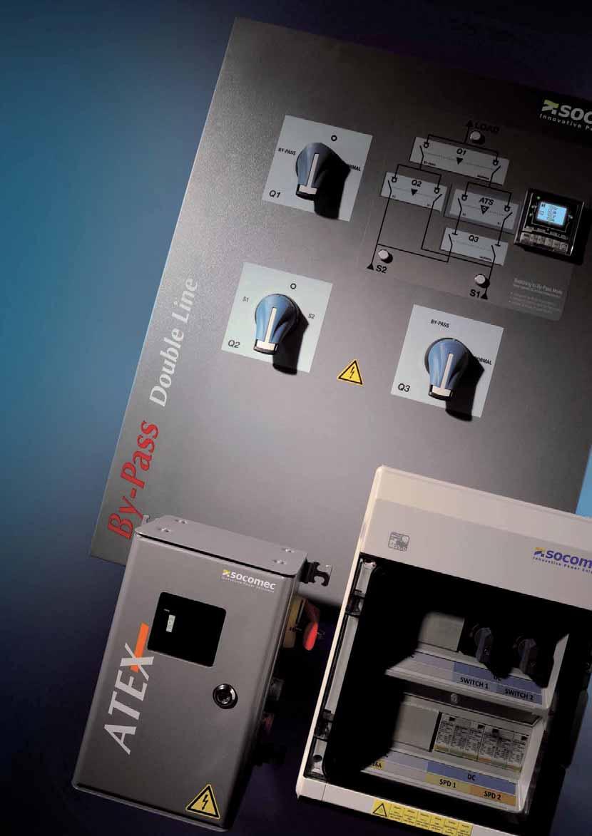
11 Equipped enclosures and cabinets to suit all your applications Equipment enclosures Our switchgear enclosures incorporate loadbreak switches with or without fuses, and have been developed, qualified and certified for industrial electrical distribution and service sector networks. They provide on-load breaking and isolation functions, and assure the removal from power supply service for all types of loads. They can also be used as a general switch for equipment in various applications. SITE 301 A Safety enclosures Safety enclosures are designed to be installed near a motor or a machine to separate them from the power supply. These include manually operated, load-break switches that can be padlocked in the OFF position with a visible and reliable display of the switchgear's open position. During preventive maintenance or inspection work, these enclosures ensure operator safety against the accidental startup of electrical machines. For use in an explosive atmosphere (gas/ dust), use our ATEX model to prevent any explosion during the unit's opening/closing phases, which generate electrical arcs. SITE 558 A Switching enclosures SITE 375 A Switching enclosures ensure the availability of electrical power in critical facilities (high-rises, public buildings, hospitals, IT or telecommunications centres, airports, industrial sites, etc.), and can be operated manually or automatically to switch between a normal power source and a backup source (genset or auxiliary transformer) to cover in the event of failure. (fig. 1) For sites that require a power availability rate close to 100%, our ATyS Bypass solution offers dual redundancy during normal operation, service and maintenance work. With its capacity to resume Normal/Bypass channels, the ATyS Bypass solution allows the continued, seamless and safe use of your systems. In industry, our switches can provide: removal of the load from service by the earthing connection (fig. 2) load redundancy (e.g. between motors) (fig. 3) Fig. 1 Fig. 2 Fig. 3 Catalogue Extract

12 Photovoltaic enclosures Integrated products & solutions The photovoltaic market sets high standards in terms of security and quality. After an experimental decade, we now find ourselves at an industrial stage calling for a high level of professionalism. This comes in the standardisation of components, their implementation and installation rules. The only way to ensure the best delivery, security and lifetime of the system is to bring in the skills of a specialist. Mastering photovoltaic technology has enabled SOCOMEC to demonstrate its capacity to find solutions for optimising electrical systems while taking the environment into account. What you need to know! For more information, please refer to our "Photovoltaic technical specifications" on our website, We can offer you complete solutions compliant with standard IEC Please contact us for more details Catalogue Extract
13 Photovoltaic enclosures Main architectures Centralised inverter systems DC protection AC protection This architecture is primarily for domestic use requiring less than 10 kwp power. Just one fault can jeopardise production. Multi-inverter installations This architecture is designed for high-power industrial systems ranging from a few hundred kw to many MWp. In case of a fault or maintenance, the loss of production is limited to that machine. Multi-inverter systems with individual control With this architecture we can reduce the power of PV inverters, by splitting all the PV generators and inverters over multiple lines. catec-pv_054_b_1_gb PV panels DC protection Conversion AC protection Connection to mains network catec-pv_055_b_1_gb catec-pv_053_b_1_gb PV panels Conversion Connection to mains network Network Multi-inverter systems with centralised control Connecting PV generators in parallel to all the inverters allows a high level of flexibility in terms of maintenance and managing the operating time of the machines. This method also ensures the inverters are used at their optimum power depending on the sunlight. PV panels DC protection Conversion AC protection Connection to mains network Key functions Inverter DC/AC conversion Converting the continuous electric energy produced by photovoltaic panels into alternative electrical energy. Automatic disconnection (loss of insulation, mains power, etc.). DC side, upstream of the inverter Switching and isolation. Short-circuit and overvoltage protection (fusing). Double insulation (class 2). System monitoring. Arc-fault detection. Switch tripping. Photovoltaic generator PV panels. AC side, downstream of the inverter Switching and isolation. Short-circuit and overvoltage protection (fusing). Differential control and protection. Network coupling Metering. Switching and isolation. LV/HV conversion, depending on the installation's power. Catalogue Extract


14 Solutions for medical locations Integrated products & solutions SOCOMEC "Medical IT cabinet" solutions The availability of a reliable electrical power supply is vital to ensure the continuity of care. Our solutions for medical locations guarantee: the continuity of the power supply within medical locations, patient safety with specific power distribution (hospital isolated power system). With this equipment we can meet the requirements of IEC , NFC and Harmonisation Document HD "Medical IT" cabinets guarantee a high-level of availability and high-quality electrical distribution in operating rooms. They provide the following benefits: the continuity and availability of the power supply for critical rooms class 0 (or level 1, no cut-off tolerated), detection of insulation faults, scalability through the implementation of additional outgoing circuits, easy to maintain. The document HD stipulates that the medical IT transformer be installed as close as possible to the medical locations. All our solutions are supplied with standard protection devices. We can offer you complete solutions compliant with standard IEC Please contact us for more details. 14 Catalogue Extract
15 Solutions for medical locations Electrical architecture of the solution The standard NFC requires a medical IT scheme for group 2 locations and at least one transformer for each operating room or each medical site Transformer for medical IT scheme Permanent insulation monitoring + alarm reports SOCOMEC oil-free TRM transformers are LV/ LV transformers that separate the general distribution network from the medical room power supply provided by the IT scheme. As such, they can isolate and compartmentalise the electrical disturbances across the entire installation. The medical IT scheme is required by the installation standards NFC , HD for group 2 locations. The permanent insulation controller HMD 420 is a combined device for monitoring: - the insulation level of the medical IT scheme, - the load current of single-phase transformer for medical IT schemes (up to 50 A), - the temperature of the medical IT transformers. It also integrates an additional signal for detecting insulation faults and it synchronises with fault locators DLD or DLD Outputs Insulation monitor C I> Injector Fault locator Alarm report coff_480_b_1_gb_cat.ai The document HD stipulates that group 2 medical locations be powered by 2 separate sources Automatic transfer switch Static transfer system Switch 1 Switch 2 Insulation monitor C I> ATyS M are automatic transfer switches that provide automatic switching to a main power supply. They have been developed, tested and approved according to criteria defined by the international product standards IEC and IEC Static transfer switches ensure a power supply redundancy between two independent sources while delivering continuous service to critical applications by choosing the best power supply quality. Loads are transferred without interruption. Outputs Injector Fault locator Alarm report coff_481_b_1_gb_cat.ai The installation standard NFC requires that group 2 locations are powered without interruption Uninterruptible Power Supplies MODULYS Uninterruptible Power Supplies (UPSs) (and NETYS RT, depending on the application) ensure continuity of power. Double conversion technology ensures the ultimate protection for loads. The rack design meets all needs to extend power and/or redundancy. Normal M Standby Insulation monitor C I> Injector Alarm report Outputs Fault locator coff_482_b_1_gb_cat.ai Catalogue Extract


 Available at your local distributor")
16 Enclosed load break switches COMO from 20 to 125 A Integrated products & solutions como-enc_001 como-enc_005 The solution for > OEM > Industries > Power distribution 20 A, 3/4 poles, IEC Polycarbonate 25, 32, 40 A, 3/4 poles, IEC Polycarbonate Function 32, 63, 80, 100 A, 3/4/6/8 poles, IEC Polycarbonate COMO are load break switches that will make and break on load and provide isolation for any low voltage electrical circuit. COMO are now available in enclosed version incorporating three, four, six and eight-pole manually operated load break switches. como-enc_008 63, 125 A, 3/4/6/8 poles, IEC Polycarbonate The new enclosed COMO provide protection against contact with live parts as well as environmental factors such as dust, water and other hazards. como-enc_011 Strong points > Compact design > IP 65 > Safety of operations > Wide range Conformity to standards > IEC > EN (please consult us) Available at your local distributor Advantages Compact design The enclosed COMO range offers compact enclosures tailored to your needs. The range starts with the 20 A enclosure with dimensions of only 64x74.5 mm (2.5x2.93 in). IP 65 The IP65 protection degree provides protection against dust and high pressure water jets for any industrial application. Available in IP67 for the enclosed COMO 20 A. Safety of operations Triple locking of the handle in the OFF position to ensure maximum safety for operators during maintenance operations. Wide range The range offers a wide variety of variants depending on the number of poles, rating and enclosure type. 16 Catalogue Extract
 (with yellow/red handle) 3 2115 3301 2115 3401 20 A 0 4 2115 4301 2115 4401 3 2115 3302 2115 3402 25 A 1 4 2115 4302 2115 4402 3 2115 3303 2115 3403 1 4 2115 4303")

 No.")
17 Enclosed load break switches COMO from 20 to 125 A References Reference Reference Rating (A) Enclosure size No. of poles (with grey/blue handle) (with yellow/red handle) A A A A A A A A Accessories Additionnal pole Use Installation of this solid pole converts a 3/4/6/8 pole enclosed COMO into a 3/4/6/8 pole+neutral enclosed load break switch. The 4 th pole can be added without tools on the right or left side of the device. Max 1 additionnal module per device. Solid neutral pole Rating (A) No. of poles Type Reference Unswitched Unswitched Unswitched Unswitched Possible configurations Additional contact Product Additional contact Aux. contact 3/4/6/8P Aux. contact Solid neutral 3/4/6/8P Aux. contact Aux. contact 3/4/6/8P Solid neutral Auxiliary contacts Use Pre-break and signalling of positions 0 and I by NO+NC or 2 NO auxiliary contacts. They can be mounted on the left or right side of the device. It is possible to add up to 2 auxiliary contacts on each product. This is limited to 1 auxiliary contact when a solid neutral pole is used. Rating (A) No. of AC Type of AC Reference 1 2 NO NO + NC como_189_a Catalogue Extract
18 Enclosed load break switches COMO from 20 to 125 A Characteristics Characteristics according to IEC Thermal current at 40 C 20 A 25 A 32 A 40 A 63 A 80 A 100 A 125 A Rated insulation voltage U i (V) Rated impulse withstand voltage U imp (kv) Rated current I n Rated voltage Utilisation category 400 VAC AC-21A VAC AC-22A VAC AC-23A VAC AC-3A VAC AC-21A VAC AC-23A , VAC AC-3A Operational power in AC-23 (kw) (1) 400 VAC VAC Operational power in AC-3 (kw) (1) 400 VAC VAC Fuse protected short-circuit withstand (ka rms prospective) at 400VAC Prospective short-circuit current (ka rms) Associated fuse rating (A) Circuit breaker protected short-circuit withstand with any breaker that ensures tripping in less than 0.3s Rated short-time withstand current 0.3s I cw (ka rms) Short-circuit capacity (without protection) Rated short-time withstand current 1s I cw (ka rms) Connection Minimum Cu cable cross-section (mm²) Maximum Cu cable cross-section (mm²) Tightening torque min/max (Nm) 1/ /3 2.5/3 2.5/3 2.5/3 2.5/3 2.5/3 2.5/3 Mechanical characteristics Durability (number of operating cycle) Operating effort - 3 pole device (Nm) Operating effort - 4 pole device (Nm) Weight of a 3 P enclosure (kg) Weight of a 4 P enclosure (kg) Weight of a 6 P enclosure (kg) Weight of a 8 P enclosure (kg) Catalogue Extract
19 Enclosed load break switches COMO from 20 to 125 A Dimensions Size 0 Size Fix pre-drilled holes M25 (top and bottom) 4 pre-drilled holes M20 (on the side) 4 pre-drilled holes M25 (top and bottom) 4 pre-drilled holes for water escape Size 2 Size Fix coff_506_a.ai ,5 Fix Fix. 239 Ø 6,5 coff_507_a.ai coff_505_a.ai coff_504_a.ai 4 pre-drilled holes M20 (on the side) 4 pre-drilled holes M32/M40 (top and bottom) 2 pre-drilled holes for water escape 4 pre-drilled holes M20 (on the side) 4 pre-drilled holes M50/M63 and 2 pre-drilled holes M20 (top and bottom) 2 pre-drilled holes for water escape Catalogue Extract

 > Robust product > Compact Compliance with standards Advantages Safety Local isolation is a health & safety requirement to allow downstream")
20 Enclosed load break switches SIRCO and SIRCO M from 20 to 1250 A Integrated products & solutions The solution for > Local isolation > Industries > Commercial buildings coff_516_a.psd coff_295_a_1_cat Enclosed LBS 100 A Enclosed LBS 200 A Strong points Function SIRCO enclosures incorporate three pole and neutral or four pole load break switches which make and break on load and provide isolation for any low voltage electrical circuit. The enclosure provides protection against contact with live parts as well as environmental factors such as dust, water and other hazards. > Maintenance safety > Inductive load breaking (AC23) > Robust product > Compact Compliance with standards Advantages Safety Local isolation is a health & safety requirement to allow downstream equipment to be safely worked on. Inductive load breaking (AC23) Even highly inductive loads (AC23) can be switched off while in operation in case of problems. > BS EN > IEC Other products > Customised solutions available on request. > Stainless steel, other paint colours, labelling. General characteristics Enclosure IP54 rated mild steel enclosures 20 to 1250 A. Hinged doors with fastening screws. Paint finish RAL 7035 polyester textured gloss finish. Metric knockouts Top & Bottom (20 to 100 A). Removable gland plates Top & Bottom (160 to 1250 A). Generous cabling space for incoming and outgoing cables. Switch Disconnectable solid neutral link. Fully rated AC23 suitable for distribution & motor loads. Door interlocked pad-lockable handle as standard. Incoming terminals IP20. Options Extension boxes available. Full range of accessories available. 20 Catalogue Extract
21 Enclosed load break switches SIRCO and SIRCO M from 20 to 1250 A References SIRCO in steel enclosure Rating (A) Enclosure size No. of poles Reference P 26E P 26E P 26E P 26E P 26E P 26E P 26E P 26E P 26E P 26E P 26E P 26E P 26E P 26E P 26E P 26E P 26E P 26E P 26E P 26E P 26E P 26E P 26E P 26E Accessories Cable extension boxes Description IP65 rated. Gland plate used from enclosed load break switch Auxiliary contact Enclosure dimensions H x W x D Reference 275 x 320 x 175 XBE x 450 x 275 XBE x 550 x 300 XBE Contact Rating Description Rating (A) type I th (A) Reference Pre-break auxiliary contact NO + 1 NC Pre-break auxiliary contact NO Pre-break auxiliary contact NC Pre-break auxiliary contact NO + 1 NC Pre-break auxiliary contact (1 st ) NO + 1 NC Pre-break auxiliary contact (2 nd ) NO + 1 NC Dimensions H F Ø 25 W Ø 20 Ø 20 Box 1, 2 TOP / BOTTOM Ø 25 J E D G Box 3, 4, 5 TOP / BOTTOM Rating (A) Enclosure size H x W x D E F Extension Box G J x 180 x x 180 x x 180 x x 180 x x 180 x x 180 x x 180 x x 180 x x 270 x x 270 x x 270 x x 270 x x 320 x x 320 x x 450 x x 450 x x 450 x x 450 x x 550 x x 550 x x 550 x x 550 x x 550 x x 550 x Catalogue Extract
22 Enclosed load break switches SIRCO and SIRCO M from 20 to 1250 A Characteristics Characteristics according to IEC (switch tested in free air) SIRCO M SIRCO MV SIRCO VM Thermal current I th (40 C) 20 A 32 A 63A 100 A 160 A 200 A Rated insulation voltage U i (V) Rated impulse withstand voltage U imp (kv) Rated operational currents I e (A) Rated voltage Utilisation category A/B (1) A/B (1) A/B (1) A/B (1) A/B (1) A/B (1) 415 VAC AC-20 A / AC-20 B 20/20 32/32 63/63 100/ / / VAC AC-21 A / AC-21 B 20/20 32/32 63/63 100/ / / VAC AC-22 A / AC-22 B 20/20 32/32 63/63 100/ / / VAC AC-23 A / AC-23 B 20/20 32/32 63/63 100/ / / VAC AC-20 A / AC-20 B 20/20 32/32 63/63 100/ / VAC AC-21 A / AC-21 B 20/20 32/32 63/63 100/ / VAC AC-22 A / AC-22 B 20/20 32/32 63/63 100/ / VAC AC-23 A / AC-23 B 20/20 25/25 63/63 80/80 100/ VAC AC-20 A / AC-20 B 20/20 32/32 63/63 100/ / VAC AC-21 A / AC-21 B 20/20 32/32 63/63 100/ / VAC AC-22 A / AC-22 B 20/20 32/32 40/63 63/80 100/ VAC AC-23 A / AC-23 B 20/20 25/25 40/40 63/63 80/ VDC DC-20 A / DC-20 B 20/20 32/32 63/63 100/ / VDC DC-21 A / DC-21 B 20/20 (3) 32/32 (3) 63/63 (3) 100/100 (3) 160/160 (3) VDC DC-22 A / DC-22 B VDC DC-23 A / DC-23 B VDC DC-20 A / DC-20 B 20/20 32/32 63/63 100/ / VDC DC-21 A / DC-21 B 20/20 (4) 25/25 (4) 40/40 (4) 63/63 (4) 160/160 (4) VDC DC-22 A / DC-22 B VDC DC-23 A / DC-23 B Operational power in AC-23 (kw) 400 VAC without pre-break AC(kW) (5) VAC without pre-break AC(kW) (5) VAC without pre-break AC(kW) (5) Fuse protected short-circuit withstand (ka rms prospective) (6) Prospective short-circuit current (ka rms) Associated fuse rating (A) Circuit breaker protected short-circuit withstand with any circuit breaker that ensures tripping in less than 0.3s Rated short-time withstand current 0.3s. I cw (ka rms) Short-circuit capacity (without protection) Rated short-time withstand current 1s. I cw (ka rms) Rated peak withstand current (ka peak) (6) Connection Minimum Cu cable cross section (mm²) Maximum Cu cable cross section (mm²) Tightening torque min/max (Nm) 2 / / / / / Mechanical characteristics Durability (number of operating cycles) Operating effort - 3 pole device (Nm) Operating effort - 4 pole device (Nm) (1) Category with index A = frequent operation - Category with index B = infrequent operation. (2) One pole per polarity. (3) 2 poles in series for the + and 1 pole for the -. (4) 2 poles in series per polarity. (5) The power value is given for information only, the current values vary from one manufacturer to another. (6) For a rated operational voltage Ue = 415 VAC. 22 Catalogue Extract
23 Enclosed load break switches SIRCO and SIRCO M from 20 to 1250 A Characteristics according to IEC (switch tested in free air) SIRCO Thermal current I th (40 C) 250 A 400 A 630 A 800 A 1000 A 1250 A Rated insulation voltage U i (V) Rated impulse withstand voltage U imp (kv) Rated operational currents I e (A) Rated voltage Utilisation category A/B (1) A/B (1) A/B (1) A/B (1) A/B (1) A/B (1) 415 VAC AC-20 A / AC-20 B 250/ / / / / / VAC AC-21 A / AC-21 B 250/ / / / / / VAC AC-22 A / AC-22 B 250/ / / / / / VAC AC-23 A / AC-23 B 250/ / / / / / VAC AC-20 A / AC-20 B 250/ / / / / / VAC AC-21 A / AC-21 B 250/ / / / / / VAC AC-22 A / AC-22 B 250/ / / / / / VAC AC-23 A / AC-23 B 200/ / / / / / VAC AC-20 A / AC-20 B 250/ / / / / / VAC AC-21 A / AC-21 B 200/ / / / / / VAC AC-22 A / AC-22 B 125/ / / / / / VAC AC-23 A / AC-23 B 100/ / / / / / VDC DC-20 A / DC-20 B 250/ / / / / / VDC DC-21 A / DC-21 B 250/ / / / / / VDC DC-22 A / DC-22 B 250/ / / / / / VDC DC-23 A / DC-23 B 200/ / / / / / VDC DC-20 A / DC-20 B 250/ / / / / / VDC DC-21 A / DC-21 B 200/200 (3) 400/400 (3) 500/500 (3) 800/800 (3) 1000/1000 (4) 1250/1250 (4) 400 VDC DC-22 A / DC-22 B 200/200 (3) 400/400 (3) 500/500 (3) 800/800 (3) 1000/1000 (4) 1250/1250 (4) 400 VDC DC-23 A / DC-23 B 200/200 (4) 400/400 (4) 500/500 (4) 800/800 (4) 1000/1000 (4) 1250/1250 (4) Operational power in AC-23 (kw) 400 VAC without pre-break AC(kW) (5) 132/ / / / / / VAC without pre-break AC(kW) (5) 140/ / / / / / VAC without pre-break AC(kW) (5) 90/ / / / / /220 Fuse protected short-circuit withstand (ka rms prospective) (6) Prospective short-circuit current (ka rms) Associated fuse rating (A) Circuit breaker protected short-circuit withstand with any circuit breaker that ensures tripping in less than 0.3s Rated short-time withstand current 0.3s. I cw (ka rms) Short-circuit capacity (without protection) Rated short-time withstand current 1s. I cw (ka rms) Rated peak withstand current (ka peak) (6) Connection Minimum Cu cable cross section (mm²) x x x 240 Maximum Cu cable cross section (mm²) x x x x 185 Tightening torque min/max (Nm) / / / / 45 Mechanical characteristics Durability (number of operating cycles) Operating effort - 3 pole device (Nm) Operating effort - 4 pole device (Nm) (1) Category with index A = frequent operation - Category with index B = infrequent operation. (2) One pole per polarity. (3) 2 poles in series for the + and 1 pole for the -. (4) 2 poles in series per polarity. (5) The power value is given for information only, the current values vary from one manufacturer to another. (6) For a rated operational voltage Ue = 415 VAC. Catalogue Extract
24 Enclosed fuse switches FUSERBLOC from 20 to 800 A Integrated products & solutions coff_509_a.psd coff_508_a.psd The solution for > Local load protection > Industries > Commercial buildings FUSERBLOC 200 A in steel enclosure FUSERBLOC 200 A in steel enclosure Strong points Function FUSERBLOC enclosures assure on-load making or breaking and provide safety isolation. When combined with fuses, they also protect against overcurrents for any low voltage electrical circuit. For certain constant high duty applications it is recommended to order a higher rated enclosure and de-rate the fuses according to the load. This helps to improve thermal management. > Safe operations > Robust > Inductive load breaking (AC23) Conformity to standards > BS EN > IEC > IEC > IEC Advantages Safety Local isolation is a health & safety requirement to allow downstream equipment to be safely worked on. Fuses provide the ultimate short circuit protection. Inductive load breaking (AC23) Even highly inductive loads (AC23) can be switched off while in operation in case of problems. Available on request > Customised solutions availablle on request. > Stainless steel, other paint colours, labelling. 24 Catalogue Extract
25 Enclosed fuse switches FUSERBLOC from 20 to 800 A General characteristics Enclosure IP54 rated mild steel enclosures 20 to 800 A. Hinged doors with fastening screws. Paint finish RAL 7035 polyester textured gloss finish. Metric knockouts Top & Bottom (20 to 63 A) Removable gland plates Top & Bottom (100 to 800 A). Generous cabling space for incoming and outgoing cables. Supplied with nominally rated fuses. Switch Disconnectable solid neutral link. Fully rated AC23 suitable for distribution & motor loads. Door interlocked pad-lockable handle as standard. Options Extension boxes available. Full range of accessories available. References FUSERBLOC in steel enclosure coff_509_a.psd Rating (A) Enclosure size No. of poles Reference P 38E P 38E P 38E P 38E P 38E P 38E P 38E P 38E P 38E P 38E P 38E P 38E P 38E P 38E P 38E P 38E P 38E P 38E P 38E P 38E Catalogue Extract
26 Enclosed fuse switches FUSERBLOC from 20 to 800 A Accessories Cable extension boxes Description Enclosure dimensions H x W x D Reference IP65 rated. Gland plate utilised from Enclosed Fuse Combination Switch 275 x 320 x 175 XBE x 450 x 275 XBE x 550 x 300 XBE Auxiliary contact Description Rating I th (A) Switch rating Contact type Reference Separate NO and NC direct mounted auxilliary contact blocks for all Enclosed switches 10 1NO All sizes 20 to 800 A 10 1NC Max 4 auxilliaries can be fitted as standard please consult us for additional configurations. Solid Links Description Rating (A) Switch rating (A) Type BS88 Reference / 32 A A2-A To be used in place of BS88 Fuse Links / 160 / 200 A B1-B B / 800 C1-C Outgoing Shrouds Description Switch rating (A) No. of poles Reference IP20 as standard 20 / 32 / IP20 Terminal shrouds 100 / 160 / P IP20 Terminal shrouds 250 / P IP20 Terminal shrouds 630 / P IP20 as standard 20 / 32 / IP20 Terminal shrouds 100 / 160 / P IP20 Terminal shrouds 250 / P IP20 Terminal shrouds 630 / P Cable lug spacers Description Switch rating (A) No. of poles Reference 100 / 160 / P 39Y Set of 3 spacers for multiple large cables 250 / P 39Y Other accessories available Fuses Full range of BS88 available. From 2 to 1250 A. Key interlocking Accessory to enable Key locking with Ronis EL11AP and Castell FS and K Locks Note: Ronis and Castell locks are not included and must be purchased seperately. Standard catalogue components For all other accessories and the full range of Socomec products please consult our Full UK Catalogue and Price List. 26 Catalogue Extract
27 Enclosed fuse switches FUSERBLOC from 20 to 800 A Dimensions W E D F H Ø 25 Ø 20 Ø 20 Ø 25 G coff_518_a_1_gb_cat.ai Box 1, 2 TOP / BOTTOM J Box 3, 4, 5 TOP / BOTTOM Extension box Rating (A) Enclosure size No. of poles H x W x D E F G J P 215 x 180 x P 215 x 180 x P 215 x 180 x P 215 x 180 x P 300 x 270 x P 300 x 270 x P 395 x 320 x P 395 x 320 x P 395 x 320 x P 395 x 320 x P 395 x 320 x P 395 x 320 x P 600 x 450 x P 600 x 450 x P 600 x 450 x P 600 x 450 x P 750 x 550 x P 750 x 550 x P 750 x 550 x P 750 x 550 x Catalogue Extract
28 Enclosed fuse switches FUSERBLOC from 20 to 800 A Characteristics Characteristics according to IEC (switch tested in free air) Thermal current I n (40 C) 20 A 32 A 63 A 100 A CD 160 A BS88 fuse size A1 A1 A2-A3 A4 max Ø31 mm A4 max Ø31 mm Frame size A Rated insulation voltage U i (V) Rated impulse withstand voltage U imp (kv) Rated operational currents I e (A) Rated voltage Utilisation category A/B (1) A/B (1) A/B (1) A/B (1) A/B (1) 400 VAC AC-22 A / AC-22 B 20/20 32/32 63/63 100/ / VAC AC-23 A / AC-23 B 20/20 32/32 63/63 100/ / VAC AC-22 A / AC-22 B 20/20 32/32 63/63 100/100 (2) 160/160 (2) 690 VAC AC-23 A / AC-23 B 20/20 32/32 63/63 100/100 (2) 125/125 (2) 220 VDC DC-20 A / DC-20 B 20/20 32/32 63/63 100/ / VDC DC-21 A / DC-21 B 63/63 100/ / VDC DC-22 A / DC-22 B 63/63 100/ / VDC DC-23 A / DC-23 B 40/40 100/ / VDC DC-20 A / DC-20 B 20/20 32/32 63/63 100/ / VDC DC-21 A / DC-21 B 63/63 (3) 100/100 (3) 160/160 (3) 440 VDC DC-22 A / DC-22 B 63/63 (3) 100/100 (3) 160/160 (3) 440 VDC DC-23 A / DC-23 B 40/40 (3) 100/100 (3) 125/125 (3) Operational power in AC-23 (kw) At 400 VAC without pre-break in AC (1)(5) 9/9 15/15 30/30 51/51 80/80 At 690 VAC without pre-break in AC (1)(5) 15/15 25/25 55/55 90/90 110/110 Reactive power (kvar) At 400 VAC (5) Fuse protected short-circuit withstand BS88/DIN (ka rms prospective) Prospective short-circuit (ka rms) (6) Associated fuse rating (A) (6) Short-circuit capacity Rated peak withstand current (ka peak) (6) 5,5 5,5 10, Fuse selection (maximum fuse size)** SOCOMEC BS88 - Standard max 6A A A A A SOCOMEC BS88 - Motor max 6A1M A1M A3M0080 (4) 6A4M0125 (4) 6A4M 0160 BUSSMANN - Standard max NITD 20 NITD 32 BAO63 CEO100 DEO160 BUSSMANN - Motor max NITD 20M32 NITD 32M63 BAO63M80 (4) CEO100M125 (4) CEO100M160 (4) LAWSON - Standard max NIT 20 NIT 32 TIS63 TCP100 CTFP160 LAWSON - Motor max NIT 20M32 NIT 32M63 TIS63M80 (4) CTFP100M125 (4) CTCP100M160 (4) GE - Standard max NIT 20 NIT 32 TIS63 TCP100 TCP100 GE - Motor max NIT 20M32 NIT 32M63 TIS36M80 (4) OCP100M125 (4) OCP100M160 (4) Connection Minimum Cu cable cross-section (mm2) Maximum Cu cable cross-section (mm2) Maximum busbar width Min. / Max. tightening torque min (Nm) 2/1.6 2/ / / /12.75 Mechanical characteristics Durability (number of operating cycles) Weight of 3 P switch (kg) Weight of 4 P switch (kg) (1) Category with index A = frequent operation - Category with index B = infrequent operation. (2) With terminal shrouds or terminal screen. (3) 4-pole device with 2 pole in series by polarity. (4) Please ensure that the cut off current of the fuse links does not exceed the values given for the fuse switches. (5) The power value is given for information only, the current values vary from one manufacturer to another. (6) For a rated operational voltage Ue = 400 VAC. * For fuse size A4: max diameter 31 mm. ** Please ensure that fuse let through current does not exceed short-circuit capacity of the switch (ka peak). 28 Catalogue Extract
29 Enclosed fuse switches FUSERBLOC from 20 to 800 A Characteristics according to IEC (switch tested in free air) Thermal current I n (40 C) CD 200 A 250 A 315 A 400 A 630 A BS88 fuse size A4 max Ø31 mm B1 - B3 B1 - B3 B1 - B4 C1 - C2 Frame size 13A Rated insulation voltage U i (V) Rated impulse withstand voltage U imp (kv) Rated operational currents I e (A) Rated voltage Utilisation category A/B (1) A/B (1) A/B (1) A/B (1) A/B (1) 400 VAC AC-22 A / AC-22 B 200/ / / / / VAC AC-23 A / AC-23 B 200/ / / / / VAC AC-22 A / AC-22 B 160/160 (2) 250/250 (2) 315/315 (2) 400/400 (2) 500/630 (2) 690 VAC AC-23 A / AC-23 B 125/125 (2) 250/250 (2) 315/315 (2) 315/400 (2) 315/400 (2) 220 VDC DC-20 A / DC-20 B 200/ / / / / VDC DC-21 A / DC-21 B 160/ / / / / VDC DC-22 A / DC-22 B 160/ / / / / VDC DC-23 A / DC-23 B 125/ / / / / VDC DC-20 A / DC-20 B 200/ / / / / VDC DC-21 A / DC-21 B 160/160 (3) 250/250 (3) 315/315 (3) 315/315 (3) 400/630 (3) 440 VDC DC-22 A / DC-22 B 160/160 (3) 250/250 (3) 315/315 (3) 315/315 (3) 400/630 (3) 440 VDC DC-23 A / DC-23 B 125/125 (3) 200/200 (3) 250/315 (3) 250/315 (3) 400/630 (3) Operational power in AC-23 (kw) At 400 VAC without pre-break in AC (1)(5) 80/80 132/ / / /355 At 690 VAC without pre-break in AC (1)(5) 110/ / / / /400 Reactive power (kvar) At 400 VAC (5) Fuse protected short-circuit withstand BS88/DIN (ka rms prospective) Prospective short-circuit (ka rms) (6) Associated fuse rating (A) (6) Short-circuit capacity Rated peak withstand current (ka peak) (6) 20 32, Fuse selection (maximum fuse size)** SOCOMEC BS88 - Standard max 6A B B B C SOCOMEC BS88 - Motor max 6A4M0200 (4) 6B2M0315 (4) 6B3M0400 (4) 6B4M0500 (4) - BUSSMANN - Standard max DEO20 (4) ED250 ED315 ED400 FF630 (4) BUSSMANN - Motor max DEO100M200 (4) DD200M315 (4) ED315M400 (4) ED400M500 (4) - LAWSON - Standard max CTFP200 (4) TKF250 TKF315 TMF400 TTM630 (4) LAWSON - Motor max CTCP100M200 (4) TF200M315 (4) TKF315M400 (4) TMF400M500 (4) - GE - Standard max TCP100 TKF250 TKF315 TMF400 TTM630 (4) GE - Motor max OCP100M160 (4) TF200M315 (4) TKF315M355 (4) TMF400M450 (4) - Connection Minimum Cu cable cross-section (mm2) x150 Maximum Cu cable cross-section (mm2) X300 Maximum busbar width Min. / Max. tightening torque min (Nm) 12.75/ / / / /25.48 Mechanical characteristics Durability (number of operating cycles) Weight of 3 P switch (kg) Weight of 4 P switch (kg) (1) Category with index A = frequent operation - Category with index B = infrequent operation. (2) With terminal shrouds or terminal screen. (3) 4-pole device with 2 pole in series by polarity. (4) Please ensure that the cut off current of the fuse links does not exceed the values given for the fuse switches. (5) The power value is given for information only, the current values vary from one manufacturer to another. (6) For a rated operational voltage Ue = 400 VAC. * For fuse size A4: max diameter 31 mm. ** Please ensure that fuse let through current does not exceed short-circuit capacity of the switch (ka peak). Catalogue Extract

30 Safety enclosures Integrated products & solutions Socomec safety enclosures are designed for installation near a motor or a machine in order to isolate it from the power supply. All the safety enclosures are equipped with load break switches with front or side manual controls which are lockable in the open position, and with visible, reliable indication of the contacts' open position. They make and break under load conditions and provide safety isolation for any low voltage circuit. During maintenance or inspection operations, the safety enclosures guarantee the operator's protection against the accidental startup of electrical machines. For use in explosive atmospheres, (standard) and ATEX gas (to order) enclosures are available to prevent explosions caused by electrical arcs generated when opening or closing the circuits protected by the device. SITE_258_A Which ambient atmosphere? The operating environment is an essential parameter when choosing an enclosure. Our range of enclosures offers you solutions for the most varied of atmospheres, including the most severe. Atmosphere Normal Explosive Gas Dust coff_323_c_gb Standard enclosure, steel or polyester ATEX enclosure Gas zones 1 and 2 ATEX enclosure Dust zones 21 and 22 Environment Steel enclosure Polyester enclosure Stainless steel enclosures (1) ATEX enclosures Chemical aggression Mechanical risks Dust risks Contamination risks Atmospheric corrosion Risk of explosion (1) Made to order. 30 Catalogue Extract


 COFF_243_A_1_X_CAT COFF_042_A_2_CAT COFF_043_A_2_CAT Flush with the viewing window and directly linked")


31 Safety enclosures Safety functions Positive break indication Visible breaking In position 1 In position 0 Clear indication of the open or closed position of the switch via the handle and its easy-to-read marking. Padlocking When working on the machine during the lockout phase, qualified personnel may perform triple handle padlocking in the open position. The ergonomic handle can accommodate up to three locks. Double locking coff_163_a coff_047_a COFF_037_A_2_CAT COFF_038_A_2_CAT COFF_034_A_1_CAT COFF_035_A_2_CAT COFF_036_A_2_CAT In accordance with NF C , an isolating device is considered as having visible breaking if the separation of the contacts is directly visible. All the devices used in the safety enclosures have visible breaking. Mechanical flag indicator (optional) COFF_243_A_1_X_CAT COFF_042_A_2_CAT COFF_043_A_2_CAT Flush with the viewing window and directly linked to the operating mechanism, this gives clear, at-a-glance indication of contact position, providing easier visualisation of the breaking. In accordance with standard , devices located outside a closed electrical service area must be equipped with the means to allow them to be secured in the OFF position (disconnected state). Qualified personnel may use the ergonomic handle to perform triple handle padlocking. It is possible to close the breaking device when the enclosure door is open by using a tool to inhibit the double lock, thus allowing tests to be carried out by qualified staff. Overview of our range For normal atmosphere For explosive atmosphere Polyester Steel Steel coff_435_a coff_280_a COFF_438_A.EPS COFF_439_A.EPS COFF_440_A.EPS Catalogue Extract

32 Safety enclosures Normal atmospheres polyester enclosures from 50 to 1600 A Integrated products & solutions coff_219_a_2_cat The solution for > Steel works > Cement works > Automotive > Mining industries > Food processing > Chemical industry coff_163_a_3_cat Polyester enclosure with front operation handle Function Polyester enclosure with side operation handle Strong points > Safety of operations > Inductive load breaking (AC23) > Robust design > Easy implementation Safety enclosures equipped with SOCOMEC switches provide emergency breaking, breaking for mechanical maintenance and safety isolation in the vicinity of any low voltage final circuit. Conformity to standards Advantages Safety of operations Visible contacts and positive break indication with the possibility to add a mechanical indicator. Double locked door when the switch is in the OFF position. Triple locking of the handle in the OFF position. Inductive load breaking (AC23) Safety enclosures are designed for use with inductive loads and are able to make and break on load (AC23). Robust design Products have been designed for severe industrial conditions with chemical, pollution or atmospheric corrosion risks (Polyester enclosure: good resistance to chemicals, self-extinguishable at 960 C, etc.) > IEC > IEC > IEC > IEC Specific requests > SOCOMEC can offer customised solutions to meet your specific requirements. Please contact your Socomec office for further information. 32 Catalogue Extract
33 Safety enclosures Normal atmospheres polyester enclosures from 50 to 1600 A General characteristics Breaking device All polyester safety enclosures are equipped with SIDER load break switches and visible, reliable indication of the contacts open position. They make and break under load conditions and provide safety isolation for any low voltage circuit. Enclosure Enclosures are made of glass fibre reinforced polyester and are of the following types: COMBIESTER from 50 to 500 A (RAL7035) MINIPOL from 630 to 800 A (RAL7035) Covers on COMBIESTER enclosures are hinged and equipped with a screw locking system. Doors on MINIPOL enclosures can be locked using a 3 mm double bar key. These enclosures have good resistance to chemical agents and are self-extinguishing at 960 C. These enclosures provide a protection degree of IP55. Wall mounting is achieved using 4 fixing lugs, supplied loose. Visible breaking The contacts are visible through: The transparent cover of COMBIESTER enclosures. A door-mounted triplex glass window on MINIPOL enclosures. This enables the operator to confirm the position of the contacts either during a preventative check or before an operation. Double locking This function is achieved through a simple and robust mechanism using an extension shaft. Activation with the door open remains possible by authorised personnel. Operating handle Polyester safety enclosures are available with front or side operation handles. The handle is red and made of an insulating material (emergency breaking). The handle can be locked in the OFF position using three padlocks. Connection Polyester safety enclosures are available in two versions: TB version (top entry and bottom cable exit) BB version (bottom cable entry/exit). Connection is achieved by running cables to the top for 50 A and 80 A ratings. For higher ratings, the top set of terminals are brought down to the bottom of the enclosure with copper bars for easy connection of the incoming cables. Miscellaneous An earthing bar for connection is available in the enclosure. Protection screen for live parts. Catalogue Extract

34 Safety enclosures Normal atmospheres polyester enclosures from 50 to 1600 A References Front operation coff_219_a_2_cat Side operation coff_163_b_1_cat Rating (A) Front operation (1)(2) Top/Bottom connection Bottom/Bottom connection No. of poles Reference Reference P P P P P P P P P P P P P P P P P P P Rating (A) Side operation (1)(2) Top/Bottom connection Bottom/Bottom connection No. of poles Reference Reference 50 3 P P P P P P P P P P P P P P P P P P P P P P P P (1) For the mechanical indicator option, replace the second digit of the enclosure reference number with the letter V. For example: 3V (2) Stainless steel enclosures, specific locking systems, terminal pre-wired/non pre-wired control auxiliary contacts, ventilation and humidity evacuation systems or cable glands are available upon request. Please consult us. Accessories Auxiliary contacts Use For pre-breaking and signalling of positions 0 and I of the load break switch. Mounting On the double locking system. Possibility of factory mounting on enclosure (please provide enclosure reference when ordering). Contact(s) AC Factory fitted AC 1 st NO/NC changeover AC front operation 125 A (1) 2 nd NO/NC changeover AC front operation 125 A 2 NO/NC changeover AC side operation 2 NO/NC changeover AC wired side operation (1) Factory fitted low level auxiliary (1) (1) (1) Please provide the reference number of the enclosure to be equipped. coff_177_a_1_cat coff_178_a_1_cat coff_002_a_1_x_cat coff_003_a_1_x_cat 1 st NO / NC AC for pre-break nd NO / NC AC for pre-break Catalogue Extract
35 Safety enclosures Normal atmospheres polyester enclosures from 50 to 1600 A Key handle interlocking system Use Kit allowing a RONIS EL11AP or Serv Trayvou XOP10 lock to be fitted for a SIDER 50 to 1600 A, with side operation within a steel or polyester enclosure. Locking in position 0 Factory option Type Reference Reference Locking using RONIS EL 11AP lock (not included) (1) Locking using XOP10 lock (not included) Lock RONISEL11AP Serv Trayvou XOP10 lock (1) Please provide the reference number of the enclosure to be equipped. Rated operational currents I e (A) coff_205_c_1_cat Rated voltage Utilisation category 50 A 80 A 125 A 200 A 400 A 500 A 630 A 800 A 1250 A 1600 A 400 VAC AC VAC AC VAC AC VAC AC VAC AC VAC AC Motor power output (kw) 400 VAC without pre-break AC VAC without pre-break AC VAC without pre-break AC VAC without pre-break AC Dimensions Front operation H W Side operation coff_118_d_1_gb_cat B1 Ab Ah D 65 Top/Bottom connection Bottom/Bottom connection Rating (A) No. of poles H x W x D Connection cross-section (mm 2 ) Ah B1 Weight (kg) Ab B1 Weight (kg) 125 3/4 P 360 x 270 x /4 P 360 x 270 x P 360 x 540 x P 360 x 270 x P 540 x 270 x P 360 x 360 x P 540 x 360 x P 360 x 540 x /4 P 720 x 540 x /4 P 720 x 540 x /4 P 800 x 600 x x /4 P 800 x 600 x x /4 P Please consult us 4 x /4 P Please consult us 4 x N H M W 45 coff_119_f_1_gb_cat B1 Ab Ah Z Z1 D Top/Bottom connection Bottom/Bottom connection Rating No. of (A) poles H x W x D Connection Ah B1 Weight Ab B1 Weight cross-section (mm 2 ) (kg) (kg) 50 3/4 P 270 x 180 x P 270 x 360 x /4 P 270 x 180 x P 270 x 360 x /4 P 360 x 270 x P 360 x 540 x P 360 x 270 x P 540 x 270 x P 360 x 360 x P 540 x 360 x P 540 x 540 x /4 P 720 x 540 x /4 P 720 x 540 x /4 P 800 x 600 x x /4 P 800 x 600 x x /4 P Please consult us 4 x /4 P Please consult us 4 x Catalogue Extract

 Advantages Operator safety Protects operators against accidental startup of machines.")
36 Safety enclosures Normal atmospheres steel enclosure from 50 to 1600 A Integrated products & solutions The solution for > Iron and steel industry > Cement plants > Paper mills > Sawmills > Hydraulic power packs > Automotive > Mining coff_436_a coff_434_a Strong points Function Safety enclosures equipped with SOCOMEC switches provide emergency breaking, breaking for mechanical maintenance and safety isolation in the vicinity of any low voltage final circuit. > Operator safety > Quick and easy implementation > Operating continuity > Inductive load breaking (AC23) Advantages Operator safety Protects operators against accidental startup of machines. Ease of operation without risk of error for unqualified operators. Maximum security for all types of simple mechanical and electrical maintenance operations. Quick and easy implementation The space available within the enclosure and the dimensions of the closing plates facilitate connection. Operating continuity Local disconnection: only the targeted machine is switched off, the rest of the installation can continue operating. Reduced costs related to production downtime. Inductive load breaking (AC23) Safety enclosures are designed for use with inductive loads and are able to make and break on load (AC23). Compliance with standards > IEC > IEC > IEC > IEC Specific requirements > SOCOMEC can offer you customised solutons to meet your specific requirements. Contact your Socomec office for further information. Durability The product is designed for harsh industrial environments with mechanical risks or nonexplosive dust risks. 36 Catalogue Extract
37 Safety enclosures Normal atmospheres steel enclosure from 50 to 1600 A General characteristics Enclosure The robustness of the safety enclosure is ensured by its 2 mm thick sheet steel construction. Corrosion protection is provided by a 70 μm thick polyester powder coating (RAL A, RAL 7032 and 9001 for other sizes). The door is hinge-mounted (120 opening) and is secured with a key lock (8 mm square key). The enclosure has an IP65 degree of protection for sizes 160 A and IP55 for other sizes. Switching device Steel safety enclosures are equipped with visible break SOCOMEC load break switches. They make and break under load and provide safety isolation for any low voltage electric circuit. Separation of the contacts is visible through the triplex window, located on the enclosure door, providing guaranteed isolation to the operator. A mechanical indicator, linked directly to the operation of the contacts, is also provided to give clear position indication. Operating handle The safety enclosure is equipped with an unpainted metal operating handle which is used for both normal and emergency cut-off operations. The handle can be locked with up to 3 padlocks with a diameter of between 4 and 8 mm. As an alternative to the standard metallic handle, a red plastic handle with a metal padlocking lever ( 160 A), or a red metallic handle, can be factory fitted on request. coff_435_a Double locking Double locking prevents the opening of the enclosure door with the switch in its closed position and the closing of the switch when the door is open; with the use of a tool authorised personnel can bypass this system when the door is open for maintenance purposes. The locking system comprises a single guard moulded from zamak (aluminium alloy) with a simple and robust mechanism driven directly by the handle s operating shaft. coff_037_a_2_cat Auxiliary control A removable plate, located below the enclosure s operating handle, is supplied for the installation of auxiliary controls. Several wiring combinations are available as pre-installed or customer-fit options for enclosures 160A; for ratings 200A please contact us. coff_038_a_2_cat Connections Two removable (top and bottom) gland plates facilitate cable entry and connections. Cables connect directly onto switch power terminals for enclosures 160A; for 200A incoming cables connect to descending copper bars. Miscellaneous A reversible grounding point enables the termination of earth connections inside and/or outside of the enclosure. All active parts are covered to avoid direct contact. Catalogue Extract
 400 V 690 V No.")
 For top/bottom connection please contact us. (2) For front operation please contact us. (3) Without pre-break option.")
38 Safety enclosures Normal atmospheres steel enclosure from 50 to 1600 A References Safety enclosure with bottom/bottom connection (1), side operation (2) coff_435_a Motor power output (kw) (3) Bottom/Bottom Rating (A) 400 V 690 V No. of poles Reference 3 P A 25-4 P P P A P P P A P P 3V P A P P 200 A P 6 P 3 P 400 A P Accessories (1) For top/bottom connection please contact us. (2) For front operation please contact us. (3) Without pre-break option. Terminal connection kit for 125 and 160 A enclosures 500 A A A A A Use Power terminal connection kit for 125 and 160 A safety enclosures. Allows you to connect up to 2 x 35 mm² cables or 1 x 70 mm² cable per pole. Supplied with terminal separation screens and cables for connection to the switch (for onsite installation). 3 P 4 P 3 P 4 P 3 P 4 P 3 P 4 P 3 P 4 P Consult us Customer fit Factory fitted (1) Designation No. poles Reference Reference Enclosure terminal block 3 P Enclosure terminal block 4 P Contact us Contact us (1) Specify the reference of the enclosure to be fitted. acces_319_a_1_cat 38 Catalogue Extract
.")
39 Safety enclosures Normal atmospheres steel enclosure from 50 to 1600 A Accessories (continued) Auxiliary contacts Use For pre-breaking and signalling of positions 0 and I of the load break switch. Mounting - On the double-locking system. - Possibility of factory mounting within the enclosure (please provide enclosure reference when ordering). coff_177_a_1_cat coff_178_a_1_cat Customer fit (1) Factory fitted (1) Description Rating (A) Reference Reference 2 AC for pre-break and signalling O and I AC low level for pre-break and signalling O and I AC for pre-break and signalling O and I, wired AC low level for pre-break and signalling O and I, wired AC for pre-break and signalling O and I, wired (1) Mounting not compatible with a command and control interface. coff_002_a_1_x_cat 1 st NO/NC AC for pre-break nd NO/NC AC for pre-break coff_003_a_1_x_cat Auxiliary control interface from 50 to 160 A Use For machine control. Mounting - Pushbuttons are wired to terminal block, with 2 onsite connection points. 2 NO/NC auxiliary contacts for pre-break are provided with one utilised in all control options; the 2 nd contact is not pre-wired and is available for use. - The removable interface plate is mounted on the right side of the enclosure below the operating handle. - Factory installation or customer fit options are available. coff_469_a_1_cat Control diagrams (1) Auxiliary control (2) Button allocation Customer fit (3) Factory fitted (3)(4) Start/Stop coff_470_a_1_cat 2 pushbuttons, 22 mm Ø (1 green/1 red): Identification labels Start and Stop Start/Stop and Local/Remote 2 pushbuttons, 22 mm Ø (1 green/1 red): Identification labels Start and Stop 1 selector with 2 positions: Identification label Local-Remote coff_473_a_1_cat Forward/Reverse 3 pushbuttons, 22 mm Ø (2 green/1 red): Identification labels Start, Stop and Reverse coff_472_a_1_cat Forward/Reverse and Local/Remote 3 pushbuttons, 22 mm Ø (2 green/1 red): Identification labels Start, Stop and Reverse 1 selector with 2 positions: Identification label Local-Remote coff_471_a_1_cat (5) (5) (1) See Command diagrams page 41. (2) Labels are identified in English and French languages. (3) Mounting not compatible with an auxiliary. (4) Specify the reference of the enclosure to be fitted. (5) The mounting of a latch locking mechanism is not compatible with this control/command interface with 50 and 80 A ratings. Catalogue Extract


 Specify the reference of the enclosure to be fitted.")
 Customer fit (1) Factory fitted (1)(2) Rating (A) Reference Reference 50")
40 Safety enclosures Normal atmospheres steel enclosure from 50 to 1600 A Accessories (continued) Traffolyte labels Use Personalise your enclosure. Information to be provided at time of order when factory fit option is requested. Examples of label types Customer fit Factory fitted (1) Set of 10 embossed labels, size 80 x 30 mm with black lettering on a white background. Text according to your requirements. Mounted with plastic rivets. Contact us Contact us Pushbutton label, white lettering on a red background Contact us Contact us Pushbutton label, black lettering on a white background Contact us Contact us Pushbutton label, white lettering on a black background Contact us Contact us (1) Specify the reference of the enclosure to be fitted. coff_215_a Key handle interlocking system Use When enabled, the lock prevents handle operation. Type of lock Reference Ronis EL11AP Serv Trayvou NXOP Assembly kit for lock EL11AP (lock not included) Customer fit (1) Factory fitted (1)(2) Rating (A) Reference Reference coff_205_c_1_cat Assembly kit for lock NXOP10 (lock not included) Customer fit (1) Factory fitted (1)(2) Rating (A) Reference Reference (1) Mounting not compatible with a control/command interface. Please contact us for more details. (2) Specify the reference of the enclosure to be fitted. Post mounting Use For mounting the safety enclosure to a round or square post. Rating (A) Reference > 160 Contact us coff_463_a_1_cat Enclosure canopy Use To protect your enclosure against extreme weather. Rating (A) Reference > 160 A Contact us coff_464_a_1_cat 40 Catalogue Extract
41 Safety enclosures Normal atmospheres steel enclosure from 50 to 1600 A Operating handle Use For switch operation. Factory assembly only. Rating (A) Type of handle Reference (1) S type handle, red with metal padlocking lever Red steel handle Red steel handle Red steel handle coff_181_a_1_cat acces_436_a_1_cat (1) Specify the reference of the enclosure to be fitted. Control diagrams Start/Stop -Q AC 11 -X S1 -S2 Stop Start coff_465_b_1_gb_cat.ai Start/Stop and Local/Remote -Q1 AC X S1 -S3 Stop Local Remote 7 8 -S2 Start coff_466_b_1_gb_cat.ai Forward/Reverse -Q AC 11 -X S1 Stop S2 13 -S4 Start 1 Reverse coff_467_b_1_gb_cat.ai Forward/Reverse and Local/Remote -Q AC 11 -X S1 Stop S3 -S2 Local Remote Start S4 Reverse coff_468_b_1_gb_cat.ai Catalogue Extract
42 Safety enclosures Normal atmospheres steel enclosure from 50 to 1600 A Characteristics Characteristics according to IEC Rating (A) 50 A 80 A 125 A 160 A 200 A 400 A 500 A 630 A 800 A 1250 A 1600 A Rated operating current I e (A) Rated voltage Utilisation category (A) (A) (A) (A) (A) (A) (A) (A) (A) (A) (A) 400 VAC AC-21A VAC AC-22A VAC AC-23A VAC AC-21A VAC AC-22A VAC AC-23A Motor power output (kw) At 400 VAC without pre-break AC At 690 VAC without pre-break AC At 400 VAC with pre-break AC At 690 VAC with pre-break AC Characteristics according to IEC Rating (A) 50 A 80 A 125 A 160 A 200 A 400 A 500 A 630 A 800 A 1250 A 1600 A Operating current max, I e (A) 400V Operating current max, I e (A) 690V Mechanical specifications Connection Minimum copper cable cross-section (mm²) x x Maximum copper cable cross-section (mm²) x x x x 240 Min./max. tightening torque (Nm) 2 2 4/4.4 4/ /13 20/26 20/26 20/26 20/26 20/26 40/45 42 Catalogue Extract
43 Safety enclosures Normal atmospheres steel enclosure from 50 to 1600 A Dimensions 50 to 1600 A coff_117_e_1_gb_cat H H1 B1 Ab L1 W 80 D Rating (A) No. poles H x W x D H1 Mounting L1 Connection Ab B1 Weight (kg) 3 P 310 x 215 x P 310 x 215 x P 300 x 400 x P 310 x 215 x P 310 x 215 x P 300 x 400 x P 400 x 275 x P 400 x 300 x P 400 x 400 x P 400 x 275 x P 400 x 300 x P 400 x 300 x P 500 x 400 x P 600 x 500 x P 700 x 400 x P 700 x 400 x P 700 x 400 x P 700 x 400 x P 900 x 500 x P 900 x 500 x P 900 x 500 x P 900 x 500 x P 1200 x 600 x P 1200 x 700 x P 1200 x 600 x P 1200 x 700 x Closing plate Rating (A) A B C A A coff_462_a_1_gb_cat C B Useable area The useable area can be drilled for gland installation. Catalogue Extract
 > Robust design > Protection degree IP65 Function SOCOMEC ATEX enclosures incorporate three or four pole manually operated SIDER")

44 Safety enclosures Explosive atmosphere (ATEX) steel enclosures from 50 to 630 A Integrated products & solutions The solution for > Steel works > Cement works > Mining industries coff_280_b_1_cat Strong points > Safety of operations > Inductive load breaking (AC23) > Robust design > Protection degree IP65 Function SOCOMEC ATEX enclosures incorporate three or four pole manually operated SIDER (ND) load break switches which make and break on load, providing emergency breaking and maintenance isolation for any low voltage electrical circuit which is in an area where there is a risk of explosion due to dust. Advantages Safety of operations Visible contacts and positive break indication through the operating handle and a factory fitted mechanical flag indicator, provide guaranteed position indication of the contacts. Double locked door when switch is in the OFF position. Triple locking of the handle in the open position. Inductive load breaking (AC23) ATEX enclosures are designed for use with inductive loads and are able to make and break on load (AC23). Steel enclosures from 50 to 630 A Robust design Product has been specifically designed for industrial environments with the risk of explosion due to dust (galvanised steel, thickness 2 mm, triplex glass, S type handle with metal padlocking lever ) Protection degree IP65 Protection degree of ATEX enclosures is IP65. Conformity to standards > Directive 94/9/CE > IEC > IEC > IEC > IEC > NF C Other regulations > Decree : Machine safety > Decree n from : protection of workers > Decree n from > Decree : machine compliance Specific requests > SOCOMEC can offer customised solutions to meet your specific requirements. Please contact your Socomec office for further information. 44 Catalogue Extract
45 Safety enclosures Explosive atmosphere (ATEX) steel enclosures from 50 to 630 A General characteristics Breaking device All safety enclosures are equipped with load break switches that provide visible, reliable indication of the contacts open position. SIDER for 50 A, 80 A and 630 A ratings SIDER ND 80 A (6 P) to 400 A ratings They make and break under load conditions and provide safety isolation for any low voltage circuit. They are factory fitted with a mechanical flag indicator (SIDER) which provides guaranteed position indication of the contacts. Enclosure Enclosures are made of a 2 mm thick galvanised steel. They are welded and deburred. The anti-corrosion protection is achieved using an epoxy polyester powder which polymerises in the oven at 180. Paint coating is 60 μm minimum and colour is metallic gray. The chrome-plated zamak door is assembled on an invisible hinge and is locked using an 8 mm square key. Wall mounting is achieved using 4 fixing lugs (factory mounted). Visible breaking The contacts are visible through a triplex window, located on the enclosure door. This enables the operator to confirm the position of the contacts either during a preventative check or before an operation. Double locking This function is achieved through a simple and robust mechanism using an extension shaft. Activation with the door open remains possible by authorised personnel. Operating handle ATEX enclosures are provided with a red S type operation handle. It is made of an insulating material and includes a metal padlocking lever. The handle can be locked in the OFF position using three padlocks. Connection Steel safety enclosures are available with bottom cable entry and exit. Enclosures are fitted with a top roof and bottom closing plate. Connection is achieved by running cables to the top terminal for 50 and 80 A ratings. For higher ratings, the top set of terminals are brought down to the bottom of the enclosure with copper bars for easy connection of the incoming cables. Miscellaneous Two earthing bars for connection are available in the enclosure. Protection screen for live parts. Catalogue Extract
46 Safety enclosures Explosive atmosphere (ATEX) steel enclosures from 50 to 630 A References coff_280_b_1_cat Rating (A) No. of poles Bottom/Bottom connection Reference 50 3 P 3V P 3V P 3V P 3V P 3V P 3V P 3V P 3V P 3V P 3V P 3V P 3V P 3V P 3V Accessories ATEX cable gland Black polyamide Diameter Min. cable diameter Max. cable diameter Cable gland Reference Locknut Reference coff_283_a_1_cat Brass Max. cable diameter Cable gland Locknut Diameter Min. cable diameter Reference Reference coff_329_a_1_cat 46 Catalogue Extract
47 Safety enclosures Explosive atmosphere (ATEX) steel enclosures from 50 to 630 A Characteristics Rating (A) 50 A 80 A 80 A 125 A 160 A 200 A 400 A 630 A Rated operational currents I e (A) Rated voltage Utilisation category 3/4 P 3/4 P 6 P 3/4 P 6 P 3/4 P 3/4 P 3/4 P 415 VAC AC-21 A/B 50/50 63/63 -/80 125/125 -/ /200 /315 -/ VAC AC-22 A/B 50/50 63/63 -/80 125/125 -/ /200 /315 -/ VAC AC-23 A/B 25/25 40/40 -/80 125/125 -/ /200 /315 -/- Motor power output (kw) 400/500 VAC without pre-break AC 11/- 18.5/15 40/- 60/- 80/- 100/- 160/- 270/- 400/500 VAC with pre-break AC 25/- 30/25 40/- 60/- 80/- 100/- 160/- -/- Dimensions H coff_289_c_1_gb_cat W (1) (1) A: 45 mm 630 A: 61 mm B1 Ab D Bottom/Bottom Cross-section connection Rating (A) No. of poles H x W x D (mm 2 ) Ab B1 Weight (kg) 50 3/4 P 350 x 225 x /4 P 350 x 225 x P 500 x 425 x /4 P 500 x 425 x P 500 x 425 x /4 P 500 x 425 x /4 P 700 x 500 x x /4 P 700 x 500 x x Catalogue Extract
.")

. RTSE (Remote Transfer Switching Equipment). ATSE (Automatic Transfer Switching Equipment).")
48 Enclosed transfer switches Integrated products & solutions The switching market is a highly demanding market in terms of safety and quality. Changeover switches are essential devices used to guarantee a continuous power supply for critical installations (high-rise buildings, healthcare buildings, data centres, banks, etc.). SOCOMEC's expertise in switching technology enables it to optimise your electrical installations, thereby guaranteeing continuous electrical power. To ensure optimal functional safety, all SOCOMEC enclosed changeover switches are compliant with standards IEC / IEC and standard IEC governing switchgear. From the small 25 A manual changeover unit to the 3200 A ATyS bypass unit, SOCOMEC offers a complete range covering all your needs. Glossary for IEC Terms: MTSE (Manual Transfer Switching Equipment). RTSE (Remote Transfer Switching Equipment). ATSE (Automatic Transfer Switching Equipment). Changeover switches in the SOCOMEC range are type PC. The range is designed to establish and support short circuits. Typical applications Source transfer Earthing Solution enabling manual or automatic switching between two sources, either transformer or generator (fig. 1). Earthing of equipment such as motors or electrical lines whilst isolating them from their power supply in a fail-safe way (fig. 2). SITE 493 A Fig. 1 Fig.2 SITE 499 A Load switching Switching of the power supply from one load to another in order to guarantee redundancy and balancing of the operating time for the two loads (fig. 3). Inversion of phases on motors Inversion of the succession of phases supplying a motor in order to modify the direction of rotation (fig. 4). SITE 483 A Fig. 3 Fig.4 48 Catalogue Extract
.")

49 Enclosed transfer switches Overview of our range Manual operation Motorised and automatic switching COFF_293_B_1_CAT Solution enabling switching, source inversion and breaking in complete safety on low voltage power circuits. p. 50 Motorised solution: Source changeover switch controlled remotely by an external controller using pulse logic or maintained contact (contactor). Automatic solution: Autonomous source changeover switch. p. 56 COFF_339_A_2_CAT COFF_305_B_1_CAT ATyS Bypass automatic switching TABLO_036_A_1_CAT Automatic switching solution enabling switching between two independent sources. Solution enabling the automatic changeover switch to be isolated and a bypass to be created (inspection operations) in complete safety and in a transparent way in terms of the load (no power disconnection). p. 62 Catalogue Extract

50 Enclosed transfer switches Manual operation MTSE * - Polyester enclosures from 25 to 630 A Integrated products & solutions The solution for > Safe supply of medium critical loads Function coff_339_a_1_cat COMO C in polyester enclosure These manually operated changeover switches are mainly used to provide the following functions: Changeover/source inversion. Switching. Earthing. Changeover. Safety isolation. coff_299_a_1_cat Advantages SIRCOVER in polyester enclosure The COMO C and SIRCOVER ranges are multipole changeover switches with positive break indication for safe operations. The SIRCOVER range is designed for use in AC22 and AC23 utilisation categories. Strong points > Safe operations > Utilisation categories AC22 and AC23 > Robust > Compact design Conformity to standards > IEC > IEC > IEC > EN COMO C range General characteristics References coff_339_a_2_cat Dimensions como_078_b_x_cat B A Adapted to environments subject to chemical, dust, contamination and atmospheric corrosion risks. Operating handle: Red/yellow handle Protection degree: IP65. Colour: RAL Material: glass fibre reinforced polyester. Product supplied as a kit, to be assembled. Locking system: screw Rating (A) No. of poles (1) Derated to 70 A for 4 pole. Switching type A B Reference 25 3 P I - II C P I - II C P I II C P I II C P I - I+II - II C P I - I+II - II C P I - II C P I - II C P I II C P I II C P I - I+II - II C P I - I+II - II C P I - II C P I - II C P I II C P I II C P I - I+II - II C P I - I+II - II C P I - II C P I - II C08 (1) 80 3 P I II C P I II C08 (1) 80 3 P I - I+II - II C P I - I+II - II C08 (1) * MTSE: Manual Transfer Switching Equipment 50 Catalogue Extract
51 Enclosed transfer switches Manual operation MTSE - Polyester enclosures from 25 to 630 A SIRCOVER range References coff_299_a_1_cat Rating (A) No. of poles Top/Bottom connection I II Reference P P P P P P P P P P General characteristics Adapted to environments subject to chemical, dust, contamination and atmospheric corrosion risks. Operating handle: S type black handle, padlockable in position 0. Protection degree: IP55 / IK 10. Colour: RAL 7030 (range < 400 A), RAL 9002 (range 400 A). Closing plate: N/A. Material: glass fibre reinforced polyester. Coating: N/A. Wall mounting: 4 mounting brackets supplied (not mounted). Locking system: square key (ratings < 400 A), 3 mm double bar key (ratings 400 A), key supplied. Miscellaneous: good resistance to creepage currents, high resistance to chemicals, self-extinguishable at 960 C, 2 bolted earth connection points. coff_121_h_1_gb_cat Dimensions N H (1) A: 45 mm Rating (A) No. of poles M W H x W x D Max. connection cross-section (mm 2 ) B1 Ah M Z N D (1) Z Ah Connection Top/Bottom B1 Weight (kg) P 540 x 270 x P 540 x 360 x P 540 x 270 x P 540 x 360 x P 540 x 360 x P 540 x 360 x P 800 x 600 x P 800 x 600 x P 800 x 600 x x P 800 x 600 x x Catalogue Extract

52 Enclosed transfer switches Manual operation MTSE * and Bypass - Steel enclosures from 63 to 3200 A Integrated products & solutions The solution for > Safe supply of medium critical loads > Secure electrical supply to non-critical loads coff_293_b_1_cat Function SIRCO VM1 changeover switches in steel enclosure These manually operated changeover switches are mainly used to provide the following functions: Changeover/source inversion. Generator connection points. Earthing. Duty/standby selection. Safety isolation coff_298_b_1_cat Advantages SIRCOVER in steel enclosure The SIRCO VM1 and SIRCOVER ranges are multipole changeover switches with positive break indication for safe operations. The SIRCO VM1 also enables visible double breaking. The SIRCOVER range is designed for use in AC22 and AC23 utilisation categories. The SIRCO VM1 and SIRCOVER ranges are available in I, 0, II / I, I+II, II / Bypass versions (SIRCOVER only). Strong points > Visible double breaking (SIRCO VM1) > On load operation (AC22/AC23) - SIRCOVER > Safety of operations > Robust product > Compact design Conformity to standards > IEC > IEC > IEC > EN Specific requests > SOCOMEC can provide a wide range of specific solutions. Please consult us. What you need to know SIRCOVER Bypass products are a combination of three interlocked switches enabling the use with poles or poles. They insulate by providing simultaneous safety isolation top and bottom and bypassing loads or low voltage circuits mainly during maintenance operations atys_570_a_1_x_cat * MTSE: Manual Transfer Switching Equipment 52 Catalogue Extract

. Miscellaneous: 2 earth connection points, double door locking. References Top/Bottom connection Rating (A) No.")
53 Enclosed transfer switches Manual operation MTSE and Bypass - Steel enclosures from 63 to 3200 A coff_293_b_1_cat SIRCO VM1 changeover switches in steel enclosure Front operation General characteristics Adapted to mechanical risk and dust hazard. Operating handle: S-type black handle padlockable. Protection degree: IP54 / IK 09. Colour: epoxy polyester powder RAL Cable gland plate: top and bottom. Material: XC steel, thickness 1.5 mm. Coating: epoxy polyester powder. Wall mounting: 4 mounting brackets supplied (not mounted). Door: solid with hinges. Locking system: 3 mm double-bar key (key supplied). Miscellaneous: 2 earth connection points, double door locking. References Top/Bottom connection Rating (A) No. of poles Reference 63 3 P P P P P P Dimensions coff_317_a_1_x_cat Rating (A) Max. connection section (mm 2 ) Weight (kg) 3 x 63 / 4 x x 80 / 4 x x 100 / 4 x IP20 bridging bar Use For creating a common connection between switches I & II, on the top or bottom side of the SIRCO VM1, to enable, for example, the load to be fed from either incoming source (I or II). Rating (A) No. of poles Reference P P The bridging bar does not reduce the connection capacity of the cage clamp terminals. comut_005_a_1_cat NO/NC auxiliary contact Use Pre-breaking and signalling of positions I and II: 1 NO/NC auxiliary contact for each position. Characteristics Snaps on and is secured by a screw. Connector block with a maximum capacity of up to 2 x 1.5 mm 2 per terminal. Rating (A) Switching type Contact(s) Reference I II (1) (1) Not available for overlapping contact switch (I-I+II-II). Catalogue Extract
54 Enclosed transfer switches Manual operation MTSE and Bypass - Steel enclosures from 63 to 3200 A SIRCOVER & SIRCOVER Bypass in steel enclosure Front operation References coff_298_b_2_cat SIRCOVER Rating (A) No. of poles I II Reference (1) Top/Bottom connection I - I+II - II Reference (2) P P P P P P P P P P P P P P P P P P (1) Provided without bridging bars. (2) Povided with bridging bars. SIRCOVER Bypass Rating (A) No. of poles Top/Bottom connection I II Reference (1) P P P P P P P P P P P P P P P P P P (1) Povided with bridging bars. General characteristics SIRCOVER SIRCOVER Adapted to mechanical risk and dust hazard. Operating handle: S-type black handle padlockable in position 0. Protection degree: IP54 / IK 09. Colour: RAL 7035 (range < 630 A), RAL 9001 for casing and door, other RAL Cable gland plate: top and bottom. Material: XC steel, thickness 1.5 mm. Coating: epoxy polyester powder (range < 630 A), polyester powder (range 630 A). Wall mounting: 4 mounting brackets supplied (not mounted). Door: solid with hinges. Locking system: 3 mm double bar key (ratings < 630 A), 8 mm square key (ratings 630 A), key supplied. Miscellaneous: 2 earth connection points, double door locking. SIRCOVER Bypass Adapted to mechanical risk and dust hazard. Operating handle: S-type black handle padlockable in position 0. Protection degree: IP54 / IK 09. Colour: casing and door RAL 9001, locking plates RAL 7035 Cable gland plate: top and bottom. Material: XC steel, 2 mm thick, EZ electrogalvanised steel 25/25. Coating: polyester powder. Wall mounting: 4 mounting brackets supplied (not mounted). Door: solid with hinges. Locking system: 3 mm double bar key (ratings < 630 A), 8 mm square key (ratings 630 A), key supplied. Miscellaneous: 2 earth connection points, double door locking. Dimensions SIRCOVER coff_318_a_1_x_cat H N M L (1) A: 58 mm A : 74 mm. Ah B1 Z P (1) Rating (A) No. of poles H x W x D Max. connection cross-section (mm 2 ) M N Z Top/Bottom connection Ah B1 Weight (kg) 125 3/4 P 500 x 400 x /4 P 500 x 400 x /4 P 500 x 400 x /4 P 800 x 600 x /4 P 800 x 600 x /4 P 800 x 600 x x /4 P 1200 x 700 x x /4 P 1200 x 700 x x /4 P 1200 x 700 x x Catalogue Extract
55 Enclosed transfer switches Manual operation MTSE and Bypass - Steel enclosures from 63 to 3200 A Dimensions SIRCOVER Bypass coff_276_c_1_x_cat H N M L (1) A: 58 mm A: 74 mm A : 120 mm Ah B1 Z P (1) Rating (A) No. of poles H x W x D Max. connection cross-section (mm 2 ) M N Z Top/Bottom connection Ah B1 Weight (kg) / 4+8 P 500 x 400 x (1) / 4+8 P 500 x 400 x (1) / 4+8 P 800 x 600 x (1) / 4+8 P 800 x 600 x (1) / 4+8 P 800 x 600 x (1) / 4+8 P 800 x 600 x x (1) 800 3/4 P 1200 x 700 x x /4 P 1200 x 700 x x /4 P 1200 x 700 x x (1) Please consult us. SIRCOVER & SIRCOVER Bypass accessories Bridging bars Use For creating a common connection between switches I & II, on the top or bottom side of the SIRCOVER, to enable, for example, the load to be fed from either incoming source (I or II). Rating (A) Frame size No. of poles Diameter Reference B3 1 P 20 x B4 1 P 25 x B4 1 P 32 x B5 1 P 32 x B5 1 P 50 x B6 1 P 50 x B6 1 P 60 x B7 1 P 90 x For SIRCOVER Bypass, two sets of bridging bars are required (3/6 pole or 4/8 pole switch). svr_124_a_1_cat acces_205_a_2_cat acces_041_a_1_cat SIRCOVER I-0-II and SIRCOVER I-I+II-II acces_208_a_2_cat svr_068_a_1_x_cat SIRCOVER Bypass Auxiliary contact for SIRCOVER Use Pre-breaking and signalling of positions I and II: 1 to 2 NO/NC auxiliary contacts in each position. Low level AC: consult us. Characteristics Rating (A) Frame size Nominal current (A) 250 VAC AC-13 Connection to the control circuit By 6.35 mm fast-on terminal. Electrical characteristics 30,000 operations. Operating current I e (A) 400 VAC AC VDC DC-13 NO/NC changeover contact Rating (A) Frame size Contact(s) Reference B3 B7 1 st / 2 nd B8 1 st / 2 nd included 48 VDC DC B3... B acces_065_a_1_cat svr_058_a_1_cat Catalogue Extract

56 Enclosed transfer switches Motorised operation ATSE * - Automatic equipment from 40 to 3200 A Integrated products & solutions The solution for > High-rise buildings > Data centers > Energy generation > Healthcare buildings > Banks and insurance companies > Transport (airports, tunnels, etc.) coff_366_b_1_cat coff_305_b_1_cat ATyS g M and ATyS p M three-phase in steel enclosure ATyS p three-phase in steel enclosure Function ATSE switching enclosures are autonomous solutions which monitor the incoming supplies and automatically transfer to ensure power availability for critical applications. From 40 to 160 A, enclosures are equipped with ATyS g M (2 P/4 P - simplified control system) or ATyS p M (4 P - advanced control system) in modular format for optimised integration. Advantages Dedicated solution ATSE solutions have been designed and tested with ease-of-use in mind. From 125 to 3200 A, enclosures are equipped with ATyS p (4 P - advanced control system) with back-to-back switch configuration, providing a more compact device and enabling easier connection. Multiple configurations The ATSE range is available in polycarbonate or steel enclosures. Strong points > Dedicated solution > Multiple configurations > Robust product > Easy integration Compliance with standards > IEC > IEC ,-1 > IEC > BS * ATSE: Automatic Transfer Switching Equipment 56 Catalogue Extract
57 Enclosed transfer switches Motorised operation ATSE - Automatic equipment from 40 to 3200 A What you need to know - ATSE model ATyS g M and ATyS p M models Power supply ATyS M devices are self-powered from the incoming sources: 230 VAC ( VAC for ATyS g M and VAC for ATyS p M), 50/60 Hz (45-65 Hz). For three-phase two versions are available: / 400 VAC with neutral conductor: product is powered between phase and neutral, / 230 VAC with or without neutral conductor: product is power supplied between phases. For single-phase one version is available: VAC: product is powered between phase and neutral. The neutral conductor can be connected to the left or right side of the device. Neutral position is automatically detected. Configuration ATyS g M ATyS p M atys-gm_004_a.ai Single-phase interface Three-phase interface atys-gm_003_a.ai Three-phase interface atys-gm_005_a.ai Common points between the three-phase and single-phase versions: - 2 potentiometers (priority source loss and return time delays) - 2 dip switches (pause for 2 seconds in position 0 during transfer I<->II and Transformer/Transformer or Transformer/Genset configuration) 4 LEDs (Availability of sources 1 & 2, automatic mode and fault). 3 external control inputs (automatic mode inhibit, remote test on load (priority source selection for Transformer/Transformer) and manual retransfer from the backup source to the normal source). 1 NO bi-stable output relay for generator start/stop command (30 VDC / 2 A). 1 NC relay for product availability (230 VAC / 0.5 A). Specific to the three-phase ATyS M: - 2 additional potentiometers (nominal voltage and voltage/frequency thresholds) - 2 additional dip switches (50 or 60 Hz and 3P/1P network) Specific to the single-phase ATyS M: - PROG button: nominal voltage and frequency Auto-configuration Applications: Transformer/Genset and Transformer/Transformer - with or without priority. Independent and fully adjustable voltage and frequency threshold + hysteresis settings, configurable via the HMI. HMI: Display + keypad (device configuration, viewing source availability and measurements, test & control mode access). LEDs (indicators for - Product powered, Source availability, Switch position, Automatic mode, Test/Control mode & fault). 3 programmable inputs. 3 programmable volt-free outputs. 1 configurable bi-stable output relay for generator start/stop command (30 VDC / 2 A). Connection for an ATyS D10 or D20 remote interface. RS485 MODBUS communication. ATyS p models Operation ATyS p ATyS p are equipped with 2 integrated power supplies (same as ATyS d): one is fed from source 1 and the other from source 2. With either of the two incoming sources present, the ATyS p can be electrically operated into any of its three positions. Characteristics Single-phase or three-phase control on sources I and II. Independently adjustable over/undervoltage and over/under frequency thresholds: ± 30% of the nominal value. Adjustable hysteresis linked to the threshold values. Control of phase rotation. Measurements (3U and frequency on networks 1 and 2; ATyS Normal/ Emergency source cycle delay) Display + keypad (adjustment of all measurement parameters; adjustment of timers 1FT, 2AT, 0DT, 1RT and 2CT; view electrical values in real-time; test and position control functions). LEDs (Product powered; Source Availability; Switch position; "AUT" mode; TEST/CONTROL mode and Fault). 1 configurable bi-stable output relay for genset start/stop command (30 VDC, 5 A, AC1). 1 NO fault relay activated if the position ordered is not reached (30 VDC, 5 A, AC1). Catalogue Extract


58 Enclosed transfer switches Motorised operation ATSE - Automatic equipment from 40 to 3200 A ATyS g M single-phase in polycarbonate enclosure General characteristics From 40 to 160 A. Network 230 VAC [ VAC] / 50 Hz/60 Hz [45 Hz-65 Hz]. Degree of protection: IP 55, IK08. Colour: RAL Material: transparent cover, enclosure base: polycarbonate. Mounting: 4 holes on the rear of the enclosure. Flame resistant to 650 C. References Rating (A) No. of poles Reference 40 2 P P P P P P Dimensions atysm_208_a_1_x_cat 410 atysm_251_b_1_cat Accessories Customer fit Auxiliary contact Voltage sensing tap Description Reference Auxiliary contact Voltage sensing and power supply tap (2 for each part) Sealable cover Weight: 5.5 kg. Connection: recommended cable size (Cu): 25 to 70 mm 2 according to rating (max. cable size: 70 mm 2 ). 58 Catalogue Extract

59 Enclosed transfer switches Motorised operation ATSE - Automatic equipment from 40 to 3200 A ATyS g M and ATyS p M three-phase in steel enclosure coff_366_b_1_cat General characteristics From 40 to 160 A. Network 230/400 VAC +/-20% as standard 50 Hz/60 Hz [45 Hz-65 Hz]. Network 127/230 VAC on request for ATyS g M and ATyS p M 50 Hz/60 Hz [45 Hz-65 Hz]. Standard for 4 pole and optional for 3 pole versions. Bridging bars fitted as standard. Degree of protection: IP3X and IP54 versions available. Colour RAL Cable gland plates: top and bottom. References ATyS g M - Network 230/400 VAC ATyS p M - network 230/400 VAC Accessories Material: Steel, thickness 1.2 mm. Coating: epoxy polyester powder. Mounting: 4 wall-mounted brackets supplied - not fitted. Door: hinged, cut-out x 47.6 mm. Locking device: 3 mm double bar (key included). Integrated RS485 MODBUS communication - ATyS p M version only. Rating (A) No. of poles IP 3X IP 54 Reference (1) Reference (1) 40 4 P P P P P P (1) Network 127/230 VAC, on request. Rating (A) No. of poles IP 3X IP 54 Reference (1) Reference (1) 40 4 P P P P P P (1) Network 127/230 VAC, on request. Customer fit Description Cage-terminal interface Reference Auxiliary contact Voltage sensing and power supply tap (2 per reference) Solid neutral Sealable cover (1) Kit IP Cage-terminal interface (2) (1) For ATyS g M only. (2) To convert incoming and outgoing terminals, order quantity 3 sets. Dimensions Weight (without accessories): 15 kg. Connection (without cage/terminal interface): min. Cu 6 mm², max. 70 mm² atysm_210_a_1_x_cat Catalogue Extract

60 Enclosed transfer switches Motorised operation ATSE - Automatic equipment from 40 to 3200 A ATyS p three-phase in steel enclosure General characteristics coff_306_b_1_cat Suitable for environments subject to mechanical risk and dust hazards. Degree of protection: IP54. Colour: RAL Connections: Top and bottom up to 250 A - bottom connections only for 400 to 3200 A. Auxiliary contacts are wired to a terminal block for easy access. Material: XC steel, thickness 2 mm. References Coating: epoxy polyester powder. Mounting: 400 A - 4 wall-mounting brackets, supplied loose; 630 A - floorstanding feet. Door: solid with hinges. Locking device: 3 mm double bar (key included) Rating (A) No. of poles Reference P P P P P P P P P P P P Accessories Customer fit Description Reference Solid neutral A Solid neutral 250 A Solid neutral 400 A Solid neutral 630 A Solid neutral 800 A Solid neutral 1000 A Solid neutral 1250 A Solid neutral 1600 A ATyS D RJ45 connection cable (1) RS485 MODBUS communication module input / 2 output module (1) Required to connect an ATyS D Catalogue Extract
61 Enclosed transfer switches Motorised operation ATSE - Automatic equipment from 40 to 3200 A Dimensions M W D 3 atys_621_c_1_gb_cat H N Z Z2 (1) Wall-mounting brackets supplied loose - up to 400 A. (2) Height adjustable feet from 630 A (add 200 mm for feet, to H dimension). (3) ATyS D20 interface (optional). Rating (A) Recommended Cu cable crosssection (mm 2 ) H W D M N Z1 Z2 Weight (kg) x x x x x x x x Catalogue Extract


.")
62 Enclosed transfer switch solutions ATyS Bypass no-break solution ATSE* - Automatic equipment from 40 to 3200 A Integrated products & solutions The solution for > Data centres > Power production > Healthcare buildings > High-rise buildings > Banking and Insurance > Transportation tablo_036_a_1_cat Function Automatic transfer between two sources to ensure continuity of supply to critical loads such as sprinklers, fire lifts, water pumps... Guaranteed continuity of the power supply during maintenance and test operations. Complete isolation of the Automatic Transfer Switch ensuring maintenance safety. tablo_035_a_1_cat The association of an ATyS along with a remote interface D20, enables configuration, exploitation and visualisation of the data shown on the front of the equipment (timer settings, hysterisis, start/ stop of the genset ). Strong points > No-break load transfer in Bypass mode > Solution certified by a manufacturer > Optional accessories available Conformity to standards > IEC > IEC > IEC > BS General characteristics From 40 to 3200 A - 4 poles. 230/400 VAC ± 20%, 50/60 Hz, self-powered from incoming sources. Normal/Emergency logic control sequence. Voltage and frequency checking of networks I and II. Control of phase rotation. 1 configurable output relay for generator start/stop command. Position I, 0, II control by external dry contact. Manual emergency operation. Auxiliary contacts. MODBUS communication (supplied as standard). AUTO / MANU selector. Equipment protection degree: IP41 as standard - Other IP upon request. Hinged door. Wall mounting brackets supplied up to 160 A. Floor standing feet from 250 to 3200 A. Easy extraction of ATyS from 160 A. Phase identification. Mimic panel (3 LEDs; source availability (1 and 2) and load; 16 LED mimic panel optional). Integral protection against direct contact on each functional unit. Steel enclosure. Colour: RAL Expert Services Study, definition, advice, implementation, maintenance and training Our Expert Services team offers customised support to make your project a success. * ATSE: Automatic Transfer Switching Equipment 62 Catalogue Extract
63 Enclosed transfer switch solutions ATyS Bypass "no-break" solution ATSE - Automatic equipment from 40 to 3200 A 2 versions ATyS Bypass Single Line It consists of 2 functions: an automatic transfer switch and a single Bypass line connected to the preferred supply source. ATyS Bypass Double Line It consists of 3 functions: an automatic transfer switch, an ATyS Bypass and a facility for selecting between supply sources when in Bypass. ATyS Bypass - SINGLE LINE ATyS Bypass - DOUBLE LINE Q2 Load Break Switch I1 Automatic Transfer Switch I2 Voltage Sensing I3 I4 Manual Transfer Switch Q1 Q2 Load Break Switch I1 Automatic Transfer Switch I2 Voltage Sensing I3 I4 Manual Transfer Switch Q1 Load ATyS Bypass atys_883_c_1_gb_cat.ai I5 I6 Manual Transfer Switch Load Q3 ATyS Bypass atys_884_c_1_gb_cat.ai Use Normal Position: The load is supplied by the supply defined as the preferred source. In case of primary source failure, the ATyS automatically transfers the load to the alternate source when available. Bypass position: Manually switch Q1 to bypass mode without interrupting supply to the load. Then open switch Q2 to completely isolate the ATyS for inspection. Test Position: From the Bypass position, switch Q2 can be closed to supply the ATyS and achieve operational checks, without jeopardizing the supply to the load. Transfer to the normal position can then be achieved. References Standard product VAC for ATyS p M Single Line Reference Double Line Reference Rating (A) No. of poles 40 4 P P P P P Standard product- 230 VAC for ATyS p Single Line Reference Double Line Reference Rating (A) No. of poles P P P P P P P P P P P Catalogue Extract
64 Enclosed transfer switch solutions ATyS Bypass "no-break" solution ATSE - Automatic equipment from 40 to 3200 A Accessories Customer fit Description Reference 2 inputs / 2 outputs module (ATyS p only) (1) (1) Up to 3 can be fitted. Extension cabinet Use From 1250 to 3200 A, the standard enclosed ATyS Bypass is supplied with connections to allow for Bottom/Bottom or Bottom/Top cable entry. In order to facilitate the wiring, we propose the use of an extension cabinet, which can be mounted to the side of the standard ATyS Bypass enclosure, when utilising all other types of connections (TT/TB/BT). The extension cabinet also enables any necessary future adaptation. Rating (A) Reference kdrys_504_a_2_cat Protection against overvoltages Use In order to ensure protection of the equipment against overvoltages, type 1 and 2 surge protection is available. For more information, please see our catalogue general or our website Rating (A) Reference Multifunction meter sgys_069_a_1_cat Use Multifunction meters are available for the display and monitoring of all the electrical parameters. For more information, please see our catalogue general or our website diris_750_a_1_cat Engine Exerciser Use The enclosed ATyS Bypass up to 125 A can be supplied with a genset exerciser (configure generator Start/Stop times, enable/disable routines, etc.). Description Reference Engine Exerciser access_276_a_1_cat Tinned Busbars Use Rating (A) Reference Tinned busbar option for severe environmental conditions Catalogue Extract
65 Enclosed transfer switch solutions ATyS Bypass "no-break" solution ATSE - Automatic equipment from 40 to 3200 A Signalling Use To get a global overview of the system status, an optional 17 LED mimic panel is available (voltage availability per phase and device positions). LOAD Q3 P2 P1 Q2 Mimic panel Rating (A) Single Line Reference Double Line Reference ATS S2 S1 Q1 Normal Bypass S2 S1 acces_275_b_1_x_cat Dimensions 40 to 160 A 250 A M W 12.5 D W 12.5 D 0 P2 P1 Q3 0 Normal Bypass Q1 Wall mounting - Bottom Rating (A) Recommended connection cross-section (mm 2 ) D 20 OFF Q2 ON H N H W D M N atys_749_d_1_gb_cat Weight (kg) Connection (input / output) From 40 to 125 A (B/B or T/B or T/T or B/T), From 160 to 400 A (B/B or B/T), 630 A (B/B), 800 A (Consult us). 0 P2 P1 Q3 0 Normal Bypass Q1 Floor fixing - Bottom Rating (A) Recommended connection cross-section (mm 2 ) D 20 OFF ON Q2 H H W D Weight (kg) (1) (1) x (2) x (2) x (2) x (3) x (3) x (4) x (4) x (4) (1) Add 200 mm for feet. (2) Add 100 mm for feet. (3) Add 125 mm for feet. (4) Add 120 mm for feet. atys_759_d_1_gb_cat Catalogue Extract
66 Why choose SOCOMEC metering systems? Integrated products & solutions Innovative and high performance solutions manufactured by specialists in electrical energy management A leader in Energy & Power Management With the COUNTIS E, DIRIS A, DIRIS Digiware and associated current sensor ranges, SOCOMEC has developed one of the most advanced multifunction measurement ranges on the market, dedicated to improving your energy performance. A monitoring device specialist The DIRIS G communication gateways and DATALOG H dataloggers centralise measurement data via hard-wired or radio link. Webserver solutions embedded in the DIRIS A and DIRIS G products enable the real-time monitoring of electrical parameters and alert users in case of anomalies. Experts in power management For small installations with up to 32 meters the DIRIS G50 Webview embedded webserver provides a hardware based power management solution. For larger installations N View analyses multi-utility metering data and allows the creation of customised reports and dashboards. Metering Measurement Enclosed Metering Systems DIRIS Digiware multi-circuit Power Monitoring Devices DIRIS Digiware multi-circuit Power Monitoring Devices Enclosed DIRIS Digiware for multi-circuit monitoring COUNTIS E single-circuit Energy meters DIRIS A single-circuit Multifunction meters Enclosed DIRIS A20/A40 for single-circuit monitoring DIRIS B wireless Power Monitoring Device 66 Catalogue Extract
.")


67 An independent partner working closely with our customers Ranges that combine performance and quality The DIRIS A and DIRIS Digiware ranges are compliant with the latest IEC standard dedicated to multi-measurement devices (PMD*). The COUNTIS E range complies with the requirements of the latest MID** directive (B+D module). Customised support and partner proximity Fully trained SOCOMEC commissioning engineers are available to set up, verify your metering installation and provide training. * Performance Measuring and Monitoring Devices. ** MID: Measuring Instruments Directive. Data centralisation Monitoring Analysis DIRIS G communication gateways WEBVIEW web server N VIEW software DATALOG H Dataloggers N VIEW is hosted on a Cloud server. WEBVIEW is embedded in the DIRIS G communication gateway. Catalogue Extract


.")

68 Enclosed multifunction meters Multifunction meters - PMD DIRIS A from 100 to 400 A Integrated products & solutions coff_514_a_1_cat.psd DIRIS A40 Steel enclosure coff_515_a_1_cat.psd DIRIS A40 Steel enclosure The solution for > Industries > Commercial buildings > Infrastructure Strong points Function DIRIS A20 and A40 multifunction meters ensure the user has access to all the measurements required for successfully carrying out energy efficiency projects and ensuring that the electrical distribution is monitored. All this information can be analysed remotely using energy management software solutions. Here they are supplied in a steel enclosure complete with current transformers and fuses. A wide selection of optional plug-in allows you to add features to the meters as required by your project. Advantages Easy to use Mount the enclosure on the wall, attach the power cables and you re ready to start metering. The DIRIS A20 and A40 are easy to configure and detect wiring mistakes. Customisable Particularly with the DIRIS A40 a wide range of optional plug-in are available: pulse, RS485 Modbus, Profibus, Modbus TCP over Ethernet, 4-20 ma - to suit your requirements. Compliant with IEC IEC is a high-level standard for all PMDs (Performance Monitoring Devices) that are designed to measure and monitor electrical parameters in distribution networks. Compliance with IEC ensures a high level of equipment performance in terms of accuracy and immunity to environmental conditions (EMC, temperature etc). > Easy to use > Customisable > Compliant with IEC Compliance with standards > IEC classe 0,5 S > IEC classe 2 > IEC MID certification > DIRIS A14 is MID approved for sub-billing > Contact us for details Plug-in modules DIRIS A 20 DIRIS_773_a_1_cat DIRIS_445_a_1_cat DIRIS_447_a_1_cat 1 Output 1 output assignable to: Pulses: configurable (type, weight, duration) in kwh or kvarh. Monitoring: 3I, In, 3V, 3U, F, ΣP, ΣQ, ΣS, ΣPFL/C, THD 3I, THD 3V, THD 3U and timer. Remote command of device. Communication RS485 link with JBUS / MODBUS protocol (speed up to bauds) diris_449_a_1_cat 3 inputs, 1 output 3 inputs assignable to: Remote status device. 1 output assignable to: Pulses: configurable (type, weight, duration) in kwh or kvarh. Monitoring: 3I, In, 3V, 3U, F, ΣP, ΣQ, ΣS, ΣPFL/C, THD 3I, THD 3V, THD 3U and timer. Remote command of device. 68 Catalogue Extract
69 Enclosed multifunction meters Multifunction meters - PMD DIRIS A from 100 to 400 A Plug-in modules DIRIS A 40 diris_445_a_1_cat Pulse outputs 2 configurable pulse outputs (type, weight and duration) on ± kwh, ±kvarh and kvah. diris_447_a_1_cat Communication MODBUS RS485 link with MODBUS protocol (speed up to bauds). diris_775_a_1_cat PROFIBUS DP communication SUB-D9 link with PROFIBUS DP protocol (speed up to 12 Mbauds). diris_777_a_1_cat Ethernet communication Ethernet connection with MODBUS TCP or MODBUS RTU over TCP protocol. Embedded Webserver function (1). diris_773_a diris_747_a_2_cat diris_682_a_1_cat diris_449_a_1_cat diris_448_a_1_cat diris_776_a_1_cat Ethernet communication with RS485 MODBUS gateway Ethernet connection with MODBUS TCP or MODBUS RTU over TCP protocol. Connection of 1 to 247 RS485 MODBUS slaves. Embedded Webserver function. Analogue outputs A maximum of 2 modules may be connected, providing up to 4 analogue outputs. Per module 2 outputs assignable to: 3I, In, 3V, 3U, F, ± ΣP, ± ΣQ, ΣS, ΣPFL/C, I sys, Vsys, Usys, Ppred, Q pred, Spred, T C internal, T C 1, T C 2, T C3 and to 30 VDC power supply. 2 inputs - 2 outputs A maximum of 3 modules may be connected, providing up to 6 inputs and 6 outputs. Per module 2 outputs assignable to: - monitoring: 3I, In, 3V, 3U, F, ±ΣP, ±ΣQ, ΣS, ΣPFL/C, THD 3I, THD In, THD 3V, THD 3U, Ppred, Qpred, Spred, internal T C, T C 1, T C2, T C3 and hour meter, - remote control, - timed remote control. - 2 inputs for pulse metering. Memory Storing up to a maximum of 62 days of P+, P-, Q+, Q- with an internal or external synchronisation signal of 5, 8, 10, 15, 20, 30 and 60 minutes. Storing of 10 hour-dated last alarms. Storing of the last minimum and maximum instantaneous values for 3U, 3V, 3I, In, F, ΣP±, ΣQ±, ΣS, THD 3U, THD 3V, THD, 3U, THD, 3V, THD, 3I, THD In. Storing of 3U, 3V and F average values based on synchronisation function (maximum 60 days). Temperature Temperature indication: - internal, - external sensor PT 100 (T C 1), - external sensor PT 100 (T C 2), - external sensor PT 100 (T C 3),. Catalogue Extract
70 Enclosed multifunction meters Multifunction meters - PMD DIRIS A from 100 to 400 A DIRIS A20 in steel enclosure References coff_514_a_1_cat.psd Rating (A) Reference E E E E E Optional plug-in modules Description Reference 1 output (pulse) RS485 Modbus communication inputs, 1 output General characteristics Multi-measurement Currents - instantaneous: I1, I2, I3, In - maximum average: I1, I2, I3, In Voltages & frequency - instantaneous: V1, V2, V3, U12, U23, U31, F Power - instantaneous: 3P, ΣP, 3Q, ΣQ, 3S, ΣS - maximum average: ΣP, ΣQ, ΣS Power factors - instantaneous: 3PF, Σ Metering Active energy: + kwh Reactive energy: + kvarh Hours: Harmonic analysis Total harmonic distortion (level 51) Accessories Description Reference IP65 cover (meter only) Services Description Reference Commissioning (weekday, 9am to 5pm) U4397 SS41 Commissioning (weekday, overnight) U4397 SS43 Commissioning (weekend) U4397 SS45 Dimensions Rating (A) H W D coff_517_a_1_gb_cat.ai H W D Catalogue Extract
71 Enclosed multifunction meters Multifunction meters - PMD DIRIS A from 100 to 400 A DIRIS A40 in steel enclosure References coff_514_a_1_cat.psd General characteristics Multi-measurement Currents - instantaneous: I1, I2, I3, In, Isystem - average/maximum average: I1, I2, I3, In Voltages & frequency - instantaneous: V1, V2, V3, U12, U23, U31, F, Vsystem, Usystem - average/maximum average: V1, V2, V3, U12, U23, U31, F Power - instantaneous: 3P, ΣP, 3Q, ΣQ, 3S, ΣS - maximum average: ΣP, ΣQ, ΣS - predictive: (ΣP), (ΣQ), (ΣS) Power factors - instantaneous: 3PF, ΣPF - average/maximum average: ΣPF Metering Active energy: +/- kwh Reactive energy: +/- kvarh Apparent power: kvah Hours: Harmonic analysis Total harmonic distortion Individual up to level 63 Rating (A) Reference E E E E E Optional plug-in modules Description Reference Pulse outputs RS485 Modbus communication Analogue outputs 4-20mA inputs / 2 outputs Profibus DP Sub D Memory Ethernet single point inc webserver Ethernet gateway inc webserver Temperature module Accessories Description Reference IP65 cover (meter only) Temperature sensor PT100 (M6 screw type) Temperature sensor PT100 (M6 eyelet type) Services Description Reference Commissioning (weekday, 9am to 5pm) U4397 SS41 Commissioning (weekday, overnight) U4397 SS43 Commissioning (weekend) U4397 SS45 For option modules see page 69. Dimensions Rating (A) H W D coff_517_a_1_gb_cat.ai H W D Catalogue Extract


. Class 1 with TR sensors.")
72 Enclosed measurement & monitoring systems DIRIS Digiware Integrated products & solutions coff_511_a_1_cat coff_510_a_1_cat The solution for > Industry > Building > Data center Function DIRIS Digiware is an extremely versatile multi-circuit metering and measurement system. It uses a common display and a single voltage reference to create the most compact multi-circuit solution available. Supplied in a high quality enclosure this is the perfect solution for retrofit metering of an existing switchboard, PDU or distribution board. If required by your project, Socomec can assist with commissioning and verification of the installation. Advantages Enclosure DIRIS Digiware Front view Retrofit / easy to install The compact enclosure is supplied with all the required components fitted, wired and tested. Glands are provided for easy cable entry. Split-core and Rogowski coil current sensors are easy to fit around existing cables. Connection is via RJ12 plugs and the sensors can be up to 10m away from the modules. A single voltage reference means a spare 3-phase way is all that is required per system. Enclosure DIRIS Digiware 1 x 3 P incomer 10 x 3 P outgoing ways or 30 x 1 P outgoing ways Accurate Makes current sensor selection easy Class 0.2 for the meter alone Class 0.5 from 2% to 120% of nominal current for the whole measurement chain (associated with TE/TF sensors). Class 1 with TR sensors. Multi-circuit A 6-way current module can be configured for 2 x three phase loads or 6 x single phase loads. This flexibility drastically reduces the enclosure size required. Strong points > Retrofit, easy to install > Accuracy of measurement guaranteed according to IEC standard > Multi-circuit Compliance with standards > IEC > ISO The DIRIS Digiware system control unit Display measurement measurement A single connection for communication diris_dw_011_b_1_cat Exclusive to Socomec, patented 72 Catalogue Extract
73 Enclosed measurement & monitoring systems DIRIS Digiware Selection guide Application Metering Monitoring Analysis DIRIS Digiware U U-10 U-20 U-30 Multi-measurement U12, U23, U31, V1, V2, V3, f U system, V system Ph/N unbalance Ph/Ph unbalance Quality analysis THDv1, THDv2, THDv3, THDu12, THDu23, THDu31 Individual harmonics U & V (up to rank 63) Voltage dips, cutoffs and surges (EN 50160) Alarms On threshold History of average values 45 days (max) Format Width/number of modules 18 mm / 1 18 mm / 1 18 mm / 1 Application Metering Monitoring Analysis Monitoring Analysis Metering DIRIS Digiware I I-30 I-31 I-33 I-35 I-43 I-45 I-60 I-61 Number of current inputs Metering ± kwh, ± kvarh, kvah Load curves Multi-tariff Multi-measurement I1, I2, I3, In, P, Q, S, PF P, Q, S, PF per phase Predictive power Current unbalance (Inba, Idir, Iinv, Ihom, Inb) Phi, cos Phi, tan Phi Quality THDi1, THDi2, THDi3, THDin Individual harmonics I (up to level 63) Overcurrents Alarms On threshold Inputs/outputs 2/2 2/2 History of average values 45 days (max) Format Width/number of modules 18 mm / 1 18 mm / 1 18 mm / 1 18 mm / 1 27 mm / mm / mm / 2 36 mm / 2 Catalogue Extract
 24V DC Power Supply DIRIS Digiware U-x Voltage measurement DIRIS Digiware G-x Gateway DIRIS Digiware I-4x 4")
74 Enclosed measurement & monitoring systems DIRIS Digiware Enclosure DIRIS Digiware Dimensions Enclosure for 1 x B coff_512_a_1_gb_cat 500 coff_513_a_1_gb_cat 400 Antenna Out CT OUT AUX Supply 3P Metered Mains IN Antenna Out AUX Supply 3P Metered Mains CT OUT (6 PER) 24V DC Power Supply DIRIS Digiware U-x Voltage measurement DIRIS Digiware G-x Gateway DIRIS Digiware I-4x 4 current measurement inputs DIRIS Digiware Multipoint display DIRIS Digiware I-6x 6 current measurement inputs Auxiliary supply and Measurement supply protection fuses Cable Entry/Exit Glands 74 Catalogue Extract
 Variant 1 (2) Incomer Gateway fitted NN 0 = Metering 1 = Monitoring 2 = Analysis (1) For single-phase metering, divide by 3 to obtain number of three-phase metering points.")
75 Enclosed measurement & monitoring systems DIRIS Digiware Reference generator Start Type Meter type Customer 4 E = enclosure A = accessory 3 = DIRIS B30 4 = DIRIS B30 RF SC = Generic 9 = Digiware No. of 3-phase meters (1) Variant 1 (2) Incomer Gateway fitted NN 0 = Metering 1 = Monitoring 2 = Analysis (1) For single-phase metering, divide by 3 to obtain number of three-phase metering points. (2) Metering = I30/I60; Monitoring = I31/I61; Analysis = I35. X = None A = 1 x I-45 Fitted B = 2 x I-45 Fitted NN = none G5 = DIRIS G50 H8 = DIRIS H80 Modem fitted X = none Options X = none A = Panel Mounted D30 Display B = Remote D30 Display C = Panel Mounted D50 Display D = Remote D50 Display Example 1 1 x 3P incomer and 10 x 3P outgoing ways, D50 screen 4E9SC100ANNXC Example 2 1 x 3P incomer and 72 x 1P outgoing ways, no screen, G50 gateway & data logger 4E9SC240AG5XX Associated current sensors References tore_065_a diris-t_003_a_1_cat diris-t_010_a_1_cat Model Nominal current range (A) Actual coverage range (A) Pitch Reference TE TE TE TE TE TE TE Accessories Reference Coupling link (20 linear assembly parts and 10 for staggered assembly) CT/5A adapter (measurements of >2000 A) (max primary current A/5/A) Sealable caps (20 pieces) TR - Split-core sensor diris-t_012_a_1_cat Model Nominal current range (A) Actual coverage range (A) Ø Reference TR TR TR TR Accessories Reference Sealable caps (20 pieces) TF - Flexible current sensors diris-t_016_a_1_cat Model Nominal current range (A) Actual coverage range (A) Ø loop Reference TF TF TF Accessories Reference Sealable caps (20 pieces) Cable length (m) 50 m reel RJ12 connection cables connectors Number of cables Reference Reference Reference Reference Reference Reference Reference Reference Reference Catalogue Extract
Transfer switching solutions
 CATALOGUE EXTRACT Transfer switching solutions from 40 to 6300 A 2018 Contents The SOCOMEC Group... Security and reliability for your transfer applications... Remotely operated and Automatic Transfer
FUSERBLOC Fuse combination switches for industrial fuses up to 1250 A
 Fuse protection fuser_548_a_1_cat The solution for > Motor load break > Protection of industrial processes FUSERBLOC 63 to 125 A Strong points fuser_532_a_1_cat Function FUSERBLOC 32 to 4 A FUSERBLOC are
FUSERBLOC Fuse combination switches for industrial fuses up to 1250 A
 Fuse protection fuser_548_a cat The solution for > Motor load break. > Protection of industrial cabinet. FUSERBLOC 6 to 25 A Strong points fuser_52_a cat Function FUSERBLOC 2 to 4 A FUSERBLOC are manually
FUSERBLOC Fuse combination switches with rear connection for industrial fuses up to 400 A
 Fuse protection fuser_737_a_1_cat.eps fuser_738_a_1_cat.eps The solution for > Motor load break > Protection of industrial processes FUSERBLOC REAR / FRONT connections 3 x 250 A fuser_739_a_1_cat.eps Strong
Load break switches. Load break switches for all your applications... Why choose a load break switch designed for photovoltaic applications?...
 Load break switches Load break switches for all your applications.................................... Why choose a load break switch designed for photovoltaic applications?............. Load break switch
CATALOGUE MARINE APPLICATIONS. Energy performance solutions
 CATALOGUE MARINE APPLICATIONS Energy performance solutions 2017 2018 Marine Certifications Our certified products As an independent manufacturer, we, at Socomec are committed to adapting the range and
FUSERBLOC Fuse combination switches for industrial fuses up to 1250 A
 fuser_548_a_1_cat fuser_532_a_1_cat fuser_539_a_1_cat FUSERBLOC from 25 to 32 A FUSERBLOC from 630 to 1250 A FUSERBLOC from 32 to 400 A Function FUSERBLOC are manually operated multipolar fuse combination
ATyS d M Remotely operated Transfer Switching Equipment from 40 to 160 A
 ATyS d M Remotely operated Transfer Switching Equipment Transfer switches new The solution for > Applications with an external ATS/AMF controller > Building Management Systems (BMS) atys-md_002_b_1_cat
SIRCO M and MV Universal load break switches from 16 to 160 A
 SRCO M and MV from 16 to 16 A The solution for Load break switches sircm_99_a > Main incoming load break > Distribution load break > Machine control > Local safety load break sircm_13_a 4 pole SRCO MV
125 to 4000 A. Functions. Conformity to standards. Approvals and certifications (1) General characteristics. Available on request
 General characteristics. Available on request") 125 to 4000 A sirco_353_a_1_cat sirco_296_a_1_cat sirco_300_b switches are manually operated or motorised multipolar load break switches. They break on and off under load and provide safety isolation for
125 to 4000 A sirco_353_a_1_cat sirco_296_a_1_cat sirco_300_b switches are manually operated or motorised multipolar load break switches. They break on and off under load and provide safety isolation for
FUSOMAT Visible breaking and tripping fuse switches from 250 to 1250 A
 Fuse protection The solution for > Motor load break > Protection of industrial cabinet > Electrical distribution fusom_063_b_1_cat Strong points > Tripping upon overload > High breaking capacity > Improved
An innovative technology
 The range An innovative technology Description The new are load break switches that combine attractive style and optimised features due to their innovative design. This range, dedicated to industrial applications,
SIRCO MV PV Load break switches for photovoltaic applications for use up to 1000 VDC from 63 to 80 A
 Load break switches SIRCO MV PV sircm-pv_010_a_1_cat The solution for > Residential buildings > Buildings > Solar parks Strong points SIRCO MV PV 1000 V - 80 A direct operation > Modular device > Patented
CATALOGUE. Solutions for Power, Control & Safety
 CATALOGUE Solutions for Power, Control & Safety 2015 Contents An independent manufacturer... p.4 Four key applications: the benefit of a specialist... p. 5 A cutting-edge laboratory... p. 6 Socomec in
SIRCOVER. Manual Transfer Switching Equipment from 125 to 3200 A. Transfer switches. Function. Advantages. The solution for.
 Transfer switches svr_151_a The solution for > Manufacturing > Power distribution SIRCOVER 250 Strong points svr_214_a > Complete range > Easy to connect > Stable positions > On-load switching Conformity
ATyS. 63 to 3200 A. Functions. Conformity to standards. General characteristics. Changeover switches. Functions
 to 00 A Accessories Enclosed Characteristics M e atysm_007_a cat M s atysm_0_a cat products are and 4pole switches remotely controlled by volt free contacts ( ) or automatic transfer switches ( ). They
ATyS range ATyS r, ATyS d, ATyS t, ATyS g, ATyS p from 125 to 3200 A
 Transfer switches Accessories Terminal shrouds IPX protection against direct contact with terminals or connecting parts. Advantages Perforations allow remote thermographic inspection without the need to
ATyS t M - ATyS g M Automatic Transfer Switching Equipment from 40 to 160 A
 TyS t M - TyS g M utomatic Transfer Switching Equipment Transfer switches new The solution for > High Rise uildings > Data centre > Healthcare buildings TyS g M I-0-II P atys-mg_001_b_1_cat Function TyS
ATyS S - ATyS d S Remotely operated Transfer Switching Equipment from 40 to 125 A
 Transfer switches The solution for > Genset < 90 kva > Heating systems > Climate control > Ventilation systems > Telecommunications atys-s_018_a Strong points Function products are 4 pole remotely operated
SIRCOVER. Manual transfer switches from 125 to 3200 A. Transfer switches. Function. Advantages. The solution for. Strong points
 Transfer switches svr_151_a The solution for > Manufacturing industry > Power distribution SRCOVER 2 Strong points > complete range > Easy connections > Stable positions svr_125_a_1_cat Bypass TS 0 Conformity
Non-fusable disconnect switches standards UL and CSA from 16 to 100 A
 Non-fusible disconnect switches sircm_132_a sircm_133_a The solution for > Industrial control systems Rotary switch SIRCO M 3 x 80 A Toggle switch SIRCO M 3 x 80 A + 2 auxiliary contacts Competitive advantages
What you need to know. Â Conformity to standards
 SIRCO PV Load break switches for solar applications sirco_343_a_1_cat  What you need to know A solar electrical installation is an application that requires switching devices fully meet the needs of operational
SIRCO PV IEC Load break switches for photovoltaic applications from 100 to 3200 A, up to 1500 VDC
 Load break switches SIRCO PV IEC 609473 new The solution for > Combiner box > Recombiner box > Inverter sircopv_058_a_1_cat sircopv_059_a_1_cat Strong points Function SIRCO PV are manually operated multipolar
SIRCO PV IEC Load break switches for photovoltaic applications from 100 to 3200 A, up to 1500 VDC
 SIRCO PV IEC 609473 The solution for Load break switches > Combiner box > Recombiner box > Inverter sircopv_058_a_1_cat sircopv_059_a_1_cat Strong points Function SIRCO PV are manually operated multipolar
SIRCOVER and SIRCOVER BY-PASS. Changeover switches with fully visualised breaking from 125 to 3200 A. 274 General Catalogue SOCOMEC
 and Manual Changeover Switches BY-PSS appli_114_a svr_099_b_1_cat svr_059_a_1_cat Changeover switches with fully visualised breaking from 125 to 3200 Function products are manually operated multipolar
Motorised and automatic transfer enclosed switchess
 s Integrated products and solutions coff_538_a.eps atysm_251_b_1_cat.eps The solution for > igh-rise buildings > Data centers > Energy generation > ealthcare buildings > Banks and insurance companies >
SIRCO UL98 Load break switches standards UL and CSA 100 to 1200 A
 The solution for Load break switches sirco-ul_022_b_1_cat > Power distribution. Strong points sirco_093_b_1_cat SIRCO 3 x 200 A > Reliability. > Safety of property and personnel. > Simplicity. > Easy assembling.
SIRCO PV Load break switches for photovoltaic applications for use up to 1500 VDC from 100 to 3200 A
 Load break switches new SRCO-pv_023_a_1_cat The solution for > Residential buildings. > Buildings. > Solar parks. Strong points Function SRCO PV are manually operated multipolar load break switches. They
SIRCO M UL 508 Non-fusible disconnect switches standards UL and CSA from 16 to 100 A
 Non-fusible disconnect switches SRCO M UL 58 sircm_132_a sircm_133_a The solution for > ndustrial control systems Rotary switch SRCO M 3 x 8 A Toggle switch SRCO M 3 x 8 A + 2 auxiliary contacts Strong
SIRCO PV UL98B Load break switches for photovoltaic applications from 100 to 2000 A - up to 1500 VDC
 Load break switches sircopv_058_a cat SIRCO PV UL98 from 00 to 2000 up to 500 VDC sircopv_059_a cat Strong points > Patented switching technology. > Positive break indication. > Up to 000 VDC as per characteristics
SIRCO PV UL98B Load break switches for photovoltaic applications from 100 to 2000 A, up to 1500 VDC
 Load break switches sircopv_058_a cat SIRCO PV UL98 new sircopv_059_a cat The solution for > Combiner box > Recombiner box > Inverter Function SIRCO PV UL98 non fusible disconnect switches are heavy duty
Safety enclosures Normal atmospheres steel enclosure from 50 to 1600 A
 Integrated products & solutions The solution for > Iron and steel industry > Cement plants > Paper mills > Sawmills > Hydraulic power packs > Automotive > Mining coff_436_a coff_434_a Strong points Function
Power Conversion System The Best Technology for your photovoltaic and storage system
 The Best Technology for your photovoltaic and storage system The Best Technology for your photovoltaic and storage system EEI. Experience and Reliability since 1978 EEI s mission started in 1978 coming
SIDERMAT Load break switches for power distribution from 250 to 1800 A with tripping function
 The solution for Load break switches sdmat_066_a cat > Main switchboard > Distribution panel > Motor load break unction SIDERMT 4 x 630 External front operation SIDERMT are manually operated 3 or 4 pole
TRANSMISSION & DISTRIBUTION GRIDS
 2018 2019 CATALOGUE TRANSMISSION & DISTRIBUTION GRIDS Energy performance solutions Contents Our adapted responses to your applications... An independent manufacturer... Your energy, our expertise... Customised
Enclosed switches. from 20 to 1600 A
 Enclosed switches from 20 to 1600 A Why do you need an enclosed switch? Switchgear systems are an essential part of your electrical system. Present at all levels of your electrical distribution, they allow
SIRCO UL98 Non-fusible switches standards UL and CSA 100 to 1200 A
 Non-fusible disconnect switches SIRCO UL98 Non-fusible switches standards UL and CSA sirco-ul_022_b_1_cat The solution for > Power distribution sirco_093_b_1_cat SIRCO 3 x 200 A Strong points > Reliability
SIRCOVER Manual Transfer Switching Equipment from 125 to 3200 A
 Manual Transfer Switching Equipment from 125 to 3200 A Why do you need Transfer Switching Equipment (TSE)? Power outages can occur, even in high reliability distribution networks, leading to major incidents
Energy Storage Solution for microgrids. from 33 kva to multiple MVA
 Energy Storage Solution for microgrids from 33 kva to multiple MVA For a secure and flexible network Microgrids are groups of Distributed Energy Resources (DERS) and interconnected loads controllable as
Wall mounted switchgear
 Contents Safepact 2... pages /2 to / Enclosed MCCBs 6 to 60A... page /2 Enclosed switch disconnectors 100 to 60A... page / Earth leakage.... page /4 Auxiliaries and accessories... page /5 Enclosed Interpact...page
Load break & Transfer switching. On-load isolation and source changeover applications Low voltage switching solutions from 16 to 6300 A
 Load break & Transfer switching On-load isolation and source changeover applications Low voltage switching solutions from 16 to 6300 A Power control & safety products and solutions Our mission: managing
FUSERBLOC CD. The universal Fuse Combination Switch FROM 20 TO 1250 A. Industrial Switching & Protection Systems
 FUSERBLOC CD The universal Fuse Combination Switch FROM 20 TO 1250 A SOCOMEC GROUP SWITCHING PROTECTION & UPS Industrial Switching & Protection Systems SWITCHING FUSERBLOC CD THE UNIVERSAL FUSE COMBINATION
Enclosed changeover switches Automatic operation ATSE * - Automatic equipment from 40 to 3200 A Integrated products
 ATSE * - Automatic equipment from 40 to 3200 A Integrated products & solutions The solution for > High Rise Buildings. > Data centres. > Energy production. > Healthcare buildings. > Banking and Insurances.
Switches Section 1. Load Break Switches. Accessories for Load Break Switches. 4 Pole Part Price Each Reference
 Load Break Switches According to BS EN60947-3 High Thermal & Dynamic Strength Fully rated suitable for distribution & motor loads Auxiliary contacts also available Fully Visible Breaking Arduous categories
Selection Guide Motor Control Device Solutions
 Selection Guide Motor Control Device Solutions Expect more and get it from c3controls. Our portfolio of Motor Control Devices consists of worldclass products designed and manufactured to meet your requirements
Independent Testing Laboratory for High Voltage Equipment
 T E S T I N G L A B O R A T O R Y Independent Testing Laboratory for High Voltage Equipment 1 CHALLENGING ENVIRONMENT The primary concern for utilities is to ensure grid reliability, efficiency, and security.
CPG.1 Gas insulated, single busbar cubicle range Up to 27 kv / 2000 A / 31.5 ka Up to 38 kv / 2000 A / 31.5 ka IEEE Standards
 Medium Voltage Switchgear Primary Distribution CPG.1 Gas insulated, single busbar cubicle range Up to 27 kv / 2000 A / 31.5 ka General description Presentation Ormazabal s CPG System includes the CPG.1
Adak Behin Niroo. co.com
 Adak Behin Niroo www.adakbn co.com PRODUCTS LOW VOLTAGE SWITCHGEARS MEDIUM VOLTAGE SWITCHGEARS PRODUCTS LOW VOLTAGE SWITCHGEARS www.adakbn co.com High Standard Type Tested Know How
NS Feeder pillar up to 3200A
 NS Feeder pillar up to 3200A Advanced technology for low voltage, outdoor distribution Merlin Gerin Modicon Telemecanique Outdoor electrical distribution with advanced technology Merlin Gerin low voltage,
IP41. Enclosed Switchgear. Hinged Lid IP41 Enclosures. for technical support call: +44(0) General Description.
 General Description.") General Description Supplied in hinged lid grey powder coated sheet steel enclosures, these IP41 sealed assemblies are eminently suitable for most indoor industrial applications. Supplied as Switch-Disconnectors
General Description Supplied in hinged lid grey powder coated sheet steel enclosures, these IP41 sealed assemblies are eminently suitable for most indoor industrial applications. Supplied as Switch-Disconnectors
Power Safety. Protect 8. Industrial UPS. Protect 8.31 Single Phase output 10 kva 120 kva. Protect 8.33 Three Phase output 10 kva 120 kva
 Power Safety Protect 8. Industrial UPS Protect 8.31 Single Phase output 10 kva 120 kva Protect 8.33 Three Phase output 10 kva 120 kva 400 V AC input 220 V DC The Building Block UPS Engineering is our Business
DPX moulded case circuit breakers
 BREAKING AND PROTECTION DEVICES 10 / 2011 DPX moulded case circuit breakers DPX moulded case circuit breakers offer optimum solutions for the protection requirements of commercial and industrial installations.
Vistop TM isolating switches 63 to 160A
 DX 3 - IS main switches 16 to 125A Vistop TM isolating switches 63 to 160A 225 15 225 18 4 064 00 4 064 59 Pack Cat. No. Main switches AC 22 A category as per EN607-3 Grey handle Accept 1 signalling auxiliary
DELPHYS GP. Green Power 2.0 range 160 to 1000 kva/kw
 DELPHYS GP Green Power 2.0 range 160 to 1000 kva/kw OBJECTIVES The aim of these specifications is to provide: the information required to choose the right uninterruptible power supply for a specific application.
Schneider Electric PV Skid. Optimized solar power conversion system tailored to enhance any North American PV power plant
 Schneider Electric PV Skid Optimized solar power conversion system tailored to enhance any North American PV power plant 1 PV Skid solution Integrated solution designed for optimal performance in any environment
Green Power 2.0 MASTERYS GP
 Green Power 2.0 MASTERYS GP 60 to 120 kva/kw OBJECTIVES The aim of these specifications is to provide: the information required to choose the right uninterruptible power supply for a specific application.
ABB central inverters PVS to 2091 kva
 SOLAR INVERTERS ABB central inverters PVS980 1818 to 2091 kva 01 ABB central inverters raise reliability, efficiency and ease of installation to new levels. The inverters are aimed at system integrators
Exceeding the standards with MNS
 Exceeding the standards with MNS Exceeding the standards with MNS 5 essentials of switchgear solutions Since ABB first introduced MNS the modular low voltage switchgear platform over forty years ago, MNS
LOAD BREAK SWITCHES AND SWITCH FUSES
 easy to install LOAD BREAK SWITCHES AND SWITCH FUSES Sixty years of innovation in developing and producing high-quality switches When Mr Kauko Hyryläinen founded KATKO in 1941, one of his key targets
Switch disconnectors
 Selection Load break switch disconnectors type LK3, 40-120 A Selection guide for 3 and 4-pole switch disconnectors General The LK3 range of switch disconnectors (lth: 40 A to 120 A) is designed for use
Safety enclosures. 482 General Catalogue SOCOMEC. Safety enclosures
 coff_163_a_1_cat coff_156_b_1_cat Function equipped with SOCOMEC switches provide emergency breaking, breaking for mechanical maintenance and safety isolation in the vicinity of any low voltage final circuit.
Advanced Critical Power Solutions for UK Railway Infrastructure. reliable - tough - compact - efficient
 Advanced Critical Power Solutions for UK Railway Infrastructure reliable - tough - compact - efficient The world s most advanced UPS systems for the rail sector Electronic signalling, emergency lighting,
CPG.0 Single busbar gas-insulated cubicles
 MV Switchgear Primary Distribution CPG.0 Single busbar gas-insulated cubicles Up to 36 kv CPG System The quality of products designed, manufactured and installed by Ormazabal is underpinned by the implementation
General information about motor protection
 Application guide General information about motor protection Typical construction of a motor starter Disconnect Switch UL 98 - UL489 CSA C22.2 # 4 CSA C22.2 # 5 Fuses SIRCO Non-Fusible Disconnect Switch
MASTERYS IP+ 10 to 80 kva
 MASTERYS IP+ 10 to 80 kva OBJECTIVES The aim of these specifications is to provide: the information required to choose the right uninterruptible power supply for a specific application. the information
Power Electronics
 www.nidec-industrial.com Power Electronics NIS. A Tradition in Excellence. Nidec Industrial Solutions: destined to be number one in industrial drive solutions With over 150 years of experience in the
Accelerate your grid modernization with smart RMUs. Ring main units with smart grid-ready feeder automation
 Accelerate your grid modernization with smart RMUs Ring main units with smart grid-ready feeder automation schneider-electric.com/smart-rmu Contents > Take charge of your grid evolution For deployment
Low voltage Direct Current Network. Compact NSX DC PV. Circuit breakers and switch disconnectors for solar application.
 Low voltage Direct Current Network Compact NSX DC PV Circuit breakers and switch disconnectors for solar application Catalogue 2012 Compact NSX DC PV A complete DC offer for solar application from 80
Master Plus kva
 Local Area Networks (LAN) ServerS Data Centers Telecommunication devices e-business (Servers Farms, ISP/ASP/POP) Industrial Processes Industrial PLCs Electromedical Devices Emergency Devices (lights/alarms)
SIRCO PV. Disconnect switches for photovoltaic applications from 100 to 3200 A, up to 1500 VDC UL 98B & IEC
 SIRCO PV Disconnect switches for photovoltaic applications from 100 to 3200 A, up to 1500 VDC UL 98B & IEC 60947-3 You deserve safe & reliable PV installations As a PV expert, you are challenged to differentiate
Euroload Changeover Switch
 Euroload Features: Quick make & quick break mechanism. High electrical & mechanical endurance. Advance neutral. Enclosed housing to avoid dust ingress. Staggered terminals upto 800A. Load and Line reversibility.
KEOR HP. THREE-PHASE UPS from 100 to 800 kva GLOBAL SPECIALIST IN ELECTRICAL AND DIGITAL BUILDING INFRASTRUCTURES
 KEOR HP THREE-PHASE from 100 to 800 kva GLOBAL SPECIALIST IN ELECTRICAL AND DIGITAL BUILDING INFRASTRUCTURES Legrand SUPERIOR PERFORMANCE SERVICE CONTINUITY AND ENERGY EFFICIENCY Legrand, world leader
3NP1 Fuse Switch Disconnectors up to 630 A
 Switch Disconnectors 3NP1 Fuse Switch Disconnectors up to 630 A Introduction Overview All key product features at a glance available for all sizes Connection of circular conductors and laminated conductors
Bussmann Circuit Protection Solutions. PV Combiner Box Solutions Photovoltaic Protection Made Simple
 Bussmann Circuit Protection Solutions PV Combiner Box Solutions Photovoltaic Protection Made Simple Anatomy of a Bussmann Combiner Box PV Surge Protection Device (SPD) Class I or Class II Optional 240Vac
AIR INSULATED METAL ENCLOSED SWITCHGEAR AND CONTROLGEAR
 AIR INSULATED METAL ENCLOSED SWITCHGEAR AND CONTROLGEAR ANGLER SWITCHING DEVICES CONTENTS 1. General 2. Switchgear Types - Switch Disconnector - Disconnector 3. Cubicle Types - Cubicle with Switch Disconnector
KEOR HP. THREE-PHASE UPS from 100 to 800 kva GLOBAL SPECIALIST IN ELECTRICAL AND DIGITAL BUILDING INFRASTRUCTURES
 KEOR HP THREE-PHASE from 100 to 800 kva GLOBAL SPECIALIST IN ELECTRICAL AND DIGITAL BUILDING INFRASTRUCTURES Legrand SUPERIOR PERFORMANCE SERVICE CONTINUITY AND ENERGY EFFICIENCY Legrand, world leader
Siemens AG Switch Disconnectors SENTRON. Configuration. Edition 10/2015. Manual. siemens.com/lowvoltage
 SENTRON Configuration Manual Edition 10/2015 siemens.com/lowvoltage 2 Introduction LD main control and EMERGENCY-STOP switches up to 250 A 4 Introduction 7 Front mounting 10 Floor mounting 11 Distribution
DPX Thermal magnetic and trip-free switches DPX 3 -I 160
 87045 LIMOGES Cedex Phone :+33 05 55 06 87 87 Fax :+33 05 55 06 88 88 DPX 3 160 CONTENTS PAGES 1. USE 1 2. RANGE 1 3. DIMENSIONS 1 4. OVERVIEW 2 5. ELECTRICAL AND MECHANICAL CHARACTERISTICS 3 6. CONFORMITY
Series 230 Automatic Transfer Switch
 Series 230 Automatic Transfer Switch Product overview The Series 230 automatic transfer switch consists of an intelligent controller and a modular load break switch which automatically transfers the load
SENTRON Switching and Protection Devices Switch Disconnectors
 SENTRON Switching and Protection Devices Switch Disconnectors /2 Introduction 3K, 3KE, 3LD Switch Disconnectors 3K, 3KE Switch Disconnectors up to 1000 /4 General data /8 Floor mounting 3LD Main and EMERGENCY-STOP
SIRCO MC PV. Solar Disconnect Switch up to 40 A, up to 1000 Vdc
 SIRCO MC PV Solar Disconnect Switch up to 40 A, up to 1000 Vdc Your guarantee for safe & reliable switching of photovoltaic circuits Taking into account the specificity and technical constraints of solar
ABB central inverters PVS to 2000 kva
 Solar inverters ABB central inverters 1818 to 2000 kva ABB central inverters raise reliability, efficiency and ease of installation to new levels. The inverters are aimed at system integrators and end
Key features. DESIGNS: - Conservator type - Hermetically sealed
 Package Substations OTDS manufactures a large range of oil filled hermitically sealed and conservator type transformers to be used in conjunction with our package substations. We are able to utalise the
Greater reliability and flexibility for large solar installations. Conext Core XC-NA series central inverters
 Greater reliability and flexibility for large solar installations Conext Core XC-NA series central inverters Conext Core XC-NA central inverters Introducing the Conext Core XC-NA outdoor-rated central
W-VACi IEC medium voltage vacuum circuit breakers 12 kv, 17,5 kv and 24 kv
 This is a photographic template your photograph should fit precisely within this rectangle. W-VACi IEC medium voltage vacuum circuit breakers 12 kv, 17,5 kv and 24 kv Mostapha Azzahimi Product Manager
vertical fuse switch disconnectors
 SWITCHGEAR ARS vertical fuse switch disconnectors - touch protection IP 30 from the front - fibre glass extra strenghtened, self extinguishing thermoplastics - double clearance between open contacts -
LV switch-disconnectors. Interpact Merlin Gerin 40 to 2500 A. Catalogue. We do more with electricity
 LV switch-disconnectors Catalogue Merlin Gerin 40 to 2500 A We do more with electricity LV switch-disconnectors The various low-voltage applications 2 from 40 to 2500 A 4 Compact from 80 to 1250 A 5 Masterpact
POWER YOUR TELECOM SITE WITH CAT HYBRID POWER FOR TELECOM APPLICATIONS
 POWER YOUR TELECOM SITE WITH CAT HYBRID POWER FOR TELECOM APPLICATIONS SOLAR PHOTOVOLTAIC WIND DIESEL BATTERY For more than 85 years, Caterpillar has created products and services that support the world
020: 2013 CEB SPECIFICATION MINIATURE CIRCUIT BREAKER (MCB)
") 020: 2013 CEB SPECIFICATION MINIATURE CIRCUIT BREAKER (MCB) CEYLON ELECTRICITY BOARD SRI LANKA Telephone: +94 11 232 0953 Fax: +94 11 232 3935 CONTENTS Page 1.0 Scope 3 2.0 System Parameters 3 3.0 Service
020: 2013 CEB SPECIFICATION MINIATURE CIRCUIT BREAKER (MCB) CEYLON ELECTRICITY BOARD SRI LANKA Telephone: +94 11 232 0953 Fax: +94 11 232 3935 CONTENTS Page 1.0 Scope 3 2.0 System Parameters 3 3.0 Service
Contents. Volume 5 Motor Control and Protection CA E December
 Rotary Disconnects.2 R5 Series Non-Fusible 16 80A Product Description R5 Series (UL 508 listed) products are manually operated modular switches. Load break switching and isolation provide safety solutions
PLUG-AND-PLAY ENERGY STORAGE SOLUTION
 PLUG-AND-PLAY ENERGY STORAGE SOLUTION BENEFITS AT A GLANCE PLUG-AND-PLAY. ALL IN ONE The Y.Cube is a ready-to-install storage system, with all components inside a single enclosure. This off-theshelf solution
Powering business worldwide
 Powering business worldwide Eaton delivers the power inside hundreds of products that are answering the demands of today s fast changing world. We help our customers worldwide manage the power they need
Liebert. FP 50Z kva
 Liebert FP 50Z 5 250 kva Enabling Tomorrow s CRITICAL EDGE INFRASTRUCTURE We helped some of the largest names in the industry bring new capacity online faster and at a lower cost when search and social
GE Power Controls. MiniFORM Switchboards
 GE Power Controls MiniFORM Switchboards MiniFORM MiniFORM MiniFORM switchboards Arrangement Modules Arrangement modules 1-6 6 Arrangement modules 7-12 7 Arrangement modules 12-14 8 Arrangement modules
Our brand POWER DYNAMIC PASSION COMMITMENT CREATIVITY. A strong brand for strong products: 8PU Premium. MV Energy
 Our brand A strong brand for strong products: The ENERGOLINE brand represents our product portfolio of INDUSTRIAL SWITCHGEAR SYSTEMS. Our products are characterized by a high degree of safety, flexibility
1. The term "withstand" means "the unit will remain in place without separation of any parts from the device when subjected to the seismic forces.
 SECTION 262816 - ENCLOSED SWITCHES AND CIRCUIT BREAKERS PART 1 - GENERAL 1.1 SUMMARY A. Section Includes: 1. Fusible switches. 2. Nonfusible switches. 3. Receptacle switches. 4. Shunt trip switches. 5.
Miniature Circuit Breaker
 Introduction - Miniature Circuit Breaker (MCB) SALIENT FEATURES SALIENT FEATURES Standards MCBs conform to the latest standard IS 8828: 1996/IEC: 898 1995 Mid-Trip Position The Mid trip position of the
Enclosed switch & safety enclosure. for local and safety breaking applications
 Enclosed switch & safety enclosure for local and safety breaking applications Secure your installation Local breaking enclosures are installed near to a motor or a machine in order to separate them from
MOULDED CASE CIRCUIT BREAKERS BC160N
 D MOULDED CASE CIRCUIT BREAKERS BC160N D BC160N COMMERCIAL INFORMATION Circuit breakers...d4 Switch-disconnectors...D5 Connecting sets......d6 Mounting sets......d6 Switches...D7 Shunt trips...d7 Undervoltage
DMX 3 -I 2500 switch disconnectors
 8704 LIMOGES Cedex Telephone : 0 0 87 87 Fax : 0 0 88 88 DMX 3 200 circuit breakers DMX 3 -I 200 switch disconnectors References: 0 28 20 / 21 / 22 / 23 / 24 / 2 / 2 / 30 / 31/ 32/ 33/ 34 / 3 / 3 / 40