MODEL BT SERIES ASSEMBLY INSTRUCTIONS FOR TOHATSU MSF40 AND MSF50 4 STROKE MOTORS HP 52.9 CU. IN. 3 CYLINDER STARTING 2014
|
|
|
- Dennis Hutchinson
- 5 years ago
- Views:
Transcription
1 MODEL BT SERIES ASSEMBLY INSTRUCTIONS FOR TOHATSU MSF40 AND MSF50 4 STROKE MOTORS HP 52.9 CU. IN. 3 CYLINDER STARTING Place the engine on the transom of your boat so that it is mounted vertically, in the normal fashion. Loosen the locknut and loosen the coupling to disconnect the shift rod from the gearbox. Remove the 5 bolts holding the gearbox to the exhaust housing and remove the gearbox assembly. Do not remove the dowel pins from the motor exhaust housing. These dowel pins will be used to align the 3/4 inch adapter plate. (See instruction 6 below). 2. Remove the water pump assembly from the propeller drive, including the lower stainless steel plate, gasket and dowel pins. 3. Install the jet driveshaft assembly into the spiral pump housing locking it in place with the four 1/4-20 x 3/4 bolts and lockwashers. Use grease on the threads. 4. Install the water pump assembly on top of the gasket and stainless steel plate, using 4 M8 x 40 MM bolts. Be sure also, to install the water pump impeller drive key and dowel pins. Install the brass water tube extension onto the copper water tube. If there is a burr on the end of the water tube, file it smooth so the O ring inside the water tube extension will slide on. Grease the threads. 5. Insert the plastic shift rod guide into the top side of the 3/4 inch adapter plate. Do not apply grease to the shift guide pilot. Make sure shift rod inserts into the shift rod guide. 6. The large 3/4 inch adapter plate is attached to the exhaust housing to hold the jet drive. Use the two dowels from t he motor exhaust housing to align the plate. Secure the plate with five M10 x 35MM bolts with lock washers. Grease the bolt threads. 7. Next, attach the jet drive to the motor. Install the two 3/16 x 1/2 dowel pins to the top mounting surface of the volute. Grease the bolt threads, driveshaft spline generously, and rubber water tube pilot and guide the jet into place. Tighten the 5 bolts. Use two 5/16-18 x 2-1/2 bolts (front), two 5/16-18 x 2-3/4 bolts (rear) from below with lock washers. Use one 3/8-16 x 1-1/2 bolt and lock washer, from above rear. 8. Next, install the impeller. Grease the shaft threads, key and impeller bore. Place the plastic sleeve inside the impeller, hold the key in the nose of the impeller with your forefinger and slide onto the driveshaft. Install the 7 shim washers and nut retainer on the shaft, up against the impeller, and bring the nut up snug by hand. Hold the flanged liner, part 1521, up to the volute and check the clearance between the liner wall and the impeller blades. If the blade clearance becomes more than about 1/32 inch between the impeller edge and the water intake liner, one or more of the stainless shim washers can be transferred from the bottom stack to the top of the impeller, which moves the impeller down into the tapered casing to reduce the clearance. Be careful not to shim your impeller too close. Insufficient blade clearance will damage your liner and impeller. (It is not uncommon to use shim washers above the impeller on new installs). When the impeller clearance is satisfactory, bump the nut up snug with a wrench. If the ears of the retainer do not line up with the flats on the nut, spin the nut off, turn the retainer over and tighten the nut again. In one of these two positions you will have alignment and can fold the ears down against the nut to retain it. The flat in the retainer is angled to the ears to allow this. 9. Place the flanged liner, part 1521, into the intake casing and attach to the volute by sliding both liner and intake over the six studs in the volute housing. Grease the threads and secure with the six 1/4-20 nylon locking nuts. 10. If your jet drive uses tiller handle steering, see attached page TILLER SHIFT CABLE ASSY TOHATSU STARTING 2014, for instructions on how to attach the shift cable assembly part 2185, to shift your reverse gate to forward, neutral and reverse. A neutral shift cable, part 1318 is also required. 1
2 MODEL BT SERIES ASSEMBLY INSTRUCTIONS FOR TOHATSU MSF40 AND MSF50 4 STROKE MOTORS HP 52.9 CU. IN. 3 CYLINDER STARTING With the shift handle in forward and the reverse gate in forward, with the cam roller at the end of the slot, adjust the cable and/or cable anchor position to this condition. Shift to reverse and back to forward. The roller should be at the end of the cam slot such that the gate cannot be forcibly rotated toward reverse. Pull on the gate by hand to verify this. 12. When converting to jet drive, your motor will have to be raised to height shown in diagram on page 3, using a straight edge under the boat. Test run the boat and then raise or lower the motor 5/16 inch at a time to obtain the best results. The motor has four sets of upper mounting holes. You will use one set to begin with. Mark pencil lines on the boat transom through the other sets. Then if you wish to go up or down 5/16 inch, you can drill one alternate set of holes 5/16 inch up or down from the pencil marks. By alternating between these two sets of transom holes and the four sets of motor holes, the motor can be moved in 5/15 inch increments over almost one inch. The transom height should be about 21 inches measured vertically from the boat bottom for short shaft motors and 26 inches for long shaft. If you raise it too much it will suck air and cavitate, either on start up or when banking on turns. When cavitating, the motor overspeeds in spurts and shakes considerably in the motor mount. This is not a normal condition and should be avoided by proper adjustment of motor height on each individual boat. If you lower it too much you will have excessive drag, therefore mount the motor as high as possible without allowing cavitation. CAUTION When starting the engine for the first time, watch to see that cooling water comes out of the small hole at the rear side of engine just below the powerhead. This is to check your assembly of the cooling water pump and its connections. The cooling system can be flushed by removing the slotted screw next to the grease fitting. A hose coupling No A1 is available from a Yamaha dealer. Turn on the water gently, start the motor, set to idle and watch for cooling water at the tell tale. Adjust water pressure if needed. Replace the screw after flushing. SETTING MOTOR HEIGHT 2
3 MODEL BT SERIES ASSEMBLY INSTRUCTIONS FOR TOHATSU MSF40 AND MSF50 4 STROKE MOTORS HP 52.9 CU. IN. 3 CYLINDER STARTING 2014 CAUTION When starting the engine for the first time, watch to see that the cooling water comes out of the small hole at the rear side of the engine just below the power head. This is to check your assembly of the cooling water pump and its connections. MAINTENANCE AND LUBRICATION See last page. 3
4 BEARING LUBRICATION MAINTENANCE AND LUBRICATION OUTBOARD JET DRIVE A grease gun and tube of grease is supplied with your jet drive. We recommend greasing the bearing every 10 hours. Make greasing a part of your cleanup after the days use. Pump in just enough grease to fill the lube hose. Then reconnect the lube hose coupling to the zerk grease fitting. Every hours, pump in extra grease so as to purge any moisture. The texture of the grease coming out gives an indication of conditions inside the bearing housing. A gradual increase in moisture content indicates seal wear. If the grease begins to turn dark, dirty gray, the bearing and seals should be inspected and replaced if necessary. Some discoloration of the grease is normal during the break in period on new sets of seals. We have selected a water resistant grease of the proper consistency for this application. If you use a substitute grease, be sure it is water resistant and of the same consistency. IMPELLER Your jet drive is equipped with a key to protect the unit in the event of a rock jam. This can be reached by removing the water intake, and then the driveshaft nut, similar to a propeller drive. After replacing the key, pull the shaft nut up tight to remove any play between the impeller and shaft. Note the position of the impeller shim washers, and replace them in the same order. REVERSE GATE MECHANISM Occasionally check adjustment of the gate shifting linkage. In forward the gate should be firmly locked in position. Pull on the gate by hand to verify this. This will prevent wave action from accidentally shifting the gate into reverse as the boat is violently maneuvered GENERAL Check all mounting bolts, intake screws, linkage connections, etc., occasionally to be sure they are tight. SALT WATER USE Aluminum and stainless steel have been used in the construction of your jet drive. These materials have either been treated or are inherently resistant to corrosion. It is recommended, however, that when not in use the motor be tipped up so that the jet unit is out of the water. When used in salt water more than in fresh water, remove mounting hardware, grease, and reassemble once a year. Failure to do this may result in hardware that is difficult if not impossible to remove at a later date. GUARANTEE Due to inflexible government regulation, we do not have a written warranty. We have, however, a good reputation for fairness with our customers which we intend to maintain. If you think you have a warranty situation, regarding material, workmanship, call us before making repairs. Specialty Manufacturing Company Outboard Jets 2035 Edison Avenue San Leandro, CA
5
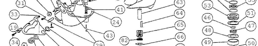
6 MODEL BT TOHATSU 4 STROKE, 3 CYL HP 2014 REF QTY PART DESCRIPTION REF QTY PART DESCRIPTION NO. NO SHIFT ROD GUIDE BT SPACER WATER TUBE EXT. BT TRUARC N ZD BOLT HEX HD M X 40MM UPPER SEAL CARRIER W/SEALS & O RINGS ADAPTER PLATE BT SPIROLOX RR-150S WASHER SPRING LOCK M SEAL INNER BOLT HEX HD M X 35MM SEAL OUTER 6324-S WASHER SPRING LOCK 5/ O RING /32X1 15/16X2 1/ DOWEL PIN 3/16 X 1/ BEARING CARRIER W/SEALS & O RINGS AJ BOLT HEX HD 5/16-18 X 2 1/ O RING /16X5/16X7/ BOLT HEX HD 5/16-18 X 2 3/ WASHER SPRING LOCK 1/ BOLT HEX HD 3/8-16 X 1 1/ BOLT HEX HD 1/4-20 X 3/ VOLUTE WITH GATE BT IMPELLER 6 1/8 W/36 SLEEVE VOLUTE WITH EXHAUST TUBE BT IMPELLER 6 1/8 W/36 SLEEVE, STAINLESS EXHAUST TUBE ASSY MED SHAFT SLEEVE PLASTIC MEDIUM CLIP EXHAUST TUBE IMPELLER TEE KEY - SQUARE NYLOC IMPELLER TEE KEY - 1/2 ROUND WASHER FIBER 3/ SHIM WASHER MEDIUM BOLT HEX HD 3/8-16 X 1/ NUTKEEPER MED/PKG 2 PER BAG BALL END 1/4X10-32 CABLE SHAFT NUT 5/8-18 BRASS LUBE HOSE ASSY INTAKE ASSY 6 1/8 FLANGED W\ GRILL & LINER ZIRC FITTING 1/ LINER 6 1/8 FLANGED GREASE GUN STUD - INTAKE MEDIUM GREASE 10 OZ TUBE 630-AA NYLOC 1/ REVERSE GATE MEDIUM INTAKE PAINTED ONLY MED FLANGED NYLINER 3/8 1D X 1D X 11/ GRILL ROD SPRING GATE PIVOT 3/ GRILL BAR MEDIUM PIN GATE PIVOT 3/8 MEDIUM 171 BRACKET ASSY MORSE W/CLAMP & HARDWARE SHAFT ROLLER BRACKET CABLE SUPPORT NYLOC 1/ SHIM MORSE A ROLLER ASSY CLAMP CHRYS /4 WASHER AN960C FL JD SLOTTED X 5/ SHIFT CAM MEDIUM /4 WASHER AN960C NYLOC 1/ BOLT HEX HD 1/4-20 X 5/ BOLT HEX HD 1/4-20 X 3/ NYLOC BUSHING CAM TORSIONAL DAMPER 5/ WASHER CAM SHIM-CAM CAM ECCENTRIC DRILLED BOLT HEX HD 1/4-20 X 1 PATCH BOLT HEX HD 1/4-20 X 3/4 PATCH SPRING GATE BUMPER GATE BUMPER FIL HD SLOTTED X 1/4 PATCH SHAFT ONLY, BTS, 14T, 24-3/8 LG SHAFT ASSY COMPLETE, BTS, 14T SHAFT ONLY, BTL, 14T 29-3/8 LG SHAFT ASSY COMPLETE, BTL, 14T KEY, TEE WATER PUMP SHAFT BEARING THRUST RING COLLAR BACKFIT THRUST WASHER BEARING 7205B-UA TRUARC SIZE TORQUE 1/4-20 (M6) 8-9 FT-LBS 5/16-18 (M8) 12 FT-LBS 3/8-16 (M10) 22 FT-LBS TILLER STEERING SHIFT CABLE ASSY, 2185 NEUTRAL CABLE ASSY, 1318 BEARING, SEAL, SNAP & O RING KIT


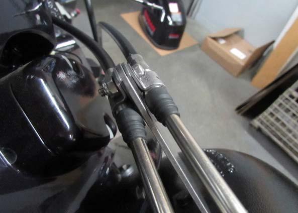
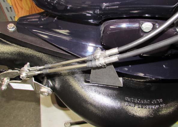
7 TILLER SHIFT CABLE ASSY TOHATSU STARTING SHORT 2209 LONG 2 1 REMOVE NUT REF QTY PART NO. DESCRIPTION CABLE 4 1/2 FT MOR 33C SUPREME LONG CABLE 5 FT MOR 33C SUPREME LONG CABLE END TOHATSU 2014 TILLER

8 TILLER SHIFT CABLE ASSY TOHATSU STARTING SHORT 2209 LONG Cut out the template and tape to the motor pan as shown in the template sheet Remove the lower plastic cover from the tiller steering handle. Remove the shift cable clip and cable Install the 4 1/2 ft. or 5 ft. standard 33C cable provided, using the cable end 2180 and replace the clip. Pass the cable through the routing ring eye (Part 2012) that is threaded throught the template hole and held with a nyloc nut. Attach the lower end of the cable to the jet drive with the ball rod end threaded on the cable as far as it will go and the cable anchor bracket centered and locked. Pass the cable through the routing ring eye (Part 2012). Place the shift handle in forward, solidly in the detent. The reverse gate cam roller must be at the end of the slot in the cam. If these conditions are not met, slide the cable anchor bracket on the jet drive and/or adjust the threaded rod end on the cable. Shift to reverse and back to forward. Do not be concerned if the gate does not reach reverse. There is clearance at this position and water pressure will close the gate. In forward, with the roller at the end of the cam slot, the gate cannot be forcibly rotated toward reverse. Pull on the gate by hand to verify this. Lock the nuts on the cable against the rod ends to complete the adjustment and reassemble the lower cover of the steering arm. CAUTION YOU MUST RETURN THE THROTTLE TO IDLE BEFORE SHIFTING.
9 LARGE SERIES NEUTRAL CABLE ASSEMBLY MODEL AIR, AN, AP, U4-4, U4S-60, U4L-60 SUZUKI 1318 REF QTY PART NO. DESCRIPTION CABLE 5 FT MOR 33C SUPREME BRACKET CABLE SUPT OMC, MORSE SHIM MORSE A CLAMP CHRYS FIL HD SLOTTED X 3/ /4 WASHER AN960C BOLT HEX HD 1/4-20 X 5/ NYLOC NUT HEX BALL END 1/4X10-32 CABLE BOLT HEX HD 1/4-20 X 1 1/ NYLOC 1/
10


11 Cut out the template below and attach to the lower motor pan as shown. Drill through the marked hole with a 3/16 drill. Make sure to drill through where a nyloc nut can be attached inside the pan. Be careful not to drill through any motor part.
12
13
MODEL Z YAMAHA SERIES ASSEMBLY INSTRUCTIONS 40, 50 HP , 30 HP SINCE 1987
 MODEL Z YAMAHA SERIES ASSEMBLY INSTRUCTIONS 40, 50 HP 1983-1994, 30 HP SINCE 1987 1. Place the engine on the transom of you boat so that it is mounted vertically, in the normal fashion. Disconnect the
MODEL W SUZUKI SERIES ASSEMBLY INSTRUCTIONS HP, 1981 TO PRESENT
 MODEL W SUZUKI SERIES ASSEMBLY INSTRUCTIONS 115-140 HP, 1981 TO PRESENT 1. Temporarily clamp the engine on the transom of your boat or an engine stand so that the gearbox can be removed. 2. Disconnect
MODEL AF EVINRUDE / JOHNSON SERIES ASSEMBLY INSTRUCTIONS 2 CYLINDERS, CU. IN., STARTING 1989
 MODEL AF EVINRUDE / JOHNSON SERIES ASSEMBLY INSTRUCTIONS 2 CYLINDERS, 44.99 CU. IN., STARTING 1989 1. Place the engine on the transom of your boat so that it is mounted vertically, in the normal fashion.
MODEL M JOHNSON / EVINRUDE SERIES ASSEMBLY INSTRUCTIONS 4 CYLINDER, 1969 TO 1977
 MODEL M JOHNSON / EVINRUDE SERIES ASSEMBLY INSTRUCTIONS 4 CYLINDER, 1969 TO 1977 1. Place the engine on the transom of your boat so that it is mounted vertically, in the normal position. Remove the engine
MODEL BR SERIES ASSEMBLY INSTRUCTIONS MERCURY HP FOUR STROKE
 MODEL BR SERIES ASSEMBLY INSTRUCTIONS MERCURY 90-115HP FOUR STROKE 1. Place the engine on the transom of your boat so that it is mounted vertically, in the normal fashion. Remove the bolts holding the
MODEL A, H ASSEMBLY INSTRUCTIONS
 MODEL A, H ASSEMBLY INSTRUCTIONS 1. Place the engine on the transom of your boat so that it is mounted vertically, in the normal fashion. Open the access plate in the exhaust housing and disconnect the
OWNER S MANUAL SUPPLEMENT
 OWNER S MANUAL SUPPLEMENT Jet Drive Outboard BF60J / 40 Jet BF90J / 65 Jet Before operating your jet drive outboard for the first time, please read this Owner s Manual. Even if you have operated other
9/8/ MSHZ 2001 / TOP COWLING Yamaha Motor Corporation, U.S.A. All rights reserved.
 9.9MSHZ 00 Page of 47 9/8/04 9.9MSHZ 00 / TOP COWLING 04 Yamaha Motor Corporation, U.S.A. All rights reserved. 9.9MSHZ 00 Page of 47 9/8/04 Part List 9.9MSHZ 00 / TOP COWLING REF - NO PART NUMBER PART
DRIVE_UNIT_ / TRANSOM PLATE
 DRIVE_UNIT_989 989 / TRANSOM PLATE Part List DRIVE_UNIT_989 989 / TRANSOM PLATE REF - NO PART NUMBER PART NAME QUANTITY REMARKS 6T4-4583-00-EK PLATE, TRANSOM 2 6T4-09-00-00 MOUNT, RUBBER 2 2 3 6T4-029-00-00
TILLER HANDLE KIT, P/N and INSTALLATION INSTRUCTION
 TILLER HANDLE KIT, P/N 5005579 and 5005777 INSTALLATION INSTRUCTION APPLICATION This kit is designed for use on 004 (SR) and newer Evinrude E-TEC 75 and 90 HP outboards. DO NOT install on any other models.
Parts Manual Rev. A RZT48 /
 115 91 36-2 Rev. A Parts Manual RZT48 / 96 62001-00 Please read the operator manual carefully and make sure you understand the instructions before using the machine. Gasoline containing a maximum of 10%
9/9/2014 F15MSHC 2004 / TOP COWLING Yamaha Motor Corporation, U.S.A. All rights reserved.
 F5MSHC 00 Page of 6 9/9/0 F5MSHC 00 / TOP COWLING 0 Yamaha Motor Corporation, U.S.A. All rights reserved. F5MSHC 00 Page of 6 9/9/0 Part List F5MSHC 00 / TOP COWLING REF - NO PART NUMBER PART NAME QUANTITY
9/7/2014 F9.9MSHV 1997 / CYLINDER CRANKCASE Yamaha Motor Corporation, U.S.A. All rights reserved.
 F9.9MSHV 997 Page of 45 9/7/04 F9.9MSHV 997 / CYLINDER CRANKCASE 04 Yamaha Motor Corporation, U.S.A. All rights reserved. F9.9MSHV 997 Page of 45 9/7/04 Part List F9.9MSHV 997 / CYLINDER CRANKCASE REF
INSTALLATION INSTRUCTIONS OUTBOARD JET PUMP SECONDARY SHIFT CABLE
 APPLICATION INSTALLATION INSTRUCTIONS OUTBOARD JET PUMP SECONDARY SHIFT CABLE This instruction sheet is intended to supplement the aftermarket jet pump manufacturer s installation instructions. Evinrude
HP Electric PTO Horse Tiller Page 1 of 23 Bolo Tine Assemblies
 12090-8HP Electric PTO Horse Tiller Page 1 of 23 Bolo Tine Assemblies 12090-8HP Electric PTO Horse Tiller Page 2 of 23 Bolo Tine Assemblies 1 1901975001 2 S Tine Holder-welded steel, fits left or right
9/7/2014 T9.9ELRZ 2001 / TOP COWLING Yamaha Motor Corporation, U.S.A. All rights reserved.
 T9.9ELRZ 00 Page of 56 9/7/0 T9.9ELRZ 00 / TOP COWLING 0 Yamaha Motor Corporation, U.S.A. All rights reserved. T9.9ELRZ 00 Page of 56 9/7/0 Part List T9.9ELRZ 00 / TOP COWLING REF - NO PART NUMBER PART
file://c:\programdata\proquestms\partsmanagerpro\print\ ~13~11~5.html
 C60TLRZ 00 file://c:\programdata\proquestms\partsmanagerpro\print\8-9-0 ~~~5.html Page of 6 8/9/0 C60TLRZ 00 / TOP COWLING 0 Yamaha Motor Corporation, U.S.A. All rights reserved. C60TLRZ 00 file://c:\programdata\proquestms\partsmanagerpro\print\8-9-0
EUROPEAN REAR ENGINE RIDER SERIES 20
 Parts Manual for EUROPEAN REAR ENGINE RIDER SERIES 20 MODEL E281320BE E331520KVE McDonough, GA, 30253 U.S.A. Briggs & Startton Yard Power Products Group Copyright 2006 Briggs & Startton Corporation Milwaukee,
5/30/2014 F2.5MSH 0407 / TOP COWLING Yamaha Motor Corporation, U.S.A. All rights reserved.
 F.5MSH 0407 Page of 40 5/30/04 F.5MSH 0407 / TOP COWLING 04 Yamaha Motor Corporation, U.S.A. All rights reserved. F.5MSH 0407 Page of 40 5/30/04 Part List F.5MSH 0407 / TOP COWLING REF - NO PART NUMBER
Parts Manual Rev. B RZT48 /
 115 91 36-2 Rev. B Parts Manual RZT48 / 96 62001-00 Please read the operator manual carefully and make sure you understand the instructions before using the machine. Gasoline containing a maximum of 10%
jbs nfb INSTALLATION INSTRUCTIONS AND OWNERS MANUAL Jet Boat Mechanical Steering HELM MOUNTING KIT SB39462
 MEMBER INSTALLATION INSTRUCTIONS AND OWNERS MANUAL Part # IS-9462, Rev, 07/20 www.seastarsolutions.com jbs nfb Jet Boat Mechanical Steering HELM MOUNTING KIT SB9462 MANUFACTURED BY MARINE ACQUISITION INCORPORATED
J115MLCNB 1982 : CARBURETOR [1/18] Page 1 of 43
![J115MLCNB 1982 : CARBURETOR [1/18] Page 1 of 43](/thumbs/94/118301039.jpg "J115MLCNB 1982 : CARBURETOR [1/18] Page 1 of 43") J115MLCNB 1982 : CARBURETOR [1/18] Page 1 of 43 J115MLCNB 1982 : CARBURETOR [1/18] 0392596 0392596 1 CARB ASSY., Upper, 90 0392597 0392597 1 CARB ASSY., Lower, 90 0392600 0392600 1 CARB ASSY., Upper, 115
J115MLCNB 1982 : CARBURETOR [1/18] Page 1 of 43 J115MLCNB 1982 : CARBURETOR [1/18] 0392596 0392596 1 CARB ASSY., Upper, 90 0392597 0392597 1 CARB ASSY., Lower, 90 0392600 0392600 1 CARB ASSY., Upper, 115
Magnesium Option, Late Model Front Seal, Viton, P/N 67256V Rear Seal, Viton, P/N 67257V Shifter Installed Heat Treated Yoke, P/N
 DESCRIPTION OPTION Magnesium Option, Late Model 80100L Front Seal, Viton, P/N 67256V 80109 Rear Seal, Viton, P/N 67257V 80110L Shifter Installed 80112L Heat Treated Yoke, P/N 62946-6 80119-6 Heat Treated
5/30/2014 F2.5LMHA 0313 / SCHEDULED SERVICE PARTS Yamaha Motor Corporation, U.S.A. All rights reserved.
 F.5LMHA 033 Page of 4 5/30/04 F.5LMHA 033 / SCHEDULED SERVICE PARTS 04 Yamaha Motor Corporation, U.S.A. All rights reserved. F.5LMHA 033 Page of 4 5/30/04 Part List F.5LMHA 033 / SCHEDULED SERVICE PARTS
365L (2001) Page 1 of 36 54" Deck Assembly
 Page 1 of 36 54 Deck Assembly") 365L (2001) Page 1 of 36 54" Deck Assembly 365L (2001) Page 2 of 36 54" Deck Assembly 1 720-0241 1 S Wing Nut Knob 2 703-2817 1 Belt Cover LH 3 703-2816 1 Belt Cover RH 4 747-3306 1 Idler Spring Mounting
365L (2001) Page 1 of 36 54" Deck Assembly 365L (2001) Page 2 of 36 54" Deck Assembly 1 720-0241 1 S Wing Nut Knob 2 703-2817 1 Belt Cover LH 3 703-2816 1 Belt Cover RH 4 747-3306 1 Idler Spring Mounting
B190 8 H.P. Lawn Vacuum (1995) Page 1 of 22 Chute Assembly
 Page 1 of 22 Chute Assembly") 245-315B190 8 H.P. Lawn Vacuum (1995) Page 1 of 22 Chute Assembly 245-315B190 8 H.P. Lawn Vacuum (1995) Page 2 of 22 Chute Assembly Ref # Part Number Qty S/P/F Description 1 681-0068 1 S CHUTE ASSEMBLY
245-315B190 8 H.P. Lawn Vacuum (1995) Page 1 of 22 Chute Assembly 245-315B190 8 H.P. Lawn Vacuum (1995) Page 2 of 22 Chute Assembly Ref # Part Number Qty S/P/F Description 1 681-0068 1 S CHUTE ASSEMBLY
FORD F150 / BRONCO 4X4
 MAY 2,1995 1987-1991 FORD F150 / BRONCO 4X4 ATTACHMENT KIT PARTS LIST ITEM STOCK DESCRIPTION QTY. ITEM STOCK DESCRIPTION QTY. MOUNTING CARTON 1 815000 169 MOUNTING FRAME 1 2 815000 171 PUSHARM DRIVERS
E50PL4SSC 4-Stroke, Elec Start, TNT, 20 IN. shaft 2000 : CAMSHAFT & TIMING [1/21] Page 1 of 44
![E50PL4SSC 4-Stroke, Elec Start, TNT, 20 IN. shaft 2000 : CAMSHAFT & TIMING [1/21] Page 1 of 44](/thumbs/96/129257785.jpg "E50PL4SSC 4-Stroke, Elec Start, TNT, 20 IN. shaft 2000 : CAMSHAFT & TIMING [1/21] Page 1 of 44") E50PL4SSC 4-Stroke, Elec Start, TNT, 20 IN. shaft 2000 : CAMSHAFT & TIMING [1/21] Page 1 of 44 E50PL4SSC 4-Stroke, Elec Start, TNT, 20 IN. shaft 2000 : CAMSHAFT & TIMING [1/21] 1 5031326 1 CAMSHAFT, Intake
E50PL4SSC 4-Stroke, Elec Start, TNT, 20 IN. shaft 2000 : CAMSHAFT & TIMING [1/21] Page 1 of 44 E50PL4SSC 4-Stroke, Elec Start, TNT, 20 IN. shaft 2000 : CAMSHAFT & TIMING [1/21] 1 5031326 1 CAMSHAFT, Intake
PARTS BOOK FLAIL HEADS 90 SIDE MID-MOUNT
 PARTS BOOK FLAIL HEADS 90 SIDE MID-MOUNT 5.0.8 DIAMOND MOWERS, LLC 350 E 60 th St. North Sioux Falls, SD 5704 FOR WARRANTY CALL DIAMOND MOWERS DIRECT: 888-960-0364 OUR TECHNICIANS WILL DIAGNOSE YOUR SITUATION
CYLINDER HEAD CONTINUED ON NEXT FRAME. Ref. Part No. Number Description Qty Remarks
 A1 CYLINDER HEAD 1 4JY-11111-00-00 HEAD, CYLINDER 1 (4JY-11111-01-00).......... 1 2 90116-08394-00 BOLT, STUD.............. 5 3 90176-08026-00 NUT, CROWN............. 5 4 90201-08087-00 WASHER, PLATE...........
RL-F60 PARTS LIST # I USE THIS PARTS LIST FOR: Hoist Serial Number 6745 to
 RL-F60 PARTS LIST # 102692I USE THIS PARTS LIST FOR: Hoist Serial Number 6745 to For older hoists use the following: Parts List No. 102692H for Serial Number 2640 to 6744 IF YOUR HOIST DOES NOT FALL WITHIN
Parts Manual Rev. A
 115 97 79-27 Rev. A Parts Manual Z 248F / 967 844801-00 Please read the operator manual carefully and make sure you understand the instructions before using the machine. Gasoline containing a maximum of
CHEVROLET/GMC K K K3500 4X BLAZER/JIMMY 4X ATTACHMENT KIT
 6-203 August, 2003 1988-1999 CHEVROLET/GMC K1500 - K2500 - K3500 4X4 1992-1994 BLAZER/JIMMY 4X4 81001 ATTACHMENT KIT PARTS LIST ITEM STOCK DESCRIPTION QTY. ITEM STOCK DESCRIPTION QTY. 81001 MOUNTING CARTON
REF. NO. DESCRIPTION TOP COWLING 2 MOLDING, AIR DUCT 3 RIVET 4 SEAL 5 HOLDER, CLAMP BAND 6 BOLT, WITH WASHER 7 HOOK
 SUZHOU ALLPASS MACHINERY CO.,LTD Add:No.85,Jishui Road,Jinfeng Industrial Park,Mudu Town,Suzhou 215102,Jiangsu,P.R.China T15 SPARE PARTS EXPLODED DRAWING FIG. 1 1 TOP COWLING TOP COWLING 2 MOLDING, AIR
MK-5000G exploded VieW
 Frame accessories 38 cutting head Pump Assembly 39 connecting linkage foot pedal linkage 40 curtain blade guard 41 ENGINE Assembly 42 PARTS LIST A Frames - - A1 Frame, MK-5000 Main 1 155541 B Pivot Bracket
21A Tuffy Tiller Page 1 of 18 Bolo Tines & Wheels
 21A-510-081 Tuffy Tiller 12155 Page 1 of 18 Bolo Tines & Wheels 21A-510-081 Tuffy Tiller 12155 Page 2 of 18 Bolo Tines & Wheels Ref # Part Number Qty S/P/F Description 1 1100046 16 S Bolt-Hex Head, 3/8-16
INSTRUCTIONS. Disassembly. Shifter Cam Assembly. Shifter Forks
 INSTRUCTIONS Disassembly To protect against accidental start-up of vehicle, always disconnect the negative battery cable before working on the motorcycle. Failure to disconnect the battery cable could
KIT # CSS-C SUSPENSION LIFT KIT
 14385 Veterans Way Moreno Valley, CA 92553 Phone: (951) 571-0212 Fax: (951) 571-0215 2001-2010 CHEVROLET SILVERADO 1500 AND 2500 HD 4WD AND 2WD PICK-UP 1999-2010 CHEVY 2500 4WD PICK-UPS 2001-2010 2500
REAR ENGINE RIDER 42 MOWER SERIES 22
 Parts Manual for REAR ENGINE RIDER MOWER SERIES MODELS 1BVE CONTENTS DESCRIPTION PAGE(S) DESCRIPTION PAGE(S) WHEELS- TIRES... - FRONT END, STEERING.... - MAIN CASE... - DIFFERENTIAL, R. H. FENDER... 8-9
Loader Backhoe Front Axle Parts 2WD & 4WD
 Loader Backhoe Front Axle Parts 2WD & 4WD SECTION G LOADER BACKHOE FRONT AXLE PARTS CASE 2WD AXLE PARTS G2 - G5 CARRARO APPLICATIONS G6 - G25 FRONT AXLE KITS G23 - G25 CASE POWER STEERING VALVES & PUMPS
CHEVROLET/GMC K10 - K20 - K BLAZER/JIMMY/SUBURBAN/CREWCAB CAB CHASSIS 4X ATTACHMENT KIT
 1973-1987 CHEVROLET/GMC K10 - K20 - K30 1973-1991 BLAZER/JIMMY/SUBURBAN/CREWCAB CAB CHASSIS 4X4 ATTACHMENT KIT PARTS LIST ITEM STOCK DESCRIPTION QTY. ITEM STOCK DESCRIPTION QTY. MOUNTING CARTON 1 815000
Next, set the bar level and tighten it down. Do this on both the driver and passenger sides.
 Next, set the bar level and tighten it down. Do this on both the driver and passenger sides. Using two tape measures, measure the outside width at the front and the rear of the tubes. The front dimension
INSTALLATION GUIDE Bolt-On Drag-Race Strut Clip Chevy II
 INSTALLATION GUIDE 7702 Bolt-On Drag-Race Strut Clip 1962-67 Chevy II Description: STRUT CLIP 4130 BOLT ON 62-67 CHEVY II, INCLUDES 4130 ROUND TUBE FRAME CLIP, DOUBLE-ADJUSTABLE STRUTS, ADJUSTABLE-HEIGHT
E70PL4EEC 1999 : CAMSHAFT [1/23] Page 1 of 49
![E70PL4EEC 1999 : CAMSHAFT [1/23] Page 1 of 49](/thumbs/96/129257940.jpg "E70PL4EEC 1999 : CAMSHAFT [1/23] Page 1 of 49") E70PL4EEC 1999 : CAMSHAFT [1/23] Page 1 of 49 E70PL4EEC 1999 : CAMSHAFT [1/23] 1 5030657 1 CAMSHAFT 2 5030658 1 PLATE, Camshaft thrust 3 5030549 1 SEAL, Camshaft 4 5030989 2 BOLT, Plate 5 5030663 8 ARM,
E70PL4EEC 1999 : CAMSHAFT [1/23] Page 1 of 49 E70PL4EEC 1999 : CAMSHAFT [1/23] 1 5030657 1 CAMSHAFT 2 5030658 1 PLATE, Camshaft thrust 3 5030549 1 SEAL, Camshaft 4 5030989 2 BOLT, Plate 5 5030663 8 ARM,
RJS2020 SPORT 3.2 1/10 PAN CAR KIT LESS ELECTRICS
 RJS2020 SPORT 3.2 1/10 PAN CAR KIT LESS ELECTRICS THANKS FOR BUYING THE RJ SPEED 1/10 SPORT 3.2 KIT. THE ASSEMBLY WILL NOT BE DIFFICULT IF YOU READ THE TEXT, LOOK AT THE PICTURES, AND THE EXPLODED VIEW
Mfg. No: P216020KWV, 21" 6 TP Steel Deck Series
 Parts Manual Mfg. No: 7800557 P216020KWV, 21" 6 TP Steel Deck Series Copyright Briggs and Stratton. All Rights reserved 28-Sep-2018 Model Components Table Of Contents Page Accessory Recycling Kits..............................................................................
136R616G190 Lawn Tractor FST-16 (1996) Page 1 of 27 42" Mowing Deck
 Page 1 of 27 42 Mowing Deck") 136R616G190 Lawn Tractor FST-16 (1996) Page 1 of 27 42" Mowing Deck 136R616G190 Lawn Tractor FST-16 (1996) Page 2 of 27 42" Mowing Deck 3 97600A 1 S 42" Deck Ass'y. Code: N notates a new part (not previously
136R616G190 Lawn Tractor FST-16 (1996) Page 1 of 27 42" Mowing Deck 136R616G190 Lawn Tractor FST-16 (1996) Page 2 of 27 42" Mowing Deck 3 97600A 1 S 42" Deck Ass'y. Code: N notates a new part (not previously
250P Manure Spreader
 0P Manure Spreader Illustrated Parts Breakdown Page - Page Page Page Page Page Page Page Page Page Page Page Page Page Page - Page Page Page 0 Complete Front End PTO/Jack/Hitch Assembly Front Pulley Assembly
Bearing and Seal Installation Tool T1 Clutch Assembly Stand X X X X Shift Handle Tool X X T Bearing Cup Driver X X
 Bravo Sterndrive Bravo Sterndrive Tool Application Chart Part No. Description Bravo One Bravo Two Bravo Three Blackhawk 11 24156 Hex Nut 12 34961 Washer 91 12427 Shift Cable Adjustment Tool 91 17256 Bearing
WJ JACUZZI ENERGIZER PARTS LIST
 WJ JACUZZI ENERGIZER PARTS LIST BAG KIT QTY PART # DESCRIPTION ITEM CK. 1 B-1007 THRUST BEARING 8 F20LW LOCKWASHER, 5/16 8 F21CS HEX HEAD CAP SCREW, 5/16-18 X 1-1/4 1 K-4007 SHIM KIT W / 3 EXTRA.060 SHIMS
CYLINDER HEAD CONTINUED ON NEXT FRAME. Ref. Part No. Number Description Qty Remarks
 A1 CYLINDER HEAD 1 4JY-11111-00-00 HEAD, CYLINDER 1 (4JY-11111-01-00).......... 1 2 90116-08394-00 BOLT, STUD.............. 5 3 90176-08026-00 NUT, CROWN............. 5 4 90201-08087-00 WASHER, PLATE...........
Bombardier Recreational Products Inc.
 Bombardier Recreational Products Inc. REMOTE CONTROL CONVERSION KIT, P/N 5035775 INSTALLATION INSTRUCTIONS APPLICATION This kit is designed for use on 000 (SS) and newer Evinrude or Johnson 5 and 30 HP
5/29/2014 3MSHY 2000 / CYLINDER CRANKCASE Yamaha Motor Corporation, U.S.A. All rights reserved.
 Page 1 of 22 3MSHY 2000 / CYLINDER CRANKCASE Page 2 of 22 Part List 3MSHY 2000 / CYLINDER CRANKCASE REF - NO PART NUMBER PART NAME QUANTITY REMARKS 1 6L5-W0090-01-1S CRANK CYLINDER ASSY 1 2 6L5-15100-00-1S
CLUTCH CONTENTS SERVICE DIAGNOSIS. (a) Worn or damaged disc assembly. (b) Grease or oil on disc facings. (c) Improperly adjusted cover assembly.
 Worn or damaged disc assembly. (b) Grease or oil on disc facings. (c) Improperly adjusted cover assembly.") CLUTCH CONTENTS -GROUP 6 Page CLUTCH HOUSING ALIGNMENT... 6 CLUTCH PEDAL FREE PLAY 1 CLUTCH RELEASE BEARING 5 CLUTCH RELEASE FORK... 5 CLUTCH SERVICING 2 PILOT BUSHING CRANKSHAFT TO TRANSMISSION DRIVE
CLUTCH CONTENTS -GROUP 6 Page CLUTCH HOUSING ALIGNMENT... 6 CLUTCH PEDAL FREE PLAY 1 CLUTCH RELEASE BEARING 5 CLUTCH RELEASE FORK... 5 CLUTCH SERVICING 2 PILOT BUSHING CRANKSHAFT TO TRANSMISSION DRIVE
5/29/2014 3MSHU 1996 / CYLINDER CRANKCASE Yamaha Motor Corporation, U.S.A. All rights reserved.
 Page 1 of 22 3MSHU 1996 / CYLINDER CRANKCASE Page 2 of 22 Part List 3MSHU 1996 / CYLINDER CRANKCASE REF - NO PART NUMBER PART NAME QUANTITY REMARKS 1 6L5-W0090-01-4D CRANK CYLINDER ASSEMBLY 1 2 6L5-15100-00-94
First, check and record the camber and caster readings, they will be adjusted later.
 First, check and record the camber and caster readings, they will be adjusted later. The caliper-mounting bosses are machined perpendicular to the spindle so they are an excellent place for the level.
2008, K&M NEWSPAPER SERVICES, INC. INSERTER 2299 INSERTER
 99 INSERTER - - - 800-88-0 COMPLETE FIXED POCKET WALL ITEM PART # DESCRIPTION QUANTITY KMS 0CW COMPLETE POCKET WALL COMES ASSEMBLED WITH YOUR CHOICE OF GRIPPERS & PADDLES - - - 800-88-0 FIXED POCKET WALL
JEEP Wrangler JK/JKU Swing-A-Way Tire Carrier/RotoPpax WARNINGS/CAUTIONS NOTE. INSTALLATION INSTRUCTIONS 2 Door Models 85209
 JEEP Wrangler JK/JKU Swing-A-Way Tire Carrier/RotoPpax 2007-2017 INSTALLATION INSTRUCTIONS Item Kit No. 2 Door Models 85209 4 Door Models 85209 WARNINGS/CAUTIONS These instructions are for both the can
S/N 880, ,000 Page 1 of 84 Air Cleaner
 1641 S/N 880,001-899,000 Page 1 of 84 Air Cleaner 1641 S/N 880,001-899,000 Page 2 of 84 Air Cleaner 1 BS-805406 2 S Screw, Sems 2 BS-805655 1 S Gasket, Air Cleaner 3 BS-807796 1 S Bracket, Air Cleaner
320 Series Models 325, 326, 327
 0 Series Models,, ROTARY MOWER Published 0/ PARTS MANUAL SECTION An Operator s Manual was shipped with the equipment. The Operator s Manual is an integral part of the safe operation of this machine and
IMCO SCX SERIES INFORMATION, OPERATION & MAINTAINANCE
 IMCO SCX SERIES INFORMATION, OPERATION & MAINTAINANCE Warning! Warning! Warning! Danger! Warning! 1. SCX & SCX4 Drives will not fit on a standard gimbal helmet, IMCO HELMET: #05-8025 Black or #05-8027
HORSE III 8HP ROTO TILLER (S/N ) Page 1 of 25 Bolo Tine Assemblies
 Page 1 of 25 Bolo Tine Assemblies") HORSE III 8HP ROTO TILLER (S/N 640000-855638) Page 1 of 25 Bolo Tine Assemblies HORSE III 8HP ROTO TILLER (S/N 640000-855638) Page 2 of 25 Bolo Tine Assemblies 1 GW-2415 2 S/F TINE HOLDER- welded steel.
HORSE III 8HP ROTO TILLER (S/N 640000-855638) Page 1 of 25 Bolo Tine Assemblies HORSE III 8HP ROTO TILLER (S/N 640000-855638) Page 2 of 25 Bolo Tine Assemblies 1 GW-2415 2 S/F TINE HOLDER- welded steel.
Parts Manual Rev. A
 115 97 25-27 Rev. A Parts Manual Z 242F / 967 844702-00 Please read the operator manual carefully and make sure you understand the instructions before using the machine. Gasoline containing a maximum of
Max IV Rear Axle Replacement For models after Serial Number and all rear splined axle replacements.
 Max IV Rear Axle Replacement For models after Serial Number 19089 and all rear splined axle replacements. 10/8/03 Max IV Snap Ring Rear Axle replacement.doc Tools required: 9/16 Wrench 6 Extension Steel
CLUTCH. Section IV DATA AND SPECIFICATIONS CHRYSLER SERVICE MANUAL. Page. Clutch Pedal Adjustment 74. Clutch Disassembly 77. Clutch Assembly 78
 CLUTCH 73 Section IV CLUTCH Page Clutch Pedal Adjustment 74 Clutch Disassembly 77 Clutch Assembly 78 Service Diagnosis 81 DATA AND SPECIFICATIONS MODEL TYPE 1376 (Borg-Beck) Single Plate, Dry Disc FACINGS
SEC PARTS MANUAL SERIAL NUMBERS: BODY: MAST: GRABBER: MFG. DATE: Made in the U.S.A.
 SEC PARTS MANUAL SERIAL NUMBERS: BODY: MAST: GRABBER: MFG. DATE: Made in the U.S.A. TABLE OF CONTENTS WARRANTY WARRANTY REGISTRATION FORM TABLE OF CONTENTS PAGE I PAGE II PAGE III PARTS SECTION 1 HYDRAULICS
EASTMAN STRIPER PARTS MANUAL
 EASTMAN STRIPER PARTS MANUAL Including Kawasaki Model FC180V Engine Parts Manual for Eastman Industries Commercial Mower Model ST21-K Table of Contents Parts Page Mower Parts 2-10 Cylinder/Crankcase 11-12
INSTALLATION AND PARTS MANUAL
 INSTALLATION AND PARTS MANUAL FOR JOHN DEERE PS TRACTORS NOTE: This manual covers mounting and control group installation, and parts specific to this winch on the specified tractor. For all other winch
FIGURE 1-3. LEFT OP CONTROL BOX. MARCH/2011 HST-1-3, Page 1 of 2
 FIGURE 1-3. LEFT OP CONTROL BOX MARCH/2011 HST-1-3, Page 1 of 2 FIGURE 1-3. LEFT OP CONTROL BOX MARCH/2011 HST-1-3, Page 2 of 2 FIGURE 1-3A. LEFT OP CONTROL BOX MARCH/2011 HST-1-3A, Page 1 of 2 FIGURE
Assembly Manual. 1/10th Formula 1 Car
 Assembly Manual 1/10th Formula 1 Car Center Pivot Bag 1 3374 - Center Pivot Socket 40194 - Hard Anodized Alum Pivot ball 3254-2-56 *Note - Sometimes it is helpful to slightly over-tighten the top clamp
LAND MAINTENANCE REPAIR PARTS MANUAL BUSH HOG MODEL: 307 SECTION: 16
 BUSH HOG LAND MAINTENANCE REPAIR S MANUAL MODEL: 0 SECTION: P.O. Box 0 Selma, AL 0-0 () - () -00 Parts Ordering -00-0- Fax -00-- www.bushhog.com BUSH HOG / LAND MAINTENANCE REPAIR S MANUAL SEPTEMBER, 0
INSTALLATION GUIDE TCP RCKM-01
 READ ALL INSTRUCTIONS COMPLETELY AND THOROUGHLY UNDERSTAND THEM BEFORE DOING ANYTHING. CALL TOTAL CONTROL PRODUCTS TECH SUPPORT (916) 388-0288 IF YOU NEED ASSISTANCE. INSTALLATION GUIDE TCP RCKM-01 Manual
Ford Torino Small Block Rack Kit Instructions
 1968-69 Ford Torino Small Block Rack Kit Instructions 8012290-01 Unisteer offers a limited warranty against all manufacturer defects of their kits and supplied parts. Unisteer will not honor any warranty
Page 1 of HP B&S Vanguard Engine
 1405 Page 1 of 41 14 HP B&S Vanguard Engine 1405 Page 2 of 41 14 HP B&S Vanguard Engine Ref # Part Number Qty S/P/F Description BS-28Q777-0647-E1 1 14 HP B&S Vanguard Engine 1 BS-496412 1 Cylinder Assembly
MZ 52LE. Parts Manual. Zero Turn Mower /
 Parts Manual MZ 52LE Zero Turn Mower / 9677406-00 Please read the operator manual carefully and make sure you understand the instructions before using the machine. When you need spare parts or support
M-ZT 61. Parts Manual. Zero Turn Mower /
 Parts Manual M-ZT 61 Zero Turn Mower / 967177008-01 Please read the operator manual carefully and make sure you understand the instructions before using the machine. When you need spare parts or support
REAR ENGINE RIDER EUROPEAN SERIES 22
 Parts Manual for REAR ENGINE RIDER EUROPEAN SERIES 22 MODELS E2822BE E2822BE E1522KVE CONTENTS DESCRIPTION PAGE(S) DESCRIPTION PAGE(S) WHEELS, TIRES...2, DRIVE DISC ASSEMBLY... 22 FRONT END, STEERING...4,
Service Parts. Doosan 11.1 L. Engine. Engine Model: Generator Models: 180/200REZX 180/200RZX TP /09
 Service Parts Engine Engine Model: Doosan. L Generator Models: 80/00REZX 80/00RZX TP-0 /09 Table of Contents Introduction... Numbering System Significance... Illustrations... How to Find Part Numbers...
2. With the rear door open remove pull-style clip from the passenger side just below the door latch.
 LoD Offroad FJ Cruiser Rear Bumper with Tire Carrier Installation Instructions 1. Begin with removing factory spare from the rear door. 2. With the rear door open remove pull-style clip from the passenger
Tools Needed: Class 8.8 Class MM 55ft/lbs 75ft/lbs 14MM 85ft/lbs 120ft/lbs 16MM 130ft/lbs 165ft/lbs 18MM 170ft/lbs 240ft/lbs
 921788000 JEEP JK 6 LONGARM Rough Country recommends a certified technician install this system. In addition to these instructions, professional knowledge of disassemble/reassembly procedures as well as
1989 Jeep Cherokee. STEERING COLUMN' '1989 STEERING Jeep Steering Columns STEERING COLUMN STEERING Jeep Steering Columns
 STEERING COLUMN 1989 STEERING Jeep Steering Columns DESCRIPTION All models use collapsible steering columns. All columns have integral ignition switch and locking device. Optional tilt wheel is available
Installation Instructions
 Equipment Required: Fastener Kit: F Wrenches: 3/4, 15/16 Drill Bits: 1/4 Other Tools: Drill WARNING: Under no circumstances do we recommend exceeding the towing vehicle manufacturers recommended vehicle
4ACMH 04 (6E03) 5CMH 04 (6E33)
 5CMH 04 (6E33)") MH 04 (6E03) MH 04 (6E33) 1C6E0-700E1 ( 2C6E0-700E1 ) FOREWORD This Parts Catalogue is related to the parts for the model(s) on the cover page. When you are ordering replacement parts, please refer to
MH 04 (6E03) MH 04 (6E33) 1C6E0-700E1 ( 2C6E0-700E1 ) FOREWORD This Parts Catalogue is related to the parts for the model(s) on the cover page. When you are ordering replacement parts, please refer to
Tractor S/N 239, ,005 Page 1 of 76 42" Deck Assembly
 2140 Tractor S/N 239,001-326,005 Page 1 of 76 42" Deck Assembly 2140 Tractor S/N 239,001-326,005 Page 2 of 76 42" Deck Assembly 1 17861A 1 S Skirt, Extension 2 17961 1 S Skirt, Short 3 603-0181 1 S Plate
TT8101 Rotary Tedder
 TT0 Rotary Tedder Illustrated Parts Breakdown Page Front End Page Page Transport Axle Assembly Cylinder Linkage Page Guards Page Page Page Page Transport Lock Assembly Lift Frame Assembly Center Tunnel
OPERATION MANUAL INTERNAL GEAR PUMP. Models: NG-H, NG-HL, NG-K, NG-KK, NG-L, NG-LQ, NG-LL, NG-LS, NG-Q, NG-QS. Tel: Fax:
 OPERATION MANUAL INTERNAL GEAR PUMP Models: NG-H, NG-HL, NG-K, NG-KK, NG-L, NG-LQ, NG-LL, NG-LS, NG-Q, NG-QS. 1 Contents Pump Designation System Maintenance Thrust bearing adjustment Pressure Relief Valve
FRONT RACK, BODY PANEL, AND HEADLIGHT ASSEMBLIES
 FRONT RACK, BODY PANEL, AND HEADLIGHT ASSEMBLIES 0747-506 1 2506-107 1 Rack, Front - Assembly (inc. 2) 2 0411-576 1 Decal, Warning - Load 3 0441-592 4 Bushing 4 8410-835 4 Screw, Cap 5 0423-669 4 Spacer
PARTS MANUAL SECTION. Models 295, 296, 297, 1297 ROTARY MOWER
 0 Series Models,,, ROTARY MOWER Published 0/ PARTS MANUAL SECTION An Operator s Manual was shipped with the equipment. The Operator s Manual is an integral part of the safe operation of this machine and
RL-G70 PARTS LIST # I USE THIS PARTS LIST FOR: Hoist Serial Number 6597 to
 RL-G70 PARTS LIST # 102693I USE THIS PARTS LIST FOR: Hoist Serial Number 6597 to For older hoists use the following: Parts List No. 102692H for Serial Number 2485 to 6596 IF YOUR HOIST DOES NOT FALL WITHIN
Retriever 360G/P. 5/92 revised 2/01 FORM NUMBER
 Retriever 360G/P PARTS LIST Advance MODELS 56468470, 56468480 This parts list is for machines after serial number 505073 All models covered in this manual are OBSOLETE 5/92 revised 2/01 FORM NUMBER 56042267
Parts Manual Rev. A
 115 96 28-27 Rev. A Parts Manual Z 242F / 967 271802-00 Please read the operator manual carefully and make sure you understand the instructions before using the machine. Gasoline containing a maximum of
Before starting installation
 Before starting installation The load rating for these tire-can/tire carriers is a MAXIMUM of 175 lbs. Please be aware that some tire and wheel combinations along with gas cans and hi-lift jacks can exceed
BUSH HOG LAND MAINTENANCE REPAIR PARTS MANUAL
 BUSH HOG LAND MAINTENANCE REPAIR PARTS MANUAL MODEL: DM7, DM8, DM9 SECTION: 43 2501 Griffin Ave. Selma, AL 36703 (334) 872-6261 (334) 874-2700 Parts Ordering 1-800-304-2836 Fax 1-800-572-1784 www.bushhog.com
INSTALLATION INSTRUCTIONS
 INSTALLATION INSTRUCTIONS --1075 North Ave. Sanger, CA 93657-3539 local: 559-875-0222 fax: 559-876-2259 toll free: 800-445-3767-- 2505 Lowering Spindle Assembly Installation Instructions ½ TON SILVERADO
PARTS CATALOG ODYSSEY INCLUDES MOWER
 PARTS CATALOG 8-3350 ODYSSEY INCLUDES MOWER INDEX PAINT ENGINES GENERAL INFO PRODUCT IDENTIFICATION NUMBERS (P.I.N.) OR SERIAL NUMBERS (S/N) ENGINE MODEL, SERIAL AND SPECIFICATION NUMBERS TRACTOR MODEL
RC-200EX / RC-150EX Rim Clamp Tire Changer
 RC-200EX / RC-150EX Rim Clamp Tire Changer For servicing motorcycle and ATV tire/wheel assemblies as well as automotive and most light truck tire/wheel assemblies (holds 6 to 8-inch wheels for manual tire
INSTALLATION INSTRUCTIONS 88029
 INSTALLATION INSTRUCTIONS 88029 FOR SUSPENSION SYSTEMS RS6503: JEEP WRANGLER (TJ) READ ALL INSTRUCTIONS THOROUGHLY FROM START TO FINISH BEFORE BEGINNING INSTALLATION REV F IMPORTANT NOTES! WARNING: This
REMOTE CONTROL CONVERSION KIT, P/N INSTALLATION INSTRUCTIONS
 REMOTE CONTROL CONVERSION KIT, P/N 5035779 INSTALLATION INSTRUCTIONS APPLICATION This kit is designed for use on 003 (ST) and newer Johnson 4, 5, 6 HP (38 cc) 4-Stroke outboards. DO NOT install on any
Parts Manual Rev. A RZT54 /
 115 93 37-27 Rev. A Parts Manual RZT54 / 967 672101-00 Please read the operator manual carefully and make sure you understand the instructions before using the machine. Gasoline containing a maximum of
Champion Series Zero-Turn Riders & Mower Decks
 Parts Manual Champion Series Zero-Turn Riders & Mower Decks HP Tractors Mfg. No. Description Champion, HP Zero-Turn Rider Champion, HP Zero-Turn Rider (CE) 0HP Tractors Mfg. No. Description Champion, 0HP