MODEL Z YAMAHA SERIES ASSEMBLY INSTRUCTIONS 40, 50 HP , 30 HP SINCE 1987
|
|
|
- Linette Edwards
- 6 years ago
- Views:
Transcription
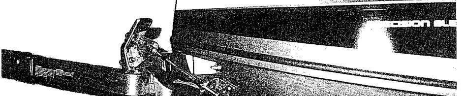
1 MODEL Z YAMAHA SERIES ASSEMBLY INSTRUCTIONS 40, 50 HP , 30 HP SINCE Place the engine on the transom of you boat so that it is mounted vertically, in the normal fashion. Disconnect the shift rod by backing off the hex nuts, lower front. Remove the bolts holding the gearbox to the exhaust housing and remove the gearbox assembly. 2. Remove the water pump assembly from the propeller drive, including the lower stainless steel plate, gaskets, impeller drive key, and dowel pins. 3. Install the jet driveshaft assembly into the spiral pump housing locking it in place with the two #10-24 x 5/8 screws and lockwashers. Use grease on the threads. 4. Install the water pump assembly on top of the 1-5/16 inch thick aluminum adapter and stainless steel plate. Be sure also, to install the water pump impeller brass tee key (Woodruff key no longer used), and dowel pins. Lock in place using two 5/16-18 x 2-1/4 and two 5/16-18 x 2-3/4 bolts and lockwashers. Grease the threads. 5. Push the sponge rubber sleeve up inside the pivot tube to prevent the disconnected shift rod from rattling. 6. The large 3/4 inch adapter plate is attached to the exhaust housing to hold the jet drive. Two 6 x 16mm dowels locate the plate, four M10 x 35mm bolts with lockwashers and one M8 x 30mm bolt with lockwasher secure it. Grease the bolt threads. 7. Next, attach the jet drive to the motor. Two 3/16 x 1/2 dowel pins center the jet drive on the adapter plate. Four 5/16-18 x 2-3/4 bolts and lockwashers from below and one 3/8-16 x 1-1/4 bolt from above rear, are used. Grease the bolt threads, driveshaft spline generously, and rubber water tube pilot and guide the jet into place. Tighten the five bolts. 8. Next, install the impeller. Grease the shaft threads, key and impeller bore. Place the plastic sleeve inside the impeller, hold the key in the nose of the impeller with your forefinger and slide onto the driveshaft. Install the nine shim washers and nut retainer on the shaft, up against the impeller, and bring the nut up snug by hand. Be careful that the retainer does not fall into the thread groove and jam the nut. Place the water intake in position and secure with 2 bolts. Observe the clearance between the impeller blade edge and the intake liner. Then remove the intake. When, after use in sand and gravel, the blade clearance becomes more than about 1/32 inch between the impeller edge and the water intake liner, one or more of the stainless shim washers can be transferred from the bottom stack to the top of the impeller, which moves the impeller down into the tapered casing to reduce the clearance. Shims should not be used above the impeller on new installations, where no wear has occurred, unless the blade clearance exceeds 1/32 inch. Insufficient blade clearance will do more harm than good from any performance gains it might provide. Then bump the nut with a wrench. If the ears of the retainer do not line up with the flats on the nut, spin the nut off, turn the retainer over and tighten the nut again. In one of these two positions you will have alignment and can fold the ears up against the nut to retain it. The flat in the retainer is angled to the ears to allow this. When the impeller clearance is satisfactory, bump the nut up snug with a wrench. If the ears of the retainer do line up with the flats on the nut, spin the nut off, turn the retainer over and tighten the nut again. In one of these two positions you will have alignment and can fold the ears up against the nut to retain it. The flat in the retainer is angled to the ears to allow this. 1
2 MODEL Z YAMAHA SERIES ASSEMBLY INSTRUCTIONS 40, 50 HP , 30 HP SINCE Place the intake casing in position with the lower end at the rear and tighten the six 1/4-20 x 3/4 hex head bolts. No lockwashers are used. Grease the threads. See diagram page If your jet drive was ordered for use with a steering tiller handle, see attached page Shift Rod and Handle Assembly Instructions, pages If your motor is equipped for remote controls, proceed as follows: Attach the shift cable and cable anchor bracket to the jet drive. Using a light finger pressure on the gate, move the gate toward reverse until the cam roller is nested in the neutral notch of the cam. Adjust the shift cable end and the cable anchor bracket on the jet drive such that the roller is in the neutral notch when the shift handle is in neutral. Tighten hardware. Shift to forward. The roller should be well onto the flat section of the cam such that the gate cannot be forcibly rotated toward reverse. Pull on the gate by hand to verify this. If this forward lock condition is not met, readjust the cable positions, giving less importance to the roller position in neutral. 12. If the neutral position is too far out of adjustment, the tendency of the gate to move toward reverse, under water pressure, will put tension on the cable in neutral. In some remote control boxes, this makes it difficult to reengage the shift mode with the motor running in the high speed idle, cold start setting. It is then necessary to stop the motor, operate the shift handle to engage the shifting pin and then restart the motor. Proper cable adjustment will prevent this problem but it is most important that the forward locking condition be met if a compromise is to be made. 13. When converting to jet drive, your motor will have to be raised to height shown in diagram on page 3, using a straight edge under the boat. Test run the boat and then raise or lower the motor 5/16 inch at time to obtain the best results. The motor has four sets of upper mounting holes. You will use one set to begin with. Mark pencil lines on the boat transom through the other sets. Then if you wish to go up or down 5/16 inch, you can drill one alternate set of holes 5/16 inch up or down from the pencil marks. By alternating between two sets of transom holes and the four sets of motor holes, the motor can be moved in 5/16 increments over almost one inch. The transom height should be about 21 inches measured vertically from the boat bottom for short shaft motors and 26 inches for long shaft. If you raise it too much it will suck air and cavitate, either on start up or when banking on turns. When cavitating, the motor overspeeds in spurts and shakes considerably in the motor mount. This is not a normal condition and should be avoided by proper adjustment of motor height on each individual boat. If you lower it too much you will have excessive drag, therefore mount the motor as high as possible without allowing cavitation. CAUTION 2
3 MODEL Z YAMAHA SERIES ASSEMBLY INSTRUCTIONS 40, 50 HP , 30 HP SINCE 1987 When starting the engine for the first time, watch to see that cooling water comes out of the small hole at the rear side of engine just below the powerhead. This is to check your assembly of the cooling water pump and its connections. The cooling system can be flushed by removing the slotted screw next to the grease fitting. A hose coupling No A1 is available from a Yamaha dealer. Turn on the water gently, start the motor, set to idle and watch for cooling water at the tell tale. Adjust water pressure if needed. Replace the screw after flushing. SETTING ENGINE HEIGHT Straight Edge MAINTENANCE AND LUBRICATION See last page. MODEL ZSM 40 HP SHIFT ROD AND HANDLE ASSEMBLY INSTRUCTIONS SHORT SHAFT #1215, LONG SHAFT # Place the pressed steel shift handle on the motor shift handle and clamp in place, spaced ¾ inch as shown in the diagram. Using a 3/16 inch drill, drill through the shift handle for the #10-32 fil head screws. Install the screws and fiber lock nuts. Attach the black knob on top of the apcer and tighten the bolt. 2. Next, attach the shift rod. Using a light finger pressure on the reverse gate, move the gate toward reverse until the cam roller is nested in the neutral notch of the cam. Adjust the length of the rod so that with the handle in neutral, the roller on the reverse gate is in the neutral notch of the cam, with the gate held up by hand. 3. Shift to forward. The roller should be at the end of the slot in the cam such that the gate cannot be forcibly rotated toward reverse. Pull on the gate by hand to verify this. If this forward lock position is not met, readujust the rod length, giving less importance to neutral. Lock the rod end nuts. 4. Return to page to, and proceed with setting motor height. 3

4 MODEL Z YAMAHA SERIES ASSEMBLY INSTRUCTIONS 40, 50 HP , 30 HP SINCE 1987 Specialty Manufacturing Company OUTBOARD JETS 2035 Edison Avenue San Leandro, CA
5 MODEL Z30SM 30 HP Shift Handle and Cable Assembly Instructions Short Shaft #1261 Long Shaft # Cut out the paper template, bottom of this page. Align the template on the motor cowl and hold in place with masking tape. Drill 2-3/16 inch holes and remove template. 2. Attach the cable anchor bracket using 2- #10-32 x 1 fil head screws and fiber lock nuts. 3. Place the cable end ball bracket in position on the shaft handle. Adjust the position so that it does not rock and will not put a strain on the plastic handle when the through bolts are tightened. Refer to the picture on page 6. Hold in this position using a C clamp on one of the ears. Drill a ¼ inch hole through the bracket and handle on the exposed ear. 4. Install a ¼ inch bolt with a plain washer under the head and a lockwashwer under the nut. Tighten the nut, remove the clamp and drill the 2nd hole. Install the 2nd bolt and tighten the nut. 5. Attach the shift cable and cable anchor bracket to the jet drive, using 2-1/4-0 x 5/8 bolts and flat washers. Move the bracket forward and tighten the bolts. Using a light finger pressure on the gate, move the gate toward reverse until the cam roller is nested in the neutral notch of the cam. Adjust the shift cable ends such that the roller is in the neutral notch when the shift handle is in neutral. Tighten hardware. Shift to forward. The roller should be at the end of the slot in the cam such that the gate cannot be forcibly rotated toward reverse. Pull on the gate by hand to verify this. If this forward lock condition is not met, readjust the cable positions, giving less importance to the roller position in neutral. 6. Return to page 2, and proceed with setting motor height. CUT OUT THIS SECTION ALSO
6


7 MODEL "Z30SM" 30 HP
8 BEARING LUBRICATION MAINTENANCE AND LUBRICATION OUTBOARD JET DRIVE A grease gun and tube of grease is supplied with your jet drive. We recommend greasing the bearing every 10 hours. Make greasing a part of your cleanup after the days use. Pump in just enough grease to fill the lube hose. Then reconnect the lube hose coupling to the zerk grease fitting. Every hours, pump in extra grease so as to purge any moisture. The texture of the grease coming out gives an indication of conditions inside the bearing housing. A gradual increase in moisture content indicates seal wear. If the grease begins to turn dark, dirty gray, the bearing and seals should be inspected and replaced if necessary. Some discoloration of the grease is normal during the break in period on new sets of seals. We have selected a water resistant grease of the proper consistency for this application. If you use a substitute grease, be sure it is water resistant and of the same consistency. IMPELLER Your jet drive is equipped with a key to protect the unit in the event of a rock jam. This can be reached by removing the water intake, and then the driveshaft nut, similar to a propeller drive. After replacing the key, pull the shaft nut up tight to remove any play between the impeller and shaft. Note the position of the impeller shim washers, and replace them in the same order. REVERSE GATE MECHANISM Occasionally check adjustment of the gate shifting linkage. In forward the gate should be firmly locked in position. Pull on the gate by hand to verify this. This will prevent wave action from accidentally shifting the gate into reverse as the boat is violently maneuvered GENERAL Check all mounting bolts, intake screws, linkage connections, etc., occasionally to be sure they are tight. SALT WATER USE Aluminum and stainless steel have been used in the construction of your jet drive. These materials have either been treated or are inherently resistant to corrosion. It is recommended, however, that when not in use the motor be tipped up so that the jet unit is out of the water. When used in salt water more than in fresh water, remove mounting hardware, grease, and reassemble once a year. Failure to do this may result in hardware that is difficult if not impossible to remove at a later date. GUARANTEE Due to inflexible government regulation, we do not have a written warranty. We have, however, a good reputation for fairness with our customers which we intend to maintain. If you think you have a warranty situation, regarding material, workmanship, call us before making repairs. Specialty Manufacturing Company Outboard Jets 2035 Edison Avenue San Leandro, CA

9 MODEL Z ANODE KIT 1693
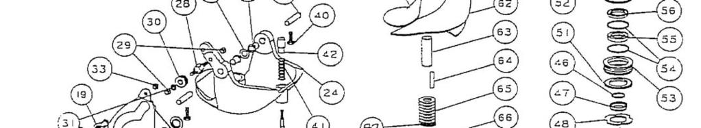
10 MODEL Z YAMAHA REF QTY PART DESCRIPTION REF QTY PART DESCRIPTION NO. NO SPONGE COLLAR Z SHIFT GUIDE SHAFT BEARING THRUST RING PUMP ADAPTER Z COLLAR BACKFIT WASHER SPRING LOCK 5/ THRUST WASHER BOLT HEX HD 5/16-18 X 2 1/ BEARING 7205B-UA BOLT HEX HD 5/16-18 X 2 3/ TRUARC ADAPTER PLATE Z SPACER DOWEL PIN 6 X 16 MM TRUARC N ZD WASHER SPRING LOCK M UPPER SEAL CARRIER W/SEALS & O RINGS BOLT HEX HD M X 35MM SPIROLOX RR-150S BOLT HEX HD M X 30MM SEAL INNER DOWEL PIN 3/16 X 1/ SEAL OUTER 6324-S BOLT HEX HD 3/8-16 X 1 1/ O RING /32X1 15/16X2 1/ VOLUTE WITH GATE Z BEARING CARRIER W/SEALS & O RINGS Z VOLUTE WITH EXHAUST TUBE Z O RING /16X5/16X7/ EXHAUST TUBE ASSY MED WASHER SPRING LOCK # CLIP EXHAUST TUBE FIL HD SLOTTED X 5/ NYLOC IMPELLER 5 7/8 W/36.1 SLEEVE HP WASHER FIBER 3/ IMPELLER 6 1/8 W/36.1 SLEEVE HP BOLT HEX HD 3/8-16 X 1/ IMPELLER 6 1/8 W/36.1 SLEEVE, STAINLESS BALL END 1/4X10-32 CABLE SHAFT SLEEVE PLASTIC MEDIUM LUBE HOSE ASSY IMPELLER TEE KEY - SQUARE ZIRC FITTING 1/ IMPELLER TEE KEY - 1/2 ROUND GREASE GUN SHIM WASHER MEDIUM GREASE 10 OZ TUBE 630-AA NUTKEEPER MED/PKG 2 PER BAG REVERSE GATE MEDIUM SHAFT NUT 5/8-18 BRASS NYLINER 3/8 1D X 1D X 11/ INTAKE ASSY 5 7/8 FLANGED W\ GRILL & LINER SPRING GATE PIVOT 3/ LINER 5 7/8 FLANGED PIN GATE PIVOT 3/8 MEDIUM INTAKE ASSY 6 1/8 FLANGED W\ GRILL & LINER SHAFT ROLLER LINER 6 1/8 FLANGED NYLOC 1/ STUD - INTAKE MEDIUM ROLLER ASSY NYLOC 1/ /4 WASHER AN960C INTAKE PAINTED ONLY MED FLANGED SHIFT CAM MEDIUM GRILL ROD NYLOC 1/ GRILL BAR MEDIUM BOLT HEX HD 1/4-20 X 3/4 171 BRACKET ASSY MORSE W/CLAMP & HARDWARE BUSHING CAM BRACKET CABLE SUPPORT WASHER CAM SHIM MORSE A SHIM-CAM CLAMP CHRYS CAM ECCENTRIC DRILLED FL JD SLOTTED X 5/ BOLT HEX HD 1/4-20 X 1 PATCH /4 WASHER AN960C BOLT HEX HD 1/4-20 X 3/4 PATCH BOLT HEX HD 1/4-20 X 5/ SPRING GATE BUMPER NYLOC GATE BUMPER TORSIONAL DAMPER 5/ FIL HD SLOT 10-32X 1 1/4 PATCH SHAFT ONLY, Z30S, 14T, 24-1/4 LG SHAFT ASSY COMPLETE,Z30S, 14T W/1275 KEY SHAFT ONLY, Z30L, 14T 29 LG SHAFT ASSY COMPLETE, Z30L, 14T W/1275 KEY SHAFT ONLY, ZS, 14T 24 5/8 LG. 911 SHAFT ASSY COMPLETE, ZS, 14T, W/1275 KEY SHAFT ONLY, ZL 14T, 29 7/16 LG. NOTE: FLUSH SCREW AND WASTER METRIC ON BLUE VOLUTES 915 SHAFT ASSY COMPLETE, ZL, 14T, W/1275 KEY WASHER FIBER M KEY, TEE WATER PUMP BOLT HEX HD M X 12 SIZE TORQUE 1/4-20 (M6) 8-9 FT-LBS 5/16-18 (M8) 12 FT-LBS 3/8-16 (M10) 22 FT-LBS TILLER STEERING: SHIFT ROD ASSY 1215, 1217, SEE PAGE 24 SHIFT CABLE ASSY 1261, 1262, SEE PAGE 27, Pg , SEE PAGE 28 BEARING SEAL SNAP & O RING KIT 803 1
11 SHIFFT ROD ASSEMBLY YAMAHA MODEL Z40M TILLER STEERING - CAM GATE 1215 SHORT 1217 LONG REF QTY PART NO. DESCRIPTION SHIFT ROD ZSM 18 7/8 SHORT SHIFT ROD U2L, V, ZLM, 23 1/8 LONG ROD END FORMED NUT HEX 1/ SPRING-ROD END /4 WASHER AN960C COTTER PIN 1/16 X 1/ SHIFT LEVER ZM FIL HD SLOTTED X FIL HD SLOTTED X 1 1/ NYLOC SPACER 5/16 ID X 1/ BOLT HEX HD 5/16-18 X KNOB 1 3/8
12 SHIFT CABLE ASSEMBLY YAMAHA MODEL Z30M TILLER STEERING 1261 SHORT 1262 LONG REF QTY PART NO. DESCRIPTION CABLE 3 FT MOR 33C SUPREME SHORT CABLE 3 1/2 FT MOR 33C SUPREME LONG BRACKET CABLE SUPPORT SHIM MORSE A CLAMP CHRYS FIL HD SLOTTED X 5/ /4 WASHER AN960C BOLT HEX HD 1/4-20 X 5/ NYLOC HEX NUT JAM CABLE ANCHOR MORSE FIL HD SLOTTED X NYLOC BALL JOINT MORSE SHIFT LEVER Z BOLT HEX HD 1/4-20 X BOLT HEX HD 1/4-20 X 1 1/ WASHER SPRING LOCK 1/ NUT HEX 1/ WASHER SPRING LOCK NO BALL END 1/4 X CABLE
13 SHIFT CABLE ASSEMBLY YAMAHA MODEL Z50, Y70, TILLER STEERING 1317 REF QTY PART NO. DESCRIPTION CABLE 3 1/2 FT MOR 33C SUPREME CLAMP CHRYS SHIM MORSE A FIL HD SLOTTED X 5/ NYLOC HEX NUT JAM BALL JOINT MORSE CABLE BLOCK Z Y TILLER BOLT HEX 1/4-20 X 3/ BALL END 1/4 X CABLE
MODEL BT SERIES ASSEMBLY INSTRUCTIONS FOR TOHATSU MSF40 AND MSF50 4 STROKE MOTORS HP 52.9 CU. IN. 3 CYLINDER STARTING 2014
 MODEL BT SERIES ASSEMBLY INSTRUCTIONS FOR TOHATSU MSF40 AND MSF50 4 STROKE MOTORS 40-50 HP 52.9 CU. IN. 3 CYLINDER STARTING 2014 1. Place the engine on the transom of your boat so that it is mounted vertically,
MODEL W SUZUKI SERIES ASSEMBLY INSTRUCTIONS HP, 1981 TO PRESENT
 MODEL W SUZUKI SERIES ASSEMBLY INSTRUCTIONS 115-140 HP, 1981 TO PRESENT 1. Temporarily clamp the engine on the transom of your boat or an engine stand so that the gearbox can be removed. 2. Disconnect
MODEL AF EVINRUDE / JOHNSON SERIES ASSEMBLY INSTRUCTIONS 2 CYLINDERS, CU. IN., STARTING 1989
 MODEL AF EVINRUDE / JOHNSON SERIES ASSEMBLY INSTRUCTIONS 2 CYLINDERS, 44.99 CU. IN., STARTING 1989 1. Place the engine on the transom of your boat so that it is mounted vertically, in the normal fashion.
MODEL M JOHNSON / EVINRUDE SERIES ASSEMBLY INSTRUCTIONS 4 CYLINDER, 1969 TO 1977
 MODEL M JOHNSON / EVINRUDE SERIES ASSEMBLY INSTRUCTIONS 4 CYLINDER, 1969 TO 1977 1. Place the engine on the transom of your boat so that it is mounted vertically, in the normal position. Remove the engine
MODEL BR SERIES ASSEMBLY INSTRUCTIONS MERCURY HP FOUR STROKE
 MODEL BR SERIES ASSEMBLY INSTRUCTIONS MERCURY 90-115HP FOUR STROKE 1. Place the engine on the transom of your boat so that it is mounted vertically, in the normal fashion. Remove the bolts holding the
MODEL A, H ASSEMBLY INSTRUCTIONS
 MODEL A, H ASSEMBLY INSTRUCTIONS 1. Place the engine on the transom of your boat so that it is mounted vertically, in the normal fashion. Open the access plate in the exhaust housing and disconnect the
OWNER S MANUAL SUPPLEMENT
 OWNER S MANUAL SUPPLEMENT Jet Drive Outboard BF60J / 40 Jet BF90J / 65 Jet Before operating your jet drive outboard for the first time, please read this Owner s Manual. Even if you have operated other
TILLER HANDLE KIT, P/N and INSTALLATION INSTRUCTION
 TILLER HANDLE KIT, P/N 5005579 and 5005777 INSTALLATION INSTRUCTION APPLICATION This kit is designed for use on 004 (SR) and newer Evinrude E-TEC 75 and 90 HP outboards. DO NOT install on any other models.
5/30/2014 F2.5MSH 0407 / TOP COWLING Yamaha Motor Corporation, U.S.A. All rights reserved.
 F.5MSH 0407 Page of 40 5/30/04 F.5MSH 0407 / TOP COWLING 04 Yamaha Motor Corporation, U.S.A. All rights reserved. F.5MSH 0407 Page of 40 5/30/04 Part List F.5MSH 0407 / TOP COWLING REF - NO PART NUMBER
file://c:\programdata\proquestms\partsmanagerpro\print\ ~13~11~5.html
 C60TLRZ 00 file://c:\programdata\proquestms\partsmanagerpro\print\8-9-0 ~~~5.html Page of 6 8/9/0 C60TLRZ 00 / TOP COWLING 0 Yamaha Motor Corporation, U.S.A. All rights reserved. C60TLRZ 00 file://c:\programdata\proquestms\partsmanagerpro\print\8-9-0
9/9/2014 F15MSHC 2004 / TOP COWLING Yamaha Motor Corporation, U.S.A. All rights reserved.
 F5MSHC 00 Page of 6 9/9/0 F5MSHC 00 / TOP COWLING 0 Yamaha Motor Corporation, U.S.A. All rights reserved. F5MSHC 00 Page of 6 9/9/0 Part List F5MSHC 00 / TOP COWLING REF - NO PART NUMBER PART NAME QUANTITY
9/8/ MSHZ 2001 / TOP COWLING Yamaha Motor Corporation, U.S.A. All rights reserved.
 9.9MSHZ 00 Page of 47 9/8/04 9.9MSHZ 00 / TOP COWLING 04 Yamaha Motor Corporation, U.S.A. All rights reserved. 9.9MSHZ 00 Page of 47 9/8/04 Part List 9.9MSHZ 00 / TOP COWLING REF - NO PART NUMBER PART
5/30/2014 F2.5LMHA 0313 / SCHEDULED SERVICE PARTS Yamaha Motor Corporation, U.S.A. All rights reserved.
 F.5LMHA 033 Page of 4 5/30/04 F.5LMHA 033 / SCHEDULED SERVICE PARTS 04 Yamaha Motor Corporation, U.S.A. All rights reserved. F.5LMHA 033 Page of 4 5/30/04 Part List F.5LMHA 033 / SCHEDULED SERVICE PARTS
9/7/2014 F9.9MSHV 1997 / CYLINDER CRANKCASE Yamaha Motor Corporation, U.S.A. All rights reserved.
 F9.9MSHV 997 Page of 45 9/7/04 F9.9MSHV 997 / CYLINDER CRANKCASE 04 Yamaha Motor Corporation, U.S.A. All rights reserved. F9.9MSHV 997 Page of 45 9/7/04 Part List F9.9MSHV 997 / CYLINDER CRANKCASE REF
9/7/2014 T9.9ELRZ 2001 / TOP COWLING Yamaha Motor Corporation, U.S.A. All rights reserved.
 T9.9ELRZ 00 Page of 56 9/7/0 T9.9ELRZ 00 / TOP COWLING 0 Yamaha Motor Corporation, U.S.A. All rights reserved. T9.9ELRZ 00 Page of 56 9/7/0 Part List T9.9ELRZ 00 / TOP COWLING REF - NO PART NUMBER PART
REF. NO. DESCRIPTION TOP COWLING 2 MOLDING, AIR DUCT 3 RIVET 4 SEAL 5 HOLDER, CLAMP BAND 6 BOLT, WITH WASHER 7 HOOK
 SUZHOU ALLPASS MACHINERY CO.,LTD Add:No.85,Jishui Road,Jinfeng Industrial Park,Mudu Town,Suzhou 215102,Jiangsu,P.R.China T15 SPARE PARTS EXPLODED DRAWING FIG. 1 1 TOP COWLING TOP COWLING 2 MOLDING, AIR
Magnesium Option, Late Model Front Seal, Viton, P/N 67256V Rear Seal, Viton, P/N 67257V Shifter Installed Heat Treated Yoke, P/N
 DESCRIPTION OPTION Magnesium Option, Late Model 80100L Front Seal, Viton, P/N 67256V 80109 Rear Seal, Viton, P/N 67257V 80110L Shifter Installed 80112L Heat Treated Yoke, P/N 62946-6 80119-6 Heat Treated
365L (2001) Page 1 of 36 54" Deck Assembly
 Page 1 of 36 54 Deck Assembly") 365L (2001) Page 1 of 36 54" Deck Assembly 365L (2001) Page 2 of 36 54" Deck Assembly 1 720-0241 1 S Wing Nut Knob 2 703-2817 1 Belt Cover LH 3 703-2816 1 Belt Cover RH 4 747-3306 1 Idler Spring Mounting
365L (2001) Page 1 of 36 54" Deck Assembly 365L (2001) Page 2 of 36 54" Deck Assembly 1 720-0241 1 S Wing Nut Knob 2 703-2817 1 Belt Cover LH 3 703-2816 1 Belt Cover RH 4 747-3306 1 Idler Spring Mounting
5/29/2014 3MSHY 2000 / CYLINDER CRANKCASE Yamaha Motor Corporation, U.S.A. All rights reserved.
 Page 1 of 22 3MSHY 2000 / CYLINDER CRANKCASE Page 2 of 22 Part List 3MSHY 2000 / CYLINDER CRANKCASE REF - NO PART NUMBER PART NAME QUANTITY REMARKS 1 6L5-W0090-01-1S CRANK CYLINDER ASSY 1 2 6L5-15100-00-1S
21A Tuffy Tiller Page 1 of 18 Bolo Tines & Wheels
 21A-510-081 Tuffy Tiller 12155 Page 1 of 18 Bolo Tines & Wheels 21A-510-081 Tuffy Tiller 12155 Page 2 of 18 Bolo Tines & Wheels Ref # Part Number Qty S/P/F Description 1 1100046 16 S Bolt-Hex Head, 3/8-16
1989 Jeep Cherokee. STEERING COLUMN' '1989 STEERING Jeep Steering Columns STEERING COLUMN STEERING Jeep Steering Columns
 STEERING COLUMN 1989 STEERING Jeep Steering Columns DESCRIPTION All models use collapsible steering columns. All columns have integral ignition switch and locking device. Optional tilt wheel is available
5/29/2014 3MSHU 1996 / CYLINDER CRANKCASE Yamaha Motor Corporation, U.S.A. All rights reserved.
 Page 1 of 22 3MSHU 1996 / CYLINDER CRANKCASE Page 2 of 22 Part List 3MSHU 1996 / CYLINDER CRANKCASE REF - NO PART NUMBER PART NAME QUANTITY REMARKS 1 6L5-W0090-01-4D CRANK CYLINDER ASSEMBLY 1 2 6L5-15100-00-94
Assembly Manual. 1/10th Formula 1 Car
 Assembly Manual 1/10th Formula 1 Car Center Pivot Bag 1 3374 - Center Pivot Socket 40194 - Hard Anodized Alum Pivot ball 3254-2-56 *Note - Sometimes it is helpful to slightly over-tighten the top clamp
B190 8 H.P. Lawn Vacuum (1995) Page 1 of 22 Chute Assembly
 Page 1 of 22 Chute Assembly") 245-315B190 8 H.P. Lawn Vacuum (1995) Page 1 of 22 Chute Assembly 245-315B190 8 H.P. Lawn Vacuum (1995) Page 2 of 22 Chute Assembly Ref # Part Number Qty S/P/F Description 1 681-0068 1 S CHUTE ASSEMBLY
245-315B190 8 H.P. Lawn Vacuum (1995) Page 1 of 22 Chute Assembly 245-315B190 8 H.P. Lawn Vacuum (1995) Page 2 of 22 Chute Assembly Ref # Part Number Qty S/P/F Description 1 681-0068 1 S CHUTE ASSEMBLY
INSTALLATION INSTRUCTIONS OUTBOARD JET PUMP SECONDARY SHIFT CABLE
 APPLICATION INSTALLATION INSTRUCTIONS OUTBOARD JET PUMP SECONDARY SHIFT CABLE This instruction sheet is intended to supplement the aftermarket jet pump manufacturer s installation instructions. Evinrude
Mfg. No: P216020KWV, 21" 6 TP Steel Deck Series
 Parts Manual Mfg. No: 7800557 P216020KWV, 21" 6 TP Steel Deck Series Copyright Briggs and Stratton. All Rights reserved 28-Sep-2018 Model Components Table Of Contents Page Accessory Recycling Kits..............................................................................
Chevy Nova Pro-Touring Front Suspension Installation Instructions
 1962-1967 Chevy Nova Pro-Touring Front Suspension Installation Instructions 1-800-984-6259 www.totalcostinvolved.com 1 Pro-Touring Clip A-Arm Assembly Sway Bar Assembly Fender Panel Kit 8 7/16-20 * 1 ¼
Step 4 Press the sleeve gear assembly through the center of the bearing plate assembly so that the gear and bearing are in contact.
 Rotational Center (ip-3009_page) : DATE: 0//207 QTY Parts Needed On This Page Tools Needed On This Page AM-303 40T Steer Gear, plated Arbor Press AM-0253 /2" ID, /2" Long Bushing 5/32 Allen Wrench AM-002
INSTALLATION INSTRUCTIONS 88029
 INSTALLATION INSTRUCTIONS 88029 FOR SUSPENSION SYSTEMS RS6503: JEEP WRANGLER (TJ) READ ALL INSTRUCTIONS THOROUGHLY FROM START TO FINISH BEFORE BEGINNING INSTALLATION REV F IMPORTANT NOTES! WARNING: This
HP Electric PTO Horse Tiller Page 1 of 23 Bolo Tine Assemblies
 12090-8HP Electric PTO Horse Tiller Page 1 of 23 Bolo Tine Assemblies 12090-8HP Electric PTO Horse Tiller Page 2 of 23 Bolo Tine Assemblies 1 1901975001 2 S Tine Holder-welded steel, fits left or right
RL-F60 PARTS LIST # I USE THIS PARTS LIST FOR: Hoist Serial Number 6745 to
 RL-F60 PARTS LIST # 102692I USE THIS PARTS LIST FOR: Hoist Serial Number 6745 to For older hoists use the following: Parts List No. 102692H for Serial Number 2640 to 6744 IF YOUR HOIST DOES NOT FALL WITHIN
Parts Manual Rev. A RZT48 /
 115 91 36-2 Rev. A Parts Manual RZT48 / 96 62001-00 Please read the operator manual carefully and make sure you understand the instructions before using the machine. Gasoline containing a maximum of 10%
DRIVE AXLE Volvo 960 DESCRIPTION & OPERATION AXLE IDENTIFICATION DRIVE AXLES Volvo Differentials & Axle Shafts
 DRIVE AXLE 1994 Volvo 960 1994 DRIVE AXLES Volvo Differentials & Axle Shafts 960 DESCRIPTION & OPERATION All 960 station wagon models use type 1041 rear axle assembly. All 960 4-door models use type 1045
PRO HYDRO WALK BEHIND MOWERS MID-SIZE SERIES 3
 Parts Manual for MID-SIZE SERIES 3 POWER UNIT MODELS SPLH153KW SPLH173KW MOWER MODELS SPA361 SPA481 SPA521 SPA611 McDonough, GA, 30253 U.S.A. COPYRIGHT 2005 SNAPPER PRODUCTS, INC. ALL RIGHTS RESERVED.
Max IV Rear Axle Replacement For models after Serial Number and all rear splined axle replacements.
 Max IV Rear Axle Replacement For models after Serial Number 19089 and all rear splined axle replacements. 10/8/03 Max IV Snap Ring Rear Axle replacement.doc Tools required: 9/16 Wrench 6 Extension Steel
4ACMH 04 (6E03) 5CMH 04 (6E33)
 5CMH 04 (6E33)") MH 04 (6E03) MH 04 (6E33) 1C6E0-700E1 ( 2C6E0-700E1 ) FOREWORD This Parts Catalogue is related to the parts for the model(s) on the cover page. When you are ordering replacement parts, please refer to
MH 04 (6E03) MH 04 (6E33) 1C6E0-700E1 ( 2C6E0-700E1 ) FOREWORD This Parts Catalogue is related to the parts for the model(s) on the cover page. When you are ordering replacement parts, please refer to
PARTS CATALOG ODYSSEY INCLUDES MOWER
 PARTS CATALOG 8-3350 ODYSSEY INCLUDES MOWER INDEX PAINT ENGINES GENERAL INFO PRODUCT IDENTIFICATION NUMBERS (P.I.N.) OR SERIAL NUMBERS (S/N) ENGINE MODEL, SERIAL AND SPECIFICATION NUMBERS TRACTOR MODEL
Sno-Thro. Parts Manual. Models ST624E A 8/10 Printed in USA
 Sno-Thro Parts Manual Models 920001 - ST62E 0199100A 8/10 Printed in USA THE MANUAL Before you operate your unit, carefully and completely read manuals supplied with the unit. The contents will provide
PARTS BOOK FLAIL HEADS 90 SIDE MID-MOUNT
 PARTS BOOK FLAIL HEADS 90 SIDE MID-MOUNT 5.0.8 DIAMOND MOWERS, LLC 350 E 60 th St. North Sioux Falls, SD 5704 FOR WARRANTY CALL DIAMOND MOWERS DIRECT: 888-960-0364 OUR TECHNICIANS WILL DIAGNOSE YOUR SITUATION
Chain Box and Knife. Item # Description Part Number 180-D & GS
 Chain Box and Knife Item # Description Part Number 180-D & GS 1 Groove pin 2275-03160 2 Hex cap screw 2175-03061 3 Washer 2275-03060 4 Setscrew 2175-07163 5 Chain box 4975-00355 6 Berkel logo 3175-00152
Models E640F, E660F, E6C0F & E660G
 Models E0F, E0F, EC0F & E0G 0 0 0 0 0-0 Lock Jam Nut /- -0 Flat Idler -B Auger Idler Arm 0-0A Hex Cap Screw /- x.0-0 Shoulder Screw -0 Flat Washer,. x. x.0-0 Extension Spring -0 Hex Nut /- -00 Hex Nut
GLACIER PRO RANGER MID SIZE MOUNT KIT
 GLACIER PRO RANGER MID SIZE MOUNT KIT P/N 2880261 APPLICATION FOR USE WITH THE GLACIER PRO MID SIZE PLOW SYSTEM (P/N 2880260) ON 2010 AND NEWER RANGER MID SIZE MODELS BEFORE YOU BEGIN Read these instructions
M-ZT 61. Parts Manual. Zero Turn Mower /
 Parts Manual M-ZT 61 Zero Turn Mower / 967177008-01 Please read the operator manual carefully and make sure you understand the instructions before using the machine. When you need spare parts or support
FORD F150 / BRONCO 4X4
 MAY 2,1995 1987-1991 FORD F150 / BRONCO 4X4 ATTACHMENT KIT PARTS LIST ITEM STOCK DESCRIPTION QTY. ITEM STOCK DESCRIPTION QTY. MOUNTING CARTON 1 815000 169 MOUNTING FRAME 1 2 815000 171 PUSHARM DRIVERS
MODEL NO REPAIR PARTS FRAME
 FRAME 37 FRAME Key No. Part No. Description 90 198573X479 COVER, BOTTOM 91 198574 SCREW, 1/4--20X.63 103 406364X008 IDLER ASSEMBLY, AUGER 105 198576 PIN, HAIR.38DIAX1.64LG 106 198580 PIN, CLEVIS 3/16 DIA
EUROPEAN REAR ENGINE RIDER SERIES 20
 Parts Manual for EUROPEAN REAR ENGINE RIDER SERIES 20 MODEL E281320BE E331520KVE McDonough, GA, 30253 U.S.A. Briggs & Startton Yard Power Products Group Copyright 2006 Briggs & Startton Corporation Milwaukee,
INSTRUCTIONS. Disassembly. Shifter Cam Assembly. Shifter Forks
 INSTRUCTIONS Disassembly To protect against accidental start-up of vehicle, always disconnect the negative battery cable before working on the motorcycle. Failure to disconnect the battery cable could
J115MLCNB 1982 : CARBURETOR [1/18] Page 1 of 43
![J115MLCNB 1982 : CARBURETOR [1/18] Page 1 of 43](/thumbs/94/118301039.jpg "J115MLCNB 1982 : CARBURETOR [1/18] Page 1 of 43") J115MLCNB 1982 : CARBURETOR [1/18] Page 1 of 43 J115MLCNB 1982 : CARBURETOR [1/18] 0392596 0392596 1 CARB ASSY., Upper, 90 0392597 0392597 1 CARB ASSY., Lower, 90 0392600 0392600 1 CARB ASSY., Upper, 115
J115MLCNB 1982 : CARBURETOR [1/18] Page 1 of 43 J115MLCNB 1982 : CARBURETOR [1/18] 0392596 0392596 1 CARB ASSY., Upper, 90 0392597 0392597 1 CARB ASSY., Lower, 90 0392600 0392600 1 CARB ASSY., Upper, 115
Sno-Thro. Parts Manual. Models ST8524E ST724E ST5524E ST ST ST7524
 Sno-Thro Parts Manual Models 93204 - ST24E 932046 - ST724E 932047 - ST24E 93204 - ST20 9323 - ST20 932312 - ST724 006600A /06 Printed in USA THE MANUAL Before you operate your unit, carefully and completely
S/N 880, ,000 Page 1 of 84 Air Cleaner
 1641 S/N 880,001-899,000 Page 1 of 84 Air Cleaner 1641 S/N 880,001-899,000 Page 2 of 84 Air Cleaner 1 BS-805406 2 S Screw, Sems 2 BS-805655 1 S Gasket, Air Cleaner 3 BS-807796 1 S Bracket, Air Cleaner
E70PL4EEC 1999 : CAMSHAFT [1/23] Page 1 of 49
![E70PL4EEC 1999 : CAMSHAFT [1/23] Page 1 of 49](/thumbs/96/129257940.jpg "E70PL4EEC 1999 : CAMSHAFT [1/23] Page 1 of 49") E70PL4EEC 1999 : CAMSHAFT [1/23] Page 1 of 49 E70PL4EEC 1999 : CAMSHAFT [1/23] 1 5030657 1 CAMSHAFT 2 5030658 1 PLATE, Camshaft thrust 3 5030549 1 SEAL, Camshaft 4 5030989 2 BOLT, Plate 5 5030663 8 ARM,
E70PL4EEC 1999 : CAMSHAFT [1/23] Page 1 of 49 E70PL4EEC 1999 : CAMSHAFT [1/23] 1 5030657 1 CAMSHAFT 2 5030658 1 PLATE, Camshaft thrust 3 5030549 1 SEAL, Camshaft 4 5030989 2 BOLT, Plate 5 5030663 8 ARM,
CLUTCH. Section IV DATA AND SPECIFICATIONS CHRYSLER SERVICE MANUAL. Page. Clutch Pedal Adjustment 74. Clutch Disassembly 77. Clutch Assembly 78
 CLUTCH 73 Section IV CLUTCH Page Clutch Pedal Adjustment 74 Clutch Disassembly 77 Clutch Assembly 78 Service Diagnosis 81 DATA AND SPECIFICATIONS MODEL TYPE 1376 (Borg-Beck) Single Plate, Dry Disc FACINGS
CHEVROLET/GMC K K K3500 4X BLAZER/JIMMY 4X ATTACHMENT KIT
 6-203 August, 2003 1988-1999 CHEVROLET/GMC K1500 - K2500 - K3500 4X4 1992-1994 BLAZER/JIMMY 4X4 81001 ATTACHMENT KIT PARTS LIST ITEM STOCK DESCRIPTION QTY. ITEM STOCK DESCRIPTION QTY. 81001 MOUNTING CARTON
DRIVE_UNIT_ / TRANSOM PLATE
 DRIVE_UNIT_989 989 / TRANSOM PLATE Part List DRIVE_UNIT_989 989 / TRANSOM PLATE REF - NO PART NUMBER PART NAME QUANTITY REMARKS 6T4-4583-00-EK PLATE, TRANSOM 2 6T4-09-00-00 MOUNT, RUBBER 2 2 3 6T4-029-00-00
136R616G190 Lawn Tractor FST-16 (1996) Page 1 of 27 42" Mowing Deck
 Page 1 of 27 42 Mowing Deck") 136R616G190 Lawn Tractor FST-16 (1996) Page 1 of 27 42" Mowing Deck 136R616G190 Lawn Tractor FST-16 (1996) Page 2 of 27 42" Mowing Deck 3 97600A 1 S 42" Deck Ass'y. Code: N notates a new part (not previously
136R616G190 Lawn Tractor FST-16 (1996) Page 1 of 27 42" Mowing Deck 136R616G190 Lawn Tractor FST-16 (1996) Page 2 of 27 42" Mowing Deck 3 97600A 1 S 42" Deck Ass'y. Code: N notates a new part (not previously
RAS-5E PART NO Date: 04/08/02
 33-400, 33-401, 33-402, 33-403 14 RADIAL SAWS 33-410, 33-411, 33-412, 33-413 16 RADIAL SAWS 33-420, 33-421, 33-422, 33-423 18 RADIAL SAWS RAS-5E PART NO. 424-03-651-0018 Date: 04/08/02 Page1/ RAS-5E /DEB
Models 642E, 642F, 662E, 644E, 664F, & 6A4E
 Models E, F, E, E, F, & AE 0 0 0 0 Models E, F, E, E, F, & AE. -0 Lock Jam Nut /-. -0 Flat Idler. -B Auger Idler Arm. 0-0A Hex Cap Screw /- x.0. -0 Bushing. -0 Bell Washer. -00 Hex Nut /-. -0 Hex Lock
Parts Manual Rev. B RZT48 /
 115 91 36-2 Rev. B Parts Manual RZT48 / 96 62001-00 Please read the operator manual carefully and make sure you understand the instructions before using the machine. Gasoline containing a maximum of 10%
PIÈCES DÉTACHÉES ELT125D33 1KV. Tondeuse autoportée
 PIÈCES DÉTACHÉES Tondeuse autoportée ELT15D33 1KV Yvan Béal - 1, av. de l Agriculture - B.P. 16 Z.I. du Brézet - 63014 Clermont-Ferrand Cedex Tél : 04 73 91 93 51 - Télécopie : 04 73 90 3 11 www.yvanbeal.fr
CHEVROLET/GMC K10 - K20 - K BLAZER/JIMMY/SUBURBAN/CREWCAB CAB CHASSIS 4X ATTACHMENT KIT
 1973-1987 CHEVROLET/GMC K10 - K20 - K30 1973-1991 BLAZER/JIMMY/SUBURBAN/CREWCAB CAB CHASSIS 4X4 ATTACHMENT KIT PARTS LIST ITEM STOCK DESCRIPTION QTY. ITEM STOCK DESCRIPTION QTY. MOUNTING CARTON 1 815000
G190 LT-145 (1992) Page 1 of 27 42" Mower Deck
 Page 1 of 27 42 Mower Deck") 132-736G190 LT-145 (1992) Page 1 of 27 42" Mower Deck 132-736G190 LT-145 (1992) Page 2 of 27 42" Mower Deck 3 17600A 1 S 42" Deck Ass'y. Code: N notates a new part (not previously existing). 813-06119
132-736G190 LT-145 (1992) Page 1 of 27 42" Mower Deck 132-736G190 LT-145 (1992) Page 2 of 27 42" Mower Deck 3 17600A 1 S 42" Deck Ass'y. Code: N notates a new part (not previously existing). 813-06119
MZ 52LE. Parts Manual. Zero Turn Mower /
 Parts Manual MZ 52LE Zero Turn Mower / 9677406-00 Please read the operator manual carefully and make sure you understand the instructions before using the machine. When you need spare parts or support
Pony V Page 1 of 24 Battery Mounting Bracket
 5151 Pony V Page 1 of 24 Battery Mounting Bracket 5151 Pony V Page 2 of 24 Battery Mounting Bracket 2 9296 2 CABLE- battery (replaces #9223) 4 9224 1 CLIP- vent tube shield (small) 6 9826 2 NUT- hex, 5/16"-24
40VEO 03(63C2) 50HETO 03(62X4) 50HEDO 03(62X5) 50HMHO 03(63G2) 1B62X 664E1
 50HETO 03(62X4) 50HEDO 03(62X5) 50HMHO 03(63G2) 1B62X 664E1") 40V 03(63C2) 50H 03(62X4) 50H 03(62X5) 50H 03(63G2) 1B62X 664E1 FOREWORD This Parts Catalogue is related to the parts for the model(s) in the below frame. When you are ordering replacement parts, please
40V 03(63C2) 50H 03(62X4) 50H 03(62X5) 50H 03(63G2) 1B62X 664E1 FOREWORD This Parts Catalogue is related to the parts for the model(s) in the below frame. When you are ordering replacement parts, please
Continuous Sampling OVERSHOT STYLE ROD STYLE SWIVEL OVERSHOT ASSEMBLY CONNECTING ROD NWJ J SERIES LATCH HOUSING LATCH ASSEMBLY BEARING ASSEMBLY
 ROD STYLE OVERSHOT STYLE OVERSHOT ASSEMBLY SWIVEL CONNECTING ROD NWJ J SERIES LATCH HOUSING LATCH ASSEMBLY BEARING ASSEMBLY SAMPLE BARREL SPLIT OR SOLID SHOE Split Barrel Sampler Assemblies Continuous
INSTALLATION INSTRUCTION 88148
 INSTALLATION INSTRUCTION 88148 Rev C For Rancho Suspension Systems RS6548, RS6549 & RS6550: GM 2500HD, 2500, and 1500HD Trucks READ ALL INSTRUCTIONS THOROUGHLY FROM START TO FINISH BEFORE BEGINNING INSTALLATION
CYLINDER HEAD CONTINUED ON NEXT FRAME. Ref. Part No. Number Description Qty Remarks
 A1 CYLINDER HEAD 1 4JY-11111-00-00 HEAD, CYLINDER 1 (4JY-11111-01-00).......... 1 2 90116-08394-00 BOLT, STUD.............. 5 3 90176-08026-00 NUT, CROWN............. 5 4 90201-08087-00 WASHER, PLATE...........
MK-5000G exploded VieW
 Frame accessories 38 cutting head Pump Assembly 39 connecting linkage foot pedal linkage 40 curtain blade guard 41 ENGINE Assembly 42 PARTS LIST A Frames - - A1 Frame, MK-5000 Main 1 155541 B Pivot Bracket
Guardmatic Masonry / Refractory Saw Gasoline Model Parts List
 October 23, 2003 d Guardmatic Masonry / Refractory Saw Gasoline Model Parts List 542201008 Reference Information: Model No.: Serial No.: Date Purchased: NOTES: DECAL DESCRIPTIONS AND LOCATIONS DESCRIPCIÓN
2008, K&M NEWSPAPER SERVICES, INC. INSERTER 2299 INSERTER
 99 INSERTER - - - 800-88-0 COMPLETE FIXED POCKET WALL ITEM PART # DESCRIPTION QUANTITY KMS 0CW COMPLETE POCKET WALL COMES ASSEMBLED WITH YOUR CHOICE OF GRIPPERS & PADDLES - - - 800-88-0 FIXED POCKET WALL
21" STEEL DECK WALK BEHIND MOWER "MR" SERIES 17
 Parts Manual for "MR" SERIES 17 PUSH MODELS MR216017B MR216017BV MRP216517B WMR216017B WMR216017BV WMR216517B PROPELLED MODELS MRP216017B MRP216017BV MRP216517B WMRP216017B WMRP216517B EMRP216017B EMRP216517B
Champion Series Zero-Turn Riders & Mower Decks
 Parts Manual Champion Series Zero-Turn Riders & Mower Decks HP Tractors Mfg. No. Description Champion, HP Zero-Turn Rider Champion, HP Zero-Turn Rider (CE) 0HP Tractors Mfg. No. Description Champion, 0HP
Champion Reverse Gear Harley-Davidson Six Speed Transmissions for FLH 2007 to 2008 and Softail 2007 up
 Champion Reverse Gear s for FLH 2007 to 2008 and Softail 2007 up (Cable or Hydraulic Clutch) Installation Instructions Revision 11 Champion Motorcycle Accessories International, Inc. dba Champion Sidecars
Parts Catalog SLICING MACHINES
 Parts Catalog Model 4600P SLICING MACHINES MODELS: 4600P, 4975P & 493 05-0-2 IMPORTANT! TO EXPEDITE SHIPMENT OF PARTS, ALWAYS SPECIFY MODEL, REV, PART NUMBER, AND SERIAL NUMBER OF SLICER. GLOBE FOOD EQUIPMENT
Classic12 Belt Sander
 Classic12 Belt Sander Section II Parts and Service Manual AMERICAN SANDERS TECHNOLOGY Classic 12 Belt Sander Operator's Manual Page 21 Assembly Drawing #1 11/00 7 8 9 12 13 11 1 10 85 14 6 81 80 79 76
TRANSMISSION PARTS BOOK
 TRANSMISSION PARTS BOOK SS-6, SS-636, SS-836 SS-8, SS-08 DATE: 7-3-96 CLARK 8000 SERIES INTERMEDIATE DROP BARAGA PRODUCTS, INC. 55 N. Superior Ave. Baraga, MI 9908-08 Ph. (906) 353-6675 Fax (906) 353-75J
21Inch Heavy-Duty Recycler Rear Bagger Lawn Mower
 Form Number 3357-387 Rev B 21Inch Heavy-Duty Recycler Rear Bagger Lawn Mower Model No. 22188-270000001 and up. Parts Catalog Ordering Replacement Parts To order replacement parts, please supply the part
CLUTCH CONTENTS SERVICE DIAGNOSIS. (a) Worn or damaged disc assembly. (b) Grease or oil on disc facings. (c) Improperly adjusted cover assembly.
 Worn or damaged disc assembly. (b) Grease or oil on disc facings. (c) Improperly adjusted cover assembly.") CLUTCH CONTENTS -GROUP 6 Page CLUTCH HOUSING ALIGNMENT... 6 CLUTCH PEDAL FREE PLAY 1 CLUTCH RELEASE BEARING 5 CLUTCH RELEASE FORK... 5 CLUTCH SERVICING 2 PILOT BUSHING CRANKSHAFT TO TRANSMISSION DRIVE
CLUTCH CONTENTS -GROUP 6 Page CLUTCH HOUSING ALIGNMENT... 6 CLUTCH PEDAL FREE PLAY 1 CLUTCH RELEASE BEARING 5 CLUTCH RELEASE FORK... 5 CLUTCH SERVICING 2 PILOT BUSHING CRANKSHAFT TO TRANSMISSION DRIVE
2. With the rear door open remove pull-style clip from the passenger side just below the door latch.
 LoD Offroad FJ Cruiser Rear Bumper with Tire Carrier Installation Instructions 1. Begin with removing factory spare from the rear door. 2. With the rear door open remove pull-style clip from the passenger
IMCO SCX SERIES INFORMATION, OPERATION & MAINTAINANCE
 IMCO SCX SERIES INFORMATION, OPERATION & MAINTAINANCE Warning! Warning! Warning! Danger! Warning! 1. SCX & SCX4 Drives will not fit on a standard gimbal helmet, IMCO HELMET: #05-8025 Black or #05-8027
CYLINDER HEAD CONTINUED ON NEXT FRAME. Ref. Part No. Number Description Qty Remarks
 A1 CYLINDER HEAD 1 4JY-11111-00-00 HEAD, CYLINDER 1 (4JY-11111-01-00).......... 1 2 90116-08394-00 BOLT, STUD.............. 5 3 90176-08026-00 NUT, CROWN............. 5 4 90201-08087-00 WASHER, PLATE...........
SECTION 7: PARTS LIST FOR MODEL 5KL
 SECTION 7: PARTS LIST FOR MODEL 5KL 3 9 4 5 6 7 0 4 3 5 3 34 9 8 5 6 7 8 3 30 3 4 5 0 9 8 6 7 5 7 68 40 5 5 7 39 36 53 60 58 54 57 58 59 48 50 49 45 46 4 44 4 6 35 6 65 63 64 66 67 47 0 Model 5KL. 73-0447A
Loader Backhoe Front Axle Parts 2WD & 4WD
 Loader Backhoe Front Axle Parts 2WD & 4WD SECTION G LOADER BACKHOE FRONT AXLE PARTS CASE 2WD AXLE PARTS G2 - G5 CARRARO APPLICATIONS G6 - G25 FRONT AXLE KITS G23 - G25 CASE POWER STEERING VALVES & PUMPS
IRS-151 INSTALLATION INSTRUCTIONS `55-57 CHEVY INDEPENDENT REAR SUSPENSION
 IRS-151 INSTALLATION INSTRUCTIONS `55-57 CHEVY INDEPENDENT REAR SUSPENSION Please read these instructions completely before starting your installation. Remember the basic rule for a successful installation:
INSTALLATION AND PARTS MANUAL
 INSTALLATION AND PARTS MANUAL FOR JOHN DEERE PS TRACTORS NOTE: This manual covers mounting and control group installation, and parts specific to this winch on the specified tractor. For all other winch
WJ JACUZZI ENERGIZER PARTS LIST
 WJ JACUZZI ENERGIZER PARTS LIST BAG KIT QTY PART # DESCRIPTION ITEM CK. 1 B-1007 THRUST BEARING 8 F20LW LOCKWASHER, 5/16 8 F21CS HEX HEAD CAP SCREW, 5/16-18 X 1-1/4 1 K-4007 SHIM KIT W / 3 EXTRA.060 SHIMS
INSTALLATION GUIDE Bolt-On Drag-Race Strut Clip Chevy II
 INSTALLATION GUIDE 7702 Bolt-On Drag-Race Strut Clip 1962-67 Chevy II Description: STRUT CLIP 4130 BOLT ON 62-67 CHEVY II, INCLUDES 4130 ROUND TUBE FRAME CLIP, DOUBLE-ADJUSTABLE STRUTS, ADJUSTABLE-HEIGHT
62ZB. 62 BEAST Zero Turn Riding Mower. Kawasaki FX850V Engine
 62ZB 62 BEAST Zero Turn Riding Mower Kawasaki FX850V Engine 62ZB Deck Parts Diagram Key Item # Gxi Part Number Description 1 SP11-000063 Belt guard, 62ZB, set of 2 with rubber T-handle receivers 2 SP12-000229
RL-G70 PARTS LIST # I USE THIS PARTS LIST FOR: Hoist Serial Number 6597 to
 RL-G70 PARTS LIST # 102693I USE THIS PARTS LIST FOR: Hoist Serial Number 6597 to For older hoists use the following: Parts List No. 102692H for Serial Number 2485 to 6596 IF YOUR HOIST DOES NOT FALL WITHIN
1984 Dodge W250 PICKUP
 1984 Dodge W250 PICKUP Submodel: Engine Type: V8 Liters: 5.2 Fuel Delivery: CARB Fuel: GAS Dana 44 MODELS THROUGH 1984 2. Raise and safely support the vehicle, then remove the wheel hub and bearings as
STEERING SYSTEM 6 A POWER STEERING
 STEERING SYSTEM 6 A 22147 POWER STEERING Table of Contents Page Specifications............................ 6A-1 Torque Specification................... 6A-1 Special Tools............................ 6A-1
Parts Manual for PRO GEAR EXPRESS MID-SIZE WALK BEHIND MOWERS SERIES 0 & 1 POWER UNIT MODELS MOWER MODELS SPE140KW SPE151KW SPEL150KH
 Parts Manual for MID-SIZE WALK BEHIND MOWERS SERIES 0 & 1 POWER UNIT MODELS SPE1250KW SPE131KW SPE140KW SPE150KH SPE151KW SPEL150KH MOWER MODELS SPE360 SPE361 SPE481 McDonough, GA, 30253 U.S.A. COPYRIGHT
9.9MHC (63V3) 15MHC (63W3) 9.9FMH 04 (63V3) 15FMH 04 (63W3)
 15MHC (63W3) 9.9FMH 04 (63V3) 15FMH 04 (63W3)") 9.9MHC (63V3) 15MHC (63W3) 9.9FMH 04 (63V3) MH 04 (63W3) 1C63V-100E1 ( 2C63V-100E1 ) FOREWORD This Parts Catalogue is related to the parts for the model(s) on the cover page. When you are ordering replacement
9.9MHC (63V3) 15MHC (63W3) 9.9FMH 04 (63V3) MH 04 (63W3) 1C63V-100E1 ( 2C63V-100E1 ) FOREWORD This Parts Catalogue is related to the parts for the model(s) on the cover page. When you are ordering replacement
21" STEEL DECK WALK BEHIND MOWER "MR" SERIES 17
 Parts Manual for 21" STEEL DECK WALK BEHIND MOWER "MR" SERIES 17 PUSH MODELS MR216017B MR216017BV WMR216017B WMR216017BV WMR216517B PROPELLED MODELS MRP216017B MRP216017BV MRP216517B WMRP216017B WMRP216517B
Parts Manual MZ5225 /
 Gasoline containing up to 10% ethanol (E10) is acceptable for use in this machine. The use of any gasoline exceeding 10% ethanol (E10) will void the product warranty. Parts Manual MZ5225 / 966690502 Please
CP-1, CP-2, CP-2L & CPD-2 Series Overhaul
 Replacement of Mechanical Seals for CM, CMU, CS and CSU Series Pumps Installation Instructions Form No. F-1031 Section 5013 Issue Date 03/01/85 Rev. Date 02/08/11 CP-1, CP-2, CP-2L & CPD-2 Series Overhaul
STEERING COLUMN - TILT
 STEERING COLUMN - TILT 1994 Toyota Celica 1994 STEERING Toyota - Steering Column - Tilt Wheel Celica DESCRIPTION & OPERATION Tilt steering wheels incorporate a mainshaft, attached by a "U" joint to an
Service Parts. Doosan 11.1 L. Engine. Engine Model: Generator Models: 180/200REZX 180/200RZX TP /09
 Service Parts Engine Engine Model: Doosan. L Generator Models: 80/00REZX 80/00RZX TP-0 /09 Table of Contents Introduction... Numbering System Significance... Illustrations... How to Find Part Numbers...
PARTS LIST WRANGLER 2625 DB
 PARTS LIST WRANGLER 2625 DB 1 NOTES 2 BRUSH GEAR MOTOR ITEM PART NO. PART DESCRIPTION QTY. 2393501 COMPLETE MOTOR ASSEMBLY 1 101 3391221 NEGATIVE LEAD 1 102 3391201 1/4-20 X 7 3/4THRU BOLT 2 103 10-24
Parts Manual MZ52 /
 Gasoline containing up to 10% ethanol (E10) is acceptable for use in this machine. The use of any gasoline exceeding 10% ethanol (E10) will void the product warranty. Parts Manual MZ52 / 962401 Please