TRANSMISSION SPECIFICS VALVE BODY COMPONENTS
|
|
|
- Meryl Morgan
- 5 years ago
- Views:
Transcription
1 TRANSMISSION SPECIFICS VALVE BODY COMPONENTS Valve body electrical components consist of: Pressure Regulator solenoids (EDS). Controlled by a Pulse Width Modulated (PWM) control signal from the TCM provides an adjustable positioning of the valve. The variable position makes these valves suitable for varying control pressures. Pressure Regulator valves are used for: Maintaining operating pressures Gradual TC Clutch lock up control Overlap shift control (system specific) Band Brake Activation (system specific) Magnetic Valve (Shift) Solenoids (MV). Controlled by a switched (on/off) power or ground signal from the TCM. The valves have two positions open or closed. Some are normally open and close when activated and some are normally closed and open when activated. MV solenoids are for: Controlling shift valve position ON/OFF control of TC lock up clutch Reverse Lock Out protection (early systems) Band Brake Activation (system specific) Shift lock control Input (Turbine) and output Speed Sensors. Analog inductive sensors that produce an A/C sine wave similar to an ABS/ASC wheel speed sensor. The signal frequency is proportional to the rotation speed of the monitored component. The speed sensors are used to monitor clutch slip for plausibility and shift points as well as maintaining adaptive hydraulic pressures. Transmission Oil Temperature Sensor: NTC resistor provides a variable voltage drop proportional to transmission oil temperature. For most systems, the NTC is soldered into the oil temp circuit of the wiring harness located in the transmission oil sump. The A5S 360R transmission contains a replaceable NTC plug in resistor probe that is clipped to a bracket and immersed in oil in the sump. These components are monitored statically and dynamically by the TCM and will set specific fault codes if the sensor or it s circuit becomes impaired. However, the components and their circuits to the TCM can be simultaneously checked during diagnosis. The following pages provide specific locations of the components within the transmissions.
 control and direct the powerflow through the")

2 TRANSMISSION POWERFLOW The TCM controls the hydraulic valve body by activating specific electrical solenoids and pressure regulators. The component locations within a transmission in relation to activation of shift components (multi plate clutches and brakes, band brakes, freewheels) control and direct the powerflow through the planetary gearset(s) providing various output ratios. By design, each transmission manages powerflow uniquely with a common goal of providing progressive output ratios. Visual explanation of a Planetary Gear Set power flow schematics At first glance the representation of a transmissions internal components is confusing. Understanding the powerflow through the transmission is explained by a powerflow schematic. Powerflow schematics are simple line drawings of the upper half of the transmission showing engine drive torque input, torque converter powerflow, clutches, brakes freewheels and the planetary gearset(s) to output. The illustrations below will help in understanding the schematics. 4HP 24 E9


3 Specifications for MV solenoids: 20 C temperature MV1 = 25 to 46Ω MV2 = 25 to 46Ω MV3 = Converter Lock-up Solenoid 25 to 46Ω MV5 = Pressure Regulator Solenoid 5 to 10Ω 4HP 24 E9 Cut Away View
4 A5S 310/270R VALVE BODY COMPONENTS MAIN PRESSURE REGULATOR Ohms 20 C +/- 5 C Ohms 80 C +/- 5 C SHIFT SOLENOIDS: MV 1 & MV Ohms 20 C +/- 5 C Ohms 80 C +/- 5 C BAND BRAKE REGULATOR Ohms 20 C +/- 5 C Ohms 80 C +/- 5 C


5 A4S 310/270R - POWER FLOW SCHEMATIC
(readings at +/- 7%) 20 C = 10Ω 90 C = 12.")
6 A5S 360R (GM 5) VALVE BODY COMPONENTS MAIN PRESSURE REGULATOR (temperature will affect resistances)(readings at +/- 7%) 20 C = 4Ω 90 C = 5.2Ω TORQUE CONVERTER REGULATOR TCC (temperature will affect resistances)(readings at +/- 7%) 20 C = 10Ω 90 C = 12.7Ω NTC TEMP SENSOR -30 C = 52594Ω 100 C = 178Ω SHIFT SOLENOIDS: A - B - C 20 C = 16Ω 70 = 19.1Ω SPEED SENSORS 20 C = 405Ω Note! Above resistance may vary as much as 15%


7 A5S 360R (GM 5) Powerflow Schematics: Planetary Gearset Input - Reaction - Output Chart


8 A5S 310Z VALVE BODY COMPONENTS

9 A5S 310Z Valve Body Resistance Nominal Values: 20 C Output Speed Sensor = 325Ω - +/- 40Ω Input Speed Sensor = 325Ω - +/- 40Ω NTC Sensor: 0 C 20 C 40 C 60 C EDS1 = 5.9Ω - +/- 5Ω MV1 = 28Ω MV2 = 28Ω MV3 = 28Ω MV4 = 28Ω MV5 = 28Ω MV6 = 28Ω Above MV Solenoid resistance values may vary up to 2Ω, dependant on temperatures!


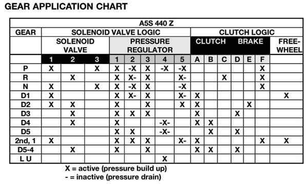
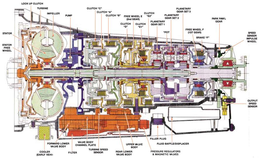
10 A5S 440Z VALVE BODY COMPONENTS

11 A5S 440Z - POWER FLOW SCHEMATIC

12


13 A5S 560Z VALVE BODY COMPONENTS


14 A5S 560Z - POWER FLOW SCHEMATIC
15
Shift Solenoid B (SSB) and Shift Solenoid D (SSD) Inverse Proportional VFS 2761
 and Shift Solenoid D (SSD) Inverse Proportional VFS 2761") Item Description 1 Shift Solenoid A (SSA) Variable Force Solenoid (VFS) 2 Shift Solenoid C (SSC) VFS SSB and SSD use inverse proportional operation. As the current from the PCM decreases, the pressure
Item Description 1 Shift Solenoid A (SSA) Variable Force Solenoid (VFS) 2 Shift Solenoid C (SSC) VFS SSB and SSD use inverse proportional operation. As the current from the PCM decreases, the pressure
LX AUTOMATIC TRANSMISSION NAG1 - SERVICE INFORMATION TABLE OF CONTENTS
 LX AUTOMATIC TRANSMISSION NAG1 - SERVICE INFORMATION 21-495 AUTOMATIC TRANSMISSION NAG1 - SERVICE INFORMATION TABLE OF CONTENTS page AUTOMATIC TRANSMISSION NAG1 - SERVICE INFORMATION DESCRIPTION...496
OPERATION FIRST GEAR POWERFLOW TJ - JEEP WRANGLER - 4.0L 6 CYL (MPI) 21 - Transmission and Transfer Case/Automatic - 42RLE/Operation
 21 - Transmission and Transfer Case/Automatic - 42RLE/Operation") 2006 - TJ - JEEP WRANGLER - 4.0L 6 CYL (MPI) 21 - Transmission and Transfer Case/Automatic - 42RLE/Operation OPERATION The 42RLE transmission ratios are: GEAR RATIO First 2.84 : 1 Second 1.57 : 1 Third
2006 - TJ - JEEP WRANGLER - 4.0L 6 CYL (MPI) 21 - Transmission and Transfer Case/Automatic - 42RLE/Operation OPERATION The 42RLE transmission ratios are: GEAR RATIO First 2.84 : 1 Second 1.57 : 1 Third
P0743-TCC SOLENOID CIRCUIT
 - KA - DODGE NITRO -.L V SOHC P-TCC SOLENOID CIRCUIT SOLENOID SUPPLY VOLTAGE MODULATION PRESSURE - - SHIFT PRESSURE TCC -/-5 C C C 5 C C C C T YL T YL/TN T T T T5 T YL/LG YL/BR YL/LB C T T T T T T5 T YL
12.Electrohydraulic Control System
 W1860BE.book Page 67 Tuesday, January 28, 2003 11:01 PM 12.Electrohydraulic Control System A: DESCRIPTION The electrohydraulic system for the transmission and transfer consists of various sensors and switches,
P0743-TCC SOLENOID CIRCUIT
 - XK - JEEP COMMANDER -.L MAGNUM V P-TCC CIRCUIT RUN-START F JUNCTION BLOCK FUSE A ELECTRO RELAY- - - SHIFT TCC -/ -5 SUPPLY VOLTAGE MODULATION HYDRAULIC UNIT (.L/DIESEL) T T T T5 T T T 5 A /LG DG/ C Z
P0750-LR SOLENOID CIRCUIT
 2008 Dodge Pickup 4.7L Eng R1500 P0750-LR SOLENOID CIRCUIT Circuit Schematic Fig 1: Transmission Solenoid/TRS Assembly Circuit Schematic Courtesy of CHRYSLER LLC Additional Wiring For complete wiring diagrams
ZF4HP16. Technical Bulletin # Signal Combination L1 L2 L3 L4 P R N D
 Transmission: Subject: Application: Issue Date: Technical Bulletin # 1308 ZF4HP16 Electronical Components Description 2005 Suzuki Forenza L4-2.0L February, 2010 ZF4HP16 Electronical Components Description
DTC P0743 sets when the TCM detects an open circuit, a short to power, or a short to ground in the TCC PWM solenoid circuit for 1.5 seconds.
 Page 1 of 5 2005 GMC Truck GMC K Sierra - 4WD Sierra, Silverado VIN C/K Service Manual Document ID: 1492351 DTC P0743 Circuit Description The torque converter clutch (TCC) solenoid is a pulse width modulated
1 of 9 5/29/2014 6:01 AM
 1 of 9 5/29/2014 6:01 AM Torque Converter Clutch Pulse Width Modulation (TCC PWM) Solenoid, TCC Solenoid, and Wiring Harness Tools Required ^ J28458 Seal Protector Retainer Installer Removal Procedure
ZF 6HP26 Automatic Transmission Component Location
 Published : Apr 8, 2005 ZF 6HP26 Automatic Transmission Component Location Item Part Number Description 1 - PRND LCD display 2 - M/S LCD display 3 - Selector lever assembly 4 - Instrument cluster 5 - Automatic
Diagnostic Trouble Codes (continued) GM Specific Codes
 GM Specific Codes") 85 GM Specific Codes P11XX Fuel and Air Metering P1106 MAP Sensor Circuit Intermittent High Voltage P1107 MAP Sensor Circuit Intermittent Low Voltage P1108 BARO to MAP Signal Comparison Too High P1111
85 GM Specific Codes P11XX Fuel and Air Metering P1106 MAP Sensor Circuit Intermittent High Voltage P1107 MAP Sensor Circuit Intermittent Low Voltage P1108 BARO to MAP Signal Comparison Too High P1111
1. Range Reference Chart
 . Range Reference Chart Range Gear Sol A N.C. Sol B N.C. O/D Roller Clutch Overrun Clutch (OC) Fouth Clutch (C4) Third Clutch (C) Reverse Clutch (RC) Second Clutch (C) Principle Sprag Assembly Band Assembly
SECTION 5 DIAGNOSTIC TROUBLE CODES (DTC)
") 5 1. DTC MEMORY SECTION 5 Diagnostic Trouble Codes (DTCs) are logged in a list in TCM memory. The DTCs contained in the list have information recorded as shown in Table 5 1 (DTC example). The TCM is capable
5 1. DTC MEMORY SECTION 5 Diagnostic Trouble Codes (DTCs) are logged in a list in TCM memory. The DTCs contained in the list have information recorded as shown in Table 5 1 (DTC example). The TCM is capable
A5S 360R GM Introduction... 4 System and Components Overview
 Table of Contents AUTOMATIC TRANSMISSIONS Subject Page A5S 360R GM 5............................................3 Introduction.............................................. 4 System and Components Overview
Introduction to the GM 6L80. Presented By: Steve Garrett
 Introduction to the GM 6L80 Presented By: Steve Garrett 6L80 (RPO MYC) Introduction The first of ten 6 speed automatics was introduced in the 2006 model year. The 6L80 (RPO MYC) is currently available
Technical Service Information
 BMW - A4S (THM 4L30-E) DIAGNOSTIC TROUBLE CODE 40 (Pressure Control Circuit) Adapted from BMW s Service Bulletin 24 06 94 COMPLAINT: CAUSE: BMW s A4S transmission is otherwise known as the 4L30-E. This
6-Speed Automatic Transmission 09G/09M Design and Function
 6-Speed Automatic Transmission 09G/09M Design and Function Self-Study Program Course Number 851503 Volkswagen of America, Inc. Service Training Printed in U.S.A. Printed 04/05 Course Number 851503 2005
10 AMP POWER RELAY. Breakdown voltage* 2. Operate time* 3 (at nominal voltage) Shock resistance. Vibration resistance. Unit weight
 Shock resistance. Vibration resistance. Unit weight") VDE 2c, 3c AMP POWER RELAY RELAYS 2. 1.72 FEATURES Interchangeable with existing models Long life and high reliability High contact capacity up to A 20 Available with plug-in/solder and quick-connect terminals
VDE 2c, 3c AMP POWER RELAY RELAYS 2. 1.72 FEATURES Interchangeable with existing models Long life and high reliability High contact capacity up to A 20 Available with plug-in/solder and quick-connect terminals
P0750-LR SOLENOID CIRCUIT
 6 - HB - DODGE DURANGO - 5.7L HEMI V - MDS P75-LR CIRCUIT BATT A FUSE 5 5A INTEGRATED POWER 5-6 7 C 7 C 9 C4 Z95 T5 BK YL/BK 4 G T C T S T T TO OTHER MODULES /TRS 7 9 7 T5 YL/BK T T T T6 YL/RD T DG T9
Fuel Management...26 Principle of Operation...32 Workshop Hints...38 Tools and Equipment...42
 Table of Contents MS45 - E85 with M54 Engine Subject Page MS45........................................................2 Objectives of the Module.......................................2 Purpose of the System.........................................3
6T30/6T40/6T45 - AUTOMATIC TRANSMISSION
 2010 GMC Truck Terrain AWD L4-2.4L Vehicle > ALL Diagnostic Trouble Codes ( DTC ) > Testing and Inspection > P Code Charts > P0717 6T30/6T40/6T45 - AUTOMATIC TRANSMISSION DTC P0716 or P0717 Diagnostic
AISIN AW 60-41SN (AF-17)
") AISIN AW 60-41SN (AF-17) zip Kit PaRT NUMBER AW60-41SN-ZIP Installation & TESTING BOOKLET Torque Specifications Manual Shaft Detent Spring Bolt 89 in-lb Manual Shift Shaft Retaining Nut 61 in-lb Transmission
AISIN AW 60-41SN (AF-17) zip Kit PaRT NUMBER AW60-41SN-ZIP Installation & TESTING BOOKLET Torque Specifications Manual Shaft Detent Spring Bolt 89 in-lb Manual Shift Shaft Retaining Nut 61 in-lb Transmission
1995 Town Car/Crown Victoria/Grand Marquis
 Page 1 of 11 PINPOINT TEST A: SHIFT SOLENOIDS Pinpoint Test A Shift Solenoids DTCs: P0781, P0782, P0783 Shift Errors P0750, P0755 Solenoid Circuit Failures P0751, P1751 Shift Solenoid. 1 Malfunction P0756,
Mercedes Presented by Dr William (Bill) Henney PhD F.I.M.I
 Henney PhD F.I.M.I") Mercedes 722.9 Presented by Dr William (Bill) Henney PhD F.I.M.I Features Electronically Controlled Automatic Gearbox 7 Forward and 2 Reverse Gears Transmission Control Module is : Integrated into the
Mercedes 722.9 Presented by Dr William (Bill) Henney PhD F.I.M.I Features Electronically Controlled Automatic Gearbox 7 Forward and 2 Reverse Gears Transmission Control Module is : Integrated into the
Advanced Auto Tech Worksheet Auto Trans & Transaxle Chapter 40 Pages Points Due Date
 Advanced Auto Tech Worksheet Name Auto Trans & Transaxle Chapter 40 Pages 1173 1215 107 Points Due Date 1. Automatic transmissions are operated by hydraulics as well as electronics to select according
ALLISON IDENTIFICATION TAG
 ALLISON IDENTIFICATION TAG 1000 2000 2000MH 2400 Heavy duty automatic transmission with parking pawl. maximum GVW = 19850 lb. Heavy duty automatic transmission without parking pawl. maximum GVW = 30000
Error codes Diagnostic plug Read-out Reset Signal Error codes
 Error codes Diagnostic plug Diagnostic plug: 1 = Datalink LED tester (FEN) 3 = activation error codes (TEN) 4 = positive battery terminal (+B) 5 = ground Read-out -Connect LED tester to positive battery
General Information. Resistance Check
 General Information The CELECT system can control the fan clutch activation. The ECM energizes the fan clutch or air valve solenoid. Refer to vehicle manufacturer's publications for more information on
Transmission Electronic Control System
 SECTION 307-01: Automatic Transaxle/Transmission 5R55S 2009 Mustang Workshop Manual DESCRIPTION AND OPERATION Procedure revision date: 05/23/2008 Transmission Electronic Control System Electronic System
6-speed Automatic Gearbox 09G/09K/09M
 Service Training Self-study Programme 309 6-speed Automatic Gearbox 09G/09K/09M The 6-speed automatic gearbox from the Japanese manufacturer AISIN is used in the following Volkswagen vehicles: Code Maximum
COMPONENT LOCATOR > DISASSEMBLED VIEWS
 Page 1 of 26 Service Manual: AUTOMATIC TRANSAXLE - 4T65-E - OVERHAUL COMPONENT LOCATOR > DISASSEMBLED VIEWS Fig 1: Case and Associated Parts Disassembled View (1 of 4) 2004 Buick LeSabre 3.8L Eng Limited
Valve Body: Service and Repair
 2007 Chevy Truck TrailBlazer 2WD L6-4.2L Copyright 2013, ALLDATA 10.52SS Page 1 Valve Body: Service and Repair Valve Body and Pressure Switch Replacement Removal Procedure 1. Ensure that removal of the
2008 Hummer H2 - Engine Performance & Emission Controls > Engine Controls - 4.8L, 5.3L,
 Page 1 of 7 2008 Hummer H2 : Engine Performance & Emission Controls > Engine Controls - 4.8L, 5.3L, 6.0L, 6.2L, Or 7.0L > Diagnostic Information And Procedures > DTC P0011 DTC P0011 DTC P0011 Diagnostic
VALVE BODY. Shift Pressure Control Solenoid Valve. 1. Leaf spring 2. Contact spring 3. Conductor track 4. O-ring 5. O-ring 6.
 72 3650 VALVE BODY Shift Pressure Control Solenoid Valve 8 9 7 7 A B C D 10 7 E F 1. Leaf spring 2. Contact spring 3. Conductor track 4. O-ring 5. O-ring 6. Shift plate 7. Leaf spring and socket bolt 8.
Allison LCT1000. Presented by: Mike Souza ATRA Senior Research Technician Allison LCT1000 Webinar 2014 ATRA. All Rights Reserved.
 Allison LCT1000 Presented by: Mike Souza ATRA Senior Research Technician Allison LCT1000 Webinar 2014 ATRA. All Rights Reserved. Generation Changes 2000 to 2005 Gen I Allison LCT1000 are 5 speeds. In
Welcome To Today s Presentation Sponsored By:
 Welcome To Today s Presentation Sponsored By: Any Questions Or Comments Please Send Emails To webinars@atra.com Any Questions That You May Have During The Webinar Please Feel Free To Text Them In At Any
AISIN WARNER. 1. With the selector lever in Park, start the engine and warm it to operating temperature.
 AISIN WARNER 249 Manual Code Retrieval Preliminary Test: 1. With the selector lever in Park, start the engine and warm it to operating temperature. 2. Turn the ignition switch to the Off position, then
Application Software Dual Path Control DPC
 Industrial Hydraulics lectric Drives and Controls Linear Motion and Assembly Technologies Pneumatics Service Automation Mobile Hydraulics Application Software Dual Path Control DPC R 95 325/03.04 Version
51. absolute pressure sensor
 51. absolute pressure sensor Function The absolute pressure sensor measures the atmospheric pressure. Specifications supply voltage: 5 V output voltage sea level: 3.5-4.5 V output voltage at 2000m: 2.5-3.5
St.MARTIN S ENGINEERING COLLEGE Dhulapally, Secunderabad
 St.MARTIN S ENGINEERING COLLEGE Dhulapally, Secunderabad-500 014 Subject: STATIC DRIVES Class : EEE III TUTORIAL QUESTION BANK Group I QUESTION BANK ON SHORT ANSWER QUESTION UNIT-I 1 What is meant by electrical
4T80E. FWD 4 Speed Primary/Secondary Pump. 2-3 Accum. Valve Body Cover Channel Plate Upper Valve Body.
 4T80E FWD 4 Speed 2 190 A 191 54 55 250 Valve Body Cover 156 Primary/Secondary Pump 155 129 151 152 157 3 Upper Valve Body 2-3 Accum. 183 53 182 Channel Plate 20 21 60 135 91 195 72 73 B 33 2nd Clutch
COLLEGE OF ENGINEERING DEPARTMENT OF ELECTRICAL AND ELECTRONICS ENGINEERING QUESTION BANK SUBJECT CODE & NAME : EE 1001 SPECIAL ELECTRICAL MACHINES
 KINGS COLLEGE OF ENGINEERING DEPARTMENT OF ELECTRICAL AND ELECTRONICS ENGINEERING QUESTION BANK SUBJECT CODE & NAME : EE 1001 SPECIAL ELECTRICAL MACHINES YEAR / SEM : IV / VII UNIT I SYNCHRONOUS RELUCTANCE
Ch 4 Motor Control Devices
 Ch 4 Motor Control Devices Part 1 Manually Operated Switches 1. List three examples of primary motor control devices. (P 66) Answer: Motor contactor, starter, and controller or anything that control the
SPN 609 or Suspect Parameter Number (SPN) and Failure Mode Indicator (FMI) Description
 and Failure Mode Indicator (FMI) Description") SPN 609 or 3464 Suspect Parameter Number (SPN) and Failure Mode Indicator (FMI) Description SPN FMI Description Possible Causes 609 12 Main Processor Heartbeat Synchronization Fault Intermittent or poor
SPN 609 or 3464 Suspect Parameter Number (SPN) and Failure Mode Indicator (FMI) Description SPN FMI Description Possible Causes 609 12 Main Processor Heartbeat Synchronization Fault Intermittent or poor
J1 Plug Pin Identification
 D5 D8 D7 D4 D5 D ART_8 J 4 8 D D0 7 R R R R4 TB 80 D D D D4 D D J Plug Pin Identification PIN # WIRE # SIGNAL FUNCTION 0 INPUT Drive Reverse INPUT Drive Forward OUTPUT Brake, Decel Valve signal 4 8 INPUT
 Page 1 of 10 Main Components and Functions Torque Converter 1 Cover (Part of 7902) 2 Converter Damper Plate 3 O-Ring (Part of 7902) 4 Turbine Assembly (Part of 7902) 5 Selective Spacer 6 Thrust Washer
In the first part of this series on
 by Mike Van Dyke In the first part of this series on diagnosing ECUs, we went over some basic visual diagnosis of common failures. In this, the second part of the series, we re going to go over some basic
Technical Bulletin # 1251
 Transmission: Subject: Application: Issue Date: CD4E TCC Slip Code Diagnosis Ford, Mercury and Mazda May 2009 CD4E TCC Slip Code Diagnosis Once the check engine light illuminates, the transmission will
Axial Turbine Flow Sensor Series Turbotron VTH 25 / VTI 25 / VTM 25
 Installation Instruction Axial Turbine Flow Sensor Series Turbotron VTH 25 / VTI 25 / VTM 25 Table of contents Page 1 Function of Turbotron 1 2 Safety instructions 2 3 Important notes and requirements
FORD 6R80 UPDATES Presented by: David Chalker ATRA Technical Advisor 6R80
 FORD UPDATES Presented by: David Chalker ATRA Technical Advisor Welcome To Today s Presentation Sponsored By: Any Questions Or Comments Please Send Emails To webinars@atra.com Any Questions That You
INSTITUTE OF AERONAUTICAL ENGINEERING (Autonomous) Dundigal, Hyderabad DEPARTMENT OF ELECTRICAL AND ELECTRONICS ENGINEERING
 Dundigal, Hyderabad DEPARTMENT OF ELECTRICAL AND ELECTRONICS ENGINEERING") Course Name Course Code Class Branch INSTITUTE OF AERONAUTICAL ENGINEERING (Autonomous) Dundigal, Hyderabad - 500 0 DEPARTMENT OF ELECTRICAL AND ELECTRONICS ENGINEERING : Static Drives : A60225 : III -
Course Name Course Code Class Branch INSTITUTE OF AERONAUTICAL ENGINEERING (Autonomous) Dundigal, Hyderabad - 500 0 DEPARTMENT OF ELECTRICAL AND ELECTRONICS ENGINEERING : Static Drives : A60225 : III -
2002 Ford Explorer AUTOMATIC TRANSMISSIONS' '5R55W/S Diagnosis 2002 AUTOMATIC TRANSMISSIONS. 5R55W/S Diagnosis
 2002 AUTOMATIC TRANSMISSIONS 5R55W/S Diagnosis APPLICATION WARNING: Vehicles are equipped with Supplemental Inflatable Restraint (SIR) system. When servicing vehicle, use care to avoid accidental air bag
Just what is a starter?
 Just what is a starter? The car starter works by harnessing the power of the automotive battery. The battery supplies electricity to the starter to engage and spin over the engine. Once the ignition key
METEOROLOGICAL INSTRUMENTS
 METEOROLOGICAL INSTRUMENTS INSTRUCTIONS WIND SENTRY MODEL 03002 R.M. YOUNG COMPANY 2801 AERO PARK DRIVE, TRAVERSE CITY, MICHIGAN 49686, USA TEL: (231) 946-3980 FAX: (231) 946-4772 WEB: www.youngusa.com
Automatic Transmissions & Transaxles
 ATASA 5 th Study Guide Chapter 40 Pages 1173 1215 Automatic Transmissions /Transaxles 107 Points Be Certain to Read the Summary 1. Automatic transmissions are operated by hydraulics as well as electronics
METEOROLOGICAL INSTRUMENTS
 METEOROLOGICAL INSTRUMENTS INSTRUCTIONS WIND SENTRY MODEL 03002-5 R.M. YOUNG COMPANY 2801 AERO PARK DRIVE, TRAVERSE CITY, MICHIGAN 49686, USA TEL: (231) 946-3980 FAX: (231) 946-4772 WEB: www.youngusa.com
SHRI ANGALAMMAN COLLEGE OF ENGINEERING AND TECHNOLOGY (An ISO 9001:2008 Certified Institution) SIRUGANOOR, TIRUCHIRAPPALLI
 SIRUGANOOR, TIRUCHIRAPPALLI") SHRI ANGALAMMAN COLLEGE OF ENGINEERING AND TECHNOLOGY (An ISO 9001:2008 Certified Institution) SIRUGANOOR, TIRUCHIRAPPALLI 621 105 DEPARTMENT OF ELECTRICAL AND ELECTRONICS ENGINEERING EE1205 - ELECTRICAL
SHRI ANGALAMMAN COLLEGE OF ENGINEERING AND TECHNOLOGY (An ISO 9001:2008 Certified Institution) SIRUGANOOR, TIRUCHIRAPPALLI 621 105 DEPARTMENT OF ELECTRICAL AND ELECTRONICS ENGINEERING EE1205 - ELECTRICAL
R13 SET - 1. b) Describe different braking methods employed for electrical motors. [8M]
![R13 SET - 1. b) Describe different braking methods employed for electrical motors. [8M]](/thumbs/89/100786446.jpg "R13 SET - 1. b) Describe different braking methods employed for electrical motors. [8M]") Code No:RT32026 R13 SET - 1 III B. Tech II Semester Regular Examinations, April - 2016 POWER SEMICONDUCTOR DRIVES (Electrical and Electronics Engineering) Time: 3 hours Maximum Marks: 70 Note: 1. Question
Code No:RT32026 R13 SET - 1 III B. Tech II Semester Regular Examinations, April - 2016 POWER SEMICONDUCTOR DRIVES (Electrical and Electronics Engineering) Time: 3 hours Maximum Marks: 70 Note: 1. Question
MEDIUM DUTY TRUCK. Presented By. ATSG s PETE LUBAN
 MEDIUM DUTY TRUCK Presented By ATSG s PETE LUBAN 1/3/2M WWW.ATSG.COM 2/3/1M 3/3 1000/2000 SERIES Transmission code identification PPT 1 0 0 0 MHS HS Highway Series MHS Motor Home Series EVS Emergency Vehicle
Table of Contents. E70 Transmissions
 Table of Contents Subject Page New Transmissions for E70....................................5 Changes.......................................................5 Technical Data...............................................6
16.3 Ohm s Law / Energy and Power / Electric Meters
 16.3 Ohm s Law / Energy and Power / Electric Meters Voltage Within a battery, a chemical reaction occurs that transfers electrons from one terminal to another terminal. This potential difference across
AWTF80SC / 81SC (AF21/AF40-6)
") AWTF80SC / 81SC (AF21/AF40-6) FWD 6 Speed 15 35 11 10 40 41 65 50 66 A Pump Assembly 2-6 (B1) Brake Band 3-5 Reverse (C3) Drum 75 Filter 80 20 21 51 52 57 16 17 58 B 24 3-5 Reverse (C3) Clutch 25 81 Front
AWTF80SC / 81SC (AF21/AF40-6) FWD 6 Speed 15 35 11 10 40 41 65 50 66 A Pump Assembly 2-6 (B1) Brake Band 3-5 Reverse (C3) Drum 75 Filter 80 20 21 51 52 57 16 17 58 B 24 3-5 Reverse (C3) Clutch 25 81 Front
Interchanges are a fact of life for. Interchanges for the E4OD and 4R100 STREET SMART. by Mike Brown
 STREET SMART by Mike Brown Interchanges for the E4OD and 4R100 Figure 1 Figure 2 Interchanges are a fact of life for transmission repair. Maybe you can t get the original part anymore; maybe you just can
ATLAS Wheel Balancer Electrical Flow Chart
 ATLAS Wheel Balancer Electrical Flow Chart WARNING: Leave all work to trained and licensed electricians. Attempting repairs yourself is extremely dangerous, with the potential for serious injury and even
Felkodslista Allison MY 09 med översättningstabell för Scania
 Felkodslista Allison MY 09 med översättningstabell för Scania (På Scania presenteras Felkoder i decimal format i IVD displayen.) Allison DTC number Scania display code (Hex) Scania display code (Dec) Description
Battery Operation. Battery Construction. Battery State Of Charge. Battery Load Test. Battery Rating Systems 2/14/12
 Battery Operation Batteries, Charging and Donald Jones Brookhaven College Batteries convert chemical energy into electrical energy During discharge the battery s plate composition is changed During charging
Transmotec PLANETARY GEAR DC MOTORS PLANETARY GEAR MOTORS. Transmotec. 43 mm to Ø123 mm 12 W to 421 W.
 Transmotec PLANETARY GEAR MTRS PLANETARY GEAR DC MTRS mm to Ø123 mm 12 W to 421 W Transmotec www.transmotec.com Phone: +46 8 792 35 30 Fax: +46 8 792 35 20 e-mail: inquiry@transmotec.com Page 1 Rev. 2018
DIAGNOSIS AND TESTING
 307-01-1 Automatic Transaxle/Transmission 307-01-1 DIAGNOSIS AND TESTING Pinpoint Tests OSC Equipped Vehicle Special Tool(s) Transmission Fluid Pressure Gauge 307-004 (T57L-77820-A) Special Tool(s) MLP-TR
J1 Plug Pin Identification
 D D8 D D D D ART_8 J 8 D D0 R R R R TB 80 D D D D D D J Plug Pin Identification PIN # WIRE # SIGNAL FUNCTION 0 INPUT Drive Reverse INPUT Drive Forward OUTPUT Brake, Decel Valve signal 8 INPUT Steer Left
J1 Plug Pin Identification
 D5 D D D D5 D ART_ J D D0 R R R R TB 0 D D D D D D J Plug Pin Identification PIN # WIRE # SIGNAL FUNCTION 0 INPUT Drive Reverse INPUT Drive Forward OUTPUT Brake, Decel Valve signal INPUT Steer Left 5 OUTPUT
OIL CIRCUIT DIAGRAMS:
 Toyota U660-E WWW.ATSG.BIZ INDE Introduction... 2 Component Application Chart... 4 Sprag Rotation... 5 Pressure Testing... 6 Fluid Specification... 8 Transmission Range Sensor... 10 TCM Location... 13
Torque Converter Clutch (TCC) Solenoid
 Solenoid") Torque Converter Clutch (TCC) Solenoid The torque converter clutch (TCC) solenoid provides torque converter clutch control by shifting the converter clutch control valve to apply or release the TCC. PINPOINT
Torque Converter Clutch (TCC) Solenoid The torque converter clutch (TCC) solenoid provides torque converter clutch control by shifting the converter clutch control valve to apply or release the TCC. PINPOINT
WARRANTY WILL BE VOID If These Steps are Not Performed Before Installing The Control STEPS TO PERFORM BEFORE CONTROL INSTALLATION
 Curtis 1268-5411 This sheet is provided to aid in the installation of your remanufactured CURTIS controller. Upon installation, you may encounter problems that may, or may not, be due to a faulty controller.
4T65E 1997-Up. Power Flow Chart
 4T65E 1997-Up Bearing MN 7 M15/MN3 Bushing Sol. Sol. Input Second Third Fourth Fwd. D-2 Rev. Input 1-2 3RD A B Clutch Clutch Clutch Clutch Band Band Band Sprag Roller Sprag Park/ On* On* Neutral On On
DSI M78 6-SPEED A/T / / / / / DSI M78 6-SPEED A/T GENERAL INFORMATION OVERVIEW AND OPERATION PROCESS
 DSI M78 6SPEED A/T 311001/365001/366001/368001/372101/921001 DSI M78 6SPEED A/T GENERAL INFORMATION 1. DSI M78 6SPEED AUTOMATIC TRANSMISSION GENERAL... 2. STRUCTURE CHARACTERISTICS AND SPECIFICATIONS...
Pinpoint Tests OSC Equipped Vehicle
 SECTION 307-01: Automatic Transaxle/Transmission 5R55S 2009 Mustang Workshop Manual DIAGNOSIS AND TESTING Procedure revision date: 11/19/2008 Pinpoint Tests OSC Equipped Vehicle Special Tool(s) 73 III
DC-5 SPEED AUTOMATIC TRANSMISSION
 01-3 DC-5 SPEED AUTOMATIC TRANSMISSION GENERAL 1. SPECIFICATIONS 01-4 01-5 OVERVIEW AND OPERATION PROCESS 1. OVERVIEW 2WD 4WD DC 5-Speed Automatic Transmission DCAG 5-speed automatic transmission is an
Current Content Edition 55
 Current Content Edition 55 Fundamentals Electrics Essential Electrical Skills Introduction to Electrics 166909 Fundamentals Electrics Essential Electrical Skills Voltage, Current and Resistance 147570
Technical Bulletin Listing 2009
 Technical Bulletin Listing 2009 May, 2009 Transmission Bulletin # # Pages Subject January U140E/U241E 1225 1 Harsh 2-3 Shift After Overhaul GM MP T-Case 1226 10 Introduction 6T70/75 1227 1 Transfer Bolt
Toyota A750 E/F A760 E/F A761 Introduction. Sponsored By: Presented by: Steve Garrett ATRA
 Toyota A750 E/F A760 E/F A761 Introduction Sponsored By: Presented by: Steve Garrett ATRA Today s Presentation Sponsored By: Lwiggins@ATRA.com Connections Handout Questions Survey Toyota A750 E/F Common
Description. Cooling. Mechatronik module. Automatic Transmission (07.01) Transmission (07.00) transmission fault-finding.
 Transmission (07.00) transmission fault-finding.") Automatic Transaxle (07.01) Description The ZF 6HP26 automatic gearbox has the following features: Six forward speeds and One reverse A torque converter with an integral converter lock-up clutch Electronic
Automatic Transaxle (07.01) Description The ZF 6HP26 automatic gearbox has the following features: Six forward speeds and One reverse A torque converter with an integral converter lock-up clutch Electronic
POWER SUPPLY MODEL XP-800. TWO AC VARIABLE VOLTAGES; 0-120V and 7A, PLUS UP TO 10A. Instruction Manual. Elenco Electronics, Inc.
 POWER SUPPLY MODEL XP-800 TWO AC VARIABLE VOLTAGES; 0-120V and 0-40V @ 7A, PLUS 0-28VDC @ UP TO 10A Instruction Manual Elenco Electronics, Inc. Copyright 1991 Elenco Electronics, Inc. Revised 2002 REV-I
EXTERNAL CONTROL VALVE (ECV) EQUIPPED VARIABLE A/C COMPRESSOR DIAGNOSIS PROCEDURE
 EQUIPPED VARIABLE A/C COMPRESSOR DIAGNOSIS PROCEDURE") Technical Service Bulletin GROUP DATE HVAC JUNE, 2017 NUMBER MODEL(S) 17-HA-002 Multiple Models EXTERNAL CONTROL VALVE (ECV) EQUIPPED VARIABLE A/C COMPRESSOR DIAGNOSIS PROCEDURE This bulletin supersedes
Technical Service Bulletin GROUP DATE HVAC JUNE, 2017 NUMBER MODEL(S) 17-HA-002 Multiple Models EXTERNAL CONTROL VALVE (ECV) EQUIPPED VARIABLE A/C COMPRESSOR DIAGNOSIS PROCEDURE This bulletin supersedes
SL Series Application Notes. SL Series - Application Notes. General Application Notes. Wire Gage & Distance to Load
 Transportation Products SL Series - Application Notes General Application Notes vin 2 ft. 14 AWG The SL family of power converters, designed as military grade standalone power converters, can also be used
DESCRIPTION WK - JEEP GRAND CHEROKEE - 3.7L MAGNUM V6
 2009 - WK - JEEP GRAND CHEROKEE - 3.7L MAGNUM V6 21 - Transmission and Transfer Case/Automatic - NAG1/UNIT, Electrohydraulic Control/Description DESCRIPTION 1 - SOLENOID CAP (if equipped) 2 - SOLENOID
Electronic Control System
 AT440 AUTOMATIC TRANSMISSION A340F 4WD Electronic Control System PRECAUTION Do not open the cover or the case of the ECU and various computer unless absolutely necessary. (If the IC terminals are touched,
Unit 32 Three-Phase Alternators
 Unit 32 Three-Phase Alternators Objectives: Discuss the operation of a three-phase alternator. Explain the effect of rotation speed on frequency. Explain the effect of field excitation on output voltage.
GENERATION, CONVERSION, OR DISTRIBUTION OF ELECTRIC POWER
 XXXX H02 GENERATION, CONVERSION, OR DISTRIBUTION OF ELECTRIC POWER XXXX CONTROL OR REGULATION OF ELECTRIC MOTORS, GENERATORS, OR DYNAMO-ELECTRIC CONVERTERS; CONTROLLING TRANSFORMERS, REACTORS OR CHOKE
TRANSMISSION DIAGNOSTIC PARAMETERS
 TCM, Internal P0605 ROM checksum or RAM error Calculated checksum differs from stored. Ignition ON Number of failed calculations: 2 Lost communication with ECM (Engine) U0100 Frame missing from ECM Detect
The CMPE 118 Cockroach Robot Dept. of Computer Engineering, UCSC
 The CMPE 118 Cockroach Robot Dept. of Computer Engineering, UCSC Background: The CMPE-118 Cockroach robot is designed to be an accessible mobile platform to teach you basic state machine programming. This
Vehicle Dynamic Suspension - Vehicle Dynamic Suspension Description and Operation COMPONENT LOCATION Published: 18-Dec-2013
 Vehicle Dynamic Suspension Vehicle Dynamic Suspension Description and Operation Published: 18Dec2013 COMPONENT LOCATION Item 1 2 3 4 5 6 7 8 9 10 11 12 Part Number Description RH (right hand) front spring
2007 Dodge Nitro R/T
 1 - TURBINE 2 - IMPELLER 2007 Dodge Nitro R/T CONVERTER-TORQUE DESCRIPTION TORQUE CONVERTER Fig. 267: Cutaway View Of Torque Converter Fig. 268: Impeller 2007 Dodge Nitro R/T 3 - STATOR 4 - INPUT SHAFT
07 GRP13_4T80E LD8_L37.doc. Page 1 of 7
 Module Read Only Memory Module Not Programmed P0601 EPROM/Flash memory corruption (Incorrect program/calibrations checksum) ROM fail count > 5 None Immediate P0602 Non-programmed TCM (calibrations) KbCOND_NoStartCal
JATCO RE5R05A. Figure 1
 LET'S PLAY BALL Controlling the JATCO RE5R05A Part 2 of 3 by Lance Wiggins So you re back for more good. In this issue of GEARS, we re going to go through the valve body, TCM and solenoids of the JATCO
Reading on meter (set to ohms) when the leads are NOT touching
 when the leads are NOT touching") Industrial Electricity Name Due next week (your lab time) Lab 1: Continuity, Resistance Voltage and Measurements Objectives: Become familiar with the terminology used with the DMM Be able to identify the
Industrial Electricity Name Due next week (your lab time) Lab 1: Continuity, Resistance Voltage and Measurements Objectives: Become familiar with the terminology used with the DMM Be able to identify the
Customizations include: Customized harness. Shaft configuration. Winding configuration. And more... Ø mm W. TRANSMOTEC
 Planetary gear dc motors gear dc motors Planetary Ø - 123 mm 12-421W Transmotec sell a broad range of geared DC motors in standard and customized configurations. ur motors are often available with gear
Technical for Non-technical - Transmissions
 Service SERVICE Advisor ADVISOR Customer Service Skills Technical for Non-technical - Transmissions INDUCTION Objectives of this session This section aims to deal with the whole idea of getting the power
TCU 1) CONNECTOR INFORMATION 2) CONNECTOR IDENTIFICATION SYMBOL & PIN NUMBER POSITION CIRCUIT ACTYON
 CONNECTOR INFORMATION 2) CONNECTOR IDENTIFICATION SYMBOL & PIN NUMBER POSITION CIRCUIT ACTYON") 311001 017 311001 TCU 1) CONNECTOR INFORMATION 2) CONNECTOR IDENTIFICATION SYMBOL & PIN NUMBER POSITION 018 311001 (3) DESCRIPTION A. ION (BTRA) M74 4WD AUTOMATIC TRANSMISSION The ION (BTR) Four Speed
311001 017 311001 TCU 1) CONNECTOR INFORMATION 2) CONNECTOR IDENTIFICATION SYMBOL & PIN NUMBER POSITION 018 311001 (3) DESCRIPTION A. ION (BTRA) M74 4WD AUTOMATIC TRANSMISSION The ION (BTR) Four Speed
User s Manual Rev 1.3 GME
 User s Manual Rev 1.3 GME TEST INSTRUMENT SAFETY GUIDELINES WARNING An electrical shock of over 10 milliamps of current to pass through the heart will stop most human heartbeats. Voltage as low as 35 volts