Mercedes Presented by Dr William (Bill) Henney PhD F.I.M.I
|
|
|
- William Craig
- 6 years ago
- Views:
Transcription

1 Mercedes Presented by Dr William (Bill) Henney PhD F.I.M.I
2 Features Electronically Controlled Automatic Gearbox 7 Forward and 2 Reverse Gears Transmission Control Module is : Integrated into the Valve Body and is Flash Capable Torque Converter operates in Open and Slip Mode in all 7 Forward Gears Gear Ratios achieved with 3 Clutches and 4 Brakes (No Free-Wheeling Units) 3 Planetary Gearsets 2 Simple and 1-Ravigneaux
3 Advantages Shift comfort and driving pleasure enhanced through improved control of gear changes. 1.Shorter computer reaction time by 0.1 second 2.Downshifts shortened by up to 0.2 second 3.Coast downshifts shortened by seconds Fuel consumption improved by 4% Noise level reduced due to lower engine speeds in higher gears. Flexible adaptation to engine and vehicle.
4 Transmission Applications Currently only one size of will be produced. A smaller version W7A 700 has been postponed until further notice. The transmission is also referred to as : NAG 2 (New Automatic Gearbox 2) 7 G-Tronic First installed in Non 4matic 2004 year - M113 engine vehicles. S430 S500 CL500 E500 SL Transmission (NAG 1 or NAG V) will continue to be built until 2012
5 Variable Shift Programming Just like the it has two basic shift programs using the S/C button on the ESM Electronic Shifter Module. S (Sport) C (Comfort) 1 st Gear Starts 2 nd Gear Starts Normal Shift Points Earlier Upshifts/Later Downshifts Reverse ratio :1 Reverse ratio :1 The Transmission will start in 1 st gear if any of the following conditions apply: 1 st gear is manually selected 75% of full throttle acceleration from start Cold Engine Temperature (Pre-Catalytic warm-up)

6 Transmission Fluid It is suggested a new fluid should be used referred to as ATF3353. This has a higher thermal stability and friction consistency. This fluid can be used on 722.3/4/5/6 It requires no scheduled maintenance. Supplied by Shell & Fuchs Europe in 1 Litre containers. Mercedes Part No. A

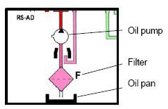
7 Transmission Fluid Level No Dipstick or Dipstick tube. Fluid level check using overflow method. Oil pan has overflow pipe clipped onto the pan above drain plug. Fluid level must be checked at specified temperature.

8 Transmission Fluid Level A new oil pan is used and can be identified by its design and Part No The white overflow pipe has been increased in length and as a result will hold an extra 0.2 litres of fluid. NEW OLD Pan depth +3mm Overflow pipe +13.5mm
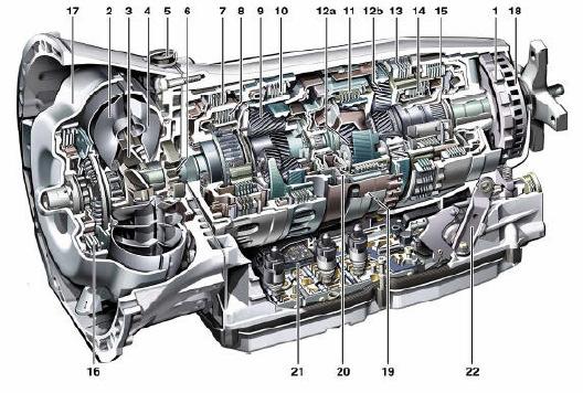
9 Major Components
10 Major Component Legend 1. Park Pawl 2. Turbine wheel 3. Stator 4. Impeller 5. Transmission Breather 6. Oil pump 7. B1 Brake 8. K1 Clutch 9. Ravigneaux Gearset 10. B3 Brake 11. K2 Clutch 12a. Front Simple Planetary 12b. Rear Simple Planetary 13. BR Brake 14. K3 Clutch 15. B2 Brake 16. Torque Converter Clutch 17. Torque Converter housing 18. Output speed exciter ring 19. Internal speed ring magnet 20. Turbine speed ring magnet 21. Electro-hydraulic control unit 22. Range Selector Lever


11 Torque Converter Same as used in some transmissions Fluid capacity 4 Litres Lock-up can be activated in all 7 gears Incorporates damper springs to reduce vibration 1. Lock-up with torsional damper springs 2. Turbine wheel 3. Stator 4. Impeller

12 Torque Converter The Torque Converter is never fully locked In 1 st and 2 nd gears if throttle and output speed are in zone A the Torque N converter is open A = OPEN N = OUTPUT SPEED B = SLIP-MODE D = % THROTTLE B If throttle and output A speed are in zone B it operates in slip-mode in all 7 forward gears D If temperature exceeds 140 Deg C the TCC is switched off and lower gear selected. (DTC 2226)

13 Transmission Housing Torque converter housing is die-cast Aluminium Transmission is die-cast magnesium (2Kg weight reduction) New aluminium bolts must be used if removed and tightening torques should be adhered to Thread repairs to magnesium case is permissible

14 Transmission Housing Housing gasket is made from aluminium sheet coated with elastomer and can be re-used The gasket has a lip that faces forward to direct water away from the casing Salt water can damage magnesium in as little as 8 weeks


15 Oil Cooler Pipes The transmission cooler pipes are sealed with an O ring and retained using a bolt

16 Oil Pump This transmission as like the uses a crescent style pump The suction side has a recess to help reduce oil intake noise. This is also expected to be phased in on the To improve performance at high temperatures and also reduce weight it is expected that the pump and gears will soon be made from aluminium


17 Ravigneaux Gear Set The advantages of the Ravigneaux Gear set are that it combines two simple planetary sets into one simple unit It increases available gear ratios compared to a simple planetary set. It has two ring gears Short planetary gear Long planetary gear Sun gear Planetary gear carrier Small ring gear Large ring gear

18 Ravigneaux Gear Set The input from the torque converter turbine arrives at the gear set via the small ring gear The long planetary gear transfers drive via the the sun gear or short planetary gear depending upon the applied member Short Planetary Gear Long Planetary Gear Sun Gear Planetary Gear Carrier Small Ring Gear Large Ring Gear

19 Multi-Disc Brakes B1 & B3 Multi-disc brakes use single sided plates Outer teeth B1 B3 Inner teeth BR B2
20 Multi-Disc Clutches All multi-disc clutches use single sided plates Outer teeth K3 K1 K2 Inner teeth
21 Shift Application Chart In neutral 2 elements are applied, so only 1 element needs to apply when selecting either D or R A gear change is made by applying an element whilst disengaging another GEAR RATIO B1 B2 B3 BR K1 K2 K N(1) R(1) R(2) (1) = S Mode (2) = C Mode
22 Power Flow 1 st Gear
23 Power Flow 2nd Gear
24 Power Flow 3rd Gear
25 Power Flow 4th Gear
26 Power Flow 5th Gear
27 Power Flow 6th Gear

28 Power Flow 7th Gear
29 Power Flow Reverse (S mode)
30 Power Flow Reverse (C mode)

31 Shift Sequences In addition to sequentially shifting the can downshift skipping gears providing the one element applied, one element released principle B1 B2 B3 K1 K2 K3 7 th 6 th 5 th 4 th 3 rd 2 nd 1st

32 Electro-hydraulic Module Uses same principle as of controlling hydraulics with electronics The module will adapt for optimal shift quality Mounted to the Valve body are components that control, monitor and enable the gear shifts
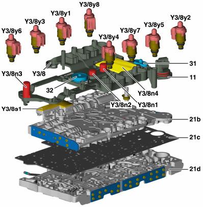
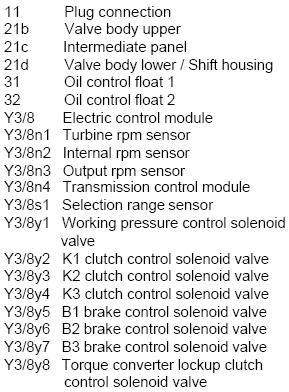
33 Electro-hydraulic Module


34 Electro-hydraulic Module Each Valve body is individually tested Hydraulic pressures and currents are measured Values are evaluated and corresponding algorithms are written to the modules permanent memory This ensures that the module is calibrated to that valve body Once this process is complete the valve body is installed in the transmission

35 Electric Control Module The task of the Electric Control module is to - Evaluate various input signals Calculate shift points according to programming Evaluate gear shifts and attempt to adapt Activate 8 control solenoid valves Temperature Sensor Flashable capable software using SDS / DAS
 5.")
36 Electric Control Module As the control module is integrated into the valve body, wiring to the transmission has been greatly reduced Electrical plug has only 5 pins 1. = CAN C High 2. = CAN C Low 3. = To diagnostic 11/4 4. = Circuit 87 (relay & fuse) 5. = Circuit 31

37 Electric Control Module The plug connector is sealed by two O rings and one square section seal Plug connector O Rings Square section seal

38 Electric Control Module Y3/8n3 Output speed sensor 11 Electrical connector Y3/8n1 Input speed sensor Y3/8n2 Internal speed sensor Y3/8s1 Range selector sensor 11/4 Diagnostic socket Y3/8n4 Electric control module Y3/8y1 Y3/8y8 Solenoids
39 Information Received Over CAN C 1. Engine RPM 2. Engine coolant temperature 3. Throttle pedal position 4. Engine load 5. ESP signals 6. Cruise control signals 7. ESM (Shifter position) Information Received Directly 1. Speed sensors 2. Range selector sensor 3. Transmission fluid temperature
40 Speed Sensors Y3/8n1 & n2 Front speed sensor (Y3/8n1) monitors turbine speed (input shaft / small ring gear) Centre speed sensor (Y3/8n2) monitors Ravigneaux planet carrier speed These sensors are Active speed sensors They permit a signal to be read through other Non-ferrous parts The magnets are moulded in plastic rings and secured inside aluminium flanges Ring magnet Parking gear Exciter ring Output sensor Turbine sensor Internal sensor Integrated ring magnet

41 Speed Sensors Y3/8n1 & n2 Y3/8n1 Y3/8n2

42 Speed Sensor Y3/8n3 The Y3/8n3 sensor measures transmission output speed from a ring attached to the park gear It is a Hall effect type sensor Replaces wheel speed information previously used to calculate shift points and detects gear slip Direct input to electric control module Improves reaction time to changes in vehicle speed Ring magnet Parking gear Exciter ring Output sensor Turbine sensor Internal sensor Integrated ring magnet

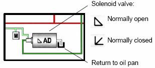
43 Solenoid Valves The solenoids are actuated by the transmission control module using variable current Each solenoid valve has a filter screen fitted The 4 solenoids shown are normally closed. No current / no pressure. Pressure increases with current B2 Brake B3 Brake K1 Clutch TCC Valve
44 Solenoid Valves The valves shown are normally open. They produce maximum pressure with no current applied and decrease pressure with current These valves are responsible for limp-home mode when all valves are de-energised K2 Clutch Pressure Regulator K3 Clutch B1 Brake

45 Hydraulic Diagram Shown in 2 nd gear

46 Hydraulic Diagram Legend

47 Range Selector Sensor (Y38s1) The sensor is soldered onto the ribbon cable of the electric control module This sensor cannot be replaced separately It records the position of the range selection lever It is a PLCD, Permanent magnetic Linear Contactless Displacement sensor It is constructed of a soft magnetic core surrounded by a wire along it s length with additional coil at each end It has a permanent magnet on the range selector valve which changes it s magnetic field and output voltage of the sensor WARNING This sensor must be learned in or Limp-home will occur

48 Fluid Level Control This feature reduces the possibility of gear sets running in fluid and causing ATF foaming Two floats are used because the transmission is 41mm longer than the and fluid has a tendency to run to the front of the case under sharp braking Rear level float Front level float

49 Oil Level Check Limp-home Modes DTC s EDAC Check and Diagnosis Replacement of Transmission or Control Module SCN & CVN Coding
50 Fluid Level The fluid level should be checked a specific fluid temperatures using SDS / DAS There are two different oil pan designs with different fill specifications Mercedes recommend using a special filling tool to add fluid via the drain bung Old Pan Design New pan Design WIS document No. Initial fill check Level check Fluid fill total S P-0002A 30 deg C Deg C 9.5 Litres S P-0002B 40 Deg C Deg C 9.7 Litres
51 Emergency Function / Limp-home Mode This transmission has a variety of Limp-home modes that allows limited functionality If a Shift solenoid is defective the gear or gears effected are blocked An example of this would be if the Y3/8y7 (B3) were defective then 1 st,7 th and Reverse gear in S mode would be blocked If an hydraulic fault prevents a gear from engaging then the previous engaged gear is retained If a TCM fault occurs whilst driving all solenoids are switched off and the vehicle defaults to 6 th gear with full pressure After shifting to Park oil pressure from K2 solenoid is directed to B2 / BR solenoid circuit via emergency operation valves Oil pressure can now be directed to B2 or BR elements using the Range selector valve D = 2 nd gear R = Reverse gear
52 Diagnostic Trouble Codes (DTC( DTC s) The TCM has over 100 possible fault codes When these faults occur they have a priority order Only a maximum of 16 fault codes can be stored at any one time If more than 16 fault codes occur then the 16 with the highest priority will be stored Fault codes can be accessed using SDS / DAS
53 Control Module Software The Control Module Software can be Flashed using the appropriate update CD Rom disc using SDS / DAS This process does not erase the factory settings that were written to the module during manufacture Flashing of the control module would be performed after replacing the transmission or the electro-hydraulic valve body. This is part of the installation process to release transport protection and personalise the module Once the module is personalised it will not work in another vehicle Flashing could also be performed to correct a specific shifting issue
54 Control Module Software European and American legislation requires that control modules be codable with Software Calibration Number (SCN) to prevent manipulation of software As of the year 2004 transmission control modules incorporate SCN coding SCN coding will need to be entered using SDS / DAS after every software update Failure to enter the SCN code after software update may result in the engine not starting. Ensure SCN coding is available before programming a control module The SCN code for the transmission can be obtained from the password protected site via NetStar

55 SCN Coding After installing the software with SDS / DAS navigate to this screen for the software version in the vehicle to determine the SCN code. The last 4 digits of the MB object number changes with the software version This example shows software version, the latest software release is

56 The End Thank you
Mercedes Benz has introduced
 THE ART OF THEORY The Strategy of the 722.9 (NAG2) by Hank Blair members.atra.com www.atra.com Mercedes Benz has introduced the 5 th generation electronically controlled transmission, called the 722.9
Cars Drivetrain 9-Speed Automatic Transmission (725.0) AKUBIS direct special Final Test Go Hand-outs for participants
 AKUBIS direct special Final Test Go Hand-outs for participants") Global Training The finest automotive learning Cars Drivetrain 9-Speed Automatic Transmission (725.0) AKUBIS direct special Final Test Go Hand-outs for participants T0831E As at 06.09.2013 This document
Global Training The finest automotive learning Cars Drivetrain 9-Speed Automatic Transmission (725.0) AKUBIS direct special Final Test Go Hand-outs for participants T0831E As at 06.09.2013 This document
LX AUTOMATIC TRANSMISSION NAG1 - SERVICE INFORMATION TABLE OF CONTENTS
 LX AUTOMATIC TRANSMISSION NAG1 - SERVICE INFORMATION 21-495 AUTOMATIC TRANSMISSION NAG1 - SERVICE INFORMATION TABLE OF CONTENTS page AUTOMATIC TRANSMISSION NAG1 - SERVICE INFORMATION DESCRIPTION...496
AUTOMATIC TRANSMISSION (5AT)
") (5AT) GENERAL 1. General To improve the dynamic performance and fuel efficiency of the vehicle, a new 5-speed automatic transmission is developed. The features of this new automatic transmission are as
(5AT) GENERAL 1. General To improve the dynamic performance and fuel efficiency of the vehicle, a new 5-speed automatic transmission is developed. The features of this new automatic transmission are as
CHASSIS. Transmission Type 1st nd rd th Gear Ratio
 CH-2 CHASSIS AA80E AUTOMATIC TRANSMISSION DESCRIPTION An AA80E automatic transmission is used. This automatic transmission is a compact, lightweight and high-capacity 8-speed sport direct shift gearbox.
DESCRIPTION. Chrysler NCV3 Service Info Section 08 > Electronic Modules > MODULE, Transmission Control Information
 DESCRIPTION The transmission control module (TCM) receives, processes and sends various digital and analog signals related to the automatic transmission. In addition, it processes information received
OPERATION FIRST GEAR POWERFLOW TJ - JEEP WRANGLER - 4.0L 6 CYL (MPI) 21 - Transmission and Transfer Case/Automatic - 42RLE/Operation
 21 - Transmission and Transfer Case/Automatic - 42RLE/Operation") 2006 - TJ - JEEP WRANGLER - 4.0L 6 CYL (MPI) 21 - Transmission and Transfer Case/Automatic - 42RLE/Operation OPERATION The 42RLE transmission ratios are: GEAR RATIO First 2.84 : 1 Second 1.57 : 1 Third
2006 - TJ - JEEP WRANGLER - 4.0L 6 CYL (MPI) 21 - Transmission and Transfer Case/Automatic - 42RLE/Operation OPERATION The 42RLE transmission ratios are: GEAR RATIO First 2.84 : 1 Second 1.57 : 1 Third
 Page 1 of 10 Main Components and Functions Torque Converter 1 Cover (Part of 7902) 2 Converter Damper Plate 3 O-Ring (Part of 7902) 4 Turbine Assembly (Part of 7902) 5 Selective Spacer 6 Thrust Washer
Continuously Variable Transaxle Specification. Forward/Reverse Switching Mechanism Double Pinion Type Planetary Gear
 CVT SYSTEM > GENERAL OUTLINE 1. A newly developed K41B Continuously Variable Transaxle (CVT) is used for the1nr-fe engine models. 2. The K41B CVT, including a pair of the pulleys and the belt in the shift
1. GENERAL INFORMATION
 368001 023 1. GENERAL INFORMATION DSI M78 Automatic Transmission is based on the transmission in the vehicle with D20DT engine for EURO III or EURO IV. Differences: changed some components (torque converter
Continuously Variable Transaxle Specification. Forward/Reverse Switching Mechanism Double Pinion Type Planetary Gear
 CVT SYSTEM > GENERAL OUTLINE 1. A newly developed K41A Continuously Variable Transaxle (CVT) is used for the1kr-fe engine models. 2. The K41A CVT, including a pair of the pulleys and the belt in the shift
CHASSIS AUTOMATIC TRANSAXLE. Destination New Model Previous Model Change (from previous model)
") CHASSIS AUTOMATIC TRANSAXLE CH-37 U341E AUTOMATIC TRANSAXLE 1. General The compact and high-capacity 4-speed U341E automatic transaxle [Super ECT (Electronic Controlled Transaxle)] is used. The following
CHASSIS AUTOMATIC TRANSAXLE CH-37 U341E AUTOMATIC TRANSAXLE 1. General The compact and high-capacity 4-speed U341E automatic transaxle [Super ECT (Electronic Controlled Transaxle)] is used. The following
ZF 6HP26 Automatic Transmission Component Location
 Published : Apr 8, 2005 ZF 6HP26 Automatic Transmission Component Location Item Part Number Description 1 - PRND LCD display 2 - M/S LCD display 3 - Selector lever assembly 4 - Instrument cluster 5 - Automatic
2007 Dodge Nitro R/T
 1 - TURBINE 2 - IMPELLER 2007 Dodge Nitro R/T CONVERTER-TORQUE DESCRIPTION TORQUE CONVERTER Fig. 267: Cutaway View Of Torque Converter Fig. 268: Impeller 2007 Dodge Nitro R/T 3 - STATOR 4 - INPUT SHAFT
Description. Cooling. Mechatronik module. Automatic Transmission (07.01) Transmission (07.00) transmission fault-finding.
 Transmission (07.00) transmission fault-finding.") Automatic Transaxle (07.01) Description The ZF 6HP26 automatic gearbox has the following features: Six forward speeds and One reverse A torque converter with an integral converter lock-up clutch Electronic
Automatic Transaxle (07.01) Description The ZF 6HP26 automatic gearbox has the following features: Six forward speeds and One reverse A torque converter with an integral converter lock-up clutch Electronic
6-speed automatic transmission 09D
 Service. Self-Study Programme 300 6-speed automatic transmission 09D Design and function Compared to the 5-speed automatic transmission, the 09D 6-speed automatic transmission provides: a reduction in
6-Speed Automatic Transmission 09G/09M Design and Function
 6-Speed Automatic Transmission 09G/09M Design and Function Self-Study Program Course Number 851503 Volkswagen of America, Inc. Service Training Printed in U.S.A. Printed 04/05 Course Number 851503 2005
Automatic Transmission
 Curriculum Training Automatic Transmission E58562 Technical Training T201.1 en 12/2004 201 To the best of our knowledge, the illustrations, technical information, data and descriptions in this issue were
Table of Contents. E70 Transmissions
 Table of Contents Subject Page New Transmissions for E70....................................5 Changes.......................................................5 Technical Data...............................................6
 Page 1 of 13 437: Transmission control module (TCM), TF-80SC AWD XC90, 2007, D5244T4, TF-80SC AWD, L.H.D, YV1CM714671338226, 338226 7/7/2016 PRINT 437: Transmission control module (TCM), TF-80SC AWD Adaptation
Shift Solenoid B (SSB) and Shift Solenoid D (SSD) Inverse Proportional VFS 2761
 and Shift Solenoid D (SSD) Inverse Proportional VFS 2761") Item Description 1 Shift Solenoid A (SSA) Variable Force Solenoid (VFS) 2 Shift Solenoid C (SSC) VFS SSB and SSD use inverse proportional operation. As the current from the PCM decreases, the pressure
Item Description 1 Shift Solenoid A (SSA) Variable Force Solenoid (VFS) 2 Shift Solenoid C (SSC) VFS SSB and SSD use inverse proportional operation. As the current from the PCM decreases, the pressure
SECTION : Automatic Transmission
 307-01-1 Automatic Transmission 307-01-1 SECTION : 307-01 Automatic Transmission VEHICLE APPLICATION : 2003.0 BA Falcon CONTENTS SPECIFICATIONS PAGE Specifications...307-01-3 DESCRIPTION AND OPERATION
AISIN WARNER. 1. With the selector lever in Park, start the engine and warm it to operating temperature.
 AISIN WARNER 249 Manual Code Retrieval Preliminary Test: 1. With the selector lever in Park, start the engine and warm it to operating temperature. 2. Turn the ignition switch to the Off position, then
Transmissions. Service Training Course No. 200 WARNING: WHILE SERVICING AND TESTING VEHICLES AND VEHICLE SYSTEMS, TAKE ALL
 Service Training Course No. 200 Transmissions This publication is intended for instructional purposes only. Always refer to the appropriate Jaguar Service publication for specific details and procedures.
Transmission Description
 Page 1 of 23 Published: Feb 1, 2007 Transmission Description COMPONENT LOCATION Item Part Number Description 1 Transmission selector lever assembly 2 Cable bracket 3 Automatic transmission 4 Transmission
DSI M78 6-SPEED A/T / / / / / DSI M78 6-SPEED A/T GENERAL INFORMATION OVERVIEW AND OPERATION PROCESS
 DSI M78 6SPEED A/T 311001/365001/366001/368001/372101/921001 DSI M78 6SPEED A/T GENERAL INFORMATION 1. DSI M78 6SPEED AUTOMATIC TRANSMISSION GENERAL... 2. STRUCTURE CHARACTERISTICS AND SPECIFICATIONS...
Geo Prizm ( LSi) Toyota Celica 1.8L (1994)
 Toyota Celica 1.8L (1994)") Page 1 of 140 ARTICLE BEGINNING APPLICATION TRANSMISSION APPLICATIONS Application Geo Prizm (1993-94 LSi) Toyota Celica 1.6L (1993) Celica 1.8L (1994) Celica 2.2L (1993) Corolla 1.8L MR2 Paseo Transaxle
Page 1 of 140 ARTICLE BEGINNING APPLICATION TRANSMISSION APPLICATIONS Application Geo Prizm (1993-94 LSi) Toyota Celica 1.6L (1993) Celica 1.8L (1994) Celica 2.2L (1993) Corolla 1.8L MR2 Paseo Transaxle
Module 5: Cooling Fundamentals
 Terms and Definitions Major Mechanical Parts of a Four Speed Auto Transmission Parts of a Planetary Gear System Planetary Gear System Operation Speed, Torque, and Directional Function Fluid Pump and Pressure
Shift Solenoid "B" Performance (Shift Solenoid Valve S2)
") 86 A750E AUTOMIC TRANSMISSION AUTOMIC TRANSMISSION SYSTEM DTC P0756 Shift Solenoid "B" Performance (Shift Solenoid Valve S2) DESCRIPTION The ECM uses signals from the output shaft speed sensor and input
86 A750E AUTOMIC TRANSMISSION AUTOMIC TRANSMISSION SYSTEM DTC P0756 Shift Solenoid "B" Performance (Shift Solenoid Valve S2) DESCRIPTION The ECM uses signals from the output shaft speed sensor and input
Rear Drive Axle and Differential
 Page 1 of 13 Rear Drive Axle and Differential GENERAL Item Part Number Description A - Electronic rear differential B - Open rear differential 1 - Rear driveshaft 2 - Electronic rear differential 3 - RH
Swirl Flaps. A = Non swirl not active. B = Swirl active
 Swirl Flaps A = Non swirl not active B = Swirl active 35 Swirl Flaps 36 Swirl Flap Operating Parameters 37 Swirl Flap Functional Diagram 12 Intake manifold 1 Swirl flap 22/9 Aneroid capsule swirl flap
U340E AND U441E AUTOMATIC TRANSAXLES
 ASSIS U340E AND U441E AUTOMATIC TRANSAXLES -41 U340E AND U441E AUTOMATIC TRANSAXLES DESCRIPTION The new model uses 2 types (U340E, U441E) of automatic transaxle. A U340E automatic transaxle is provided
AUTOMATIC TRANSMISSION (DC 5-SPEED) GENERAL 1. AUTOMATIC TRANSMISSION OVERVIEW
 GENERAL 1. AUTOMATIC TRANSMISSION OVERVIEW") 02-4 AUTOMATIC TRANSMISSION () GENERAL 1. AUTOMATIC TRANSMISSION OVERVIEW DC 5-speed Automatic Transmission Assembly T-Tronic DC 5-speed automatic transmission is an electronically controlled 5-speed transmission
02-4 AUTOMATIC TRANSMISSION () GENERAL 1. AUTOMATIC TRANSMISSION OVERVIEW DC 5-speed Automatic Transmission Assembly T-Tronic DC 5-speed automatic transmission is an electronically controlled 5-speed transmission
ELECTRONIC CONTROL SYSTEM. 1. General CH-16 CHASSIS - U340E AUTOMATIC TRANSAXLE
 CH-16 ELECTRONIC CONTROL SYSTEM 1. General The electronic control system of the U340E automatic transaxle consists of the controls listed below. System Clutch Pressure Control (See page CH-20) Line Pressure
44 - AUTOMATIC GEARBOX
 44 - AUTOMATIC GEARBOX CONTENTS Page ZF AUTO DESCRIPTION AND OPERATION AUTOMATIC TRANSMISSION - DESCRIPTION... 4 OPERATION... 19 ADJUSTMENT SELECTOR CABLE... 1 GEARBOX - DRAIN AND REFILL - FROM 99MY...
Shift Solenoid "B" Performance (Shift Solenoid Valve S2)
") 88 A750F AUTOMIC TRANSMISSION AUTOMIC TRANSMISSION SYSTEM DTC P0756 Shift Solenoid "B" Performance (Shift Solenoid Valve S2) DESCRIPTION The ECM uses signals from the output shaft speed sensor and input
88 A750F AUTOMIC TRANSMISSION AUTOMIC TRANSMISSION SYSTEM DTC P0756 Shift Solenoid "B" Performance (Shift Solenoid Valve S2) DESCRIPTION The ECM uses signals from the output shaft speed sensor and input
U140E AND U241E AUTOMATIC TRANSAXLE
 CH-125 U140E AND U241E AUTOMATIC TRANSAXLE DESCRIPTI The 02 Camry line-up uses the following types of automatic transaxles: 2AZ-FE U241E 1MZ-FE U140E These automatic transaxles are compact and high-capacity
Advanced Auto Tech Worksheet Auto Trans & Transaxle Chapter 40 Pages Points Due Date
 Advanced Auto Tech Worksheet Name Auto Trans & Transaxle Chapter 40 Pages 1173 1215 107 Points Due Date 1. Automatic transmissions are operated by hydraulics as well as electronics to select according
DTC Summaries. W5A-580 Transmission Control System 1998 MY
 DTC Summaries W5A-580 Transmission Control System 1998 MY OBD II MONITORING CONDITIONS: When testing for OBD II DTC reoccurrence, it can be determined if the Service Drive Cycle was of sufficient length
DI 244 DIAGNOSTICS AUTOMATIC TRANSMISSION DIB30 01 PRE CHECK
 DI244 DIAGNOSTICS PRECHECK DIB3001 1. DIAGNOSIS SYSTEM (a) Description When troubleshooting OBD II vehicles, the only difference from the usual troubleshooting procedure is that you connect to the vehicle
MEDIUM DUTY TRUCK. Presented By. ATSG s PETE LUBAN
 MEDIUM DUTY TRUCK Presented By ATSG s PETE LUBAN 1/3/2M WWW.ATSG.COM 2/3/1M 3/3 1000/2000 SERIES Transmission code identification PPT 1 0 0 0 MHS HS Highway Series MHS Motor Home Series EVS Emergency Vehicle
TROUBLESHOOTING BASIC TROUBLESHOOTING AT1 14 A340E A340F AUTOMATIC TRANSMISSION
 AT114 BASIC Before troubleshooting an electronically controlled transmission, first determine whether the problem is electrical or mechanical. To do this, just refer to the basic troubleshooting flowchart
AUTOMATIC TRANSMISSION
 SECTION 5A AUTOMATIC TRANSMISSION CAUTION: isconnect the negative battery cable before removing or installing any electrical unit or when a tool or equipment could easily come in contact with exposed electrical
Workbook. Transmission Technology. Transmission External ZF training P a g e 1
 Workbook Technology P a g e 1 Table of content 1. History... 3 2. 6HP Design... 4 3. Adaption... 25 3. Oil change Service and Mechatronic... 38 4. 6HP Overhaul... 60 6. 8 HP... 80 7. Identification of
TRANSMISSION PARTS BOOK
 TRANSMISSION PARTS BOOK SS-6, SS-636, SS-836 SS-8, SS-08 DATE: 7-3-96 CLARK 8000 SERIES INTERMEDIATE DROP BARAGA PRODUCTS, INC. 55 N. Superior Ave. Baraga, MI 9908-08 Ph. (906) 353-6675 Fax (906) 353-75J
SECTION ZF TRANSMISSION
 10-103.04/ 1 2009JL16 SECTION 10-103.04 GENERAL DESCRIPTION See Figure 1. The ZF-Ecomat transmission consists of a hydrodynamic torque converter, with a lock-up clutch for direct drive, a hydrodynamic
PRE CHECK DI 456. w/ Tachometer. w/o Tachometer. Hand held Tester AUTOMATIC TRANSMISSION (A340E, A340F) 2003 TOYOTA TACOMA (RM1002U) D10837 D00729
 2003 TOYOTA TACOMA (RM1002U) D10837 D00729") DI456 w/ Tachometer w/o Tachometer D10837 PRECHECK DI8Z403 1. DIAGNOSIS SYSTEM (a) Description When troubleshooting OBD II vehicles, the only difference from the usual troubleshooting procedure is that
DI456 w/ Tachometer w/o Tachometer D10837 PRECHECK DI8Z403 1. DIAGNOSIS SYSTEM (a) Description When troubleshooting OBD II vehicles, the only difference from the usual troubleshooting procedure is that
4 Spd. Automatic Transmission 096
 4 Spd. Automatic Transmission 096 00 - General, Technical data Transmission identification Code letters, model/engine applications, ratios, equipment Capacities Repair instructions 01 - On Board Diagnostic
A5S 360R GM Introduction... 4 System and Components Overview
 Table of Contents AUTOMATIC TRANSMISSIONS Subject Page A5S 360R GM 5............................................3 Introduction.............................................. 4 System and Components Overview
SERVICE MANUAL Gearbox - Allison AT545 - Gearbox Installation
 Gearbox - Allison AT545 - Gearbox Installation Oil level dipstick Gearbox oil cooler Auxiliary oil filter Modulator Page 3.4 Gearbox - Allison AT545 Checking Oil Level The dipstick and filler are situated
Troubleshooting the Transmission Hydraulic System
 Testing and Adjusting IT28F INTEGRATED TOOLCARRIER POWER TRAIN Testing And Adjusting Introduction Reference: For Specifications with illustrations, refer to SENR5974, IT28F Integrated Toolcarrier Power
Shift Solenoid "A" Performance (Shift Solenoid Valve S1)
") 78 DTC P0751 Shift Solenoid "A" Performance (Shift Solenoid Valve S1) DESCRIPTION The ECM uses signals from the output shaft speed sensor and input speed sensor to detect the actual gear position (1st,
78 DTC P0751 Shift Solenoid "A" Performance (Shift Solenoid Valve S1) DESCRIPTION The ECM uses signals from the output shaft speed sensor and input speed sensor to detect the actual gear position (1st,
ZF 6HP26 / 6HP28 6HP26 6HP28. Automatic Transmission Spare Parts Catalog
 ZF 6HP26 / 6HP28 6HP26 6HP28 Automatic Transmission Spare Parts Catalog Warranty Information Warranty coverage for ZF passenger car transmission spare parts and kits covers the first 12 months after installation
Diagnostic Trouble Code (DTC) Charts
 Charts") SECTION 307-01: Automatic Transaxle/Transmission 5R55S 2009 Mustang Workshop Manual DIAGNOSIS AND TESTING Procedure revision date: 06/30/2009 Diagnostic Trouble Code (DTC) Charts DTC Chart **May also be
SECTION 307-01: Automatic Transaxle/Transmission 5R55S 2009 Mustang Workshop Manual DIAGNOSIS AND TESTING Procedure revision date: 06/30/2009 Diagnostic Trouble Code (DTC) Charts DTC Chart **May also be
Technical Bulletin # 1251
 Transmission: Subject: Application: Issue Date: CD4E TCC Slip Code Diagnosis Ford, Mercury and Mazda May 2009 CD4E TCC Slip Code Diagnosis Once the check engine light illuminates, the transmission will
5-speed Automatic Gearbox 09A/09B
 Service. Self-Study Programme 232 5-speed Automatic Gearbox 09A/09B Design and Function The new 5-speed automatic gearbox The new automatic gearbox is intended for installation in the Volkswagen and Audi
CONTINUOUSLY VARIABLE TRANSMISSION (CVT)
") 23-1 GROUP 23 CONTINUOUSLY VARIABLE TRANSMISSION () CONTENTS........................... 23-2 GENERAL INFORMATION............. 23-2 PRINCIPLE OF IMPROVEMENTS IN FUEL ECONOMY AND PERFORMANCE WITH......................................
23-1 GROUP 23 CONTINUOUSLY VARIABLE TRANSMISSION () CONTENTS........................... 23-2 GENERAL INFORMATION............. 23-2 PRINCIPLE OF IMPROVEMENTS IN FUEL ECONOMY AND PERFORMANCE WITH......................................
DTC Summaries. 5 HP 24 Transmission Control System 1997 MY
 DTC Summaries 5 HP 24 Transmission Control System 1997 MY OBD II MONITORING CONDITIONS: When testing for OBD II DTC reoccurrence, it can be determined if the Service Drive Cycle was of sufficient length
2011 Dodge or Ram Truck RAM 3500 Truck 4WD L6-6.7L DSL Turbo
 1 of 10 10/14/2013 9:23 AM 2011 Dodge or Ram Truck RAM 3500 Truck 4WD L6-6.7L DSL Turbo Vehicle» A L L Diagnostic Trouble Codes ( DTC )» Testing and Inspection» P Code Charts» P0732 P0732-GEAR RATIO ERROR
GM 4L80-E, 4L85-E SURE CURE KIT
 GM 4L80-E, 4L85-E SURE CURE KIT PART NUMBER SC-4L80E INSTALLATION GUIDE Parts are labeled here in order of installation. See page 2 for details on Sure Cure kit contents. See Sure Cure instruction booklet
Transmission Electronic Control System
 SECTION 307-01: Automatic Transaxle/Transmission 5R55S 2009 Mustang Workshop Manual DESCRIPTION AND OPERATION Procedure revision date: 05/23/2008 Transmission Electronic Control System Electronic System
GM 4L80-E, 4L85-E SURE CURE KIT
 GM 4L80-E, 4L85-E SURE CURE KIT PART NUMBER SC-4L80E INSTRUCTION BOOKLET Parts are labeled here in order of installation. See page 2 for details on Sure Cure kit contents. See Sure Cure instruction booklet
DC-5 SPEED AUTOMATIC TRANSMISSION
 01-3 DC-5 SPEED AUTOMATIC TRANSMISSION GENERAL 1. SPECIFICATIONS 01-4 01-5 OVERVIEW AND OPERATION PROCESS 1. OVERVIEW 2WD 4WD DC 5-Speed Automatic Transmission DCAG 5-speed automatic transmission is an
Automatic Transmissions & Transaxles
 ATASA 5 th Study Guide Chapter 40 Pages 1173 1215 Automatic Transmissions /Transaxles 107 Points Be Certain to Read the Summary 1. Automatic transmissions are operated by hydraulics as well as electronics
The electro-mechanical power steering with dual pinion
 Service Training Self-study programme 317 The electro-mechanical power steering with dual pinion Design and function The electro-mechanical power steering has many advantages over the hydraulic steering
ZF4HP16. Technical Bulletin # Signal Combination L1 L2 L3 L4 P R N D
 Transmission: Subject: Application: Issue Date: Technical Bulletin # 1308 ZF4HP16 Electronical Components Description 2005 Suzuki Forenza L4-2.0L February, 2010 ZF4HP16 Electronical Components Description
3. Engine Control System Diagram
 ENGINE - 2UZ-FE ENGINE 59 3. Engine Control System Diagram Ignition Switch Fuel Pump Relay Fuel Pump Resister Circuit Opening Fuel Relay Filter Intake Temp. Mass Air Flow Meter Throttle Position Fuel Pump
6-speed Automatic Gearbox 09G/09K/09M
 Service Training Self-study Programme 309 6-speed Automatic Gearbox 09G/09K/09M The 6-speed automatic gearbox from the Japanese manufacturer AISIN is used in the following Volkswagen vehicles: Code Maximum
ZF 6HP19X / 6HP21X 6HP19X 6HP21X. Automatic Transmission Spare Parts Catalog
 ZF 6HP19X / 6HP21X 6HP19X 6HP21X Automatic Transmission Spare Parts Catalog Warranty Information Warranty coverage for ZF passenger car transmission spare parts and kits covers the first 12 months after
Amarok 2012 The 8-speed automatic gearbox 0CM Design and function
 Service Training Commercial Vehicles Self-Study Programme Technology 507 Amarok 2012 The 8-speed automatic gearbox 0CM Design and function The 8-speed automatic gearbox in the Amarok With a combustion
Powertrain DTC Summaries EOBD
 Powertrain DTC Summaries Quick Reference Diagnostic Guide Jaguar X-TYPE 2.0 L 2002.25 Model Year Refer to page 2 for important information regarding the use of Powertrain DTC Summaries. Jaguar X-TYPE 2.0
Not Just Another. Apair of new transmissions LET'S PLAY BALL. by Lance Wiggins members.atra.com
 Not Just Another CVT LET'S PLAY BALL Not Just Another CVT by Lance Wiggins members.atra.com Apair of new transmissions were introduced in the 2014 Chevrolet Spark (C Body): The CVT-7 and 1ET35. We ll take
6-speed automatic transmission E60, E53. VS-22 je Baugruppe/Group: (040) 09/2003. Introduction
 09/2003. Introduction") VS-22 je Baugruppe/Group: 24 24 01 03 (040) 6-speed automatic transmission E60, E53 weltweit Datum/Date: 09/2003 Introduction The 6-speed automatic transmissions GA6HP19Z and GA6HP26Z have been jointly
VS-22 je Baugruppe/Group: 24 24 01 03 (040) 6-speed automatic transmission E60, E53 weltweit Datum/Date: 09/2003 Introduction The 6-speed automatic transmissions GA6HP19Z and GA6HP26Z have been jointly
CH-23 CHASSIS AA80E AUTOMATIC TRANSMISSION. Function of Shift Solenoid Valves. Spool Valve. Hydraulic Pressure. Sleeve. Current. Shift Solenoid Valve
 CH-23 Spool Valve Hydraulic Sleeve Shift Solenoid Valve SL2 Current 036CH29TE Spool Valve Hydraulic Sleeve Shift Solenoid Valve SLU Current 036CH27TE Spool Valve Hydraulic Sleeve Shift Solenoid Valve SLT
ZF 6HP26X / 6HP28X 6HP26X 6HP28X. Automatic Transmission Spare Parts Catalog
 ZF 6HP26X / 6HP28X 6HP26X 6HP28X Automatic Transmission Spare Parts Catalog Warranty Information Warranty coverage for ZF passenger car transmission spare parts and kits covers the first 12 months after
HOLINGER SF GEARBOX MANUAL
 HOLINGER SF GEARBOX MANUAL Approved By: Leigh Nash Date: 26/05/2011 Rev: D Date: 11/11 Holinger Engineering Gearbox Manual Page 1 FOREWORD The Holinger SF is a sequential-shift transaxle designed for use
DISASSEMBLY AND ASSEMBLY
 307-01-1 Automatic Transaxle/Transmission 307-01-1 DISASSEMBLY AND ASSEMBLY Transaxle Special Tool(s) Dial Indicator Gauge With Holding Fixture 100-002 (TOOL-4201-C) Special Tool(s) Test Plate Screw Set,
2002 F-Super Duty /Excursion Workshop Manual
 Page 1 of 25 SECTION 307-01: Automatic Transaxle/Transmission 2002 F-Super Duty 250-550/Excursion Workshop Manual ASSEMBLY Procedure revision date: 05/23/2001 Transmission Special Tool(s) Remover, O-Ring
AUTOMATIC TRANSMISSION (DIAGNOSTICS)
") AUTOMATIC TRANSMISSION (DIAGNOSTICS) Basic Diagnostic Procedure 1. Basic Diagnostic Procedure A: PROCEDURE Is the unit that is thought to Go to step 2. influence the AT problem working properly? 1 CHECK
AUTOMATIC TRANSMISSION (DIAGNOSTICS) Basic Diagnostic Procedure 1. Basic Diagnostic Procedure A: PROCEDURE Is the unit that is thought to Go to step 2. influence the AT problem working properly? 1 CHECK
SUBJECT: NAG1 (W5A580) Transmission - Shudder When Torque Converter Clutch Engages
 Transmission - Shudder When Torque Converter Clutch Engages") NUMBER: GROUP: 21-011-05 REV. A Transmission DATE: July 14, 2005 This bulletin is supplied as technical information only and is not an authorization for repair. No part of this publication may be reproduced,
NUMBER: GROUP: 21-011-05 REV. A Transmission DATE: July 14, 2005 This bulletin is supplied as technical information only and is not an authorization for repair. No part of this publication may be reproduced,
Test and adjustment values. DTC memory DTC text Possible cause/note Remedy
 AD07.51-P-4000A Fuel injection and ignition system (HFM-SFI) diagnosis, DTC memory 27.2.97 ENGINE 111 a b c d e a b c a b c d Check and adjust engine Fuel injection and ignition system (HFM-SFI) - diagnosis,
6T30/6T40/6T45 - AUTOMATIC TRANSMISSION
 2010 GMC Truck Terrain AWD L4-2.4L Vehicle > ALL Diagnostic Trouble Codes ( DTC ) > Testing and Inspection > P Code Charts > P0717 6T30/6T40/6T45 - AUTOMATIC TRANSMISSION DTC P0716 or P0717 Diagnostic
Service Training Edition Speed Automatic Gearbox 09A/09B. Trainer Information (GB)
") 7.02 Edition 09.2000 5-Speed Automatic Gearbox 09A/09B Trainer Information (GB) Contents Section Page General Information 2 Input and output signals 7 Control System Details 9 ATF Pressure Control 16 Lock-up
7.02 Edition 09.2000 5-Speed Automatic Gearbox 09A/09B Trainer Information (GB) Contents Section Page General Information 2 Input and output signals 7 Control System Details 9 ATF Pressure Control 16 Lock-up
Front automatic transmission 722.7, BR 168. Transmission. Notes on complaints relating to shift quality
 tes on complaints relating to shift quality 1 Use the flow diagram "Shift quality" for the following complaints: Harsh engagement from N to D. Harsh engagement from N to R. Hard upshifts. Hard downshifts.
ZF 6HP26A 61 6HP26A 61. Automatic Transmission Spare Parts Catalog
 ZF 6HP26A 61 6HP26A 61 Automatic Transmission Spare Parts Catalog Warranty Information Warranty coverage for ZF passenger car transmission spare parts and kits covers the first 12 months after installation
VALVE BODY. Shift Pressure Control Solenoid Valve. 1. Leaf spring 2. Contact spring 3. Conductor track 4. O-ring 5. O-ring 6.
 72 3650 VALVE BODY Shift Pressure Control Solenoid Valve 8 9 7 7 A B C D 10 7 E F 1. Leaf spring 2. Contact spring 3. Conductor track 4. O-ring 5. O-ring 6. Shift plate 7. Leaf spring and socket bolt 8.
NAG 1/W5A580 Automatic Transmission Diagnosis and Repair
 NAG 1/W5A580 Automatic Transmission Diagnosis and Repair Student Workbook DAIMLERCHRYSLER ACADEMY School of Technical Training School of Technical Training TABLE OF CONTENTS INTRODUCTION... 1 STUDENT LEARNING
Technical Bulletin Listing 2008
 Technical Bulletin Listing 2008 April, 2008 Transmission Bulletin # # Pages Subject January 5R55N/S/W 1149 1 Soft 1-2, 2-3 Shift, Possible Skipped Shift Honda/Acura 1150 1 Filling and Checking the Oil
PROBLEM SYMPTOMS TABLE
 Last Modified: 4262007 Service Category: Drivetrain 1.6 T Section: Automatic Transmission/Transaxle Model Year: 2007 Model: 4Runner Doc ID: RM000000W7304AX Title: A750E AUTOMATIC TRANSMISSION: AUTOMATIC
Condition. Service Diagnosis. Correction
 Subject: Models: 4WD Switch Indicator Lights Flashing, 4WD Inoperative, DTCs C0327, P0500, P0836, P1875 Set (Replace Encoder Motor Sensor, Reprogram TCCM, Inspect Front Drive Axle Engagement Sleeve for
12.Electrohydraulic Control System
 W1860BE.book Page 67 Tuesday, January 28, 2003 11:01 PM 12.Electrohydraulic Control System A: DESCRIPTION The electrohydraulic system for the transmission and transfer consists of various sensors and switches,
OIL CIRCUIT DIAGRAMS:
 Toyota U660-E WWW.ATSG.BIZ INDE Introduction... 2 Component Application Chart... 4 Sprag Rotation... 5 Pressure Testing... 6 Fluid Specification... 8 Transmission Range Sensor... 10 TCM Location... 13
Fuller Automated Transmissions TRDR0082
 Driver Instructions Video Instruction Available Instructional videos are available for download at no charge at roadranger.com Videos are also available for purchase. To order, call 1-888-386-4636. Ask
PROBLEM SYMPTOMS TABLE
 A750F AUTOMATIC TRANSMISSION: AUTOMATIC TRANSMISSION SYSTEM (for 1GRFE)... Last Modified: 4262007 Service Category: Drivetrain 1.6 T Section: Automatic Transmission/Transaxle Model Year: 2007 Model: 4Runner
New Development of Highly Efficient Front-Wheel Drive Transmissions in the Compact Vehicle Segment
 New Development of Highly Efficient Front-Wheel Drive Transmissions in the Compact Vehicle Segment Introduction Dr. Ing. Ansgar Damm, Dipl.-Ing. Tobias Gödecke, Dr. Ing. Ralf Wörner, Dipl.-Ing. Gerhard
AUTOMATIC TRANSMISSIONS. General Motors Corp. Hydra-Matic 4L60-E Overhaul
 1997-98 AUTOMATIC TRANSMISSIONS General Motors Corp. Hydra-Matic 4L60-E Overhaul APPLICATION TRANSMISSION APPLICATIONS Application Corvette Transaxle 4L60-E IDENTIFICATION The 4L60-E transmission can be
AUTOMATIC TRANSMISSIONS Mitsubishi F3A20 Series TRANSMISSION APPLICATION TABLE
 Article Text ARTICLE BEGINNING AUTOMATIC TRANSMISSIONS Mitsubishi F3A20 Series APPLICATION TRANSMISSION APPLICATION TABLE Vehicle Application Transmission Model Colt 3-Speed (1990-94)... F3A21 Colt Vista
DC 5-SPEED AUTOMATIC TRANSMISSION
 03 1. OVERVIEW 2WD 4WD DCAG 5speed automatic transmission is an electronically controlled 5speed transmission with a lockup clutch in the torque converter. The ratios for the gears are realized by three
Torqueflite Manual/Automatic Valve Body
 TCI 122400 Torqueflite Manual/Automatic Valve Body This valve body can be installed in a few hours by carefully following directions. Read all instructions first to familiarize yourself with the parts
Engine mechanics. Crankcase ventilation outlet
 Engine mechanics Crankcase ventilation outlet The gases are drawn out of the crankcase by the vacuum in the intake manifold. The oil is separated from the gases in the labyrinth and in the cyclone oil