Workbook. Transmission Technology. Transmission External ZF training P a g e 1
|
|
|
- Oswin Lyons
- 6 years ago
- Views:
Transcription

1 Workbook Technology P a g e 1
2 Table of content 1. History HP Design Adaption Oil change Service and Mechatronic HP Overhaul HP Identification of the Troubleshooting P a g e 2


3 History of Automatic s 16 basic types in 769 versions P a g e 3
4 The hydrodynamic torque converter Converter operating principle The torque converter consists of the impeller, the turbine wheel, the reaction element (stator) and the oil content needed to transmit the torque. The impeller, which is driven by the engine, imparts a circular flow of the oil in the converter. This oil strikes the turbine wheel, which causes the flow to change its direction. The oil flows out of the turbine wheel close to the hub and strikes the stator, where its direction is changed again to a direction for re-entering the impeller. The change in direction at the stator generates a torque reaction that increases the torque reaching the turbine. The ratio between the turbine and the impeller torque is referred to as torque multiplication or conversion. The greater the difference in speeds of rotation at the impeller and the turbine, the greater the increase in torque. The maximum increase is obtained when the turbine wheel is stationary. As turbine wheel speed increases, the amount of torque multiplication gradually drops. When the turbine wheel is rotating at about 85% of the impeller speed, torque conversion reverts to 1. That is to say torque at the turbine wheel is no higher than at the impeller. The stator, which is prevented from rotating backwards by a freewheel and the shaft in the gearbox housing, runs freely in the oil and overruns the freewheel. From this point on, the converter acts only as a fluid coupling. During the torque conversion process, the stator ceases to rotate and bears against the housing via the freewheel. P a g e 4
 Converter cover (7) Turbine wheel (8) Pump wheel (9) Stator (10) Stator freewheel P a g e 5")
5 Torque converter (1) Space behind lock-up clutch (2) Lock-up clutch piston (3) n_mot (4) Lined plate of lock-up clutch (5) Torsional vibration damper (6) Converter cover (7) Turbine wheel (8) Pump wheel (9) Stator (10) Stator freewheel P a g e 5

6 Converter operating principle P a g e 6
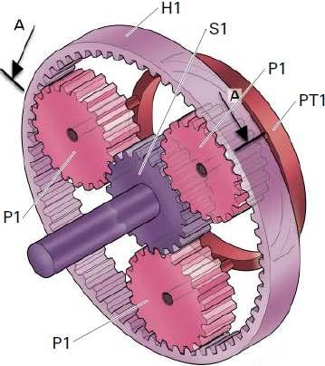
7 Automatic transmission basics Planetary gear 1. Sun gear 3. Planetary gear carrier 2. Planetary gear 4. Ring gear Planetary gear functional principles P a g e 7
8 Planetary gear transmission options P a g e 8

9 Ravigneaux - Gear 2 sun gears 1 Planetary carrier holding: 1 Ring gear 2 sets of planets. Inner and outer planet A Ravigneaux gear set is a Simple gear set on which every planet gear is replaced by an extra set of planets. Out of the 2 sets of planets only the outer set meshes the ring gear. On almost all applications the ring gear is the output component. Mathematically it adds up to 3 forward inputs of different ratio and 1 reverse motion. P a g e 9
 Ravigneaux-gear set P a g e")
10 Lepelletier -gear Front (primary) planetary gear Downstream (secondary) Ravigneaux-gear set P a g e 10

11 Shift elements multi-disc clutch Shift elements multi-disc brake P a g e 11


12 Freewheel Gearbox housing Outer ring of the freewheel Inner wheel (planetary carrier) Rolls Freewheel Locking direction Roll freewheel Clamp body freewheel P a g e 12


13 6 HP Design Sizes HP HP21 Max. Torque 400Nm HP HP28 Max. Torque 600Nm HP32 Max. Torque 750Nm P a g e 13

14 Technical description 6 forward and 1 reverse gears Electronically controlled Fixed sun single planetary gear set IN FRONT of a modified Ravigneaux gear set No OWC s Ranges weight from 170 to 220 lbs Introduction of Mechatronics Mechanical gear ratios _ P a g e 14

15 Oil pump (Crescent oil pump) The oil pump is of crescent pattern and delivers app. 16 cm3 per revolution and a pressure of 17 bar. It is located between the torque converter and the gearbox housing. The converter is supported in the pump by a needle roller bearing. The pump is directly driven by the engine via the converter shell and supplies oil to the transmission and the hydraulic control unit. The pump ingests the oil through a filter and delivers it at high pressure to the main pressure valve in the hydraulic control unit. This valve adjusts the pressure and returns excess oil back to the oil sump. P a g e 15
16 Gearbox Setting for 6 HP Automatic s P a g e 16
17 Shift elements clutch A,B and E Shift elements brake C and D P a g e 17
18 Lepelletier gear design A single planetary gear set Follow by a Ravigneaux gear set It is the heart, reason and soul of the 6HP s advantages such as lightweight, lower fuel consumption and impressive performance levels It comprises of: 2-Sun gears, 3 short planetary gears, 3 long planetary gears, 1 planetary carrier and 1 ring gear P a g e 18
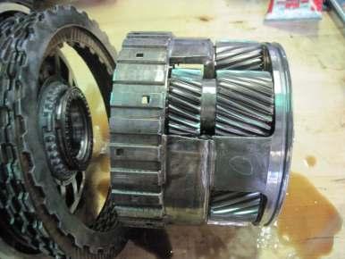
19 Lepelletier gear design P a g e 19
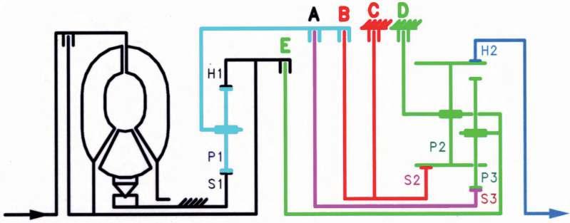
20 Systematic exposure Schematic diagram 6HP P a g e 20
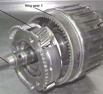
21 Description of 1st gear power flow The input shaft drives the ring gear of the front, single planetary gear set and the outer disc carrier of clutch E. Ring gear 1 drives the planet gears that roll round fixed sun gear 1. This drives planetary carrier 1 and also the outer disc carrier A as well as the inner disc carrier of clutch B. When clutch A is engaged, sun gear 3 in the Ravigneaux planetary gear set is driven. This meshes with the short planet gears. The double planetary carrier bears against the gearbox housing by way of brake D. This enables ring gear 2(output shaft) to be driven in the same direction as the engine via the long planet gears. P a g e 21
22 Description of 2nd gear power flow The input shaft drives the ring gear of the front, single planetary gear set and the outer disc carrier of clutch E. Ring gear 1 drives the planet gears that roll round fixed sun gear 1. This drives planetary carrier 1 and also the outer disc carrier A as well as the inner disc carrier of clutch B. When clutch A is engaged, sun gear 3 in the Ravigneaux planetary gear set is driven. This meshes with the short planet gears. Sun gear 2 is locked to the gearbox housing by brake C. The long planet gears which are meshed with the short planet gears roll round the fixed sun gear 2 and drive the double planetary carrier and the ring gear 2 in the direction of the engine rotation. P a g e 22
23 Description of 3rd gear power flow The input shaft drives the ring gear of the front, single planetary gear set and the outer disc carrier of clutch E. Ring gear 1 drives the planet gears that roll round fixed sun gear 1. This drives planetary carrier 1 and also the outer disc carrier A as well as the inner disc carrier of clutch B. When clutch A is engaged, sun gear 3 in the Ravigneaux planetary gear set is driven. This meshes with the short planet gears. Sun gear 2 is driven via engaged clutch B. The long planet gears which are meshed with the short planet gears cannot roll round the driven sun gear 2 and drive the blocked double planetary carrier in the direction of the engine rotation. P a g e 23
24 Description of 4th gear power flow The input shaft drives the ring gear of the front, single planetary gear set and the outer disc carrier of clutch E. Ring gear 1 drives the planet gears that roll round fixed sun gear 1. This drives planetary carrier 1 and also the outer disc carrier A as well as the inner disc carrier of clutch B. When clutch A is engaged, sun gear 3 in the Ravigneaux planetary gear set is driven. This meshes with the short planet gears. The double planetary carrier is driven via the engaged clutch E. The long planet gears which are meshed with the short planet gears drive - together with the double planetary carrier - the ring gear 2 in the direction of the engine rotation. P a g e 24
25 Description of 5th gear power flow The input shaft drives the ring gear of the front, single planetary gear set and the outer disc carrier of clutch E. Ring gear 1 drives the planet gears that roll round fixed sun gear 1. This drives planetary carrier 1 and also the outer disc carrier A as well as the inner disc carrier of clutch B. When clutch A is engaged, sun gear 3 in the Ravigneaux planetary gear set is driven. This meshes with the short planet gears. The double planetary carrier is driven via the engaged clutch E, the sun gear 2 is driven via the engaged clutch B. The long planet gears which are meshed with the short planet gears drive - together with the double planetary carrier - the ring gear 2 in the direction of the engine rotation. P a g e 25
26 Description of 6th gear power flow The input shaft drives the ring gear of the front, single planetary gear set and the outer disc carrier of clutch E. The clutches A and B are released, so that the front planetary gear set has no effect. Sun gear 2 is locked to the gearbox housing via brake C which is applied. The double planetary carrier is driven via the engaged clutch E. The long planet gears which are meshed with the short planet gears roll round the fixed sun gear 2 and drive the ring gear 2 in the direction of the engine rotation. P a g e 26
27 Description of reverse gear (R) power flow The input shaft drives the ring gear of the front, single planetary gear set and the outer disc carrier of clutch E. Ring gear 1 drives the planet gears which roll round fixed sun gear 1. This drives planetary carrier 1 and also outer disc carrier A as well as the inner disc carrier of clutch B. When clutch B is engaged, sun gear 2 in the Ravigneaux planetary gear set is driven. It is in mesh with the long planet gears. The double planetary carrier is locked to the gearbox housing by brake D. As a result ring gear 2 (output shaft) can be driven in the opposite direction to engine rotation by way of the long planet gears. P a g e 27

28 EDS Pressure regulators Do not change the composition of the valves! EDS 6 EDS 4 EDS 3 EDS 1 MV 1 EDS 5 EDS 2 P a g e 28
29 EDS-Types P a g e 29
30 Controller Matrix M-shift Position P-EDS EDS 1 EDS 2 EDS 3 EDS 5 EDS 4 MV 1 EDS 6 Responsible Clutch A Clutch B Brake C System p. Br. D & Cl. E Solenoid v. Cc Character Parking x Neutral x R-gear x st gear x x- 2nd gear x x- 3rd gear x x- 4th gear x x- 5th gear x x- 6th gear x x- Brake closed Clutch closed P a g e 30
 which are either added to or")

31 Adaption - Introduction Adaption values are corrective values (so-called offsets) which are either added to or subtracted from the default values (applied values) permanently stored in the gearbox control unit. P a g e 31

32 Adaption - Introduction Legend: n_mot = engine speed n_t = turbine speed m_mot = engine torque P_zu = pressure engaging clutch P_ab = pressure disengaging clutch t = time A, B, C = adaption phases P a g e 32
33 Adaption - Introduction Adaption of the precharge cycle (charge pressure and quick charge time) adapts clutch play and clutch resistance until the clutch assembly makes contact, but still does not transmit an appreciable amount of torque. Adaption of the shift pressure is based on an analysis of the change in gearbox input speed (engine speed gradient) during the gearshift. Example: During an excessively harsh gearshift (uncomfortable gearshift), the engine speed drops too quickly (steep engine speed gradient). The adaption program detects this condition from the engine speed gradients and reduces the clutch pressure by a defined amount (adaption value) during the next gearshift. This type of adaption is mainly carried out during the quick adaption cycle. Adaption of the holding pressure is generally based on calculations made using the values determined during the charge pressure and shift pressure adaption. P a g e 33
34 Adaption P a g e 34

35 Adaption limits P a g e 35

36 Charge pressure P a g e 36
37 Quick charge time P a g e 37
38 Adaption drive (VW / Audi) Part A Accelerate the vehicle from standing with very low throttle (15 25%) up to 4 th gear and about 80 km/h. Freewheel the car down to about 40 km/h without using the brakes. Afterwards stop the car completely and stay in drive position for about 10 s. Repeat cycle 6 times. Part B Accelerate the vehicle up to about 70 km/h und select manually 5 th gear. Use your diagnostic tool (VW/Audi block 9) to drive with 100 Nm for about 3 4 km. Accelerate the vehicle up to about 85 km/h und select manually 6 th gear. Use your diagnostic tool (VW/Audi block 9) to drive with 100 Nm for about 3 4 km. Part C Accelerate 5 times with low throttle up to about 100 km/h and freewheel the car down to about 40 km/h without using the brakes. P a g e 38
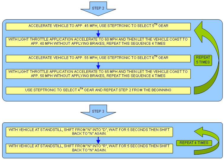
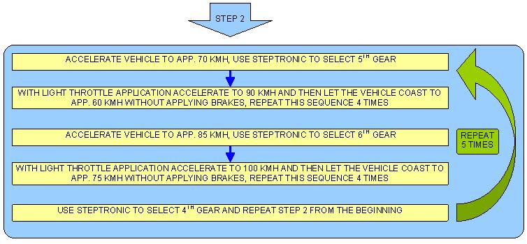
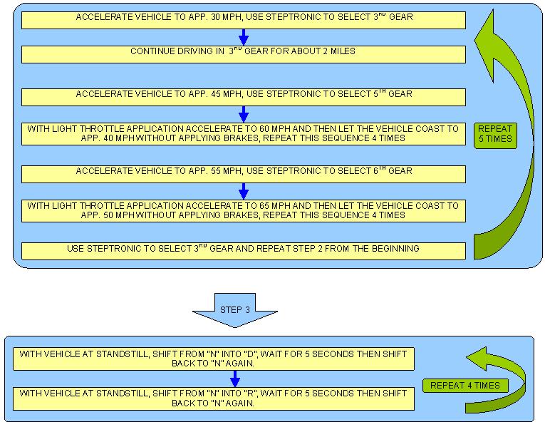
39 Adaption drive (BMW) Depending upon the production date, transmission and vehicle models, there are 4 different adaptation procedures for BMW products. Software A Software N Software P Software T (GS19.02) (GS19.04) (GS19.11) (GS19.11) 1 Series 116i /04 09/ i /04 03/ i /04 03/ d /07 now 125i GM 6 130i /04 03/ i SOP - now 3 Series 320i /05 04/ d /07 now 323i /05 09/ i /05 09/ i /07 now 5 Series /03 03/05 03/05 03/07 03/07 now 6 Series /03 09/05 09/05 09/07 09/07 now 7 Series 09/01 10/03 10/03 03/05 08/05 now X3 E /05 09/07 09/07 now X5 E /03 09/ X5 E /06 now X6 E /08 now P a g e 39

40 Adaption drive (BMW) Software A P a g e 40

41 Software N P a g e 41

42 Software P P a g e 42

43 Software T P a g e 43

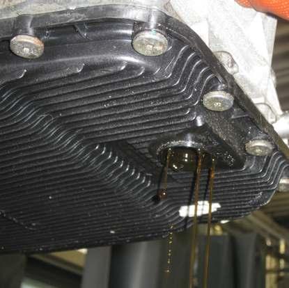
44 Drain the Oil P a g e 44
45 Removing and Attaching of the Oil Pan Remove in any order, for attaching see below. Start here to tighten the screws Attach all the screws loosely Start at Pos. 1 and Pos. 2 to tighten screws Tighten the other screws crosswise from inside to outside (positional order) Torque 10 Nm of torque for screws M6 X 28,5 P a g e 45


46 Remove the connection socket External connection socket Locking mechanism P a g e 46
47 Demounting the Mechatronic P a g e 47

48 Different Mechatronics E-Shift M-Shift P a g e 48


49 Demounting the Mechatronic Two different adapters for system pressure P a g e 49


50 Evacuate the Torque Converter P a g e 50
51 Check clutches and brakes P a g e 51
52 Dismounted Mechatronic (E shift) P a g e 52
53 Demounting the electronic module P a g e 53

54 Demounting the electronic module Guiding pins P a g e 54
55 Opening the Mechatronic P a g e 55


56 Opening the Mechatronic Rubber contamination Please clean it!!! P a g e 56

 P")
57 Position of the Check Balls (M-shift) P a g e 57

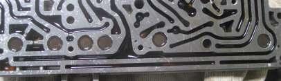
58 Opened Mechatronic Intermediate plate P a g e 58


59 Pressure regulator damper P a g e 59


60 Pressure regulator damper P a g e 60


61 Pressure regulator damper P a g e 61

62 Attach the Mechatronic to the Housing of the Gearbox M-shift When mounting the mechatronic take care of the sensor for drive position. The picture shows a not correctly installed mechanism which would cause an error in the control unit. In this condition the car will not start. P a g e 62


63 Mechatronic Tightening Sequence Torque to 8Nm 6HP19,26,32 P a g e 63


64 Mounting Connection Socket New generation Old generation Take care that the marked guide lug is mounted not exactly in vertical position For orientation use the outside of the socket were the guidance for the plug is almost in horizontal position After correct fitting close the locking mechanism carefully P a g e 64
 5HP19 5HP24 5HP30 (depending on manufacturer)")
 6HP28A61 6HP32 + X,")
65 Oil Change Lifeguard Fluid 5 (yellow-red) Used for: 5HP18 (depending on manufacturer) 5HP19 5HP24 5HP30 (depending on manufacturer) Lifeguard Fluid 6 (yellow) Used for 6HP19 6HP19X (except Audi Q7) 6HP/21/26/28 + X 6HP26A61 (except Audi W12) 6HP28A61 6HP32 + X, 6HP32A P a g e 65
 6HP28AF 8HP")


66 Lifeguard Fluid 8 (green) Used for 6HP19A 6HP19X (Audi Q7) 6HP28AF 8HP all Fill in screw BMW, Jaguar, Ford, Maserati, Hyundai, Land Rover, Aston Martin, Rolls Royce, Bentley For: 6 HP 19/19X/26/26X/32/21/28/28X P a g e 66
67 Fill in screw (Audi) Engine rpm 750 1/min Gearbox temperature between 35 and 40 Oil level control (Audi) Gearbox temperature 35 Start engine Take screw B out Screw worn No fluid coming fill up until ATF runs down P a g e 67
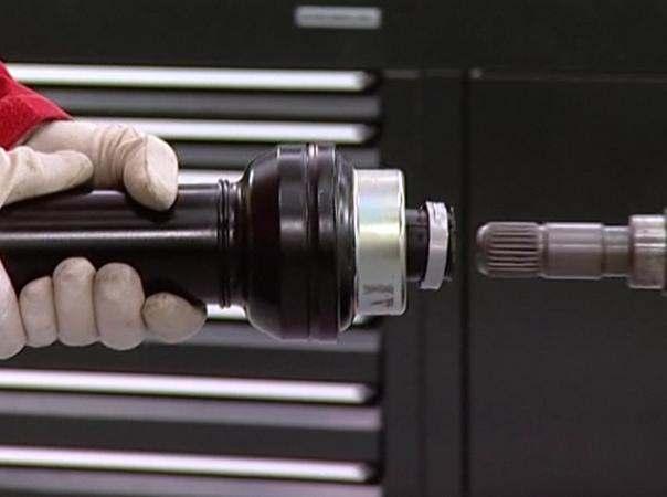
68 Bolted driveshaft P a g e 68

69 6 HP Automatic s Overhaul Overhaul - introduction Since the introduction of the 5HP series, ZF has aimed for a simplistic and streamlined design. Although the 6HP and the new 8HP series are extremely sophisticated and a technologically advanced, they are also smaller and lighter than the predecessors. The 5HP introduced a simple 3 part design: - Input, intermediate brake and output. The 6Hp is no exception. Half of the reaction components are comprised and housed within the input section. Two brakes and a Ravigneaux planetary make up the other two reaction components. P a g e 69
70 Input section Oil pump Front cover housing contains: Oil pump Torque converter stator support Single planetary s Sun gear support Oil passages for TCC apply and release P a g e 70

71 Input shaft Input shaft contains: E Clutch Passage for TCC Passage for E clutch Single planetary ring gear Turbine splines P a g e 71

72 Intermediate shaft Intermediate shaft connects: E clutch friction plates to Ravigneaux planetary carrier P a g e 72

73 Clutch A A clutch houses: Single planetary gear set carrier and planets P a g e 73

74 Sun gear shaft Sun gear shaft contains: Engages A clutch friction plates Splines into Sun Gear 3 P a g e 74

75 Disc carrier Disc Carrier contains: Meshes with clutch A drum Friction plates of clutch B P a g e 75

76 Clutch B Clutch B contains: Engages with Brake C friction plates Splines into Sun Gear 2 P a g e 76

77 Assembled Input shaft, clutch A, clutch E and Intermediate shaft assembled P a g e 77

78 Assembled Sun Gear shaft added to previous assembly P a g e 78

79 Assembled Complete Input assembly P a g e 79

80 Intermediate Brakes C and D assembly contains: C Brake D Brake Passages for C and D brakes Passage for B clutch P a g e 80
81 Output components Ravigneaux planetary gear set and D brake frictions and steels P a g e 81
82 Assembled Input assembly and intermediate assembly (C brake) P a g e 82

83 Assembled D brake and Ravigneaux planetary added to previous assembly P a g e 83

84 A Clutch disassemble Clutch A is the most unconventional assembly to disassemble. In order to remove the piston, the single planetary gear set has to be removed from the drum. Underneath the planets and towards the center of the carrier lies a snap ring that holds the planetary carrier to the drum. Push slightly towards the center and at the same time lift the carrier. P a g e 84

85 Disassemble Snap ring can be seen at the four openings in the carrier, right above the planets. P a g e 85

86 Disassemble Once the carrier is removed the tabs can be seen P a g e 86
 through input shaft s third port. Unfortunately there s only 1 Teflon ring that seals the input shaft to the pump.")
87 E clutch failure Most common fault code / failure is for E clutch. Quite often due to pressure losses at front pump bushing. Oil pressure is fed through front cover (pump) through input shaft s third port. Unfortunately there s only 1 Teflon ring that seals the input shaft to the pump. The other end of this chamber is sealed by the interference of the shaft and the bushing. As the bushing wears the clearances become too large and pressure is lost beyond the point of adaptations. P a g e 87

88 Mechatronics Separator failure More often than E clutch failure is the separator, double D, failure. Stress, heat cycles and environmental conditions causes the separator to develop small to obviously large cracks and the rubber seals at the end to shrink or get hard and brittle. Any of these conditions will cause a working or main pressure loss. These losses are reflected as adaptation faults, delayed gear engagement and, in the E Mechatronics' version, as a parking fault. Along with the separator seal, the 4 ports seals are also prone to shrinking and failure. All of these parts should be replaced. P a g e 88
89 8 HP Automatic s Modular construction system P a g e 89
90 Torque converter Sealing gearbox input shaft P a g e 90

91 ATF-Oil pump Technical data: - system pressure 5.5 to 17.5 bar - Oil delivery rate 7 to 22 l/min - Pump speed 550 to 8600 rpm P a g e 91
92 ATF-Cooling P a g e 92
 Parking brake")
 Parking brake emergency release (BMW)")
93 E-shift Mechatronic (Audi) Parking brake emergency release (Audi) Parking brake emergency release lever (Audi under driver seat) Parking brake emergency release (BMW) P a g e 93
94 Planetary Gear sets / Shift elements P a g e 94


95 Shift elements Brake B B is controlled by two pistons P a g e 95

96 Clutch C, D and E P a g e 96
97 Planetary Gear sets / Shift elements Brake A Brake B Clutch E Clutch C Clutch D P a g e 97
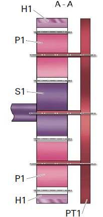
98 Gear description in 1st gear In 1st gear, internal ring gear H1 is fixed by the multidisc brake B and the double sun gear S1/S2 via the multidisc brake A against the housing (blocking position on planetary gear train RS1). The connection of the planet carrier P1 and internal ring gear H4 means that this internal ring gear is also fixed. The drive shaft provides the driving force via the closed multidisc clutch C to the sun gear S4. This drives sun gear S4 at the same speed as the turbine. The fixed internal ring gear H4 means that the planetary gears under the internal ring gear turn and drive the planet carrier P4 in the direction of engine rotation. Planet carrier P4 also acts as the output shaft. P a g e 98
99 Gear description in 2nd gear In 2nd gear, internal ring gear H1 is fixed by the multidisc brake B and the double sun gear S1/S2 via the multidisc brake A against the housing (blocking position on planetary gear train RS1). The connection of the planet carrier P1 and internal ring gear H4 means that this gear is also fixed. The drive shaft provides the driving force which drives the planet carrier P2 at the same speed as the turbine. This rolls over the fixed double sun gear S1/S2. This drives the internal ring gear H2 in the direction of engine rotation which in turn drives the sun gear S4 via the closed multidisc clutch E. The fixed internal ring gear H4 means that the planetary gears under the internal ring gear turn and drive the planet carrier P4 in the direction of engine rotation. Planet carrier P4 also acts as the output shaft. P a g e 99
100 Gear description in 3rd gear In 3rd gear the internal ring gear H1 is fixed against the housing by multidisc brake B. The drive shaft provides the driving force to the planet carrier P2 and via the closed multidisc clutch C to the sun gear S4. Both are driven at the same speed as the turbine. The closed multidisc clutch E connects sun gear S4 and internal ring gear H2 and drives them at the same speed in the direction of engine rotation (block mode on planet gear set RS2). The block position on planetary gear train RS2 means that the double sun gear S1/S2 can drive the planetary gears 1 at the same speed as the turbine which makes them roll under the fixed internal ring gear H1. This drives planet carrier P1 at lower speed in the direction of engine rotation. The fixed connection between planet carrier P1 and internal ring gear H4 produces the same direction of rotation and speed at internal ring gear H4. Sun gear S4 drives at the same speed as the turbine which means that planet carrier P4 experiences an increase in speed compared to 2nd gear. Planet carrier P4 also acts as the output shaft. P a g e 100
101 Gear description in 4th gear In 4th gear the internal ring gear H1 is fixed against the housing by multidisc brake B. The closed multidisc clutch E short circuits internal gear H3 and sun gear S3 on the planetary gear train RS3 which produces block mode on planetary gear train RS3. The closed clutch D produces a fixed connection between planet carrier P3 and the output shaft. This means that planetary gear train RS3 is driven in full at output speed in the same direction as the engine. The fixed connection of internal ring gear H3 and sun gear S4 and between sun gear S3 and internal ring gear H2 means that internal ring gear H2 and sun gear S4 are also driven at output speed. The drive shaft provides the driving force to planet carrier P2 which rolls under the internal ring gear H2 which rotates at output speed. The double sun gear S1/S2 is driven accordingly at the speed of planetary gears 2 which means that planetary gears 1 roll under the fixed internal ring gear H1 and drive the planet carrier P1 in the same direction as the engine. The planetary gear train RS4 is locked against the output shaft by the connection of the sun gear S and the planet carrier P4. This produces block mode on planetary gear train RS4. The planet carrier P1 is firmly connected to internal ring gear H4 which means that the planetary gear train is driven as a block. Planet carrier P4 also acts as the output shaft. P a g e 101
102 Gear description in 5th gear In 5th gear the internal ring gear H1 is fixed against the housing by multidisc brake B. The drive shaft provides the driving force to the planet carrier P2 and via the closed multidisc clutch C to the internal ring gear H3 and sun gear S4. Planet carrier P2, internal ring gear H3 and sun gear S4 are driven in the direction of engine rotation at the same speed as the turbine. The closed multidisc clutch D produces a fixed connection between planet carrier P3 and the output shaft. This drives the planet carrier P3 at output speed in the same direction as the engine so that it rolls under the internal ring gear H3 which is rotating at the same speed as the turbine. Sun gear S3 is driven in the opposite direction to the engine. The fixed connection between sun gear S3 and internal ring gear H2 rotates internal ring gear H2 in the opposite direction to planet carrier P2 which is driven by the drive shaft. The double sun gear S1/S2 is therefore driven in the same direction as the engine by planetary gears 2. This results in planetary gears 1 rolling under the fixed internal ring gear H1 and drive the planet carrier P1 in the same direction as the engine. Internal ring gear H4 has the same speed due to its fixed connection with planet carrier P1. This produces a speed ratio on planetary gear train RS4 between the sun gear S4 turning at the same speed as the turbine and internal ring gear H4 turning at the same speed as planet carrier P1. This speed ratio produces a resulting peripheral speed of planet carrier P4. Planet carrier P4 also acts as the output shaft. P a g e 102
103 Gear description in 6th gear The driving force from the drive shaft in 6th gear drives the closed multidisk clutches C and E. The closed multidisc clutch C initiates the propulsion of the engine into the planetary gear set. The closed multidisc clutch E short circuits internal ring gear H3 and sun gear S3. Both of these, sun gear S3 and internal ring gear H3 are driven at the same speed as the turbine which produces block mode on planetary gear train RS3. Planet carrier P3 is connected to planet carrier P4 by the closed multidisc clutch D. This results in the same speed in the same direction as the engine on planet carrier P4. Planet carrier P4 also acts as the output shaft. P a g e 103
104 Gear description in 7th gear In 7th gear the double sun gear S1/S2 is fixed against the transmission housing by the closed multidisc brake A. The drive shaft provides the driving force to the planet carrier P2 and via the closed multidisc clutch C to the internal ring gear H3. Both, planet carrier P2 and internal ring gear H3, are driven at the same speed as the turbine. As a result of driving the planet carrier P2 the planetary gears 2 roll over the fixed double sun gear S1/S2 and drive the internal ring gear H2 at the corresponding speed in the same direction as the engine. The internal ring gear H3 drives planet carrier P3 at the same speed as the turbine and sun gear S3 at a correspondingly higher speed due to the connection with internal ring gear H2. This drives the planet carrier P3 via planetary gears 3 in the same direction as the engine. Planet carrier P3 has a fixed connection with planet carrier P4 via the close multidisk clutch D which results in the same speed in the same direction as the engine at planet carrier P4. Planet carrier P4 also acts as the output shaft. P a g e 104
105 Gear description in 8th gear In 8th gear the double sun gear S1/S2 is fixed against the transmission housing by the closed multidisc brake A. Internal ring gear H3 and sun gear S3 are short circuited by the closed multidisk clutch E which produces block mode on planetary gear train RS3. The drive shaft provides the drive direct to planet carrier P2. As a result of driving the planet carrier P2 the planetary gears 2 roll over the fixed double sun gear S1/S2 and drive the internal ring gear H2 at the corresponding speed in the same direction as the engine. Internal ring gear H2 drives sun gear S3 and internal ring gear H3 via the closed multidisk clutch E (block mode on planetary gear train RS3). Planet carrier P3 has a fixed connection with planet carrier P4 via the close multidisk clutch D which results in the same speed at planet carrier P4. Planet carrier P4 also acts as the output shaft. P a g e 105
106 Gear description for reverse gear (R) In reverse gear, the ring gear H1 is secured to the transmission housing using the closed multidisc brake B, and the double sun gear S1/S2 is secured to the transmission housing using the closed multidisc brake A. The planet carrier P1 is linked with the ring gear H4 and thus is likewise secured to the housing. The planet carriers P3 and P4 are firmly linked to one another by means of the closed multidisc clutch D. Drive takes place directly from the drive shaft to the planet carrier, whereby planetary gears 2 roll onto the stationary double sun gear S1/S2 and take the internal ring gear H2 in the direction of engine rotation. The internal ring gear H2 and the sun gear S3 are firmly connected to one another. In this way, the sun gear 3 drives the internal ring gear H3 against the direction of engine rotation. The internal ring gear H3 is firmly connected with the sun gear S4, whereby the same rotational direction is achieved on sun gear S4. The sun gear S4 drives the planetary gears 4 against the direction of engine rotation, which roll beneath the stationary ring gear H4 against the direction of engine rotation and take the planet carrier P4 with them. Planet carrier P4 also acts as the output shaft. P a g e 106

107 Ratio Mechatronic E-Shift P a g e 107
108 Controller Matrix E-Shift Position P-EDS EDS 1 EDS 4 EDS 2 EDS 5 EDS 3 EDS 6 EDS 7 MV 1 Responsible Brake A Clutch D Brake B Clutch E Clutch C Cc System p. Solenoid v. Character Parking x- 0 Neutral x- 1 R-gear x- 1 1st gear x- -x- 1 2nd gear x- -x- 1 3rd gear x- -x- 1 4th gear x- -x- 1 5th gear x- -x- 1 6th gear x- -x- 1 7th gear x- -x- 1 8th gear x- -x- 1 Brake closed Clutch closed EDS-Types P a g e 108
109 Position of the Mechatronic pressure channel P a g e 109
110 Check clutches and brakes P a g e 110
111 Check clutches and brakes P a g e 111
112 Check clutches and brakes A E B1 C D B2 P a g e 112
113 Template for the tool P a g e 113

114 Parts to changing the Mechatronic Example Audi Parts needed Connection socket Oil reflux cartridge Sealing ring oil approach cartridge Sealing cartridge P a g e 114


115 Sealing oil pipes Sealing cartridge P a g e 115

116 Guiding pins for mounting the mechatronic P a g e 116

117 Oil level control Gearbox temperature 35 Start engine Take screw B out Screw worn No fluid coming fill up until ATF runs down P a g e 117
118 The hydraulic impulse oil storage HIS Mechatronic HIS Some customer-specific versions of the new generation 8-speed automatic transmission from ZF will have an integral hydraulic impulse oil storage system. This supplies hydraulic oil to the shift elements of the transmission required for starting. In turn this makes it possible to move off quickly if the engine has been stopped as required for a start-stop function. The car is ready to move away just 350 milliseconds after the engine has been started. P a g e 118
119 The hydraulic impulse oil storage HIS The HIS hydraulic impulse oil storage is a spring piston accumulator which fills with oil as the car is being driven, thus tensioning a spring. This reserve has a capacity of around 100 centiliters which is fed back into the hydraulic system lightning-quick by the spring when the engine is started to supply oil to the shift elements in the transmission required for moving away. This means that the car is ready to move away just 350 milliseconds after the engine has been started. Without the bridging created by the hydraulic impulse oil storage system this would take around 800 milliseconds which would therefore mean a perceptible loss of driving dynamics for P a g e 119
120 The hydraulic impulse oil storage HIS Solenoid not energized P a g e 120

121 Audi plugged driveshaft P a g e 121

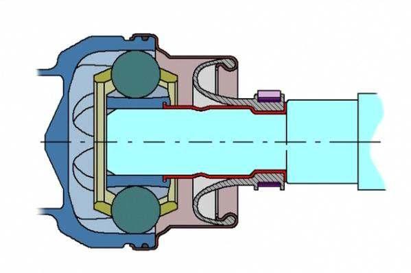
122 Audi plugged driveshaft P a g e 122
123 Vehicle for 8HP BMW group P a g e 123
124 Jaguar & Land Rover Fiat group P a g e 124
125 Volkswagen group P a g e 125
126 Identification of the P a g e 126
127 Troubleshooting While freewheeling and changing from second into first gear (for example when approaching traffic lights) a kick happens. Check play on the flex disc P a g e 127


128 4E86 MV3 Interlock fault Saved code in the ECU E 60 Prod. before 9/2005 E 60 Prod. after 9/2005 P a g e 128
129 Towing in case of breakdown Audi towing The vehicle can be towed at a maximum vehicle speed of 50 km/h over a maximum distance of 50 km using the drive wheels. The transmission must be mechanically unlocked. That means: The parking lock must be released by means of a Bowden cable. The automatic transmission can be seriously damaged if the above-mentioned boundary values are not maintained. BMW towing The precondition for towing a vehicle with an unraised drive axle is that the parking lock be opened by means of a Bowden cable emergency release. If this is the case, towing with a maximum speed of 50 km/h over a maximum distance of 50 km is possible. The automatic transmission can be seriously damaged if the above-mentioned boundary values are not maintained. Vehicles on which the parking lock must be opened with an unlocking screw cannot be towed. In case of breakdown, the vehicle must be raised with a crane and delivered to the workshop for repair on a flatbed tow truck. Four-wheel-driven vehicles Vehicles with four-wheel drive must not be towed with one axle lifted. P a g e 129
130 Pushing The engine cannot be started by pushing the vehicle. That is to say, if the engine is stopped, there is no transmission of power from the hydrodynamic coupling of the engine and transmission and the pressure-less shift elements. P a g e 130
131 P a g e 131
132 P a g e 132
LX AUTOMATIC TRANSMISSION NAG1 - SERVICE INFORMATION TABLE OF CONTENTS
 LX AUTOMATIC TRANSMISSION NAG1 - SERVICE INFORMATION 21-495 AUTOMATIC TRANSMISSION NAG1 - SERVICE INFORMATION TABLE OF CONTENTS page AUTOMATIC TRANSMISSION NAG1 - SERVICE INFORMATION DESCRIPTION...496
Module 5: Cooling Fundamentals
 Terms and Definitions Major Mechanical Parts of a Four Speed Auto Transmission Parts of a Planetary Gear System Planetary Gear System Operation Speed, Torque, and Directional Function Fluid Pump and Pressure
2007 Dodge Nitro R/T
 1 - TURBINE 2 - IMPELLER 2007 Dodge Nitro R/T CONVERTER-TORQUE DESCRIPTION TORQUE CONVERTER Fig. 267: Cutaway View Of Torque Converter Fig. 268: Impeller 2007 Dodge Nitro R/T 3 - STATOR 4 - INPUT SHAFT
 Page 1 of 10 Main Components and Functions Torque Converter 1 Cover (Part of 7902) 2 Converter Damper Plate 3 O-Ring (Part of 7902) 4 Turbine Assembly (Part of 7902) 5 Selective Spacer 6 Thrust Washer
Mercedes Presented by Dr William (Bill) Henney PhD F.I.M.I
 Henney PhD F.I.M.I") Mercedes 722.9 Presented by Dr William (Bill) Henney PhD F.I.M.I Features Electronically Controlled Automatic Gearbox 7 Forward and 2 Reverse Gears Transmission Control Module is : Integrated into the
Mercedes 722.9 Presented by Dr William (Bill) Henney PhD F.I.M.I Features Electronically Controlled Automatic Gearbox 7 Forward and 2 Reverse Gears Transmission Control Module is : Integrated into the
Amarok 2012 The 8-speed automatic gearbox 0CM Design and function
 Service Training Commercial Vehicles Self-Study Programme Technology 507 Amarok 2012 The 8-speed automatic gearbox 0CM Design and function The 8-speed automatic gearbox in the Amarok With a combustion
ASSEMBLY. Transmission Automatic Transaxle/Transmission. Special Tool(s) Alignment Set, Fluid Pump 307-S039 (T74P X) Special Tool(s)
 Alignment Set, Fluid Pump 307-S039 (T74P X) Special Tool(s)") 307-01-1 Automatic Transaxle/Transmission 307-01-1 ASSEMBLY Transmission Special Tool(s) Adjustment Set, Transmission Band 307-S022 (T71P-77370-A) Special Tool(s) Alignment Set, Fluid Pump 307-S039 (T74P-77103-X)
307-01-1 Automatic Transaxle/Transmission 307-01-1 ASSEMBLY Transmission Special Tool(s) Adjustment Set, Transmission Band 307-S022 (T71P-77370-A) Special Tool(s) Alignment Set, Fluid Pump 307-S039 (T74P-77103-X)
ZF Transmissions with Mechatronics
 ZF Transmissions with Mechatronics Hans-Peter Bach, Director Serivce (hans-peter.bach@zf.com) ZF Getriebe GmbH, Business Unit Automatic Transmissions mbh, 2006 ZF Getriebe Gm Topics Business unit Automatic
Service Training Edition Speed Automatic Gearbox 09A/09B. Trainer Information (GB)
") 7.02 Edition 09.2000 5-Speed Automatic Gearbox 09A/09B Trainer Information (GB) Contents Section Page General Information 2 Input and output signals 7 Control System Details 9 ATF Pressure Control 16 Lock-up
7.02 Edition 09.2000 5-Speed Automatic Gearbox 09A/09B Trainer Information (GB) Contents Section Page General Information 2 Input and output signals 7 Control System Details 9 ATF Pressure Control 16 Lock-up
AUTOMATIC TRANSMISSIONS Mitsubishi F3A20 Series TRANSMISSION APPLICATION TABLE
 Article Text ARTICLE BEGINNING AUTOMATIC TRANSMISSIONS Mitsubishi F3A20 Series APPLICATION TRANSMISSION APPLICATION TABLE Vehicle Application Transmission Model Colt 3-Speed (1990-94)... F3A21 Colt Vista
 Page 1 of 22 SECTION 307-01: Automatic Transaxle/Transmission 4R70E/4R75E ASSEMBLY Procedure revision date: 05/29/2009 Transmission Printable View (1554 KB) Special Tool(s) Air Test Plate, Transmission
TION AND OPERATION Procedure revision date: 01/22/1999
 TION AND OPERATION Procedure revision date: 01/22/1999 Main Components and Functions AX4S Main Components http://www.fordtechservice.dealerconnection.com/pubs/content/~wsww/~mus~len/20/sww71006.htm (1
ZF 6HP26 Automatic Transmission Component Location
 Published : Apr 8, 2005 ZF 6HP26 Automatic Transmission Component Location Item Part Number Description 1 - PRND LCD display 2 - M/S LCD display 3 - Selector lever assembly 4 - Instrument cluster 5 - Automatic
ASSEMBLY. Transmission Automatic Transmission 5R44E and 5R55E. Special Tool(s)
") 307-01-1 Automatic Transmission 5R44E and 5R55E 307-01-1 ASSEMBLY Transmission Special Tool(s) Holding Fixture, Transmission 307-262 (T93T-77002-AH) Special Tool(s) Installer, Transmission Extension Housing
307-01-1 Automatic Transmission 5R44E and 5R55E 307-01-1 ASSEMBLY Transmission Special Tool(s) Holding Fixture, Transmission 307-262 (T93T-77002-AH) Special Tool(s) Installer, Transmission Extension Housing
chart for this unit. Let s look at some of the gear
 by David Skora recently began seeing a new 6- speed automatic transmission in some Beetle and Passat vehicles. Built by Aisan, this transmission uses the Leppeletier planetary design. All shift timing
ZF 6HP26A 61 6HP26A 61. Automatic Transmission Spare Parts Catalog
 ZF 6HP26A 61 6HP26A 61 Automatic Transmission Spare Parts Catalog Warranty Information Warranty coverage for ZF passenger car transmission spare parts and kits covers the first 12 months after installation
Advanced Auto Tech Worksheet Auto Trans & Transaxle Chapter 40 Pages Points Due Date
 Advanced Auto Tech Worksheet Name Auto Trans & Transaxle Chapter 40 Pages 1173 1215 107 Points Due Date 1. Automatic transmissions are operated by hydraulics as well as electronics to select according
6-Speed Automatic Transmission 09G/09M Design and Function
 6-Speed Automatic Transmission 09G/09M Design and Function Self-Study Program Course Number 851503 Volkswagen of America, Inc. Service Training Printed in U.S.A. Printed 04/05 Course Number 851503 2005
5-speed Automatic Gearbox 09A/09B
 Service. Self-Study Programme 232 5-speed Automatic Gearbox 09A/09B Design and Function The new 5-speed automatic gearbox The new automatic gearbox is intended for installation in the Volkswagen and Audi
6-speed Automatic Gearbox 09G/09K/09M
 Service Training Self-study Programme 309 6-speed Automatic Gearbox 09G/09K/09M The 6-speed automatic gearbox from the Japanese manufacturer AISIN is used in the following Volkswagen vehicles: Code Maximum
ZF 6HP26X / 6HP28X 6HP26X 6HP28X. Automatic Transmission Spare Parts Catalog
 ZF 6HP26X / 6HP28X 6HP26X 6HP28X Automatic Transmission Spare Parts Catalog Warranty Information Warranty coverage for ZF passenger car transmission spare parts and kits covers the first 12 months after
Shift Solenoid B (SSB) and Shift Solenoid D (SSD) Inverse Proportional VFS 2761
 and Shift Solenoid D (SSD) Inverse Proportional VFS 2761") Item Description 1 Shift Solenoid A (SSA) Variable Force Solenoid (VFS) 2 Shift Solenoid C (SSC) VFS SSB and SSD use inverse proportional operation. As the current from the PCM decreases, the pressure
Item Description 1 Shift Solenoid A (SSA) Variable Force Solenoid (VFS) 2 Shift Solenoid C (SSC) VFS SSB and SSD use inverse proportional operation. As the current from the PCM decreases, the pressure
Automatic Transmission Basics
 Section 1 Automatic Transmission Basics Lesson Objectives 1. Describe the function of the torque converter. 2. Identify the three major components of the torque converter that contribute to the multiplication
AUTOMATIC TRANSMISSION (5AT)
") (5AT) GENERAL 1. General To improve the dynamic performance and fuel efficiency of the vehicle, a new 5-speed automatic transmission is developed. The features of this new automatic transmission are as
(5AT) GENERAL 1. General To improve the dynamic performance and fuel efficiency of the vehicle, a new 5-speed automatic transmission is developed. The features of this new automatic transmission are as
GA6HP26Z Automatic Transmission Objectives of the Module...1 Purpose of the System...2 Technical Data...5
 Table of Contents Subject Page Objectives of the Module.....................................1 Purpose of the System.......................................2 Technical Data.............................................5
DRIVETRAIN 7.0 Introduction 7.1 Drivetrain configurations 7.2 Drivetrain elements 7.3 Clutch Operation
 DRIVETRAIN 7.0 Introduction Drivetrain is the assembly of all the components that are involved in the transmission of the power from the engine of the vehicle to its wheels. 7.1 Drivetrain configurations
ZF 6HP26 / 6HP28 6HP26 6HP28. Automatic Transmission Spare Parts Catalog
 ZF 6HP26 / 6HP28 6HP26 6HP28 Automatic Transmission Spare Parts Catalog Warranty Information Warranty coverage for ZF passenger car transmission spare parts and kits covers the first 12 months after installation
Pull out clutch E snap ring and withdraw complete clutch pack of clutch E. 6 HP 26 ZF Getriebe GmbH Saarbrücken CD
 Press down cup spring in the mandrel press with assembly bracket 5x46 002 566 and remove snap ring with suitable pliers. Take out planet carrier and cup spring. Take the O-ring seal off the planet carrier.
Assembly. NOTE: Before beginning assembly, perform/inspect the following:
 Page 1 of 31 Home Account Contact ALLDATA Log Out Help DAN GRIMWOOD DAN GRIMWOOD00002 Select Vehicle New TSBs Technician's Reference Component Search: OK 1997 Ford Truck F 150 2WD Pickup V6-4.2L VIN 2
DC 5-SPEED AUTOMATIC TRANSMISSION
 03 1. OVERVIEW 2WD 4WD DCAG 5speed automatic transmission is an electronically controlled 5speed transmission with a lockup clutch in the torque converter. The ratios for the gears are realized by three
Continuously Variable Transaxle Specification. Forward/Reverse Switching Mechanism Double Pinion Type Planetary Gear
 CVT SYSTEM > GENERAL OUTLINE 1. A newly developed K41A Continuously Variable Transaxle (CVT) is used for the1kr-fe engine models. 2. The K41A CVT, including a pair of the pulleys and the belt in the shift
2002 F-Super Duty /Excursion Workshop Manual
 Page 1 of 25 SECTION 307-01: Automatic Transaxle/Transmission 2002 F-Super Duty 250-550/Excursion Workshop Manual ASSEMBLY Procedure revision date: 05/23/2001 Transmission Special Tool(s) Remover, O-Ring
Geo Prizm ( LSi) Toyota Celica 1.8L (1994)
 Toyota Celica 1.8L (1994)") Page 1 of 140 ARTICLE BEGINNING APPLICATION TRANSMISSION APPLICATIONS Application Geo Prizm (1993-94 LSi) Toyota Celica 1.6L (1993) Celica 1.8L (1994) Celica 2.2L (1993) Corolla 1.8L MR2 Paseo Transaxle
Page 1 of 140 ARTICLE BEGINNING APPLICATION TRANSMISSION APPLICATIONS Application Geo Prizm (1993-94 LSi) Toyota Celica 1.6L (1993) Celica 1.8L (1994) Celica 2.2L (1993) Corolla 1.8L MR2 Paseo Transaxle
Oil change kit for ZF 5HP/6HP automatic transmission
 Risk of burns due to contact with hot oil. Slight to moderate injury possible. Wear protective goggles. Wear protective gloves. Wear protective clothing. Property damage due to electrostatic discharge
FORD 6R80 UPDATES Presented by: David Chalker ATRA Technical Advisor 6R80
 FORD UPDATES Presented by: David Chalker ATRA Technical Advisor Welcome To Today s Presentation Sponsored By: Any Questions Or Comments Please Send Emails To webinars@atra.com Any Questions That You
DISASSEMBLY. Transmission. All vehicles
 307-01-1 Automatic Transmission 5R44E and 5R55E 307-01-1 DISASSEMBLY Transmission Special Tool(s) Holding Fixture, Transmission 307-262 (T93T-77002-AH) Special Tool(s) Remover, Servo 307-347 (T97T-7D021-A)
ZF 6HP19X / 6HP21X 6HP19X 6HP21X. Automatic Transmission Spare Parts Catalog
 ZF 6HP19X / 6HP21X 6HP19X 6HP21X Automatic Transmission Spare Parts Catalog Warranty Information Warranty coverage for ZF passenger car transmission spare parts and kits covers the first 12 months after
2003 E-Series Workshop Manual
 Page 1 of 20 SECTION 307-01B: Automatic Transmission 4R70W 2003 E-Series Workshop Manual ASSEMBLY Procedure revision date: 04/27/2006 Transmission Printable View (1828 KB) Special Tool(s) Dial Indicator
Continuously Variable Transaxle Specification. Forward/Reverse Switching Mechanism Double Pinion Type Planetary Gear
 CVT SYSTEM > GENERAL OUTLINE 1. A newly developed K41B Continuously Variable Transaxle (CVT) is used for the1nr-fe engine models. 2. The K41B CVT, including a pair of the pulleys and the belt in the shift
CHASSIS AUTOMATIC TRANSAXLE. Destination New Model Previous Model Change (from previous model)
") CHASSIS AUTOMATIC TRANSAXLE CH-37 U341E AUTOMATIC TRANSAXLE 1. General The compact and high-capacity 4-speed U341E automatic transaxle [Super ECT (Electronic Controlled Transaxle)] is used. The following
CHASSIS AUTOMATIC TRANSAXLE CH-37 U341E AUTOMATIC TRANSAXLE 1. General The compact and high-capacity 4-speed U341E automatic transaxle [Super ECT (Electronic Controlled Transaxle)] is used. The following
6-speed automatic transmission E60, E53. VS-22 je Baugruppe/Group: (040) 09/2003. Introduction
 09/2003. Introduction") VS-22 je Baugruppe/Group: 24 24 01 03 (040) 6-speed automatic transmission E60, E53 weltweit Datum/Date: 09/2003 Introduction The 6-speed automatic transmissions GA6HP19Z and GA6HP26Z have been jointly
VS-22 je Baugruppe/Group: 24 24 01 03 (040) 6-speed automatic transmission E60, E53 weltweit Datum/Date: 09/2003 Introduction The 6-speed automatic transmissions GA6HP19Z and GA6HP26Z have been jointly
TORQUE CONVERTER. Section 2. Lesson Objectives. 6 TOYOTA Technical Training
 Section 2 TORQUE CONVERTER Lesson Objectives 1. Describe the function of the torque converter. 2. Identify the three major components of the torque converter that contribute to the multiplication of torque.
U340E AND U441E AUTOMATIC TRANSAXLES
 ASSIS U340E AND U441E AUTOMATIC TRANSAXLES -41 U340E AND U441E AUTOMATIC TRANSAXLES DESCRIPTION The new model uses 2 types (U340E, U441E) of automatic transaxle. A U340E automatic transaxle is provided
Table of Contents. E70 Transmissions
 Table of Contents Subject Page New Transmissions for E70....................................5 Changes.......................................................5 Technical Data...............................................6
REPAIR MANUAL. Version 02/11/01 CD ZF GETRIEBE GMBH SAARBRÜCKEN
 REPAIR MANUAL 6 HP-26 Version CD ZF GETRIEBE GMBH SAARBRÜCKEN subject to alterations Copyright 2002 all rights reserved and published by ZF Getriebe GmbH, Saarbrücken, Department MKTD No part of this manual
ELECTRONIC CONTROL SYSTEM. 1. General CH-16 CHASSIS - U340E AUTOMATIC TRANSAXLE
 CH-16 ELECTRONIC CONTROL SYSTEM 1. General The electronic control system of the U340E automatic transaxle consists of the controls listed below. System Clutch Pressure Control (See page CH-20) Line Pressure
Rear Drive Axle and Differential
 Page 1 of 13 Rear Drive Axle and Differential GENERAL Item Part Number Description A - Electronic rear differential B - Open rear differential 1 - Rear driveshaft 2 - Electronic rear differential 3 - RH
2005 Toyota RAV AUTOMATIC TRANSMISSIONS U240E & U241E Overhaul
 2001-05 AUTOMATIC TRANSMISSIONS U240E & U241E Overhaul APPLICATION CAUTION: Flush oil cooler and oil cooler lines prior to transaxle installation. Oil cooling system contamination may cause premature transaxle
AUTOMATIC TRANSMISSIONS. General Motors Corp. Hydra-Matic 4L60-E Overhaul
 1997-98 AUTOMATIC TRANSMISSIONS General Motors Corp. Hydra-Matic 4L60-E Overhaul APPLICATION TRANSMISSION APPLICATIONS Application Corvette Transaxle 4L60-E IDENTIFICATION The 4L60-E transmission can be
4T80E. FWD 4 Speed Primary/Secondary Pump. 2-3 Accum. Valve Body Cover Channel Plate Upper Valve Body.
 4T80E FWD 4 Speed 2 190 A 191 54 55 250 Valve Body Cover 156 Primary/Secondary Pump 155 129 151 152 157 3 Upper Valve Body 2-3 Accum. 183 53 182 Channel Plate 20 21 60 135 91 195 72 73 B 33 2nd Clutch
OPERATION FIRST GEAR POWERFLOW TJ - JEEP WRANGLER - 4.0L 6 CYL (MPI) 21 - Transmission and Transfer Case/Automatic - 42RLE/Operation
 21 - Transmission and Transfer Case/Automatic - 42RLE/Operation") 2006 - TJ - JEEP WRANGLER - 4.0L 6 CYL (MPI) 21 - Transmission and Transfer Case/Automatic - 42RLE/Operation OPERATION The 42RLE transmission ratios are: GEAR RATIO First 2.84 : 1 Second 1.57 : 1 Third
2006 - TJ - JEEP WRANGLER - 4.0L 6 CYL (MPI) 21 - Transmission and Transfer Case/Automatic - 42RLE/Operation OPERATION The 42RLE transmission ratios are: GEAR RATIO First 2.84 : 1 Second 1.57 : 1 Third
DC-5 SPEED AUTOMATIC TRANSMISSION
 01-3 DC-5 SPEED AUTOMATIC TRANSMISSION GENERAL 1. SPECIFICATIONS 01-4 01-5 OVERVIEW AND OPERATION PROCESS 1. OVERVIEW 2WD 4WD DC 5-Speed Automatic Transmission DCAG 5-speed automatic transmission is an
Transmissions. Service Training Course No. 200 WARNING: WHILE SERVICING AND TESTING VEHICLES AND VEHICLE SYSTEMS, TAKE ALL
 Service Training Course No. 200 Transmissions This publication is intended for instructional purposes only. Always refer to the appropriate Jaguar Service publication for specific details and procedures.
Direct Clutch Assembly 1263
 SECTION 307-01: Automatic Transaxle/Transmission 2006 F-53 Motorhome Chassis TorqShift Workshop Manual DISASSEMBLY AND ASSEMBLY OF SUBASSEMBLIES Procedure revision date: 11/29/2004 Direct Clutch Assembly
MANUAL TRANSAXLE SECTIONMT CONTENTS IDX. Shift Control Components...34
 MANUAL TRANSAXLE SECTIONMT GI MA EM LC EC CONTENTS FE PREPARATION...3 Special Service Tools...3 Commercial Service Tools...5 NOISE, VIBRATION AND HARSHNESS (NVH) TROUBLESHOOTING...6 NVH Troubleshooting
2001 Chevrolet Corvette AUTOMATIC TRANSMISSIONS Hydra-Matic 4L60-E - Overhaul
 2001-03 AUTOMATIC TRANSMISSIONS Hydra-Matic 4L60-E - Overhaul APPLICATION CAUTION: Flush oil cooler and oil cooler lines prior to transmission installation. Oil cooling system contamination may cause premature
Transaxle. 1. Mount the transaxle to Bench Mounted Holding Fixture T57L-500-B.
 «1997 Aspire Table of Contents» «Group 07: TRANSAXLE» «Section 07-01: Transaxle, Automatic» «DISASSEMBLY» Transaxle CAUTION: To prevent dirt from entering the transaxle, it should be disassembled and kept
11.AWD Transfer System
 W1860BE.book Page 54 Tuesday, January 28, 2003 11:01 PM 11.AWD Transfer System A: MPT MODELS 1. GENERAL This all-wheel-drive (AWD) transfer system uses an electronically controlled multi-plate type transfer
FOREWORD ALPHABETICAL INDEX
 FOREWORD I This manual is a guide and a reference book to be used in the proper servicing of the Hudson Automatic Transmission. The procedures covering: Operation, testing, diagnosis, adjustments, removal,
Description. Cooling. Mechatronik module. Automatic Transmission (07.01) Transmission (07.00) transmission fault-finding.
 Transmission (07.00) transmission fault-finding.") Automatic Transaxle (07.01) Description The ZF 6HP26 automatic gearbox has the following features: Six forward speeds and One reverse A torque converter with an integral converter lock-up clutch Electronic
Automatic Transaxle (07.01) Description The ZF 6HP26 automatic gearbox has the following features: Six forward speeds and One reverse A torque converter with an integral converter lock-up clutch Electronic
Welcome To Today s Presentation Sponsored By:
 Welcome To Today s Presentation Sponsored By: Any Questions Or Comments Please Send Emails To webinars@atra.com Any Questions That You May Have During The Webinar Please Feel Free To Text Them In At Any
Automatic Transmissions & Transaxles
 ATASA 5 th Study Guide Chapter 40 Pages 1173 1215 Automatic Transmissions /Transaxles 107 Points Be Certain to Read the Summary 1. Automatic transmissions are operated by hydraulics as well as electronics
REPAIR MANUAL 5 HP - 30 ZF GETRIEBE GMBH SAARBRÜCKEN
 REPAIR MANUAL 5 HP - 30 ZF GETRIEBE GMBH SAARBRÜCKEN Impressum: Verantwortlich für den Inhalt Abteilung MKTD, ZF Getriebe GmbH, Saarbrücken Druck: HAGER PAPPRINT GmbH, Gedruckt in der BRD Published by
Transmission Description
 Page 1 of 23 Published: Feb 1, 2007 Transmission Description COMPONENT LOCATION Item Part Number Description 1 Transmission selector lever assembly 2 Cable bracket 3 Automatic transmission 4 Transmission
DISASSEMBLY AND ASSEMBLY
 307-01-1 Automatic Transaxle/Transmission 307-01-1 DISASSEMBLY AND ASSEMBLY Transaxle Special Tool(s) Dial Indicator Gauge With Holding Fixture 100-002 (TOOL-4201-C) Special Tool(s) Test Plate Screw Set,
FUNDAMENTALS OF AUTOMATIC TRANSMISSIONS
 Section 1 FUNDAMENTALS OF AUTOMATIC TRANSMISSIONS Lesson Objectives 1. Compare the function of automatic transmission systems of front- and rear-wheel drive transmissions. 2. List the three major component
TRANSMISSION PARTS Instructions. Solenoid Regulator Valve Retainer Shim. Main Pressure Regulator Valve
 TRANSMISSION PARTS Instructions Sure Cure Kit Part No. SC-AODE NOTE: This kit is fully compatible with '91 '95 only. Identified by alignment pins 13mm heads. This kit will not work on '96 Later units.
SECTION : Automatic Transmission
 307-01-1 Automatic Transmission 307-01-1 SECTION : 307-01 Automatic Transmission VEHICLE APPLICATION : 2003.0 BA Falcon CONTENTS SPECIFICATIONS PAGE Specifications...307-01-3 DESCRIPTION AND OPERATION
Cars Drivetrain 9-Speed Automatic Transmission (725.0) AKUBIS direct special Final Test Go Hand-outs for participants
 AKUBIS direct special Final Test Go Hand-outs for participants") Global Training The finest automotive learning Cars Drivetrain 9-Speed Automatic Transmission (725.0) AKUBIS direct special Final Test Go Hand-outs for participants T0831E As at 06.09.2013 This document
Global Training The finest automotive learning Cars Drivetrain 9-Speed Automatic Transmission (725.0) AKUBIS direct special Final Test Go Hand-outs for participants T0831E As at 06.09.2013 This document
AODE ( 96 & LATER) SC-AODE-1. Transmission Reconditioning Kit FULL COMPATIBILITY IMPORTANT VALVE BODY PARTS REASSEMBLY PARTS
 SC-AODE-1. Transmission Reconditioning Kit FULL COMPATIBILITY IMPORTANT VALVE BODY PARTS REASSEMBLY PARTS") AODE ( 96 & LATER) Transmission Reconditioning Kit FULL COMPATIBILITY SC-AODE-1 Full compatibility with 1996 and later units. Identified by alignment pins with 10mm head and.173" pin diameter. IMPORTANT
AODE ( 96 & LATER) Transmission Reconditioning Kit FULL COMPATIBILITY SC-AODE-1 Full compatibility with 1996 and later units. Identified by alignment pins with 10mm head and.173" pin diameter. IMPORTANT
MANUAL TRANSMISSION SERVICE
 MANUAL TRANSMISSION SERVICE Introduction Internal combustion engines develop very little torque or power at low rpm. This is especially obvious when you try to start out in direct drive, 4th gear in a
Jatco 5 Speed ATRA. All Rights Reserved. Printed in U.S.A.
 1 2 3 Table Of Contents Transmission Diassembly... 4 Front Pump... 16 Reverse/High Clutch Drum... 18 Direct Clutch Drum... 22 Low Clutch Drum... 26 Planetary Gearsets... 29 Transfer Gear/Reduction Gear...
CONTINUOUSLY VARIABLE TRANSMISSION (CVT)
") 23-1 GROUP 23 CONTINUOUSLY VARIABLE TRANSMISSION () CONTENTS........................... 23-2 GENERAL INFORMATION............. 23-2 PRINCIPLE OF IMPROVEMENTS IN FUEL ECONOMY AND PERFORMANCE WITH......................................
23-1 GROUP 23 CONTINUOUSLY VARIABLE TRANSMISSION () CONTENTS........................... 23-2 GENERAL INFORMATION............. 23-2 PRINCIPLE OF IMPROVEMENTS IN FUEL ECONOMY AND PERFORMANCE WITH......................................
ASSEMBLY PROCEDURE. Transmission
 67 ASSEMBLY PROCEDURE Transmission Tools Required 0555-336256 Transmission Bench Cradle 0555-336258 Cross Shaft Pin Remover/Installer (Detent Lever) 0555-336262 Cross Shaft Seal Installer 0555-336263 Cross
3 Axles and brakes. 3.1 Function and construction of the axles Construction Function
 3 Axles and brakes 3.1 Function and construction of the axles 3.1.1 Function Each wheel has an independent suspension system in the axle body (1), so that individual wheel suspension is provided. The swinging
Dismantling and assembling automatic transmission (A5S560Z) (transmission removed)
 (transmission removed)") 24 00 585 Dismantling and assembling automatic transmission (A5S560Z) (transmission removed) Secure transmission to assembly frame with special tool 24 0 180. Drain off transmission oil. Screw special
24 00 585 Dismantling and assembling automatic transmission (A5S560Z) (transmission removed) Secure transmission to assembly frame with special tool 24 0 180. Drain off transmission oil. Screw special
SECTION ZF TRANSMISSION
 10-103.04/ 1 2009JL16 SECTION 10-103.04 GENERAL DESCRIPTION See Figure 1. The ZF-Ecomat transmission consists of a hydrodynamic torque converter, with a lock-up clutch for direct drive, a hydrodynamic
ASSEMBLY PROCEDURE AUTOMATIC TRANSMISSION 5A-173. Transmission
 AUTOMATIC TRANSMISSION 5A-173 ASSEMBLY PROCEDURE Transmission Tools Required 0555-336256 Transmission Bench Cradle 0555-336258 Cross Shaft Pin Remover/Installer (Detent Lever) 0555-336262 Cross Shaft Seal
HAKO cut-away models. 10: Clutches, Transmission, Automatic Transmission, Rear-wheel Drive, Front-wheel Drive, Steering, Chassis, Damping, Suspension
 10: Clutches, Transmission, Automatic Transmission, Rear-wheel Drive, Front-wheel Drive, Steering, Chassis, Damping, Suspension Order No. 1211 Clutch functional model A diaphragm spring clutch is mounted
2011 Dodge or Ram Truck RAM 3500 Truck 4WD L6-6.7L DSL Turbo
 1 of 10 10/14/2013 9:23 AM 2011 Dodge or Ram Truck RAM 3500 Truck 4WD L6-6.7L DSL Turbo Vehicle» A L L Diagnostic Trouble Codes ( DTC )» Testing and Inspection» P Code Charts» P0732 P0732-GEAR RATIO ERROR
70001 and Clutch Rebuild Instructions
 70001 and 70010 Clutch Rebuild Instructions Brinn, Incorporated 1615 Tech Drive Bay City, MI 48706 Telephone 989.686.8920 Fax 989.686.6520 www.brinninc.com Notice Use these instructions if you only want
ZF 6HP19 Automatic Transmission - Available Spare Parts (REFERENCE ONLY*)
") 6 HP 19 - GEARBOX HOUSING 6 HP 19 A HOUSING 6 HP 19 X - GEARBOX HOUSING Pos.# Pos.# Pos.# Part # Description 01.080 01.080 01.080 0501 314 809 01 VENT COVER 0501 314 809 01 VENT COVER 0501 314 851 01 BREATHER
6 HP 19 - GEARBOX HOUSING 6 HP 19 A HOUSING 6 HP 19 X - GEARBOX HOUSING Pos.# Pos.# Pos.# Part # Description 01.080 01.080 01.080 0501 314 809 01 VENT COVER 0501 314 809 01 VENT COVER 0501 314 851 01 BREATHER
Automatic Gearbox - Fundamentals -
 Automatic Gearbox - Fundamentals - The gearbox in a motorcar is the technical aid for converting the engine forces into the varying operating conditions. Operating the clutch and shifting gears make up
In the last issue of GEARS we went
 A Look Inside the 6-Speed Volkswagen Automatic; Part 2 A Look Inside the 6-Speed Volkswagen Automatic; Part 2 by David Skora In the last issue of GEARS we went over the theory of VW s 09G and 09M 6-speed
U140E AND U241E AUTOMATIC TRANSAXLE
 CH-125 U140E AND U241E AUTOMATIC TRANSAXLE DESCRIPTI The 02 Camry line-up uses the following types of automatic transaxles: 2AZ-FE U241E 1MZ-FE U140E These automatic transaxles are compact and high-capacity
23. Planetary Gear and Low Clutch S510212
 Automatic Transmission 23. Planetary Gear and Low Clutch S510212 A: REMOVAL S510212A18 1) Extract the torque converter clutch assembly. 2) Remove
1 of 25 9/12/2013 9:07 PM
 1 of 25 9/12/2013 9:07 PM 46RE Automatic Transmission DISASSEMBLY 1. Clean exterior of transmission with suitable solvent or pressure washer. 2. Place transmission in vertical position. 3. Measure the
4T65E 1997-Up. Power Flow Chart
 4T65E 1997-Up Bearing MN 7 M15/MN3 Bushing Sol. Sol. Input Second Third Fourth Fwd. D-2 Rev. Input 1-2 3RD A B Clutch Clutch Clutch Clutch Band Band Band Sprag Roller Sprag Park/ On* On* Neutral On On
AUTOMATIC TRANSAXLE AUTOMATIC TRANSAXLE SYSTEM... COMPONENT PARTS...
 SYSTEM....... COMPONENT PARTS.................... OIL PUMP.............................. DIRECT CLUTCH........................ FORWARD CLUTCH..................... SECOND BRAKE........................ UNDERDRIVE
TRANSMISSION PARTS BOOK
 TRANSMISSION PARTS BOOK SS-6, SS-636, SS-836 SS-8, SS-08 DATE: 7-3-96 CLARK 8000 SERIES INTERMEDIATE DROP BARAGA PRODUCTS, INC. 55 N. Superior Ave. Baraga, MI 9908-08 Ph. (906) 353-6675 Fax (906) 353-75J
JF506E (JA5A-EL/5F31J/RE5F01A/09A)
") FWD 5 Speed FWD 5 Speed 750 699 284 730 281 712 281 796 282 280 869 283 586 596 868 616 864 866 142 561 961 331 981 865 971 330 122 551 040 257 862 650 180 260 261 259 022 790 A A 698 715 077 293* 292
FWD 5 Speed FWD 5 Speed 750 699 284 730 281 712 281 796 282 280 869 283 586 596 868 616 864 866 142 561 961 331 981 865 971 330 122 551 040 257 862 650 180 260 261 259 022 790 A A 698 715 077 293* 292
GM 4L80-E, 4L85-E SURE CURE KIT
 GM 4L80-E, 4L85-E SURE CURE KIT PART NUMBER SC-4L80E INSTALLATION GUIDE Parts are labeled here in order of installation. See page 2 for details on Sure Cure kit contents. See Sure Cure instruction booklet
6-speed automatic transmission 09D
 Service. Self-Study Programme 300 6-speed automatic transmission 09D Design and function Compared to the 5-speed automatic transmission, the 09D 6-speed automatic transmission provides: a reduction in
ABBREVIATIONS USED IN THIS
 IN10 INTRODUCTION ABBREVIATIONS USED IN THIS MANUAL ABBREVIATIONS USED IN THIS MANUAL ATF Automatic Transmission Fluid B 0 Overdrive Brake B 2 Second Brake B 3 No. 3 Brake C 0 Overdrive Direct Clutch C
6-speed manual gearbox 0A5
 Service Training Self-study programme 320 6-speed manual gearbox 0A5 Design and function S320_002 In addition to meeting increasing technical demands, modern cars also have to represent effective space
RF80C-76G9 RF80M-77K5
 Publication No. W561-0201E 01 Torque converter Transmission Model RF80C-76G9 RF80M-77K5 Foreword Foreword This service manual gives the disassembly and reassembly procedures for torque converters and transmissions
GM 4L80-E, 4L85-E SURE CURE KIT
 GM 4L80-E, 4L85-E SURE CURE KIT PART NUMBER SC-4L80E INSTRUCTION BOOKLET Parts are labeled here in order of installation. See page 2 for details on Sure Cure kit contents. See Sure Cure instruction booklet
2012 NATEF Task Area A 2 Automatic Transmission
 2012 NATEF Task Area A 2 Automatic Transmission A. General Transmission & Transaxle Diagnosis B. Transmission & Transaxle Maintenance & Adjustment C. In Vehicle Transmission & Transaxle Repair D. Off Vehicle
Unit V HYDROSTATIC DRIVE AND ELECTRIC DRIVE
 Unit V HYDROSTATIC DRIVE AND ELECTRIC DRIVE HYDROSTATIC DRIVE In this type of drives a hydrostatic pump and a motor is used. The engine drives the pump and it generates hydrostatic pressure on the fluid.
Toyota A750 E/F A760 E/F A761 Introduction. Sponsored By: Presented by: Steve Garrett ATRA
 Toyota A750 E/F A760 E/F A761 Introduction Sponsored By: Presented by: Steve Garrett ATRA Today s Presentation Sponsored By: Lwiggins@ATRA.com Connections Handout Questions Survey Toyota A750 E/F Common