MEDIUM DUTY TRUCK. Presented By. ATSG s PETE LUBAN
|
|
|
- Arleen Flowers
- 6 years ago
- Views:
Transcription
1 MEDIUM DUTY TRUCK Presented By ATSG s PETE LUBAN

2 1/3/2M
3 2/3/1M
4 3/3
5 1000/2000 SERIES
6 Transmission code identification PPT MHS HS Highway Series MHS Motor Home Series EVS Emergency Vehicle Series RDS -- Rugged Duty Series PTS Pupil Transportation Series SP -- Specialty Series IS International Series 5 Higher Park Pawl Rating 0 Close Ratio; Park Pawl 1 Close Ratio; No Park Pawl 2 Close Ratio; Park Pawl 3 Close Ratio; No Park Pawl 5 Wide Ratio; No Park Pawl 1/ Product Family Product Family
7 Transmission families & vocation id Highway Series: 1000 HS; 1350 HS; 2100 HS; 2200 HS; 2300 HS; 2350 HS; 2500 HS; 2550 HS Motor Home Series: 1000 MHS; 1350 MHS; 2100 MHS; 2200 MHS; 2350 MHS; 2500 MHS; 2550 MHS Emergency Vehicle Series: 1000 EVS; 1350 EVS; 2100 EVS; 220 EVS; 2350 EVS; 2500 EVS; 2550 EVS Rugged Duty Series: 1000 RDS; 1350 RDS; 2100 RDS; 2200 RDS; 2300 RDS; 2350 RDS; 2500 RDS; 2550 RDS Pupil Transport Series: 1000 PTS; 1350 PTS; 2100 PTS; 2200 PTS; 2350 PTS; 2500 PTS; 2550 PTS Specialty Series: 1000 SP; 1350 SP; 2100 SP; 2200 SP; 2350 SP; 2500 SP; 2550 SP International Series: 1000 IS; 1350 IS; 2100 IS; 2200 IS; 2350 IS; 2500 IS; 2550 IS 2/3 PPT
8 Transmission load ratings 1000 SERIES: Heavy Duty Automatic Transmission With Parking Pawl Maximum GVW 19,850 Lbs/Maximum GCW 26,000 Lbs PPT 3/ SERIES: Heavy Duty Automatic Transmission Without Parking Pawl Maximum GVW 30,000 Lbs/Maximum GCW 30,000 Lbs 2000 MH SERIES: Heavy Duty Automatic Transmission Without Parking Pawl Maximum GVW 30,000 Lbs/Maximum GCW 30,000 Lbs 2400 SERIES: Heavy Duty Automatic Transmission With Parking Pawl Maximum GVW 26,000 Lbs/Maximum GCW 26,000 Lbs 2500 SERIES: Heavy Duty Automatic Transmission With Parking Pawl Maximum GVW 30,000 Lbs/Maximum GCW 30,000 Lbs
9 GENERATION 1 3: THE GENERATION GAP Page 3 1/3 Generation 1 3 TCMs and electronic controls were used from TCMs come in both 12 and 24 volt configurations. These TCMs has two 32 pin connectors. Gen 1 3 has one high speed CAN communication line. Gen 1 3 TCMs has two high side drivers to provide solenoid power. A significant change took place in the 2004 model year electronic line pressure control was introduced. Solenoid G was added as well as additional valves to lower line pressure at an idle in order to reduce a very audible pump whine. Software version DEE was developed to provide operation of Solenoid G and also provide code capability for an electrical fault. An externally mounted Neutral Safety Back Up Switch is present To provide the TCM with gear shift selection information. Communications were enhanced to provide an improved J1939 High Speed network. Gen 1 3 uses a 20 pin transmission case connector but could have 21 pins if the system has TransID.
10 GENERATION 4: THE GENERATION GAP Page 3 Gen 4 was used at the start of production for the 2006 model year. Gen 4 controls were used until the 2012 model year. These TCMs come in 12 or 24 volt configurations. These TCMs have a single 80 pin connector. The control system has two high speed CAN Communication lines. These TCMs contain two high side drivers to provide solenoid power. These TCMs accommodate both 1000 and 2000 Series transmissions as an electronically created six speed transmission. A significant change took place for the 2009 model year when Prognostics were introduced which contained software to monitor transmission health as well as oil & filter service intervals. With the advent of Prognostics, additional DTC capability was provided. Gen 1 3 uses a 20 pin transmission case connector but could have 21 pins if the system has TransID. 2/23
11 GENERATION 5: THE GENERATION GAP Page 3 Started for the 2013 Model Year and is currently being used. The TCM comes in 12 and 24 volt configurations. The TCM has one 80 pin connector like Gen 4 for back service compatibility when replacing a 4 th Gen with a 5 th Gen TCM. The 5 th Gen TCM has 3 Hi Speed CAN Comm Lines. The 5 th Gen TCM has 3 Hi Side Drivers to provide solenoid power. The 5 th Gen system retains the IMS for TCM gear select information. The transmission Case Connector contains 24 pins. The 5 th Gen TCM can contain software features to enhance fuel economy, driveability and to protect the transmission from damage. The 5 th Gen TCM contains an Inclinometer as an integral part which will sense road grade for better LBSS operation. 3/23
12 Generation 5 software features Page 3 These software features are: RELS = Reduced Engine Load At A Stop Neutral at a stop for better fuel economy. LBSS = Load Based Shift Scheduling Economy or Performance operation depending on vehicle load. COTP = Converter Overtemp Torque Protection Protects the torque converter from failure from excessive slip. VAC = Vehicle Acceleration Control Controls the level of acceleration rate for better fuel economy. SEM = Shift Energy Management Engine torque will be reduced during shifts for reduced driveline stress. LRTP = Low Range Torque Protection Creates the appropriate Startability on initial take-off. Enhanced Prognostics Monitors transmission health & oil & filter life. Enhanced Lock Up In 2 nd Gear Primarily for 4 cylinder engines for improved fuel economy. 4/23
13 5/23 PPT
14 5 th Generation TCMs A59 (4 th Gen Service TCM) This TCM will replace all 4 th Gen Model A53 TCMs as a direct replacement for 4 th Gen control systems. A61 - (Basic 12 Volt) This TCM is used only by 1000/2000/3000/4000 Series transmissions that are installed into commercial applications with up to 6 speeds and that use a 12 volt electrical system. A62 Expanded 12 Volt) This TCM is required for 3000/4000 applications with 7 Speed capability, that uses a retarder and has a 12 volt electrical system. A63 12/24 Volt Universal) This TCM will be used to service all chassis mount TCM models A61 and A62. 5 th Gen controls will no longer support J1850 Class 2, J1708/J1587 & ISO 9141 communications links or pass through wiring harnesses that were available with 4 th Gen TCMs. These features and capabilities will be supported by the A59 Model TCM. Page 4 Allison programming Version 3.0 and higher will prevent loading a calibration package into an incompatible TCM. 6/23

15 7/23 Tcm wiring assignment differences Page 4

16 1st-3rd Generation tcm Page 5 REFLASH ICON 8/23/1M

17 PPT REFLASH ICON 9/23

18 4 th Generation tcm Page 5 10/23

19 5 th Generation tcm Page 5 11/23

20 5 th Generation tcm Page 5 12/23

21 13/23 1st-3rd Generation tcm Page 6

22 1st-3rd Generation 20 pin case connector Page 7 14/23 If Connector Has 21 Pins, That Is The TransID Circuit

23 15/23 4th Generation tcm Page 8

24 4th Generation 20 pin case connector Page 9 16/23 If Connector Has 21 Pins, That Is The TransID Circuit

25 17/23 5th Generation tcm Page 10

26 18/23 5th Generation 24 pin case connector Page 11
27 19/23 1 st 2Nd Generation solenoid id Page 12
28 20/23 3 rd & 4th Generation solenoid id Page 12
 Page 13")
29 2010 uprate 4 th & 5th Generation solenoid id (without rels) Page 13 21/23
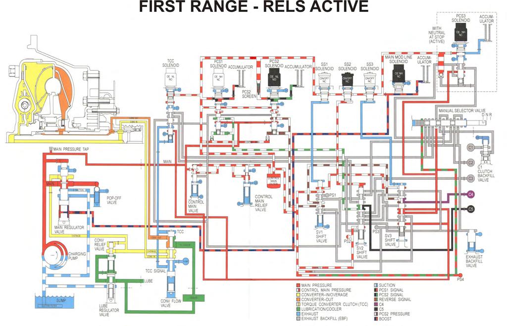
30 Main modulation line pressure control Page 13 As of the 2010 Uprate, the Main Modulation Solenoid, formerly known as Solenoid G, is now a variable controlled solenoid rather than an ON/OFF. This allows main line pressure to be constantly adjusted to load imposed on on the transmission as well as throttle position. Electrical system failures will cause the TCM to shut down the solenoid circuit which will result in maximum line pressure operation. Some diagnostic codes will allow only a stepped increment type of line pressure operation. In order for full functionality of Variable Modulated Pressure feature, Shift Energy Management (SEM) and Low Range Torque Protection (LRTP) must be fully operational. 22/23

31 Line pressure specs with sem Page 14 Line pressure specs without sem 23/23
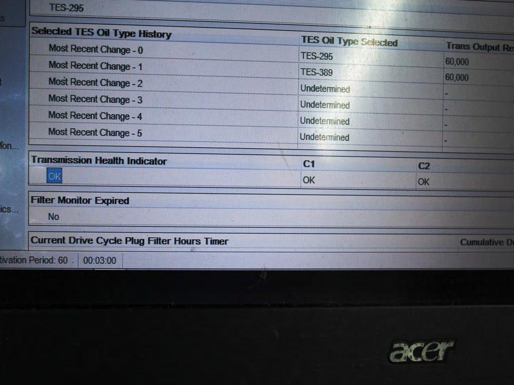
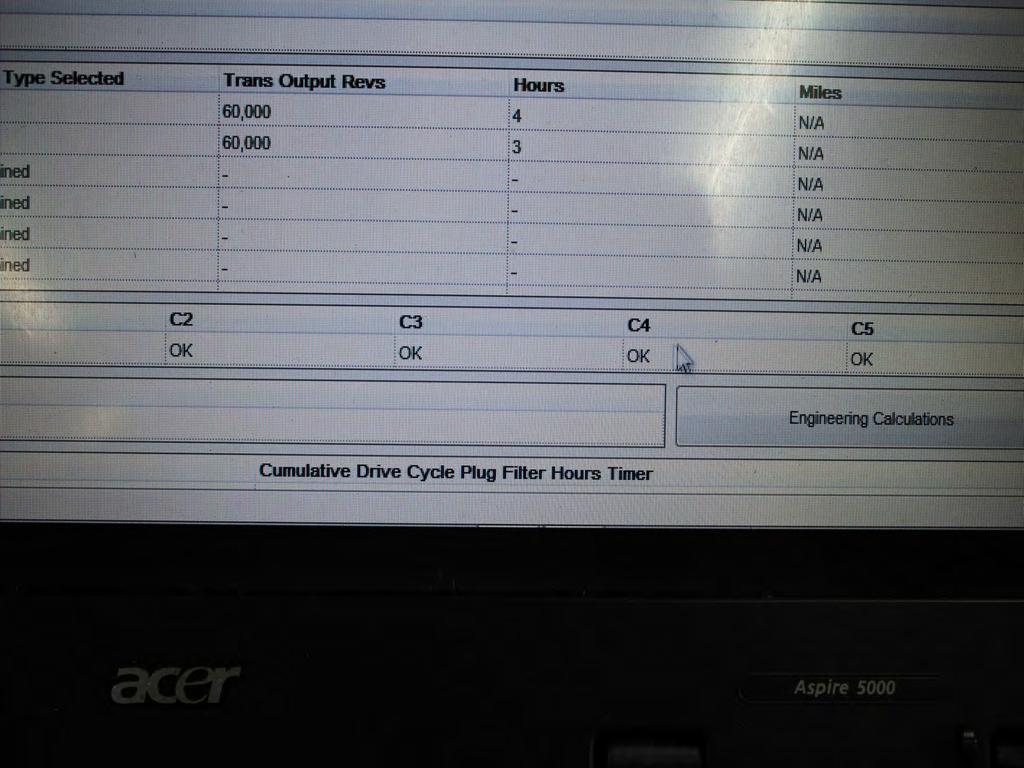
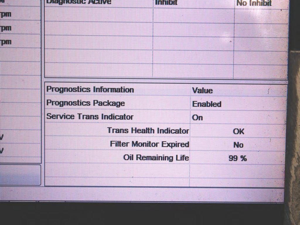
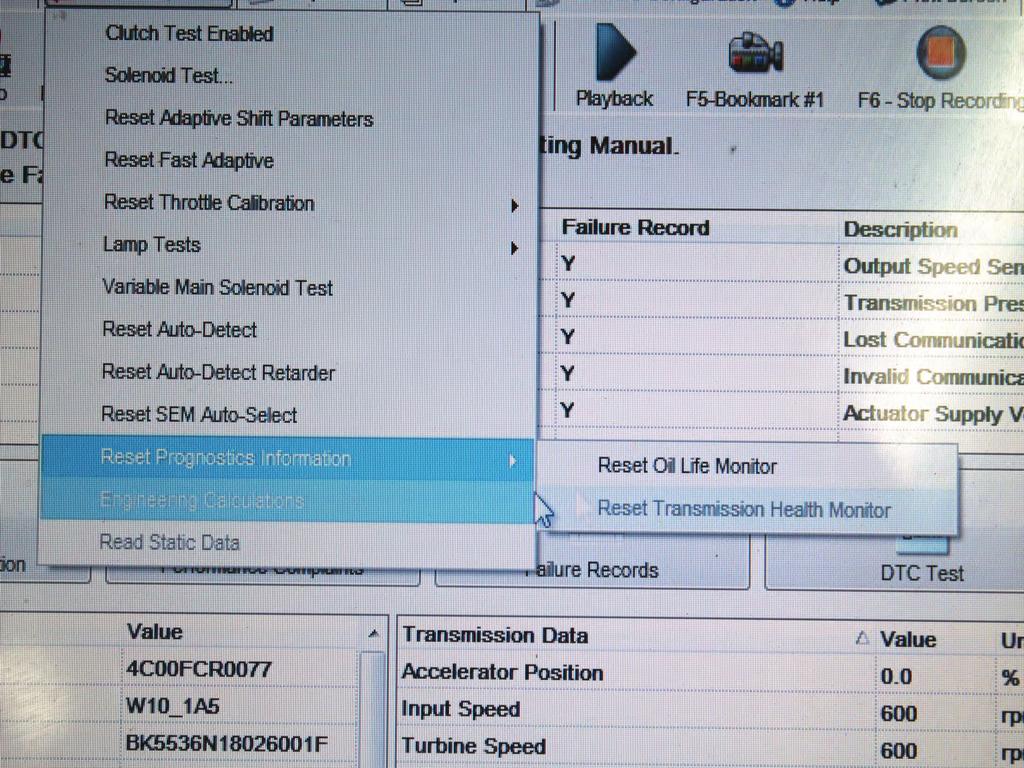
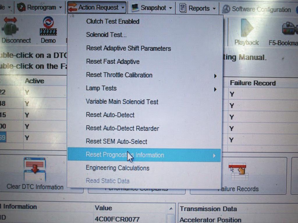
32 4 th & 5 th generation prognostics Page 15 At the start of production for the 2009 model year Allison introduced Prognostics for the GEN 4 control systems and continued its use into the present for GEN 5 control systems. Prognostics is software that monitors transmission oil life, filter life and transmission health. The software is a combination of computer strategies designed to maximize transmission fluid, filter and friction plate health. Prognostics can be enabled or disabled using the Allison DOC Service Tool. The monitoring process is performed by the TCM which utilizes the following inputs: Shifts Per Mile Transmission Revolutions Hours Of Run Time Clutch Adaptives Prognostics provides the following additional DTC capability: P0897 = Transmission Fluid Deteriorated P088B = Transmission Filter Very Deteriorated P2789 = Clutch Adaptive Learning At Limit 1/21

33 2/21/1A PPT
34 3/21 PPT
35 4/21 PPT

36 4 th & 5 th generation prognostics Page 15 Allison insists that only approved fluids and high quality filters be used for Prognostics to have maximum effect. The following is a list of approved fluids. 5/21

37 6/21 Page 15

38 4 th & 5 th generation prognostics Oil life monitor: Vehicles equipped with Prognostics are equipped with a Service Trans Lamp which will illuminate for 2 minutes after each TCM initialization when the TCM determines that the Oil Life Monitor has detected that oil life is at 2%. Oil Life can be reset to 100% using the Allison DOC Service Tool or by the following manual reset procedure: Using the manual shift selector lever, select N-R-N-R-N-D-N pausing briefly (Less Than 3 Seconds) between each selector lever movement with key ON and engine OFF. Page 15 If the reset is not performed, then the Check Trans Lamp will illuminate and DTC P0897 = Transmission Fluid Deteriorated will be set. 7/21

39 4 th & 5 th generation prognostics filter life monitor: The Service Trans Lamp will flash with each TCM initialization when the TCM determines that the oil filter has reached the end of its life. The lamp will continue to flash for 2 minutes after Drive has been selected. Page 15 The filter life can be reset to 100% using the Allison DOC Service Tool or it can be manually reset by using the manual shift selector lever, select N-R-N- R-N-D-N with key ON and engine OFF pausing briefly between each selector lever movement (Less Than 3 Seconds). Failure to perform the reset will result in the Check Trans Lamp illuminating and DTC P088B = Transmission Filter Very Deteriorated being set. 8/21

40 4 th & 5 th generation prognostics Transmission health monitor: The Service Trans Lamp will illuminate steadily with each TCM initialization when the TCM determines that the Transmission Health Monitor indicates that remaining clutch life reached approximately 10%, or if clutch clearance exceeds maximum value. The indicator will reset when the clutch clearance issue is resolved or by using the Allison DOC Service Tool. Page 15 If the Health Monitor has not been reset within 100 hours, the Check Trans Lamp will illuminate and DTC P2789 = Clutch Adaptive Learning At Limit will set. 9/21
41 10/21 PPT
42 11/21 PPT
43 12/21 PPT
44 13/21 PPT


45 Shallow pan sump FILTER Page 16 PREVIOUS FILTER CURRENT FILTER 14/21

46 Shallow pan Page /8 DRAIN PLUG 15/21


47 DEEP pan sump FILTER Page 17 PREVIOUS FILTER CURRENT FILTER 16/21

48 DEEP pan Page 17 17/21 4 7/16 DRAIN PLUG

49 HIGH PERFORMANCE DEEP pan PPT 18/21

50 TRANSMISSION fluid specifications Page 18 19/21

51 SPIN-ON TRANSMISSION FILTER Page 18 20/21

52 SPIN-ON TRANSMISSION FILTER Page 18 WATCH FOR MAGNET RESTRICTING HOLES ON SOME FILTERS 21/21
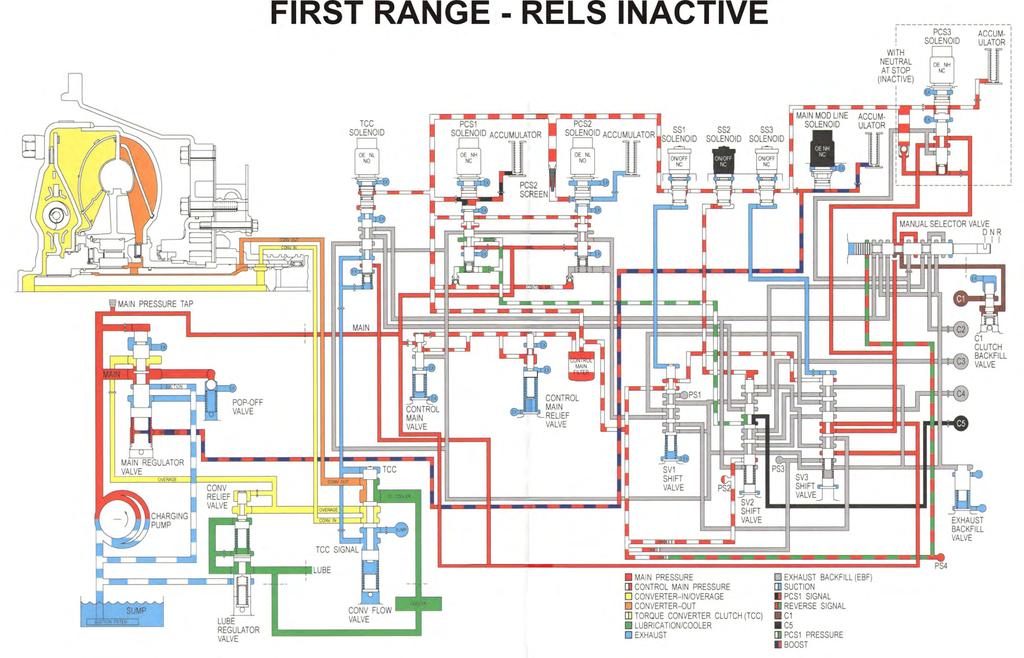
53 Reduced engine load at a stop (rels) Page 19 At the start of production for the 2013 Model Year, Allison introduced to the 1000/2000 Series Reduced Engine Load At A Stop (RELS) which can also be referred to as Neutral At A Stop which is meant to reduce engine load which results in better fuel economy. RELS will require new software as well as additional hardware and is considered optional which means not all vehicles will have this feature. When RELS is active, the TCM will command low pressure to the C1 Clutch using Pressure Control Solenoid 3 and its regulating valve. To Activate RELS, the vehicle must be in 1 st Range, at a stop, service brakes applied, throttle at zero % and the TCM must see B+ from a customer supplied Brake Pressure Switch. RELS deactivates when the service brake is released. Should RELS become in a Stuck ON or OFF condition, DTC P071A = Neutral at A Stop Input Failed ON will be set. 1/14
54 2/14 PPT
55 3/14 PPT

56 Non-rels equipped PPT 4/14

57 5/14 rels equipped Page 20

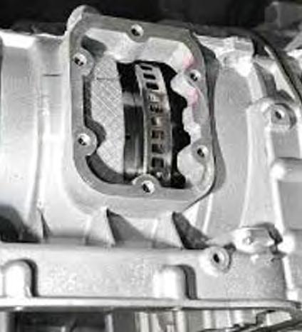
58 Page 20 RELS VALVE BODY 6/14

59 Page 20 PRESSURE CONTROL SOLENOID 3 7/14

60 Transmission case connector Page 20 PIN 12 PCS3 LOW PIN 13 PCS3 HIGH WITHOUT RELS 22 PINS WITH RELS 24 PINS 8/14

61 Page 21 NEW LOCATION OF VB DOWEL PIN HOLE 9/14

62 Page 21 DOWEL PIN MOVED ON MAIN VALVE BODY 10/14

63 Page 22 ADDED DOWEL PIN ALIGNMENT HOLES FLUID PASSAGE HOLES 11/14

64 DOWEL PIN HOLE MOVED EXTRA MATERIAL FOR ID rels SPACER PLATE SLOT REMOVED Page 23 SLOT ADDED 12/14
65 Non-rels SPACER PLATE Page 23 MATERIAL REMOVED FOR ID HAS SLOT NO SLOT 13/14

66 Page 24 RELS SPACER PLATE RELS VALVE BODY PCS3 ACCUMULATOR PCS3 REGULATOR VALVE TRAIN PCS3 SOLENOID 14/14

67 PPT Diagnostic Trouble codes 1/3
68 ALLISON 1000/2000 DIAGNOSTIC TROUBLE CODES Pgs DTCs listed in the handout service 1 st through 5 th generation control systems. Vehicles that are NON-OBD-II compliant have a Check Trans Lamp. Vehicles that are OBD-II compliant have a Malfunction Indicator Lamp as well as a Check Trans Lamp. Many fault codes will place the transmission in Limp Mode, this is sometimes perceived as a No Move condition. To determine which you have disconnect the transmission case connector and see if the transmission has 3 rd and Reverse ranges, if it does its in Limp Mode. If the key is cycled ON and OFF when the Check Trans Lamp is illuminated, and an active code is stored, The transmission may remain in NEUTRAL with no response from the shift selector lever. This can cause the Shift Inhibit Lamp to illuminate. Some malfunctions will cause the PRNDL Indicator Lamps to flash. Some DTCs can be logged without turning ON the Check Trans Lamp if the TCM determines the problem will not cause immediate damage to the transmission. 2/3

69 OPERATING RANGES DURING ELECTRICAL INTERRUPTION PPT 3/3

70 Allison 1000/2000 gear ratios Page 31 1/9

71 2/9/1M/2A PPT

72 Planetary gearsets Page 32 P1 P2 P3 3/9


73 sun gears Page 32 P1 P2 P3 4/9


74 ring gears Page 32 P1 P2 P3 5/9

75 Geartrain component tooth counts Page 33 6/9

76 Page 33 CLOSE RATIO WIDE RATIO 7/9

77 Geartrain component tooth pitch Page 33 80º PITCH 72º PITCH 8/9 Geartrain Component Teeth Prior To 2006 Have A 72 Degree Pitch. Geartrain Component Teeth After To 2006 Have A 80 Degree Pitch.

78 P1 Planetary PPT Check P1 Planet Teeth To P2 Ring Gear For Wear 9/9

79 Harsh, Slipping or Flared Shifts, Solenoid Performance Codes Set PPT TURBINE SPEED SENSOR 1/12
80 2/12 PPT

81 3/12 Page 35

82 4/12/1M PPT

83 PPT RECORD SNAPSHOT 5/12/1M
84 6/12 PPT
85 7/12 PPT

86 Clutch test PPT 8/12

87 solenoid test PPT 9/12
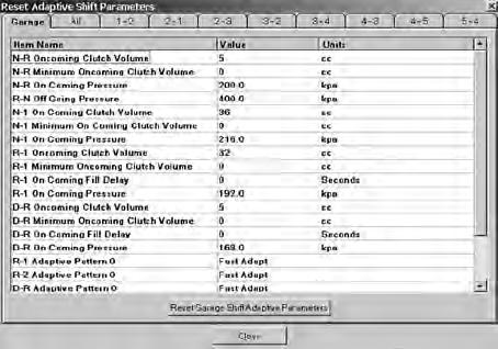
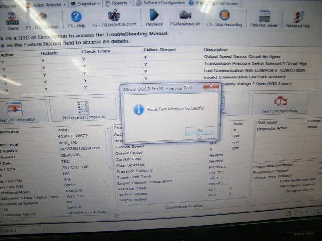
88 Shift adapts PPT Select Fast Shift Adapts. This will allow the TCM to make large changes in initial shift conditions. It will adjust for major system tolerances such as solenoid to solenoid, main pressure and clutch to clutch variations. Once the initial reset has been performed, the TCM will enter Slow Adaptive Mode, this will fine tune shift logic as the vehicle is driven. It is normal to see the TCM switch between Fast and Slow Modes. Scan Tool Display: VALUE = The amount of units provided for a particular shift. UNITS = The type of measurement for a given value. ONCOMING CLUTCH VOLUME = The total amount of fluid used to apply an oncoming clutch. ONCOMING PRESSURE = The hydraulic pressure being applied to the shifts oncoming clutch. OFF GOING PRESSURE = The hydraulic pressure remaining in the shifts off going clutch apply circuit. ONCOMING FILL DELAY = Indicates the lag time between when the clutch is commanded ON by the TCM vs. actual clutch apply time. 10/12
89 11/12 PPT
90 12/12 PPT

91 3 rd range PPT C1 & C3 clutches are applied. C1 clutch application locks the turbine shaft and the main shaft together causing them to rotate at the same speed and in the same direction. The P1 sun gear rotates with the clutch inside the P1 carrier. The P1 sun gear transmits the torque produced at the clutch to the P1 carrier. Applying stationary clutch C3 prevents the P1 ring gear from rotating. With the P1 ring gear held and the P1 sun gear providing first stage torque input, the P1 carrier Is the first stage output member in 3 rd range. 1/8
92 5th range PPT C2 & C3 clutches are applied. C2 clutch application locks the turbine shaft & the P2 carrier together, causing them to rotate as one at the same speed and in the same direction. Input to the P1 planetary is through the P1 sun gear. The P1 sun gear is part of the rotating clutch. When the C3 clutch is engaged, the P1 ring gear is held. The P1 sun gear rotating inside the P1 Carrier which provides output to the P2 ring gear. 2/8

93 Loss of 3 rd & 5 th ranges Page 37 ROTATING CLUTCH MODULE 3/8

94 4/8 Page 37

95 5/8 Page 37

96 6/8 Page 37

97 7/8 Page 37

98 Page 37 CHECK LUGS IN DRUM FOR WEAR 8/8

99 Page 39 C1 PISTON/C2 PISTON HOUSING SNAP RING IS INSTALLED IN THE NEXT GROOVE UP C1 O-RING SEAL IS INSTALLED IN THE LOWEST GROOVE 1/1


100 1 st design level Page 41 LONG CHANNEL NOT RECOMMENDED FOR USE NO METERING GROOVE 37 TOOTH OUTER GEAR 31 TOOTH INNER GEAR 1/4/1M


101 2nd design level Page 41 METERING GROOVE 2/4 37 TOOTH OUTER GEAR 31 TOOTH INNER GEAR


102 3rd design level Page 41 SHORTER CHANNEL NO METERING GROOVE 3/4 26 TOOTH OUTER GEAR 22 TOOTH INNER GEAR
103 4/4 PPT

104 DTC P0960 = SOLENOID G CIRCUIT OPEN Page 43 SOLENOID G HARNESS UNSECURED 1/2

105 DTC P0960 = SOLENOID G CIRCUIT OPEN Page 43 SOLENOID G HARNESS SECURED WITH WIRE TIE 2/2

106 Nsbu switches PPT 3RD DESIGN 2ND DESIGN 1 ST DESIGN 1/8

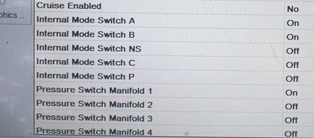
107 2/8 INTERNAL MODE switch Page 45

108 3/8 INTERNAL MODE switch Page 45

109 Page 45 Pin A = Park/Neutral Signal Pin B = Range P Pin C = Range A Pin D = Range B Pin E = Range C Pin F = Ground 4/8

110 5/8 Ims case connector terminal id Page 46

111 6/8 Ims range logic Page 47
112 7/8 PPT

113 8/8 Ims switch state Page 47
114 1/4 PPT

115 2/4 Page 49
116 3/4 PPT
117 4/4 PPT

118 1/3 Page 51

119 2/3 Page 51
120 3/3 PPT
121 3000/4000 SERIES

122 Rotating module hub Page 53 HUB CRACKS HERE 1/5

123 2/5 Page 53

124 3/5 Page 53

125 4/5 Front cover Page 53

126 Page 53 MODIFIED FRONT COVER 5/5
127 Aisin 6 (a465) SERIES
128 Aisin 6 (a465) transmission Page Isuzu N Series trucks and Chevrolet/GMC W Series Trucks equipped with the A465 6 Speed Transmission and 5.2L or 3.0L Diesel Engine and a diesel particulate filter may have a complaint of the Check Trans Lamp illuminated with one or more of the following DTCs: Model Years: P0745 = Exhaust Brake Cut Request Circuit Malfunction P0742 = TCC Stuck ON P0751 = Shift solenoid 1 Stuck OFF P0756 = Shift Solenoid 1 Stuck ON P0761 = Shift Solenoid 3 Stuck ON P0766 Shift Solenoid 3 Stuck OFF P0796 = Pressure Control Solenoid 3 Performance Model Years (5.2L Diesel Engine): P0503 = Vehicle Speed Sensor Circuit Intermittent Fault P0707 = Transmission Range Switch Circuit Low P0708 = Transmission Range Switch Circuit High P0742 = TCC Stuck ON P0746 = Pressure Control Solenoid 1 Performance P0751 = Shift solenoid 1 Stuck OFF 1/2
129 Aisin 6 (a465) transmission Page Model Years (3.0L Diesel Engine): P0756 = Shift Solenoid 1 Stuck ON P0761 = Shift Solenoid 3 Stuck ON P0766 Shift Solenoid 3 Stuck OFF P0776 = Pressure Control Solenoid 2 Performance P0796 = Pressure Control Solenoid 3 Performance P084B = Transmission Fluid Pressure Switch 8 Performance CAUSE: TCM Software Conflicts. Correction: Reprogram TCM with latest software calibrations. 2/2

130 1/6 10 pin internal harness Page 56 & 57

131 10 pin internal harness Page 56 & 57 2/6

132 12 pin internal harness Page 56 & 57 3/6

133 12 pin internal harness Page 56 & 57 4/6

134 Page 56 & 57 ISUZU PN /6

135 Page 56 & 57 ISUZU PN /6

136 RC TRUCK PARTS /1/1M

137 4L80E SERIES

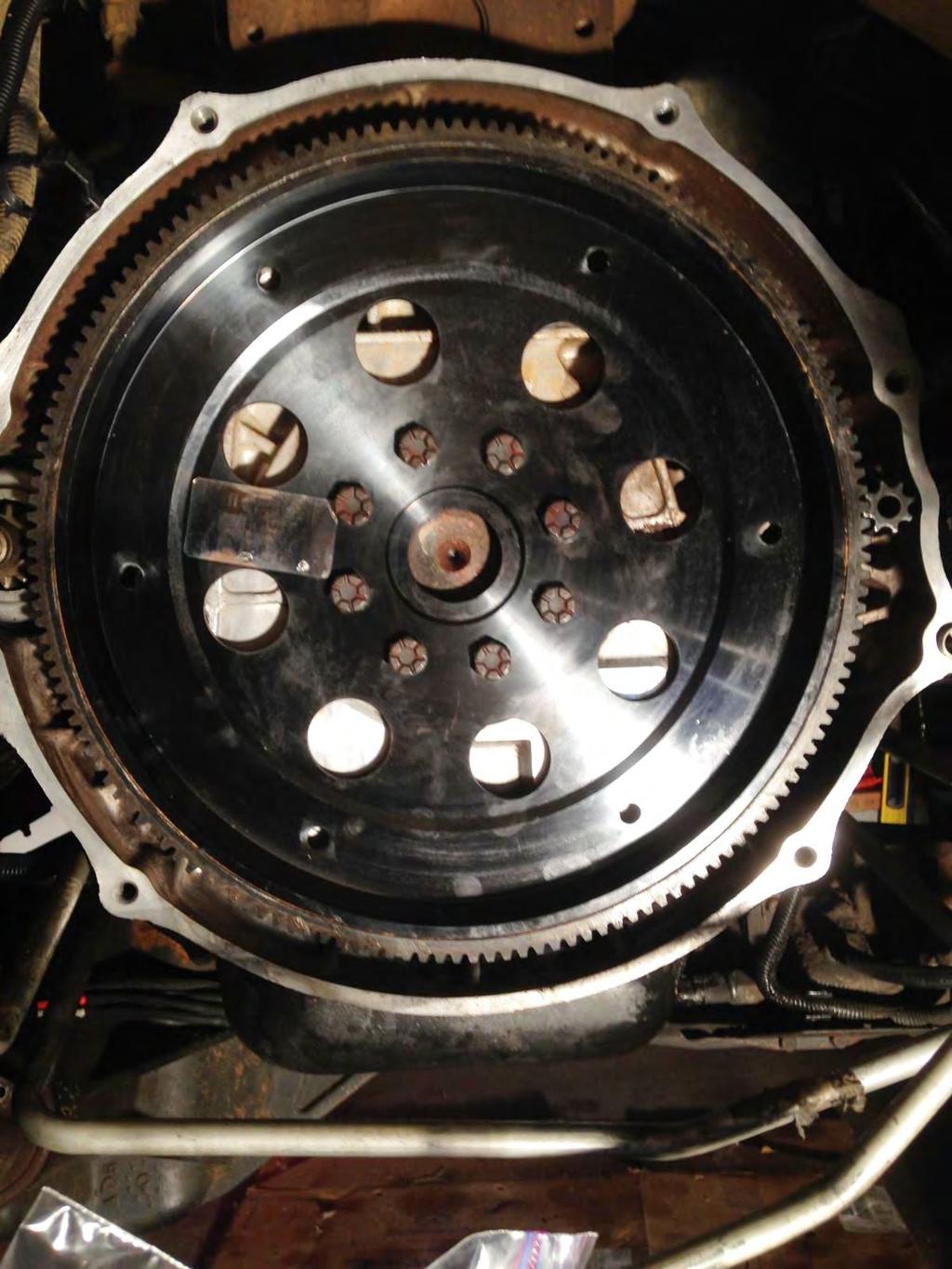
138 n series truck with 6.0L gas engine & 4l85E transmission Page 59 MISSING BOLTS FLYWHEEL/CONVERTER COVER 1/3

139 2/3 6.0L gas engine PPT
140 Page 59 FEELER GAUGE STRAIGHT EDGE /3
141

142 Hino trucks with in cab meritor wabco abs ecu Page 61 ACTIVE ABS CODES CAUSE NO LOCKUP WITH A SEVERE TRANSMISSION OVERTEMP CONDITION 1/7

143 2/7 Page 60 & 61

144 3/7 Page 60 & 61

145 Page 62 9 PIN ROUND CONNECTOR FOR HINO DX SCAN TOOL ABS DIAGNOSIS SWITCH 4/7
146 Abs code retrieval & clearing using abs warning lamp & Diagnostic switch Page 60 CODE RETRIEVAL: Turn starter key ON. Press & hold for one second the Diagnosis Switch, then release it. Count 2 digit flashes from the ABS Warning Lamp to determine code. After the 1 st digit flashes there will be a 1.5 second pause until the 2 nd digit starts flashing. After the 2 nd digit flashes there will be a 4 second pause between the next code or to repeat the previous code. Use the code definition chart in Figure 4. CODE CLEARING: Turn starter key ON. Press & hold the Diagnosis Switch for at least 3 seconds, then release it. The ABS Warning Lamp should now flash 8 times. IMPORTANT NOTE: The vehicle must reach a speed of at least 4 MPH for the ABS Warning Lamp to go out. 5/7

147 CONNECT DLC 3 TERMINALS 4 & 13 Page 62 TERMINAL 4 TERMINAL 13 6/7
148 Abs code retrieval & clearing using abs warning lamp & Dlc3 connector Page 61 CODE RETRIEVAL: Connect a jumper wire to DLC3 connector terminals 4 (CG) and 13 (TC). Turn starter key ON. Read the flash code pattern from the ABS Warning Lamp using chart in Figure 5. There will be a 1.5 second pause between the 1 st & 2 nd digit followed by a 4 second pause until the next code starts flashing or repeats the previous code. Remove Jumper wire from the DLC3. CODE CLEARING: Connect a jumper wire to DLC3 connector terminals 4 (CG) and 13 (TC). Turn starter key ON & operate the brake pedal at least 8 times within 5 seconds. The ABS Warning Lamp should flash steadily and then go out. Remove jumper wire from the DLC3. 7/7
149
SECTION 5 DIAGNOSTIC TROUBLE CODES (DTC)
") 5 1. DTC MEMORY SECTION 5 Diagnostic Trouble Codes (DTCs) are logged in a list in TCM memory. The DTCs contained in the list have information recorded as shown in Table 5 1 (DTC example). The TCM is capable
5 1. DTC MEMORY SECTION 5 Diagnostic Trouble Codes (DTCs) are logged in a list in TCM memory. The DTCs contained in the list have information recorded as shown in Table 5 1 (DTC example). The TCM is capable
LX AUTOMATIC TRANSMISSION NAG1 - SERVICE INFORMATION TABLE OF CONTENTS
 LX AUTOMATIC TRANSMISSION NAG1 - SERVICE INFORMATION 21-495 AUTOMATIC TRANSMISSION NAG1 - SERVICE INFORMATION TABLE OF CONTENTS page AUTOMATIC TRANSMISSION NAG1 - SERVICE INFORMATION DESCRIPTION...496
ALLISON IDENTIFICATION TAG
 ALLISON IDENTIFICATION TAG 1000 2000 2000MH 2400 Heavy duty automatic transmission with parking pawl. maximum GVW = 19850 lb. Heavy duty automatic transmission without parking pawl. maximum GVW = 30000
SHIFT SELECTOR OPERATION AND CODE MANUAL
 SHIFT SELECTOR OPERATION AND MANUAL How to use the shift selector to read oil level and diagnostic codes on 3000/4000 Series Allison transmissions P.O. Box 894, Speed Code 462-470-PF3 Indianapolis, Indiana
AISIN WARNER. 1. With the selector lever in Park, start the engine and warm it to operating temperature.
 AISIN WARNER 249 Manual Code Retrieval Preliminary Test: 1. With the selector lever in Park, start the engine and warm it to operating temperature. 2. Turn the ignition switch to the Off position, then
G - TESTS W/CODES - 2.2L
 G - TESTS W/CODES - 2.2L 1994 Toyota Celica 1994 ENGINE PERFORMANCE Toyota 2.2L Self-Diagnostics Celica INTRODUCTION If no faults were found while performing F - BASIC TESTING, proceed with self-diagnostics.
6T30/6T40/6T45 - AUTOMATIC TRANSMISSION
 2010 GMC Truck Terrain AWD L4-2.4L Vehicle > ALL Diagnostic Trouble Codes ( DTC ) > Testing and Inspection > P Code Charts > P0717 6T30/6T40/6T45 - AUTOMATIC TRANSMISSION DTC P0716 or P0717 Diagnostic
OPERATION FIRST GEAR POWERFLOW TJ - JEEP WRANGLER - 4.0L 6 CYL (MPI) 21 - Transmission and Transfer Case/Automatic - 42RLE/Operation
 21 - Transmission and Transfer Case/Automatic - 42RLE/Operation") 2006 - TJ - JEEP WRANGLER - 4.0L 6 CYL (MPI) 21 - Transmission and Transfer Case/Automatic - 42RLE/Operation OPERATION The 42RLE transmission ratios are: GEAR RATIO First 2.84 : 1 Second 1.57 : 1 Third
2006 - TJ - JEEP WRANGLER - 4.0L 6 CYL (MPI) 21 - Transmission and Transfer Case/Automatic - 42RLE/Operation OPERATION The 42RLE transmission ratios are: GEAR RATIO First 2.84 : 1 Second 1.57 : 1 Third
Continuously Variable Transaxle Specification. Forward/Reverse Switching Mechanism Double Pinion Type Planetary Gear
 CVT SYSTEM > GENERAL OUTLINE 1. A newly developed K41A Continuously Variable Transaxle (CVT) is used for the1kr-fe engine models. 2. The K41A CVT, including a pair of the pulleys and the belt in the shift
CRUISE CONTROL SYSTEM
 CRUISE CONTROL SYSTEM 1994 Toyota Celica 1994 ACCESSORIES & EQUIPMENT Toyota Motor Sales, U.S.A., Inc. - Cruise Control Systems Celica DESCRIPTION Cruise control system consists of Cruise Control Electronic
1999 Toyota RAV ACCESSORIES & EQUIPMENT Cruise Control Systems - RAV4
 1999 ACCESSORIES & EQUIPMENT Cruise Control Systems - RAV4 DESCRIPTION WARNING: Deactivate air bag system before performing any service operation. See AIR BAG RESTRAINT SYSTEMS article. DO NOT apply electrical
WTEC III SHIFT SELECTOR
 WTEC III SHIFT SELECTOR P.O. Box 894, Speed Code PF3 Indianapolis, Indiana 46206-0894 www.allisontransmission.com Oil level information, diagnostic codes and prognostic features for SA7297EN (2012/12)
AUTOMATIC TRANSMISSION (5AT)
") (5AT) GENERAL 1. General To improve the dynamic performance and fuel efficiency of the vehicle, a new 5-speed automatic transmission is developed. The features of this new automatic transmission are as
(5AT) GENERAL 1. General To improve the dynamic performance and fuel efficiency of the vehicle, a new 5-speed automatic transmission is developed. The features of this new automatic transmission are as
Operator s Manual and 2000 Product Families OM3063EN MT4108EN
 Operator s Manual 1000 and 2000 Product Families OM3063EN MT4108EN Operator s Manual 2003 JUNE Rev. 1 2004 JULY OM3063EN Allison Transmission On-Highway 1000 and 2000 Product Families Allison Transmission,
Continuously Variable Transaxle Specification. Forward/Reverse Switching Mechanism Double Pinion Type Planetary Gear
 CVT SYSTEM > GENERAL OUTLINE 1. A newly developed K41B Continuously Variable Transaxle (CVT) is used for the1nr-fe engine models. 2. The K41B CVT, including a pair of the pulleys and the belt in the shift
 Page 1 of 10 Main Components and Functions Torque Converter 1 Cover (Part of 7902) 2 Converter Damper Plate 3 O-Ring (Part of 7902) 4 Turbine Assembly (Part of 7902) 5 Selective Spacer 6 Thrust Washer
4L80E Updates. Transmission: Subject: Application: Issue Date: Chevrolet L80E. Updates ACTUATOR FEED LIMIT FLUID SPOOL VALVE SPRING
 Transmission: Subject: Application: Issue Date: Technical Bulletin #266 4L80E Updates Chevrolet 1995 4L80E Updates Many electrical changes have occurred in the 4L80E transmission for the 1994 model year,
Powertrain DTC Summaries EOBD
 Powertrain DTC Summaries Quick Reference Diagnostic Guide Jaguar X-TYPE 2.0 L 2002.25 Model Year Refer to page 2 for important information regarding the use of Powertrain DTC Summaries. Jaguar X-TYPE 2.0
Diagnostic Trouble Code (DTC) Charts
 Charts") SECTION 307-01: Automatic Transaxle/Transmission 5R55S 2009 Mustang Workshop Manual DIAGNOSIS AND TESTING Procedure revision date: 06/30/2009 Diagnostic Trouble Code (DTC) Charts DTC Chart **May also be
SECTION 307-01: Automatic Transaxle/Transmission 5R55S 2009 Mustang Workshop Manual DIAGNOSIS AND TESTING Procedure revision date: 06/30/2009 Diagnostic Trouble Code (DTC) Charts DTC Chart **May also be
Allison LCT1000. Presented by: Mike Souza ATRA Senior Research Technician Allison LCT1000 Webinar 2014 ATRA. All Rights Reserved.
 Allison LCT1000 Presented by: Mike Souza ATRA Senior Research Technician Allison LCT1000 Webinar 2014 ATRA. All Rights Reserved. Generation Changes 2000 to 2005 Gen I Allison LCT1000 are 5 speeds. In
MECHANIC S TIPS 1000/2000 PRODUCT FAMILIES. ALLISON 4th GENERATION CONTROLS 2010 UPRATE MT4007EN
 MECHANIC S TIPS 1000/2000 PRODUCT FAMILIES ALLISON 4th GENERATION CONTROLS 2010 UPRATE MT4007EN Mechanic s Tips 2010 NOVEMBER MT4007EN Allison Transmission 2010 Uprate Allison 4 th Generation Controls
Shift Solenoid "B" Performance (Shift Solenoid Valve S2)
") 86 A750E AUTOMIC TRANSMISSION AUTOMIC TRANSMISSION SYSTEM DTC P0756 Shift Solenoid "B" Performance (Shift Solenoid Valve S2) DESCRIPTION The ECM uses signals from the output shaft speed sensor and input
86 A750E AUTOMIC TRANSMISSION AUTOMIC TRANSMISSION SYSTEM DTC P0756 Shift Solenoid "B" Performance (Shift Solenoid Valve S2) DESCRIPTION The ECM uses signals from the output shaft speed sensor and input
Introduction to the GM 6L80. Presented By: Steve Garrett
 Introduction to the GM 6L80 Presented By: Steve Garrett 6L80 (RPO MYC) Introduction The first of ten 6 speed automatics was introduced in the 2006 model year. The 6L80 (RPO MYC) is currently available
Table of Contents INTRO
 GENERAL ALL Wheel Drive Systems General System Overview...2 Transfer Coupling...3 Diagnostics, Tire Wear, Codes...4 Rolling Circumference Test...5 Getrag 760 T-Case Introduction and Service Information...6
PRE CHECK DI 456. w/ Tachometer. w/o Tachometer. Hand held Tester AUTOMATIC TRANSMISSION (A340E, A340F) 2003 TOYOTA TACOMA (RM1002U) D10837 D00729
 2003 TOYOTA TACOMA (RM1002U) D10837 D00729") DI456 w/ Tachometer w/o Tachometer D10837 PRECHECK DI8Z403 1. DIAGNOSIS SYSTEM (a) Description When troubleshooting OBD II vehicles, the only difference from the usual troubleshooting procedure is that
DI456 w/ Tachometer w/o Tachometer D10837 PRECHECK DI8Z403 1. DIAGNOSIS SYSTEM (a) Description When troubleshooting OBD II vehicles, the only difference from the usual troubleshooting procedure is that
Mercedes Presented by Dr William (Bill) Henney PhD F.I.M.I
 Henney PhD F.I.M.I") Mercedes 722.9 Presented by Dr William (Bill) Henney PhD F.I.M.I Features Electronically Controlled Automatic Gearbox 7 Forward and 2 Reverse Gears Transmission Control Module is : Integrated into the
Mercedes 722.9 Presented by Dr William (Bill) Henney PhD F.I.M.I Features Electronically Controlled Automatic Gearbox 7 Forward and 2 Reverse Gears Transmission Control Module is : Integrated into the
A750E AUTOMATIC TRANSMISSION: AUTOMATIC TRANSMISSION SYSTEM (for 1GR-FE)... Model Year: 2007 Model: 4Runner Doc ID: RM000000XP101WX
... Model Year: 2007 Model: 4Runner Doc ID: RM000000XP101WX") Last Modified: 4-26-2007 Service Category: Drivetrain 1.6 C Section: Automatic Transmission/Transaxle Model Year: 2007 Model: 4Runner Doc ID: RM000000XP101WX Title: A750E AUTOMATIC TRANSMISSION: AUTOMATIC
Last Modified: 4-26-2007 Service Category: Drivetrain 1.6 C Section: Automatic Transmission/Transaxle Model Year: 2007 Model: 4Runner Doc ID: RM000000XP101WX Title: A750E AUTOMATIC TRANSMISSION: AUTOMATIC
DTC P0743 sets when the TCM detects an open circuit, a short to power, or a short to ground in the TCC PWM solenoid circuit for 1.5 seconds.
 Page 1 of 5 2005 GMC Truck GMC K Sierra - 4WD Sierra, Silverado VIN C/K Service Manual Document ID: 1492351 DTC P0743 Circuit Description The torque converter clutch (TCC) solenoid is a pulse width modulated
Module 5: Cooling Fundamentals
 Terms and Definitions Major Mechanical Parts of a Four Speed Auto Transmission Parts of a Planetary Gear System Planetary Gear System Operation Speed, Torque, and Directional Function Fluid Pump and Pressure
AUTOMATIC TRANSMISSIONS. General Motors Corp. Hydra-Matic 4L60-E Overhaul
 1997-98 AUTOMATIC TRANSMISSIONS General Motors Corp. Hydra-Matic 4L60-E Overhaul APPLICATION TRANSMISSION APPLICATIONS Application Corvette Transaxle 4L60-E IDENTIFICATION The 4L60-E transmission can be
The parking brake is an electrically actuated system that operates drum brakes integrated into the rear brake discs. The
 Page 1 of 15 Published: Oct 22, 2004 Parking Brake COMPONENT LOCATIONS Item Part Number Description 1 Clutch pedal position sensor (manual transmission models only) 2 Parking brake indicators (all except
Shift Solenoid "B" Performance (Shift Solenoid Valve S2)
") 88 A750F AUTOMIC TRANSMISSION AUTOMIC TRANSMISSION SYSTEM DTC P0756 Shift Solenoid "B" Performance (Shift Solenoid Valve S2) DESCRIPTION The ECM uses signals from the output shaft speed sensor and input
88 A750F AUTOMIC TRANSMISSION AUTOMIC TRANSMISSION SYSTEM DTC P0756 Shift Solenoid "B" Performance (Shift Solenoid Valve S2) DESCRIPTION The ECM uses signals from the output shaft speed sensor and input
L (LS1) F-car (Camaro, Firebird), Y-car (Corvette) 4L60-E TRANSMISSION DIAGNOSTIC PARAMETERS. 99c57G_FY_aT.DOC
 F-car (Camaro, Firebird), Y-car (Corvette) 4L60-E TRANSMISSION DIAGNOSTIC PARAMETERS. 99c57G_FY_aT.DOC") SECONDRY S ND Vehicle Speed Sensor - Low input Vehicle Speed Sensor - Intermittent P0502 0 RPM to 6000 RPM low vehicle speed when the vehicle has a large engine speed in a drive gear range. P0503 0 RPM
SECONDRY S ND Vehicle Speed Sensor - Low input Vehicle Speed Sensor - Intermittent P0502 0 RPM to 6000 RPM low vehicle speed when the vehicle has a large engine speed in a drive gear range. P0503 0 RPM
DIAGNOSIS AND TESTING
 307-01-1 Automatic Transaxle/Transmission 307-01-1 DIAGNOSIS AND TESTING Pinpoint Tests OSC Equipped Vehicle Special Tool(s) Transmission Fluid Pressure Gauge 307-004 (T57L-77820-A) Special Tool(s) MLP-TR
2002 Ford Explorer AUTOMATIC TRANSMISSIONS' '5R55W/S Diagnosis 2002 AUTOMATIC TRANSMISSIONS. 5R55W/S Diagnosis
 2002 AUTOMATIC TRANSMISSIONS 5R55W/S Diagnosis APPLICATION WARNING: Vehicles are equipped with Supplemental Inflatable Restraint (SIR) system. When servicing vehicle, use care to avoid accidental air bag
Shift Solenoid "A" Performance (Shift Solenoid Valve S1)
") 78 DTC P0751 Shift Solenoid "A" Performance (Shift Solenoid Valve S1) DESCRIPTION The ECM uses signals from the output shaft speed sensor and input speed sensor to detect the actual gear position (1st,
78 DTC P0751 Shift Solenoid "A" Performance (Shift Solenoid Valve S1) DESCRIPTION The ECM uses signals from the output shaft speed sensor and input speed sensor to detect the actual gear position (1st,
DESCRIPTION. Chrysler NCV3 Service Info Section 08 > Electronic Modules > MODULE, Transmission Control Information
 DESCRIPTION The transmission control module (TCM) receives, processes and sends various digital and analog signals related to the automatic transmission. In addition, it processes information received
DTC Summaries. W5A-580 Transmission Control System 1998 MY
 DTC Summaries W5A-580 Transmission Control System 1998 MY OBD II MONITORING CONDITIONS: When testing for OBD II DTC reoccurrence, it can be determined if the Service Drive Cycle was of sufficient length
SECTION Electronic Engine Controls
 303-14-i Electronic Engine Controls 303-14-i SECTION 303-14 Electronic Engine Controls CONTENTS PAGE DIAGNOSIS AND TESTING Electronic Engine Controls... 303-14-2 DTC Charts... 303-14-2 303-14-2 Electronic
DSI M78 6-SPEED A/T / / / / / DSI M78 6-SPEED A/T GENERAL INFORMATION OVERVIEW AND OPERATION PROCESS
 DSI M78 6SPEED A/T 311001/365001/366001/368001/372101/921001 DSI M78 6SPEED A/T GENERAL INFORMATION 1. DSI M78 6SPEED AUTOMATIC TRANSMISSION GENERAL... 2. STRUCTURE CHARACTERISTICS AND SPECIFICATIONS...
ENGINE AND EMISSION CONTROL
 17-1 GROUP 17 ENGINE AND EMISSION CONTROL CONTENTS ENGINE CONTROL.......... 17-3 GENERAL DESCRIPTION...... 17-3 ENGINE CONTROL SYSTEM DIAGNOSIS.................. 17-3 INTRODUCTION TO ENGINE CONTROL SYSTEM
1. GENERAL INFORMATION
 368001 023 1. GENERAL INFORMATION DSI M78 Automatic Transmission is based on the transmission in the vehicle with D20DT engine for EURO III or EURO IV. Differences: changed some components (torque converter
DIAGNOSIS AND TESTING
 307-01-1 Automatic Transaxle/Transmission 307-01-1 DIAGNOSIS AND TESTING Diagnostic Trouble Code Charts Diagnostic Trouble Code Chart P0102, MAF MAF concerns MAF system High/low EPC REFER to the P0103,
ANTI-LOCK BRAKING SYSTEM (ABS)
") 35B-1 GROUP 35B ANTI-LOCK BRAKING SYSTEM (ABS) CONTENTS GENERAL DESCRIPTION......... 35B-2 ANTI-SKID BRAKING SYSTEM (ABS) DIAGNOSIS.................... 35B-3 INTRODUCTION TO ANTI-LOCK BRAKE SYSTEM DIAGNOSIS................
35B-1 GROUP 35B ANTI-LOCK BRAKING SYSTEM (ABS) CONTENTS GENERAL DESCRIPTION......... 35B-2 ANTI-SKID BRAKING SYSTEM (ABS) DIAGNOSIS.................... 35B-3 INTRODUCTION TO ANTI-LOCK BRAKE SYSTEM DIAGNOSIS................
Vehicle makes models and variants known or believed to be using this vehicle system, required diagnostic lead and degree of known compatibility.
 BOSCH AUTO BOX GS8.87.1 - System Overview Manufactured by Bosch, this ECU appears to compliment the Motronic M5.2.1 Engine management system. Not being Flash Programmable, there are two near identical
U140E AND U241E AUTOMATIC TRANSAXLE
 CH-125 U140E AND U241E AUTOMATIC TRANSAXLE DESCRIPTI The 02 Camry line-up uses the following types of automatic transaxles: 2AZ-FE U241E 1MZ-FE U140E These automatic transaxles are compact and high-capacity
DTC Summaries. 5 HP 24 Transmission Control System 1997 MY
 DTC Summaries 5 HP 24 Transmission Control System 1997 MY OBD II MONITORING CONDITIONS: When testing for OBD II DTC reoccurrence, it can be determined if the Service Drive Cycle was of sufficient length
GROUP 17 CONTENTS WARNINGS REGARDING SERVICING OF SUPPLEMENTAL RESTRAINT SYSTEM (SRS) EQUIPPED VEHICLES
 EQUIPPED VEHICLES") 17-1 GROUP 17 CONTENTS ENGINE CONTROL 17-4 GENERAL DESCRIPTION 17-4 ENGINE CONTROL SYSTEM DIAGNOSIS 17-4 INTRODUCTION TO ENGINE CONTROL SYSTEM DIAGNOSIS 17-4 ENGINE CONTROL SYSTEM DIAGNOSTIC TROUBLESHOOTING
17-1 GROUP 17 CONTENTS ENGINE CONTROL 17-4 GENERAL DESCRIPTION 17-4 ENGINE CONTROL SYSTEM DIAGNOSIS 17-4 INTRODUCTION TO ENGINE CONTROL SYSTEM DIAGNOSIS 17-4 ENGINE CONTROL SYSTEM DIAGNOSTIC TROUBLESHOOTING
 Page 1 of 13 437: Transmission control module (TCM), TF-80SC AWD XC90, 2007, D5244T4, TF-80SC AWD, L.H.D, YV1CM714671338226, 338226 7/7/2016 PRINT 437: Transmission control module (TCM), TF-80SC AWD Adaptation
DI 244 DIAGNOSTICS AUTOMATIC TRANSMISSION DIB30 01 PRE CHECK
 DI244 DIAGNOSTICS PRECHECK DIB3001 1. DIAGNOSIS SYSTEM (a) Description When troubleshooting OBD II vehicles, the only difference from the usual troubleshooting procedure is that you connect to the vehicle
L (L36) F-car 4L60-E TRANSMISSION DIAGNOSTIC PARAMETERS. 97c38K_F at.doc
 F-car 4L60-E TRANSMISSION DIAGNOSTIC PARAMETERS. 97c38K_F at.doc") Vehicle Speed Sensor - Low input Vehicle Speed Sensor - Intermittent Trans Fluid Temp Sensor Circuit - Range / Performance P0502 P0503 0 RPM to 6000 RPM low vehicle speed when the vehicle has a large engine
Vehicle Speed Sensor - Low input Vehicle Speed Sensor - Intermittent Trans Fluid Temp Sensor Circuit - Range / Performance P0502 P0503 0 RPM to 6000 RPM low vehicle speed when the vehicle has a large engine
AUTOMATIC TRANSMISSION (DIAGNOSTICS)
") AUTOMATIC TRANSMISSION (DIAGNOSTICS) Basic Diagnostic Procedure 1. Basic Diagnostic Procedure A: PROCEDURE Is the unit that is thought to Go to step 2. influence the AT problem working properly? 1 CHECK
AUTOMATIC TRANSMISSION (DIAGNOSTICS) Basic Diagnostic Procedure 1. Basic Diagnostic Procedure A: PROCEDURE Is the unit that is thought to Go to step 2. influence the AT problem working properly? 1 CHECK
P0733 DTC P0733 A/T 3RD GEAR FUNCTION
 2003 Nissan-Datsun Altima L4-2.5L (QR25DE) Vehicle > ALL Diagnostic Trouble Codes ( DTC ) > Testing and Inspection > P Code Charts P0733 DTC P0733 A/T 3RD GEAR FUNCTION Description - This is an OBD-II
ELECTRONIC CONTROL SYSTEM. 1. General CH-16 CHASSIS - U340E AUTOMATIC TRANSAXLE
 CH-16 ELECTRONIC CONTROL SYSTEM 1. General The electronic control system of the U340E automatic transaxle consists of the controls listed below. System Clutch Pressure Control (See page CH-20) Line Pressure
ZF4HP16. Technical Bulletin # Signal Combination L1 L2 L3 L4 P R N D
 Transmission: Subject: Application: Issue Date: Technical Bulletin # 1308 ZF4HP16 Electronical Components Description 2005 Suzuki Forenza L4-2.0L February, 2010 ZF4HP16 Electronical Components Description
2011 Dodge or Ram Truck RAM 3500 Truck 4WD L6-6.7L DSL Turbo
 1 of 10 10/14/2013 9:23 AM 2011 Dodge or Ram Truck RAM 3500 Truck 4WD L6-6.7L DSL Turbo Vehicle» A L L Diagnostic Trouble Codes ( DTC )» Testing and Inspection» P Code Charts» P0732 P0732-GEAR RATIO ERROR
Geo Prizm ( LSi) Toyota Celica 1.8L (1994)
 Toyota Celica 1.8L (1994)") Page 1 of 140 ARTICLE BEGINNING APPLICATION TRANSMISSION APPLICATIONS Application Geo Prizm (1993-94 LSi) Toyota Celica 1.6L (1993) Celica 1.8L (1994) Celica 2.2L (1993) Corolla 1.8L MR2 Paseo Transaxle
Page 1 of 140 ARTICLE BEGINNING APPLICATION TRANSMISSION APPLICATIONS Application Geo Prizm (1993-94 LSi) Toyota Celica 1.6L (1993) Celica 1.8L (1994) Celica 2.2L (1993) Corolla 1.8L MR2 Paseo Transaxle
Diagnostic Trouble Codes (continued) GM Specific Codes
 GM Specific Codes") 85 GM Specific Codes P11XX Fuel and Air Metering P1106 MAP Sensor Circuit Intermittent High Voltage P1107 MAP Sensor Circuit Intermittent Low Voltage P1108 BARO to MAP Signal Comparison Too High P1111
85 GM Specific Codes P11XX Fuel and Air Metering P1106 MAP Sensor Circuit Intermittent High Voltage P1107 MAP Sensor Circuit Intermittent Low Voltage P1108 BARO to MAP Signal Comparison Too High P1111
FORD 6R80 UPDATES Presented by: David Chalker ATRA Technical Advisor 6R80
 FORD UPDATES Presented by: David Chalker ATRA Technical Advisor Welcome To Today s Presentation Sponsored By: Any Questions Or Comments Please Send Emails To webinars@atra.com Any Questions That You
ENRESO.WORLD. Traction Control System. Created by Istas René - enreso.world. Graduated in Autmotomotiv Technolgogys
 ENRESO.WORLD Traction Control System Created by Istas René - enreso.world Graduated in Autmotomotiv Technolgogys Traction Control (TCS) is an option that is often found on vehicles equipped with antilock
A750F AUTOMATIC TRANSMISSION: AUTOMATIC TRANSMISSION SYSTEM (for 1GR-FE)... Model Year: 2007 Model: 4Runner Doc ID: RM000000W80023X
... Model Year: 2007 Model: 4Runner Doc ID: RM000000W80023X") Last Modified: 4-26-2007 Service Category: Drivetrain 1.6 C Section: Automatic Transmission/Transaxle Model Year: 2007 Model: 4Runner Doc ID: RM000000W80023X Title: A750F AUTOMATIC TRANSMISSION: AUTOMATIC
Last Modified: 4-26-2007 Service Category: Drivetrain 1.6 C Section: Automatic Transmission/Transaxle Model Year: 2007 Model: 4Runner Doc ID: RM000000W80023X Title: A750F AUTOMATIC TRANSMISSION: AUTOMATIC
Alternative Fuel Engine Control Unit
 1999 Chevrolet/Geo Cavalier (CNG) Alternative Fuel Engine Control Unit Table 1: AF ECU Function Parameters The (AF ECU) controls alternative fuel engine operation. The control unit monitors various engine
Technical Service Information Bulletin
 Technical Service Information Bulletin August 4, 2003 Title: Models: 02 03 ES 300 & 04 05 ES 330 REVISION NOTICE: April 1, 2005: 2004 2005 model year ES 330 vehicles have been added to Applicable Vehicles.
Cruise Control Diagnosis
 1999 Pontiac Firebird Cruise Control Diagnosis Circuit Description The Cruise Control system is a speed control system that maintains a desired vehicle speed under normal driving conditions. The cruise
Ford CFT 30 Introduction. Presented by: Bill Brayton ATRA Senior Research Technician
 Ford CFT 30 Introduction Presented by: Bill Brayton ATRA Senior Research Technician Connections Handout Webinars@ATRA.com Questions Survey Welcome To Today s Presentation Sponsored By: Thank you to our
CHASSIS AUTOMATIC TRANSAXLE. Destination New Model Previous Model Change (from previous model)
") CHASSIS AUTOMATIC TRANSAXLE CH-37 U341E AUTOMATIC TRANSAXLE 1. General The compact and high-capacity 4-speed U341E automatic transaxle [Super ECT (Electronic Controlled Transaxle)] is used. The following
CHASSIS AUTOMATIC TRANSAXLE CH-37 U341E AUTOMATIC TRANSAXLE 1. General The compact and high-capacity 4-speed U341E automatic transaxle [Super ECT (Electronic Controlled Transaxle)] is used. The following
Technical Bulletin Listing 2009
 Technical Bulletin Listing 2009 Transmission Bulletin # # Pages Subject January U140E/U241E 1225 1 Harsh 2-3 Shift After Overhaul GM MP T-Case 1226 10 Introduction 6T70/75 1227 1 Transfer Bolt Eliminated
 TRACTION CONTROL SYSTEM 1996 Toyota Supra 1995-96 BRAKES Traction Control Supra DESCRIPTION Toyota Traction Control (TRAC) system controls engine torque and braking of the driving wheels. TRAC system is
Service Bulletin Buses
 Prevost Saint-Nicolas, Quebec, Canada Service Bulletin Buses Date Group No. Release Page 6.2010 364 00 1(12) Vehicle Electronic Control Unit (VECU) MID 144, Diagnostic Trouble Code (DTC), Guide Vehicle
Technical Bulletin # 1251
 Transmission: Subject: Application: Issue Date: CD4E TCC Slip Code Diagnosis Ford, Mercury and Mazda May 2009 CD4E TCC Slip Code Diagnosis Once the check engine light illuminates, the transmission will
ANTI-LOCK BRAKING SYSTEM (ABS)
") 35B-1 GROUP 35B ANTI-LOCK BRAKING SYSTEM (ABS) CONTENTS GENERAL DESCRIPTION......... 35B-2................ 35B-4 INTRODUCTION TO ANTI-LOCK BRAKING SYSTEM DIAGNOSIS................ 35B-4 ABS DIAGNOSTIC
35B-1 GROUP 35B ANTI-LOCK BRAKING SYSTEM (ABS) CONTENTS GENERAL DESCRIPTION......... 35B-2................ 35B-4 INTRODUCTION TO ANTI-LOCK BRAKING SYSTEM DIAGNOSIS................ 35B-4 ABS DIAGNOSTIC
DTC P Shift Solenoid Circuit Electrical
 1998 Pontiac Grand Prix DTC P0753 1-2 Shift Solenoid Circuit Electrical Circuit Description The 1-2 Shift Solenoid Valve Assembly (1-2 SS Valve Assy.) controls the transmission fluid pressure on the 1-2
TRACTION CONTROL SYSTEM (TCL)
") 35C-1 GROUP 35C TRACTION CONTROL SYSTEM (TCL) CONTENTS GENERAL DESCRIPTION 35C-2 DIAGNOSIS 35C-4 INTRODUCTION TO TRACTION CONTROL SYSTEM DIAGNOSIS 35C-4 TCL DIAGNOSTIC TROUBLESHOOTING STRATEGY 35C-4 DIAGNOSTIC
35C-1 GROUP 35C TRACTION CONTROL SYSTEM (TCL) CONTENTS GENERAL DESCRIPTION 35C-2 DIAGNOSIS 35C-4 INTRODUCTION TO TRACTION CONTROL SYSTEM DIAGNOSIS 35C-4 TCL DIAGNOSTIC TROUBLESHOOTING STRATEGY 35C-4 DIAGNOSTIC
TRANSMISSION - NGC. Symptom: P0706-CHECK SHIFTER SIGNAL. When Monitored and Set Condition:
 Symptom: P0706-CHECK SHIFTER SIGNAL When Monitored and Set Condition: P0706-CHECK SHIFTER SIGNAL When Monitored: Continuously with the ignition on. Set Condition: After 3 occurrences in one ignition cycle
DTC P0502 Vehicle Speed Sensor (VSS) Circuit Low Input (3.1L VIN M)
 Circuit Low Input (3.1L VIN M)") Page 1 of 5 1996 Pontiac Grand Am Achieva, Grand Am, Skylark (VIN N) Service Manual Document ID: 49145 DTC P0502 Vehicle Speed Sensor (VSS) Circuit Low Input (3.1L VIN M) Circuit Description The Vehicle
Page 1 of 5 1996 Pontiac Grand Am Achieva, Grand Am, Skylark (VIN N) Service Manual Document ID: 49145 DTC P0502 Vehicle Speed Sensor (VSS) Circuit Low Input (3.1L VIN M) Circuit Description The Vehicle
Condition. Correction. Document ID:
 Document ID: 1351952 #02-07-30-025B: Harsh Shifting, Delayed Upshifts with Possible CHECK TRANS Lamp Illuminated, Possible DTC 21 Set (Perform TPS Relearn Procedure) - (Jun 27, 2003) Subject: Harsh Shifting,
L SUPERCHARGED (L67) C-car, G-car, H-car and W-car 4T65-E TRANSMISSION DIAGNOSTIC PARAMETERS. 97c381_CGHWT.doc
 C-car, G-car, H-car and W-car 4T65-E TRANSMISSION DIAGNOSTIC PARAMETERS. 97c381_CGHWT.doc") Vehicle Speed Sensor - Low input Vehicle Speed Sensor - Intermittent Trans Fluid Temp Sensor Circuit - Range / Performance Input/Turbine Speed Sensor Range /Performance P0502 P0503 P0711 P0716 low vehicle
Vehicle Speed Sensor - Low input Vehicle Speed Sensor - Intermittent Trans Fluid Temp Sensor Circuit - Range / Performance Input/Turbine Speed Sensor Range /Performance P0502 P0503 P0711 P0716 low vehicle
12.Electrohydraulic Control System
 W1860BE.book Page 67 Tuesday, January 28, 2003 11:01 PM 12.Electrohydraulic Control System A: DESCRIPTION The electrohydraulic system for the transmission and transfer consists of various sensors and switches,
2006 F-150/Mark LT Workshop Manual
 Page 1 of 14 SECTION 307-01: Automatic Transaxle/Transmission 4R70E/4R75E DIAGNOSIS AND TESTING Procedure revision date: 09/26/2008 Pinpoint Tests OSC Equipped Vehicle Printable View (485 KB) Special Tool(s)
Allison Lockup Controller
 19 February 2018 1031311/1031312/1031313 Allison Transmission Lockup and Pressure Module (I-00413) 1 Allison Lockup Controller Transmission Lockup and Pressure Controller 1031311 1031312 1031313 2001-2010
THE witech SOFTWARE LEVEL MUST BE AT RELEASE **15.04** OR HIGHER TO PERFORM THIS PROCEDURE.
 2014 RAM 3500 HD 6.7L Eng Big Horn FLASH: 6.7L DIAGNOSTIC AND SYSTEM IMPROVEMENTS TECHNICAL SERVICE BULLETIN Reference Number(s): 18-045-15, Date of Issue: May 20, 2015 CHRYSLER: 2014 Ram 2500 Pick Up
2003 CVT when used with 2.2L L61 engine in the Saturn ION TRANSMISSION DIAGNOSTIC PARAMETERS
 TCM Memory ROM P0601 The code is designed to verify ROM checksum at key up. TCM Not Programmed P0602 The code is designed to verify that the TCM has been programmed. TCM Long Term Memory Reset P0603 This
GROUP 35A 35A-1 CONTENTS GENERAL DESCRIPTION... 35A-3 BASIC BRAKE SYSTEM DIAGNOSIS 35A-6 HYDRAULIC BRAKE BOOSTER (HBB) DIAGNOSIS...
 DIAGNOSIS...") 35A-1 GROUP 35A CONTENTS GENERAL DESCRIPTION......... 35A-3 DIAGNOSIS 35A-6 INTRODUCTION..................... 35A-6 DIAGNOSTIC TROUBLESHOOTING STRATEGY......................... 35A-6 SYMPTOM CHART...................
35A-1 GROUP 35A CONTENTS GENERAL DESCRIPTION......... 35A-3 DIAGNOSIS 35A-6 INTRODUCTION..................... 35A-6 DIAGNOSTIC TROUBLESHOOTING STRATEGY......................... 35A-6 SYMPTOM CHART...................
Transmission Description
 Page 1 of 23 Published: Feb 1, 2007 Transmission Description COMPONENT LOCATION Item Part Number Description 1 Transmission selector lever assembly 2 Cable bracket 3 Automatic transmission 4 Transmission
ATRA WEBINAR Chrysler CVT-2 Introduction
 ATRA WEBINAR Chrysler CVT-2 Introduction Sponsored By: Presented by: Steve Garrett ATRA Today s Presentation Sponsored By: Lwiggins@ATRA.com Connections Handout Questions Survey Thanks A special thanks
Life cycle value. When you factor in all life cycle costs. No power interrupts. Torque converter. Proven reliability and durability.
 OCTOBER 2009 Allison Transmission is Optimized. Our commitment to understand and satisfy your needs drives us to constantly analyze, refine and improve our products and their features. Nothing else delivers
AUTOMATIC TRANSMISSION (DIAGNOSTICS) AT
 AT") AUTOMATIC TRANSMISSION (DIAGNOSTICS) AT Page 1. Basic Diagnostic Procedure...2 2. Check List for Interview...4 3. General Description...5 4. Electrical Components Location...7 5. Transmission Control Module
AUTOMATIC TRANSMISSION (DIAGNOSTICS) AT Page 1. Basic Diagnostic Procedure...2 2. Check List for Interview...4 3. General Description...5 4. Electrical Components Location...7 5. Transmission Control Module
FOR HELP WITH USING witech FOR ECU FLASH REPROGRAMMING, CLICK ON THE APPLICATION S HELP TAB.
 NUMBER: 18-091-16 GROUP: Vehicle Performance DATE: July 26, 2016 This bulletin is supplied as technical information only and is not an authorization for repair. No part of this publication may be reproduced,
BASIC BRAKE SYSTEM GROUP 35A 35A-1 CONTENTS GENERAL DESCRIPTION... 35A-3 BASIC BRAKE SYSTEM DIAGNOSIS 35A-6
 35A-1 GROUP 35A BASIC BRAKE SYSTEM CONTENTS GENERAL DESCRIPTION......... 35A-3 DIAGNOSIS 35A-6 INTRODUCTION..................... 35A-6 DIAGNOSTIC TROUBLESHOOTING STRATEGY......................... 35A-6
Powertrain DTC Summaries OBD II
 Powertrain DTC Summaries Quick Reference Diagnostic Guide Jaguar X-TYPE 2.5L and 3.0L 2002 Model Year Revised January, 2002: P0706, P0731, P0732, P0733, P0734, P0735, P0740, P1780 POSSIBLE CAUSES Revised
ALLISON 1000 SIGNATURE SERIES
 ALLISON 1000 SIGNATURE SERIES 2001-2010 DURAMAX GPZ 1 FLUID CAPACITY INSTALLATION In our RevMax performance transmission we require you to use DEXRON 3 fluid and are shipped empty due to the regulations
Pinpoint Tests OSC Equipped Vehicle
 SECTION 307-01: Automatic Transaxle/Transmission 5R55S 2009 Mustang Workshop Manual DIAGNOSIS AND TESTING Procedure revision date: 11/19/2008 Pinpoint Tests OSC Equipped Vehicle Special Tool(s) 73 III
DTC P0300-P0308. Diagnostic Instructions. DTC Descriptors. Circuit/System Description. Conditions for Running the DTC
 Page 1 of 5 2009 GMC Truck Sierra - 2WD Sierra, Silverado (VIN C/K) Service Manual Engine Engine Mechanical - 4.8L, 5.3L, 6.0L, 6.2L, or 7.0L Description and Operation DTC P0300-P0308 Diagnostic Instructions
Technical Bulletin Listing 2009
 Technical Bulletin Listing 2009 May, 2009 Transmission Bulletin # # Pages Subject January U140E/U241E 1225 1 Harsh 2-3 Shift After Overhaul GM MP T-Case 1226 10 Introduction 6T70/75 1227 1 Transfer Bolt
TCU 1) CONNECTOR INFORMATION 2) CONNECTOR IDENTIFICATION SYMBOL & PIN NUMBER POSITION CIRCUIT ACTYON
 CONNECTOR INFORMATION 2) CONNECTOR IDENTIFICATION SYMBOL & PIN NUMBER POSITION CIRCUIT ACTYON") 311001 017 311001 TCU 1) CONNECTOR INFORMATION 2) CONNECTOR IDENTIFICATION SYMBOL & PIN NUMBER POSITION 018 311001 (3) DESCRIPTION A. ION (BTRA) M74 4WD AUTOMATIC TRANSMISSION The ION (BTR) Four Speed
311001 017 311001 TCU 1) CONNECTOR INFORMATION 2) CONNECTOR IDENTIFICATION SYMBOL & PIN NUMBER POSITION 018 311001 (3) DESCRIPTION A. ION (BTRA) M74 4WD AUTOMATIC TRANSMISSION The ION (BTR) Four Speed
Powertrain DTC Summaries EOBD
 Powertrain DTC Summaries Quick Reference Diagnostic Guide Jaguar S-TYPE V6, V8 N/A and V8 SC 2002.5 Model Year Refer to pages 2 9 for important information regarding the use of Powertrain DTC Summaries.
HOW TO PROCEED WITH TROUBLESHOOTING
 2005 BRAKES Anti-Lock Brake System With Electronic Brake Force Distribution (EBD) - Diagnostics - RAV4 HOW TO PROCEED WITH TROUBLESHOOTING Troubleshoot in accordance with the following procedures. Fig.
2001 Chevrolet Corvette ACCESSORIES & EQUIPMENT Cruise Control Systems - Corvette
 2001 ACCESSORIES & EQUIPMENT Cruise Control Systems - Corvette DESCRIPTION Cruise control is a speed control system that maintains a desired vehicle speed under normal driving conditions. Steep grades
Powertrain DTC Summaries EOBD
 Powertrain DTC Summaries Quick Reference Diagnostic Guide Jaguar X-TYPE 2.5L and 3.0L 2001.5 Model Year Revised January, 2002: P0706, P0731, P0732, P0733, P0734, P0735, P0740, P1780 POSSIBLE CAUSES Revised
FOR HELP WITH USING witech FOR ECU FLASH REPROGRAMMING, CLICK ON THE APPLICATION S HELP TAB.
 NUMBER: 18-043-17 GROUP: Vehicle Performance DATE: May 04, 2017 This bulletin is supplied as technical information only and is not an authorization for repair. No part of this publication may be reproduced,