AUTOMATIC TRANSMISSION (DC 5-SPEED) GENERAL 1. AUTOMATIC TRANSMISSION OVERVIEW
|
|
|
- Cornelius Waters
- 5 years ago
- Views:
Transcription


1 02-4 AUTOMATIC TRANSMISSION () GENERAL 1. AUTOMATIC TRANSMISSION OVERVIEW DC 5-speed Automatic Transmission Assembly T-Tronic DC 5-speed automatic transmission is an electronically controlled 5-speed transmission with a lockup clutch in the torque converter. The ratios for the gears are realized by three planetary gear sets. The 5th gear is designed with a stepup ratio of 0.83 as an overdrive. The selector lever is controlled by electronically and mechanically. The gears are shifted by the corresponding combination of three hydraulically actuated multiple-disc brakes, three hydraulically actuated multiple-disc clutches and two mechanical oneway clutches. This electronically controlled automatic transmission adjusts the operating pressure to provide proper shifting in relation to engine power. This function improves shifting quality significantly. And, the driver can select "S" (Standard) mode or "W" (Winter) mode according to the driving conditions.


 to achieve smooth starting")
 1 2 3 4 D The")
 direction.")
2 02-5 Instrument Panel TCU Assembly TCCU TCU Releasing Lock-up Solenoid Valve Standard Mode / Winter Mode When the gear selector lever cannot be moved from "P" position to other positions, manually release the lock-up function as shown in figure. "S" mode is used in normal driving. When "W" mode is selected, the vehicle starts from 2nd gear (forward and reverse) to achieve smooth starting on the slippery road. Selector Lever Downshift (Manual Mode) D The shiftable gear is down by one step as the lever is moved to left (-) direction. Upshift (Manual Mode) D The shiftable gear is up by one step as the lever is moved to right (+) direction.

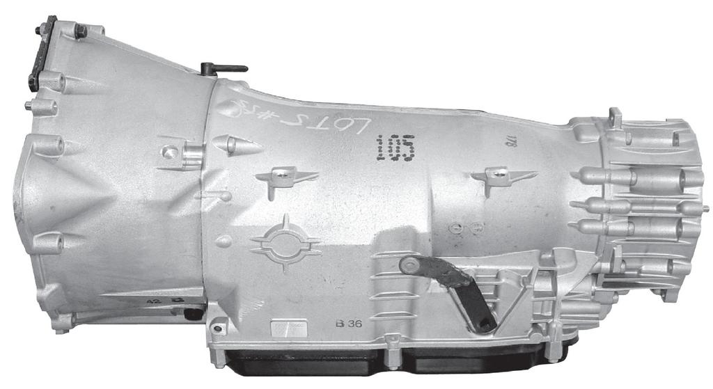
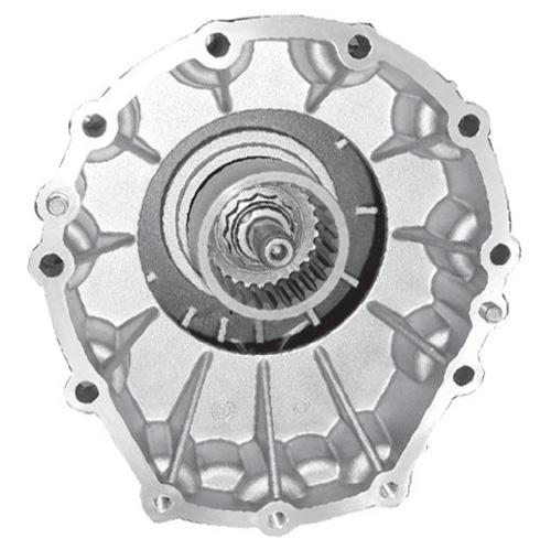
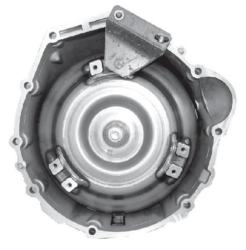
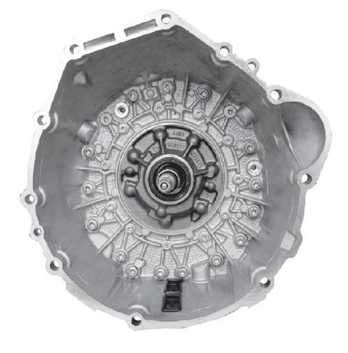
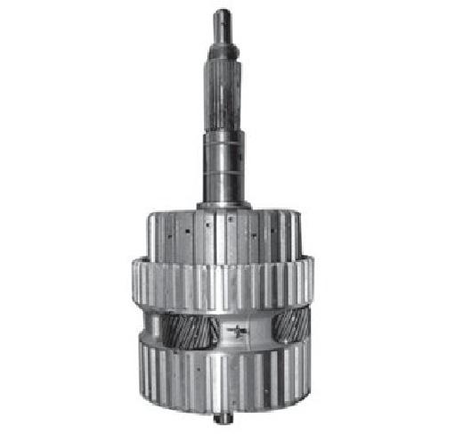
3 AUTOMATIC TRANSMISSION () APPEARANCE Left Side With Torque Converter Without Torque Converter Rear View

4 AUTOMATIC TRANSMISSION STRUCTURE This sectional drawing is based on DC 5-speed A/T 2WD model. 4WD model has also same structure. 1. Torque converter 2. Oil pump 3. Input shaft 4. Disc brake B1 5. Disc clutch C1 6. Disc clutch C2 7. Disc brake B3 8. Disc clutch C3 9. Disc brake B2 10. Output shaft 11. Parking lock gear 12. Intermediate shaft 13. Freewheel F2 14. Center planetary gear set 15. Electric control unit (valve body) 16. Freewheel F1 (Front planetary gear set) 17. Stator shaft 18. Converter lockup clutch
5 02-8 Specifications
6 02-9
7 02-10 Characteristics of Automatic Transmission - Performance Curve D20DT Standard Mode WINTER Mode (2WD) Lockup Mode (Open/Slipping) Upshift: Downshift: Lockup (slipping): Unlock (open): FAST OFF: Dynamic shift zone: FAST OFF: When abruptly releasing the accelerator pedal, the transmission remains at 4th gear other than 4 5 shift (when slowly releasing the accelerator pedal, the transmission is shifted to 5th gear). Dynamic shift zone: When operating the accelerator pedal (B), the 4 3 shift is completed by kick-down signal after completion of 4 3 shift (100% of pedal position). When promptly operating the accelerator pedal (C), the 4 3 shift is done in shaded area (93% of pedal position). 4th gear: th gear: Rev. 1st gear: Rev. 2nd gear: 1.93 Low Mode (4WD)
8 02-11 D27DT Standard Mode Lockup Mode (Open/Slipping) Upshift: Downshift: Lockup (slipping): Unlock (open): FAST OFF: Dynamic shift zone: FAST OFF: When abruptly releasing the accelerator pedal, the transmission remains at 4th gear other than 4 5 shift (when slowly releasing the accelerator pedal, the transmission is shifted to 5th gear). Dynamic shift zone: When operating the accelerator pedal (B), the 4 3 shift is completed by kick-down signal after completion of 4 3 shift (100% of pedal position). When promptly operating the accelerator pedal (C), the 4 3 shift is done in shaded area (93% of pedal position). 4th gear: th gear: Rev. 1st gear: Rev. 2nd gear: 1.93 WINTER Mode
9 02-12 General Characteristics


")
")

10 02-13 OVERVIEW AND OPERATION PROCESS 1. POWER FLOW Brake B1(disk) assembly Brake B3 (disk) assembly Brake B2 (disk) assembly C1 (Disk clutch) assembly C2 (Disk clutch) assembly C3 (Disk clutch) assembly
11 02-14 Shifting Elements 1) Selector program switch: S mode 2) Selector program switch: W mode 3) Overrun
12 ) 1st Gear (D20DT: 3.951, D27DT: 3.595) 16. Torque converter lockup clutch A. Engine speed B. Transmission, input shaft C. 1st gear ratio D. 2nd gear ratio E. 3rd gear ratio F. Locking elements H. Rear planetary gear set L. Stator M. Center planetary gear set P. Impeller T. Turbine wheel V. Front planetary gear set 1. Input shaft: Clockwise rotation 2. Front sun gear: Locked by F1 and B1, Planetary gear carrier: Rotation with reduced speed 3. Rear ring gear: clockwise rotation 4. Rear sun gear: Locked by F2 and B2, Planetary gear carrier: Clockwise rotation with reduced speed 5. Center ring gear: Clockwise rotation 6. Center sun gear: Locked by B2, Rotation with reduced speed 7. Output shaft: Clockwise rotation 3) Overrun
13 ) 2nd Gear (D20DT: 2.423, D27DT: 2.186) 16. Torque converter lockup clutch A. Engine speed B. Transmission, input shaft C. 1st gear ratio D. 2nd gear ratio E. Locking elements H. Rear planetary gear set L. Stator M. Center planetary gear set P. Impeller T. Turbine wheel V. Front planetary gear set 1. Input shaft: Clockwise rotation 2. Sun gear and planetary gear carrier: Clockwise rotation by C1 activation 3. Rear ring gear: Clockwise rotation 4. Rear sun gear: Locked by F2 and B2, Planetary gear carrier: Rotation with reduced speed 5. Center ring gear: Clockwise rotation 6. Sun gear: Locked by B2, Planetary gear carrier: Rotation with reduced speed 7. Output shaft: Clockwise rotation 3) Overrun
14 ) 3rd Gear (D20DT: 1.486, D27DT: 1.405) 16. Torque converter lockup clutch A. Engine speed B. Transmission, input shaft C. 1st gear ratio D. Locking elements H. Rear planetary gear set L. Stator M. Center planetary gear set P. Impeller T. Turbine wheel V. Front planetary gear set 1. Input shaft: Clockwise rotation 2. Front ring gear: Clockwise rotation 3. Center ring gear: Clockwise rotation by clutch 2 activation (direct connection) 4. Center sun gear: Locked by B2, Planetary gear carrier: Clockwise rotation with reduced speed 5. Output shaft: Clockwise rotation
15 ) 4th Gear (1.000) 16. Torque converter lockup clutch A. Engine speed B. Planetary gear set L. Stator M. Center planetary gear set P. Impeller T. Turbine wheel V. Front planetary gear set 1. Input shaft: Clockwise rotation 2. Front ring gear: Clockwise rotation 3. Center ring gear and rear planetary gear carrier: Clockwise rotation 4. Front sun gear and planetary gear carrier: Clockwise rotation (direct connection) 5. Rear ring gear: Clockwise rotation 6. Rear sun gear: Rotation by ring gear and planetary gear carrier (direct connection) 7. Center sun gear: Clockwise rotation by C3 activation 8. Planetary gear carrier: Clockwise rotation by center sun gear and ring gear (direct connection) 9. Output shaft: Clockwise rotation
16 ) 5th Gear (D20DT: 0.833, D27DT: 0.831) 16. Torque converter lockup clutch A. Engine speed B. Transmission, input shaft C. 1st gear ratio D. 2nd gear ratio E. 3rd gear ratio F. Locking elements H. Rear planetary gear set L. Stator M. Center planetary gear set P. Impeller T. Turbine wheel V. Front planetary gear set 1. Input shaft: Clockwise rotation 2. Front sun gear: Locked by B1, Planetary gear carrier: Rotation with reduced speed 3. Rear planetary gear ring gear: Clockwise rotation with reduced speed 4. Center ring gear and rear planetary gear carrier: Clockwise rotation by clutch C2 activation 5. Rear sun gear: Clockwise rotation because rear planetary gear carrier rotates faster than rear ring gear(increased speed) 6. Center sun gear: Clockwise rotation with increased speed by clutch C3 activation 7. Center planetary gear carrier: Clockwise rotation (increased speed) 8. Output shaft: Clockwise rotation (increased speed) 3) Overrun
17 ) Reverse 1st Gear (D20DT: 3.147, D27DT: 3.167) - Standard (S) Mode 16. Torque converter lockup clutch A. Engine speed B. Transmission, input shaft C. 1st gear ratio D. 2nd gear ratio E. Locking elements F. Locking elements H. Rear planetary gear set L. Stator M. Center planetary gear set P. Impeller T. Turbine wheel V. Front planetary gear set 1. Input shaft: Clockwise rotation 2. Front ring gear: Clockwise rotation 3. Front sun gear: Locked by one-way clutch F1 4. Front planetary gear carrier: Clockwise rotation (reduced speed) 5. Rear planetary gear ring gear: Clockwise rotation 6. Rear planetary gear carrier: Locked by B3 7. Rear sun gear and center sun gear: Counterclockwise rotation (increased speed) 8. Center ring gear: Locked by B3 9. Center planetary gear carrier: Counterclockwise rotation (reduced speed) 10. Output shaft: Counterclockwise rotation 3) Overrun
18 ) Reverse 2nd Gear (D20DT: 1.93, D27DT: 1.926) - Winter (W) Mode Mode 16. Torque converter lockup clutch A. Engine speed B. Transmission, input shaft C. 1st gear ratio D. 2nd gear ratio E. Locking elements H. Rear planetary gear set L. Stator M. Center planetary gear set P. Impeller T. Turbine wheel V. Front planetary gear set 1. Input shaft: Clockwise rotation 2. Front ring gear: Clockwise rotation 3. Front planetary gear carrier: Clockwise rotation by clutch C1 activation (direct connection) 4. Rear ring gear: Clockwise rotation 5. Rear planetary gear carrier and center ring gear: Locked by brake B3 6. Rear sun gear and center sun gear: Counterclockwise rotation (increased speed) 7. Center planetary gear carrier: Counterclockwise rotation (reduced speed) 8. Output shaft: Counterclockwise rotation
DC-5 SPEED AUTOMATIC TRANSMISSION
 01-3 DC-5 SPEED AUTOMATIC TRANSMISSION GENERAL 1. SPECIFICATIONS 01-4 01-5 OVERVIEW AND OPERATION PROCESS 1. OVERVIEW 2WD 4WD DC 5-Speed Automatic Transmission DCAG 5-speed automatic transmission is an
DC 5-SPEED AUTOMATIC TRANSMISSION
 03 1. OVERVIEW 2WD 4WD DCAG 5speed automatic transmission is an electronically controlled 5speed transmission with a lockup clutch in the torque converter. The ratios for the gears are realized by three
Automatic Transmission Basics
 Section 1 Automatic Transmission Basics Lesson Objectives 1. Describe the function of the torque converter. 2. Identify the three major components of the torque converter that contribute to the multiplication
 Page 1 of 10 Main Components and Functions Torque Converter 1 Cover (Part of 7902) 2 Converter Damper Plate 3 O-Ring (Part of 7902) 4 Turbine Assembly (Part of 7902) 5 Selective Spacer 6 Thrust Washer
Mechanical System Tests
 AT196 Mechanical System Tests STALL TEST The object of this test is to check the overall performance of the transmission and engine by measuring the stall speeds in the D and R positions. NOTICE: Perform
1. GENERAL INFORMATION
 368001 023 1. GENERAL INFORMATION DSI M78 Automatic Transmission is based on the transmission in the vehicle with D20DT engine for EURO III or EURO IV. Differences: changed some components (torque converter
CHASSIS AUTOMATIC TRANSAXLE. Destination New Model Previous Model Change (from previous model)
") CHASSIS AUTOMATIC TRANSAXLE CH-37 U341E AUTOMATIC TRANSAXLE 1. General The compact and high-capacity 4-speed U341E automatic transaxle [Super ECT (Electronic Controlled Transaxle)] is used. The following
CHASSIS AUTOMATIC TRANSAXLE CH-37 U341E AUTOMATIC TRANSAXLE 1. General The compact and high-capacity 4-speed U341E automatic transaxle [Super ECT (Electronic Controlled Transaxle)] is used. The following
SPECIFICATIONS kg (including oil) ATF DEXRON II or III. Major element Housing Part-time Bolt 11EA, M8 x 1.25
 ATF DEXRON II or III. Major element Housing Part-time Bolt 11EA, M8 x 1.25") 3240-01 05-3 1. SPECIFICATIONS Description Specifications Total length 343 mm Weight 32.4 kg (including oil) Oil capacity 1.4 L Oil type ATF DEXRON II or III Location Transfer case Major element Housing
3240-01 05-3 1. SPECIFICATIONS Description Specifications Total length 343 mm Weight 32.4 kg (including oil) Oil capacity 1.4 L Oil type ATF DEXRON II or III Location Transfer case Major element Housing
Module 5: Cooling Fundamentals
 Terms and Definitions Major Mechanical Parts of a Four Speed Auto Transmission Parts of a Planetary Gear System Planetary Gear System Operation Speed, Torque, and Directional Function Fluid Pump and Pressure
U140E AND U241E AUTOMATIC TRANSAXLE
 CH-125 U140E AND U241E AUTOMATIC TRANSAXLE DESCRIPTI The 02 Camry line-up uses the following types of automatic transaxles: 2AZ-FE U241E 1MZ-FE U140E These automatic transaxles are compact and high-capacity
U340E AND U441E AUTOMATIC TRANSAXLES
 ASSIS U340E AND U441E AUTOMATIC TRANSAXLES -41 U340E AND U441E AUTOMATIC TRANSAXLES DESCRIPTION The new model uses 2 types (U340E, U441E) of automatic transaxle. A U340E automatic transaxle is provided
LX AUTOMATIC TRANSMISSION NAG1 - SERVICE INFORMATION TABLE OF CONTENTS
 LX AUTOMATIC TRANSMISSION NAG1 - SERVICE INFORMATION 21-495 AUTOMATIC TRANSMISSION NAG1 - SERVICE INFORMATION TABLE OF CONTENTS page AUTOMATIC TRANSMISSION NAG1 - SERVICE INFORMATION DESCRIPTION...496
ELECTRONIC CONTROL SYSTEM. 1. General CH-16 CHASSIS - U340E AUTOMATIC TRANSAXLE
 CH-16 ELECTRONIC CONTROL SYSTEM 1. General The electronic control system of the U340E automatic transaxle consists of the controls listed below. System Clutch Pressure Control (See page CH-20) Line Pressure
AUTOMATIC TRANSMISSION (5AT)
") (5AT) GENERAL 1. General To improve the dynamic performance and fuel efficiency of the vehicle, a new 5-speed automatic transmission is developed. The features of this new automatic transmission are as
(5AT) GENERAL 1. General To improve the dynamic performance and fuel efficiency of the vehicle, a new 5-speed automatic transmission is developed. The features of this new automatic transmission are as
GA6HP26Z Automatic Transmission Objectives of the Module...1 Purpose of the System...2 Technical Data...5
 Table of Contents Subject Page Objectives of the Module.....................................1 Purpose of the System.......................................2 Technical Data.............................................5
Transmission Description
 Page 1 of 23 Published: Feb 1, 2007 Transmission Description COMPONENT LOCATION Item Part Number Description 1 Transmission selector lever assembly 2 Cable bracket 3 Automatic transmission 4 Transmission
Advanced Auto Tech Worksheet Auto Trans & Transaxle Chapter 40 Pages Points Due Date
 Advanced Auto Tech Worksheet Name Auto Trans & Transaxle Chapter 40 Pages 1173 1215 107 Points Due Date 1. Automatic transmissions are operated by hydraulics as well as electronics to select according
2007 Dodge Nitro R/T
 1 - TURBINE 2 - IMPELLER 2007 Dodge Nitro R/T CONVERTER-TORQUE DESCRIPTION TORQUE CONVERTER Fig. 267: Cutaway View Of Torque Converter Fig. 268: Impeller 2007 Dodge Nitro R/T 3 - STATOR 4 - INPUT SHAFT
PROBLEM SYMPTOMS TABLE
 DI476 PROBLEM SYMPTOMS TABLE HINT: If a normal code is displayed during the DTC check but the trouble still occurs, check the circuits for each symptom in the order given in the charts on the following
PROBLEM SYMPTOMS TABLE
 Last Modified: 4262007 Service Category: Drivetrain 1.6 T Section: Automatic Transmission/Transaxle Model Year: 2007 Model: 4Runner Doc ID: RM000000W7304AX Title: A750E AUTOMATIC TRANSMISSION: AUTOMATIC
PROBLEM SYMPTOMS TABLE
 A750F AUTOMATIC TRANSMISSION: AUTOMATIC TRANSMISSION SYSTEM (for 1GRFE)... Last Modified: 4262007 Service Category: Drivetrain 1.6 T Section: Automatic Transmission/Transaxle Model Year: 2007 Model: 4Runner
TGS LEVER 1. INTRODUCTION. 1) Components
 Components") 0-3 1. INTRODUCTION The TGS lever prevents inappropriate or unexpected shifting of gears to increase safety. It also helps the driver safely select a needed gear. The solenoid of the TGS lever has the
0-3 1. INTRODUCTION The TGS lever prevents inappropriate or unexpected shifting of gears to increase safety. It also helps the driver safely select a needed gear. The solenoid of the TGS lever has the
CHASSIS. Transmission Type 1st nd rd th Gear Ratio
 CH-2 CHASSIS AA80E AUTOMATIC TRANSMISSION DESCRIPTION An AA80E automatic transmission is used. This automatic transmission is a compact, lightweight and high-capacity 8-speed sport direct shift gearbox.
Service Training Edition Speed Automatic Gearbox 09A/09B. Trainer Information (GB)
") 7.02 Edition 09.2000 5-Speed Automatic Gearbox 09A/09B Trainer Information (GB) Contents Section Page General Information 2 Input and output signals 7 Control System Details 9 ATF Pressure Control 16 Lock-up
7.02 Edition 09.2000 5-Speed Automatic Gearbox 09A/09B Trainer Information (GB) Contents Section Page General Information 2 Input and output signals 7 Control System Details 9 ATF Pressure Control 16 Lock-up
VALVE BODY. Shift Pressure Control Solenoid Valve. 1. Leaf spring 2. Contact spring 3. Conductor track 4. O-ring 5. O-ring 6.
 72 3650 VALVE BODY Shift Pressure Control Solenoid Valve 8 9 7 7 A B C D 10 7 E F 1. Leaf spring 2. Contact spring 3. Conductor track 4. O-ring 5. O-ring 6. Shift plate 7. Leaf spring and socket bolt 8.
6-speed automatic transmission E60, E53. VS-22 je Baugruppe/Group: (040) 09/2003. Introduction
 09/2003. Introduction") VS-22 je Baugruppe/Group: 24 24 01 03 (040) 6-speed automatic transmission E60, E53 weltweit Datum/Date: 09/2003 Introduction The 6-speed automatic transmissions GA6HP19Z and GA6HP26Z have been jointly
VS-22 je Baugruppe/Group: 24 24 01 03 (040) 6-speed automatic transmission E60, E53 weltweit Datum/Date: 09/2003 Introduction The 6-speed automatic transmissions GA6HP19Z and GA6HP26Z have been jointly
Continuously Variable Transaxle Specification. Forward/Reverse Switching Mechanism Double Pinion Type Planetary Gear
 CVT SYSTEM > GENERAL OUTLINE 1. A newly developed K41A Continuously Variable Transaxle (CVT) is used for the1kr-fe engine models. 2. The K41A CVT, including a pair of the pulleys and the belt in the shift
1. SPECIFICATIONS Part-time transfer case. Mating surface of front flange kg (including oil)
") 3240-01 07-3 1. SPECIFICATIONS Type Total length Description Mating surface of front flange Weight Oil capacity Oil type Location Specifications Part-time transfer case 343 mm 40 mm 32.4 kg (including
3240-01 07-3 1. SPECIFICATIONS Type Total length Description Mating surface of front flange Weight Oil capacity Oil type Location Specifications Part-time transfer case 343 mm 40 mm 32.4 kg (including
AUTOMATIC TRANSMISSION
 SECTION 5A AUTOMATIC TRANSMISSION CAUTION: isconnect the negative battery cable before removing or installing any electrical unit or when a tool or equipment could easily come in contact with exposed electrical
Mercedes Presented by Dr William (Bill) Henney PhD F.I.M.I
 Henney PhD F.I.M.I") Mercedes 722.9 Presented by Dr William (Bill) Henney PhD F.I.M.I Features Electronically Controlled Automatic Gearbox 7 Forward and 2 Reverse Gears Transmission Control Module is : Integrated into the
Mercedes 722.9 Presented by Dr William (Bill) Henney PhD F.I.M.I Features Electronically Controlled Automatic Gearbox 7 Forward and 2 Reverse Gears Transmission Control Module is : Integrated into the
Table of Contents. E70 Transmissions
 Table of Contents Subject Page New Transmissions for E70....................................5 Changes.......................................................5 Technical Data...............................................6
Continuously Variable Transaxle Specification. Forward/Reverse Switching Mechanism Double Pinion Type Planetary Gear
 CVT SYSTEM > GENERAL OUTLINE 1. A newly developed K41B Continuously Variable Transaxle (CVT) is used for the1nr-fe engine models. 2. The K41B CVT, including a pair of the pulleys and the belt in the shift
Automatic Transmissions & Transaxles
 ATASA 5 th Study Guide Chapter 40 Pages 1173 1215 Automatic Transmissions /Transaxles 107 Points Be Certain to Read the Summary 1. Automatic transmissions are operated by hydraulics as well as electronics
CONTINUOUSLY VARIABLE TRANSMISSION (CVT)
") 23-1 GROUP 23 CONTINUOUSLY VARIABLE TRANSMISSION () CONTENTS........................... 23-2 GENERAL INFORMATION............. 23-2 PRINCIPLE OF IMPROVEMENTS IN FUEL ECONOMY AND PERFORMANCE WITH......................................
23-1 GROUP 23 CONTINUOUSLY VARIABLE TRANSMISSION () CONTENTS........................... 23-2 GENERAL INFORMATION............. 23-2 PRINCIPLE OF IMPROVEMENTS IN FUEL ECONOMY AND PERFORMANCE WITH......................................
DRIVETRAIN 7.0 Introduction 7.1 Drivetrain configurations 7.2 Drivetrain elements 7.3 Clutch Operation
 DRIVETRAIN 7.0 Introduction Drivetrain is the assembly of all the components that are involved in the transmission of the power from the engine of the vehicle to its wheels. 7.1 Drivetrain configurations
Transmissions. Service Training Course No. 200 WARNING: WHILE SERVICING AND TESTING VEHICLES AND VEHICLE SYSTEMS, TAKE ALL
 Service Training Course No. 200 Transmissions This publication is intended for instructional purposes only. Always refer to the appropriate Jaguar Service publication for specific details and procedures.
Cars Drivetrain 9-Speed Automatic Transmission (725.0) AKUBIS direct special Final Test Go Hand-outs for participants
 AKUBIS direct special Final Test Go Hand-outs for participants") Global Training The finest automotive learning Cars Drivetrain 9-Speed Automatic Transmission (725.0) AKUBIS direct special Final Test Go Hand-outs for participants T0831E As at 06.09.2013 This document
Global Training The finest automotive learning Cars Drivetrain 9-Speed Automatic Transmission (725.0) AKUBIS direct special Final Test Go Hand-outs for participants T0831E As at 06.09.2013 This document
6-Speed Automatic Transmission 09G/09M Design and Function
 6-Speed Automatic Transmission 09G/09M Design and Function Self-Study Program Course Number 851503 Volkswagen of America, Inc. Service Training Printed in U.S.A. Printed 04/05 Course Number 851503 2005
TORQUE CONVERTER. Section 2. Lesson Objectives. 6 TOYOTA Technical Training
 Section 2 TORQUE CONVERTER Lesson Objectives 1. Describe the function of the torque converter. 2. Identify the three major components of the torque converter that contribute to the multiplication of torque.
Part 1 OPERATION OF INSTRUMENTS AND CONTROLS
 Part 1 OPERATION OF INSTRUMENTS AND CONTROLS Chapter 1-6 Ignition switch, Transmission and Parking brake Ignition switch with steering lock Automatic transmission Manual transmission Four-wheel drive system
5-speed Automatic Gearbox 09A/09B
 Service. Self-Study Programme 232 5-speed Automatic Gearbox 09A/09B Design and Function The new 5-speed automatic gearbox The new automatic gearbox is intended for installation in the Volkswagen and Audi
FOREWORD ALPHABETICAL INDEX
 FOREWORD I This manual is a guide and a reference book to be used in the proper servicing of the Hudson Automatic Transmission. The procedures covering: Operation, testing, diagnosis, adjustments, removal,
AUTOMATIC TRANSMISSIONS. General Motors Corp. Hydra-Matic 4L60-E Overhaul
 1997-98 AUTOMATIC TRANSMISSIONS General Motors Corp. Hydra-Matic 4L60-E Overhaul APPLICATION TRANSMISSION APPLICATIONS Application Corvette Transaxle 4L60-E IDENTIFICATION The 4L60-E transmission can be
Shift Solenoid B (SSB) and Shift Solenoid D (SSD) Inverse Proportional VFS 2761
 and Shift Solenoid D (SSD) Inverse Proportional VFS 2761") Item Description 1 Shift Solenoid A (SSA) Variable Force Solenoid (VFS) 2 Shift Solenoid C (SSC) VFS SSB and SSD use inverse proportional operation. As the current from the PCM decreases, the pressure
Item Description 1 Shift Solenoid A (SSA) Variable Force Solenoid (VFS) 2 Shift Solenoid C (SSC) VFS SSB and SSD use inverse proportional operation. As the current from the PCM decreases, the pressure
TROUBLESHOOTING BASIC TROUBLESHOOTING AT1 14 A340E A340F AUTOMATIC TRANSMISSION
 AT114 BASIC Before troubleshooting an electronically controlled transmission, first determine whether the problem is electrical or mechanical. To do this, just refer to the basic troubleshooting flowchart
Geo Prizm ( LSi) Toyota Celica 1.8L (1994)
 Toyota Celica 1.8L (1994)") Page 1 of 140 ARTICLE BEGINNING APPLICATION TRANSMISSION APPLICATIONS Application Geo Prizm (1993-94 LSi) Toyota Celica 1.6L (1993) Celica 1.8L (1994) Celica 2.2L (1993) Corolla 1.8L MR2 Paseo Transaxle
Page 1 of 140 ARTICLE BEGINNING APPLICATION TRANSMISSION APPLICATIONS Application Geo Prizm (1993-94 LSi) Toyota Celica 1.6L (1993) Celica 1.8L (1994) Celica 2.2L (1993) Corolla 1.8L MR2 Paseo Transaxle
ZF 6HP26 Automatic Transmission Component Location
 Published : Apr 8, 2005 ZF 6HP26 Automatic Transmission Component Location Item Part Number Description 1 - PRND LCD display 2 - M/S LCD display 3 - Selector lever assembly 4 - Instrument cluster 5 - Automatic
SECTION : Automatic Transmission
 307-01-1 Automatic Transmission 307-01-1 SECTION : 307-01 Automatic Transmission VEHICLE APPLICATION : 2003.0 BA Falcon CONTENTS SPECIFICATIONS PAGE Specifications...307-01-3 DESCRIPTION AND OPERATION
Electronic Control System
 AT440 AUTOMATIC TRANSMISSION A340F 4WD Electronic Control System PRECAUTION Do not open the cover or the case of the ECU and various computer unless absolutely necessary. (If the IC terminals are touched,
Transmission and Brake
 TABLE OF CONTENTS Gear selector lever in automatic transmission*...-2 Driving tips for automatic transmission...-3 Gear selector lever positions...-5 Winter (W) / standard (S) mode... -11 Safety mode (automatic
Automatic Transmission
 Curriculum Training Automatic Transmission E58562 Technical Training T201.1 en 12/2004 201 To the best of our knowledge, the illustrations, technical information, data and descriptions in this issue were
DSI M78 6-SPEED A/T / / / / / DSI M78 6-SPEED A/T GENERAL INFORMATION OVERVIEW AND OPERATION PROCESS
 DSI M78 6SPEED A/T 311001/365001/366001/368001/372101/921001 DSI M78 6SPEED A/T GENERAL INFORMATION 1. DSI M78 6SPEED AUTOMATIC TRANSMISSION GENERAL... 2. STRUCTURE CHARACTERISTICS AND SPECIFICATIONS...
6204 Series Low-Volume Inserter
 204 Series Low-Volume Inserter /2012 MAINTENANCE MANUAL Mechanical description Mechanical description...51 General...52 Covers and plates...52 Electrical components...57 Feeder modules...0 Document feed...4
ATF (AUTOMATIC TRANSMISSION FLUID) WS
 WS") CH-8 CHASSIS - U250E AUTOMATIC TRANSAXLE ATF (AUTOMATIC TRANSMISSION FLUID) WS ATF WS is used to reduce the resistance of the ATF and improve the fuel economy by reducing its viscosity in the practical
CH-8 CHASSIS - U250E AUTOMATIC TRANSAXLE ATF (AUTOMATIC TRANSMISSION FLUID) WS ATF WS is used to reduce the resistance of the ATF and improve the fuel economy by reducing its viscosity in the practical
SECTION 1 7 OPERATION OF INSTRUMENTS AND CONTROLS Ignition switch, Transmission and Parking brake
 SECTION 1 7 OPERATION OF INSTRUMENTS AND CONTROLS Ignition switch, Transmission and Parking brake Ignition switch.............................................. 114 Automatic transmission.....................................
ABBREVIATIONS USED IN THIS MANUAL
 IN6 INTRODUCTION Abbreviations Used in This Manual ABBREVIATIONS USED IN THIS MANUAL A/T ATM Automatic Transmission ATF Automatic Transmission Fluid B 0 Overdrive Brake B 1 Second Coast Brake B 2 Second
TION AND OPERATION Procedure revision date: 01/22/1999
 TION AND OPERATION Procedure revision date: 01/22/1999 Main Components and Functions AX4S Main Components http://www.fordtechservice.dealerconnection.com/pubs/content/~wsww/~mus~len/20/sww71006.htm (1
FUNDAMENTALS OF AUTOMATIC TRANSMISSIONS
 Section 1 FUNDAMENTALS OF AUTOMATIC TRANSMISSIONS Lesson Objectives 1. Compare the function of automatic transmission systems of front- and rear-wheel drive transmissions. 2. List the three major component
Diagnostic Procedures
 Diagnostic Procedures Lesson Objectives 1. Perform all preliminary checks prior to test driving. 2. Relate the importance that verifying the customer concern plays in diagnosis. 3. Explain the types of
DI 244 DIAGNOSTICS AUTOMATIC TRANSMISSION DIB30 01 PRE CHECK
 DI244 DIAGNOSTICS PRECHECK DIB3001 1. DIAGNOSIS SYSTEM (a) Description When troubleshooting OBD II vehicles, the only difference from the usual troubleshooting procedure is that you connect to the vehicle
AUTOMATIC TRANSMISSIONS Mitsubishi F3A20 Series TRANSMISSION APPLICATION TABLE
 Article Text ARTICLE BEGINNING AUTOMATIC TRANSMISSIONS Mitsubishi F3A20 Series APPLICATION TRANSMISSION APPLICATION TABLE Vehicle Application Transmission Model Colt 3-Speed (1990-94)... F3A21 Colt Vista
12.Electrohydraulic Control System
 W1860BE.book Page 67 Tuesday, January 28, 2003 11:01 PM 12.Electrohydraulic Control System A: DESCRIPTION The electrohydraulic system for the transmission and transfer consists of various sensors and switches,
16. ABS/ESP TROUBLE DIAGNOSIS
 55 16. / TRUBLE DIAGNSIS Front LH Front RH C1011 C1012 1. C1011 - Defective front LH wheel speed sensor - Check the connection of HECU connector C1021 C1022 front left-electrical front left-other 2. C1012
 Page 1 of 13 437: Transmission control module (TCM), TF-80SC AWD XC90, 2007, D5244T4, TF-80SC AWD, L.H.D, YV1CM714671338226, 338226 7/7/2016 PRINT 437: Transmission control module (TCM), TF-80SC AWD Adaptation
Aisin Warner LE 1998-Up Nissan UD Isuzu RNJ Mitsubishi FUSO
 Aisin Warner 450-43LE 1998-Up Nissan UD Isuzu RNJ Mitsubishi FUSO AISIN SEIKI CO., LTD. SERIAL NO. 9A0001 Year: 1999 Month: January Ex. B: February C: March D: April * * L: December Serial Numbers Component
GUIDE TO THE AUTOMATIC TRANSMISSION
 A GUIDE TO THE AUTOMATIC TRANSMISSION Because the sources providing references, assistance, and/or inspiration have not been contacted for release, this document, in whole or part, may not be sold or used
PRE CHECK DI 456. w/ Tachometer. w/o Tachometer. Hand held Tester AUTOMATIC TRANSMISSION (A340E, A340F) 2003 TOYOTA TACOMA (RM1002U) D10837 D00729
 2003 TOYOTA TACOMA (RM1002U) D10837 D00729") DI456 w/ Tachometer w/o Tachometer D10837 PRECHECK DI8Z403 1. DIAGNOSIS SYSTEM (a) Description When troubleshooting OBD II vehicles, the only difference from the usual troubleshooting procedure is that
DI456 w/ Tachometer w/o Tachometer D10837 PRECHECK DI8Z403 1. DIAGNOSIS SYSTEM (a) Description When troubleshooting OBD II vehicles, the only difference from the usual troubleshooting procedure is that
HAKO cut-away models. 10: Clutches, Transmission, Automatic Transmission, Rear-wheel Drive, Front-wheel Drive, Steering, Chassis, Damping, Suspension
 10: Clutches, Transmission, Automatic Transmission, Rear-wheel Drive, Front-wheel Drive, Steering, Chassis, Damping, Suspension Order No. 1211 Clutch functional model A diaphragm spring clutch is mounted
TH200/C, TH200-4R (Pictured)
") TH200/C, TH200-4R (Pictured) RWD 4 Speed 63 68 134 100 2 135 138 101 136 137 101 69 140 5 6 A 7 Pump Body 122 121 3 4 Stator 130 50 51 71 84 85 86 B Overdrive Roller Clutch Overrun Clutch O.D. Sun Overdrive
TH200/C, TH200-4R (Pictured) RWD 4 Speed 63 68 134 100 2 135 138 101 136 137 101 69 140 5 6 A 7 Pump Body 122 121 3 4 Stator 130 50 51 71 84 85 86 B Overdrive Roller Clutch Overrun Clutch O.D. Sun Overdrive
2001 Chevrolet Corvette AUTOMATIC TRANSMISSIONS Hydra-Matic 4L60-E - Overhaul
 2001-03 AUTOMATIC TRANSMISSIONS Hydra-Matic 4L60-E - Overhaul APPLICATION CAUTION: Flush oil cooler and oil cooler lines prior to transmission installation. Oil cooling system contamination may cause premature
1. Range Reference Chart
 . Range Reference Chart Range Gear Sol A N.C. Sol B N.C. O/D Roller Clutch Overrun Clutch (OC) Fouth Clutch (C4) Third Clutch (C) Reverse Clutch (RC) Second Clutch (C) Principle Sprag Assembly Band Assembly
POWERSHIFT TRANSMISSION
 1. Specifications... 5-3 2. Structure... 5-4 2.1 Torque converter... 5-4 2.2 Transmission... 5-5 2.3 Power Train Line... 5-6 2.4 Control Valve... 5-7 2.5 Main Regulator Valve... 5-7 2.6 Torque Converter
TRANSMISSION PARTS BOOK
 TRANSMISSION PARTS BOOK SS-6, SS-636, SS-836 SS-8, SS-08 DATE: 7-3-96 CLARK 8000 SERIES INTERMEDIATE DROP BARAGA PRODUCTS, INC. 55 N. Superior Ave. Baraga, MI 9908-08 Ph. (906) 353-6675 Fax (906) 353-75J
Automatic Gearbox - Fundamentals -
 Automatic Gearbox - Fundamentals - The gearbox in a motorcar is the technical aid for converting the engine forces into the varying operating conditions. Operating the clutch and shifting gears make up
A140E AUTOMATIC TRANSAXLE
 AUTOMATIC TRANSAXLE AX11 A140E AUTOMATIC TRANSAXLE AX12 AUTOMATIC TRANSAXLE DESCRIPTION DESCRIPTION PRECAUTIONS When working with FIPG material, you must observe the following. Using a razor blade and
46RE, 46RH, 47RE, 47RH ZIP KIT
 46RE, 46RH, 47RE, 47RH ZIP KIT PART NUMBER 46-47RHE-ZIP QUICK GUIDE Parts are labeled here in order of installation. See other side of sheet for details on Zip Kit contents. installation Diagram 7 1 Separator
AUTOMATIC TRANSAXLE AUTOMATIC TRANSAXLE SYSTEM... COMPONENT PARTS...
 SYSTEM....... COMPONENT PARTS.................... OIL PUMP.............................. DIRECT CLUTCH........................ FORWARD CLUTCH..................... SECOND BRAKE........................ UNDERDRIVE
ABBREVIATIONS USED IN THIS
 IN10 INTRODUCTION ABBREVIATIONS USED IN THIS MANUAL ABBREVIATIONS USED IN THIS MANUAL ATF Automatic Transmission Fluid B 0 Overdrive Brake B 2 Second Brake B 3 No. 3 Brake C 0 Overdrive Direct Clutch C
6-speed Automatic Gearbox 09G/09K/09M
 Service Training Self-study Programme 309 6-speed Automatic Gearbox 09G/09K/09M The 6-speed automatic gearbox from the Japanese manufacturer AISIN is used in the following Volkswagen vehicles: Code Maximum
Shift Solenoid "B" Performance (Shift Solenoid Valve S2)
") 86 A750E AUTOMIC TRANSMISSION AUTOMIC TRANSMISSION SYSTEM DTC P0756 Shift Solenoid "B" Performance (Shift Solenoid Valve S2) DESCRIPTION The ECM uses signals from the output shaft speed sensor and input
86 A750E AUTOMIC TRANSMISSION AUTOMIC TRANSMISSION SYSTEM DTC P0756 Shift Solenoid "B" Performance (Shift Solenoid Valve S2) DESCRIPTION The ECM uses signals from the output shaft speed sensor and input
AUTOMATIC TRANSMISSIONS ZF 4HP 18
 AUTO TRANS OVERHAUL - ZF 4HP 18 Article Text 1991 Eagle Premier For Dan's Transmission Service 10 Jefferson Place Fort Walton Beach FL 32548 1997 Mitchell Repair Information Company, All Rights Reserved.
CH-23 CHASSIS AA80E AUTOMATIC TRANSMISSION. Function of Shift Solenoid Valves. Spool Valve. Hydraulic Pressure. Sleeve. Current. Shift Solenoid Valve
 CH-23 Spool Valve Hydraulic Sleeve Shift Solenoid Valve SL2 Current 036CH29TE Spool Valve Hydraulic Sleeve Shift Solenoid Valve SLU Current 036CH27TE Spool Valve Hydraulic Sleeve Shift Solenoid Valve SLT
Condition. Correction. Document ID:
 Document ID: 1351952 #02-07-30-025B: Harsh Shifting, Delayed Upshifts with Possible CHECK TRANS Lamp Illuminated, Possible DTC 21 Set (Perform TPS Relearn Procedure) - (Jun 27, 2003) Subject: Harsh Shifting,
Introduction. General Information. Systems Operation
 Systems Operation Introduction Reference: For illustrated Specifications, refer to the Specifications For 416, 426, 428, 436, 438, & Series II Backhoe Loaders Transmission, Form No. SENR3131. If the specifications
AISIN WARNER. 1. With the selector lever in Park, start the engine and warm it to operating temperature.
 AISIN WARNER 249 Manual Code Retrieval Preliminary Test: 1. With the selector lever in Park, start the engine and warm it to operating temperature. 2. Turn the ignition switch to the Off position, then
I. CONNECTING TO THE GCU
 I. CONNECTING TO THE GCU GCU7 and newer units use CAN BUS to connect to the computer so special interface is needed. GCU Interface uses FTDI drivers which are usually already installed by default. If you
Shift Solenoid "B" Performance (Shift Solenoid Valve S2)
") 88 A750F AUTOMIC TRANSMISSION AUTOMIC TRANSMISSION SYSTEM DTC P0756 Shift Solenoid "B" Performance (Shift Solenoid Valve S2) DESCRIPTION The ECM uses signals from the output shaft speed sensor and input
88 A750F AUTOMIC TRANSMISSION AUTOMIC TRANSMISSION SYSTEM DTC P0756 Shift Solenoid "B" Performance (Shift Solenoid Valve S2) DESCRIPTION The ECM uses signals from the output shaft speed sensor and input
Torque Converter, Transmission Pump, Screen And Filter
 Page 13 of 27 Transmission Hydraulic System In Forward (Engine Running - Type 2 & 3 Control Valve Shown) (4) Transmission control valve. (5) Neutralizer valve. (6) Neutralizer solenoid. (7) Flow control
Workbook. Transmission Technology. Transmission External ZF training P a g e 1
 Workbook Technology P a g e 1 Table of content 1. History... 3 2. 6HP Design... 4 3. Adaption... 25 3. Oil change Service and Mechatronic... 38 4. 6HP Overhaul... 60 6. 8 HP... 80 7. Identification of
2000 Jeep Truck Cherokee 4WD L6-4.0L VIN S
 2000 Jeep Truck Cherokee 4WD L6-4.0L VIN S Vehicle» Transmission and Drivetrain» Automatic Transmission/Transaxle» Service and Repair» 30-40LE (AW4) 4 Speed» Overhaul (Transmission)» Disassembly DISASSEMBLY
Valve Body Rebuild Tips & Techniques
 Ford 4r44e, 4r55e, 5r44e, 5r55e zip Kit PaRT NUMBER 4r44e-5r55e-zip Installation & TESTING BOOKLET Torque Specifications Band Adjuster Lock Nut 35 to 45 ft-lb Transmission Oil Pan Bolt 115 to 133 in-lb
TRANSMISSION PARTS BOOK SS-636C SS-644C SS-848C
 TRANSMISSION PARTS BOOK SS-636C SS-644C SS-848C DATE: 8-30-99 CLARK T12000 SERIES INTERMEDIATE DROP TEREX HANDLERS 455 N. Superior Ave., Baraga, MI 49908-0248 PH: (906) 353-6675; FAX: (906) 353-7543 INTERNET:
DIAGNOSIS AND TESTING
 307-01B-1 DIAGNOSIS AND TESTING Special Testing Procedures The special tests are designed to aid the technician in diagnosing the hydraulic and mechanical portion of the transmission. Engine Idle speed
FORD CAR-TRUCK FORD MOTOR COMPANY FORD DIVISION
 FORD CAR-TRUCK FORD DIVISION FORD MOTOR COMPANY Copyright 2010, Forel Publishing Company, LLC, Woodbridge, Virginia All Rights Reserved. No part of this book may be used or reproduced in any manner whatsoever
SHIFT SELECTOR OPERATION AND CODE MANUAL
 SHIFT SELECTOR OPERATION AND MANUAL How to use the shift selector to read oil level and diagnostic codes on 3000/4000 Series Allison transmissions P.O. Box 894, Speed Code 462-470-PF3 Indianapolis, Indiana
Cruise control. Introduction WARNING. Indicator lights Cruise control operation. More information: In this section you ll find information about:
 Cruise control Introduction In this section you ll find information about: Indicator lights Cruise control operation The cruise control helps maintain an individually stored constant speed when driving
Subaru M41 / M41A. FWD 3 Speed 2WD / AWD. C Turbine Shaft Park Pawl. Linkage. Converter Reactor. Pinion. Bell Housing.
 Subaru M41 / M41A FWD 3 Speed 2WD / AWD Park Pawl A Linkage 10 11 B Converter Reactor Bell Housing 13 Pinion C Turbine Shaft Pump Shaft 30 31 D Ring Gear Rear Planet Low Sprag Forward Sun Gear Reverse
DESCRIPTION. Chrysler NCV3 Service Info Section 08 > Electronic Modules > MODULE, Transmission Control Information
 DESCRIPTION The transmission control module (TCM) receives, processes and sends various digital and analog signals related to the automatic transmission. In addition, it processes information received
SECTION 9A BODY WIRING SYSTEM
 SECTION 9A BODY WIRING SYSTEM Caution: Disconnect the negative battery cable before removing or installing any electrical unit or when a tool or equipment could easily come in contact with exposed electrical
Pull out clutch E snap ring and withdraw complete clutch pack of clutch E. 6 HP 26 ZF Getriebe GmbH Saarbrücken CD
 Press down cup spring in the mandrel press with assembly bracket 5x46 002 566 and remove snap ring with suitable pliers. Take out planet carrier and cup spring. Take the O-ring seal off the planet carrier.