OPERATION FIRST GEAR POWERFLOW TJ - JEEP WRANGLER - 4.0L 6 CYL (MPI) 21 - Transmission and Transfer Case/Automatic - 42RLE/Operation
|
|
|
- Shanna Stewart
- 5 years ago
- Views:
Transcription
1 TJ - JEEP WRANGLER - 4.0L 6 CYL (MPI) 21 - Transmission and Transfer Case/Automatic - 42RLE/Operation OPERATION The 42RLE transmission ratios are: GEAR RATIO First 2.84 : 1 Second 1.57 : 1 Third 1.00 : 1 Overdrive 0.69 : 1 Reverse 2.21 : 1 FIRST GEAR POWERFLOW In first gear range, torque input is through the underdrive clutch (1) to the underdrive hub assembly. The underdrive hub is splined to the rear sun gear. When the underdrive clutch is applied, it rotates the underdrive hub and rear sun gear. The L/R clutch (2) is applied to hold the front carrier/rear annulus assembly. The rear sun gear drives the rear planetary pinion gears. The rear planetary pinion gears are forced to walk around the inside of the stationary rear annulus gear. The pinions are pinned to the rear carrier and cause the rear carrier assembly to rotate as they walk around the annulus gear. 1
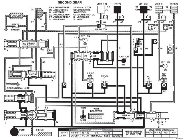
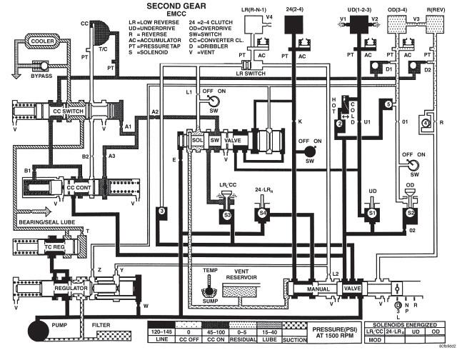
2 This provides the torque output for first gear. The other planetary gearset components are freewheeling. The first gear ratio is 2.84:1. SECOND GEAR POWERFLOW Second gear is achieved by having both planetary gear sets contribute to torque multiplication. As in first gear, torque input is through the underdrive clutch (1) to the rear sun gear. The 2/4 clutch (2) is applied to hold the front sun gear stationary. The rotating rear sun gear turns the rear planetary pinions. The rear pinions rotate the rear annulus/front carrier assembly. The pinions of the front carrier walk around the stationary front sun gear. This transmits torque to the front annulus/rear carrier assembly, which provides output torque and a gear ratio of 1.57:1. 2
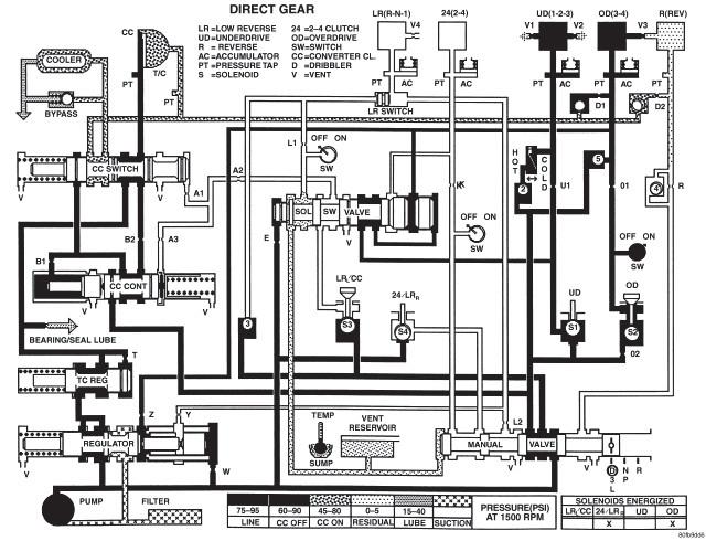
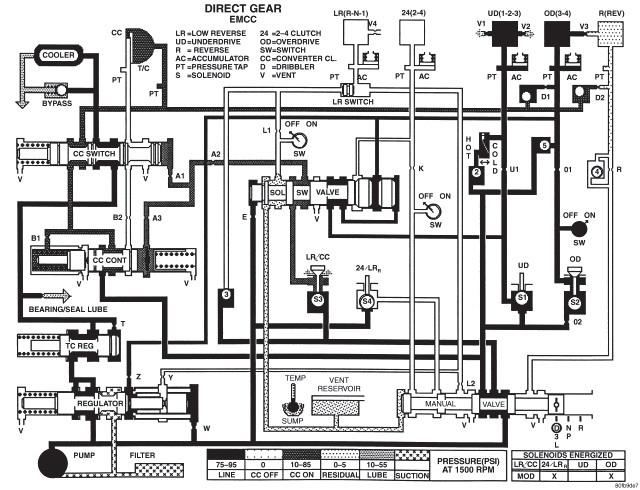
3 THIRD GEAR POWERFLOW In third gear, two input clutches are applied to provide torque input: the underdrive clutch (1) and overdrive clutch (2). The underdrive clutch rotates the rear sun gear, while the overdrive clutch rotates the front carrier/rear annulus assembly. The result is two components (rear sun gear and rear annulus gear) rotating at the same speed and in the same direction. This effectively locks the entire planetary gearset together and is rotated as one unit. The gear ratio in third is 1:1. 3
4 FOURTH GEAR POWERFLOW In fourth gear input torque is through the overdrive clutch (1) which drives the front carrier. The 2/4 clutch (2) is applied to hold the front sun gear. As the overdrive clutch rotates the front carrier, it causes the pinions of the front carrier to walk around the stationary front sun gear. This causes the front carrier pinions to turn the front annulus/rear carrier assembly which provides output torque. In fourth gear, transmission output speed is more than engine input speed. This situation is called overdrive and the gear ratio is 0.69:1. 4
5 REVERSE GEAR POWERFLOW In reverse, input power is through the reverse clutch (1). When applied, the reverse clutch drives the front sun gear through the overdrive hub and shaft. The L/R clutch (2) is applied to hold the front carrier/rear annulus assembly stationary. The front carrier is being held by the L/R clutch so the pinions are forced to rotate the front annulus/rear carrier assembly in the reverse direction. Output torque is provided, in reverse, with a gear ratio of 2.21:1. 5
 21 - Transmission and Transfer Case/Automatic -")
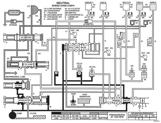
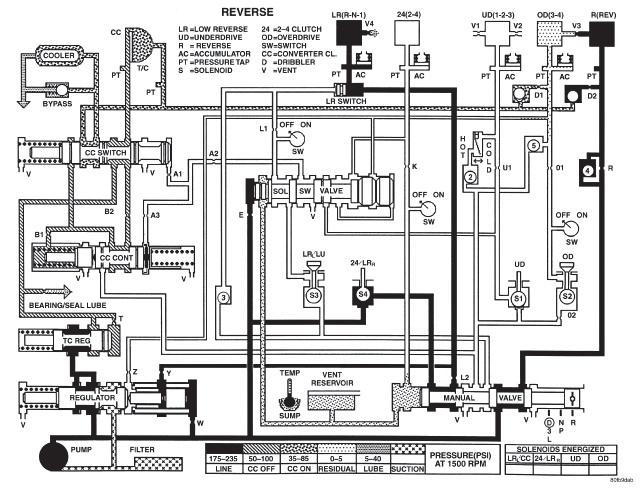
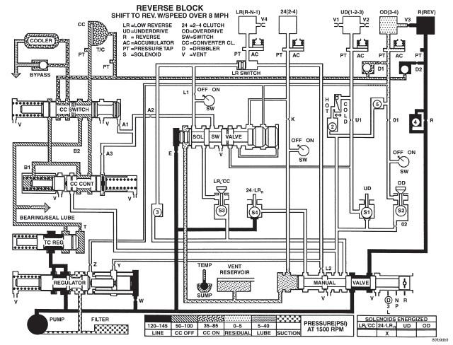
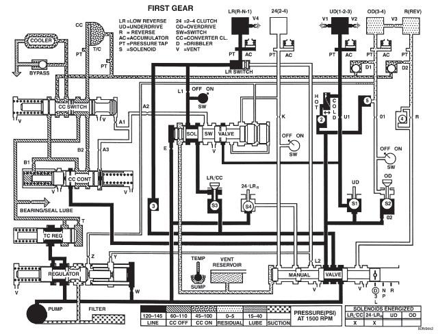
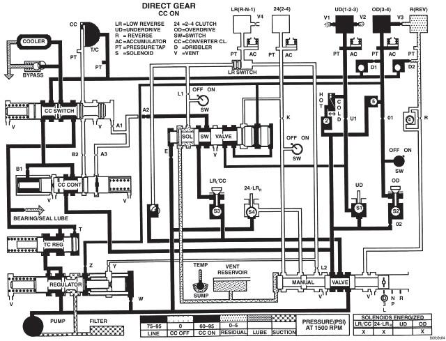
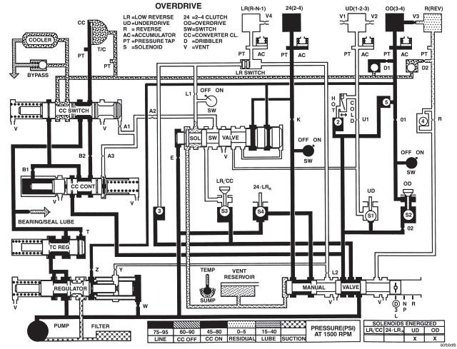
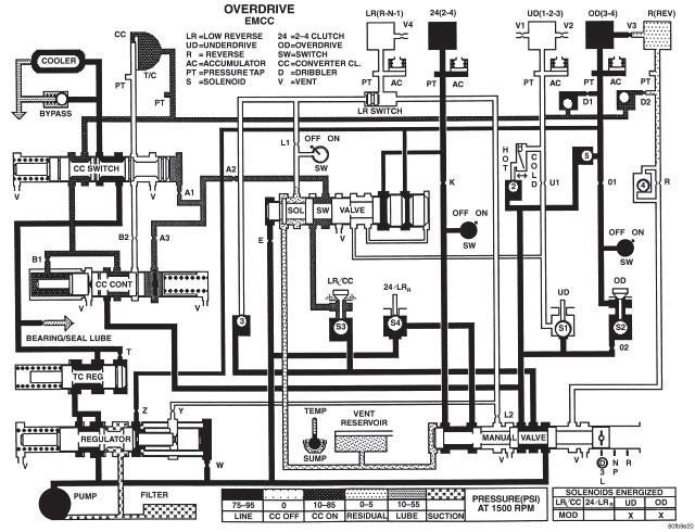
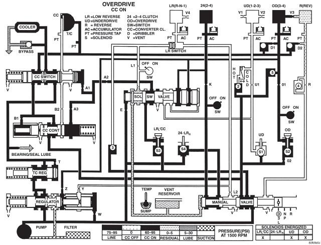
6 TJ - JEEP WRANGLER - 4.0L 6 CYL (MPI) 21 - Transmission and Transfer Case/Automatic - 42RLE/Schematics and Diagrams SCHEMATICS AND DIAGRAMS 1
7 2
8 3
9 4
10 5
11 6
12 7
13 8
14 9
15 10
16 11
17 12
18 13
 21 - Transmission and Transfer Case/Automatic - 42RLE/Diagnosis and Testing DIAGNOSIS AND TESTING - HYDRAULIC PRESSURE TESTS Pressure testing is a very important step in the diagnostic")
19 TJ - JEEP WRANGLER - 4.0L 6 CYL (MPI) 21 - Transmission and Transfer Case/Automatic - 42RLE/Diagnosis and Testing DIAGNOSIS AND TESTING - HYDRAULIC PRESSURE TESTS Pressure testing is a very important step in the diagnostic procedure. These tests usually reveal the cause of most transmission problems. Before performing pressure tests, be certain that fluid level and condition, and shift cable adjustments have been checked and approved. Fluid must be at operating temperature,150 to 200 degrees F. ( degrees C.). Install an engine tachometer, raise vehicle on hoist which allows the wheels to turn, and position tachometer so it can be read. Using special adapters L-4559A, attach 300 psi gauge(s) C-3293-SP to the port(s) required for test being conducted. Test port locations are shown in the Pressure Taps graphic. TEST ONE - SELECTOR IN MANUAL 1 (1st Gear) NOTE: This test checks pump output, pressure regulation and condition of the low/reverse clutch hydraulic circuit and shift schedule. 1. Attach pressure gauge to the low/reverse clutch tap. 2. Move selector lever to the MANUAL 1 position. 3. Allow vehicle wheels to turn and increase throttle opening to achieve an indicated vehicle speed to 20 mph. 4. Low/reverse clutch pressure should read 115 to 145 psi. TEST TWO - SELECTOR IN MANUAL 2 (Second Gear) NOTE: This test checks the underdrive clutch hydraulic circuit as well as the shift schedule. 1. Attach gauge to the underdrive clutch tap. 2. Move selector lever to the MANUAL 2 position. 3. Allow vehicle wheels to turn and increase throttle opening to achieve an indicated vehicle speed of 30 mph. 4. In second gear the underdrive clutch pressure should read 110 to 145 psi. TEST TWO A - SELECTOR IN DRIVE (OD ON - Fourth Gear) NOTE: This test checks the underdrive clutch hydraulic circuit as well as the shift schedule. 1
20 1. Attach gauge to the underdrive clutch tap. 2. Move selector lever to the DRIVE position. Verfy that the OD switch is ON. 3. Allow wheels to rotate freely and increase throttle opening to achieve an indicated speed of 40 mph. 4. Underdrive clutch pressure should read below 5 psi. If not, than either the solenoid assembly or controller is at fault. TEST THREE - SELECTOR IN DRIVE (OD OFF - Third and Second Gear) NOTE: This test checks the overdrive clutch hydraulic circuit as well as the shift schedule. 1. Attach gauge to the overdrive clutch tap. 2. Move selector lever to the DRIVE position. 3. Allow vehicle wheels to turn and increase throttle opening to achieve an indicated vehicle speed of 20 mph. 4. Overdrive clutch pressure should read 74 to 95 psi. 5. Move selector lever to the DRIVE position and increase indicated vehicle speed to 30 mph. 6. The vehicle should be in second gear and overdrive clutch pressure should be less than 5 psi. TEST FOUR - SELECTOR IN DRIVE (OD ON - Fourth Gear) NOTE: This test checks the 2/4 clutch hydraulic circuit. 1. Attach gauge to the 2/4 clutch tap. 2. Move selector lever to the DRIVE position. 3. Allow vehicle front wheels to turn and increase throttle opening to achieve an indicated vehicle speed of 30 mph. Vehicle should be in fourth gear. 4. The 2/4 clutch pressure should read 75 to 95 psi. TEST FIVE-SELECTOR IN DRIVE (OD ON - Fourth Gear, CC on) NOTE: These tests check the torque converter clutch hydraulic circuit. 1. Attach gauge to the torque converter clutch off pressure tap. 2. Move selector lever to the DRIVE position. 3. Allow vehicle wheels to turn and increase throttle opening to achieve an indicated vehicle speed of 50 mph. Vehicle should be in 4th gear, CC on. CAUTION: Both wheels must turn at the same speed. 4. Torque converter clutch off pressure should be less than 5 psi. 5. Now attach the gauge to the torque converter clutch on pressure tap. 2
21 6. Move selector to the OD position. 7. Allow vehicle wheels to turn and increase throttle opening to achieve an indicated vehicle speed of 50 mph. 8. Verify the torque converter clutch is applied mode using the RPM display of the DRB scan tool. 9. Torque converter clutch on pressure should be psi. TEST SIX-SELECTOR IN REVERSE NOTE: This test checks the reverse clutch hydraulic circuit. 1. Attach gauge to the reverse and low/reverse clutch tap. 2. Move selector lever to the REVERSE position. 3. Read reverse clutch pressure with output stationary (foot on brake) and throttle opened to achieve 1500 rpm. 4. Reverse and low/reverse clutch pressure should read 165 to 235 psi. TEST RESULT INDICATIONS 1. If proper line pressure is found in any one test, the pump and pressure regulator are working properly. 2. Low pressure in all positions indicates a defective pump, a clogged filter, or a stuck pressure regulator valve. 3. Clutch circuit leaks are indicated if pressures do not fall within the specified pressure range. 4. If the overdrive clutch pressure is greater than 5 psi in 6 of Test Three, a worn reaction shaft seal ring or a defective solenoid assembly is indicated. 5. If the underdrive clutch pressure is greater than 5 psi in 4 of Test Two-A, a defective solenoid/pressure switch assembly or controller is the cause. ALL PRESSURE SPECIFICATIONS ARE PSI (on hoist, with wheels free to turn) Gear Selector Position Actual Gear UnderdriveOverdrive Reverse Clutch Clutch Clutch PRESSURE TAPS Torque Torque Converter Converter Clutch Clutch Off On 2/4 Clutch Low/ Reverse Clutch PARK - 0 mph * PARK REVERSE - 0 mph * REVERSE NEUTRAL - 0 mph * NEUTRAL Low - 20 mph # FIRST Third - 30 mph # SECOND Third - 45 mph # DIRECT OD - 30 mph # OVERDRIVE
22 Gear Selector Position Actual Gear UnderdriveOverdrive Reverse Clutch Clutch Clutch PRESSURE TAPS Torque Torque Converter Converter Clutch Clutch Off On 2/4 Clutch Low/ Reverse Clutch OD - 50 mph # OVERDRIVE WITH TCC * Engine Speed at 1500 rpm # CAUTION: Both wheels must be turning at same speed. 4
23 TJ - JEEP WRANGLER - 4.0L 6 CYL (MPI) 21 - Transmission and Transfer Case/Automatic - 42RLE/ASSEMBLY, Transmission Solenoid and Pressure Switch/ Operation OPERATION SOLENOIDS The solenoids receive electrical power from the Transmission Control Relay through a single wire. The TCM energizes or operates the solenoids individually by grounding the return wire of the solenoid needed. When a solenoid is energized, the solenoid valve shifts, and a fluid passage is opened or closed (vented or applied), depending on its default operating state. The result is an apply or release of a frictional element. The 2/4 and UD solenoids are normally applied, which allows fluid to pass through in their relaxed or off state. By design, this allows transmission limp-in (P,R,N,2) in the event of an electrical failure. The continuity of the solenoids and circuits are periodically tested. Each solenoid is turned on or off depending on its current state. An inductive spike should be detected by the TCM during this test. If no spike is detected, the circuit is tested again to verify the failure. In addition to the periodic testing, the solenoid circuits are tested if a speed ratio or pressure switch error occurs. PRESSURE SWITCHES The TCM relies on three pressure switches to monitor fluid pressure in the L/R, 2/4, and OD hydraulic circuits. The primary purpose of these switches is to help the TCM detect when clutch circuit hydraulic failures occur. The range for the pressure switch closing and opening points is psi. Typically the switch opening point will be approximately one psi lower than the closing point. For example, a switch may close at 18 psi and open at 17 psi. The switches are continuously monitored by the TCM for the correct states (open or closed) in each gear as shown in the following chart: PRESSURE SWITCH STATES GEAR L/R 2/4 OD R OP OP OP P/N CL OP OP 1st CL OP OP 2nd OP CL OP D OP OP CL OD OP CL CL OP = OPEN CL = CLOSED A Diagnostic Trouble Code (DTC) will set if the TCM senses any switch open or closed at the wrong time in a given gear. The TCM also tests the 2/4 and OD pressure switches when they are normally off (OD and 2/4 are tested in 1st gear, OD in 2nd gear, and 2/4 in 3rd gear). The test simply verifies that they are operational, by looking for a closed state when the corresponding element is applied. Immediately after a shift into 1st, 2nd, or 3rd gear with the engine speed 1
24 above 1000 rpm, the TCM momentarily turns on element pressure to the 2/4 and OD clutch circuits to identify that the appropriate switch has closed. If it doesn't close, it is tested again. If the switch fails to close the second time, the appropriate Diagnostic Trouble Code (DTC) will set. 2
25 TJ - JEEP WRANGLER - 4.0L 6 CYL (MPI) 21 - Transmission and Transfer Case/Automatic - 42RLE/SENSOR, Speed, Output/Operation OPERATION The Input Speed Sensor provides information on how fast the input shaft is rotating. As the teeth of the input clutch hub pass by the sensor coil, an AC voltage is generated and sent to the TCM. The TCM interprets this information as input shaft rpm. The Output Speed Sensor generates an AC signal in a similar fashion, though its coil is excited by rotation of the rear planetary carrier lugs. The TCM interprets this information as output shaft rpm. The TCM compares the input and output speed signals to determine the following: Transmission gear ratio Speed ratio error detection CVI calculation The TCM also compares the input speed signal and the engine speed signal to determine the following: Torque converter clutch slippage Torque converter element speed ratio 1
AUTOMATIC TRANSMISSION - 42RLE
 TJ AUTOMATIC TRANSMISSION - 42RLE 21-37 AUTOMATIC TRANSMISSION - 42RLE TABLE OF CONTENTS page AUTOMATIC TRANSMISSION - 42RLE DESCRIPTION...38 OPERATION...40 DIAGNOSIS AND TESTING DIAGNOSIS AND TESTING
LX AUTOMATIC TRANSMISSION NAG1 - SERVICE INFORMATION TABLE OF CONTENTS
 LX AUTOMATIC TRANSMISSION NAG1 - SERVICE INFORMATION 21-495 AUTOMATIC TRANSMISSION NAG1 - SERVICE INFORMATION TABLE OF CONTENTS page AUTOMATIC TRANSMISSION NAG1 - SERVICE INFORMATION DESCRIPTION...496
2011 Dodge or Ram Truck RAM 3500 Truck 4WD L6-6.7L DSL Turbo
 1 of 10 10/14/2013 9:23 AM 2011 Dodge or Ram Truck RAM 3500 Truck 4WD L6-6.7L DSL Turbo Vehicle» A L L Diagnostic Trouble Codes ( DTC )» Testing and Inspection» P Code Charts» P0732 P0732-GEAR RATIO ERROR
DIAGNOSIS AND TESTING
 307-01-1 Automatic Transaxle/Transmission 307-01-1 DIAGNOSIS AND TESTING Special Testing Procedures Special Tool(s) Air Test Plate, Transmission 307-405 Transmission Fluid Pressure Gauge 307-004 (T57L-77820-A)
INTRODUCTION PRELIMINARY DIAGNOSIS
 NO: 21-11-98 SUBJECT: Transmission Simulator Diagnostic Tool DATE: Dec. 11, 1998 NOTE: THIS INFORMATION APPLIES TO VEHICLES EQUIPPED WITH A 45RFE TRANSMISSION. DISCUSSION: A new transmission simulator
6T30/6T40/6T45 - AUTOMATIC TRANSMISSION
 2010 GMC Truck Terrain AWD L4-2.4L Vehicle > ALL Diagnostic Trouble Codes ( DTC ) > Testing and Inspection > P Code Charts > P0717 6T30/6T40/6T45 - AUTOMATIC TRANSMISSION DTC P0716 or P0717 Diagnostic
DIAGNOSIS AND TESTING
 307-01B-1 DIAGNOSIS AND TESTING Special Testing Procedures The special tests are designed to aid the technician in diagnosing the hydraulic and mechanical portion of the transmission. Engine Idle speed
P0750-LR SOLENOID CIRCUIT
 9 - JS - DGE AVENGER -.L CYL DOHC V DUAL V.V.T. P-LR CIRCUIT BATT A B(+) CONTROL OUTPUT ELECTRONICS TOTALLY INTEGRATED POWER C T S T C T C T S T - - UD / T T YL/TN YL/DG T9 DG/TN T9 T T9 T YL/DB DG/WT
2002 Jeep Grand Cherokee Limited AUTOMATIC TRANSMISSIONS 45RFE & 545RFE Diagnosis - Except Next Generation Controller
 APPLICATION 2002 AUTOMATIC TRANSMISSIONS 45RFE & 545RFE Diagnosis - Except Next Generation Controller For 2002 1/2 Chrysler models equipped with new control module (referred to as "Next Generation Controller"),
Special Testing Procedures
 SECTION 307-01: Automatic Transaxle/Transmission 5R55S 2009 Mustang Workshop Manual DIAGNOSIS AND TESTING Procedure revision date: 06/30/2009 Special Testing Procedures Special Tool(s) Air Test Plate and
P0777-SECONDARY PRESSURE SOLENOID STUCK ON (LOW PRESSURE)
") 009 - MK - JEEP COMPASS/PATRIOT -.0L 4 CYL DOHC 6V DUAL V.V.T. P0777-SECONDARY STUCK ON (LOW ) / LINE SECONDARY ON/OFF 3 4 T0 DG/LB T9 T9 T60 YL/DB YL/LB YL/GY C C 3 C 4 C LINE SECONDARY ON/OFF MODULE-
009 - MK - JEEP COMPASS/PATRIOT -.0L 4 CYL DOHC 6V DUAL V.V.T. P0777-SECONDARY STUCK ON (LOW ) / LINE SECONDARY ON/OFF 3 4 T0 DG/LB T9 T9 T60 YL/DB YL/LB YL/GY C C 3 C 4 C LINE SECONDARY ON/OFF MODULE-
P0750-LR SOLENOID CIRCUIT
 2008 Dodge Pickup 4.7L Eng R1500 P0750-LR SOLENOID CIRCUIT Circuit Schematic Fig 1: Transmission Solenoid/TRS Assembly Circuit Schematic Courtesy of CHRYSLER LLC Additional Wiring For complete wiring diagrams
Shift Solenoid B (SSB) and Shift Solenoid D (SSD) Inverse Proportional VFS 2761
 and Shift Solenoid D (SSD) Inverse Proportional VFS 2761") Item Description 1 Shift Solenoid A (SSA) Variable Force Solenoid (VFS) 2 Shift Solenoid C (SSC) VFS SSB and SSD use inverse proportional operation. As the current from the PCM decreases, the pressure
Item Description 1 Shift Solenoid A (SSA) Variable Force Solenoid (VFS) 2 Shift Solenoid C (SSC) VFS SSB and SSD use inverse proportional operation. As the current from the PCM decreases, the pressure
P0750-LR SOLENOID CIRCUIT
 6 - HB - DODGE DURANGO - 5.7L HEMI V - MDS P75-LR CIRCUIT BATT A FUSE 5 5A INTEGRATED POWER 5-6 7 C 7 C 9 C4 Z95 T5 BK YL/BK 4 G T C T S T T TO OTHER MODULES /TRS 7 9 7 T5 YL/BK T T T T6 YL/RD T DG T9
AISIN WARNER. 1. With the selector lever in Park, start the engine and warm it to operating temperature.
 AISIN WARNER 249 Manual Code Retrieval Preliminary Test: 1. With the selector lever in Park, start the engine and warm it to operating temperature. 2. Turn the ignition switch to the Off position, then
Mercedes Presented by Dr William (Bill) Henney PhD F.I.M.I
 Henney PhD F.I.M.I") Mercedes 722.9 Presented by Dr William (Bill) Henney PhD F.I.M.I Features Electronically Controlled Automatic Gearbox 7 Forward and 2 Reverse Gears Transmission Control Module is : Integrated into the
Mercedes 722.9 Presented by Dr William (Bill) Henney PhD F.I.M.I Features Electronically Controlled Automatic Gearbox 7 Forward and 2 Reverse Gears Transmission Control Module is : Integrated into the
P0882-TCM POWER INPUT LOW
 - JK - JEEP WRANGLER - L V6 (SMPI) P-TCM POWER INPUT LOW BATTERY BATT A FUSE J 5A POWER DIESEL GAS Z 6 BK Z 4 BK Z 6 BK 5 7A 7 6 ELECTRONICS 6 C C T6 6 T5 YL/OR YL/BR 5 C C T6 6 T5 YL/OR YL/BR S6 T6 T6
Automatic Transmission Basics
 Section 1 Automatic Transmission Basics Lesson Objectives 1. Describe the function of the torque converter. 2. Identify the three major components of the torque converter that contribute to the multiplication
TRANSMISSION - NGC. Symptom: P0706-CHECK SHIFTER SIGNAL. When Monitored and Set Condition:
 Symptom: P0706-CHECK SHIFTER SIGNAL When Monitored and Set Condition: P0706-CHECK SHIFTER SIGNAL When Monitored: Continuously with the ignition on. Set Condition: After 3 occurrences in one ignition cycle
P0706-TRANSMISSION RANGE SENSOR RATIONALITY
 Page 1 of 7 28 - DTC-Based Diagnostics/MODULE, Powertrain Control (PCM), 545RFE/Diagnosis and Testing P0706-TRANSMISSION RANGE SENSOR RATIONALITY Special Tools: Click to display a list of tools used in
P0760-OD SOLENOID CIRCUIT
 - JC - DGE JOURNEY -.5L V6 V MPI - HIGH OUTPUT P6- CIRCUIT BATT A RELAY-PCM MULE- TOTALLY INTEGRATED POWER A FUSE J A 6 C T6 6 C T6 D C5 T6 S T6 6 L/R / /TRS EMCC VFS C LR UD 6 5 T6 T6 T6 T5 T T T T YL/TN
NOTE: Clean and inspect all components. Replace any components which show evidence of excessive wear or scoring.
 21 - Transmission and Transfer Case/Automatic - 68RFE/Assembly ASSEMBLY Labor Operations: Click to display a list of Labor Operations associated with this procedure Special Tools: Click to display a list
TION AND OPERATION Procedure revision date: 01/22/1999
 TION AND OPERATION Procedure revision date: 01/22/1999 Main Components and Functions AX4S Main Components http://www.fordtechservice.dealerconnection.com/pubs/content/~wsww/~mus~len/20/sww71006.htm (1
Technical Service Bulletin
 Subject ATA SOLENOID DIAGNOSTIC CODES P0740, P0741, P0742, P0743, P0746, P0748, P0750, P0755, P0760, P0765, P0770 Date Model [X] PARTS MANAGER JANUARY, 2006 1999~ SONATA, 2001~ ELANTRA, SANTA FE & XG,
AUTOMATIC TRANSMISSIONS. General Motors Corp. Hydra-Matic 4L60-E Overhaul
 1997-98 AUTOMATIC TRANSMISSIONS General Motors Corp. Hydra-Matic 4L60-E Overhaul APPLICATION TRANSMISSION APPLICATIONS Application Corvette Transaxle 4L60-E IDENTIFICATION The 4L60-E transmission can be
MEDIUM DUTY TRUCK. Presented By. ATSG s PETE LUBAN
 MEDIUM DUTY TRUCK Presented By ATSG s PETE LUBAN 1/3/2M WWW.ATSG.COM 2/3/1M 3/3 1000/2000 SERIES Transmission code identification PPT 1 0 0 0 MHS HS Highway Series MHS Motor Home Series EVS Emergency Vehicle
TRANSMISSION SPECIFICS VALVE BODY COMPONENTS
 TRANSMISSION SPECIFICS VALVE BODY COMPONENTS Valve body electrical components consist of: Pressure Regulator solenoids (EDS). Controlled by a Pulse Width Modulated (PWM) control signal from the TCM provides
 Page 1 of 10 Main Components and Functions Torque Converter 1 Cover (Part of 7902) 2 Converter Damper Plate 3 O-Ring (Part of 7902) 4 Turbine Assembly (Part of 7902) 5 Selective Spacer 6 Thrust Washer
Transmissions. Service Training Course No. 200 WARNING: WHILE SERVICING AND TESTING VEHICLES AND VEHICLE SYSTEMS, TAKE ALL
 Service Training Course No. 200 Transmissions This publication is intended for instructional purposes only. Always refer to the appropriate Jaguar Service publication for specific details and procedures.
ZF4HP16. Technical Bulletin # Signal Combination L1 L2 L3 L4 P R N D
 Transmission: Subject: Application: Issue Date: Technical Bulletin # 1308 ZF4HP16 Electronical Components Description 2005 Suzuki Forenza L4-2.0L February, 2010 ZF4HP16 Electronical Components Description
OIL CIRCUIT DIAGRAMS:
 Toyota U660-E WWW.ATSG.BIZ INDE Introduction... 2 Component Application Chart... 4 Sprag Rotation... 5 Pressure Testing... 6 Fluid Specification... 8 Transmission Range Sensor... 10 TCM Location... 13
HYDRAULIC PRESSURE SWITCH CIRCUIT
 Symptom: P1726-UD HYDRAULIC PRESSURE SWITCH CIRCUIT When Monitored and Set Condition: P1726-UD HYDRAULIC PRESSURE SWITCH CIRCUIT When Monitored: In any forward gear with engine speed above 1000 RPM shortly
TRANSMISSION AND TRANSFER CASE
 WJ TRANSMISSION AND TRANSFER CASE 21-1 TRANSMISSION AND TRANSFER CASE CONTENTS page page 44RE AUTOMATIC TRANSMISSION... 1 NV247 TRANSFER CASE... 129 44RE AUTOMATIC TRANSMISSION INDEX page GENERAL INFORMATION
2007 Dodge Nitro R/T
 ASSEMBLY AUTOMATIC TRANSMISSION - 42RLE NOTE: If the transmission assembly is being reconditioned (clutch/seal replacement) or replaced, it is necessary to perform the TCM QUICK LEARN Procedure using the
Geo Prizm ( LSi) Toyota Celica 1.8L (1994)
 Toyota Celica 1.8L (1994)") Page 1 of 140 ARTICLE BEGINNING APPLICATION TRANSMISSION APPLICATIONS Application Geo Prizm (1993-94 LSi) Toyota Celica 1.6L (1993) Celica 1.8L (1994) Celica 2.2L (1993) Corolla 1.8L MR2 Paseo Transaxle
Page 1 of 140 ARTICLE BEGINNING APPLICATION TRANSMISSION APPLICATIONS Application Geo Prizm (1993-94 LSi) Toyota Celica 1.6L (1993) Celica 1.8L (1994) Celica 2.2L (1993) Corolla 1.8L MR2 Paseo Transaxle
Troubleshooting the Transmission Hydraulic System
 Testing and Adjusting IT28F INTEGRATED TOOLCARRIER POWER TRAIN Testing And Adjusting Introduction Reference: For Specifications with illustrations, refer to SENR5974, IT28F Integrated Toolcarrier Power
Powertrain DTC Summaries EOBD
 Powertrain DTC Summaries Quick Reference Diagnostic Guide Jaguar X-TYPE 2.0 L 2002.25 Model Year Refer to page 2 for important information regarding the use of Powertrain DTC Summaries. Jaguar X-TYPE 2.0
AUTOMATIC TRANSMISSIONS Mitsubishi F3A20 Series TRANSMISSION APPLICATION TABLE
 Article Text ARTICLE BEGINNING AUTOMATIC TRANSMISSIONS Mitsubishi F3A20 Series APPLICATION TRANSMISSION APPLICATION TABLE Vehicle Application Transmission Model Colt 3-Speed (1990-94)... F3A21 Colt Vista
P0733 DTC P0733 A/T 3RD GEAR FUNCTION
 2003 Nissan-Datsun Altima L4-2.5L (QR25DE) Vehicle > ALL Diagnostic Trouble Codes ( DTC ) > Testing and Inspection > P Code Charts P0733 DTC P0733 A/T 3RD GEAR FUNCTION Description - This is an OBD-II
STARTING SYSTEMS 8B - 1 STARTING SYSTEMS CONTENTS
 TJ STARTING SYSTEMS 8B - 1 STARTING SYSTEMS CONTENTS page DESCRIPTION AND OPERATION STARTER MOTOR... 2 STARTER RELAY... 3 STARTING SYSTEM... 1 DIAGNOSIS AND TESTING STARTER MOTOR... 8 STARTER MOTOR NOISE
PRESSURE SWITCH SENSE CIRCUIT
 Symptom: P0876-UD PRESSURE SWITCH SENSE CIRCUIT When Monitored and Set Condition: P0876-UD PRESSURE SWITCH SENSE CIRCUIT When Monitored: Whenever the engine is running. Set Condition: This DTC is set if
Diagnostic Trouble Code (DTC) Charts
 Charts") SECTION 307-01: Automatic Transaxle/Transmission 5R55S 2009 Mustang Workshop Manual DIAGNOSIS AND TESTING Procedure revision date: 06/30/2009 Diagnostic Trouble Code (DTC) Charts DTC Chart **May also be
SECTION 307-01: Automatic Transaxle/Transmission 5R55S 2009 Mustang Workshop Manual DIAGNOSIS AND TESTING Procedure revision date: 06/30/2009 Diagnostic Trouble Code (DTC) Charts DTC Chart **May also be
Aisin Warner LE 1998-Up Nissan UD Isuzu RNJ Mitsubishi FUSO
 Aisin Warner 450-43LE 1998-Up Nissan UD Isuzu RNJ Mitsubishi FUSO AISIN SEIKI CO., LTD. SERIAL NO. 9A0001 Year: 1999 Month: January Ex. B: February C: March D: April * * L: December Serial Numbers Component
INDEX BACK AUTOMATIC TRANSMISSION SERVICE GROUP SW 107TH AVENUE MIAMI, FLORIDA (305) Copyright ATSG 2005
 Copyright ATSG 2005") BACK INDEX MITSUBISHI F4A4, F4A42, F4A5 IDENTIFICATION CODE STAMPING LOCATION... GEAR RATIO IDENTIFICATION... INTERNAL COMPONENT AND SOLENOID APPLICATION CHART... FLUID REQUIREMENTS... CASE CONNECTOR TERMINAL
BACK INDEX MITSUBISHI F4A4, F4A42, F4A5 IDENTIFICATION CODE STAMPING LOCATION... GEAR RATIO IDENTIFICATION... INTERNAL COMPONENT AND SOLENOID APPLICATION CHART... FLUID REQUIREMENTS... CASE CONNECTOR TERMINAL
DIAGNOSTIC TROUBLE CODE DEFINITIONS
 DIAGNOSTIC TROUBLE CODE DEFINITIONS DIAGNOSTIC TROUBLE CODE DEFINITIONS DTC Description P0010 Variable Valve Timing Circuit Malfunction (Bank 1) P0020 Variable Valve Timing Circuit Malfunction (Bank 2)
G - TESTS W/CODES - 2.2L
 G - TESTS W/CODES - 2.2L 1994 Toyota Celica 1994 ENGINE PERFORMANCE Toyota 2.2L Self-Diagnostics Celica INTRODUCTION If no faults were found while performing F - BASIC TESTING, proceed with self-diagnostics.
DIAGNOSIS AND TESTING
 307-01-1 Automatic Transaxle/Transmission 307-01-1 DIAGNOSIS AND TESTING Diagnostic Trouble Code Charts Diagnostic Trouble Code Chart P0102, MAF MAF concerns MAF system High/low EPC REFER to the P0103,
2007 Jeep Truck Liberty 4WD V6 3.7L VIN K
 2007 Jeep Truck Liberty 4WD V6 3.7L VIN K Vehicle» Transmission and Drivetrain» Automatic Transmission/Transaxle» Service and Repair» Overhaul» Disassembly DISASSEMBLY NOTE: If the transmission is being
SECTION Electronic Engine Controls
 303-14-i Electronic Engine Controls 303-14-i SECTION 303-14 Electronic Engine Controls CONTENTS PAGE DIAGNOSIS AND TESTING Electronic Engine Controls... 303-14-2 DTC Charts... 303-14-2 303-14-2 Electronic
P0876-UD PRESSURE SWITCH RATIONALITY
 Page 1 of 14 P0876-UD PRESSURE SWITCH RATIONALITY Page 2 of 14 For a complete wiring diagram Refer to Section 8W When Monitored: Continuously with the ignition on and engine running. Set Condition: This
P0743-TCC SOLENOID CIRCUIT
 - XK - JEEP COMMANDER -.L MAGNUM V P-TCC CIRCUIT RUN-START F JUNCTION BLOCK FUSE A ELECTRO RELAY- - - SHIFT TCC -/ -5 SUPPLY VOLTAGE MODULATION HYDRAULIC UNIT (.L/DIESEL) T T T T5 T T T 5 A /LG DG/ C Z
2007 Jeep Truck Liberty 4WD V6 3.7L VIN K
 2007 Jeep Truck Liberty 4WD V6 3.7L VIN K Vehicle» Transmission and Drivetrain» Automatic Transmission/Transaxle» Service and Repair» Overhaul» Assembly ASSEMBLY NOTE: If the transmission assembly is being
1. Range Reference Chart
 . Range Reference Chart Range Gear Sol A N.C. Sol B N.C. O/D Roller Clutch Overrun Clutch (OC) Fouth Clutch (C4) Third Clutch (C) Reverse Clutch (RC) Second Clutch (C) Principle Sprag Assembly Band Assembly
Kit Number Used with the TE Transmission Simula. Reference Guide /05/06
 62TE Transmission Simula ulator Adapter Harness Manual Kit Number 9944 Used with the 8333 Transmission Simulator Reference Guide 541263 12/05/06 Copyright 2006 by SPX Corporation INTRODUCTION The following
SECTION 5 DIAGNOSTIC TROUBLE CODES (DTC)
") 5 1. DTC MEMORY SECTION 5 Diagnostic Trouble Codes (DTCs) are logged in a list in TCM memory. The DTCs contained in the list have information recorded as shown in Table 5 1 (DTC example). The TCM is capable
5 1. DTC MEMORY SECTION 5 Diagnostic Trouble Codes (DTCs) are logged in a list in TCM memory. The DTCs contained in the list have information recorded as shown in Table 5 1 (DTC example). The TCM is capable
VALVE BODY. Shift Pressure Control Solenoid Valve. 1. Leaf spring 2. Contact spring 3. Conductor track 4. O-ring 5. O-ring 6.
 72 3650 VALVE BODY Shift Pressure Control Solenoid Valve 8 9 7 7 A B C D 10 7 E F 1. Leaf spring 2. Contact spring 3. Conductor track 4. O-ring 5. O-ring 6. Shift plate 7. Leaf spring and socket bolt 8.
PRE CHECK DI 456. w/ Tachometer. w/o Tachometer. Hand held Tester AUTOMATIC TRANSMISSION (A340E, A340F) 2003 TOYOTA TACOMA (RM1002U) D10837 D00729
 2003 TOYOTA TACOMA (RM1002U) D10837 D00729") DI456 w/ Tachometer w/o Tachometer D10837 PRECHECK DI8Z403 1. DIAGNOSIS SYSTEM (a) Description When troubleshooting OBD II vehicles, the only difference from the usual troubleshooting procedure is that
DI456 w/ Tachometer w/o Tachometer D10837 PRECHECK DI8Z403 1. DIAGNOSIS SYSTEM (a) Description When troubleshooting OBD II vehicles, the only difference from the usual troubleshooting procedure is that
HYDRAULIC PRESSURE SWITCH CIRCUIT
 Symptom: P1787-OD HYDRAULIC PRESSURE SWITCH CIRCUIT When Monitored and Set Condition: P1787-OD HYDRAULIC PRESSURE SWITCH CIRCUIT When Monitored: In any forward gear with engine speed above 1000 RPM shortly
TCU 1) CONNECTOR INFORMATION 2) CONNECTOR IDENTIFICATION SYMBOL & PIN NUMBER POSITION CIRCUIT ACTYON
 CONNECTOR INFORMATION 2) CONNECTOR IDENTIFICATION SYMBOL & PIN NUMBER POSITION CIRCUIT ACTYON") 311001 017 311001 TCU 1) CONNECTOR INFORMATION 2) CONNECTOR IDENTIFICATION SYMBOL & PIN NUMBER POSITION 018 311001 (3) DESCRIPTION A. ION (BTRA) M74 4WD AUTOMATIC TRANSMISSION The ION (BTR) Four Speed
311001 017 311001 TCU 1) CONNECTOR INFORMATION 2) CONNECTOR IDENTIFICATION SYMBOL & PIN NUMBER POSITION 018 311001 (3) DESCRIPTION A. ION (BTRA) M74 4WD AUTOMATIC TRANSMISSION The ION (BTR) Four Speed
U140E AND U241E AUTOMATIC TRANSAXLE
 CH-125 U140E AND U241E AUTOMATIC TRANSAXLE DESCRIPTI The 02 Camry line-up uses the following types of automatic transaxles: 2AZ-FE U241E 1MZ-FE U140E These automatic transaxles are compact and high-capacity
CHARGING SYSTEM 8C - 1 CHARGING SYSTEM CONTENTS
 TJ CHARGING SYSTEM 8C - 1 CHARGING SYSTEM CONTENTS page DESCRIPTION AND OPERATION BATTERY TEMPERATURE SENSOR... 2 CHARGING SYSTEM OPERATION... 1 ELECTRONIC VOLTAGE REGULATOR... 2 GENERATOR... 1 DIAGNOSIS
Diagnostic Procedures
 Diagnostic Procedures Lesson Objectives 1. Perform all preliminary checks prior to test driving. 2. Relate the importance that verifying the customer concern plays in diagnosis. 3. Explain the types of
NOTE: Clean and inspect all components. Replace any components which show evidence of excessive wear or scoring.
 ASSEMBLY (AUTOMATIC 545RFE)... ASSEMBLY NOTE: Apply trans jell or petroleum jelly to all slide portions, rolling contacts surfaces, thrust surfaces etc. to prevent burnout during initial operation. Lubricate
AUTOMATIC TRANSMISSION
 SECTION 5A AUTOMATIC TRANSMISSION CAUTION: isconnect the negative battery cable before removing or installing any electrical unit or when a tool or equipment could easily come in contact with exposed electrical
Technical Service Bulletin
 Technical Service Bulletin Group Number TRANSAXLE 07-40-009-1 Subject AUTOMATIC TRANSAXLE HARSH AND/OR DELAYED ENGAGEMENT INTO DRIVE OR REVERSE Date Model [X] PARTS MANAGER SEPTEMBER, 2007 1999~SONATA,
2007 Dodge Nitro R/T
 1 - TURBINE 2 - IMPELLER 2007 Dodge Nitro R/T CONVERTER-TORQUE DESCRIPTION TORQUE CONVERTER Fig. 267: Cutaway View Of Torque Converter Fig. 268: Impeller 2007 Dodge Nitro R/T 3 - STATOR 4 - INPUT SHAFT
ATASA 5 th Study Guide. Be Certain to Read the Summary Chapter 42 Pages Automatic Transmissions & Transaxle Service 31 Points
 ATASA 5 th Study Guide Be Certain to Read the Summary Chapter 42 Pages 1245 1270 Automatic Transmissions & Transaxle Service 31 Points 1. Prior to beginning any service work on a transmission, it correctly
Module 5: Cooling Fundamentals
 Terms and Definitions Major Mechanical Parts of a Four Speed Auto Transmission Parts of a Planetary Gear System Planetary Gear System Operation Speed, Torque, and Directional Function Fluid Pump and Pressure
Advanced Auto Tech Worksheet Auto Trans & Transaxle Chapter 40 Pages Points Due Date
 Advanced Auto Tech Worksheet Name Auto Trans & Transaxle Chapter 40 Pages 1173 1215 107 Points Due Date 1. Automatic transmissions are operated by hydraulics as well as electronics to select according
CHASSIS AUTOMATIC TRANSAXLE. Destination New Model Previous Model Change (from previous model)
") CHASSIS AUTOMATIC TRANSAXLE CH-37 U341E AUTOMATIC TRANSAXLE 1. General The compact and high-capacity 4-speed U341E automatic transaxle [Super ECT (Electronic Controlled Transaxle)] is used. The following
CHASSIS AUTOMATIC TRANSAXLE CH-37 U341E AUTOMATIC TRANSAXLE 1. General The compact and high-capacity 4-speed U341E automatic transaxle [Super ECT (Electronic Controlled Transaxle)] is used. The following
110% CUSTOMER SATISFACTION and Absolute BEST QUALITY!
 Chrysler 133 110% CUSTOMER SATISFACTION and Absolute BEST QUALITY! That s a promise with a 1 Year Guarantee on our Reconstructed Valve Bodies. Reconstructed with the Latest Because Valve Body PRO is customer
Shift Solenoid "B" Performance (Shift Solenoid Valve S2)
") 86 A750E AUTOMIC TRANSMISSION AUTOMIC TRANSMISSION SYSTEM DTC P0756 Shift Solenoid "B" Performance (Shift Solenoid Valve S2) DESCRIPTION The ECM uses signals from the output shaft speed sensor and input
86 A750E AUTOMIC TRANSMISSION AUTOMIC TRANSMISSION SYSTEM DTC P0756 Shift Solenoid "B" Performance (Shift Solenoid Valve S2) DESCRIPTION The ECM uses signals from the output shaft speed sensor and input
Powertrain DTC Summaries OBD II
 Powertrain DTC Summaries Quick Reference Diagnostic Guide Jaguar X-TYPE 2.5L and 3.0L 2002 Model Year Revised January, 2002: P0706, P0731, P0732, P0733, P0734, P0735, P0740, P1780 POSSIBLE CAUSES Revised
DIAGNOSIS AND TESTING
 307-01-1 Automatic Transaxle/Transmission 307-01-1 DIAGNOSIS AND TESTING Pinpoint Tests OSC Equipped Vehicle Special Tool(s) Transmission Fluid Pressure Gauge 307-004 (T57L-77820-A) Special Tool(s) MLP-TR
11.AWD Transfer System
 W1860BE.book Page 54 Tuesday, January 28, 2003 11:01 PM 11.AWD Transfer System A: MPT MODELS 1. GENERAL This all-wheel-drive (AWD) transfer system uses an electronically controlled multi-plate type transfer
1998 Ford F Diagnostics > Diagnostic Routines > Powertrain > Automatic Transmission > A... Page 1 of 63
 1998 Ford F-150 - Diagnostics > Diagnostic Routines > Powertrain > Automatic Transmission > A... Page 1 of 63 1998 Ford F-150 : Diagnostics > Diagnostic Routines > Powertrain > Automatic Transmission >
AUTOMATIC TRANSMISSION
 23A-1 GROUP 23A AUTOMATIC TRANSMISSION CONTENTS SERVICE SPECIFICATIONS....... 23A-3 LUBRICANTS.................. 23A-3 SPECIAL TOOLS................ 23A-4...... 23A-7 STANDARD FLOW OF DIAGNOSIS TROUBLESHOOTING................
ALLDATA Online Hyundai Truck Santa Fe V6-3.5L - A/T Controls - MIL ON/Fa...
 Page 1 of 5 Group: TRANSAXLE Number: 05-40-006-1 Date: August, 2005 Models: 1999 - Sonata 2001 - Elantra, Santa FE & XG, 2003 - Tiburon 2005 - Tucson Subject: ATA SOLENOID DIAGNOSTIC CODES P0740, P0741,
DTC P0743 sets when the TCM detects an open circuit, a short to power, or a short to ground in the TCC PWM solenoid circuit for 1.5 seconds.
 Page 1 of 5 2005 GMC Truck GMC K Sierra - 4WD Sierra, Silverado VIN C/K Service Manual Document ID: 1492351 DTC P0743 Circuit Description The torque converter clutch (TCC) solenoid is a pulse width modulated
Shift Solenoid "B" Performance (Shift Solenoid Valve S2)
") 88 A750F AUTOMIC TRANSMISSION AUTOMIC TRANSMISSION SYSTEM DTC P0756 Shift Solenoid "B" Performance (Shift Solenoid Valve S2) DESCRIPTION The ECM uses signals from the output shaft speed sensor and input
88 A750F AUTOMIC TRANSMISSION AUTOMIC TRANSMISSION SYSTEM DTC P0756 Shift Solenoid "B" Performance (Shift Solenoid Valve S2) DESCRIPTION The ECM uses signals from the output shaft speed sensor and input
DIAGNOSIS AND TESTING Procedure revision date: 09/23/2004
 2002 Excursion Subarticles Report a problem with this article On-Board Diagnostics with Scan Tool Transmission Drive Cycle Test After On-Board Diagnostics Before Pinpoint Tests Diagnostic Trouble Code
GAS P013C-O2 SENSOR 2/2 SLOW RESPONSE - RICH TO LEAN
 2008 Jeep Truck Grand Cherokee 4WD V8-5.7L Vehicle > ALL Diagnostic Trouble Codes ( DTC ) > Testing and Inspection > P Code Charts > P013C GAS P013C-O2 SENSOR 2/2 SLOW RESPONSE - RICH TO LEAN https://my.alldata.com/repair/#/repair/article/44404/component/3926/itype/423/nonstandard/1175544
Transmission Description
 Page 1 of 23 Published: Feb 1, 2007 Transmission Description COMPONENT LOCATION Item Part Number Description 1 Transmission selector lever assembly 2 Cable bracket 3 Automatic transmission 4 Transmission
Technical Bulletin Listing 2010
 Technical Bulletin Listing 2010 January, 2010 Transmission Bulletin # # Pages Subject January Allison LCT 1000 1300 1 Sets P0872, No 4th, 3rd Gear Start 4L80E 1301 4 Shift Shuttle/No Line Rise RE4F04A
AUTOMATIC TRANSMISSION (5AT)
") (5AT) GENERAL 1. General To improve the dynamic performance and fuel efficiency of the vehicle, a new 5-speed automatic transmission is developed. The features of this new automatic transmission are as
(5AT) GENERAL 1. General To improve the dynamic performance and fuel efficiency of the vehicle, a new 5-speed automatic transmission is developed. The features of this new automatic transmission are as
DTC Summaries. W5A-580 Transmission Control System 1998 MY
 DTC Summaries W5A-580 Transmission Control System 1998 MY OBD II MONITORING CONDITIONS: When testing for OBD II DTC reoccurrence, it can be determined if the Service Drive Cycle was of sufficient length
ATRA WEBINAR Chrysler CVT-2 Introduction
 ATRA WEBINAR Chrysler CVT-2 Introduction Sponsored By: Presented by: Steve Garrett ATRA Today s Presentation Sponsored By: Lwiggins@ATRA.com Connections Handout Questions Survey Thanks A special thanks
U340E AND U441E AUTOMATIC TRANSAXLES
 ASSIS U340E AND U441E AUTOMATIC TRANSAXLES -41 U340E AND U441E AUTOMATIC TRANSAXLES DESCRIPTION The new model uses 2 types (U340E, U441E) of automatic transaxle. A U340E automatic transaxle is provided
Shift Solenoid "A" Performance (Shift Solenoid Valve S1)
") 78 DTC P0751 Shift Solenoid "A" Performance (Shift Solenoid Valve S1) DESCRIPTION The ECM uses signals from the output shaft speed sensor and input speed sensor to detect the actual gear position (1st,
78 DTC P0751 Shift Solenoid "A" Performance (Shift Solenoid Valve S1) DESCRIPTION The ECM uses signals from the output shaft speed sensor and input speed sensor to detect the actual gear position (1st,
DI 244 DIAGNOSTICS AUTOMATIC TRANSMISSION DIB30 01 PRE CHECK
 DI244 DIAGNOSTICS PRECHECK DIB3001 1. DIAGNOSIS SYSTEM (a) Description When troubleshooting OBD II vehicles, the only difference from the usual troubleshooting procedure is that you connect to the vehicle
Automatic Transmissions & Transaxles
 ATASA 5 th Study Guide Chapter 40 Pages 1173 1215 Automatic Transmissions /Transaxles 107 Points Be Certain to Read the Summary 1. Automatic transmissions are operated by hydraulics as well as electronics
EMISSION CONTROL SYSTEM
 WJ EMISSION CONTROL SYSTEM 25-1 EMISSION CONTROL SYSTEM CONTENTS page ON-BOARD DIAGNOSTICS 3.1L DIESEL ENGINE... 1 ON-BOARD DIAGNOSTICS 3.1L DIESEL ENGINE INDEX page GENERAL INFORMATION SYSTEM DESCRIPTION
> 4EAT. The Subaru 4EAT is a four speed microprocessor-controlled. Transmission Diagnosis Service. Phase 1 &
 > 4EAT Phase 1 & Transmission Diagnosis Service The Subaru 4EAT is a four speed microprocessor-controlled transmission that was installed in many 1987.5-98 Subaru vehicles. It is not a three speed transmission
ZF 6HP26 Automatic Transmission Component Location
 Published : Apr 8, 2005 ZF 6HP26 Automatic Transmission Component Location Item Part Number Description 1 - PRND LCD display 2 - M/S LCD display 3 - Selector lever assembly 4 - Instrument cluster 5 - Automatic
DTC Summaries. 5 HP 24 Transmission Control System 1997 MY
 DTC Summaries 5 HP 24 Transmission Control System 1997 MY OBD II MONITORING CONDITIONS: When testing for OBD II DTC reoccurrence, it can be determined if the Service Drive Cycle was of sufficient length
EMISSION CONTROL SYSTEM
 WJ EMISSION CONTROL SYSTEM 25-1 EMISSION CONTROL SYSTEM TABLE OF CONTENTS page ON-BOARD DIAGNOSTICS 3.1L DIESEL ENGINE... 1 ON-BOARD DIAGNOSTICS 3.1L DIESEL ENGINE TABLE OF CONTENTS page DESCRIPTION AND
ELECTRONIC CONTROL SYSTEM. 1. General CH-16 CHASSIS - U340E AUTOMATIC TRANSAXLE
 CH-16 ELECTRONIC CONTROL SYSTEM 1. General The electronic control system of the U340E automatic transaxle consists of the controls listed below. System Clutch Pressure Control (See page CH-20) Line Pressure
L (L36) F-car 4L60-E TRANSMISSION DIAGNOSTIC PARAMETERS. 97c38K_F at.doc
 F-car 4L60-E TRANSMISSION DIAGNOSTIC PARAMETERS. 97c38K_F at.doc") Vehicle Speed Sensor - Low input Vehicle Speed Sensor - Intermittent Trans Fluid Temp Sensor Circuit - Range / Performance P0502 P0503 0 RPM to 6000 RPM low vehicle speed when the vehicle has a large engine
Vehicle Speed Sensor - Low input Vehicle Speed Sensor - Intermittent Trans Fluid Temp Sensor Circuit - Range / Performance P0502 P0503 0 RPM to 6000 RPM low vehicle speed when the vehicle has a large engine
DTC P0171, P0172, P0174, or P0175
 Page 1 of 6 2009 Pontiac G8 G8 Service Manual Document ID: 2076050 DTC P0171, P0172, P0174, or P0175 Diagnostic Instructions Perform the Diagnostic System Check - Vehicle prior to using this diagnostic
Code 32. Diagnostic Trouble Code 32
 Code 32 Diagnostic Trouble Code 32 EGR Solenoid Circuit CIRCUIT DESCRIPTION The ECM operates a solenoid to control the Exhaust Gas Recirculation (EGR) valve. This solenoid is normally close EGR valve.