2007 Jeep Truck Liberty 4WD V6 3.7L VIN K
|
|
|
- Lewis Ford
- 5 years ago
- Views:
Transcription
1 2007 Jeep Truck Liberty 4WD V6 3.7L VIN K Vehicle» Transmission and Drivetrain» Automatic Transmission/Transaxle» Service and Repair» Overhaul» Assembly ASSEMBLY NOTE: If the transmission assembly is being reconditioned (clutch/seal replacement) or replaced, it is necessary to perform the Quick Learn Procedure using the scan tool. 1. Install the output bearing cups using Installer 5050A. 1/47
. http://alldatapro.")
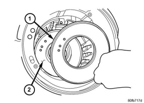
2 2. Install low/reverse piston retainer gasket (2). 3. Install low/reverse piston retainer (1). 2/47
. http://alldatapro.")
3 4. Install low/reverse piston retainer to case screws (3) and torque to 5 Nm (45 in. lbs.). 3/47
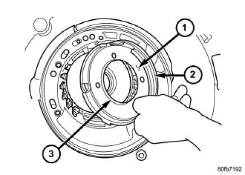
4 NOTE: The Low/Reverse Clutch Piston has bonded seals which are not individually serviceable. Seal replacement requires replacement of the piston assembly. 5. Install low/reverse clutch piston (1). 6. Assemble guide bracket (1) assembly as shown, if necessary. 4/47
. http://alldatapro.")
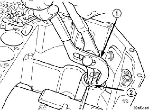
5 CAUTION: When installing, be sure guide bracket and split sleeve touch the rear of the transmission case. 7. Install guide bracket pivot pin (1). 8. Install park sprag pivot retaining screw and torque to 4.5 Nm (40 in. lbs.). 5/47
, 5059A")
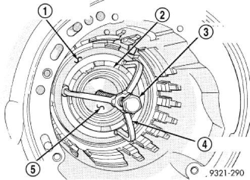
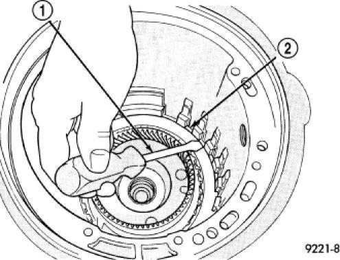
6 9. Install low/reverse piston belleville spring (1) into position. 10. Install and load low/reverse spring with compressor tool 5058A 3 (3), 5059A (4) and disc 6057 (5) as 6/47

7 shown in to facilitate snap ring (2) installation. 11. Install snap ring (1) and remove compressor tool. 7/47
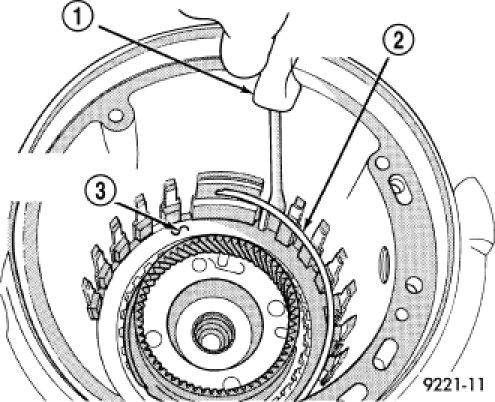
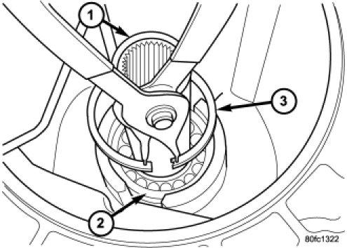
8 12. Install rear carrier (4) front bearing cone. 8/47
 Output shaft bearings Transmission case 13.")
9 Check output bearing preload. Output bearing preload must be checked and/or adjusted if any of the following items have been replaced: Output shaft (rear carrier assembly) Output shaft bearings Transmission case 13. PRELOAD CHECK/SHIM SELECTION: Install rear output shaft bearing cone and Support Plate 6618A (1). 9/47

10 14. Install Support Plate 6618A (1). Lightly tighten retaining screws. Screws should be below the plate surface, but do not snug screws. 15. Turn case over on arbor press so that the plate is resting on the press base. CAUTION: The output shaft will extend through the hole of Support Plate 6618A. Ensure your press table has clearance for the output shaft. 10/47

11 16. Install shim (1) on output shaft (2). Apply small amount of petrolatum onto the shim to hold it in place. Use the original shim as a starting point. If original shim is not available, use the thickest shim available. 11/47
 and Universal Handle C 4171 and Handle Extension C4171 2 (1) to press shaft into rear bearing. http://alldatapro.")
12 17. Install output shaft/rear carrier into rear bearing. The shaft must be pressed into position. Use Disc MD (2) and Universal Handle C 4171 and Handle Extension C (1) to press shaft into rear bearing. 12/47
. 18. Check the turning torque (1) of the output shaft. The shaft should have 1 to 8 in. lbs. of turning torque.")
13 CAUTION: Do not re use old output shaft nut because the removed stake weakens the nut flange. Using Wrenches 6497 and 6498 A, install new output shaft nut. Tighten new output shaft nut to 271 Nm (200 ft. lbs.). 18. Check the turning torque (1) of the output shaft. The shaft should have 1 to 8 in. lbs. of turning torque. If the turning torque is higher than 8 in. lbs., install a thicker shim. If turning torque is less than 1 in. lb., install a thinner shim. Make sure there is no end play. 13/47
 to stake output shaft nut. http://alldatapro.")
14 CAUTION: Failure to stake nut could allow the nut to back off during use. 19. The new nut (3) must be staked after the correct turning torque is obtained. Use Staking Tool 6639 (2) to stake output shaft nut. 14/47
15 20. Verify that the nut has been properly staked to the output shaft. 15/47

16 21. Install low/reverse clutch pack (1, 2). Leave uppermost disc out to facilitate snap ring installation. 16/47

17 22. Install low/reverse reaction plate snap ring (2). 23. Install one low/reverse clutch disc (1). 17/47

18 24. Install low/reverse reaction plate (1) with flat side up. 18/47

19 25. Install a new tapered snap ring (2) (tapered side out). 26. Make sure that the snap ring ends are oriented as shown. 19/47
 places and take average reading.")

20 27. Measure low/reverse clutch pack. Set up dial indicator (1) as shown. Press down clutch pack with finger and zero dial indicator. Record measurement in four (4) places and take average reading. Low/Reverse clutch pack clearance is 0.84 to 1.60 mm (0.033 to inch). 28. Select the proper low/reverse reaction plate to achieve specifications. 20/47
. http://alldatapro.com/alldata/pro~v428906096~c43595~r0~od~n/0/121547197/121549171/124495735/124495737/34853741/34860071/34860072/34860183 21/47")
21 29. Install 2/4 clutch pack (1, 2). NOTE: The 2/4 Clutch Piston has bonded seals which are not individually serviceable. Seal replacement requires replacement of the piston assembly. 30. Install 2/4 clutch belleville spring (1). 21/47
22 31. Verify the proper orientation of the return spring (2) to the 2/4 retainer (3). 22/47
 is centered properly over the 2/4 clutch retainer (4) before http://alldatapro.")
23 32. Install 2/4 clutch retainer (1). NOTE: Verify that Compressor 5058A (1) is centered properly over the 2/4 clutch retainer (4) before 23/47
 as shown. Compress 2/4 clutch just enough to facilitate snap ring installation. 34. Measure 2/4 clutch clearance: Set up dial indicator (1) as shown.")
24 compressing. If necessary, fasten the bar from Compressor 5058A to the bellhousing flange with any combination of locking pliers and bolts to center the tool properly. 33. Set up Compressor 5058 (1) as shown. Compress 2/4 clutch just enough to facilitate snap ring installation. 34. Measure 2/4 clutch clearance: Set up dial indicator (1) as shown. Press down clutch pack with finger and zero dial indicator. Record measurement in four (4) places and take average reading. The 2/4 clutch pack clearance is 0.76 to 2.64 mm (0.030 to inch). If not within specifications, the clutch is not assembled properly or is excessively worn. There is no adjustment for the 2/4 clutch clearance. 24/47

25 35. Install the #7 needle bearing (1) to the rear sun gear (2). The number 7 needle bearing has three antireversal tabs and is common with the number 5 and number 2 position. The orientation should allow the bearing to seat flat against the rear sun gear. A small amount of petrolatum can be used to hold the bearing to the rear sun gear. 36. Install rear sun gear (2) and #7 needle bearing (1). 25/47
. 38.")

26 37. Install front carrier/rear annulus assembly (2) and #6 needle bearing (1). 38. Install front sun gear assembly (1) and #4 thrust washer (2). 26/47

27 39. Determine proper #4 thrust plate thickness. Select the thinnest available #4 thrust plate. 40. Install #4 thrust plate (2) using petrolatum to hold into position. 41. Install input clutch assembly. Ensure the input clutch assembly is completely seated by viewing position through input speed sensor hole. If the speed sensor tone wheel is not centered in the opening, the input clutches assembly is not seated properly. 27/47
28 42. Remove the oil pump o ring (2) and install oil pump and gasket to transmission. Use screw in dowels or Phillips head screwdrivers to align pump to case. Be sure to reinstall O ring on oil pump after selecting the proper No. 4 thrust plate. 43. Measure the input shaft end play with the transmission in the vertical position. This will ensure that the measurement will be accurate. 44. Set up and measure endplay using End Play Set 8266 (1, 2) and Dial Indicator Set C3339A (3) as shown. 45. Measure input shaft end play. Input shaft end play must be to mm (0.005 to inch). For example, if end play reading is inch, select No. 4 Thrust Plate which is to thick. This should provide an input shaft end play reading of inch, which is within specifications. 28/47
 with proper thrust plate. http://alldatapro.")
29 46. Remove oil pump, gasket, and input clutch assembly to gain access to and install proper #4 thrust plate. 47. Install input clutch assembly (1) with proper thrust plate. 29/47

30 48. Install #1 caged needle bearing (1). CAUTION: By pass valve MUST be replaced if transmission failure occurs. 30/47
. http://alldatapro.")
31 49. Replace cooler by pass valve (1) if transmission failure has occurred. NOTE: To align oil pump, gasket, and case during installation, use threaded dowels or Phillips screwdrivers. 50. Install oil pump gasket (2). 31/47

32 51. Install oil pump (2) and torque oil pump to case bolts (1) to 30 Nm (265 in. lbs.). Do not reuse original oil pump bolts. 32/47
33 52. Install low/reverse accumulator (1) as shown. 33/47
34 53. Install low/reverse accumulator plug (2). 54. Install low/reverse accumulator snap ring (1). 34/47
35 55. Install underdrive (2) and overdrive (1) accumulators and springs. 35/47
 valve body to case bolts (1) and torque to 12 Nm (105 in. lbs.). http://alldatapro.")
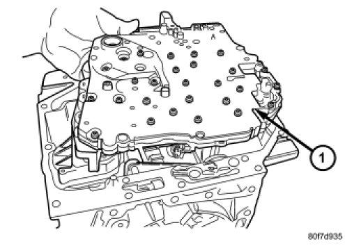
36 CAUTION: Do not handle the valve body by the manual shaft. Damage could result. 56. Install valve body (1) into place as shown. 57. Install seven (7) valve body to case bolts (1) and torque to 12 Nm (105 in. lbs.). 36/47
37 58. Install transmission oil filter (1). Tighten the bolts to 5 Nm (45 in. lbs.). 59. Install transmission oil pan (1) with a bead of Mopar(R) ATF RTV. 37/47
38 NOTE: Before installing the oil pan bolt in the bolt hole located between the torque converter clutch on and U/D clutch pressure tap circuits, it will be necessary to replenish the sealing patch on the bolt using Mopar(R) Lock & Seal Adhesive. 60. Install and torque the oil pan to case bolts to 20 Nm (14.5 ft. lbs.). 38/47
 into the transmission case. Torque the speed sensor bolts to 9 Nm (80 in. lbs.). http://alldatapro.")
39 NOTE: Before installing either speed sensor bolt, it will be necessary to replenish the sealing patch on the bolt using Mopar(R) Lock & Seal Adhesive. 61. Install both speed sensors (1, 2) into the transmission case. Torque the speed sensor bolts to 9 Nm (80 in. lbs.). 39/47
40 62. As a final check of the transmission, measure the input shaft end play. This will indicate when a #4 thrust plate change is required. The #4 thrust plate is located behind the overdrive clutch hub. Attach a dial indicator C 3339A to transmission bell housing with its plunger seated against end of input shaft. Install tool (2), (1) and move input shaft in and out to obtain end play reading. Input shaft end play must be to mm (0.005 to inch). If not within specifications, make the necessary thrust plate adjustment. 63. On 4X2 transmissions, perform the following, if necessary: a. Install the extension shaft bearing (2) onto the extension shaft. b. 40/47
41 Install the extension shaft bearing retaining ring (3) onto the extension shaft (1). c. Install the extension shaft (2) and bearing assembly (3) into the extension housing (1). 41/47
42 d. Install the extension shaft bearing snap ring (3) into the extension housing. e. 42/47
43 Verify that the extension shaft snap ring (3) is fully engaged in the snap ring groove. 43/47
44 64. Inspect the lube tube grommet (2) for damage. If the grommet lip is damaged, it will need to be replaced. 44/47
 onto the transmission case, 4X4 vehicles only. http://alldatapro.")
45 65. Install the 4X4 stub shaft onto the transmission output shaft. 66. Place a bead of Mopar(R) ATF RTV on the rear surface of the transmission case for the adapter/extension housing. 67. Install the adapter housing (2) onto the transmission case, 4X4 vehicles only. 45/47
46 68. Install the extension housing (2) onto the transmission case, 4X2 vehicles only. NOTE: Before installing the lowermost four adapter/extension housing bolts, it will be necessary to replenish the sealing patch on the bolts using Mopar(R) Lock & Seal Adhesive. 46/47
47 69. Install the bolts that hold the adapter or extension housing onto the transmission case. Be sure to install any stud bolts to their original locations. Tighten the bolts to 54 Nm (40 ft.lbs.). 47/47
2007 Dodge Nitro R/T
 ASSEMBLY AUTOMATIC TRANSMISSION - 42RLE NOTE: If the transmission assembly is being reconditioned (clutch/seal replacement) or replaced, it is necessary to perform the TCM QUICK LEARN Procedure using the
2007 Jeep Truck Liberty 4WD V6 3.7L VIN K
 2007 Jeep Truck Liberty 4WD V6 3.7L VIN K Vehicle» Transmission and Drivetrain» Automatic Transmission/Transaxle» Service and Repair» Overhaul» Disassembly DISASSEMBLY NOTE: If the transmission is being
AUTOMATIC TRANSMISSION - 42RLE
 TJ AUTOMATIC TRANSMISSION - 42RLE 21-37 AUTOMATIC TRANSMISSION - 42RLE TABLE OF CONTENTS page AUTOMATIC TRANSMISSION - 42RLE DESCRIPTION...38 OPERATION...40 DIAGNOSIS AND TESTING DIAGNOSIS AND TESTING
NOTE: Clean and inspect all components. Replace any components which show evidence of excessive wear or scoring.
 ASSEMBLY (AUTOMATIC 545RFE)... ASSEMBLY NOTE: Apply trans jell or petroleum jelly to all slide portions, rolling contacts surfaces, thrust surfaces etc. to prevent burnout during initial operation. Lubricate
NOTE: Clean and inspect all components. Replace any components which show evidence of excessive wear or scoring.
 21 - Transmission and Transfer Case/Automatic - 68RFE/Assembly ASSEMBLY Labor Operations: Click to display a list of Labor Operations associated with this procedure Special Tools: Click to display a list
DISASSEMBLY TRANSAXLE DISASSEMBLY AND ASSEMBLY. Part 1 Of 3
 2004 Mitsubishi Truck Endeavor V6-3.8L SOHC Vehicle > Transmission and Drivetrain > Automatic Transmission/Transaxle > Service and Repair > Overhaul > F4A5A > Disassembly and Assembly DISASSEMBLY TRANSAXLE
2000 Jeep Truck Cherokee 4WD L6-4.0L VIN S
 2000 Jeep Truck Cherokee 4WD L6-4.0L VIN S Vehicle» Transmission and Drivetrain» Automatic Transmission/Transaxle» Service and Repair» 30-40LE (AW4) 4 Speed» Overhaul (Transmission)» Disassembly DISASSEMBLY
HIGH PERFORMANCE TRANSMISSION PARTS Instructions. Line Pressure Booster Kit. TCC Control Plunger Valve Kit. Line Pressure Modulator Plunger Valve Kit
 Performance Pack Ford 4R100 Part No. HP-4R100-01 Line Pressure Booster Kit Line-to-Lube Pressure Regulator Valve Line Pressure Booster Kit Valve Sleeve O-Rings (2) TCC Control Plunger Valve Kit Front Lube/Drainback
Assembly. NOTE: Before beginning assembly, perform/inspect the following:
 Page 1 of 31 Home Account Contact ALLDATA Log Out Help DAN GRIMWOOD DAN GRIMWOOD00002 Select Vehicle New TSBs Technician's Reference Component Search: OK 1997 Ford Truck F 150 2WD Pickup V6-4.2L VIN 2
 Page 1 of 22 SECTION 307-01: Automatic Transaxle/Transmission 4R70E/4R75E ASSEMBLY Procedure revision date: 05/29/2009 Transmission Printable View (1554 KB) Special Tool(s) Air Test Plate, Transmission
DRIVE AXLE - 4WD MODELS WITH INTEGRAL HOUSING
 DRIVE AXLE - 4WD MODELS WITH INTEGRAL HOUSING 1988 Toyota Celica DRIVE AXLES Toyota Integral Housing Celica (Rear) DESCRIPTION housing. Drive axle assembly is hypoid type with integral carrier AXLE RATIO
2005 Toyota RAV AUTOMATIC TRANSMISSIONS U240E & U241E Overhaul
 2001-05 AUTOMATIC TRANSMISSIONS U240E & U241E Overhaul APPLICATION CAUTION: Flush oil cooler and oil cooler lines prior to transaxle installation. Oil cooling system contamination may cause premature transaxle
2003 E-Series Workshop Manual
 Page 1 of 20 SECTION 307-01B: Automatic Transmission 4R70W 2003 E-Series Workshop Manual ASSEMBLY Procedure revision date: 04/27/2006 Transmission Printable View (1828 KB) Special Tool(s) Dial Indicator
AUTOMATIC TRANSMISSIONS Mitsubishi F3A20 Series TRANSMISSION APPLICATION TABLE
 Article Text ARTICLE BEGINNING AUTOMATIC TRANSMISSIONS Mitsubishi F3A20 Series APPLICATION TRANSMISSION APPLICATION TABLE Vehicle Application Transmission Model Colt 3-Speed (1990-94)... F3A21 Colt Vista
MANUAL TRANSAXLE Return to Main Table of Contents
 MANUAL TRANSAXLE Return to Main Table of Contents GENERAL... 2 MANUAL TRANSAXLE CONTROL... 12 SHIFT LEVER ASSEMBLY... 14 MANUAL TRANSAXLE... 15 MANUAL TRANSAXLE ASSEMBLY... 17 FIFTH SPEED SYNCHRONIZER
Dismantling and assembling automatic transmission (A5S560Z) (transmission removed)
 (transmission removed)") 24 00 585 Dismantling and assembling automatic transmission (A5S560Z) (transmission removed) Secure transmission to assembly frame with special tool 24 0 180. Drain off transmission oil. Screw special
24 00 585 Dismantling and assembling automatic transmission (A5S560Z) (transmission removed) Secure transmission to assembly frame with special tool 24 0 180. Drain off transmission oil. Screw special
SECTION Automatic Transaxle/Transmission 6R80
 307-01-i Automatic Transaxle/Transmission 6R80 307-01-i SECTION 307-01 Automatic Transaxle/Transmission 6R80 CONTENTS PAGE Transmission... 307-01-2 307-01-2 Automatic Transaxle/Transmission 6R80 307-01-2
ASSEMBLY. Transmission Automatic Transmission 5R44E and 5R55E. Special Tool(s)
") 307-01-1 Automatic Transmission 5R44E and 5R55E 307-01-1 ASSEMBLY Transmission Special Tool(s) Holding Fixture, Transmission 307-262 (T93T-77002-AH) Special Tool(s) Installer, Transmission Extension Housing
307-01-1 Automatic Transmission 5R44E and 5R55E 307-01-1 ASSEMBLY Transmission Special Tool(s) Holding Fixture, Transmission 307-262 (T93T-77002-AH) Special Tool(s) Installer, Transmission Extension Housing
DRIVE AXLE Volvo 960 DESCRIPTION & OPERATION AXLE IDENTIFICATION DRIVE AXLES Volvo Differentials & Axle Shafts
 DRIVE AXLE 1994 Volvo 960 1994 DRIVE AXLES Volvo Differentials & Axle Shafts 960 DESCRIPTION & OPERATION All 960 station wagon models use type 1041 rear axle assembly. All 960 4-door models use type 1045
ASSEMBLY. Transmission Automatic Transaxle/Transmission. Special Tool(s) Alignment Set, Fluid Pump 307-S039 (T74P X) Special Tool(s)
 Alignment Set, Fluid Pump 307-S039 (T74P X) Special Tool(s)") 307-01-1 Automatic Transaxle/Transmission 307-01-1 ASSEMBLY Transmission Special Tool(s) Adjustment Set, Transmission Band 307-S022 (T71P-77370-A) Special Tool(s) Alignment Set, Fluid Pump 307-S039 (T74P-77103-X)
307-01-1 Automatic Transaxle/Transmission 307-01-1 ASSEMBLY Transmission Special Tool(s) Adjustment Set, Transmission Band 307-S022 (T71P-77370-A) Special Tool(s) Alignment Set, Fluid Pump 307-S039 (T74P-77103-X)
DISASSEMBLY AND ASSEMBLY
 307-01-1 Automatic Transaxle/Transmission 307-01-1 DISASSEMBLY AND ASSEMBLY Transaxle Special Tool(s) Dial Indicator Gauge With Holding Fixture 100-002 (TOOL-4201-C) Special Tool(s) Test Plate Screw Set,
23. Planetary Gear and Low Clutch S510212
 Automatic Transmission 23. Planetary Gear and Low Clutch S510212 A: REMOVAL S510212A18 1) Extract the torque converter clutch assembly. 2) Remove
1984 Dodge W250 PICKUP
 1984 Dodge W250 PICKUP Submodel: Engine Type: V8 Liters: 5.2 Fuel Delivery: CARB Fuel: GAS Dana 44 MODELS THROUGH 1984 2. Raise and safely support the vehicle, then remove the wheel hub and bearings as
SECTION Automatic Transaxle/Transmission 6R80
 307-01-i Automatic Transaxle/Transmission 6R80 307-01-i SECTION 307-01 Automatic Transaxle/Transmission 6R80 CONTENTS PAGE Forward Clutch Assembly... 307-01-2 307-01-2 Automatic Transaxle/Transmission
DRIVE AXLE Nissan 240SX DESCRIPTION & OPERATION AXLE RATIO & IDENTIFICATION AXLE SHAFT & BEARING R & I DRIVE SHAFT R & I
 DRIVE AXLE 1990 Nissan 240SX 1990 DRIVE AXLES Rear Axle - R200 240SX, 300ZX DESCRIPTION & OPERATION The axle assembly is a hypoid type gear with integral carrier housing. The pinion bearing preload adjustment
DF 15. DIFFERENTIAL 1GR-FE FRONT DIFFERENTIAL CARRIER ASSEMBLY (for 4WD) REMOVAL
 REMOVAL") DIFFERENTIAL 1GR-FE FRONT DIFFERENTIAL CARRIER ASSEMBLY (for 4WD) 15 REMOVAL 1. REMOVE FRONT WHEELS 2. REMOVE REAR ENGINE UNDER COVER ASSEMBLY (a) Remove the 6 bolts and engine under cover assembly. 3.
DIFFERENTIAL 1GR-FE FRONT DIFFERENTIAL CARRIER ASSEMBLY (for 4WD) 15 REMOVAL 1. REMOVE FRONT WHEELS 2. REMOVE REAR ENGINE UNDER COVER ASSEMBLY (a) Remove the 6 bolts and engine under cover assembly. 3.
1 of 25 9/12/2013 9:07 PM
 1 of 25 9/12/2013 9:07 PM 46RE Automatic Transmission DISASSEMBLY 1. Clean exterior of transmission with suitable solvent or pressure washer. 2. Place transmission in vertical position. 3. Measure the
Transaxle. 1. Mount the transaxle to Bench Mounted Holding Fixture T57L-500-B.
 «1997 Aspire Table of Contents» «Group 07: TRANSAXLE» «Section 07-01: Transaxle, Automatic» «DISASSEMBLY» Transaxle CAUTION: To prevent dirt from entering the transaxle, it should be disassembled and kept
Transmission Overhaul Procedures-Bench Service
 How to Install the Auxiliary Countershaft Assembly Special Instructions To make auxiliary section assembly easier, you can make an auxiliary section fixture out of a 2" x 12" piece of wood. 3' 1' 3" 4.56"
DRIVE AXLE - INTEGRAL HOUSING
 DRIVE AXLE - INTEGRAL HOUSING 1993 Toyota Celica 1993 DRIVE AXLES Toyota Differentials & Axle Shafts - Integral Housing Toyota; Celica All-Trac DESCRIPTION Drive axle assembly is a hypoid type with integral
ASSEMBLY PROCEDURE. Transmission
 67 ASSEMBLY PROCEDURE Transmission Tools Required 0555-336256 Transmission Bench Cradle 0555-336258 Cross Shaft Pin Remover/Installer (Detent Lever) 0555-336262 Cross Shaft Seal Installer 0555-336263 Cross
MANUAL TRANSMISSIONS Mitsubishi F4M20, F5M20, F5M30 & KM200 Series TRANSMISSION APPLICATION
 Article Text ARTICLE BEGINNING MANUAL TRANSMISSIONS Mitsubishi F4M20, F5M20, F5M30 & KM200 Series APPLICATION TRANSMISSION APPLICATION Vehicle Application Transmission Model Chrysler Motors (2WD) 4-Speed
AUTOMATIC TRANSAXLE AUTOMATIC TRANSAXLE SYSTEM... COMPONENT PARTS...
 SYSTEM....... COMPONENT PARTS.................... OIL PUMP.............................. DIRECT CLUTCH........................ FORWARD CLUTCH..................... SECOND BRAKE........................ UNDERDRIVE
ASSEMBLY PROCEDURE AUTOMATIC TRANSMISSION 5A-173. Transmission
 AUTOMATIC TRANSMISSION 5A-173 ASSEMBLY PROCEDURE Transmission Tools Required 0555-336256 Transmission Bench Cradle 0555-336258 Cross Shaft Pin Remover/Installer (Detent Lever) 0555-336262 Cross Shaft Seal
ALLDATA Online Mitsubishi Eclipse GS L4-2350cc 2.4L SOHC MFI - Input Shaft. Input Shaft
 Page 1 of 16 Home Account Contact ALLDATA Log Out Help BEST FORD BEST FORD00001 Select Vehicle New TSBs Technician's Reference Component Search: OK 2002 Mitsubishi Eclipse GS L4-2350cc 2.4L SOHC MFI Conversion
PL TRANSAXLE 21-1 TRANSAXLE TABLE OF CONTENTS NV T350 (A-578) MANUAL TRANSAXLE TH AUTOMATIC TRANSAXLE NV T350 (A-578) MANUAL TRANSAXLE
 MANUAL TRANSAXLE TH AUTOMATIC TRANSAXLE NV T350 (A-578) MANUAL TRANSAXLE") PL TRANSAXLE 21-1 TRANSAXLE TABLE OF CONTENTS page page NV T350 (A-578) MANUAL TRANSAXLE... 1 31TH AUTOMATIC TRANSAXLE... 54 NV T350 (A-578) MANUAL TRANSAXLE TABLE OF CONTENTS page GENERAL INFORMATION
PL TRANSAXLE 21-1 TRANSAXLE TABLE OF CONTENTS page page NV T350 (A-578) MANUAL TRANSAXLE... 1 31TH AUTOMATIC TRANSAXLE... 54 NV T350 (A-578) MANUAL TRANSAXLE TABLE OF CONTENTS page GENERAL INFORMATION
ABBREVIATIONS USED IN THIS MANUAL
 IN6 INTRODUCTION Abbreviations Used in This Manual ABBREVIATIONS USED IN THIS MANUAL A/T ATM Automatic Transmission ATF Automatic Transmission Fluid B 0 Overdrive Brake B 1 Second Coast Brake B 2 Second
1994 Mitsubishi Eclipse GS
 APPLICATIONS CHRYSLER MOTORS MANUAL TRANS OVERHAUL - MITSUBISHI W5M & W6M SERIES MANUAL TRANSMISSIONS Mitsubishi W5M31, TRANSMISSION APPLICATIONS (CHRYSLER MOTORS) Vehicle Application Transmission Model
2013 NATEF Task Area A-2 Automatic Transmission7-2013
 2013 NATEF Task Area A-2 Automatic Transmission7-2013 A. General Transmission & Transaxle Diagnosis B. Transmission & Transaxle Maintenance & Adjustment C. In-Vehicle Transmission & Transaxle Repair D.
2012 NATEF Task Area A 2 Automatic Transmission
 2012 NATEF Task Area A 2 Automatic Transmission A. General Transmission & Transaxle Diagnosis B. Transmission & Transaxle Maintenance & Adjustment C. In Vehicle Transmission & Transaxle Repair D. Off Vehicle
GENERAL SPECIFICATIONS
 AUTOMATIC TRANSMISSION - DESCRIPTION AT-3 GENERAL SPECIFICATIONS AUTOMATIC TRANSMISSION -COMPONENT PARTS REMOVAL COMPONENT PARTS REMOVAL COMPONENTS AT-13 Oil Cooler Union Throttle Cable O-Ring A/T Fluid
Geo Prizm ( LSi) Toyota Celica 1.8L (1994)
 Toyota Celica 1.8L (1994)") Page 1 of 140 ARTICLE BEGINNING APPLICATION TRANSMISSION APPLICATIONS Application Geo Prizm (1993-94 LSi) Toyota Celica 1.6L (1993) Celica 1.8L (1994) Celica 2.2L (1993) Corolla 1.8L MR2 Paseo Transaxle
Page 1 of 140 ARTICLE BEGINNING APPLICATION TRANSMISSION APPLICATIONS Application Geo Prizm (1993-94 LSi) Toyota Celica 1.6L (1993) Celica 1.8L (1994) Celica 2.2L (1993) Corolla 1.8L MR2 Paseo Transaxle
2002 F-Super Duty /Excursion Workshop Manual
 Page 1 of 25 SECTION 307-01: Automatic Transaxle/Transmission 2002 F-Super Duty 250-550/Excursion Workshop Manual ASSEMBLY Procedure revision date: 05/23/2001 Transmission Special Tool(s) Remover, O-Ring
REPAIR MANUAL 5 HP - 30 ZF GETRIEBE GMBH SAARBRÜCKEN
 REPAIR MANUAL 5 HP - 30 ZF GETRIEBE GMBH SAARBRÜCKEN Impressum: Verantwortlich für den Inhalt Abteilung MKTD, ZF Getriebe GmbH, Saarbrücken Druck: HAGER PAPPRINT GmbH, Gedruckt in der BRD Published by
Jatco 5 Speed ATRA. All Rights Reserved. Printed in U.S.A.
 1 2 3 Table Of Contents Transmission Diassembly... 4 Front Pump... 16 Reverse/High Clutch Drum... 18 Direct Clutch Drum... 22 Low Clutch Drum... 26 Planetary Gearsets... 29 Transfer Gear/Reduction Gear...
SECTION 5B MANUAL TRANSMISSION TABLE OF CONTENTS
 SECTION 5B MANUAL TRANSMISSION TABLE OF CONTENTS General Description and Operation... 5B-2 Shift Lever... 5B-2 Transmission Assembly... 5B-2 Specifications... 5B-3 Diagnostic Information and Procedures...
Section 1.24 Gear Train and Engine Timing
 Page 1 of 20 Section 1.24 Gear Train and Engine Timing The gear train is completely enclosed between the gear case and gear case cover and is located at the front of the engine. The gear train consists
SR 55 POWER STEERING GEAR. POWER STEERING GEAR REMOVAL AND INSTALLATION Remove and install the parts, as shown.
 STEERING SR55 GEAR GEAR REMOVAL AND INSTALLATION Remove and install the parts, as shown. SR56 STEERING MAIN POINT OF REMOVAL AND INSTALLATION 1. REMOVE OIL RESERVOIR 2. REMOVE AIR CLEANER ASSEMBLY 3. DISCONNECT
TRANSMISSION PARTS Instructions
 TRANSMISSION PARTS Instructions Sure Cure Kit Part No. SC-4T65E GM 4T65-E Valve Body Parts Boost Valve Kit 84754-30K Patent No. 6,832,632 TCC Apply Valve Kit 84754-43K Patent No. 7,100,753 TCC Regulated
Technical Service Bulletin
 Page 1 of 41 MITSUBISHI MOTORS Technical Service Bulletin SUBJECT No: NOISE FROM CVT AT ALL ENGINE SPEEDS DATE: February, 2015 MODEL: See below CIRCULATE TO: I[ ]GENERAL MANAGER I [ X l PARTS MANAGER I
GM 4L80-E, 4L85-E SURE CURE KIT
 GM 4L80-E, 4L85-E SURE CURE KIT PART NUMBER SC-4L80E INSTALLATION GUIDE Parts are labeled here in order of installation. See page 2 for details on Sure Cure kit contents. See Sure Cure instruction booklet
Locking Differential Adjustment (8.6 Inch Axle)
") Page 1 of 9 2003 Chevrolet Chevy K Silverado - 4WD Sierra, Silverado (VIN C/K) Service Manual Driveline/Axle Rear Drive Axle - Locking/Limited Slip Rear Axle Repair Instructions Document ID: 890757 Locking
Page 1 of 9 2003 Chevrolet Chevy K Silverado - 4WD Sierra, Silverado (VIN C/K) Service Manual Driveline/Axle Rear Drive Axle - Locking/Limited Slip Rear Axle Repair Instructions Document ID: 890757 Locking
GM 4L80-E, 4L85-E SURE CURE KIT
 GM 4L80-E, 4L85-E SURE CURE KIT PART NUMBER SC-4L80E INSTRUCTION BOOKLET Parts are labeled here in order of installation. See page 2 for details on Sure Cure kit contents. See Sure Cure instruction booklet
Geareducer. Repair Manual. Series 27A Series 27T Series 27.1 RM-27D. Manual A
 Geareducer Repair Manual Series 27A Series 27T Series 27.1 RM-27D Manual 92-1412A General Geareducers can be repaired in the field; however, major repairs require the use of a fully equipped machine shop.
SUSPENSION - REAR Toyota Celica DESCRIPTION ADJUSTMENTS & INSPECTION WHEEL ALIGNMENT SPECIFICATIONS & PROCEDURES WHEEL BEARING
 SUSPENSION - REAR 1988 Toyota Celica REAR SUSPENSION Toyota IRS DESCRIPTION The Toyota Independent Rear Suspension (IRS) system utilizes MacPherson struts, which fasten to axle carrier and wheel housing.
InstalL Instructions. trail-creeper 4.70 transfer case gear kit ( KIT and KIT) kit contents
 kit contents") InstalL Instructions trail-creeper 4.70 transfer case gear kit (105000-1-KIT and 105001-1-KIT) kit contents 5356 PINE AVE FRESNO, CA 93727 USA TOLL FREE: 877.4X4.TOYS WORLDWIDE: 559.252.4950 WWW.TRAIL-GEAR.COM
InstalL Instructions trail-creeper 4.70 transfer case gear kit (105000-1-KIT and 105001-1-KIT) kit contents 5356 PINE AVE FRESNO, CA 93727 USA TOLL FREE: 877.4X4.TOYS WORLDWIDE: 559.252.4950 WWW.TRAIL-GEAR.COM
DF 78. HINT: Face the rough side of the thrust washer marked by # to the differential case. INSPECTION
 78 DIFFERENTIAL REAR DIFFERENTIAL CARRIER ASSEMBLY (w/ Differential Lock) Face the rough side of the thrust washer marked by # to the differential case. INSPECTION 1. DIFFERENTIAL SIDE GEAR (w/ LSD Differential)
DISASSEMBLY AND ASSEMBLY
 205-03-1 Front Drive Axle/Differential Ford 8.8-Inch Ring Gear 205-03-1 DISASSEMBLY AND ASSEMBLY Axle Front Drive Special Tool(s) 2-Jaw Puller 205-D072 (D97L-4221-A) Special Tool(s) Carrier Bearing Replacer
2001 Chevrolet Corvette AUTOMATIC TRANSMISSIONS Hydra-Matic 4L60-E - Overhaul
 2001-03 AUTOMATIC TRANSMISSIONS Hydra-Matic 4L60-E - Overhaul APPLICATION CAUTION: Flush oil cooler and oil cooler lines prior to transmission installation. Oil cooling system contamination may cause premature
MANUAL TRANSMISSION SECTIONMT CONTENTS IDX FS5W71C. ASSEMBLY...24 Gear Components...24
 MANUAL TRANSMISSION SECTIONMT GI MA EM LC EC CONTENTS FE FS5W71C PREPARATION...3 Special Service Tools...3 Commercial Service Tools...5 NOISE, VIBRATION AND HARSHNESS (NVH) TROUBLESHOOTING...6 NVH Troubleshooting
1999 F-150/250 Workshop Manual
 Page 1 of 30 SECTION 205-03: Front Drive Axle/Differential Ford 8.8-Inch Ring Gear 1999 F-150/250 Workshop Manual DISASSEMBLY AND ASSEMBLY Procedure revision date: 01/08/2003 Axle Front Drive Special Tool(s)
1989 Jeep Cherokee. STEERING COLUMN' '1989 STEERING Jeep Steering Columns STEERING COLUMN STEERING Jeep Steering Columns
 STEERING COLUMN 1989 STEERING Jeep Steering Columns DESCRIPTION All models use collapsible steering columns. All columns have integral ignition switch and locking device. Optional tilt wheel is available
26 Hume Reserve Court, Nth. Geelong, 3215 Phone: (03) Fax: (03) DUAL RANGE HIGH SPEED INSTALLATION MANUAL. for
 Fax: (03) DUAL RANGE HIGH SPEED INSTALLATION MANUAL. for") 26 Hume Reserve Court, Nth. Geelong, 3215 Phone: (03) 5272 2844 Fax: (03) 5272 2633 GEARLESS CENTRE DIFFERENTIAL FULL-TIME 4X4 TRANSFER CASE CONVERSION DUAL RANGE HIGH SPEED INSTALLATION MANUAL for TOYOTA
26 Hume Reserve Court, Nth. Geelong, 3215 Phone: (03) 5272 2844 Fax: (03) 5272 2633 GEARLESS CENTRE DIFFERENTIAL FULL-TIME 4X4 TRANSFER CASE CONVERSION DUAL RANGE HIGH SPEED INSTALLATION MANUAL for TOYOTA
AUTOMATIC TRANSMISSIONS. General Motors Corp. Hydra-Matic 4L60-E Overhaul
 1997-98 AUTOMATIC TRANSMISSIONS General Motors Corp. Hydra-Matic 4L60-E Overhaul APPLICATION TRANSMISSION APPLICATIONS Application Corvette Transaxle 4L60-E IDENTIFICATION The 4L60-E transmission can be
TRANSFER CASE Mitsubishi Montero APPLICATION DESCRIPTION TESTING 4WD INDICATOR CONTROL UNIT (MONTERO) DETECTION SWITCH
 DETECTION SWITCH") TRANSFER CASE 1993 Mitsubishi Montero 1991-94 TRANSFER CASES Mitsubishi Dodge; Ram-50 Mitsubishi; Pickup, Montero APPLICATION TRANSFER CASE APPLICATIONS TABLE Application (1) Transmission Model Dodge 1991-93
TRANSFER CASE 1993 Mitsubishi Montero 1991-94 TRANSFER CASES Mitsubishi Dodge; Ram-50 Mitsubishi; Pickup, Montero APPLICATION TRANSFER CASE APPLICATIONS TABLE Application (1) Transmission Model Dodge 1991-93
ABBREVIATIONS USED IN THIS
 IN10 INTRODUCTION ABBREVIATIONS USED IN THIS MANUAL ABBREVIATIONS USED IN THIS MANUAL ATF Automatic Transmission Fluid B 0 Overdrive Brake B 2 Second Brake B 3 No. 3 Brake C 0 Overdrive Direct Clutch C
Transmission Overhaul Procedures-Bench Service
 How to Assemble the Lower Reverse Idler Gear Assembly Special Instructions In 1996 Eaton changed the reverse idler system design. In the nut design, the reverse idler bearing was lubricated through a hole
1988 Chevrolet Pickup V SUSPENSION - FRONT (4WD)' 'Front Suspension - "V" Series 1988 SUSPENSION - FRONT (4WD) Front Suspension - "V" Series
' 'Front Suspension - V Series 1988 SUSPENSION - FRONT (4WD) Front Suspension - V Series") 1988 SUSPENSION - FRONT (4WD) Front Suspension - "V" Series DESCRIPTION NOTE: Vehicle serial numbers used in this article has been abbreviated for common reference to Chevrolet and GMC models. Chevrolet
1988 SUSPENSION - FRONT (4WD) Front Suspension - "V" Series DESCRIPTION NOTE: Vehicle serial numbers used in this article has been abbreviated for common reference to Chevrolet and GMC models. Chevrolet
Safety Precautions Certain service procedures may require the vehicle/machine to be disabled (wheels raised off ground, work function disconnected, et
 Service Manual ASM 3 1 -F11 F11-5 through -250 Catalog 9129 8205-02 Februari 2001, GB Safety Precautions Certain service procedures may require the vehicle/machine to be disabled (wheels raised off ground,
COMPONENT LOCATOR > DISASSEMBLED VIEWS
 Page 1 of 26 Service Manual: AUTOMATIC TRANSAXLE - 4T65-E - OVERHAUL COMPONENT LOCATOR > DISASSEMBLED VIEWS Fig 1: Case and Associated Parts Disassembled View (1 of 4) 2004 Buick LeSabre 3.8L Eng Limited
Section X STEERING DATA AND SPECIFICATIONS. 21 degrees 45 minutes -f- or 1 degree (inner wheel when outer wheel is 20 degrees)
") 76 Section X DATA AND SPECIFICATIONS MODELS MC-1 MG-2 MC-3 MY-1 Steering Type Manual Power Worm and Three Tooth Roller None None None Rack and Gear Sector, Recirculating Ball Nut Ratio Manual 20.4... Power
76 Section X DATA AND SPECIFICATIONS MODELS MC-1 MG-2 MC-3 MY-1 Steering Type Manual Power Worm and Three Tooth Roller None None None Rack and Gear Sector, Recirculating Ball Nut Ratio Manual 20.4... Power
REAR AXLE AND SUSPENSION RA 1
 REAR AXLE AND SUSPENSION RA1 RA2 REAR AXLE AND SUSPENSION Troubleshooting TROUBLESHOOTING Problem Possible cause Remedy Page Wanders/pulls Tires worn or improperly inflated Replace tires or inflate to
LIMITED SLIP DIFFERENTIAL INSTALLATION
 Installation of the limited slip gear can be done with axle out of car or with car lifted to gain access from underneath. Refer to repair manual for proper lifting instructions if car is to be lifted.
OVERHAUL. 1. INSPECT 1ST GEAR THRUST CLEARANCE (a) Using a feeler gauge, measure the 1st gear thrust clearance.
 Using a feeler gauge, measure the 1st gear thrust clearance.") 4168 OVERHAUL 410F701 1. INSPECT 1ST GEAR THRUST CLEARANCE (a) Using a feeler gauge, measure the 1st gear thrust clearance. 0.10 to 0.40 mm (0.0039 to 0.0157 in.) 0.40 mm (0.0157 in.) C80538 2. INSPECT
4168 OVERHAUL 410F701 1. INSPECT 1ST GEAR THRUST CLEARANCE (a) Using a feeler gauge, measure the 1st gear thrust clearance. 0.10 to 0.40 mm (0.0039 to 0.0157 in.) 0.40 mm (0.0157 in.) C80538 2. INSPECT
46RE, 46RH, 47RE, 47RH ZIP KIT
 46RE, 46RH, 47RE, 47RH ZIP KIT PART NUMBER 46-47RHE-ZIP QUICK GUIDE Parts are labeled here in order of installation. See other side of sheet for details on Zip Kit contents. installation Diagram 7 1 Separator
DISASSEMBLY. Transmission. All vehicles
 307-01-1 Automatic Transmission 5R44E and 5R55E 307-01-1 DISASSEMBLY Transmission Special Tool(s) Holding Fixture, Transmission 307-262 (T93T-77002-AH) Special Tool(s) Remover, Servo 307-347 (T97T-7D021-A)
15.Main Shaft Assembly
 15.Main Shaft Assembly A: REMOVAL 1) Remove the manual transmission assembly from vehicle. 2) Remove the transfer case with extension case assembly.
SA 82 Front Differential (Disassembly and Assembly of Differential w/ ADD) Disassembly and Assembly of Differential (with A.D.D.)
 Disassembly and Assembly of Differential (with A.D.D.)") SA82 SUSPENSION AND AXLE Disassembly and Assembly of Differential (with A.D.D.) DISASSEMBLY OF DIFFERENTIAL 1. REMOVE ACTUATOR (a) Remove the four bolts. (b) Using a hammer, remove the actuator. SA83 2.
SA82 SUSPENSION AND AXLE Disassembly and Assembly of Differential (with A.D.D.) DISASSEMBLY OF DIFFERENTIAL 1. REMOVE ACTUATOR (a) Remove the four bolts. (b) Using a hammer, remove the actuator. SA83 2.
MANUAL TRANSMISSION SECTIONMT CONTENTS IDX FS5W71C. Case Components...27
 MANUAL TRANSMISSION SECTIONMT GI MA EM LC EC CONTENTS FE FS5W71C PREPARATION...3 Special Service Tools...3 Commercial Service Tools...5 NOISE, VIBRATION AND HARSHNESS (NVH) TROUBLESHOOTING...6 NVH Troubleshooting
BRAKE SYSTEM Toyota Celica DESCRIPTION DRUM BRAKES ADJUSTMENTS BRAKE PEDAL HEIGHT ADJUSTMENTS BRAKE PEDAL FREE PLAY ADJUSTMENTS
 BRAKE SYSTEM 1988 Toyota Celica 1988-89 BRAKES Toyota Celica, Corolla, MR2, Tercel DESCRIPTION The hydraulic brake system uses a tandem master cylinder with a vacuum power assist servo. MR2 and some Celica
DIFFERENTIALS & AXLE SHAFTS
 DIFFERENTIALS & AXLE SHAFTS 2001 Chevrolet Camaro 2000-01 DRIVE AXLES General Motors Differentials & Axle Shafts Chevrolet; Camaro Pontiac; Firebird DESCRIPTION & OPERATION Drive axle is a semi-floating,
CLUTCH CONTENTS SERVICE DIAGNOSIS. (a) Worn or damaged disc assembly. (b) Grease or oil on disc facings. (c) Improperly adjusted cover assembly.
 Worn or damaged disc assembly. (b) Grease or oil on disc facings. (c) Improperly adjusted cover assembly.") CLUTCH CONTENTS -GROUP 6 Page CLUTCH HOUSING ALIGNMENT... 6 CLUTCH PEDAL FREE PLAY 1 CLUTCH RELEASE BEARING 5 CLUTCH RELEASE FORK... 5 CLUTCH SERVICING 2 PILOT BUSHING CRANKSHAFT TO TRANSMISSION DRIVE
CLUTCH CONTENTS -GROUP 6 Page CLUTCH HOUSING ALIGNMENT... 6 CLUTCH PEDAL FREE PLAY 1 CLUTCH RELEASE BEARING 5 CLUTCH RELEASE FORK... 5 CLUTCH SERVICING 2 PILOT BUSHING CRANKSHAFT TO TRANSMISSION DRIVE
Front Hub and Disc (4WD Model)
") 4C 8 DRIVE SHAFT SYSTEM Disassembled View Front Hub and Disc (4WD Model) 411RW001 Legend (1) Bolt (2) Cap (3) Snap Ring and Shim (4) Hub Flange (5) Lock Washer and Lock Screw (6) Hub Nut (7) Outer Bearing
4C 8 DRIVE SHAFT SYSTEM Disassembled View Front Hub and Disc (4WD Model) 411RW001 Legend (1) Bolt (2) Cap (3) Snap Ring and Shim (4) Hub Flange (5) Lock Washer and Lock Screw (6) Hub Nut (7) Outer Bearing
Maintenance Manual MM-0194 Single reduction leading axle carrier for tandem axle series MD61. Revised September 2017
 Maintenance Manual MM-0194 Single reduction leading axle carrier for tandem axle series MD61 Revised September 2017 Service Notes Before You Begin This publication provides installation and maintenance
PROPELLER SHAFT & DIFFERENTIAL CARRIER SECTIONPD CONTENTS
 PROPELLER SHAFT & DIFFERENTIAL CARRIER SECTIONPD CONTENTS PREPARATION...2 PROPELLER SHAFT...5 On-Vehicle Service...6 Removal and Installation...7 Inspection...7 Disassembly...7 Assembly...8 ON-VEHICLE
2001 Dodge RAM 3500 PICKUP
 1 of 76 9/14/2012 7:02 PM 2001 Dodge RAM 3500 PICKUP Submodel: Engine Type: L6 Liters: 5.9 Fuel Delivery: FI Fuel: DIESEL Subarticles MANUAL- NV3500 - DISASSEMBLY MANUAL- NV3500 - DISASSEMBLY MANUAL -
Repair Manual VW 02J gearbox. INA GearBOX
 Repair Manual VW 02J gearbox INA GearBOX Special tools Pipe section, 50 mm: Press fitting of synchronizer body for third/fourth gear. Assembly of support bearing for input and output shaft. Part number:
3.2 DRIVE TORQUE HUB. Roll, Leak and Brake Testing SECTION 3 - CHASSIS & TURNTABLE. 3-2 JLG Lift
 3.2 DRIVE TORQUE HUB Roll, Leak and Brake Testing 10 LUG PATTERN Torque-Hub units should always be roll and leak tested before disassembly and after assembly to make sure that the unit's gears, bearings
SECTION TF CONTENTS TRANSFER IDX
 TRANSFER SECTION TF GI MA EM LC PREPARATION...2 Special Service Tools...2 Commercial Service Tools...3 NOISE, VIBRATION AND HARSHNESS (NVH) TROUBLESHOOTING...4 NVH Troubleshooting Chart...4 Transfer...4
REMOVAL TF REMOVE TRANSFER INDICATOR SWITCH (a) Remove the switches and gaskets. HINT: Indicator switch:
 Remove the switches and gaskets. HINT: Indicator switch:") 20 NO. 1 NO. 2 F043499 REMOVAL 1. DISCONNECT CABLE FROM NEGATIVE BATTERY TERMINAL CAUTION: Wait at least 90 seconds after disconnecting the cable from the negative (-) battery terminal to prevent airbag
20 NO. 1 NO. 2 F043499 REMOVAL 1. DISCONNECT CABLE FROM NEGATIVE BATTERY TERMINAL CAUTION: Wait at least 90 seconds after disconnecting the cable from the negative (-) battery terminal to prevent airbag
kit (17% High Range Reduction, 87% Low Range Reduction)
") InstalL Instructions suzuki jimny electric/push-button transfer Case gears 304088-3-kit (17% High Range Reduction, 87% Low Range Reduction) kit contents INCLUDED NOTE: If your Jimny has an automatic transmission,
InstalL Instructions suzuki jimny electric/push-button transfer Case gears 304088-3-kit (17% High Range Reduction, 87% Low Range Reduction) kit contents INCLUDED NOTE: If your Jimny has an automatic transmission,
MANUAL TRANS OVERHAUL - BORG-WARNER - T56 6-SPEED MANUAL TRANSMISSIONS Borg-Warner T56 (MM6) 6-Speed
 6-Speed") IDENTIFICATION MANUAL TRANS OVERHAUL - BORG-WARNER - T56 6-SPEED 1998 MANUAL TRANSMISSIONS Borg-Warner T56 (MM6) 6-Speed Transmission has 2 identification labels, located on lower left side of case. One
IDENTIFICATION MANUAL TRANS OVERHAUL - BORG-WARNER - T56 6-SPEED 1998 MANUAL TRANSMISSIONS Borg-Warner T56 (MM6) 6-Speed Transmission has 2 identification labels, located on lower left side of case. One
STEPS Install the (A) input shaft with long spliced end first. Install the (B) aligning pin.
 input shaft with long spliced end first. Install the (B) aligning pin.") 1999 Ford Truck Econoline E450 Super Duty V10-6.8L VIN S Vehicle > Transmission and Drivetrain > Automatic Transmission/Transaxle > Service and Repair > Overhaul > 4R100 > Assembly STEPS 51-94 51. Install
1999 Ford Truck Econoline E450 Super Duty V10-6.8L VIN S Vehicle > Transmission and Drivetrain > Automatic Transmission/Transaxle > Service and Repair > Overhaul > 4R100 > Assembly STEPS 51-94 51. Install
REPAIR MANUAL. Version 02/11/01 CD ZF GETRIEBE GMBH SAARBRÜCKEN
 REPAIR MANUAL 6 HP-26 Version CD ZF GETRIEBE GMBH SAARBRÜCKEN subject to alterations Copyright 2002 all rights reserved and published by ZF Getriebe GmbH, Saarbrücken, Department MKTD No part of this manual
Aisin Warner LE 1998-Up Nissan UD Isuzu RNJ Mitsubishi FUSO
 Aisin Warner 450-43LE 1998-Up Nissan UD Isuzu RNJ Mitsubishi FUSO AISIN SEIKI CO., LTD. SERIAL NO. 9A0001 Year: 1999 Month: January Ex. B: February C: March D: April * * L: December Serial Numbers Component
 Page 1 of 75 303-01D Engine - 5.2L 32V Ti-VCT 2016 Mustang Assembly Procedure revision date: 12/15/2016 Special Tool(s) / General Equipment Engine Base Part Number: 6L084 205-142 (T80T-4000-J) Installer,
AUTOMATIC TRANSAXLE F4A33, W4A32, W4A33 CONTENTS
 AUTOMATIC TRANSAXLE F4A33, W4A32, W4A33 CONTENTS ANNULUS GEAR AND TRANSFER DRIVE GEAR SET... 100 CENTER DIFFERENTIAL - 4WD... 115 DIFFERENTIAL... 102 END CLUTCH... 94 EXTENSION HOUSING - 4WD... 130 FRONT
REPAIR INSTRUCTIONS ON-VEHICLE SERVICE TRANSMISSION AUTOMATIC TRANSMISSION 5A-159. Removal and Installation Procedure
 REPAIR INSTRUCTIONS YAD5A080 AUTOMATIC TRANSMISSION 5A-159 ON-VEHICLE SERVICE TRANSMISSION Removal and Installation Procedure 1. Disconnect the negative battery cable. 2. Disconnect the connectors from
Flexplate Conversion Installation Instructions
 Flexplate Conversion Installation Instructions For all Wagner units using Clark 8000 torque converter. Use the following instructions for modifying your ring gear torque converter to a fl explate torque