2007 Jeep Truck Liberty 4WD V6 3.7L VIN K
|
|
|
- Erick Tate
- 5 years ago
- Views:
Transcription

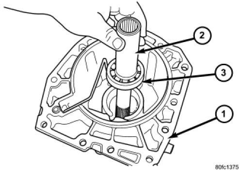
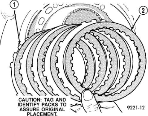
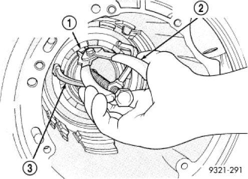
1 2007 Jeep Truck Liberty 4WD V6 3.7L VIN K Vehicle» Transmission and Drivetrain» Automatic Transmission/Transaxle» Service and Repair» Overhaul» Disassembly DISASSEMBLY NOTE: If the transmission is being reconditioned (clutch/seal replacement) or replaced, it is necessary to perform the Quick Learn Procedure using the scan tool. NOTE: Tag all clutch pack assemblies, as they are removed, for reassembly identification. CAUTION: Do not intermix clutch discs or plates as the unit might then fail. Before disassembling transmission, move the shift lever clockwise as far as it will go and then remove the shift lever. 1. Remove the torque converter (1) from the transmission input shaft (3). 1/43
 as shown. 3. Move input shaft in and out to obtain end play reading. End play specifications are 0.127 to 0.635 mm (0.005 to 0.025 inch).")
2 2. Measure input shaft end play using End Play Set 8266 (1, 2). Set up the required items from End Play Set 8266 (1, 2) and a dial indicator C 3339A (3) as shown. 3. Move input shaft in and out to obtain end play reading. End play specifications are to mm (0.005 to inch). Record indicator reading for reference when reassembling the transmission. If end play exceeds the specified range, the #4 thrust plate needs to be inspected and changed if necessary. 2/43
 onto the transmission case. 5. Remove the adapter (2) housing, 4X4 vehicles only, from the transmission case.")
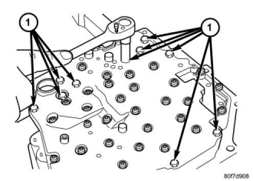
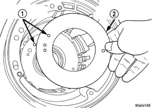
3 NOTE: The four bolts (3) along the bottom of the adapter or extension housing (2) have a sealing patch applied from the factory. Note the locations of these bolts and separate these bolts for reuse. 4. Remove the bolts that hold the adapter or extension housing (2) onto the transmission case. 5. Remove the adapter (2) housing, 4X4 vehicles only, from the transmission case. There are two pry slots located near the bottom corners of the housing for separating the housing from the transmission case. 3/43

4 6. Remove the extension (2) housing, 4X2 vehicles only, from the transmission case. There are two pry slots located near the bottom corners of the housing for separating the housing from the transmission case. 4/43

5 7. Inspect the lube tube grommet (3) for damage. If the grommet lip is damaged, it will need to be replaced. 8. On 4X2 transmissions, perform the following, if necessary: a. 5/43
 from the extension")
6 Remove the extension shaft bearing snap ring (3) from the extension housing. b. Remove the extension shaft and bearing assembly (2) from the extension housing (1). 6/43
7 c. Remove the extension shaft bearing retaining ring (3) from the extension shaft (1). d. 7/43
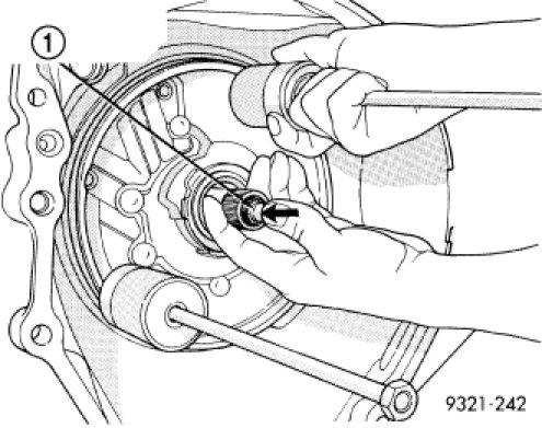
8 Remove the extension shaft bearing (2) from the extension shaft (1). 9. Using a Slide Hammer C 3752 (2), remove the 4X4 stub shaft (1). 8/43
9 10. Remove the 4X4 stub shaft (1) from the transmission output shaft. Inspect the cir clip on the shaft for damage and replace the clip if necessary. 9/43
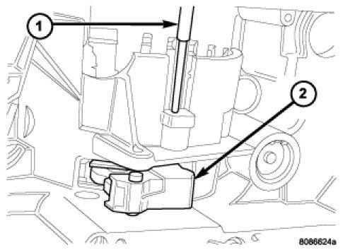
10 NOTE: The speed sensor bolts have a sealing patch applied from the factory. Separate these bolts for reuse. 11. Remove the input speed sensor bolt. NOTE: The speed sensor bolts have a sealing patch applied from the factory. Separate these bolts for reuse. 12. Remove the output speed sensor bolt. 10/43

11 13. Remove the input and output (2) speed sensors. Identify the speed sensors for re installation since they are not interchangeable. 11/43
12 NOTE: One of the oil pan bolts has a sealing patch applied from the factory. Separate this bolt for reuse. 14. Remove the transmission oil pan bolts (2). 15. Remove the transmission oil pan (1). 12/43
13 16. Remove the transmission oil filter screws (2). 17. Remove transmission oil filter (1). 13/43

14 18. Remove the oil filter o ring (2) from the valve body. 14/43
 from transmission. http://alldatapro.")
15 19. Remove valve body to case bolts (1). CAUTION: Do not handle the valve body by the manual shaft. Damage could result. 20. Remove valve body (1) from transmission. 15/43
16 21. Remove underdrive and overdrive accumulators (1, 2). 16/43
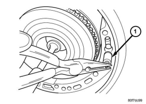
17 22. Remove the low/reverse accumulator snap ring (1). 17/43
18 23. Remove the low/reverse accumulator plug (2). 24. Remove low/reverse accumulator piston (1) using suitable pliers. 18/43

19 25. Remove piston (1) and springs (2). 26. Remove and discard the oil pump to case bolts (1). The oil pump bolts are not to be reused. 19/43
. http://alldatapro.")
20 27. Remove oil pump using Slide Hammers C 3752 (2). 20/43
. http://alldatapro.")
21 28. Remove oil pump while pushing in on input shaft (1). 29. Remove oil pump gasket (2). 21/43
22 CAUTION: By pass valve must be replaced if transmission failure occurs. 30. Remove the cooler by pass valve (1). 31. Remove the #1 caged needle bearing (1). 22/43
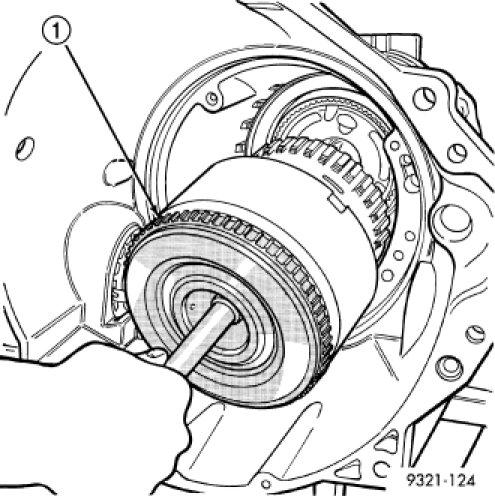
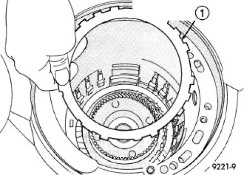
23 32. Remove the input clutch assembly (1). 23/43

24 33. Remove the #4 thrust plate (2). 34. Remove the front sun gear assembly (1) and #4 thrust washer (if still in place). 24/43
. 36. Remove the rear sun gear (2) and #7 needle bearing (1).")
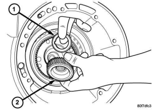
25 35. Remove the front carrier/rear annulus (2) and #6 needle bearing (1). 36. Remove the rear sun gear (2) and #7 needle bearing (1). 25/43

26 NOTE: The number seven needle bearing (1) has three antireversal tabs and is common with the number five and number two position. The orientation should allow the bearing to seat flat against the rear sun gear. A small amount of petrolatum can be used to hold the bearing to the rear sun gear. NOTE: Verify that Compressor 5058A (1) is centered properly over the 2/4 clutch retainer (4) before compressing. If necessary, fasten the Compressor 5058A bar to the bellhousing flange with any combination of locking pliers and bolts to center the tool properly. 26/43
. http://alldatapro.")
27 37. Install and load Compressor 5058A to remove the 2/4 clutch retainer snap ring (3). NOTE: The 2/4 Clutch Piston has bonded seals which are not individually serviceable. Seal replacement requires replacement of the piston assembly. 38. Remove the 2/4 clutch retainer (1). 27/43

28 39. Remove the 2/4 clutch return spring (1). 28/43
. http://alldatapro.")
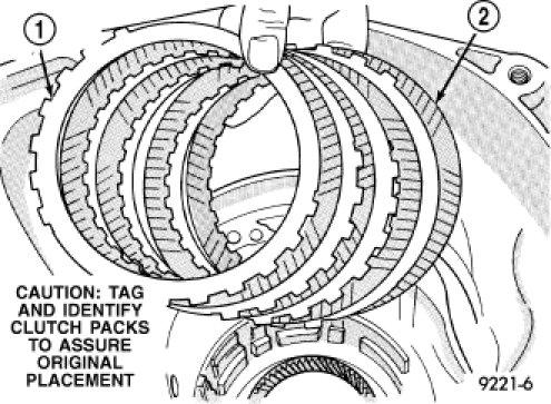
29 40. Remove the 2/4 clutch pack (1, 2). 41. Remove the tapered snap ring (4). 29/43

30 42. Remove the low/reverse reaction plate (1). 43. Remove one (1) low/reverse clutch disc to facilitate snap ring removal. 30/43
. http://alldatapro.")
31 44. Remove the low/reverse reaction plate snap ring (2). 31/43

32 45. Remove the low/reverse clutch pack (1, 2). CAUTION: Failure to grind and open stakes (4) of the output shaft nut will result in thread damage to the shaft during nut removal. WARNING: Wear safety goggles while grinding stake nuts. 32/43

33 46. Using a die grinder or equivalent, grind the stakes in the shoulder of the shaft nut (2) as shown. Do not grind all the way through the nut and into the shaft. There are two stakes on each nut. 33/43
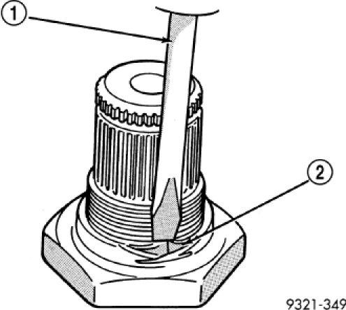
34 47. Using a small chisel (1), carefully open the stakes on nut (2). 34/43


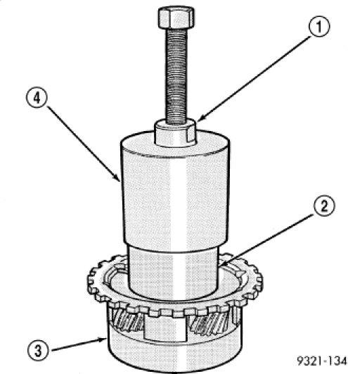
35 48. Use Wrench 6497 (1) and Socket Wrench 6498A (2) to remove the output shaft nut. 49. Remove the output shaft (1) from case (3) using a shop press (2). 35/43
36 50. Use Remover 6596 (2) with a shop press (1) to remove the front output shaft bearing cup. 36/43

37 51. Use Disc 6597 (2) and Universal Handle C 4171 (1) and Handle Extension C to press the rear output shaft bearing cup rearward. 37/43
38 52. Remove the rear carrier front bearing cone (3). 38/43
 as shown. 54.")
39 53. Install and load Compressor 5059A (4), Compressor 5058A (3), and Disc 6057 (5) as shown. 54. Remove the low/reverse belleville spring snap ring (1). 39/43
. http://alldatapro.")
40 55. Remove the low/reverse piston belleville spring (1). 40/43

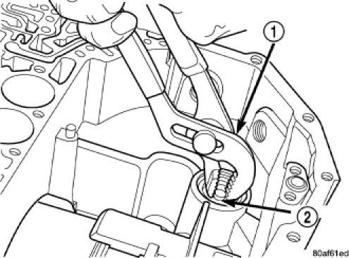
41 56. Remove the park sprag pivot retaining screw. 57. Drive out the anchor shaft using suitable punch (1). 58. Remove the guide bracket pivot pin (1). Inspect all components for wear and replace if necessary. 41/43
. 60. Remove the low/reverse piston retainer screws. http://alldatapro.")
42 NOTE: The Low/Reverse Clutch Piston has bonded seals which are not individually serviceable. Seal replacement requires replacement of the piston assembly. 59. Remove the low/reverse clutch piston (1). 60. Remove the low/reverse piston retainer screws. 42/43
.")
43 61. Remove low/reverse piston retainer (1). 62. Remove the low/reverse piston retainer gasket (2). 43/43
2007 Jeep Truck Liberty 4WD V6 3.7L VIN K
 2007 Jeep Truck Liberty 4WD V6 3.7L VIN K Vehicle» Transmission and Drivetrain» Automatic Transmission/Transaxle» Service and Repair» Overhaul» Assembly ASSEMBLY NOTE: If the transmission assembly is being
2007 Dodge Nitro R/T
 ASSEMBLY AUTOMATIC TRANSMISSION - 42RLE NOTE: If the transmission assembly is being reconditioned (clutch/seal replacement) or replaced, it is necessary to perform the TCM QUICK LEARN Procedure using the
AUTOMATIC TRANSMISSION - 42RLE
 TJ AUTOMATIC TRANSMISSION - 42RLE 21-37 AUTOMATIC TRANSMISSION - 42RLE TABLE OF CONTENTS page AUTOMATIC TRANSMISSION - 42RLE DESCRIPTION...38 OPERATION...40 DIAGNOSIS AND TESTING DIAGNOSIS AND TESTING
DISASSEMBLY TRANSAXLE DISASSEMBLY AND ASSEMBLY. Part 1 Of 3
 2004 Mitsubishi Truck Endeavor V6-3.8L SOHC Vehicle > Transmission and Drivetrain > Automatic Transmission/Transaxle > Service and Repair > Overhaul > F4A5A > Disassembly and Assembly DISASSEMBLY TRANSAXLE
NOTE: Clean and inspect all components. Replace any components which show evidence of excessive wear or scoring.
 ASSEMBLY (AUTOMATIC 545RFE)... ASSEMBLY NOTE: Apply trans jell or petroleum jelly to all slide portions, rolling contacts surfaces, thrust surfaces etc. to prevent burnout during initial operation. Lubricate
Assembly. NOTE: Before beginning assembly, perform/inspect the following:
 Page 1 of 31 Home Account Contact ALLDATA Log Out Help DAN GRIMWOOD DAN GRIMWOOD00002 Select Vehicle New TSBs Technician's Reference Component Search: OK 1997 Ford Truck F 150 2WD Pickup V6-4.2L VIN 2
2000 Jeep Truck Cherokee 4WD L6-4.0L VIN S
 2000 Jeep Truck Cherokee 4WD L6-4.0L VIN S Vehicle» Transmission and Drivetrain» Automatic Transmission/Transaxle» Service and Repair» 30-40LE (AW4) 4 Speed» Overhaul (Transmission)» Disassembly DISASSEMBLY
NOTE: Clean and inspect all components. Replace any components which show evidence of excessive wear or scoring.
 21 - Transmission and Transfer Case/Automatic - 68RFE/Assembly ASSEMBLY Labor Operations: Click to display a list of Labor Operations associated with this procedure Special Tools: Click to display a list
2005 Toyota RAV AUTOMATIC TRANSMISSIONS U240E & U241E Overhaul
 2001-05 AUTOMATIC TRANSMISSIONS U240E & U241E Overhaul APPLICATION CAUTION: Flush oil cooler and oil cooler lines prior to transaxle installation. Oil cooling system contamination may cause premature transaxle
 Page 1 of 22 SECTION 307-01: Automatic Transaxle/Transmission 4R70E/4R75E ASSEMBLY Procedure revision date: 05/29/2009 Transmission Printable View (1554 KB) Special Tool(s) Air Test Plate, Transmission
SECTION Automatic Transaxle/Transmission 6R80
 307-01-i Automatic Transaxle/Transmission 6R80 307-01-i SECTION 307-01 Automatic Transaxle/Transmission 6R80 CONTENTS PAGE Transmission... 307-01-2 307-01-2 Automatic Transaxle/Transmission 6R80 307-01-2
1 of 25 9/12/2013 9:07 PM
 1 of 25 9/12/2013 9:07 PM 46RE Automatic Transmission DISASSEMBLY 1. Clean exterior of transmission with suitable solvent or pressure washer. 2. Place transmission in vertical position. 3. Measure the
DISASSEMBLY. Transmission. All vehicles
 307-01-1 Automatic Transmission 5R44E and 5R55E 307-01-1 DISASSEMBLY Transmission Special Tool(s) Holding Fixture, Transmission 307-262 (T93T-77002-AH) Special Tool(s) Remover, Servo 307-347 (T97T-7D021-A)
2003 E-Series Workshop Manual
 Page 1 of 20 SECTION 307-01B: Automatic Transmission 4R70W 2003 E-Series Workshop Manual ASSEMBLY Procedure revision date: 04/27/2006 Transmission Printable View (1828 KB) Special Tool(s) Dial Indicator
Transaxle. 1. Mount the transaxle to Bench Mounted Holding Fixture T57L-500-B.
 «1997 Aspire Table of Contents» «Group 07: TRANSAXLE» «Section 07-01: Transaxle, Automatic» «DISASSEMBLY» Transaxle CAUTION: To prevent dirt from entering the transaxle, it should be disassembled and kept
DISASSEMBLY. Transmission. 2. Remove the 4 clutch housing bolts. Separate the clutch housing from the transmission.
 308-03A-1 DISASSEMBLY Transmission 308-03A-1 Special Tool(s) Puller, Bearing 205-D064 (D84L-1123-A) or equivalent Remover/Installer, Front Wheel Hub 204-069 (T81P-1104-C) 2. Remove the 4 clutch housing
REMOVAL TF REMOVE TRANSFER INDICATOR SWITCH (a) Remove the switches and gaskets. HINT: Indicator switch:
 Remove the switches and gaskets. HINT: Indicator switch:") 20 NO. 1 NO. 2 F043499 REMOVAL 1. DISCONNECT CABLE FROM NEGATIVE BATTERY TERMINAL CAUTION: Wait at least 90 seconds after disconnecting the cable from the negative (-) battery terminal to prevent airbag
20 NO. 1 NO. 2 F043499 REMOVAL 1. DISCONNECT CABLE FROM NEGATIVE BATTERY TERMINAL CAUTION: Wait at least 90 seconds after disconnecting the cable from the negative (-) battery terminal to prevent airbag
ASSEMBLY. Transmission Automatic Transaxle/Transmission. Special Tool(s) Alignment Set, Fluid Pump 307-S039 (T74P X) Special Tool(s)
 Alignment Set, Fluid Pump 307-S039 (T74P X) Special Tool(s)") 307-01-1 Automatic Transaxle/Transmission 307-01-1 ASSEMBLY Transmission Special Tool(s) Adjustment Set, Transmission Band 307-S022 (T71P-77370-A) Special Tool(s) Alignment Set, Fluid Pump 307-S039 (T74P-77103-X)
307-01-1 Automatic Transaxle/Transmission 307-01-1 ASSEMBLY Transmission Special Tool(s) Adjustment Set, Transmission Band 307-S022 (T71P-77370-A) Special Tool(s) Alignment Set, Fluid Pump 307-S039 (T74P-77103-X)
ASSEMBLY. Transmission Automatic Transmission 5R44E and 5R55E. Special Tool(s)
") 307-01-1 Automatic Transmission 5R44E and 5R55E 307-01-1 ASSEMBLY Transmission Special Tool(s) Holding Fixture, Transmission 307-262 (T93T-77002-AH) Special Tool(s) Installer, Transmission Extension Housing
307-01-1 Automatic Transmission 5R44E and 5R55E 307-01-1 ASSEMBLY Transmission Special Tool(s) Holding Fixture, Transmission 307-262 (T93T-77002-AH) Special Tool(s) Installer, Transmission Extension Housing
BRAKE SYSTEM Toyota Celica DESCRIPTION DRUM BRAKES ADJUSTMENTS BRAKE PEDAL HEIGHT ADJUSTMENTS BRAKE PEDAL FREE PLAY ADJUSTMENTS
 BRAKE SYSTEM 1988 Toyota Celica 1988-89 BRAKES Toyota Celica, Corolla, MR2, Tercel DESCRIPTION The hydraulic brake system uses a tandem master cylinder with a vacuum power assist servo. MR2 and some Celica
1. General Description
 1. General Description A: SPECIFICATION 1. MANUAL TRANSMISSION AND FRONT DIFFERENTIAL Type Transmission gear ratio Front reduction gear Rear reduction gear Front differential Center differential Final
GENERAL SPECIFICATIONS
 AUTOMATIC TRANSMISSION - DESCRIPTION AT-3 GENERAL SPECIFICATIONS AUTOMATIC TRANSMISSION -COMPONENT PARTS REMOVAL COMPONENT PARTS REMOVAL COMPONENTS AT-13 Oil Cooler Union Throttle Cable O-Ring A/T Fluid
AUTOMATIC TRANSMISSIONS Mitsubishi F3A20 Series TRANSMISSION APPLICATION TABLE
 Article Text ARTICLE BEGINNING AUTOMATIC TRANSMISSIONS Mitsubishi F3A20 Series APPLICATION TRANSMISSION APPLICATION TABLE Vehicle Application Transmission Model Colt 3-Speed (1990-94)... F3A21 Colt Vista
23. Planetary Gear and Low Clutch S510212
 Automatic Transmission 23. Planetary Gear and Low Clutch S510212 A: REMOVAL S510212A18 1) Extract the torque converter clutch assembly. 2) Remove
Installation Instructions COMPETITION/PLUS SHIFTER Ford Mustang MT82 6-Speed Manual Transmission Catalog#
 Installation Instructions COMPETITION/PLUS SHIFTER 2015-2017 Ford Mustang MT82 6-Speed Manual Transmission Catalog# 3916037 Rev. 00 WORK SAFELY! For maximum safety, perform this installation on a clean,
HIGH PERFORMANCE TRANSMISSION PARTS Instructions. Line Pressure Booster Kit. TCC Control Plunger Valve Kit. Line Pressure Modulator Plunger Valve Kit
 Performance Pack Ford 4R100 Part No. HP-4R100-01 Line Pressure Booster Kit Line-to-Lube Pressure Regulator Valve Line Pressure Booster Kit Valve Sleeve O-Rings (2) TCC Control Plunger Valve Kit Front Lube/Drainback
Jatco 5 Speed ATRA. All Rights Reserved. Printed in U.S.A.
 1 2 3 Table Of Contents Transmission Diassembly... 4 Front Pump... 16 Reverse/High Clutch Drum... 18 Direct Clutch Drum... 22 Low Clutch Drum... 26 Planetary Gearsets... 29 Transfer Gear/Reduction Gear...
AUTOMATIC TRANSAXLE AUTOMATIC TRANSAXLE SYSTEM... COMPONENT PARTS...
 SYSTEM....... COMPONENT PARTS.................... OIL PUMP.............................. DIRECT CLUTCH........................ FORWARD CLUTCH..................... SECOND BRAKE........................ UNDERDRIVE
HIGH PERFORMANCE TRANSMISSION PARTS Instructions. Line Pressure Booster Kit. TCC Control Plunger Valve Kit. Line Pressure Modulator Plunger Valve Kit
 Performance Pack Ford 4R100 Part No. HP-4R100-01 Line Pressure Booster Kit Line-to-Lube Pressure Regulator Valve Line Pressure Booster Kit Valve Sleeve O-Rings (2) TCC Control Plunger Valve Kit Front Lube/Drainback
ABBREVIATIONS USED IN THIS MANUAL
 IN6 INTRODUCTION Abbreviations Used in This Manual ABBREVIATIONS USED IN THIS MANUAL A/T ATM Automatic Transmission ATF Automatic Transmission Fluid B 0 Overdrive Brake B 1 Second Coast Brake B 2 Second
COMPONENT LOCATOR > DISASSEMBLED VIEWS
 Page 1 of 26 Service Manual: AUTOMATIC TRANSAXLE - 4T65-E - OVERHAUL COMPONENT LOCATOR > DISASSEMBLED VIEWS Fig 1: Case and Associated Parts Disassembled View (1 of 4) 2004 Buick LeSabre 3.8L Eng Limited
2001 Chevrolet Corvette AUTOMATIC TRANSMISSIONS Hydra-Matic 4L60-E - Overhaul
 2001-03 AUTOMATIC TRANSMISSIONS Hydra-Matic 4L60-E - Overhaul APPLICATION CAUTION: Flush oil cooler and oil cooler lines prior to transmission installation. Oil cooling system contamination may cause premature
STERNDRIVE UNIT 3 B GEAR HOUSINGS MR/ALPHA ONE/ALPHA ONE SS
 STERNDRIVE UNIT 3 B 23146 GEAR HOUSINGS MR/ALPHA ONE/ALPHA ONE SS Table of Contents Page Identification........................... 3B-1 Specifications.......................... 3B-1 Torque Specifications................
DRIVE AXLE Volvo 960 DESCRIPTION & OPERATION AXLE IDENTIFICATION DRIVE AXLES Volvo Differentials & Axle Shafts
 DRIVE AXLE 1994 Volvo 960 1994 DRIVE AXLES Volvo Differentials & Axle Shafts 960 DESCRIPTION & OPERATION All 960 station wagon models use type 1041 rear axle assembly. All 960 4-door models use type 1045
Inspection and Verification, Ranger
 file://c:\tso\tsocache\vdtom_5368\svk~us~en~file=svk53a03.htm~gen~ref.htm Page 1 of 1 Section 05-03A: Wheel Hubs and Bearings, Front Wheels, 4- Wheel Drive DIAGNOSIS AND TESTING 1997 Ranger 4x4 with Dana
a. remove counterbalance valves, travel motors and travel drives
 * For further information, contact Caterpillar Service Technology Group. Start By: a. remove counterbalance valves, travel motors and travel drives 1. Remove the counterbalance valve. See, "Disassemble
DF 15. DIFFERENTIAL 1GR-FE FRONT DIFFERENTIAL CARRIER ASSEMBLY (for 4WD) REMOVAL
 REMOVAL") DIFFERENTIAL 1GR-FE FRONT DIFFERENTIAL CARRIER ASSEMBLY (for 4WD) 15 REMOVAL 1. REMOVE FRONT WHEELS 2. REMOVE REAR ENGINE UNDER COVER ASSEMBLY (a) Remove the 6 bolts and engine under cover assembly. 3.
DIFFERENTIAL 1GR-FE FRONT DIFFERENTIAL CARRIER ASSEMBLY (for 4WD) 15 REMOVAL 1. REMOVE FRONT WHEELS 2. REMOVE REAR ENGINE UNDER COVER ASSEMBLY (a) Remove the 6 bolts and engine under cover assembly. 3.
PL TRANSAXLE 21-1 TRANSAXLE TABLE OF CONTENTS NV T350 (A-578) MANUAL TRANSAXLE TH AUTOMATIC TRANSAXLE NV T350 (A-578) MANUAL TRANSAXLE
 MANUAL TRANSAXLE TH AUTOMATIC TRANSAXLE NV T350 (A-578) MANUAL TRANSAXLE") PL TRANSAXLE 21-1 TRANSAXLE TABLE OF CONTENTS page page NV T350 (A-578) MANUAL TRANSAXLE... 1 31TH AUTOMATIC TRANSAXLE... 54 NV T350 (A-578) MANUAL TRANSAXLE TABLE OF CONTENTS page GENERAL INFORMATION
PL TRANSAXLE 21-1 TRANSAXLE TABLE OF CONTENTS page page NV T350 (A-578) MANUAL TRANSAXLE... 1 31TH AUTOMATIC TRANSAXLE... 54 NV T350 (A-578) MANUAL TRANSAXLE TABLE OF CONTENTS page GENERAL INFORMATION
Section X STEERING DATA AND SPECIFICATIONS. 21 degrees 45 minutes -f- or 1 degree (inner wheel when outer wheel is 20 degrees)
") 76 Section X DATA AND SPECIFICATIONS MODELS MC-1 MG-2 MC-3 MY-1 Steering Type Manual Power Worm and Three Tooth Roller None None None Rack and Gear Sector, Recirculating Ball Nut Ratio Manual 20.4... Power
76 Section X DATA AND SPECIFICATIONS MODELS MC-1 MG-2 MC-3 MY-1 Steering Type Manual Power Worm and Three Tooth Roller None None None Rack and Gear Sector, Recirculating Ball Nut Ratio Manual 20.4... Power
Zoom and Print Options
 1 of 63 8/26/2017, 7:04 AM Vehicle» Transmission and Drivetrain» Transfer Case» Service and Repair» Procedures» Isuzu T150» Overhaul (Unit Repair)» 1. Transfer Case Disassemble Transfer Case Disassemble
2001 Dodge RAM 3500 PICKUP
 1 of 76 9/14/2012 7:02 PM 2001 Dodge RAM 3500 PICKUP Submodel: Engine Type: L6 Liters: 5.9 Fuel Delivery: FI Fuel: DIESEL Subarticles MANUAL- NV3500 - DISASSEMBLY MANUAL- NV3500 - DISASSEMBLY MANUAL -
STEPS Install the (A) input shaft with long spliced end first. Install the (B) aligning pin.
 input shaft with long spliced end first. Install the (B) aligning pin.") 1999 Ford Truck Econoline E450 Super Duty V10-6.8L VIN S Vehicle > Transmission and Drivetrain > Automatic Transmission/Transaxle > Service and Repair > Overhaul > 4R100 > Assembly STEPS 51-94 51. Install
1999 Ford Truck Econoline E450 Super Duty V10-6.8L VIN S Vehicle > Transmission and Drivetrain > Automatic Transmission/Transaxle > Service and Repair > Overhaul > 4R100 > Assembly STEPS 51-94 51. Install
Geo Prizm ( LSi) Toyota Celica 1.8L (1994)
 Toyota Celica 1.8L (1994)") Page 1 of 140 ARTICLE BEGINNING APPLICATION TRANSMISSION APPLICATIONS Application Geo Prizm (1993-94 LSi) Toyota Celica 1.6L (1993) Celica 1.8L (1994) Celica 2.2L (1993) Corolla 1.8L MR2 Paseo Transaxle
Page 1 of 140 ARTICLE BEGINNING APPLICATION TRANSMISSION APPLICATIONS Application Geo Prizm (1993-94 LSi) Toyota Celica 1.6L (1993) Celica 1.8L (1994) Celica 2.2L (1993) Corolla 1.8L MR2 Paseo Transaxle
1989 Jeep Cherokee. STEERING COLUMN' '1989 STEERING Jeep Steering Columns STEERING COLUMN STEERING Jeep Steering Columns
 STEERING COLUMN 1989 STEERING Jeep Steering Columns DESCRIPTION All models use collapsible steering columns. All columns have integral ignition switch and locking device. Optional tilt wheel is available
26 Hume Reserve Court, Nth. Geelong, 3215 Phone: (03) Fax: (03) INSTALLATION MANUAL. for
 Fax: (03) INSTALLATION MANUAL. for") 26 Hume Reserve Court, Nth. Geelong, 3215 Phone: (03) 5272 2844 Fax: (03) 5272 2633 GEARLESS CENTRE DIFFERENTIAL FULL-TIME 4X4 TRANSFER CASE CONVERSION DEDICATED LOW RANGE INSTALLATION MANUAL for TOYOTA
26 Hume Reserve Court, Nth. Geelong, 3215 Phone: (03) 5272 2844 Fax: (03) 5272 2633 GEARLESS CENTRE DIFFERENTIAL FULL-TIME 4X4 TRANSFER CASE CONVERSION DEDICATED LOW RANGE INSTALLATION MANUAL for TOYOTA
DISASSEMBLY AND ASSEMBLY
 307-01-1 Automatic Transaxle/Transmission 307-01-1 DISASSEMBLY AND ASSEMBLY Transaxle Special Tool(s) Dial Indicator Gauge With Holding Fixture 100-002 (TOOL-4201-C) Special Tool(s) Test Plate Screw Set,
ASSEMBLY PROCEDURE AUTOMATIC TRANSMISSION 5A-173. Transmission
 AUTOMATIC TRANSMISSION 5A-173 ASSEMBLY PROCEDURE Transmission Tools Required 0555-336256 Transmission Bench Cradle 0555-336258 Cross Shaft Pin Remover/Installer (Detent Lever) 0555-336262 Cross Shaft Seal
DRIVE AXLE - 4WD MODELS WITH INTEGRAL HOUSING
 DRIVE AXLE - 4WD MODELS WITH INTEGRAL HOUSING 1988 Toyota Celica DRIVE AXLES Toyota Integral Housing Celica (Rear) DESCRIPTION housing. Drive axle assembly is hypoid type with integral carrier AXLE RATIO
13. CRANKCASE/CRANKSHAFT/BALANCER/PISTON/CYLINDER
 13. CRANKCASE/CRANKSHAFT/BALANCER/PISTON/CYLINDER COMPONENT LOCATION 13-2 SERVICE INFORMATION 13-3 TROUBLESHOOTING 13-4 CRANKCASE SEPARATION 13-5 CRANKSHAFT 13-7 MAIN JOURNAL BEARING 13-9 CRANKPIN BEARING
DISASSEMBLY AND ASSEMBLY
 205-03-1 Front Drive Axle/Differential Ford 8.8-Inch Ring Gear 205-03-1 DISASSEMBLY AND ASSEMBLY Axle Front Drive Special Tool(s) 2-Jaw Puller 205-D072 (D97L-4221-A) Special Tool(s) Carrier Bearing Replacer
1999 F-150/250 Workshop Manual
 Page 1 of 30 SECTION 205-03: Front Drive Axle/Differential Ford 8.8-Inch Ring Gear 1999 F-150/250 Workshop Manual DISASSEMBLY AND ASSEMBLY Procedure revision date: 01/08/2003 Axle Front Drive Special Tool(s)
ABBREVIATIONS USED IN THIS
 IN10 INTRODUCTION ABBREVIATIONS USED IN THIS MANUAL ABBREVIATIONS USED IN THIS MANUAL ATF Automatic Transmission Fluid B 0 Overdrive Brake B 2 Second Brake B 3 No. 3 Brake C 0 Overdrive Direct Clutch C
LIFT TRUCK SERIES: G35S-2 G40S-2 G45S-2 G40SC-2 G45SC-2 G50SC-2. November 15, 2000 CODE 3150 LT3150-L0 SUBJECT: NEW DRIVE AXLE
 LIFT TRUCK SERIES: G35S-2 G40S-2 G45S-2 G40SC-2 G45SC-2 G50SC-2 November 15, 2000 CODE 3150 LT3150-L0 SUBJECT: NEW DRIVE AXLE A new drive axle has been introduced in the above model lift trucks. The purpose
BR 43. BRAKE HYDRAULIC BRAKE BOOSTER (w/ VSC) REMOVAL
 REMOVAL") AKE HYDRAULIC AKE BOOSTER (w/ VSC) 43 REMOVAL Before starting the work, make sure that the ignition switch is OFF and depress the brake pedal more than 20 times. As high pressure is applied to the brake
AKE HYDRAULIC AKE BOOSTER (w/ VSC) 43 REMOVAL Before starting the work, make sure that the ignition switch is OFF and depress the brake pedal more than 20 times. As high pressure is applied to the brake
2002 F-Super Duty /Excursion Workshop Manual
 Page 1 of 25 SECTION 307-01: Automatic Transaxle/Transmission 2002 F-Super Duty 250-550/Excursion Workshop Manual ASSEMBLY Procedure revision date: 05/23/2001 Transmission Special Tool(s) Remover, O-Ring
ASSEMBLY PROCEDURE. Transmission
 67 ASSEMBLY PROCEDURE Transmission Tools Required 0555-336256 Transmission Bench Cradle 0555-336258 Cross Shaft Pin Remover/Installer (Detent Lever) 0555-336262 Cross Shaft Seal Installer 0555-336263 Cross
REASSEMBLY MT INSTALL 1ST AND REVERSE SHIFT ARM (a) Install the shift arm and shift arm pivot onto the interlock bracket.
 Install the shift arm and shift arm pivot onto the interlock bracket.") 30 RA61F MANUAL TRANSMISSION MANUAL TRANSMISSION UNIT REASSEMBLY 1. INSTALL 1ST AND REVERSE SHIFT ARM (a) Install the shift arm and shift arm pivot onto the interlock bracket. D033725 (b) Install a new
30 RA61F MANUAL TRANSMISSION MANUAL TRANSMISSION UNIT REASSEMBLY 1. INSTALL 1ST AND REVERSE SHIFT ARM (a) Install the shift arm and shift arm pivot onto the interlock bracket. D033725 (b) Install a new
AUTOMATIC TRANSMISSIONS. General Motors Corp. Hydra-Matic 4L60-E Overhaul
 1997-98 AUTOMATIC TRANSMISSIONS General Motors Corp. Hydra-Matic 4L60-E Overhaul APPLICATION TRANSMISSION APPLICATIONS Application Corvette Transaxle 4L60-E IDENTIFICATION The 4L60-E transmission can be
SA 82 Front Differential (Disassembly and Assembly of Differential w/ ADD) Disassembly and Assembly of Differential (with A.D.D.)
 Disassembly and Assembly of Differential (with A.D.D.)") SA82 SUSPENSION AND AXLE Disassembly and Assembly of Differential (with A.D.D.) DISASSEMBLY OF DIFFERENTIAL 1. REMOVE ACTUATOR (a) Remove the four bolts. (b) Using a hammer, remove the actuator. SA83 2.
SA82 SUSPENSION AND AXLE Disassembly and Assembly of Differential (with A.D.D.) DISASSEMBLY OF DIFFERENTIAL 1. REMOVE ACTUATOR (a) Remove the four bolts. (b) Using a hammer, remove the actuator. SA83 2.
InstalL Instructions. trail-creeper 4.70 transfer case gear kit ( KIT and KIT) kit contents
 kit contents") InstalL Instructions trail-creeper 4.70 transfer case gear kit (105000-1-KIT and 105001-1-KIT) kit contents 5356 PINE AVE FRESNO, CA 93727 USA TOLL FREE: 877.4X4.TOYS WORLDWIDE: 559.252.4950 WWW.TRAIL-GEAR.COM
InstalL Instructions trail-creeper 4.70 transfer case gear kit (105000-1-KIT and 105001-1-KIT) kit contents 5356 PINE AVE FRESNO, CA 93727 USA TOLL FREE: 877.4X4.TOYS WORLDWIDE: 559.252.4950 WWW.TRAIL-GEAR.COM
1984 Dodge W250 PICKUP
 1984 Dodge W250 PICKUP Submodel: Engine Type: V8 Liters: 5.2 Fuel Delivery: CARB Fuel: GAS Dana 44 MODELS THROUGH 1984 2. Raise and safely support the vehicle, then remove the wheel hub and bearings as
354 CHAPTER EIGHT WATER PUMP
 354 CHAPTER EIGHT 33 Shift handle F : Forward N : Neutral R : Reverse proper alignment of the water tube to the water pump opening during each installation attempt. Make sure the locating pins enter the
ATTENTION ADVANCE SERVICE BULLETIN INFORMATION
 SUBJECT: NO: 21-10-98 Loss Of Fifth Gear GROUP: Transmission EFFECTIVE DATE: Sep. 11, 1998 CHRYSLER MAIL MANAGEMENT SYSTEM DATE: AUG. 28, 1998 ATTENTION ADVANCE SERVICE BULLETIN INFORMATION The following
SECTION 5B MANUAL TRANSMISSION TABLE OF CONTENTS
 SECTION 5B MANUAL TRANSMISSION TABLE OF CONTENTS General Description and Operation... 5B-2 Shift Lever... 5B-2 Transmission Assembly... 5B-2 Specifications... 5B-3 Diagnostic Information and Procedures...
INSPECTION DF 80. Install the rear differential side gear and rear differential spider onto the differential case RH.
 80 INSPECTION 1. INSPECT DIFFERENTIAL PINION AND SIDE GEAR (a) Check that there is no damage to the differential pinion or differential side gear. If the differential pinion and/or differential side gear
SECTION Automatic Transaxle/Transmission 6R80
 307-01-i Automatic Transaxle/Transmission 6R80 307-01-i SECTION 307-01 Automatic Transaxle/Transmission 6R80 CONTENTS PAGE Forward Clutch Assembly... 307-01-2 307-01-2 Automatic Transaxle/Transmission
26 Hume Reserve Court, Nth. Geelong, 3215 Phone: (03) Fax: (03) DUAL RANGE HIGH SPEED INSTALLATION MANUAL. for
 Fax: (03) DUAL RANGE HIGH SPEED INSTALLATION MANUAL. for") 26 Hume Reserve Court, Nth. Geelong, 3215 Phone: (03) 5272 2844 Fax: (03) 5272 2633 GEARLESS CENTRE DIFFERENTIAL FULL-TIME 4X4 TRANSFER CASE CONVERSION DUAL RANGE HIGH SPEED INSTALLATION MANUAL for TOYOTA
26 Hume Reserve Court, Nth. Geelong, 3215 Phone: (03) 5272 2844 Fax: (03) 5272 2633 GEARLESS CENTRE DIFFERENTIAL FULL-TIME 4X4 TRANSFER CASE CONVERSION DUAL RANGE HIGH SPEED INSTALLATION MANUAL for TOYOTA
SPECIAL TOOLS Dodge Pickup 5.9L Eng R3500. Fig 1: Identifying Remover C-3985-B (Special Tool) 9/6/13 Printer Friendly View
 9/6/13 Printer Friendly View") Procedures 2003 Dodge Pickup 5.9L Eng R3500 manual transmission SPECIAL TOOLS Fig 1: Identifying Remover C-3985-B (Special Tool) www2.prodemand.com/print/index?content=tabs&module=true&tab=true&terms=true&ymms=false&classname=
Procedures 2003 Dodge Pickup 5.9L Eng R3500 manual transmission SPECIAL TOOLS Fig 1: Identifying Remover C-3985-B (Special Tool) www2.prodemand.com/print/index?content=tabs&module=true&tab=true&terms=true&ymms=false&classname=
DF 78. HINT: Face the rough side of the thrust washer marked by # to the differential case. INSPECTION
 78 DIFFERENTIAL REAR DIFFERENTIAL CARRIER ASSEMBLY (w/ Differential Lock) Face the rough side of the thrust washer marked by # to the differential case. INSPECTION 1. DIFFERENTIAL SIDE GEAR (w/ LSD Differential)
2003 CR-V - A/T Shift Cable Replacement-Print Preview
 Page 1 of 7 2003 CR-V - A/T Shift Cable Replacement 1. Raise the front of the vehicle, or lift the vehicle up, and make sure it is securely supported. 2. Remove the driver's dashboard lower cover, and
MANUAL TRANSAXLE Return to Main Table of Contents
 MANUAL TRANSAXLE Return to Main Table of Contents GENERAL... 2 MANUAL TRANSAXLE CONTROL... 12 SHIFT LEVER ASSEMBLY... 14 MANUAL TRANSAXLE... 15 MANUAL TRANSAXLE ASSEMBLY... 17 FIFTH SPEED SYNCHRONIZER
DRIVE AXLE - INTEGRAL HOUSING
 DRIVE AXLE - INTEGRAL HOUSING 1993 Toyota Celica 1993 DRIVE AXLES Toyota Differentials & Axle Shafts - Integral Housing Toyota; Celica All-Trac DESCRIPTION Drive axle assembly is a hypoid type with integral
ALLDATA Online Chevy Truck TrailBlazer 2WD L6-4.2L VIN S - Service and R... Service and Repair
 Page 1 of 7 Home Account Contact ALLDATA Log Out Help PAUL REDEHOFT Select Vehicle New TSBs Technician's Reference Component Search: OK 2003 Chevy Truck TrailBlazer 2WD L6-4.2L VIN S Conversion Calculator
GM 4L80-E, 4L85-E SURE CURE KIT
 GM 4L80-E, 4L85-E SURE CURE KIT PART NUMBER SC-4L80E INSTALLATION GUIDE Parts are labeled here in order of installation. See page 2 for details on Sure Cure kit contents. See Sure Cure instruction booklet
DF 43 DIFFERENTIAL REAR DIFFERENTIAL CARRIER ASSEMBLY REMOVAL
 DIFFERENTIAL REAR DIFFERENTIAL CARRIER ASSEMBLY 43 REMOVAL 1. DISCONNECT CABLE FROM NEGATIVE BATTERY TERMINAL 2. REMOVE REAR WHEEL 3. DRAIN BRAKE FLUID 4. REMOVE REAR BRAKE DRUM SUB-ASSEMBLY (See page
GM 4L80-E, 4L85-E SURE CURE KIT
 GM 4L80-E, 4L85-E SURE CURE KIT PART NUMBER SC-4L80E INSTRUCTION BOOKLET Parts are labeled here in order of installation. See page 2 for details on Sure Cure kit contents. See Sure Cure instruction booklet
kit (17% High Range Reduction, 87% Low Range Reduction)
") InstalL Instructions suzuki jimny electric/push-button transfer Case gears 304088-3-kit (17% High Range Reduction, 87% Low Range Reduction) kit contents INCLUDED NOTE: If your Jimny has an automatic transmission,
InstalL Instructions suzuki jimny electric/push-button transfer Case gears 304088-3-kit (17% High Range Reduction, 87% Low Range Reduction) kit contents INCLUDED NOTE: If your Jimny has an automatic transmission,
AUTOMATIC TRANSMISSIONS ZF 4HP 18
 AUTO TRANS OVERHAUL - ZF 4HP 18 Article Text 1991 Eagle Premier For Dan's Transmission Service 10 Jefferson Place Fort Walton Beach FL 32548 1997 Mitchell Repair Information Company, All Rights Reserved.
TECHNICAL SERVICE BULLETIN. Model Suzuki Swift GA/GS/GT, Sidekick JA/KX/JLX Group Miscellaneous Bulletin No. TS Date December, 1992
 !"" #$%!& '(!(()(*+,-. TECHNICAL SERVICE BULLETIN Model 1990-93 Suzuki Swift GA/GS/GT, Sidekick JA/KX/JLX Group Miscellaneous Bulletin No. TS 7-04 11192 Date December, 1992 CONDITION: Change in front housing
Step 3: Remove the six 8mm retaining bolts for the pressure manifold switch assembly. The manifold switch will not be re-installed.
 1 INSTRUCTIONS TCI 274500/274501 4L80E Trans Brake Valve Body Thank you for choosing TCI products. We are proud to be your manufacturer of choice. Please read this instruction sheet carefully before beginning
1. General Description
 1. General Description A: SPECIFICATIONS 1. Type Transmission gear ratio Front reduction gear Rear reduction gear 2. TRANSMISSION GEAR OIL Recommended oil Final Transfer 5-forward speeds with synchromesh
Chrysler 46RE, 46RH, 47RE, 47RH SURE CURE KIT
 Chrysler 46RE, 46RH, 47RE, 47RH SURE CURE KIT PART NUMBER SC-46-47RHE-OS INSTALLATION GUIDE Parts are labeled here in order of installation. See other side of sheet for details on Sure Cure kit contents.
20.Cylinder Block. Cylinder Block A: REMOVAL ME(H4DOTC)-63 ST CRANKSHAFT STOPPER
-63 ST CRANKSHAFT STOPPER") Cylinder Block MECHANICAL 20.Cylinder Block A: REMOVAL Before conducting this procedure, drain engine oil completely. 1) Remove the intake manifold. 2)
Cylinder Block MECHANICAL 20.Cylinder Block A: REMOVAL Before conducting this procedure, drain engine oil completely. 1) Remove the intake manifold. 2)
1990 SUSPENSION Front ES250, LS400
 SUSPENSION - FRONT Article Text 1990 Lexus LS 400 For Lextreme Copyright 1998 Mitchell Repair Information Company, LLC Thursday, January 29, 2004 04:56PM ARTICLE BEGINNING 1990 SUSPENSION Front ES250,
Single-Reduction Forward Differential Carriers on Tandem and Tridem Axles
 Maintenance Manual 5L Single-Reduction Forward Differential Carriers on Tandem and Tridem Axles Revised 08-15 Service Notes About This Manual This manual provides maintenance and service information for
DRIVE AXLES. Differentials & Axle Shafts - Corvette
 DESCRIPTION & OPERATION 1998-99 DRIVE AXLES Differentials & Axle Shafts - Corvette A Getrag 625 model differential is used on both the automatic and manual transmissions. Differential carrier and case
2010 Transit Connect Workshop Manual. 31. Remove the 3 bolts, thermostat housing and thermostat.
 31. Remove the 3 bolts, thermostat housing and thermostat. 32. Remove the 2 bolts, stud bolt and the A/C compressor. 33. Remove the bolt and the KS. 34. Remove the 8 bolts and the crankcase vent oil separator.
5. SEPARATE STEERING INTERMEDIATE SHAFT ASSY (a) Fix the steering wheel with the seat belt. Release the 3 springs and separate the dust cover.
 Fix the steering wheel with the seat belt. Release the 3 springs and separate the dust cover.") 5119 OVERHAUL When installing, coat the parts indicated by the arrows with power steering fluid or molybdenum disulfide lithium base grease (See page 5116). 1. INSPECT CENTER FRONT WHEEL 510DA02 2. REMOVE
5119 OVERHAUL When installing, coat the parts indicated by the arrows with power steering fluid or molybdenum disulfide lithium base grease (See page 5116). 1. INSPECT CENTER FRONT WHEEL 510DA02 2. REMOVE
SA 66 Front Differential (Disassembly and Assembly of Differential w/o A D D ) Disassembly and Assembly of Differential (with out A.D.D.
 Disassembly and Assembly of Differential (with out A.D.D.") SA66 SUSPENSION AND AXLE Differential w/o A D D ) Disassembly and Assembly of Differential (with out A.D.D.) SUSPENSION AND AXLE Differential w/o A D D ) DISASSEMBLY OF DIFFERENTIAL 1. REMOVE DIFFERENTIAL
SA66 SUSPENSION AND AXLE Differential w/o A D D ) Disassembly and Assembly of Differential (with out A.D.D.) SUSPENSION AND AXLE Differential w/o A D D ) DISASSEMBLY OF DIFFERENTIAL 1. REMOVE DIFFERENTIAL
 Page 1 of 10 Main Components and Functions Torque Converter 1 Cover (Part of 7902) 2 Converter Damper Plate 3 O-Ring (Part of 7902) 4 Turbine Assembly (Part of 7902) 5 Selective Spacer 6 Thrust Washer
Single-Reduction Forward Differential Carriers on Tandem and Tridem Axles
 Maintenance Manual 5L Single-Reduction Forward Differential Carriers on Tandem and Tridem Axles Revised 12-10 Service Notes About This Manual This manual provides maintenance and service information for
Off-Highway Axle Planetary Wheel Ends
 Maintenance Manual MM-1189 Off-Highway Axle Planetary Wheel Ends Revised 06-16 Service Notes About This Manual This manual provides service and repair procedures for planetary wheel ends on off-highway
2.2L 4-CYL - VIN [S]
![2.2L 4-CYL - VIN [S]](/thumbs/72/67564355.jpg "2.2L 4-CYL - VIN [S]") 2.2L 4-CYL - VIN [S] 1994 Toyota Celica 1994 ENGINES Toyota 2.2L 4-Cylinder Celica NOTE: For repair procedures not covered in this article, see ENGINE OVERHAUL PROCEDURES - GENERAL INFORMATION article
2.2L 4-CYL - VIN [S] 1994 Toyota Celica 1994 ENGINES Toyota 2.2L 4-Cylinder Celica NOTE: For repair procedures not covered in this article, see ENGINE OVERHAUL PROCEDURES - GENERAL INFORMATION article
INSTALLATION INSTRUCTIONS
 INSTALLATION INSTRUCTIONS --1075 North Ave. Sanger, CA 93657-3539 local: 559-875-0222 fax: 559-876-2259 toll free: 800-445-3767-- 2505 Lowering Spindle Assembly Installation Instructions ½ TON SILVERADO
SUSPENSION - FRONT Toyota Celica DESCRIPTION ADJUSTMENTS & INSPECTION WHEEL ALIGNMENT SPECIFICATIONS & PROCEDURES WHEEL BEARING
 SUSPENSION - FRONT 1988 Toyota Celica FRONT SUSPENSION Toyota DESCRIPTION Vehicles are equipped with front wheel drive and independent MacPherson strut front suspension. Suspension consists of vertically
3.2 DRIVE TORQUE HUB. Roll, Leak and Brake Testing SECTION 3 - CHASSIS & TURNTABLE. 3-2 JLG Lift
 3.2 DRIVE TORQUE HUB Roll, Leak and Brake Testing 10 LUG PATTERN Torque-Hub units should always be roll and leak tested before disassembly and after assembly to make sure that the unit's gears, bearings
SUSPENSION - REAR Toyota Celica DESCRIPTION ADJUSTMENTS & INSPECTION WHEEL ALIGNMENT SPECIFICATIONS & PROCEDURES WHEEL BEARING
 SUSPENSION - REAR 1988 Toyota Celica REAR SUSPENSION Toyota IRS DESCRIPTION The Toyota Independent Rear Suspension (IRS) system utilizes MacPherson struts, which fasten to axle carrier and wheel housing.
Installation Manual TWM Performance Kia Forte Short Shifter
 Installation Manual TWM Performance Kia Forte 2009+ Short Shifter Begin the installation by parking on a flat surface, as you will have to engage and disengage the hand brake and shift from gears to neutral.
INSTALLATION GUIDE. KTM 125, 144, Stroke KTM 250, Stroke KTM 250 SXF, XC, XC-W KTM 450, 505 SXF Manual Revision:
 REKLUSE MOTOR SPORTS The z-start Pro Clutch INSTALLATION GUIDE KTM 125, 144, 200 2-Stroke KTM 250, 300 2-Stroke KTM 250 SXF, XC, XC-W KTM 450, 505 SXF 191-836 Manual Revision: 050307 2002 Rekluse Motor
SISU DP-330 DRIVE GEAR. Maintenance Manual
 SISU DP-330 DRIVE GEAR Maintenance Manual Sisu Axles, Inc. Autotehtaantie 1 PO Box 189 Fin-13101 Hameenlinna Finland Phone +358 204 55 2999 Fax +358 204 55 2900 DP330DG.PDF (3/2007) TABLE OF CONTENTS