Welcome To Today s Presentation Sponsored By:
|
|
|
- Marsha French
- 5 years ago
- Views:
Transcription


1 Welcome To Today s Presentation Sponsored By:
2

3 Any Questions Or Comments Please Send s To Any Questions That You May Have During The Webinar Please Feel Free To Text Them In At Any Time

4 Webinar Schedule

5

6 AUGUST 8/8/15 -- Albuquerque, NM 8/15/15 -- Portland, OR 8/22/15 -- Atlanta, GA 8/29/15--Anaheim, CA SEPTEMBER 9/12/15 -- Billings, MT 9/19/15 -- Chicago, IL 9/26/15-- Clark-Newark, NJ OCTOBER ATRA's Powertrain Expo October 29 - November 1 NOVEMBER 11/7/15 -- Baltimore, MD


7 Ford 6R140W Introduction TorqShift 6 Presented by: Mike Souza ATRA Senior Research Technician Ford 6R140W Intro Webinar 2015 ATRA. All Rights Reserved.
8 Introduction This is a 6-speed electronically controlled transmission. This transmission includes: Torque converter with an integral converter clutch Electronic shift and pressure controls Single planetary gear-set Double (Ravigneaux) planetary gear-set Two holding multi-disc clutch sets Three driving multi-plate clutch sets One one-way holding clutch Valve body unit The (6) forward gears and one reverse gear are obtained from (2) planetary gear sets. The valve body assembly with solenoids inside the transmission and is controlled by a PCM for gas engine applications and a Transmission Control Module (TCM) for diesel engine applications located outside the transmission. In the event of a system fault, the PCM or TCM also provides for Failure Mode Effect Management to maintain maximum functional operation of the transmission with a minimum power reduction. In the event of a total loss of control or electrical power, the basic transmission functions P, R, N and D are retained. Also 5th gear is retained by the hydraulic system.
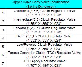
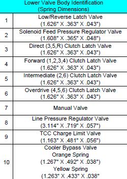
 Overdrive Clutch (4-5-6) Intermediate")
 Planet PTO Gear Single")
9 Component Locations Forward Clutch ( ) Direct Clutch (3-5-R) Overdrive Clutch (4-5-6) Intermediate Clutch (2-6) Low One Way Clutch (Sprag) Low Reverse Clutch Double (Ravigneaux) Planet PTO Gear Single Planet


10 Component Application Chart The two overdrive gears create a shorter ratio. This, combined with different available rear axle ratios, gives the Torqshift the pulling power it needs

11 Shift Speed Chart Gas Engines

12 Shift Speed Chart Diesel Engines


13 Solenoid Body Strategy The solenoid body strategy is a file programmed into the PCM or TCM. The solenoid body tag on the transmission case contains the 13-digit solenoid body strategy and the 8-digit solenoid body identification.

14 Valve Body / Solenoid Replacement Anytime a new valve body is installed, a new solenoid body strategy file is downloaded into the PCM or TCM using a capable scan tool. A replacement solenoid body tag is supplied with the new solenoid body which contains the 13-digit solenoid body strategy and the 8-digit solenoid body identification. The new tag is placed over the original solenoid body tag. If the solenoid body strategy printed on the tag on the solenoid body does not match the solenoid body tag on the side of the transmission case, a new valve body must be installed and the solenoid body strategy must be downloaded into the PCM or TCM or harsh shifts will result.
15 Valve Body / Solenoid Replacement 1. Using the scan tool, select Module Programming and Programmable Parameters then select transmission. Follow the instructions displayed on the scan tool. There are fields to enter the solenoid body eight-digit identification and thirteen-digit strategy recorded from the tag on the main control. 2. NOTICE: If the solenoid body information is not correct, transmission damage or driveability concerns can occur. Enter the solenoid body identification and strategy. The scan tool verifies numbers entered are valid and displays a message if the information is not valid. The scan tool checks to see if the file is present on the scan tool. If the file is present, the technician may proceed with downloading the file to the PCM or Transmission Control Module (TCM). If the file is not present, connect the scan tool to the Professional Technician Society (PTS) server to download the file onto the scan tool or 3. Verify the file is present on the scan tool. If the file is present, go to Step 8. If the file is not present, continue with this procedure. 4. Connect the scan tool to the PTS server. The screen displays a progress bar when connecting to the network. 5. Follow the instructions on the network to download the strategy file to the scan tool.
16 Valve Body / Solenoid Replacement 6. If the scan tool cannot connect to the PTS server, download the file from If the scan tool cannot download a strategy from the web site, a partial strategy is downloaded automatically. 7. Reconnect the scan tool to the vehicle. 8. Follow the instructions displayed on the scan tool. 9. If a new main control was installed, clean the existing solenoid strategy tag on the transmission case and cover It with the replacement solenoid body tag provided with the main control service kit. The scan tool automatically downloads the strategy file or partial strategy file to the PCM or TCM. The scan tool displays a message when its finished downloading the data stating the file was downloaded successfully. 10. NOTICE: If the adaptive drive cycle has not been performed, the customer may feel erratic shifts and driveability concerns. Perform the adaptive drive cycle. Refer to Shift Point Road Test in this section.
 types of solenoids, normally high and normally low solenoids.")

17 Solenoid Replacement The solenoids are calibrated from the factory and are not all the same. There are (2) types of solenoids, normally high and normally low solenoids. The solenoids can be replaced separately, but only with the same type of solenoid. The replacement solenoid band number must match the band number of the solenoid being replaced. The band number is printed on the side of the solenoid and will be a 2, 3, 4 or 5. 4

 Direct (3,5,R) Normally High Shift Solenoid C (SSC) Intermediate (2,6) Normally Low Shift Solenoid D (SSD)")
18 Solenoid Function Ohms Ohms Solenoid Clutch Type Solenoid Type Shift Solenoid A (SSA) Forward (1,2,3,4) Normally Low Shift Solenoid B (SSB) Direct (3,5,R) Normally High Shift Solenoid C (SSC) Intermediate (2,6) Normally Low Shift Solenoid D (SSD) Low/reverse (1,R) Normally Low Shift Solenoid E (SSE) Overdrive (4,5,6) Normally High Line Pressure Control (LPC) solenoid Normally High Torque Converter Clutch (TCC) solenoid Normally Low


19 Solenoid Removal It is recommended to use a scribe or electronic etching tool to mark the solenoids. This will ensure the proper placement after removal.
20 Solenoid Part Numbers SOLENOID BAND # 1 BC3Z-7G383-J 2 BC3Z-7G383-K 3 BC3Z-7G383-L Normally HIGH Solenoid Part Number 4 BC3Z-7G383-M 5 BC3Z-7G383-N SOLENOID BAND # Normally LOW Solenoid Part Number 1 BC3Z-7G383-R 2 BC3Z-7G383-S 3 BC3Z-7G383-T 4 BC3Z-7G383-U 5 BC3Z-7G383-V

21 Easiest Way To Determine NH & NL Solenoids Black Normally High Brown Normally Low

22 Solenoid Apply Chart


23 Case Connector Pin ID Pin Circuit 1 Transmission Solenoid Power Control 1 2 Transmission Solenoid Power Control 2 3 Shift Control Solenoid "A Ohms 4 Shift Control Solenoid "B" Ohms 5 Shift Control Solenoid "C" Ohms 6 Shift Control Solenoid UD" Ohms 7 Shift Control Solenoid "E" Ohms 8 Line Pressure Solenoid Control Ohms 9 TCC Solenoid Control Ohms 10 Transmission Range Sensor Ground 11 Turbine Speed Sensor Signal 12 TSS, OSS, TRS VPWR 13 Transmission Range Sensor Signal 14 Not Used 15 Not Used 16 Not Used 17 Output Shaft Speed Sensor Signal 18 Transmission Temperature Sensor Signal 19 Transmission Temperature Sensor Signal Ground


24 Range Sensor 12 Volts PWM Signal Ground Position % Duty Cycle P R N D M


25 Speed Sensors There is one Turbine and one Output Speed Hall Effect Type Sensor. These sensors produce a five volt D/C signal to the PCM or TCM. OSS TSS 12 Volts Red Signal White Not Used Ground Black


26 Transmission Fluid Temperature Sensor Degrees (F) Degrees (C) Resistance (K) - 40 to to to to to 68 0 to to to to to to to to to to to l to to
 bolts shown in the picture on")

27 Valve Body Overhaul To remove the valve body, remove the nine (9) bolts shown in the picture on the left. To separate the valve body remove the two different size bolts shown in the picture on the right.
 check balls, the (2) relief valves and the pump inlet nozzle.")
28 Valve Body Overhaul Note the location of the (3) check balls, the relief valves and the control valve inlet nozzle for assembly. Remove the (3) check balls, the (2) relief valves and the pump inlet nozzle. (3) (2)

29 Valve Body Overhaul


30 Valve Body Overhaul


")
31 Input Shaft Sealing Ring Replacement Using a suitable tool, remove the 4 solid input shaft and 1 Torque Converter Clutch (TCC) Teflon sealing ring.


32 Input Shaft Sealing Ring Replacement Inspect the overdrive (4,5,6) clutch cylinder and input shaft assembly for damage. Inspect the bushing surfaces, Teflon seal surfaces, ring gear and bushing surfaces for excessive wear or damage. If damage or excessive wear is found, install new components as necessary. Molded sealing rings Bushing Surface Cylinder Bushing

 input shaft Teflon seals into the grooves.")
33 Input Shaft Sealing Ring Replacement Install the Input Shaft Teflon Seal Sizer on the input shaft and adjust it so the bottom edge is lined up just above the top edge of the bottom Teflon seal groove. Lubricate the Input Shaft Teflon Seal Sizer with clean transmission fluid and install a new Teflon seal by sliding it down the Input Shaft Teflon Seal Sizer into the groove. Adjust the Input Shaft Teflon Seal Sizer and install the remaining (3) input shaft Teflon seals into the grooves. Lubricate the Input Shaft Teflon Seal Sizer with clean transmission fluid and install it over the Teflon seals to size the seals. Do the same procedure on the other side of the drum / /4

34 Output Shaft Nut Removal The output shaft nut is coated with Loctite from the factory, then tightened to 150 lb. ft. (about 200 Nm). Failure to loosen the Loctite by applying heat to the output shaft nut can cause damage to the output shaft nut socket. NOTICE: Make sure to clean any debris from the Loctite that may have fallen into the transmission case when removing the output shaft nut. Failure to clean the debris can result in transmission fluid or filter contamination or damage to the transmission. Fixed flange/four-wheel Drive (4WD) shown, slip yoke similar. Apply heat to the output shaft nut to soften the Loctite. Using the output shaft nut socket, remove the output shaft nut.


35 Output Shaft Nut Removal You need to remove this nut to service the low/reverse piston assembly and the rear case seal. The output nut tool is identical to the Torqshift (5R110W) nut just bigger. This nut requires the special tool and lots of heat. The output shaft nut socket is available from Ford, part number # , for about $250 to $300. Although, you can find them through the aftermarket for much less. #
 with the torque converter installed.")
.")

36 Other Tools Required This unit weighs in at a hefty 350 lbs. (almost 160 kilos) with the torque converter installed. This is slightly heavier than the LCT 1000 which weights in at 330 lbs. (150 kilos). Now we can muscle this unit around and risk injuries, or we can take a few minutes and put some tools together that are going to make working on this unit easy and, more importantly safe. Use an engine hoist to get this unit on the bench for a teardown


37 Other Tools Required The input drum assembly must be installed into the transmission as a unit. Using the engine hoist to install this assembly will also be much easier and safe. The easier way to assemble this unit is to stand it on end. You can use an old Allison case as a stand. Ford has a special lifting fixture, tool # , for this operation. #


38 Other Tools Required A duplicate tool can be made fairly quickly with a piece of square tubing, an eye bolt, and two pieces of flat steel. Duplicated Tool
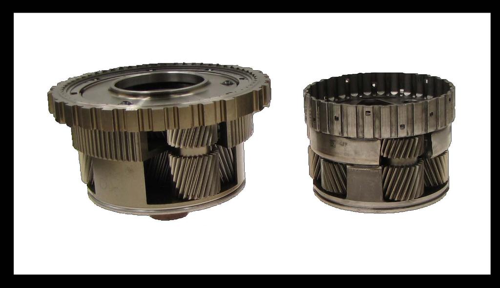

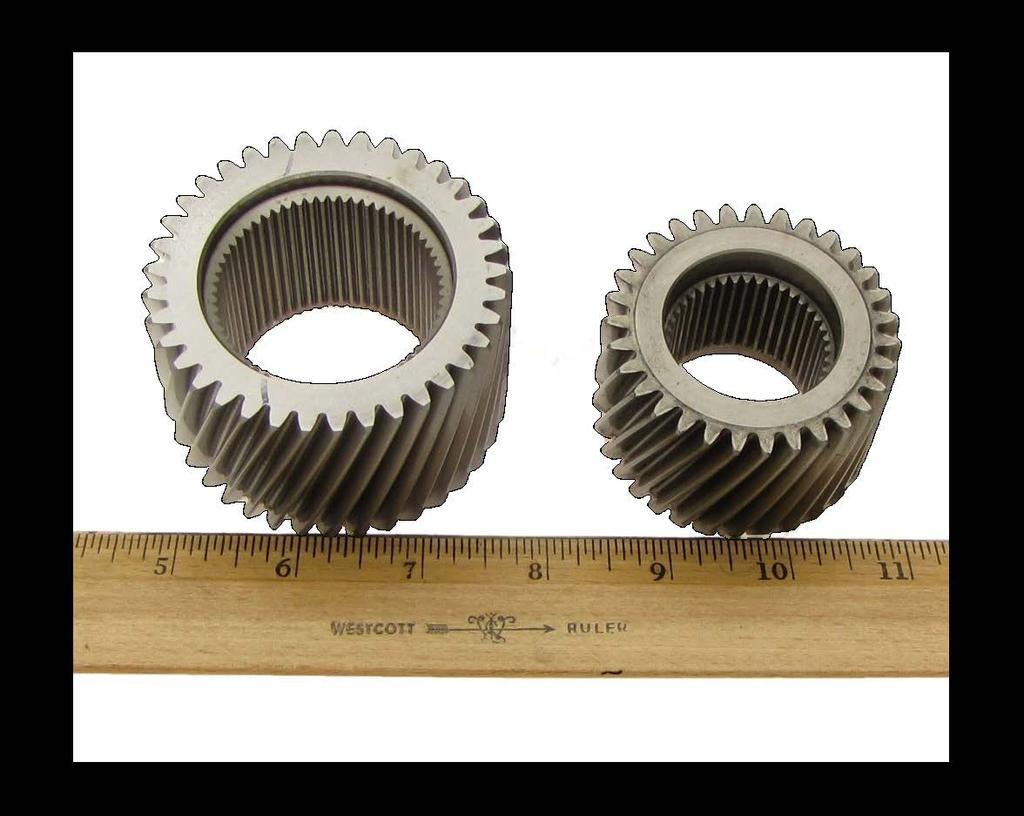

39 Parts Comparison A comparison in some parts sizes to the Ford 5R110W TorqShift.


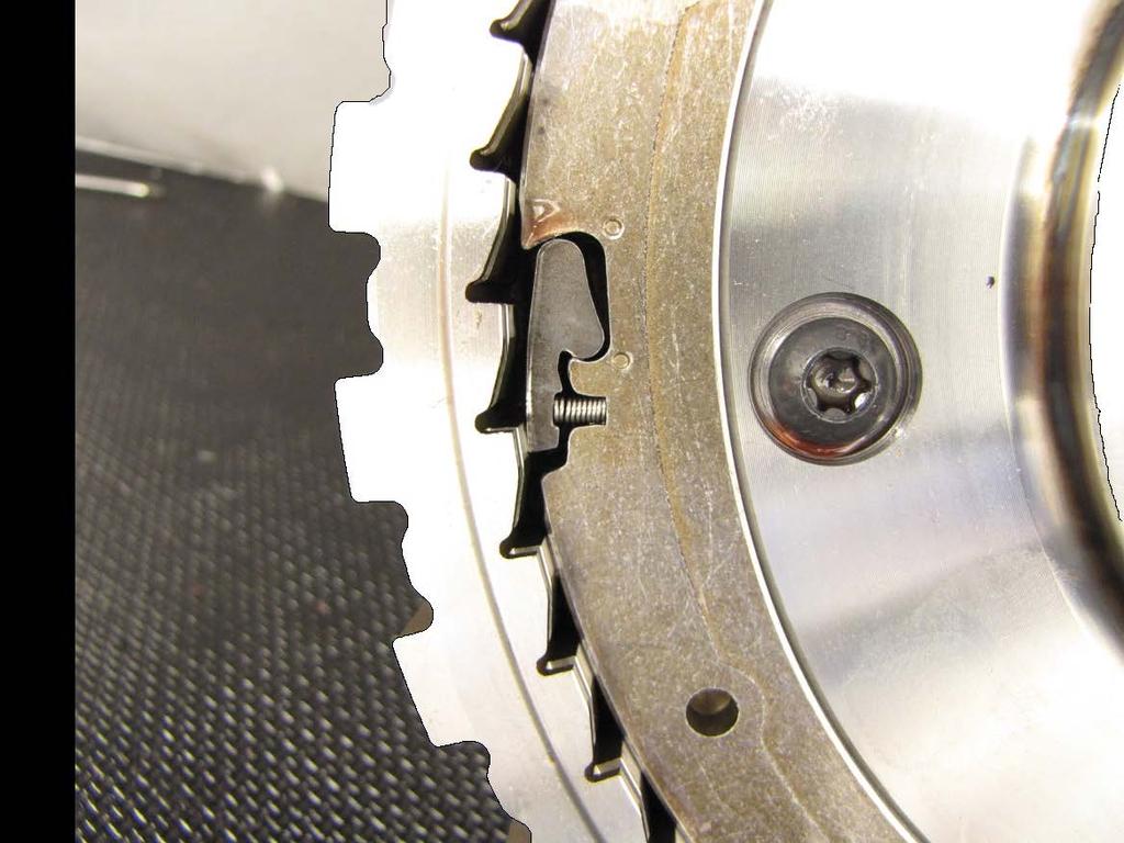
40 One Way Clutch (Diode) A Ford-patented, rocker one-way clutch (diode) is integrated in the carrier to improve 1-2 shift quality through the gear-set


41 Torque Converter Note the spline on the converter hub much like a Honda transmission. There is also an internal spline to drive a PTO gear. The PTO is splined to the engine in this arrangement and spins constantly whenever the engine runs. This eliminates the need to apply another clutch or the torque converter clutch to engage the PTO gear. As you can see here the converter is no lightweight either. Splined Hub Internal Spline For PTO Gear


42 Pump & PTO Gear Some vehicles with a Power Take Off unit will have a PTO gear located here on the stator support. Front sun gear for the single planet splines onto the stator support also


43 Case seals at back and center of case. Case Seals Green Dark Blue Black

44 Valve Body Seals to front of Case Case Seals
45 Case Air Checks & Hydraulic Ports Item Description 1 Converter Inlet 2 Converter Outlet 3 Overdrive Clutch 4 Forward Clutch 5 Pump Inlet 6 Pump Outlet 7 Direct Clutch 8 Torque Converter Clutch 9 Intermediate Clutch 10 Low/Reverse Dynamic 11 Low/Reverse Static
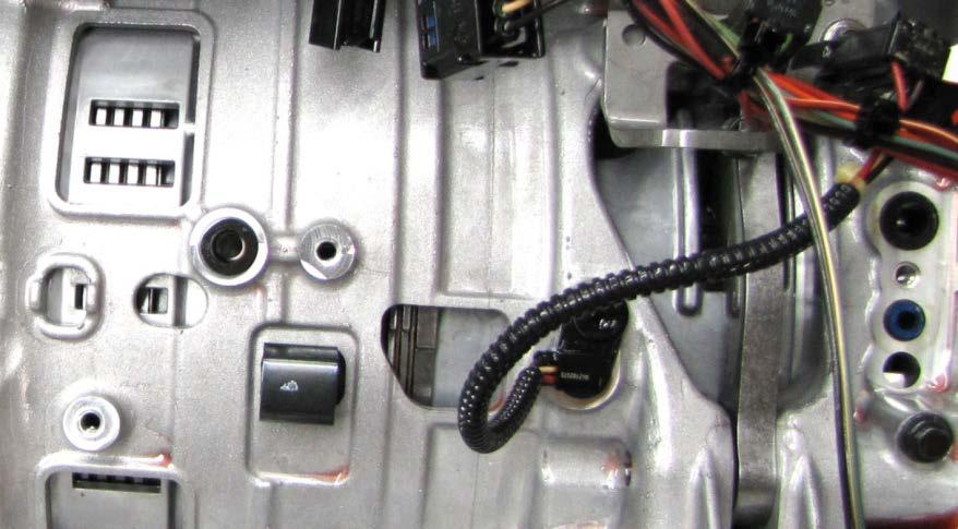
46 Line Pressure Tap Location Line pressure Allan type tap threads are 10mm x 1.00mm located on the left side of the case between the bellhousing and the linkage.
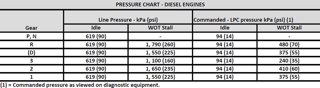
47 Line Pressure Specifications
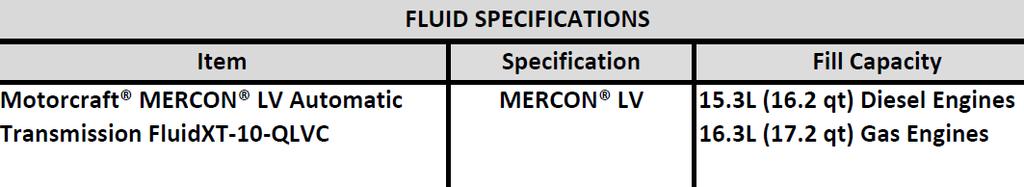
48 Fluid Specifications

49 Clutch Quantity
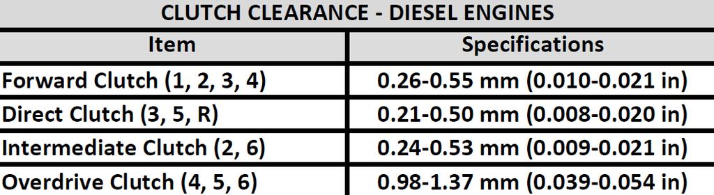
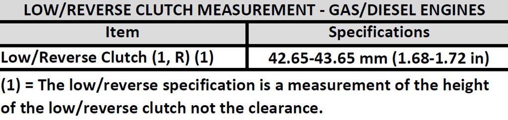
50 Clutch Clearances

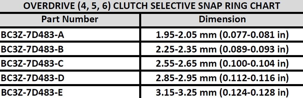
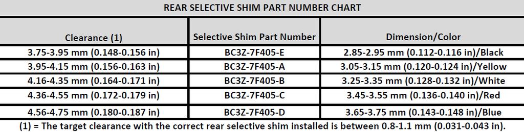
51 Selective Snap Ring Charts

52 Front & Rear Unit Endplay
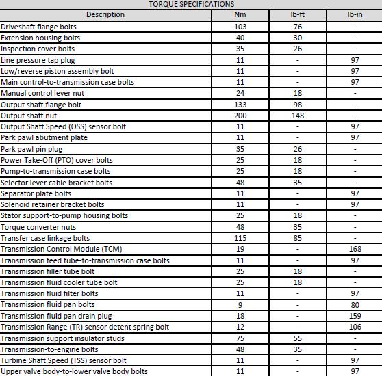

53 Specifications
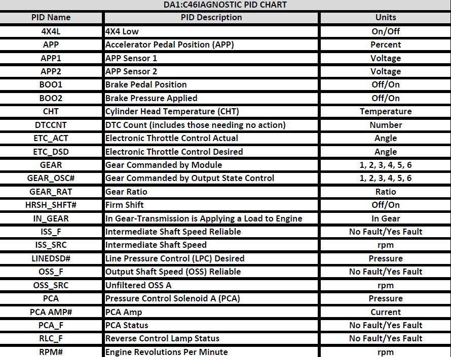
54 Data PID Identification
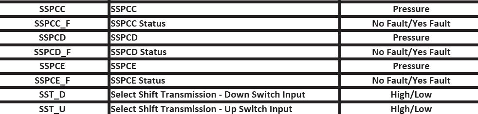
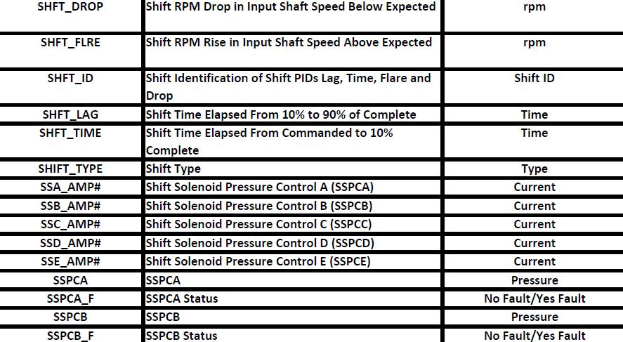
55 Data PID Identification
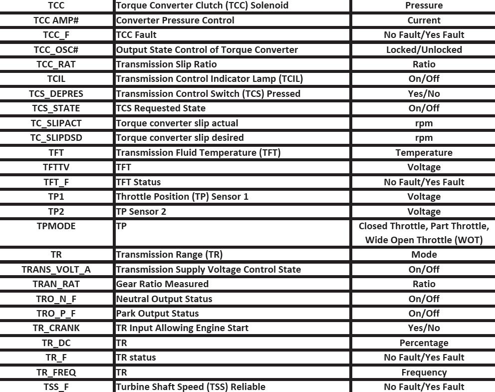
56 Data PID Identification
57 Data PID Identification


58 Today s Presentation Sponsored By: Any Questions? Thank You For Attending Ford 6R140W Intro Webinar 2015 ATRA. All Rights Reserved.
FORD 6R80 UPDATES Presented by: David Chalker ATRA Technical Advisor 6R80
 FORD UPDATES Presented by: David Chalker ATRA Technical Advisor Welcome To Today s Presentation Sponsored By: Any Questions Or Comments Please Send Emails To webinars@atra.com Any Questions That You
Shift Solenoid B (SSB) and Shift Solenoid D (SSD) Inverse Proportional VFS 2761
 and Shift Solenoid D (SSD) Inverse Proportional VFS 2761") Item Description 1 Shift Solenoid A (SSA) Variable Force Solenoid (VFS) 2 Shift Solenoid C (SSC) VFS SSB and SSD use inverse proportional operation. As the current from the PCM decreases, the pressure
Item Description 1 Shift Solenoid A (SSA) Variable Force Solenoid (VFS) 2 Shift Solenoid C (SSC) VFS SSB and SSD use inverse proportional operation. As the current from the PCM decreases, the pressure
DISASSEMBLY. Transmission. All vehicles
 307-01-1 Automatic Transmission 5R44E and 5R55E 307-01-1 DISASSEMBLY Transmission Special Tool(s) Holding Fixture, Transmission 307-262 (T93T-77002-AH) Special Tool(s) Remover, Servo 307-347 (T97T-7D021-A)
DIAGNOSIS AND TESTING
 307-01-1 Automatic Transaxle/Transmission 307-01-1 DIAGNOSIS AND TESTING Pinpoint Tests OSC Equipped Vehicle Special Tool(s) Transmission Fluid Pressure Gauge 307-004 (T57L-77820-A) Special Tool(s) MLP-TR
DIAGNOSIS AND TESTING
 307-01-1 Automatic Transmission 5R55S 307-01-1 DIAGNOSIS AND TESTING Transmission Connector Layouts Connector Reference and Terminal Readings Powertrain Control Module (PCM) C175b 1 Shift Solenoid A (SSA)
DIAGNOSIS AND TESTING
 307-01-1 Automatic Transaxle/Transmission 307-01-1 DIAGNOSIS AND TESTING Transmission Connector Layouts Connector Reference and Terminal Readings Powertrain Control module (PCM) 1 Pressure control solenoid
ASSEMBLY. Transmission Automatic Transmission 5R44E and 5R55E. Special Tool(s)
") 307-01-1 Automatic Transmission 5R44E and 5R55E 307-01-1 ASSEMBLY Transmission Special Tool(s) Holding Fixture, Transmission 307-262 (T93T-77002-AH) Special Tool(s) Installer, Transmission Extension Housing
307-01-1 Automatic Transmission 5R44E and 5R55E 307-01-1 ASSEMBLY Transmission Special Tool(s) Holding Fixture, Transmission 307-262 (T93T-77002-AH) Special Tool(s) Installer, Transmission Extension Housing
2002 Explorer/Mountaineer Workshop Manual
 Page 1 of 20 SECTION 307-01: Automatic Transmission - 5R55W/S 2002 Explorer/Mountaineer Workshop Manual DIAGNOSIS AND TESTING Procedure revision date: 10/20/2004 Pinpoint Tests OSC Equipped Vehicles Special
 Page 1 of 22 SECTION 307-01: Automatic Transaxle/Transmission 4R70E/4R75E ASSEMBLY Procedure revision date: 05/29/2009 Transmission Printable View (1554 KB) Special Tool(s) Air Test Plate, Transmission
AWTF80SC / 81SC (AF21/AF40-6)
") AWTF80SC / 81SC (AF21/AF40-6) FWD 6 Speed 15 35 11 10 40 41 65 50 66 A Pump Assembly 2-6 (B1) Brake Band 3-5 Reverse (C3) Drum 75 Filter 80 20 21 51 52 57 16 17 58 B 24 3-5 Reverse (C3) Clutch 25 81 Front
AWTF80SC / 81SC (AF21/AF40-6) FWD 6 Speed 15 35 11 10 40 41 65 50 66 A Pump Assembly 2-6 (B1) Brake Band 3-5 Reverse (C3) Drum 75 Filter 80 20 21 51 52 57 16 17 58 B 24 3-5 Reverse (C3) Clutch 25 81 Front
FORD 6F50, 6F55 ZIP KIT
 FORD 6F0, 6F ZIP KIT PART NUMBER 6F0-ZIP QUICK GUIDE Parts are labeled here in order of installation. See other side of sheet for details on Zip Kit contents. CAUTION: Ensure shuttle valve is installed
 Page 1 of 10 Main Components and Functions Torque Converter 1 Cover (Part of 7902) 2 Converter Damper Plate 3 O-Ring (Part of 7902) 4 Turbine Assembly (Part of 7902) 5 Selective Spacer 6 Thrust Washer
FORD 6F50, 6F55 ZIP KIT
 FORD 6F0, 6F ZIP KIT PART NUMBER 6F0-ZIP QUICK GUIDE Parts are labeled here in order of installation. See other side of sheet for details on kit contents. CAUTION: Ensure shuttle valve is installed with
5R110W (TorqShift)
") 5R110W (TorqShift) RWD 5 Speed 115 2 40 114 30 41 75 76 55 42 3 56 95 A Pump Body Stator 90 120 121 44 122 57 123 124 58 45 127 77 46 47 59 B Coast Diode Overdrive Planet Center Support 60 61 78 131 99
5R110W (TorqShift) RWD 5 Speed 115 2 40 114 30 41 75 76 55 42 3 56 95 A Pump Body Stator 90 120 121 44 122 57 123 124 58 45 127 77 46 47 59 B Coast Diode Overdrive Planet Center Support 60 61 78 131 99
2002 Ford Explorer AUTOMATIC TRANSMISSIONS' '5R55W/S Diagnosis 2002 AUTOMATIC TRANSMISSIONS. 5R55W/S Diagnosis
 2002 AUTOMATIC TRANSMISSIONS 5R55W/S Diagnosis APPLICATION WARNING: Vehicles are equipped with Supplemental Inflatable Restraint (SIR) system. When servicing vehicle, use care to avoid accidental air bag
Technical Bulletin # 1251
 Transmission: Subject: Application: Issue Date: CD4E TCC Slip Code Diagnosis Ford, Mercury and Mazda May 2009 CD4E TCC Slip Code Diagnosis Once the check engine light illuminates, the transmission will
Shift Solenoids (SS)
") 2011 Mustang Report a problem with this article 307-01 Automatic Transaxle/Transmission 6R80 2011 Mustang IN-VEHICLE REPAIR Procedure revision date: 02/23/2011 Shift Solenoids (SS) Material Item Motorcraft
2011 Mustang Report a problem with this article 307-01 Automatic Transaxle/Transmission 6R80 2011 Mustang IN-VEHICLE REPAIR Procedure revision date: 02/23/2011 Shift Solenoids (SS) Material Item Motorcraft
RE5R05A. A Last Look at the. Welcome back to the final part in our series covering. Part 3 of 3 LET'S PLAY BALL. by Lance Wiggins
 LET'S PLAY BALL A Last Look at the RE5R05A Part 3 of 3 by Lance Wiggins Figure 1 Welcome back to the final part in our series covering the JATCO RE5R05A transmission. So far, we ve covered the computer
chart for this unit. Let s look at some of the gear
 by David Skora recently began seeing a new 6- speed automatic transmission in some Beetle and Passat vehicles. Built by Aisan, this transmission uses the Leppeletier planetary design. All shift timing
2003 E-Series Workshop Manual
 Page 1 of 20 SECTION 307-01B: Automatic Transmission 4R70W 2003 E-Series Workshop Manual ASSEMBLY Procedure revision date: 04/27/2006 Transmission Printable View (1828 KB) Special Tool(s) Dial Indicator
27 E. Front wheel drive. 1. Transmission Description (Ford Focus 2000 only) 4 4 Speed Transmission F
 4 4 Speed Transmission F") 1. Transmission Description (Ford Focus 2000 only) 4 4 Speed Transmission F Front wheel drive 27 E Maximum input torque after torque converter: 270 Lb-ft (365 N-m) Fully Electronic control Note: Mazda
1. Transmission Description (Ford Focus 2000 only) 4 4 Speed Transmission F Front wheel drive 27 E Maximum input torque after torque converter: 270 Lb-ft (365 N-m) Fully Electronic control Note: Mazda
ASSEMBLY. Transmission Automatic Transaxle/Transmission. Special Tool(s) Alignment Set, Fluid Pump 307-S039 (T74P X) Special Tool(s)
 Alignment Set, Fluid Pump 307-S039 (T74P X) Special Tool(s)") 307-01-1 Automatic Transaxle/Transmission 307-01-1 ASSEMBLY Transmission Special Tool(s) Adjustment Set, Transmission Band 307-S022 (T71P-77370-A) Special Tool(s) Alignment Set, Fluid Pump 307-S039 (T74P-77103-X)
307-01-1 Automatic Transaxle/Transmission 307-01-1 ASSEMBLY Transmission Special Tool(s) Adjustment Set, Transmission Band 307-S022 (T71P-77370-A) Special Tool(s) Alignment Set, Fluid Pump 307-S039 (T74P-77103-X)
Pinpoint Tests OSC Equipped Vehicle
 SECTION 307-01: Automatic Transaxle/Transmission 5R55S 2009 Mustang Workshop Manual DIAGNOSIS AND TESTING Procedure revision date: 11/19/2008 Pinpoint Tests OSC Equipped Vehicle Special Tool(s) 73 III
HIGH PERFORMANCE TRANSMISSION PARTS Instructions. Line Pressure Booster Kit. TCC Control Plunger Valve Kit. Line Pressure Modulator Plunger Valve Kit
 Performance Pack Ford 4R100 Part No. HP-4R100-01 Line Pressure Booster Kit Line-to-Lube Pressure Regulator Valve Line Pressure Booster Kit Valve Sleeve O-Rings (2) TCC Control Plunger Valve Kit Front Lube/Drainback
U660E, U660F, U760E, U760F
 Transmission: Subject: Application: Issue Date: Technical Bulletin #1632 U660E, U660F, U760E, U760F Delayed or Harsh Reverse Engagements Toyota August, 2014 U660E, U660F, U760E, U760F Delayed or Harsh
HIGH PERFORMANCE TRANSMISSION PARTS Instructions. Line Pressure Booster Kit. TCC Control Plunger Valve Kit. Line Pressure Modulator Plunger Valve Kit
 Performance Pack Ford 4R100 Part No. HP-4R100-01 Line Pressure Booster Kit Line-to-Lube Pressure Regulator Valve Line Pressure Booster Kit Valve Sleeve O-Rings (2) TCC Control Plunger Valve Kit Front Lube/Drainback
Interchanges are a fact of life for. Interchanges for the E4OD and 4R100 STREET SMART. by Mike Brown
 STREET SMART by Mike Brown Interchanges for the E4OD and 4R100 Figure 1 Figure 2 Interchanges are a fact of life for transmission repair. Maybe you can t get the original part anymore; maybe you just can
6F50 / 6F55 / 6T70 / 6T75
 6F50 / 6F55 / 6T70 / 6T75 FWD 6 Speed 42 80 81 82 83 43 A 41 Differential 84 85 86 87 B 60 Driven Transfer Pinion 50 70 51 169 51 70 C 117 61 139 140 D 5 100 62 Pump Drive 141 90 142 Drive Transfer 71
2002 F-Super Duty /Excursion Workshop Manual
 Page 1 of 25 SECTION 307-01: Automatic Transaxle/Transmission 2002 F-Super Duty 250-550/Excursion Workshop Manual ASSEMBLY Procedure revision date: 05/23/2001 Transmission Special Tool(s) Remover, O-Ring
46RE, 46RH, 47RE, 47RH ZIP KIT
 46RE, 46RH, 47RE, 47RH ZIP KIT PART NUMBER 46-47RHE-ZIP QUICK GUIDE Parts are labeled here in order of installation. See other side of sheet for details on Zip Kit contents. installation Diagram 7 1 Separator
Technical Bulletin Listing 2009
 Technical Bulletin Listing 2009 May, 2009 Transmission Bulletin # # Pages Subject January U140E/U241E 1225 1 Harsh 2-3 Shift After Overhaul GM MP T-Case 1226 10 Introduction 6T70/75 1227 1 Transfer Bolt
Parts are labeled here in order of installation. See other side of sheet for details on Zip Kit contents. installation Diagram
 FORD 6R140 ZIP KIT PART NUMBER 6R140-ZIP QUICK GUIDE Parts are labeled here in order of installation. See other side of sheet for details on Zip Kit contents. installation Diagram WARNING WARNING: If ridge
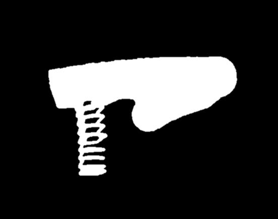
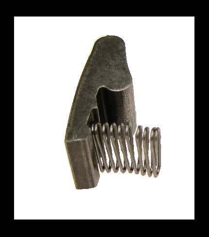
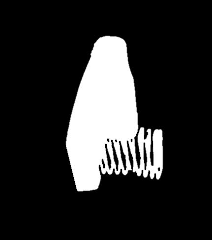
4R70W/4R70/75E. Interchange Information. Updated Spring. Discard. 64 Ford. Anti-Rattle Spring
 64 Ford 4R70W/4R70/75E Interchange Information Anti-Rattle Spring Ford has come up with a better designed anti rattle spring. The updated spring is a V shaped strip of spring steel that won t eat into
Parts are labeled here in order of installation. See other side of sheet for details on Zip Kit contents. installation Diagram
 FORD 6R140 ZIP KIT PART NUMBER 6R140-ZIP QUICK GUIDE Parts are labeled here in order of installation. See other side of sheet for details on Zip Kit contents. installation Diagram WARNING: If ridge and
2006 F-150/Mark LT Workshop Manual
 Page 1 of 14 SECTION 307-01: Automatic Transaxle/Transmission 4R70E/4R75E DIAGNOSIS AND TESTING Procedure revision date: 09/26/2008 Pinpoint Tests OSC Equipped Vehicle Printable View (485 KB) Special Tool(s)
DISASSEMBLY AND ASSEMBLY
 307-01-1 Automatic Transaxle/Transmission 307-01-1 DISASSEMBLY AND ASSEMBLY Transaxle Special Tool(s) Dial Indicator Gauge With Holding Fixture 100-002 (TOOL-4201-C) Special Tool(s) Test Plate Screw Set,
Transmission Electronic Control System
 SECTION 307-01: Automatic Transaxle/Transmission 5R55S 2009 Mustang Workshop Manual DESCRIPTION AND OPERATION Procedure revision date: 05/23/2008 Transmission Electronic Control System Electronic System
Technical Bulletin Listing
 Transmission Bulletin # # Pages Subject Technical Bulletin Listing January, 2007 January U140E, U140F 829A 2 Sprag Rotation V4A51 1054 1 No Power Above 3500 RPM 4T60E 1055 1 Neutral/Shudder During the
Ford CFT 30 Introduction. Presented by: Bill Brayton ATRA Senior Research Technician
 Ford CFT 30 Introduction Presented by: Bill Brayton ATRA Senior Research Technician Connections Handout Webinars@ATRA.com Questions Survey Welcome To Today s Presentation Sponsored By: Thank you to our
Assembly. NOTE: Before beginning assembly, perform/inspect the following:
 Page 1 of 31 Home Account Contact ALLDATA Log Out Help DAN GRIMWOOD DAN GRIMWOOD00002 Select Vehicle New TSBs Technician's Reference Component Search: OK 1997 Ford Truck F 150 2WD Pickup V6-4.2L VIN 2
Subaru EC8 / 4EAT ( )
") Subaru EC8 / 4EAT (1987-98) 4 Speed FWD / AWD 9 105 8 A Input Shaft Differential Differential Housing 10 Pinion 60 30 31 B Reverse Drum 82 95 83 High Drum Reverse Clutch 36 37 39 40 C Forward Hub 42 43
Subaru EC8 / 4EAT (1987-98) 4 Speed FWD / AWD 9 105 8 A Input Shaft Differential Differential Housing 10 Pinion 60 30 31 B Reverse Drum 82 95 83 High Drum Reverse Clutch 36 37 39 40 C Forward Hub 42 43
DPS6 Internal Operation
 DPS6 Internal Operation Presented by: Bill Brayton ATRA Senior Research Technician Welcome To Today s Presentation Sponsored By: Any Questions Or Comments Please Send Emails To webinars@atra.com Any Questions
Jatco 5 Speed ATRA. All Rights Reserved. Printed in U.S.A.
 1 2 3 Table Of Contents Transmission Diassembly... 4 Front Pump... 16 Reverse/High Clutch Drum... 18 Direct Clutch Drum... 22 Low Clutch Drum... 26 Planetary Gearsets... 29 Transfer Gear/Reduction Gear...
GM 4L80-E, 4L85-E SURE CURE KIT
 GM 4L80-E, 4L85-E SURE CURE KIT PART NUMBER SC-4L80E INSTALLATION GUIDE Parts are labeled here in order of installation. See page 2 for details on Sure Cure kit contents. See Sure Cure instruction booklet
GM 4L80-E, 4L85-E SURE CURE KIT
 GM 4L80-E, 4L85-E SURE CURE KIT PART NUMBER SC-4L80E INSTRUCTION BOOKLET Parts are labeled here in order of installation. See page 2 for details on Sure Cure kit contents. See Sure Cure instruction booklet
Transaxle. 1. Mount the transaxle to Bench Mounted Holding Fixture T57L-500-B.
 «1997 Aspire Table of Contents» «Group 07: TRANSAXLE» «Section 07-01: Transaxle, Automatic» «DISASSEMBLY» Transaxle CAUTION: To prevent dirt from entering the transaxle, it should be disassembled and kept
Special Testing Procedures
 SECTION 307-01: Automatic Transaxle/Transmission 5R55S 2009 Mustang Workshop Manual DIAGNOSIS AND TESTING Procedure revision date: 06/30/2009 Special Testing Procedures Special Tool(s) Air Test Plate and
DIAGNOSIS AND TESTING
 307-01-1 Automatic Transaxle/Transmission 307-01-1 DIAGNOSIS AND TESTING Diagnostic Trouble Code Charts Diagnostic Trouble Code Chart P0102, MAF MAF concerns MAF system High/low EPC REFER to the P0103,
Subaru M41 / M41A. FWD 3 Speed 2WD / AWD. C Turbine Shaft Park Pawl. Linkage. Converter Reactor. Pinion. Bell Housing.
 Subaru M41 / M41A FWD 3 Speed 2WD / AWD Park Pawl A Linkage 10 11 B Converter Reactor Bell Housing 13 Pinion C Turbine Shaft Pump Shaft 30 31 D Ring Gear Rear Planet Low Sprag Forward Sun Gear Reverse
Technical Bulletin Listing 2008
 Technical Bulletin Listing 2008 December, 2008 Transmission Bulletin # # Pages Subject January 5R55N/S/W 1149 1 Soft 1-2, 2-3 Shift, Possible Skipped Shift Honda/Acura 1150 1 Filling and Checking the Oil
DIAGNOSIS AND TESTING
 307-01B-1 DIAGNOSIS AND TESTING Special Testing Procedures The special tests are designed to aid the technician in diagnosing the hydraulic and mechanical portion of the transmission. Engine Idle speed
Transmission. Special Tool(s) Installation. All vehicles
 Installation. All vehicles") Transmission Special Tool(s) Installation All vehicles 1. CAUTION: Prior to the installation of the transmission, the fluid, cooler lines and the cooler bypass valve must be cleaned. Transmission failure
Transmission Special Tool(s) Installation All vehicles 1. CAUTION: Prior to the installation of the transmission, the fluid, cooler lines and the cooler bypass valve must be cleaned. Transmission failure
11.AWD Transfer System
 W1860BE.book Page 54 Tuesday, January 28, 2003 11:01 PM 11.AWD Transfer System A: MPT MODELS 1. GENERAL This all-wheel-drive (AWD) transfer system uses an electronically controlled multi-plate type transfer
2001 Chevrolet Corvette AUTOMATIC TRANSMISSIONS Hydra-Matic 4L60-E - Overhaul
 2001-03 AUTOMATIC TRANSMISSIONS Hydra-Matic 4L60-E - Overhaul APPLICATION CAUTION: Flush oil cooler and oil cooler lines prior to transmission installation. Oil cooling system contamination may cause premature
Table of Contents INTRO
 GENERAL ALL Wheel Drive Systems General System Overview...2 Transfer Coupling...3 Diagnostics, Tire Wear, Codes...4 Rolling Circumference Test...5 Getrag 760 T-Case Introduction and Service Information...6
TION AND OPERATION Procedure revision date: 01/22/1999
 TION AND OPERATION Procedure revision date: 01/22/1999 Main Components and Functions AX4S Main Components http://www.fordtechservice.dealerconnection.com/pubs/content/~wsww/~mus~len/20/sww71006.htm (1
Allison LCT1000. Presented by: Mike Souza ATRA Senior Research Technician Allison LCT1000 Webinar 2014 ATRA. All Rights Reserved.
 Allison LCT1000 Presented by: Mike Souza ATRA Senior Research Technician Allison LCT1000 Webinar 2014 ATRA. All Rights Reserved. Generation Changes 2000 to 2005 Gen I Allison LCT1000 are 5 speeds. In
2007 Jeep Truck Liberty 4WD V6 3.7L VIN K
 2007 Jeep Truck Liberty 4WD V6 3.7L VIN K Vehicle» Transmission and Drivetrain» Automatic Transmission/Transaxle» Service and Repair» Overhaul» Assembly ASSEMBLY NOTE: If the transmission assembly is being
Technical Bulletin Listing 2009
 Technical Bulletin Listing 2009 Transmission Bulletin # # Pages Subject January U140E/U241E 1225 1 Harsh 2-3 Shift After Overhaul GM MP T-Case 1226 10 Introduction 6T70/75 1227 1 Transfer Bolt Eliminated
ZF6HP19/26/32 (Generation 1), Ford 6R60, 6R75, 6R80, ZF6HP21/28/34 (Generation 2)
, Ford 6R60, 6R75, 6R80, ZF6HP21/28/34 (Generation 2)") Valve Body Identification ZF6HP19/26/32 (Generation 1), Ford 6R60, 6R7, 6R80, ZF6HP21/28/34 (Generation 2) IDENTIFICATION GUIDE Valve components differ between Generation 1 (ZF6HP19/26/32), Ford 6R60,
Valve Body Identification ZF6HP19/26/32 (Generation 1), Ford 6R60, 6R7, 6R80, ZF6HP21/28/34 (Generation 2) IDENTIFICATION GUIDE Valve components differ between Generation 1 (ZF6HP19/26/32), Ford 6R60,
AUTOMATIC TRANSMISSIONS. General Motors Corp. Hydra-Matic 4L60-E Overhaul
 1997-98 AUTOMATIC TRANSMISSIONS General Motors Corp. Hydra-Matic 4L60-E Overhaul APPLICATION TRANSMISSION APPLICATIONS Application Corvette Transaxle 4L60-E IDENTIFICATION The 4L60-E transmission can be
SECTION Automatic Transaxle/Transmission 6R80
 307-01-i Automatic Transaxle/Transmission 6R80 307-01-i SECTION 307-01 Automatic Transaxle/Transmission 6R80 CONTENTS PAGE Main Control... 307-01-2 307-01-2 Automatic Transaxle/Transmission 6R80 Main Control
Diagnostic Trouble Code (DTC) Charts
 Charts") SECTION 307-01: Automatic Transaxle/Transmission 5R55S 2009 Mustang Workshop Manual DIAGNOSIS AND TESTING Procedure revision date: 06/30/2009 Diagnostic Trouble Code (DTC) Charts DTC Chart **May also be
SECTION 307-01: Automatic Transaxle/Transmission 5R55S 2009 Mustang Workshop Manual DIAGNOSIS AND TESTING Procedure revision date: 06/30/2009 Diagnostic Trouble Code (DTC) Charts DTC Chart **May also be
TRANSMISSION PARTS Instructions. Solenoid Regulator Valve Retainer Shim. Main Pressure Regulator Valve
 TRANSMISSION PARTS Instructions Sure Cure Kit Part No. SC-AODE NOTE: This kit is fully compatible with '91 '95 only. Identified by alignment pins 13mm heads. This kit will not work on '96 Later units.
4T80E. FWD 4 Speed Primary/Secondary Pump. 2-3 Accum. Valve Body Cover Channel Plate Upper Valve Body.
 4T80E FWD 4 Speed 2 190 A 191 54 55 250 Valve Body Cover 156 Primary/Secondary Pump 155 129 151 152 157 3 Upper Valve Body 2-3 Accum. 183 53 182 Channel Plate 20 21 60 135 91 195 72 73 B 33 2nd Clutch
Automatic Transmission 5R44E and 5R55E
 307-01-1 Automatic Transmission 5R44E and 5R55E 307-01-1 IN-VEHICLE REPAIR Main Control Valve Body Special Tool(s) Aligner, Valve Body 307-333 (T95L-70010-B) Aligner, Valve Body 307-334 (T95L-70010-C)
2000 Jeep Truck Cherokee 4WD L6-4.0L VIN S
 2000 Jeep Truck Cherokee 4WD L6-4.0L VIN S Vehicle» Transmission and Drivetrain» Automatic Transmission/Transaxle» Service and Repair» 30-40LE (AW4) 4 Speed» Overhaul (Transmission)» Disassembly DISASSEMBLY
AODE ( 96 & LATER) SC-AODE-1. Transmission Reconditioning Kit FULL COMPATIBILITY IMPORTANT VALVE BODY PARTS REASSEMBLY PARTS
 SC-AODE-1. Transmission Reconditioning Kit FULL COMPATIBILITY IMPORTANT VALVE BODY PARTS REASSEMBLY PARTS") AODE ( 96 & LATER) Transmission Reconditioning Kit FULL COMPATIBILITY SC-AODE-1 Full compatibility with 1996 and later units. Identified by alignment pins with 10mm head and.173" pin diameter. IMPORTANT
AODE ( 96 & LATER) Transmission Reconditioning Kit FULL COMPATIBILITY SC-AODE-1 Full compatibility with 1996 and later units. Identified by alignment pins with 10mm head and.173" pin diameter. IMPORTANT
DIAGNOSIS AND TESTING
 307-01-1 Automatic Transaxle/Transmission 307-01-1 DIAGNOSIS AND TESTING Special Testing Procedures Special Tool(s) Air Test Plate, Transmission 307-405 Transmission Fluid Pressure Gauge 307-004 (T57L-77820-A)
Toyota U140 / U240. FWD 4 Speed. D B-1 Accumulator. Pinion. Differential 120. Bell Housing. Forward Drum. Pump Body Stator. Case
 Toyota U140 / U240 FWD 4 Speed Pinion 11 12 A 40 3 118 Differential 120 Bell Housing 10 B 85 Pump Body Stator 29 30 Forward Drum C Case 1st / Reverse Clutch 79 D B-1 Accumulator C-2 Accumulator 150 SLT
Valve Body Rebuild Tips & Techniques
 Ford 4r44e, 4r55e, 5r44e, 5r55e zip Kit PaRT NUMBER 4r44e-5r55e-zip Installation & TESTING BOOKLET Torque Specifications Band Adjuster Lock Nut 35 to 45 ft-lb Transmission Oil Pan Bolt 115 to 133 in-lb
F o r d I n s t a l l a t i o n I n s t r u c t i o n s
 1 DO NOT USE WATER-BASED TRANSMISSION FLUSHING FLUID THE LINING IN THE CONVERTOR CLUTCHES WILL DISINTIGRATE, RENDERING THE CONVERTOR USELESS AND WARRANTY WILL BE VOIDED. BD PERFORMANCE TRANSMISSION F o
AW55-50SN / AF23/33-5 / RE5-F22A
 AW55-50SN / AF23/33-5 / RE5-F22A FWD 5 Speed 11 10 51 A Pump Assembly 65 B Filter C 12 Case D 84 SLT SLU 82 83 116 SLS Differential 150 Valve Body 115 81 1 80 Shift Solenoids Band Servo Linkage Assembly
Hyundai A4AF1/2/3 & A4BF1/2/3
 Hyundai A4AF1/2/3 & A4BF1/2/3 FWD 4 Speed 10 50 11 51 100 20 52 101 53 A Pump Body Stator Direct Drum 36 37 110 45 B Forward Clutch Forward Hub Shell / Kickdown Drum Kickdown Band 55 23 55 56 56 65 C Reverse
6L45 / 6L50 / 6L80 / 6L90
 6L45 / 6L50 / 6L80 / 6L90 RWD 6 Speed 39 79 3 44 4 153 155 80 7 159 45 8 81 92 A Pump Assembly Stator 52 53 57 55 56 173 174 95 93 B 1-2-3-4 Clutch 3-5 Reverse Clutch Input Planet Input Sun Gear 97 98
AUTOMATIC TRANSMISSIONS Mitsubishi F3A20 Series TRANSMISSION APPLICATION TABLE
 Article Text ARTICLE BEGINNING AUTOMATIC TRANSMISSIONS Mitsubishi F3A20 Series APPLICATION TRANSMISSION APPLICATION TABLE Vehicle Application Transmission Model Colt 3-Speed (1990-94)... F3A21 Colt Vista
6T30/6T40/6T45 - AUTOMATIC TRANSMISSION
 2010 GMC Truck Terrain AWD L4-2.4L Vehicle > ALL Diagnostic Trouble Codes ( DTC ) > Testing and Inspection > P Code Charts > P0717 6T30/6T40/6T45 - AUTOMATIC TRANSMISSION DTC P0716 or P0717 Diagnostic
2013 NATEF Task Area A-2 Automatic Transmission7-2013
 2013 NATEF Task Area A-2 Automatic Transmission7-2013 A. General Transmission & Transaxle Diagnosis B. Transmission & Transaxle Maintenance & Adjustment C. In-Vehicle Transmission & Transaxle Repair D.
Figure 1: LCT 1000 mounted on a dyno for the purpose of this article.
 A Fast Fix for the Allison LCT 1000 A Fast Fix for the Allison LCT 1000 by David Skora Figure 1: LCT 1000 mounted on a dyno for the purpose of this article. Most Duramax trucks are bought to do work. Most
TRANSMISSION PARTS Instructions
 TRANSMISSION PARTS Instructions Sure Cure Kit Part No. SC-4T65E GM 4T65-E Valve Body Parts Boost Valve Kit 84754-30K Patent No. 6,832,632 TCC Apply Valve Kit 84754-43K Patent No. 7,100,753 TCC Regulated
Introduction to the GM 6L80. Presented By: Steve Garrett
 Introduction to the GM 6L80 Presented By: Steve Garrett 6L80 (RPO MYC) Introduction The first of ten 6 speed automatics was introduced in the 2006 model year. The 6L80 (RPO MYC) is currently available
2012 NATEF Task Area A 2 Automatic Transmission
 2012 NATEF Task Area A 2 Automatic Transmission A. General Transmission & Transaxle Diagnosis B. Transmission & Transaxle Maintenance & Adjustment C. In Vehicle Transmission & Transaxle Repair D. Off Vehicle
Ford 6R60/75/80 (ZF6HP26)
") Ford 6R60/75/80 (ZF6HP26) RWD 6 Speed 30 2 3 39 75 76 40 41 42 A Pump Body Forward Drum (A) 77 43 14 15 B 18 O.Dr. Drum (E) O.Dr. Clutch (E) 19 45 78 45 C Direct Drum (B) Direct Clutch (B) 22 23 D Intermediate
Ford 6R60/75/80 (ZF6HP26) RWD 6 Speed 30 2 3 39 75 76 40 41 42 A Pump Body Forward Drum (A) 77 43 14 15 B 18 O.Dr. Drum (E) O.Dr. Clutch (E) 19 45 78 45 C Direct Drum (B) Direct Clutch (B) 22 23 D Intermediate
F4A41 / 42 / 51 / A / B / F5A51/A
 F4A41 / 42 / 51 / A / B / F5A51/A FWD 4 & 5 Speed 5 Speed Only A Pinion Driven Transfer Direct Planet B 50 Bell Housing. 11 Pinion Driven Transfer 11 66 Drive C Filter Differential 51 TISS 67 68 TOSS 24
Advanced Auto Tech Worksheet Auto Trans & Transaxle Chapter 40 Pages Points Due Date
 Advanced Auto Tech Worksheet Name Auto Trans & Transaxle Chapter 40 Pages 1173 1215 107 Points Due Date 1. Automatic transmissions are operated by hydraulics as well as electronics to select according
2009 marks the 20-year anniversary
 Old and New Fixes for Ford s Family of HD Transmissions PLAYING WITH FIRE Old and New Fixes for Ford s Family of by Jon Rodriguez HD Transmissions 2009 marks the 20-year anniversary for the E4OD. Yes,
INSTALLATION INSTRUCTIONS 68RFE ZERO-TUNE.
 1 TORQUE SPECIFICATIONS 2 IMPORTANT: The RevMax ZeroTune kit requires the transmission to be removed from the vehicle and be partially disassembled. It is recommended that a professional transmission technician
ALLISON 1000 SIGNATURE SERIES
 ALLISON 1000 SIGNATURE SERIES 2001-2010 DURAMAX GPZ 1 FLUID CAPACITY INSTALLATION In our RevMax performance transmission we require you to use DEXRON 3 fluid and are shipped empty due to the regulations
Toyota A750 E/F A760 E/F A761 Introduction. Sponsored By: Presented by: Steve Garrett ATRA
 Toyota A750 E/F A760 E/F A761 Introduction Sponsored By: Presented by: Steve Garrett ATRA Today s Presentation Sponsored By: Lwiggins@ATRA.com Connections Handout Questions Survey Toyota A750 E/F Common
2007 Dodge Nitro R/T
 ASSEMBLY AUTOMATIC TRANSMISSION - 42RLE NOTE: If the transmission assembly is being reconditioned (clutch/seal replacement) or replaced, it is necessary to perform the TCM QUICK LEARN Procedure using the
Chrysler 46RE, 46RH, 47RE, 47RH SURE CURE KIT
 Chrysler 46RE, 46RH, 47RE, 47RH SURE CURE KIT PART NUMBER SC-46-47RHE-OS INSTALLATION GUIDE Parts are labeled here in order of installation. See other side of sheet for details on Sure Cure kit contents.
2007 Dodge Nitro R/T
 1 - TURBINE 2 - IMPELLER 2007 Dodge Nitro R/T CONVERTER-TORQUE DESCRIPTION TORQUE CONVERTER Fig. 267: Cutaway View Of Torque Converter Fig. 268: Impeller 2007 Dodge Nitro R/T 3 - STATOR 4 - INPUT SHAFT
Automatic Transmissions & Transaxles
 ATASA 5 th Study Guide Chapter 40 Pages 1173 1215 Automatic Transmissions /Transaxles 107 Points Be Certain to Read the Summary 1. Automatic transmissions are operated by hydraulics as well as electronics
Transtar Part Numbering
 000- -099 No Prefix = P & R Kits No Suffix = Kits w/ Cork Pan Gaskets or Default Gasket* No Prefix = Kits w/ Ray/Borg/Dynax Frictions * Default Gasket = Late models that are originally equipped with No
INTERMITTENT TRANSMISSION CLUTCH SHUDDER TSB DPS6 AUTOMATIC TRANSMISSION AND/OR TRANSMISSION FLUID LEAK
 INTERMITTENT TRANSMISSION CLUTCH SHUDDER TSB 13-9-4 DPS6 AUTOMATIC TRANSMISSION AND/OR TRANSMISSION FLUID LEAK FORD: 2011-2014 Fiesta 2012-2014 Focus This article supersedes TSB 13-4-5, 12-4-6 and c. Clutch
Automatic Transmission Basics
 Section 1 Automatic Transmission Basics Lesson Objectives 1. Describe the function of the torque converter. 2. Identify the three major components of the torque converter that contribute to the multiplication
INDEX AUTOMATIC TRANSMISSION SERVICE GROUP SW 107TH AVENUE MIAMI, FLORIDA (305) Copyright ATSG 2004
 Copyright ATSG 2004") FORD E4OD "UPDATE HANDBOOK" INDEX VALVE BODY AND CHECKBALL CHANGES THRU 1996... 1989-1995 VALVE BODY CHECKBALL LOCATIONS... 1996 VALVE BODY CHECKBALL LOCATIONS... EARLY 1989 CASE CHECKBALL LOCATIONS...
FORD E4OD "UPDATE HANDBOOK" INDEX VALVE BODY AND CHECKBALL CHANGES THRU 1996... 1989-1995 VALVE BODY CHECKBALL LOCATIONS... 1996 VALVE BODY CHECKBALL LOCATIONS... EARLY 1989 CASE CHECKBALL LOCATIONS...
 Page 1 of 9 2004 Ford Pickup 5.4L Eng VIN L F250 Super Duty 1Search Print Date: P0720 Pinpoint Test F: Turbine Shaft Speed (TSS) And Output Shaft Speed () Sensors NOTE: Refer to the Output Shaft Speed
LX AUTOMATIC TRANSMISSION NAG1 - SERVICE INFORMATION TABLE OF CONTENTS
 LX AUTOMATIC TRANSMISSION NAG1 - SERVICE INFORMATION 21-495 AUTOMATIC TRANSMISSION NAG1 - SERVICE INFORMATION TABLE OF CONTENTS page AUTOMATIC TRANSMISSION NAG1 - SERVICE INFORMATION DESCRIPTION...496
4T65E. FWD 4 Speed. E Final Drive Sun Gear Shaft Final Drive Ring Gear Output Shaft. Side Cover. 2nd Clutch Drum. Support
 4T65E FWD 4 Speed 2 102 181 185 187 183 182 182 186 141 150 300 150 A 3 184 B Side Cover Output Shaft 153 152 151 267 69 125 97 135 268 70 71 146 38 39 37 36 40 C Support Rev. Band 2nd Clutch Drum 2nd