Allison LCT1000. Presented by: Mike Souza ATRA Senior Research Technician Allison LCT1000 Webinar 2014 ATRA. All Rights Reserved.
|
|
|
- Rosaline McCarthy
- 6 years ago
- Views:
Transcription


1 Allison LCT1000 Presented by: Mike Souza ATRA Senior Research Technician Allison LCT1000 Webinar 2014 ATRA. All Rights Reserved.
2
3
4 Generation Changes 2000 to 2005 Gen I Allison LCT1000 are 5 speeds. In 2004 the G solenoid was added to lower line pressure in Park & Neutral to reduce pump whine because these units worked on full line pressure. Most pump whine complaints could be heard more on gas vehicles while sitting in park and neutral. There were also several updates to the pump for this concern Gen II the Allison transmission became a 6 speed. In 2006 the Trim Solenoids were changed to Pressure Control Solenoids. The neutral start back up switch was changed to an internal mode switch Gen III Allison is still a 6 speed, the G solenoid was eliminated and a Main Modulating Solenoid was added to control line pressure Gen IV the Allison transmission became an 8 speed. Along with these changes there are many major changes to internal components as well. The some internal components cannot be interchanged, unless as complete assemblies. Other components cannot be interchanged at all.
 Transmission")

5 LCT1000 Identification (1) Date of Manufacture (2) Transmission Identification Number (3) Engineering Feature Configuration Number (4) Serial Number
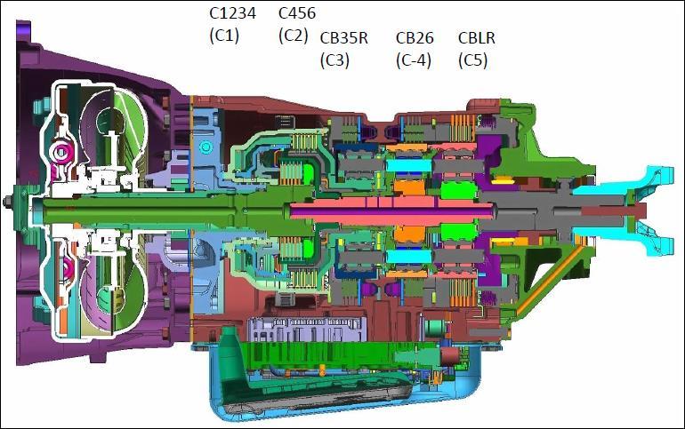
6 Component Identification

7 5 & 6 Speed Apply Chart Up to 2005 Gen I Allison LCT1000 are all 5 speeds. In 2006 to acquire six forward gears the C3 Clutch is released and the C4 Clutch is re-applied.

8 Speed Sensors The three Speed Sensors are two wire pulse generators that produce an A/C pulsed voltage. The generated A/C voltage can vary from 150mV 15V depending upon RPM. The wiring to the sensors have a shielded ground to prevent electro magnetic interference EMI. Engine Speed Sensor Turbine Speed Sensor Output Speed Sensor (2WD) Output Speed Sensor (4WD) Located on Transfer Case 4 Wheel Drive Case shown

9 Speed Sensors The Engine Speed Sensor monitors the protrusions (dimples) on the torque converter. The gap between the engine speed sensor and the converter dimples is approximately Damage to any of the converter dimples will result in an uneven signal from the engine speed sensor to the TCM causing a complaint of torque converter surge without setting codes. This drop in signal can be monitored with an oscilloscope and may not be caught on scan tool data. This sensor was eliminated in Eliminated in 2007


10 Speed Sensors The Turbine Speed Sensor monitors the teeth on the PTO drive gear attached to the C1/C2 Clutch Drum. The Output Sensor monitors an exciter wheel located on the output shaft on 2 wheel drive models or on the transfer case on 4 wheel drive units. C1/C2 Clutch Drum PTO Drive Gear Output Speed Sensor (2WD) PTO Drive Gear 4 Wheel Drive Case shown
 can be used on an AS68RC in")

11 Solenoid Identification Trim Sol A N/C Shift Sol. E N/C Shift Sol. D N/C Trim Sol B N/O Sol F TCC PWM N/C Main Valve Body Trim Sol B (N/O) can be used on an AS68RC in place of a normally applied solenoid. Dodge sells the AS68RC linear type solenoids with the valve body only approx. $3500. On/off solenoids & pressure switches sold separately. The Allison Trim Solenoid B is approx. $120

12 Solenoid Identification Shift Sol C N/C Shift Valve Body


13 Solenoid Identification In 2004 the G Solenoid was added to reduce line pressure at a stand still to prevent pump noise. Trim Sol A N/C Not Drilled in 2004 to 2005 Trim Sol B N/O Shift Sol. E N/C Shift Sol. D N/C Sol F TCC PWM N/C Pressure Reducing Solenoid G PWM The Internal Harness and TCM also changed with the addition of the G solenoid

14 Separator Plate Change Original Separator Plate Original Separator Plate

15 Solenoid Identification 2006 to 2009 Pressure Control Solenoid A Pressure Control Solenoid B Shift Sol. E N/C Shift Sol. D N/C Sol F TCC PWM N/C Tube was added & casting drilled in the 2006 models Pressure Reducing Solenoid G PWM Changes made to the hydraulics also with the tube added


16 Other Changes Made In 2006


17 Solenoid Identification In 2010 the G Solenoid was eliminated and a Main Modulating Solenoid was added to control line pressure like most transmissions. Pressure Control Sol 1 PCS1 Pressure Control Sol 2 PCS2 Shift Sol 3 SS3 Shift Sol 2 SS2 TCC Pressure Control Sol TCC/PCS Correct Plastic Plug Shift Sol 1 SS1 Main Modulating Solenoid MMS Solenoid Retainer Bracket Extension Faces Downward Wrong
 solenoids. The hydraulic pressure provided by these solenoids is proportional to the current being commanded.")
18 Trim Solenoid Operation Trim Solenoids A and B control the apply of the oncoming clutch and the release of the off-going clutch as well as the holding pressure to the five clutch assemblies. The Trim Solenoids are referred to as Pressure Proportional to Current (PPC) solenoids. The hydraulic pressure provided by these solenoids is proportional to the current being commanded. The Trim Solenoids operate on a frequency of 1000 Hz. Trim Solenoid A is a Normally Closed solenoid (N/C) supplying 86 psi with no current and no trim pressure at full current. Trim Solenoid A is used for limp-home (failsafe) in the case of a loss of power or TCM failure. Trim Solenoid B is a Normally Open solenoid (N/O) and supplies no pressure with low current.

 solenoids.")
19 TCC & Shift Solenoid Operation The TCC solenoid a normally closed (N/C) pulse width modulated (PWM). It operates at a frequency of 100 Hz during a shift. The percentage of time the voltage is ON during each cycle is called the solenoid duty cycle. The Shift Solenoids C, D and E are normally closed (N/C) solenoids. They supply full line pressure when on or exhaust line pressure to each of the corresponding Shift Valves C, D, and E. E D C TCC

 Shift \"C\" Signal (B) Shift \"D\" Signal (C) Shift \"E\" Signal (D) Reverse Switch Signal (E) Temp Sensor High (F) Temp Sensor Low")
20 Pressure Switch Manifold PMS The Pressure Switch Manifold on an Allison transmission works differently than what we are accustomed to on other General Motors transmissions. It sends signals to the PCM when the shift valves move instead of the manual valve movement. (A) Shift "C" Signal (B) Shift "D" Signal (C) Shift "E" Signal (D) Reverse Switch Signal (E) Temp Sensor High (F) Temp Sensor Low Present PSM 2010 & later C Shift Valve N/O Previous PSM Not Used E Shift Valve N/O Temp Sensor Reverse N/C D Shift Valve N/O
 Circuit Low Voltage These codes can be caused by a fault in a clutch circuit, valve body, shift solenoid, or faulty pressure switch circuit.")
21 PSM Codes P0842, P0847, P0872 DTC Descriptions: P0842 Trans Fluid Pressure Switch 1 Solenoid (C) Circuit Low Voltage P0877 Trans Fluid Pressure Switch 2 Solenoid (D) Circuit Low Voltage P0872 Trans Fluid Pressure Switch 3 Solenoid (E) Circuit Low Voltage These codes can be caused by a fault in a clutch circuit, valve body, shift solenoid, or faulty pressure switch circuit. To verify if a solenoid is at fault, solenoids C-D-E can be swapped. If code transfers with solenoid swap, replace the faulty solenoid. Air test the unit to assure clutch assemblies hold. The valve body is very sensitive to dirt and the valves are easily stuck. Make sure all magnets are installed (both pan and spin on filter). Flat sand valve body and torque all bolts evenly. C D E
 of the switch s should read open and one (1) should read closed. Start the engine and the switch s should read opposite states on scan data.")
22 Pressure Switch Manifold Logic Testing the Pressure Switch System; Use the chart as a reference. Turn the ignition key on with engine off. Three (3) of the switch s should read open and one (1) should read closed. Start the engine and the switch s should read opposite states on scan data. PS 1 = C PS 2 = D PS 3 = E PS 4 = R
")


23 Neutral Start Back Up Switch (NSBU) Wrong Gear Starts / No Back Up Lights / P0705 Update (Tan) PN Inside Seal Added Plastic Outer Weather Shield Early Black Dual Connector 7 Pin repair pigtail harness (all wires white) w/heat shrink connectors PN Pin repair pigtail harness (all wires white) w/heat shrink connectors PN Note: use old connector to match wiring Park/Neutral Back Up Switch (PNBU) 2004 Changed to Single Connector Plastic Outer Weather Shield

24 2006 Update Internal Mode Switch (IMS)

25 Internal Mode Switch Logic Always use scan data when diagnosing the IMS switch. The following chart shows the sequence of on / off operations
26 Internal Mode Switch Installation Care needs to be taken when replacing the Internal Mode Switch (IMS) in the LCT1000 units. The retaining pin holding the manual shaft into the case is set at a specific length/height (measure and record). To prevent damage to the roll pin, insert a drill into the roll pin to prevent the pin from collapsing when being removed. When assembling use the following procedures: 1: Place the new IMS in position in the case. Rotate the detent to connect the park rod. Install manual shaft through the IMS 2: Seat the shaft and install the spherical pin (remember pre-set) 3: Torque IMS retaining bolt to 92 lb. in. (T27 bit) Install the valve body and pan for fill. Important: Fast learn adapt procedure must be performed after switch replacement Pin not illustrated Pin installed height is to above the surface. Special tool number J43766

 and added feed")


27 Main Valve Body The valve and spring dimensions will vary per model year with the changes to solenoids (2004) and added feed pipe (2006) along with other shift related updates X.552 X X.387 X X.596 X X.496 X X.387 X Accumulator Valves X.308 X X.387 X No Check Balls 6 7

28 Shift Valve Body A restricted Solenoid Feed Filter will cause a no movement condition without setting any codes. The PRNDL message on the dash will read Shift Inhibited. Range signal will read correctly on scan tool data. Always remove and clean or replace the filter. Solenoid Feed Filter X.553 X X.433 X X.433 X X.433 X No Check Balls
29 Updates The LCT 1000 has undergone a major update for the model years. The updates were designed to address the increased engine torque available from the updated Dura Max Diesel engine, improve fuel economy and to address some common concerns. CAUTION: 2010 updated shaft parts must be used as a set. Replacing individual shafts with 2010 updated shaft parts to service pre 2010 transmissions, so that a mix of pre 2010 and 2010 shafts are operating together, may cause transmission damage. Converter: LU capacity increase, roller OWC Front support: main pressure boost, enhanced LU control, C1/C2 vent, main pop-off valve, removed cooler bypass C1 clutch: capacity increase C3/C4 clutches: wave friction plates for reduced friction loss, integral piston & spring pack C4 clutch: capacity increase All 2010 updated shafts must be operated in sets to achieve reduced spin losses and maintain balanced lube pressure. The set includes ground sleeve, turbine shaft assembly, main shaft, and output shaft assembly. Converter housing: integral cooler ports (cost reduction) Valve body module & suction filter: added VBS for variable main, increased gain for cold clutch capacity Shafts, front support, rot cl hsg, C2 hub, P1 drive flange: lube distribution changes for reduced friction loss All of the updates listed did not occur at the same time so you may find some included while other are not present in the transmission you are working on. The updates started implementation in July of 2009 (2010 model year) and were completed during the 2011 model year.

30 Updates *** May not be serviced as an individual part, may be included as part of another component or package. ** Check with your Allison Distributor before ordering. * Not recommended by Allison, But it will interchange if all the associated parts are also replaced.

31 Updates *** May not be serviced as an individual part, may be included as part of another component or package. ** Check with your Allison Distributor before ordering. * Not recommended by Allison, But it will interchange if all the associated parts are also replaced.

32 Updates *** May not be serviced as an individual part, may be included as part of another component or package. ** Check with your Allison Distributor before ordering. * Not recommended by Allison, But it will interchange if all the associated parts are also replaced.

33 Updates *** May not be serviced as an individual part, may be included as part of another component or package. ** Check with your Allison Distributor before ordering. * Not recommended by Allison, But it will interchange if all the associated parts are also replaced.

34 Updates Turbine Shaft: The size of the lube orifices were reduced. The updated Turbine Shaft Assembly P/N and is backwards compatible as long as replaced as a set with the Main Shaft.
 Hydraulic and valve updates including channeling, reduced lube orifice size and design changes to the valves and shafts were made to help")
35 Updates Main Shaft: The size of the lube orifice in this shaft was reduced also. P/N and is backwards compatible as long as replaced as a set. Shafts, Pump (Front Support) Hydraulic and valve updates including channeling, reduced lube orifice size and design changes to the valves and shafts were made to help improve fuel economy.

36 Updates C1/C2 Clutch Housing: The lube orifice size in the housing was reduced. The updated C1/C2 Clutch Housing P/N , included in part numbers P/N , , , , and , will service previous models.
 29546302 used in the previous design Front Support (Pump) Assembly 29549725, 29549724, 29549723 and also used in the Updated Front Support (Pump) Assemblies")

37 Updates Updated shaft parts must be used as a complete set. Ground Sleeve and Bushing (stator support) used in the previous design Front Support (Pump) Assembly , , and also used in the Updated Front Support (Pump) Assemblies , , must be used with the following updated shafts, Turbine Shaft Assembly, , Main Shaft , and Output Shaft Assembly Torque Converter The updated converter uses a dual friction clutch for TCC operation. In addition the stator clutch was changed to a one way roller clutch for improved durability. The torque converter is not designed to back service previous applications. The updated torque converter can be identified by Swedge marks located between the converter pads Software Changes Exhaust Brake Shift Control Variable Main Pressure Modulation Enhanced Fast Learn TCC and Main Modulation Learn Enhanced Loss of Prime Detection Isolate Causes of a P0701 (No Follow on Codes) Typical DTC s = P0843, P0877, P0847, P0872, P0894 Service Tool Valve Test Ground Sleeve (Stator Support)
38 Updates Valve Body Numerous valve body updates were implemented for the LCT These include: Various passage changes. Valve design changes for many of the valves. The addition of two (2) encapsulated check balls in the valve body. PCS1/PCS2 trim circuits were redesigned. Removal of the 6th gear pipe. Removal of the Reverse Signal pipe. Elimination of the Modulated Main Valve Body and solenoid. A new Bosch Variable Bleed Solenoid (VBS) for line pressure control was installed. A Variable Modulated Main Accumulator was added. The internal wiring harness was updated. The PCS1 and PCS2 trim circuits have been redesigned with the addition of check ball capsules and commonizing of new PCV1 and PCV2 valves and springs. Retaining clips have been added to retain the PCV1 and PCV2 valves in the bore. The PCS1 and PCS2 solenoids remain the same, but the PCS1 and PCS2 Solenoid Retainers were redesigned to allow for the new Variable Modulated Main Accumulator and Spring. Fully Variable Modulated Main pressure is a new feature for the 2010 update. The Mod Main Valve Body Assembly has been removed from the Control Module Assembly. The passages and new Variable Modulated Main VBS were added to the Shift Valve Body Assembly. This VBS is the same solenoid type as used in PCS1. A new Modulated Main Solenoid Retainer holds the solenoid in its bore. The Shift Valve Body Assembly also includes redesigned SV1, SV2, SV3, and Control Main valves. The SS1 remains the same. The Main Valve Body was redesigned and includes new passages. Pockets were added so that all of the valves are now retained in the bore using retaining clips and a new bore was added for the Variable Modulated Main Accumulator. The new passages have allowed the removal of the six (6) Feed Tubes and the Reverse Signal Tube. The SS2 and SS3 solenoids remain the same.


39 Main Valve Body The PCS1 and PCS2 trim circuits have been redesigned with the addition of Check Ball Capsules with the new PCV1 and PCV2 valves and Springs. The valve body was not designed to back service previous applications. Retaining clips have been added to retain the PCV1 and PCV2 valves in the bore. 3 Accumulator Valves X.304 X.044

40 Main Valve Body A & B Trim System (PCS1 & PCS2) Redesign. Solenoids remained the same. Check Ball Boost higher clutch pressure after trim completed. Permits lower Trim Valve Gain Check Ball Capsule defeats feedback pressure above control pressure

41 Solenoid Retainer Bracket Extension Faces Downward Shift Valve Body
42 Spring Part Number Number of Coils Main Regulator Spring Shift Valve Body Updated Spring Dimensions Wire Dia. mm (in.) Spring OD mm (in.) Approximate Free length mm (in.) (0.076) (0.837) (1.878) Converter Flow Spring Pop off Spring (Lube Regulator Spring) (0.058) (0.679) (1.476) (0.058) (0.460) (1.544) PCV1, PCV2, TCC Spring (3) SV1, SV2, SV3 Spring (3) Control Main/Relief Spring (2) (0.037) 9.80 (0.386) (0.813) (0.038) (0.417) (1.271) (0.058) (0.551) (1.625)


43 Oil Pump Updates and Specifications The oil pump has been a problem area due to the high pressures. Always look for updated parts when rebuilding. Converter bushing and seals have been improved. Lube Regulator spring and Converter Relief Springs have been updated. Use chart for specifications Orange Pump Bushing


44 Oil Pump Updates and Specifications Updates to the pump were implemented to address the pump whine issue so be sure to check the part number of the pump you are purchasing. There are some pumps still in stock with the updated part number taped over the old part number. Although the pump plates are different, the pump bodies can identified by casting numbers The latest 2005 and later update has 26 teeth on the outer and 22 on the inner pump gear and the pump plate is slightly different.
 Issue Caused by Goodyear Gatorback Belt Made")

")
45 Codes, Shift or Engagement Complaints Caused by Electrostatic Discharge (ESD) Issue Caused by Goodyear Gatorback Belt Made with Metal Fragments If problem persist; Inspect and Relocate the TCM to the top of the Underhood Bussed Electrical Center (UBEC). TCM This may help prevent Electromagnetic Interference (EMI) issues caused by bad grounds or (ESD) from the alternator. UBEC


46 TCC Slip P0741 / Transmission Temp P0218 CORRECT Holes in stator shaft are oriented properly at 12 and 6 O clock. WRONG Holes in stator shaft are twisted CCW from original position. Improper internal flows result in P0741 and possible P0218.


47 Turbine Shaft Quench Crack Defect Broken turbine shaft. Examine failure mode. This break was material flaw due to the longitudinal quench crack. A smooth break at the end small spline may indicate overpower. Broken input shaft will record a high max torque value.

.")

48 Gear Ratio Error in 5 th or 6 th P0735 / P0736 Ratio errors on the LCT1000 often cause neutral shifts and/or no upshifts. Depending on the model LCT1000 this may happen in 5 th gear ( ) or 6 th gear (2006-On). The main cause of this is wear in the transfer case assemblies causing erratic VSS signals. Typical wear areas include the Slider and Fork assemblies, Bearing and Rear case assemblies, Chain and pump retainers in the case. ATRA TSB #1256 Update

49 Gear Ratio Error in 5 th or 6 th P0735 / P0736 The snap ring groove in the rear case half for the output bearing is also wearing out. Make sure the snap ring does not have excessive clearance allowing the shaft to move back in forth causing erratic speed signal references.


50 Allison LCT1000 Webinar 2014 ATRA. All Rights Reserved.
Technical Bulletin Listing 2010
 Technical Bulletin Listing 2010 January, 2010 Transmission Bulletin # # Pages Subject January Allison LCT 1000 1300 1 Sets P0872, No 4th, 3rd Gear Start 4L80E 1301 4 Shift Shuttle/No Line Rise RE4F04A
ALLISON IDENTIFICATION TAG
 ALLISON IDENTIFICATION TAG 1000 2000 2000MH 2400 Heavy duty automatic transmission with parking pawl. maximum GVW = 19850 lb. Heavy duty automatic transmission without parking pawl. maximum GVW = 30000
TRANSMISSION PARTS Instructions. Solenoid Regulator Valve Retainer Shim. Main Pressure Regulator Valve
 TRANSMISSION PARTS Instructions Sure Cure Kit Part No. SC-AODE NOTE: This kit is fully compatible with '91 '95 only. Identified by alignment pins 13mm heads. This kit will not work on '96 Later units.
AODE ( 96 & LATER) SC-AODE-1. Transmission Reconditioning Kit FULL COMPATIBILITY IMPORTANT VALVE BODY PARTS REASSEMBLY PARTS
 SC-AODE-1. Transmission Reconditioning Kit FULL COMPATIBILITY IMPORTANT VALVE BODY PARTS REASSEMBLY PARTS") AODE ( 96 & LATER) Transmission Reconditioning Kit FULL COMPATIBILITY SC-AODE-1 Full compatibility with 1996 and later units. Identified by alignment pins with 10mm head and.173" pin diameter. IMPORTANT
AODE ( 96 & LATER) Transmission Reconditioning Kit FULL COMPATIBILITY SC-AODE-1 Full compatibility with 1996 and later units. Identified by alignment pins with 10mm head and.173" pin diameter. IMPORTANT
2011 Dodge or Ram Truck RAM 3500 Truck 4WD L6-6.7L DSL Turbo
 1 of 10 10/14/2013 9:23 AM 2011 Dodge or Ram Truck RAM 3500 Truck 4WD L6-6.7L DSL Turbo Vehicle» A L L Diagnostic Trouble Codes ( DTC )» Testing and Inspection» P Code Charts» P0732 P0732-GEAR RATIO ERROR
FORD 6F50, 6F55 ZIP KIT
 FORD 6F0, 6F ZIP KIT PART NUMBER 6F0-ZIP QUICK GUIDE Parts are labeled here in order of installation. See other side of sheet for details on Zip Kit contents. CAUTION: Ensure shuttle valve is installed
AUTOMATIC TRANSMISSIONS. General Motors Corp. Hydra-Matic 4L60-E Overhaul
 1997-98 AUTOMATIC TRANSMISSIONS General Motors Corp. Hydra-Matic 4L60-E Overhaul APPLICATION TRANSMISSION APPLICATIONS Application Corvette Transaxle 4L60-E IDENTIFICATION The 4L60-E transmission can be
FORD 6F50, 6F55 ZIP KIT
 FORD 6F0, 6F ZIP KIT PART NUMBER 6F0-ZIP QUICK GUIDE Parts are labeled here in order of installation. See other side of sheet for details on kit contents. CAUTION: Ensure shuttle valve is installed with
We hear a lot of questions
 Common Codes and Corrections for the Allison LCT by Steve Garrett 1000 We hear a lot of questions about diagnostic trouble codes for Allison s Light Commercial Truck (LCT) 1000 transmission. Many of the
LX AUTOMATIC TRANSMISSION NAG1 - SERVICE INFORMATION TABLE OF CONTENTS
 LX AUTOMATIC TRANSMISSION NAG1 - SERVICE INFORMATION 21-495 AUTOMATIC TRANSMISSION NAG1 - SERVICE INFORMATION TABLE OF CONTENTS page AUTOMATIC TRANSMISSION NAG1 - SERVICE INFORMATION DESCRIPTION...496
Technical Bulletin # 1251
 Transmission: Subject: Application: Issue Date: CD4E TCC Slip Code Diagnosis Ford, Mercury and Mazda May 2009 CD4E TCC Slip Code Diagnosis Once the check engine light illuminates, the transmission will
GM 6T70 (Gen. 1), 6T75 (Gen. 1) ZIP KIT
, 6T75 (Gen. 1) ZIP KIT") GM 6T70 (Gen. ), 6T75 (Gen. ) ZIP KIT PART NUMBER 6T70-ZIP QUICK GUIDE Parts are labeled here in order of installation. See other side of sheet for details on kit contents. installation Diagram CAUTION!:
GM 6T70 (Gen. ), 6T75 (Gen. ) ZIP KIT PART NUMBER 6T70-ZIP QUICK GUIDE Parts are labeled here in order of installation. See other side of sheet for details on kit contents. installation Diagram CAUTION!:
46RE, 46RH, 47RE, 47RH ZIP KIT
 46RE, 46RH, 47RE, 47RH ZIP KIT PART NUMBER 46-47RHE-ZIP QUICK GUIDE Parts are labeled here in order of installation. See other side of sheet for details on Zip Kit contents. installation Diagram 7 1 Separator
ZF6HP19/26/32 (Generation 1), Ford 6R60, 6R75, 6R80, ZF6HP21/28/34 (Generation 2)
, Ford 6R60, 6R75, 6R80, ZF6HP21/28/34 (Generation 2)") Valve Body Identification ZF6HP19/26/32 (Generation 1), Ford 6R60, 6R7, 6R80, ZF6HP21/28/34 (Generation 2) IDENTIFICATION GUIDE Valve components differ between Generation 1 (ZF6HP19/26/32), Ford 6R60,
Valve Body Identification ZF6HP19/26/32 (Generation 1), Ford 6R60, 6R7, 6R80, ZF6HP21/28/34 (Generation 2) IDENTIFICATION GUIDE Valve components differ between Generation 1 (ZF6HP19/26/32), Ford 6R60,
MEDIUM DUTY TRUCK. Presented By. ATSG s PETE LUBAN
 MEDIUM DUTY TRUCK Presented By ATSG s PETE LUBAN 1/3/2M WWW.ATSG.COM 2/3/1M 3/3 1000/2000 SERIES Transmission code identification PPT 1 0 0 0 MHS HS Highway Series MHS Motor Home Series EVS Emergency Vehicle
FORD 6R80 UPDATES Presented by: David Chalker ATRA Technical Advisor 6R80
 FORD UPDATES Presented by: David Chalker ATRA Technical Advisor Welcome To Today s Presentation Sponsored By: Any Questions Or Comments Please Send Emails To webinars@atra.com Any Questions That You
Mercedes
 Mercedes 7.3 7.4 3 4 5 6 7 8 - Clutch K - Brake Band B 3 - Disc Brake B 3 4 - Wide Planet Pinion 5 - One-Way Clutch F 6 - Clutch K 7 - Brake Band B 8 - Narrow Planet Pinion Int. Band Fwd. Band Rev. Clutch
4L80E Updates. Transmission: Subject: Application: Issue Date: Chevrolet L80E. Updates ACTUATOR FEED LIMIT FLUID SPOOL VALVE SPRING
 Transmission: Subject: Application: Issue Date: Technical Bulletin #266 4L80E Updates Chevrolet 1995 4L80E Updates Many electrical changes have occurred in the 4L80E transmission for the 1994 model year,
LB7/ LLY Allison 5 speed transmissions
 PPEdiesel.com STAGE 4 TRANSMISSION KIT INSTALLATION GUIDE 2001-2005 LB7/ LLY Allison 5 speed transmissions Technical Support (714) 985-4825 Rev: 01/31/18 v7 DISCLAIMER OF LIABILITY This is a performance
MANUAL TRANS OVERHAUL - BORG-WARNER - T56 6-SPEED MANUAL TRANSMISSIONS Borg-Warner T56 (MM6) 6-Speed
 6-Speed") IDENTIFICATION MANUAL TRANS OVERHAUL - BORG-WARNER - T56 6-SPEED 1998 MANUAL TRANSMISSIONS Borg-Warner T56 (MM6) 6-Speed Transmission has 2 identification labels, located on lower left side of case. One
IDENTIFICATION MANUAL TRANS OVERHAUL - BORG-WARNER - T56 6-SPEED 1998 MANUAL TRANSMISSIONS Borg-Warner T56 (MM6) 6-Speed Transmission has 2 identification labels, located on lower left side of case. One
Technical Bulletin Listing 2009
 Technical Bulletin Listing 2009 Transmission Bulletin # # Pages Subject January U140E/U241E 1225 1 Harsh 2-3 Shift After Overhaul GM MP T-Case 1226 10 Introduction 6T70/75 1227 1 Transfer Bolt Eliminated
Diagnostic Procedures
 Section 6 Diagnostic Procedures Learning Objectives: 1. Describe manual transmission, transaxle and transfer case component inspection and diagnostic procedures 2. Identify clutch component inspection
Stage4 Installation Guide STAGE 4 TRANSMISSION KIT INSTALLATION GUIDE Allison LB7/ LLY only for 5 speed trasmissions
 STAGE 4 TRANSMISSION KIT INSTALLATION GUIDE 2001-2005 Allison LB7/ LLY only for 5 speed trasmissions DISCLAIMER OF LIABILITY This is a performance product which can be used with increased horsepower above
Technical Bulletin Listing 2009
 Technical Bulletin Listing 2009 May, 2009 Transmission Bulletin # # Pages Subject January U140E/U241E 1225 1 Harsh 2-3 Shift After Overhaul GM MP T-Case 1226 10 Introduction 6T70/75 1227 1 Transfer Bolt
SECTION 5 DIAGNOSTIC TROUBLE CODES (DTC)
") 5 1. DTC MEMORY SECTION 5 Diagnostic Trouble Codes (DTCs) are logged in a list in TCM memory. The DTCs contained in the list have information recorded as shown in Table 5 1 (DTC example). The TCM is capable
5 1. DTC MEMORY SECTION 5 Diagnostic Trouble Codes (DTCs) are logged in a list in TCM memory. The DTCs contained in the list have information recorded as shown in Table 5 1 (DTC example). The TCM is capable
Welcome To Today s Presentation Sponsored By:
 Welcome To Today s Presentation Sponsored By: Any Questions Or Comments Please Send Emails To webinars@atra.com Any Questions That You May Have During The Webinar Please Feel Free To Text Them In At Any
2002 F-Super Duty /Excursion Workshop Manual
 Page 1 of 25 SECTION 307-01: Automatic Transaxle/Transmission 2002 F-Super Duty 250-550/Excursion Workshop Manual ASSEMBLY Procedure revision date: 05/23/2001 Transmission Special Tool(s) Remover, O-Ring
DTC P0743 sets when the TCM detects an open circuit, a short to power, or a short to ground in the TCC PWM solenoid circuit for 1.5 seconds.
 Page 1 of 5 2005 GMC Truck GMC K Sierra - 4WD Sierra, Silverado VIN C/K Service Manual Document ID: 1492351 DTC P0743 Circuit Description The torque converter clutch (TCC) solenoid is a pulse width modulated
2001 Chevrolet Corvette AUTOMATIC TRANSMISSIONS Hydra-Matic 4L60-E - Overhaul
 2001-03 AUTOMATIC TRANSMISSIONS Hydra-Matic 4L60-E - Overhaul APPLICATION CAUTION: Flush oil cooler and oil cooler lines prior to transmission installation. Oil cooling system contamination may cause premature
AUTOMATIC TRANSMISSIONS Mitsubishi F3A20 Series TRANSMISSION APPLICATION TABLE
 Article Text ARTICLE BEGINNING AUTOMATIC TRANSMISSIONS Mitsubishi F3A20 Series APPLICATION TRANSMISSION APPLICATION TABLE Vehicle Application Transmission Model Colt 3-Speed (1990-94)... F3A21 Colt Vista
Turbo 400 Trans Brake Valve Body Shift Pattern: Park Reverse Neutral 1st 2nd 3rd
 TCI 221500 Turbo 400 Trans Brake Valve Body Shift Pattern: Park Reverse Neutral 1st 2nd 3rd This Valve Body will neutralize at shut-down by putting shifter In 2nd gear position This Kit Contains: (1) Turbo
chart for this unit. Let s look at some of the gear
 by David Skora recently began seeing a new 6- speed automatic transmission in some Beetle and Passat vehicles. Built by Aisan, this transmission uses the Leppeletier planetary design. All shift timing
ZF4HP16. Technical Bulletin # Signal Combination L1 L2 L3 L4 P R N D
 Transmission: Subject: Application: Issue Date: Technical Bulletin # 1308 ZF4HP16 Electronical Components Description 2005 Suzuki Forenza L4-2.0L February, 2010 ZF4HP16 Electronical Components Description
Ford CFT 30 Introduction. Presented by: Bill Brayton ATRA Senior Research Technician
 Ford CFT 30 Introduction Presented by: Bill Brayton ATRA Senior Research Technician Connections Handout Webinars@ATRA.com Questions Survey Welcome To Today s Presentation Sponsored By: Thank you to our
COMPONENT LOCATOR > DISASSEMBLED VIEWS
 Page 1 of 26 Service Manual: AUTOMATIC TRANSAXLE - 4T65-E - OVERHAUL COMPONENT LOCATOR > DISASSEMBLED VIEWS Fig 1: Case and Associated Parts Disassembled View (1 of 4) 2004 Buick LeSabre 3.8L Eng Limited
DISASSEMBLY AND ASSEMBLY
 307-01-1 Automatic Transaxle/Transmission 307-01-1 DISASSEMBLY AND ASSEMBLY Transaxle Special Tool(s) Dial Indicator Gauge With Holding Fixture 100-002 (TOOL-4201-C) Special Tool(s) Test Plate Screw Set,
Jatco 5 Speed ATRA. All Rights Reserved. Printed in U.S.A.
 1 2 3 Table Of Contents Transmission Diassembly... 4 Front Pump... 16 Reverse/High Clutch Drum... 18 Direct Clutch Drum... 22 Low Clutch Drum... 26 Planetary Gearsets... 29 Transfer Gear/Reduction Gear...
Transmission Overhaul Procedures-Bench Service
 How to Assemble the Lower Reverse Idler Gear Assembly Special Instructions In 1996 Eaton changed the reverse idler system design. In the nut design, the reverse idler bearing was lubricated through a hole
HIGH PERFORMANCE TRANSMISSION PARTS Instructions. Line Pressure Booster Kit. TCC Control Plunger Valve Kit. Line Pressure Modulator Plunger Valve Kit
 Performance Pack Ford 4R100 Part No. HP-4R100-01 Line Pressure Booster Kit Line-to-Lube Pressure Regulator Valve Line Pressure Booster Kit Valve Sleeve O-Rings (2) TCC Control Plunger Valve Kit Front Lube/Drainback
GM 6L45, 6L50, 6L80, 6L90
 Identification Guide GM 6L45, 6L50, 6L80, 6L90 Valve Body Casting Identification Look for the machined-down boss on the upper valve body (Figure 1). Generally, if the A boss is machined down, this indicates
ALLISON 1000 SIGNATURE SERIES
 ALLISON 1000 SIGNATURE SERIES 2001-2010 DURAMAX GPZ 1 FLUID CAPACITY INSTALLATION In our RevMax performance transmission we require you to use DEXRON 3 fluid and are shipped empty due to the regulations
HIGH PERFORMANCE TRANSMISSION PARTS Instructions. Line Pressure Booster Kit. TCC Control Plunger Valve Kit. Line Pressure Modulator Plunger Valve Kit
 Performance Pack Ford 4R100 Part No. HP-4R100-01 Line Pressure Booster Kit Line-to-Lube Pressure Regulator Valve Line Pressure Booster Kit Valve Sleeve O-Rings (2) TCC Control Plunger Valve Kit Front Lube/Drainback
Allison Lockup Controller
 19 February 2018 1031311/1031312/1031313 Allison Transmission Lockup and Pressure Module (I-00413) 1 Allison Lockup Controller Transmission Lockup and Pressure Controller 1031311 1031312 1031313 2001-2010
TOYOTA/LEXUS U660E, U660F ZIP KIT. Valve Body Identification Guide
 TOYOTA/LEXUS U660E, U660F ZIP KIT PART NUMBER U660E-ZIP IENTIFICATION GUIE Valve Body Identification Guide U760E Upper Valve Body Casting Small Exhaust Groove U660E, U660F Upper Valve Body Casting Extended
2244 West McDowell Road Phoenix, AZ RACE (fax) INSTALLATION INSTRUCTIONS FOR
 INSTALLATION INSTRUCTIONS FOR") 2244 West McDowell Road Phoenix, AZ 85009 602-257-9591 1-800-274-RACE 602-340-8429 (fax) www.hughesperformance.com INSTALLATION INSTRUCTIONS FOR HP2215 TH400 3-SPEED TRANSBRAKE VALVE BODY KIT Please read
2244 West McDowell Road Phoenix, AZ 85009 602-257-9591 1-800-274-RACE 602-340-8429 (fax) www.hughesperformance.com INSTALLATION INSTRUCTIONS FOR HP2215 TH400 3-SPEED TRANSBRAKE VALVE BODY KIT Please read
4T80E. FWD 4 Speed Primary/Secondary Pump. 2-3 Accum. Valve Body Cover Channel Plate Upper Valve Body.
 4T80E FWD 4 Speed 2 190 A 191 54 55 250 Valve Body Cover 156 Primary/Secondary Pump 155 129 151 152 157 3 Upper Valve Body 2-3 Accum. 183 53 182 Channel Plate 20 21 60 135 91 195 72 73 B 33 2nd Clutch
Parts are labeled here in order of installation. See other side of sheet for details on Zip Kit contents. installation Diagram
 FORD 6R140 ZIP KIT PART NUMBER 6R140-ZIP QUICK GUIDE Parts are labeled here in order of installation. See other side of sheet for details on Zip Kit contents. installation Diagram WARNING: If ridge and
ASSEMBLY. Transmission Automatic Transmission 5R44E and 5R55E. Special Tool(s)
") 307-01-1 Automatic Transmission 5R44E and 5R55E 307-01-1 ASSEMBLY Transmission Special Tool(s) Holding Fixture, Transmission 307-262 (T93T-77002-AH) Special Tool(s) Installer, Transmission Extension Housing
307-01-1 Automatic Transmission 5R44E and 5R55E 307-01-1 ASSEMBLY Transmission Special Tool(s) Holding Fixture, Transmission 307-262 (T93T-77002-AH) Special Tool(s) Installer, Transmission Extension Housing
Technician Turbocharger Guide for the L Power Stroke Engine
 Technician Turbocharger Guide for the 2003.25 6.0L Power Stroke Engine Vanes VGT Actuator Piston Turbine Wheel Shaft Seal Compressor Wheel VGT Control Valve TURBOCHARGER DESCRIPTION AND BASIC OPERATION
Chrysler 46RE, 46RH, 47RE, 47RH SURE CURE KIT
 Chrysler 46RE, 46RH, 47RE, 47RH SURE CURE KIT PART NUMBER SC-46-47RHE-OS INSTALLATION GUIDE Parts are labeled here in order of installation. See other side of sheet for details on Sure Cure kit contents.
2244 West McDowell Road Phoenix, AZ RACE (fax)
") 2244 West McDowell Road Phoenix, AZ 85009 602-257-9591 1-800-274-RACE 602-340-8429 (fax) www.hughesperformance.com HUGHES PERFORMANCE HP2215 VALVE BODY Installation Instructions 9/24/16 For over 45 years
2244 West McDowell Road Phoenix, AZ 85009 602-257-9591 1-800-274-RACE 602-340-8429 (fax) www.hughesperformance.com HUGHES PERFORMANCE HP2215 VALVE BODY Installation Instructions 9/24/16 For over 45 years
RF80C-76G9 RF80M-77K5
 Publication No. W561-0201E 01 Torque converter Transmission Model RF80C-76G9 RF80M-77K5 Foreword Foreword This service manual gives the disassembly and reassembly procedures for torque converters and transmissions
Step 3: Remove the six 8mm retaining bolts for the pressure manifold switch assembly. The manifold switch will not be re-installed.
 1 INSTRUCTIONS TCI 274500/274501 4L80E Trans Brake Valve Body Thank you for choosing TCI products. We are proud to be your manufacturer of choice. Please read this instruction sheet carefully before beginning
GM 4L80-E, 4L85-E SURE CURE KIT
 GM 4L80-E, 4L85-E SURE CURE KIT PART NUMBER SC-4L80E INSTALLATION GUIDE Parts are labeled here in order of installation. See page 2 for details on Sure Cure kit contents. See Sure Cure instruction booklet
Valve Body: Service and Repair
 2007 Chevy Truck TrailBlazer 2WD L6-4.2L Copyright 2013, ALLDATA 10.52SS Page 1 Valve Body: Service and Repair Valve Body and Pressure Switch Replacement Removal Procedure 1. Ensure that removal of the
GM 4L80-E, 4L85-E SURE CURE KIT
 GM 4L80-E, 4L85-E SURE CURE KIT PART NUMBER SC-4L80E INSTRUCTION BOOKLET Parts are labeled here in order of installation. See page 2 for details on Sure Cure kit contents. See Sure Cure instruction booklet
Troubleshooting The Transmission Hydraulic System
 416B, 426B, 428B, 436B, & 438B BACKHOE LOADERS TRANSMISSION Testing And Adjusting Troubleshooting The Transmission Hydraulic System Make reference to the following warning and pressure tap locations for
STEPS Install the (A) input shaft with long spliced end first. Install the (B) aligning pin.
 input shaft with long spliced end first. Install the (B) aligning pin.") 1999 Ford Truck Econoline E450 Super Duty V10-6.8L VIN S Vehicle > Transmission and Drivetrain > Automatic Transmission/Transaxle > Service and Repair > Overhaul > 4R100 > Assembly STEPS 51-94 51. Install
1999 Ford Truck Econoline E450 Super Duty V10-6.8L VIN S Vehicle > Transmission and Drivetrain > Automatic Transmission/Transaxle > Service and Repair > Overhaul > 4R100 > Assembly STEPS 51-94 51. Install
 Page 1 of 10 Main Components and Functions Torque Converter 1 Cover (Part of 7902) 2 Converter Damper Plate 3 O-Ring (Part of 7902) 4 Turbine Assembly (Part of 7902) 5 Selective Spacer 6 Thrust Washer
OPERATION FIRST GEAR POWERFLOW TJ - JEEP WRANGLER - 4.0L 6 CYL (MPI) 21 - Transmission and Transfer Case/Automatic - 42RLE/Operation
 21 - Transmission and Transfer Case/Automatic - 42RLE/Operation") 2006 - TJ - JEEP WRANGLER - 4.0L 6 CYL (MPI) 21 - Transmission and Transfer Case/Automatic - 42RLE/Operation OPERATION The 42RLE transmission ratios are: GEAR RATIO First 2.84 : 1 Second 1.57 : 1 Third
2006 - TJ - JEEP WRANGLER - 4.0L 6 CYL (MPI) 21 - Transmission and Transfer Case/Automatic - 42RLE/Operation OPERATION The 42RLE transmission ratios are: GEAR RATIO First 2.84 : 1 Second 1.57 : 1 Third
INDEX AUTOMATIC TRANSMISSION SERVICE GROUP SW 107TH AVENUE MIAMI, FLORIDA (305) Copyright ATSG 2004
 Copyright ATSG 2004") FORD E4OD "UPDATE HANDBOOK" INDEX VALVE BODY AND CHECKBALL CHANGES THRU 1996... 1989-1995 VALVE BODY CHECKBALL LOCATIONS... 1996 VALVE BODY CHECKBALL LOCATIONS... EARLY 1989 CASE CHECKBALL LOCATIONS...
FORD E4OD "UPDATE HANDBOOK" INDEX VALVE BODY AND CHECKBALL CHANGES THRU 1996... 1989-1995 VALVE BODY CHECKBALL LOCATIONS... 1996 VALVE BODY CHECKBALL LOCATIONS... EARLY 1989 CASE CHECKBALL LOCATIONS...
Technical Service Information
 Technical Service Information VOLVO/SAAB AW0-4LE VALVE BODY EXPLODED VIEWS AND IDENTIFICATION OF COMPONENTS Refer to Figure 1 for Solenoid identification and locations on the valve body. Refer to Figure
Advanced Auto Tech Worksheet Auto Trans & Transaxle Chapter 40 Pages Points Due Date
 Advanced Auto Tech Worksheet Name Auto Trans & Transaxle Chapter 40 Pages 1173 1215 107 Points Due Date 1. Automatic transmissions are operated by hydraulics as well as electronics to select according
MODELNO~. 1_2_ 7_F_T_2 _3_1_7-_1_2 PARTNO~. 4_2_6_21_8_7 DATE ~2~4_-0~8~-~20~O~1. T20000 Series REFERENCE ONLY GRP-T
 MODELNO~. 1_2_ 7_F_T_2 _3_1_7-_1_2 PARTNO~. 4_2_6_21_8_7 DATE ~2~4_-0~8~-~20~O~1 T20000 Series 2 GRP-T20-05 04-00 ~p SPICER OFF-HIGHWAY MODEL: 1207FT20317-12 PN : 4262187 SPECIAL PARTS SECTION GRP NO.
Technical Bulletin Listing
 Transmission Bulletin # # Pages Subject Technical Bulletin Listing January, 2007 January U140E, U140F 829A 2 Sprag Rotation V4A51 1054 1 No Power Above 3500 RPM 4T60E 1055 1 Neutral/Shudder During the
4R70W/4R70/75E. Interchange Information. Updated Spring. Discard. 64 Ford. Anti-Rattle Spring
 64 Ford 4R70W/4R70/75E Interchange Information Anti-Rattle Spring Ford has come up with a better designed anti rattle spring. The updated spring is a V shaped strip of spring steel that won t eat into
Rear Drive Axle and Differential
 Page 1 of 13 Rear Drive Axle and Differential GENERAL Item Part Number Description A - Electronic rear differential B - Open rear differential 1 - Rear driveshaft 2 - Electronic rear differential 3 - RH
L (L36) F-car 4L60-E TRANSMISSION DIAGNOSTIC PARAMETERS. 97c38K_F at.doc
 F-car 4L60-E TRANSMISSION DIAGNOSTIC PARAMETERS. 97c38K_F at.doc") Vehicle Speed Sensor - Low input Vehicle Speed Sensor - Intermittent Trans Fluid Temp Sensor Circuit - Range / Performance P0502 P0503 0 RPM to 6000 RPM low vehicle speed when the vehicle has a large engine
Vehicle Speed Sensor - Low input Vehicle Speed Sensor - Intermittent Trans Fluid Temp Sensor Circuit - Range / Performance P0502 P0503 0 RPM to 6000 RPM low vehicle speed when the vehicle has a large engine
L SUPERCHARGED (L67) C-car, G-car, H-car and W-car 4T65-E TRANSMISSION DIAGNOSTIC PARAMETERS. 97c381_CGHWT.doc
 C-car, G-car, H-car and W-car 4T65-E TRANSMISSION DIAGNOSTIC PARAMETERS. 97c381_CGHWT.doc") Vehicle Speed Sensor - Low input Vehicle Speed Sensor - Intermittent Trans Fluid Temp Sensor Circuit - Range / Performance Input/Turbine Speed Sensor Range /Performance P0502 P0503 P0711 P0716 low vehicle
Vehicle Speed Sensor - Low input Vehicle Speed Sensor - Intermittent Trans Fluid Temp Sensor Circuit - Range / Performance Input/Turbine Speed Sensor Range /Performance P0502 P0503 P0711 P0716 low vehicle
DIAGNOSIS AND TESTING
 307-01-1 Automatic Transaxle/Transmission 307-01-1 DIAGNOSIS AND TESTING Pinpoint Tests OSC Equipped Vehicle Special Tool(s) Transmission Fluid Pressure Gauge 307-004 (T57L-77820-A) Special Tool(s) MLP-TR
2005 Toyota RAV AUTOMATIC TRANSMISSIONS U240E & U241E Overhaul
 2001-05 AUTOMATIC TRANSMISSIONS U240E & U241E Overhaul APPLICATION CAUTION: Flush oil cooler and oil cooler lines prior to transaxle installation. Oil cooling system contamination may cause premature transaxle
JATCO RE5R05A. Figure 1
 LET'S PLAY BALL Controlling the JATCO RE5R05A Part 2 of 3 by Lance Wiggins So you re back for more good. In this issue of GEARS, we re going to go through the valve body, TCM and solenoids of the JATCO
1 of 1 7/1/17, 2:02 PM. Air Cleaner Assembly Replacement ALLDATA, LLC. All Rights Reserved. (Version )
") Air Cleaner Housing Service and Repair, Removal and Replacement: Ai... http://repair.alldata.com/alldata/article/display.action?componentid=367... 1 of 1 7/1/17, 2:02 PM Air Cleaner Assembly Replacement
Air Cleaner Housing Service and Repair, Removal and Replacement: Ai... http://repair.alldata.com/alldata/article/display.action?componentid=367... 1 of 1 7/1/17, 2:02 PM Air Cleaner Assembly Replacement
Parts are labeled here in order of installation. See other side of sheet for details on Zip Kit contents. installation Diagram
 FORD 6R140 ZIP KIT PART NUMBER 6R140-ZIP QUICK GUIDE Parts are labeled here in order of installation. See other side of sheet for details on Zip Kit contents. installation Diagram WARNING WARNING: If ridge
Introduction to the GM 6L80. Presented By: Steve Garrett
 Introduction to the GM 6L80 Presented By: Steve Garrett 6L80 (RPO MYC) Introduction The first of ten 6 speed automatics was introduced in the 2006 model year. The 6L80 (RPO MYC) is currently available
L (LS1) F-car (Camaro, Firebird), Y-car (Corvette) 4L60-E TRANSMISSION DIAGNOSTIC PARAMETERS. 99c57G_FY_aT.DOC
 F-car (Camaro, Firebird), Y-car (Corvette) 4L60-E TRANSMISSION DIAGNOSTIC PARAMETERS. 99c57G_FY_aT.DOC") SECONDRY S ND Vehicle Speed Sensor - Low input Vehicle Speed Sensor - Intermittent P0502 0 RPM to 6000 RPM low vehicle speed when the vehicle has a large engine speed in a drive gear range. P0503 0 RPM
SECONDRY S ND Vehicle Speed Sensor - Low input Vehicle Speed Sensor - Intermittent P0502 0 RPM to 6000 RPM low vehicle speed when the vehicle has a large engine speed in a drive gear range. P0503 0 RPM
ASSEMBLY PROCEDURE AUTOMATIC TRANSMISSION 5A-173. Transmission
 AUTOMATIC TRANSMISSION 5A-173 ASSEMBLY PROCEDURE Transmission Tools Required 0555-336256 Transmission Bench Cradle 0555-336258 Cross Shaft Pin Remover/Installer (Detent Lever) 0555-336262 Cross Shaft Seal
Interchanges are a fact of life for. Interchanges for the E4OD and 4R100 STREET SMART. by Mike Brown
 STREET SMART by Mike Brown Interchanges for the E4OD and 4R100 Figure 1 Figure 2 Interchanges are a fact of life for transmission repair. Maybe you can t get the original part anymore; maybe you just can
TOYOTA/LEXUS U151E, U151F, U250E Zip Kit
 TOYOTA/LEXUS U5E, U5F, U50E Zip Kit PART NUMBER U5E-U50E-ZIP QUICK GUIDE Parts are labeled here in order of installation. See other side of sheet for details on Zip Kit contents. installation Diagram Upper
TOYOTA U151E-U250E ZIP KIT
 TOYOTA U5E-U50E ZIP KIT PART NUMBER U5E-U50E-ZIP QUICK GUIDE Parts are labeled here in order of installation. See other side of sheet for details on Zip Kit contents. installation Diagram Upper Valve Body
2244 West McDowell Road Phoenix, AZ RACE (fax)
") 2244 West McDowell Road Phoenix, AZ 85009 602-257-9591 1-800-274-RACE 602-340-8429 (fax) www.hughesperformance.com HUGHES PERFORMANCE HP2211R VALVE BODY Installation Instructions rev. b 10-2016 For over
2244 West McDowell Road Phoenix, AZ 85009 602-257-9591 1-800-274-RACE 602-340-8429 (fax) www.hughesperformance.com HUGHES PERFORMANCE HP2211R VALVE BODY Installation Instructions rev. b 10-2016 For over
AUTOMATIC TRANSMISSION (5AT)
") (5AT) GENERAL 1. General To improve the dynamic performance and fuel efficiency of the vehicle, a new 5-speed automatic transmission is developed. The features of this new automatic transmission are as
(5AT) GENERAL 1. General To improve the dynamic performance and fuel efficiency of the vehicle, a new 5-speed automatic transmission is developed. The features of this new automatic transmission are as
ASSEMBLY PROCEDURE. Transmission
 67 ASSEMBLY PROCEDURE Transmission Tools Required 0555-336256 Transmission Bench Cradle 0555-336258 Cross Shaft Pin Remover/Installer (Detent Lever) 0555-336262 Cross Shaft Seal Installer 0555-336263 Cross
 Page 1 of 22 SECTION 307-01: Automatic Transaxle/Transmission 4R70E/4R75E ASSEMBLY Procedure revision date: 05/29/2009 Transmission Printable View (1554 KB) Special Tool(s) Air Test Plate, Transmission
2001 Dodge RAM 3500 PICKUP
 1 of 76 9/14/2012 7:02 PM 2001 Dodge RAM 3500 PICKUP Submodel: Engine Type: L6 Liters: 5.9 Fuel Delivery: FI Fuel: DIESEL Subarticles MANUAL- NV3500 - DISASSEMBLY MANUAL- NV3500 - DISASSEMBLY MANUAL -
ANTI-LOCK BRAKE SYSTEM
 ANTI-LOCK BRAKE SYSTEM 1995 Chevrolet Tahoe 1995 BRAKES General Motors Corp. - Anti-Lock - 4WAL Chevrolet: Pickup, Tahoe GMC: Sierra, Suburban, Yukon MODEL IDENTIFICATION Vehicle model can be identified
Introduction. General Information. Systems Operation
 Systems Operation Introduction Reference: For illustrated Specifications, refer to the Specifications For 416, 426, 428, 436, 438, & Series II Backhoe Loaders Transmission, Form No. SENR3131. If the specifications
TCI E4OD/4R100 Valve Body Performance Improver Kit
 151 INDUSTRIAL DRIVE ASHLAND, MISSISSIPPI 38603 http://www.tciauto.com TCI 496500 E4OD/4R100 Valve Body Performance Improver Kit TELEPHONE: 662-224-8972 FAX LINE: 662-224-8255 E-MAIL: tech@tciauto.com
INSTALLATION INSTRUCTIONS 68RFE ZERO-TUNE.
 1 TORQUE SPECIFICATIONS 2 IMPORTANT: The RevMax ZeroTune kit requires the transmission to be removed from the vehicle and be partially disassembled. It is recommended that a professional transmission technician
ZF6HP19, ZF6HP26, ZF6HP32, Ford 6R60, 6R75, 6R80, ZF6HP21, ZF6HP28, ZF6HP identify! 2. VERify! .804" .629" dia..629" dia. .629" dia.
 Valve Body Identification ZF6HP19, ZF6HP26, ZF6HP32, Ford 6R60, 6R75, 6R80, ZF6HP21, ZF6HP28, ZF6HP34 IDENTIFICATION GUIDE Valve components differ between Generation 1 (ZF6HP19, ZF6HP26, ZF6HP32), Ford
Mercedes Presented by Dr William (Bill) Henney PhD F.I.M.I
 Henney PhD F.I.M.I") Mercedes 722.9 Presented by Dr William (Bill) Henney PhD F.I.M.I Features Electronically Controlled Automatic Gearbox 7 Forward and 2 Reverse Gears Transmission Control Module is : Integrated into the
Mercedes 722.9 Presented by Dr William (Bill) Henney PhD F.I.M.I Features Electronically Controlled Automatic Gearbox 7 Forward and 2 Reverse Gears Transmission Control Module is : Integrated into the
HUGHES PERFORMANCE HP2211 VALVE BODY Installation Instructions rev.a
 2244 West McDowell Road Phoenix, AZ 85009 602-257-9591 1-800-274-RACE 602-340-8429 (fax) www.hughesperformance.com HUGHES PERFORMANCE HP2211 VALVE BODY Installation Instructions rev.a 8-2016 For over 45
4T80E (MH1) ELECTRONIC 4 SPEED FWD
 ELECTRONIC 4 SPEED FWD") 4T80E (MH1) 4 SPEED A B C D E F Deluxe Kit---------------------------------- 008 Compliance Kit ------------------------ 007 Master Kit -------------------------------- 006 Less Steel Kit --------------------------
4T80E (MH1) 4 SPEED A B C D E F Deluxe Kit---------------------------------- 008 Compliance Kit ------------------------ 007 Master Kit -------------------------------- 006 Less Steel Kit --------------------------
TRANSMISSION BUILD-IT KITS
 TRANSMISSION BUILD-IT KITS Build up your transmission with BD specialty parts Are you looking to rebuild your own transmission and needing some specialty parts to match your application? BD offer a range
JF506E (JA5A-EL/5F31J/RE5F01A/09A)
") FWD 5 Speed FWD 5 Speed 750 699 284 730 281 712 281 796 282 280 869 283 586 596 868 616 864 866 142 561 961 331 981 865 971 330 122 551 040 257 862 650 180 260 261 259 022 790 A A 698 715 077 293* 292
FWD 5 Speed FWD 5 Speed 750 699 284 730 281 712 281 796 282 280 869 283 586 596 868 616 864 866 142 561 961 331 981 865 971 330 122 551 040 257 862 650 180 260 261 259 022 790 A A 698 715 077 293* 292
Valve Body Rebuild Tips & Techniques
 Ford 4r44e, 4r55e, 5r44e, 5r55e zip Kit PaRT NUMBER 4r44e-5r55e-zip Installation & TESTING BOOKLET Torque Specifications Band Adjuster Lock Nut 35 to 45 ft-lb Transmission Oil Pan Bolt 115 to 133 in-lb
TCI Turbo 400 Full Manual Valve Body. Shift Pattern: Park Reverse Neutral First Second Third. NOTE: You must reuse stock manual control valve.
 TCI 221100 Turbo 400 Full Manual Valve Body Shift Pattern: Park Reverse Neutral First Second Third This Kit Contains: (1) Turbo 400 Full Manual Valve Body (1) Separator Plate & Gaskets (1) Pressure Regulator
AISIN AW 60-41SN (AF-17)
") AISIN AW 60-41SN (AF-17) zip Kit PaRT NUMBER AW60-41SN-ZIP Installation & TESTING BOOKLET Torque Specifications Manual Shaft Detent Spring Bolt 89 in-lb Manual Shift Shaft Retaining Nut 61 in-lb Transmission
AISIN AW 60-41SN (AF-17) zip Kit PaRT NUMBER AW60-41SN-ZIP Installation & TESTING BOOKLET Torque Specifications Manual Shaft Detent Spring Bolt 89 in-lb Manual Shift Shaft Retaining Nut 61 in-lb Transmission
Fuel Metering System Component Description
 1999 Chevrolet/Geo Tahoe - 4WD Fuel Metering System Component Description Purpose The function of the fuel metering system is to deliver the correct amount of fuel to the engine under all operating conditions.
6F50 / 6F55 / 6T70 / 6T75
 6F50 / 6F55 / 6T70 / 6T75 FWD 6 Speed 42 80 81 82 83 43 A 41 Differential 84 85 86 87 B 60 Driven Transfer Pinion 50 70 51 169 51 70 C 117 61 139 140 D 5 100 62 Pump Drive 141 90 142 Drive Transfer 71