Amphenol Sidney, New York Facility
|
|
|
- Shawn Boone
- 6 years ago
- Views:
Transcription
1

2

3 mphenol Sidney, New York Facility mphenol Industrial Operations was consolidated and made a separate division in 2001 in order to give increased focus on the commercial, industrial interconnect marketplace. edicated to meeting customer needs for industries such as process control, factory automation, power generation plants, oil and gas, heavy equipment and mass transportation. mphenol Industrial products meet a multitude of these applications with cost effective and reliable interconnects. mphenol Industrial operations are highly integrated to design, manufacture, assemble and ship an extensive array of electrical, mechanical, filtered, sealed, fiber optic and flex circuit interconnect solutions.


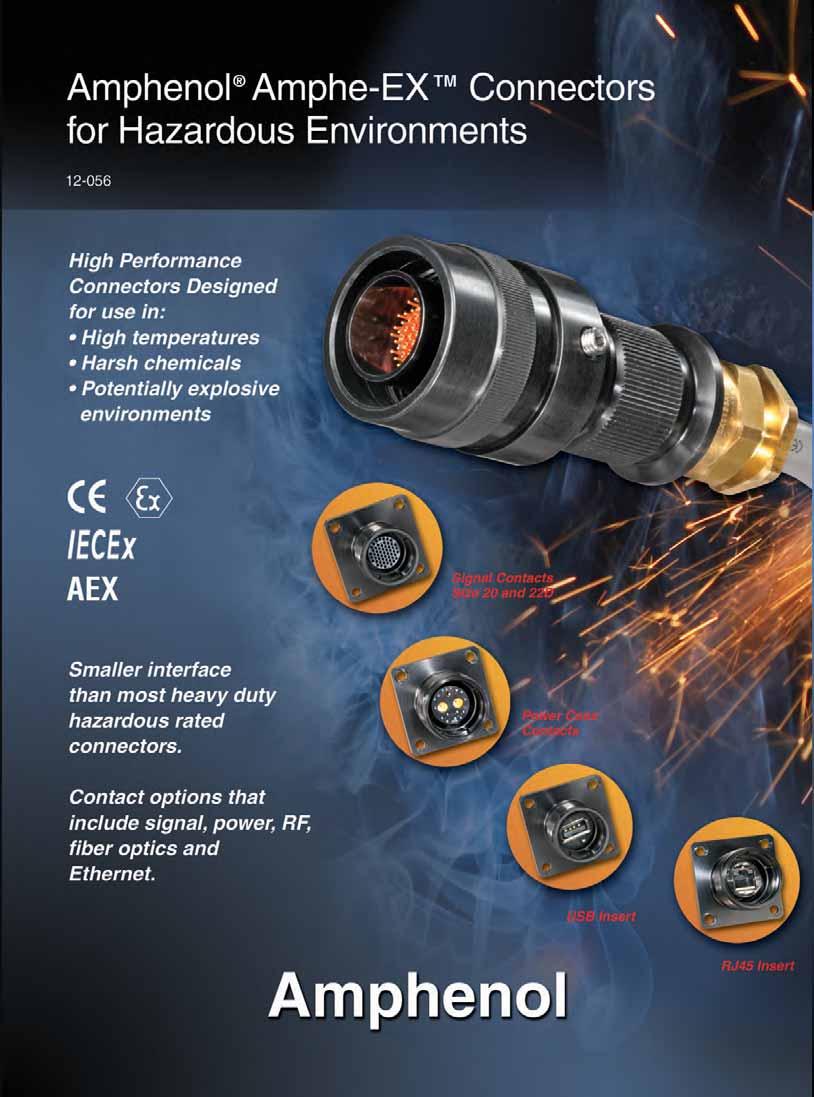
4 TM Series Hazardous Rated onnectors; smaller size and more contact options MPHE-EX FIRE OPTI HYRI ONNETOR INTROUTION With the ever growing need for more power and signal in a smaller interface in TEX rated areas, mphenol is pleased to introduce the mphe-ex circular connector series. mphe-ex Shell Styles esigned for Hazardous Environments MPHE-EX onnector Series is designed for use in TEX and IEex rated areas. MPHE-EX connectors are equipped to handle signal, power, RF or fiber optic requirements in the most harsh environments. MPHE-EX connectors offer a complete array of insert patterns, ranging from 2 # 20 contacts, right up through 79 # 22 contacts, and everything in between. In addition, MPHE-EX is able to provide both RJ45 and US connections into an TEX and IEex approved interconnect solution. hemical Manufacturing, Pharmaceutical Manufacturing, Petrochemical Refineries, Land and Offshore rilling Platforms are just a few of the areas that the new MPHE-EX Series will provide increased performance. MPHE-EX connectors are made from machined aluminum components, and plated in a hard anodic coating designed to withstand the most extreme environments. ouble-lead acme threads allow for a self cleaning mating action that does not clog under adverse conditions of ice, snow, mud or sand. The specific materials and design features of the MPHE-EX series were originally selected to satisfy the stringent requirements of the Military and erospace industries. These connectors combine electrical and mechanical capabilities that equal or exceed many of the parameters established by the Military specification MIL mphenol Industrial, one of the leading interconnect suppliers to Industrial markets around the world, welcomes this new product to it s current offering of harsh environment interconnect solutions. RJ45 inserts in-line receptacle box mount receptacle straight plug US inserts 1
5 TM Series performance criteria, specifications mphenol mphe-ex connectors TEX ertified for Zone 1-IIc hazardous environment. ert. # SIR 07TEX1229X IEEx and EX ertified enelec IP68 Rated Listed under EEx d IIc T6 Plugs and receptacles listed under EEx de IIc T6 HIGH TENSILE STRENGTH LUMINUM: ar Stock components precision machined, with points of impact designed for extra strength. HR NOI PLTING: ll machined aluminum parts are finished with a hard, scratch resistant coating per Mil--8625, Type III. ESILY ESSILE WIRE TERMINLS: onductors are readily terminated to contacts. able housings are slipped over conductors after terminating. umbersome handling and seating of inserts with conductors attached is eliminated. LRGE WIRE SPING: mple wire space is provided in cable housings and hardware. LE OPTIONS: able Gland terminations available to allow variety of cable types including unarmored, armored and sheathed cable built to the IEEE-45, UL1309, IE, S, IN and JI standards. Flexible cables like SOOW-, W, G-G and LO constructions can also be used with the MPHE-EX series connectors. For able Gland information, ask for mphenol able Glands and ord Grips catalog # INSERT VRITIONS: broad variety of inserts are offered ranging from 2 # 20 awg, up to 100 # 22 awg contacts. Numerous hybrid inserts available that offer combination copper and oax/twinax. In addition, Fiber Optic, RF45 and US options available. RoHS OMPLINT PROUT VILLE: onsult mphenol Industrial Operations Test urrent * When using silver plated wire. ONTT RTING Maximum Millivolt rop rimp* rimp Well ata ontact rimp Hermetic Well iameter ± ± ± ± (Power) 33 N ± Nominal Well epth SERVIE RTING Service Rating Suggested Operating Voltage (Sea Level) Test Voltage (Sea Level) (RMS) M VRMS N VRMS I VRMS II VRMS ** Please note that the establishment of electrical factors is left entirely in the designers hands, since he is in the best position to know what voltage, switching surges, transients, etc. can be expected in a particular circuit. 2
6 how to order TM Series mphenol mphe-ex series onnectors can be ordered by coded part number. Ordering procedure is illustrated by part number EXM P01 as shown below: onnector Series Material onnector Style Shell Insert rrangement ontact Type able Gland lternate Positions Special eviations EXM P 01 ( ) onnector Series EXM..designates mphe-ex Series Material.....designates luminum lloy lack Hardcoat S.....designates Stainless Steel.....designates rass onnector Style designates Plug with EX able Gland designates Panel Mounting Receptacle designates Inline Receptacle with EX able Gland Shell 9 thru 21 available Insert rrangement See insert arrangement chart, page 7. See insert configurations illustrated on page 8. ontact Type P.....designates standard 500 cycle pin contacts S.....designates standard 500 cycle socket contacts able Gland See chart page 11 for appropriate cable O.. lternate Positions Rotation of minor keys. See page 9. N not required for normal position. Specials eviations Position available for future planned special customer requirements ESSORY PS OE LOGI EXM- P- 9 onnector Series ap Style P - Plug ap R - Receptacle ap (see note below for material) ap 9-21 available (caps come standard on all assemblies) P-luminum Plug ap R-luminum Receptacle ap SP-Stainless Plug ap SR-Stainless Receptacle ap P-rass Plug ap R-rass Receptacle ap 3 RoHS OMPLINT PROUT VILLE - onsult mphenol Industrial Operations.

7 EXM-02 box mount receptacle EXM-02* 2.44 in. REF. 62mm REF. PTER 1.63 in. REF. 41.3mm REF..199 in. I. 5mm (4 Places) THRE * To complete order number see how to order on page 3. ssembly includes metal protective cover and lanyard. Shell Flange imension Mounting imension Inches Thread dapter NPT Type NPT NPT NPT NPT NPT NPT NPT Shell Flange imension ll dimensions for reference only. Mounting imension Millimeters Thread dapter Metric M M M M M M M40 4

8 EXM-01 in-line receptacle EXM-01* 4.56 in. REF. 116mm REF in. REF. EPENENT 62mm REF. ON EMPLOYE GLN.199 in. I. 5mm (4 Places) * To complete order number see how to order on page 3. ssembly includes metal protective cover and lanyard. ssembly also includes gland of choice; see page 11. Shell Flange imension Inches Mounting imension Shell Flange imension ll dimensions for reference only. Millimeters Mounting imension

9 EXM-06 straight plug EXM-06* EPENENT ON EMPLOYE GLN 4.21 in. REF. 107mm REF in. REF. 62mm REF. I. F THRE * To complete order number see how to order on page 3. ssembly includes metal protective cover and lanyard. ssembly also includes gland of choice; see page 11. Shell iameter ± Inches Shell iameter ± ll dimensions for reference only. Millimeters F Metric able Gland Entry Thread M16X1.5mm M16X1.5mm M20X1.5mm M25X1.5mm M25X1.5mm M32X1.5mm M32X1.5mm 6
10 insert availability and identification, contacts, sealing plugs Shell /rrg. Service Rating Total ontacts ontact (oax) 10 (Power) 8 (oax) 8 (Twinax) 9-35 M I I M I I I, Fiber Optic 4 2* M I I I M I M M N I M M M M I M 4 (See Note) Ground plane proprietary option available. rrg. 9-5 is exclusively ground plane type. See page 24 for further information of ground plane connectors. * Two size 16 contacts dedicated to fiber optics. onsult mphenol, Sidney, NY or catalog for fiber optic information. For RG180/U and RG195/U cables only. (ontact mphenol, Sidney, NY for other cable application). 8 oax and Twinax are interchangeable. ontact STNR ONTTS N SELING PLUGS FOR MPHE-EX SERIES ONTTS Pin Part Number Socket Part Number ontact SELING PLUGS Proprietary No. 8 (oax) (oax) (Twinax) (Twinax) T P 10 (Power) (Power) bove part numbers include standard 500 cycle finish designation - gold plating over suitable underplate in accordance with MIL For other contact options available for use in mphe-ex connectors, (thermocouple) consult mphenol, Sidney, NY. 7
11 insert arrangements front face of pin inserts illustrated F E G H G K J F E Insert rrangement Service Rating M I I M I I I, Fiber Optic M I Number of ontact ontact edicated to Fiber Optics L K M J H R N P G E F M L N P K U V R J T S H E G F H J G K L M F E Insert rrangement Service Rating I I M I M M Number of ontacts ontact Twinax R P S T a U b N Z c V M E Y W L X G F K J H V f W U Insert rrangement Service Rating oax I M M M Number of ontacts ontact 12 oax 8 oax oax h S N R K M E g V W U 31 j X 51 Y T i k s Z m E S h t r a n F R 71 g q p b 61 c G P f d 41 e N H 11 M J L K Insert rrangement Service Rating M I M Number of ontacts ontact oax 8 ONTT LEGEN
12 standard insert alternate positioning Shell MSTER KEY/KEYWY POSITION Key & keyway arrangement identification letter R or P S R or P S R or P S R or P S plug with a given rotation letter will mate with a receptacle with the same rotation letter. The angles for a given connector are the same whether it contains pins or sockets. Inserts are not rotated in conjunction with the master key/keyway. 9 11, 13, and 15 N N R S R S MIN KEYWY REEPTLE (front face shown) 17 and 19 N R S R S 21, 23, and 25 N PLUG (front face shown) MIN KEYWY P S P S P S P S 9

13 with RJ45 inserts and US inserts In addition to a complete line of power and signal inserts, the mphe-ex also offers RJ45 ethernet and US connection systems. The mphe-ex RJ45 and US assemblies offer all the same performance characteristics as the standard mphe-ex hardware. pplications include: ata acquisition and transmission Process control ommunication systems Embedded computers Other applications where Zone or lass rated connectors are required The mphe-ex with US allows the user to insert a standard US 2.0 cordset into the mphe-ex connector sets which will provide a flame-proof protection system. Part No: EXM USM The mphe-ex with RJ45 allows you to use an Ethernet lass 5/ at. 5e connection for 10ase T, 100 asetx or 1000 aset networks in hazardous environments. With the patented RJStop system, you can use the standard RJ45 cordset in our mphe-ex connector sets which will provide a flame-proof protection system. Part No: EXM RJSM 10
.3307 (8.4).1339 (3.4).3307 (8.4).3543 (9.0).5315 (13.5).2638 (6.7).4055 (10.3) 2.2835 (7.2).4606 (11.7).2835 (7.2).4606 (11.7).4528 (11.5).6299 (16.0).3701 (9.4).4921 (12.5).3780 (9.6).")
.7677 (19.5) 1.035 (26.3) 1.051 (26.7) 1.339 (34.0).9134 (23.2) 1.201 (30.5) mphenol offers an extensive line of explosion proof and general duty cable glands.")
14 cable glands EEx d able Gland ode Unarmored able No deviation if Unarmored rmored & Sheathed able -S rmored & Sheathed with reduced bore -SR U Standard O-Reduced MIn Max MIn Max MIn Max MIn Max (4.0).3307 (8.4).1339 (3.4).3307 (8.4).3543 (9.0).5315 (13.5).2638 (6.7).4055 (10.3) (7.2).4606 (11.7).2835 (7.2).4606 (11.7).4528 (11.5).6299 (16.0).3701 (9.4).4921 (12.5).3780 (9.6).5512 (14.0).3701 (9.4).5512 (14.0).6102 (15.5).8307 (21.1).4724 (12.0).6929 (17.6).5315 (13.5).7874 (20.0).5315 (13.5).7874 (20.0).7992 (20.3) (27.4).6614 (16.8).9409 (23.9).7677 (19.5) (26.3).7677 (19.5) (26.3) (26.7) (34.0).9134 (23.2) (30.5) mphenol offers an extensive line of explosion proof and general duty cable glands. onsult mphenol Industrial Operations and ask for new catalog , mphenol able Glands and ord Grips. Fiber Optic ustom able ssembly esign and Fabrication mphenol s cable assembly expertise dates back to the first industry standard fiber optic connector, over 25 years ago. Our depth of understanding of connector and termini design, and the complete control of connector materials, make mphenol Fiber Optic cable assemblies one of the best in the industry. mphenol offers a comprehensive line of single mode and multi-mode cable assemblies in a variety of cable configurations. From simplex jumpers to multi-fiber custom assemblies, mphenol can design and supply all of your cable needs. High quality polishing processes have been developed to meet and exceed industry standard specifications for insertion loss, return loss and endface geometry. ll assemblies are designed to intermateability standards for optical and physical performance criteria. mphenol can assemble, polish and test many harsh environment and commercial grade connectors including: MIL-PRF standard MT/MP0 (for availability, consult mphenol Industrial) onnector and cable materials are extensively inspected prior to assembly. Every completed cable assembly receives 100% inspection for both insertion loss and visual defects. Interferometers are used for accurate endface geometry testing. You specify the optical and mechanical requirements of the cable assembly and mphenol s fiber optic application s engineers will develop an end-to-end interconnect solution. esign creativity, experience and an understanding of harsh environments will ensure a functional and manufacturable design. 11
15 fiber optic termini MIL-PRF-29504/4 & /5 multi-mode, size 16 mphenol Multi-mode, 16 Termini Features: Precision ceramic ferrules which precisely position the fiber within the termini. Precision ceramic alignment sleeves insure accurate fiber to fiber alignment. Socket has threaded protective shroud with anti-rotation key, manufactured from rugged PEEK TM material, provides protection for the ceramic alignment sleeve. Stainless steel termini bodies and springs. Laser welded components for stronger construction. llows for multiple fiber accommodations Order multi-mode termini by mphenol part number designation or MIL-PRF designation as shown in the charts below. onsult mphenol, Sidney, NY for further availability. 16 Multi-mode Pin Terminus I. REF MX.* ERMI FERRULE.525 REF..080 MX. LE I ± I ±.001 I. TERMINUS STRENGTH MEMER SHRINK TUE.040 MX. UFFER LE I. 16 Multi-mode Socket Terminus.080 MX LE I..525 REF ± MX*.537 ± I MX UFFER LE I. SHRINK TUE STRENGTH MEMER TERMINUS ±.0002 I. ERMI FERRULE I. REF. SHROU LIGNMENT SLEEVE** * Indicated dimension when fully assembled. ** lignment sleeve shipped unassembled. mphenol Part Number F F Fiber Optic Pins Ordering Information Fiber ore/ladding 50/125 & 62.5/ /125 & 62.5/ 125 ia. Ref. (Microns) Ferrule Hole Tolerance Reference Only M29504/4*-XXXX , 0 M29504/ , 0 F /125 & 62.5/ 125 F / , 0 superseded by MIL-PRF , 0 M29504/ superseded by MIL-PRF F / , 0 M29504/ F /140/172 (Polyimide) , 0 F /140/172 (Polyimide) F / , 0 superseded by MIL-PRF , 0 M29504/ superseded by MIL-PRF F / , 0 M29504/ mphenol Part Number F F Fiber Optic Sockets Ordering Information Fiber ore/ladding 50/125 & 62.5/ /125 & 62.5/ 125 ia. Ref. (Microns) Ferrule Hole Tolerance Reference Only M29504/5*-XXXX , 0 M29504/ , 0 F /125 & 62.5/ 125 F / , 0 superseded by MIL-PRF , 0 M29504/ superseded by MIL-PRF F / , 0 M29504/ F /140/172 (Polyimide) , 0 F /140/172 (Polyimide) F / , 0 superseded by MIL-PRF , 0 M29504/ superseded by MIL-PRF F / , 0 M29504/ * onsult mphenol erospace, Sidney NY for qualification status. dditional fiber optic termini sizes available upon request; consult mphenol erospace for availability. 12
16 fiber optic termini multi-mode, size 20 mphenol Multi-mode, 20 Termini Features: Offers increased termini density esigned with similar high performance components as the proven size 16 termini Maintains fiber optic/electrical hybrid capabilities llows for multiple fiber accommodations Termination accomplished using the industry proven epoxy/polish method. an be polished ir Gap (G) or Physical contact (P). Order multi-mode termini by mphenol part number designation as shown in the chart below. onsult mphenol, Sidney, NY for further availability. 20 Multi-mode Pin Terminus.069 ±.001 I. I. REF. ERMI FERRULE MX.*.063 MX. LE I I STRENGTH MEMER SHRINK TUE.037 MX UFFER LE I. 20 Multi-mode Socket Terminus.123 MIN ±.020 STRENGTH MEMER MX.*.162 ± I. LIGNMENT SLEEVE**.063 MX. LE I..037 MX. UFFER LE I. SHRINK TUE.069 ±.001 I. ERMI FERRULE I. REF.263 ±.004 * Indicated dimension when fully assembled. ** lignment sleeve shipped unassembled. Fiber ore/ladding ia (Microns) Ordering Information Multi-mode Termini ( 20) for MIL-TL onnectors mphenol Part Numbers ia Ref Ferrule Hole Tolerance 20 Socket 20 Pin Inches Microns 50/ /125 F F , 0 100/140 F F , 0 dditional sizes available upon request: consult Sidney, NY for availability. 13
17 application tools The following data includes information pertaining to the application tools which have been established for crimping, inserting, and removing contacts incorporated in the mphe-lite Series connectors. For additional information on coaxial contact tools see catalog ll crimping tools included are the full cycling type. There is a possibility of additional crimping tools other than those included being available at present or in the future for this specific application. REOMMENE RIMPING TOOLS ontact /Type rimping Tool Turret ie or Positioner 12 Pin and Socket M22520/1-01 M22520/ Pin and Socket 20 Pin and Socket 22 Pin 22 Socket 8 Twinax enter Pin and Socket 8 Twinax Intermediate Outer Pin & Socket M22520/1-01 M22520/7-01 M22520/1-01 M22520/2-01 M22520/7-01 M22520/2-01 M22520/7-01 M22520/2-01 M22520/7-01 M22520/2-01 M22520/5-01 M22520/1-04 M22520/7-04 M22520/1-04 M22520/2-10 M22520/7-08 M22520/2-09 M22520/7-07 M22520/2-07 M22520/7-05 M22520/2-37 M22520/5-200 Where 2 or 3 tools are listed for a contact size, only one tool and its die or positioner are required to crimp the contact. The above crimping tools and positioners are available from the approved tool manufacturer. ontact /Type 8 oaxial Inner Pin and Socket 8 oaxial Outer Pin and Socket rimping Tool M22520/2-01 M22520/5-01 M22520/5-01 M22520/10-01 Turret ie or Positioner M22520/2-31 M22520/5-05 ie losure M22520/5-41 ie losure M22520/10-07 ie losure 16 oaxial Inner Pin and Socket M22520/2-01 M22520/ oaxial Outer Pin and Socket M22520/4-01 M22520/ oaxial Inner Pin and Socket M22520/2-01 M22520/ oaxial Outer Pin and Socket M22520/31-01 M22520/ (Power) TP P-1 Use with ontact MS Part Number Plastic Tools olor INSERTION TOOLS MS Part Number ngle Type 14 Metal Tools Proprietary Part Number Straight Type Proprietary Part Number 10 (Power) M81969/14-05* Gray / (White) M81969/8-11 Green 12 M81969/14-04* Yellow / (White) M81969/ Yellow 16 M81969/14-03* lue / (White) M81969/ lue 20 M81969/14-10* Red / (Orange) M81969/ Red 22/22 N/ N/ N/ N/ TP rown 22 M81969/14-01* Green / (White) M81969/ lack 8 oaxial None Required 8 Twinax None M81969/46-06** None Red Plastic Tools REMOVL TOOLS Metal Tools For Unwired ngle Type Use with ontact MS Part Number olor ontacts Proprietary Part Number MS Part Number Proprietary Part Number Straight Type Proprietary Part Number olor 10 (Power) M81969/14-05* (Gray) / White M81969/8-12 Green / White 12 M81969/14-04* (Yellow) / White M81969/ Yellow / White 16 M81969/14-03* (lue) / White M81969/ lue / White 20 M81969/14-10* (Orange)/ Red M81969/ Red / White 22 M81969/14-01* (Green) / White M81969/ Green / White 8 oaxial M81969/14-12 Green None None RK264-8 N/ 8 Twinax M81969/14-12 Green None M81969/46-12** N/ N/ The M81969/8, , ,and metal contact insertion and removal tools will accommodate wires having the maximum outside diameter as follows: ontact size , , , When wire diameters exceed those specified, the plastic tools must be used. * ouble end insertion/removal tool. ** Twinax insertion tools are available only in a straight type, metal version. olor To be determined. ontact aniels Manufacturing o. for availability.
18 assembly instructions L Read manufacturer s assembly instructions before actually starting to assemble connectors. esides the matter of instruction on correct procedures, there are two important reasons for this preliminary step: To identify the various component parts, and to check for any missing parts. 2. ut cable jacket and sheathing squarely and sheathing squarely and to correct length, using only wire strippers that have been approved for the operation. In preparing the individual wires in cables and harnesses for assembly, make allowances in length for reaching the outer most circle of contacts cavities in the conductors. The insulation should be cut progressively longer as they extend out from the center of the cable or harness to assure sufficient length. 3. Follow Table 1 Figure 1 covering maximum cable stripping lengths for effective cable gland sealing. ll conductors should be fit into contact wire wells correctly. practice layout should be done so that an assembler can oversee what the finished termination will look like. 4. efore starting actual termination of wires, it is essential that cables and harnesses be laid out in a specific order in accordance with the wiring diagram. Proper layout will eliminate the need for twisting and crossover of conductors. If the wiring layout is not correct, the termination operation will be difficult or even impossible and the chances for making errors will be increased. able and harness assemblies having a spiral layout must also be matched carefully to the correct contacts in both the male and female inserts. 5. Some cables that will be used will have a basket weave type of armor under the outer jacket (sheath) and over the inner jacket. Since many regulatory entities require that the armor be grounded at least at the source end, it is beneficial to ground the armor via a spare contact within the connector. Follow the removal of sufficient amount of outer jacket (see Table 1) ample amount of armor can be clipped away, but not all. n adequate amount should remain in order that a small cross-section conductor, short in length, be woven into the remaining armor weave and either soldered or covered with mastic impregnated heat shrink, creating an intimate bond to the armor. t the opposite end of the short piece of wire a contact should be crimped and inserted into the insert. 6. Use only correctly sized and provided Exd glands to assure resistance to moisture and other contaminates. 7. Use only the proper crimping tools that have been set or calibrated with precision gages. 8. Make certain that all contacts are the correct size before attempting to assemble in insert cavities. This point is particularly important when both power and control types of contacts are used in the same connector. 9. e sure that ground contacts are correctly located. 10. Seat all contacts properly so that they will not be damaged or become disengaged during connector mating operation. 11. Use only the proper insertion tools and be sure that they are aligned axially when pushing contact into their fully seated position. 12. When inserts have more cavities than the conductors, plug unused cavities with furnished contacts. 13. fter all terminated contacts are inserted in their respective cavities and inspected, the cable adapter or insert clamp nut should be tightened with a wrench. This assembly operation should be done by placing the components in a vise with smooth-faced jaws and using a strap wrench. 14. When handling cables, use adequate support to prevent damage to the internal wires. Exd glands are intended for sealing purposes and should not be used as a cable grip. 15. If for any reason, terminated conductors have to be removed from an insert because of an assembly error or change in circuitry, be sure to remove the cable gland or cable adapter first before extracting the contact and reinserting it. 16. If one of the connector poles is a ground wire, make sure that it is grounded properly before the connector actually is engaged. 17. When connectors have the same configuration are to be mounted closer together, different or alternate key arrangements should be used to prevent mismatching and possible damage to the electrical system. 18. lways inspect all aspects of connector assembly operations before putting connector into actual operation. 19. rimping and terminating of conductors to contacts must be done carefully. Make certain that all wire strands are fully bottomed in contact wells by checking through inspection hole provided. 15
19 assembly instructions 20. Never try to straighten bent contacts. Straightening cannot be done properly and the plating on contacts very likely will be marred. This will result in a high resistance connection and will expose the base material to possible corrosion. 21. lose review should be made of the mixing instructions that follow. Potting of the connector where required should be the very last step the assembler does prior to fastening down the grommet and nut on the cable adapter. Ringing out of the contacts with their mate should be done prior to potting. 22. It is recommended that all receptacles be potted while coupled to their mating connector. 23. Each assembly operator should be his own inspector. Worn, damaged, or defective tools should be reported immediately to foreman and supervisors. ssembly operators should be indoctrinated with this attitude and made to understand the importance of always guarding quality. ssembly workmanship is significant factor in terminating the quality of multiple contact connectors. Quality cannot be inspected into connectors; it must be built-in during each and every assembly operation. The following instructions apply to equipment covered by certificate number: SIR 07TEX1229X The equipment may be used with flammable gases and vapors with apparatus group(s) II,II, & II and with temperature classes T6, T5, T4, T3, T2 & T1. The equipment is only certified for use in ambient temperatures in the range -20 to +40 and should not be used outside this range. The product compliances with the following standards: EN :2006 General requirements for electrical apparatus for explosive gas atmospheres EN :2007 EN :2003 EN :2006 EN :2004 Electrical apparatus for explosive gas atmospheres - Part 1: Flameproof enclosures "d" (Plus or 1)(IE :2003) Electrical apparatus for explosive gas atmospheres - Part 7: Increased safety "e" (IE :2001) General requirements for electrical apparatus for use in the presence of combustible dust Electrical apparatus for use in the presence of combustible dust. Protection by enclosures t Installation shall be carried out by suitably-trained personnel in accordance with the applicable code of practice e.g. EN It is the end user s responsibility to ensure that the product, as specified and confirmed by the product label, is suitable for it s intended application. Inspection and maintenance of this equipment shall be carried out by suitably trained personnel in accordance with the applicable code of practice e.g. EN Repair of this equipment shall be carried out by suitably trained personnel in accordance with the applicable code of practice e.g. EN
20 assembly instructions The certification of this equipment relies upon the following materials used in its construction: onnector Material: STM 211 or T6 luminum O-ring Seal Material: una Rubber w/ urometer of 70 SHORE Potting ompound: Hysol Epoxy Resin Part # ES4412 If the equipment is likely to come into contact with aggressive substances, then it is the responsibility of the user to take suitable precautions that prevent it from being adversely affected, thus ensuring that the type of protection provided by the equipment is not compromised. ggressive substances: e.g. acidic liquids or gases that may attack metals, or solvents that may affect polymeric materials. Suitable precautions: e.g. regular checks as part of routine inspections or establishing from the material s data sheets that it is resistant to specific chemicals. ontact Preparation Instructions rimp Tools: M22520 Series is recommended. See Tool Table for choice of turret head and selection setting according to contact size, part number and wire gage size. Setting Up and Operation: onsult Tool Manufacturer Wire Preparation and rimping Strip wire to required length. (See Figure 1). When using hot wire stripping do not wipe melted insulation material on wire strands; with mechanical strippers do no cut or nick strands. See Table 1 for proper finished outside wire dimensions. Figure 1 SIZE 22, 22M, 22 1/8 INH 5/32 INH SPEIL ONITIONS FOR SFE USE: The X suffix to the certificate number relates to the following special conditions(s) for safe use: 1. The plugs and receptacles shall only be used with suitable certified cable glands capable of a temperature range at their point of mounting between -20 to ables fitted to the plugs and receptacles shell be suitable for continuous operating temperature of at least Plugs are not permitted to remain energized when not engaged to the receptacles as per EN ; clause The plugs and receptacles are not to be energized when fitted with the environmental blanking caps. 5. n explosion proof receptacle cap must be fitted to the receptacles to be re-energized when they are not mated to a plug. 6. The connector does not incorporate an external earth facility. It is the responsibility of the user or installer to ensure adequate internal earth continuity by means of terminating ground wire to spare contact within the insert patterns for both plug and receptacles to allow for continuity. 7. The panel mount receptacles shall only be used where the temperature at the point of entry in service on the associated enclosure is between -20 to SIZE 12, 16, 20 7/32 INH 1/4 INH Table 1: onductor iameters ontact Wire iameters (in.) ** Min. Max M, **Min. diameters to insure moisture proof assembly; max diameters to permit use of metal removal tools. Twist Strands together to form a form bundle. Insert stripped wire into contact applying slight pressure until wire insulation butts against wire well. heck inspection hole to see that wire strands are visible. If there are strayed wire strands, entire wire end should be re-twisted. Insert wire and contact into crimping tool as far as possible. rimp contact wire well. 17
21 assembly instructions ontact Insertion and Removal When inserting or removing contacts, first remove securing devices and slide devices over wires in proper sequence onsult page 14 for correct insertion or removal tool (metal or plastic) according to contact size Insertion: Slip correct size tool (with plastic tool, use colored end) over wire insulation and slide forward until tool bottoms against rear contact shoulder. ontact must be aligned with grommet hole and not inserted at an angle. Push forward until contact is felt to snap into position within insert. Remove tool, holding forward on the wire in order to prevent contact from being dragged back with tool. Gently pull each wire to ensure contact is properly seated. Uncrimped ontacts and Sealing Plugs: Fill in unused holes with an uncrimped contact. Follow with a teflon sealing plug, small diameter first, so that one end protrudes out the rear of grommet. See Table 2 for sealing plug application data. (Optional insertion of large end first is possible, but not recommended). Table 2: Sealing Plugs ontact olor ode MS Part Number 10 Green M85049/ Yellow MS lue MS Red MS , 22M, 22 lack MS Slide securing devices forward and tighten using connector pliers. onnector holding tools are recommended while tightening back accessories. UTION: WHEN INSERTING OR REMOVING ONTTS, O NOT SPRE OR ROTTE TOOL TIPS. Removal: Slip correct sized tool (with plastic tool, use white end) over wire insulation and slide forward on wire until tool tip enters rear grommet and comes to a positive stop on contact shoulder. Grip wire, and simultaneously remove tool, contact and wire. (On occasion, it may be necessary to remove tool, rotate 90 and reinsert). Tools: Using applicable removal tool, insert and carefully work tool tips over wire well. When tips bottom, contact will release from internal retention clip. Push contact from connector front face out connector rear with round ended non-metallic rod. Rod will follow contact. (See page 14 for applicable removal tool and correct rod diameter). Unwired Removal Tool ( XX): Removal procedure is same as with standard tools with the exception that tool will withdraw contact without pushing from front. Push plunger to remove contact from tool. (See page 15). onnector ssembly Instructions ssembling an Inline Plug and Inline Receptacle onnectors 1. Slide the EX gland onto the cable about 12, threaded end last. 2. Slide the able dapter onto the cable, up to the EX Gland, large diameter first. 3. Slide the oupling nut onto the cable, up to the able dapter, Grub Screw end first. 4. Group all conductors according to size to facilitate orderly termination. 5. Working on one conductor at a time, strip the insulation off per the wire stripping length given in Figure 1 and terminate a contact to it, using a properly adjusted crimp tool, following crimp instruction found in section II of ontact Preparation Instructions. Repeat the process for each conductor. 6. Make sure the Grub Screws are fully retracted, then slide the oupling Nut up onto the plug shell, until seated against it s mating shoulder. 7. Thread the able dapter onto the plug shell, and hand tighten. 8. Thread the EX Gland onto the able adapter, and hand tighten. 9. Using a strap wrench, fully tighten the cable adapter onto the plug shell. 10. Position the cable correctly. Using a hex wrench, tighten the EX Gland The seal must grip the outer jacket of the cable when the cable gland is tightened. Tighten ack Nut (or onduit Receptor) to Entry ody. Ensure seal makes full contact with cable sheath. Tighten an extra 1½ turns (up to 2½ turns for minimum cable). Unwired ontacts: Remove sealing plugs. Standard Removal 18
22 assembly instructions Preparing a ulkhead Receptacle onnector for Enclosure Mounting. ll receptacle shells have, contained within them, contact positioning inserts that are permanently installed by the factory. 1. Slide the ulkhead dapter up onto the cable, or conductor group; knurled end first. 2. Terminate each conductor with it s proper contact. 3. Populate the insert with contacts by poking each of the wired contacts into it s respective insert cavity, following an electrical schematic for the system you are wiring. 4. Slide the bulkhead adapter back down the conductors, and screw it onto the panel mount receptacle. 5. Use a strap wrench to tighten the bulkhead adapter until fully tightened to shoulder. 6. Referring to mphe-ex potting instructions, stand the assembly vertical, conductors pointing up, and fill the adapter with cement to a level 1/16 below the top of the adapter. fter curing, this assembly is now permanently cemented, non-separable and non-repairable, and can be mounted to the bulkhead. 7. It is best to fit the connector to the bulkhead at a time when the free end of the cable is not terminated to the electrical system. If this is not possible, then it is necessary to rotate the connector assembly counter-clockwise to wind the cable/ conductors so that when the assembly is threaded into a bulkhead in the subsequent instruction, the cable/conductors regain their most natural lay, once the connector is mounted to the bulkhead. (Rotations required to be determined by end-user). 8. Thread the receptacle assembly into the bulkhead until the seal touches down, then tighten it by the smallest fraction of a revolution to the first instance that the mounting holes line up with the threaded enclosure holes. 9. Position the protective covers lanyard tab over one of the mounting holes and screw a fastener through it. pply the remaining fasteners to the other three holes with torque suitable for screw size used. 10. Install the protective cover and tighten fully. 11. Secure both grub screws to prevent unauthorized removal. ll cable adapters, other than ones suited for mating with an EXcertified gland, must be filled with encapsulant (potted). The material certified for use in filling this connector line is exter- Hysol Product #ES4412. The user or installer shall consider the performance of these materials with regard to attack by aggressive substances that may be present in the hazardous area. This material is a two-component casting system with a 1:1 volumetric mix ratio. It has low exothermic qualities, peak at only 102 F during cure in 2 hours at 140 F. The product is available in premeasured mix & dispense packaging. More information is available by contacting the following authorized suppliers: mphenol Industrial Operations elaware venue Sidney, New York US Phone (607) mphenol Industrial Operations Optimize Nogales 180 N Freeport rive Nogales, Z Phone: mphenol Technology Industrial Operations-Shenzhen LK 4 Fuan 2nd Industrial Park ayang Road Fuyong aoan Shenzhen hina Phone: ulkhead dapter ulkhead adapters should be filled to a maximum of 1/16 below the top of the adapter. are must be exercised so that the potting compound does not contaminate the bulkhead threads, or spill onto the outer surfaces of the receptacle flange. In preparation for potting, the receptacle is to be mated to it s corresponding plug, so that all contacts are mated and in their optimal post-potted position. When potting, the receptacle flange should be rigidly fixtured in a horizontal position. This fixture must be capable of holding the mated connector pair in that position for a minimum of 2 hours at room temperature. The exiting conductor/cable should be fixtured inline above the connector pair, during the entire curing process. MPHE-EX TM Potting Instructions 19
23 assembly instructions Mixing/Potting Instructions 1. UTION: Wear goggles or other eye protection during all operations. 2. The potting compound is premeasured in burst bag packaging. This packaging consists of a single plastic bag that is compartmentalized into two chambers, each containing one part of the two part compound. The segregating feature is called a burst seal. 3. Lay the bag on a flat surface. hoosing either end of the bag that is parallel to the burst seal, start coiling/rolling the bag so that the compound in that half of the bag is pushed up against the burst seal. 4. Squeeze and apply pressure to the rolled side of the bag so that the compound bursts through the burst seal and joins the compound on the other side of the bag. Unroll the bag. 5. Mix the entire contents of the bag, by alternately squeezing the bag, and working the bag across the edge of a table, to fully move the entire contents of the bag, back and forth, between chambers. Work the material in this manner, constantly, for a minimum of 4 minutes. 6. Once mixed, squeeze all the contents away from one corner of the bag. fully clearing that corner of the bag of all compound. 7. Make a 3/16 pouring spout by snipping off the bags cleared corner. 8. To minimize air entrapment, slowly pour the compound into the back end of the bulkhead adapter, to a level shown in Figure Z. 9. Set the bag containing the remaining compound aside, so that it may cure. fter cure, the bag may be disposed of safely, along with common consumer refuse. UTION: s the remaining compound cures, the bag will become hot. SIR Product Labeling Information Information below must be attached to connectors via nonremovable label. mphenol Industrial Sidney NY US Part Number, Ref Work Order Number; ate ode 0518 II 2 G EEx dii T6 / Ex t 21 IP68 (Plug and Receptacles) EEx de II T6 / Ex t 21 IP68 (Panel mount receptacles filled with cement) Sira 07TEX1229X max volts, max amp. urrent rating per pin o not separate when energized o not open when an explosive gas or dust atmosphere is present Hysol Volume Per ulkhead dapter Shell Fill Length Inside dapter (inches) dapter iameter (inches) Internal Volume (in ^ 2) Internal Volume (ounces) Note: This is the maximum volume of cement needed, without considering volume claimed by the conductors 20
Amphenol Aerospace. Accessories Contact Terminating Tools For MIL-DTL Connectors III HD Dualok II I SJT Accessories Aquacon Herm/Seal PCB
 ccessories ontact Terminating Tools For ML-TL- onnectors mphenol erospace ontact nsertion Tools ontact mphenol/ nsertion Tool Mil. olor ode nsertion Tool Replacement Tip & Pin mphenol/ Mil. 20 ZZL-R-9510--20
Amphenol Star-line Ex Assembly Instructions (applies to ATEX and IECEx product)
") Amphenol Star-line Ex Assembly Instructions (applies to ATEX and IECEx product) L-2120-3 Document Contents: Familiarization & Assembly Information Contact Assembly & Termination Mixing Instructions Potting
Amphenol Star-line Ex Assembly Instructions (applies to ATEX and IECEx product) L-2120-3 Document Contents: Familiarization & Assembly Information Contact Assembly & Termination Mixing Instructions Potting
MIL-C-5015 Bulkhead Receptacles
 I5015 ulkhead eceptacles F/TF How to Order TF and F pressurized bulkhead receptacles mate with standard S type plugs (3106,3107 and 310) if contact arrangements correspond. oth the F and TF have resilient
Amphenol. Amphenol GT Series Reverse Bayonet Coupling Connectors. Ruggedized Connector Series for Rail/Mass Transit and other Harsh Environments
 mphenol eries everse ayonet oupling onnectors 12-024-8 uggedized onnector eries for ail/ass ransit and other arsh nvironments mphenol able of ontents age o. mphenol eries eversed ayonet oupling onnectors
TABLE OF CONTENTS. Amphenol Aerospace is a Certified ISO 9001 Manufacturer.
 This catalog covers the Amphenol /Matrix MIL-C- 83723, Series III Connectors. These connectors incorporate crimp rear release contacts. There is great diversity within this cylindrical family, with the
2M Series Contacts and Tools
 Crimp Type AMPS #23 #20HD #20 #16 #12 AWG Part Number Color Band 1st 2nd 3rd #22-#28 2M809-001 N/A N/A N/A #26-#30 2M809-042* Blue N/A N/A 5 Socket #22-#28 2M809-002 N/A N/A N/A Socket #26-#30 2M809-043*
Low Mating Force how to order (military types)
") how to order (military types) M, D, P onnectors Military Part Ordering Procedure Example part number M55302/16610X1 is shown as follows: ody Type/ ontact Style Rows M55302 /166 10 X 1 ontacts per Row Tail
how to order (military types) M, D, P onnectors Military Part Ordering Procedure Example part number M55302/16610X1 is shown as follows: ody Type/ ontact Style Rows M55302 /166 10 X 1 ontacts per Row Tail
Features and Application
 ML-DTL- Features and Application MS2426*/AE66* Features and Application ML-DTL- family offers connectors with bayonet coupling as well as threaded coupling. These connectors are intermateable with correspondingly
Amphenol. Amphenol /Matrix MIL-C-83723, Series III Connectors. Bayonet, Threaded or Quick-Disconnect Coupling Connectors for Demanding Environments
 Amphenol /Matrix MIL-C-, Series III Connectors -0- Bayonet, Threaded or Quick-Disconnect Coupling Connectors for Demanding Environments Amphenol This catalog covers the Amphenol /Matrix MIL-C-, Series
Amphenol. Amphenol ACA-B Reverse Bayonet Coupling Connectors
 mphenol - everse ayonet oupling onnectors 12-027-1 he Industrial onnector for actory utomation, obotics, rocess ontrol and est & easurement quipment. mphenol able of ontents age o. mphenol - everse ayonet
Features and Application
 MIL-DTL-38999 Features and Application Series II Features and Application MIL-DTL-38999 Series II connectors feature a bayonet coupling mechanism with lower profile design and rear-removable crimp contact
17 TW SERIES. Hybrid Connector SPECIFICATIONS: MATERIALS AND PLATINGS ELECTRICAL DATA CLIMATIC DATA MECHANICAL DATA
 17 TW SERIES Hybrid onnector mphenol s 17TW series hybrid -Subminiature connectors are available with power, coax, high voltage and signal contacts assembled in the same connector body. These connectors
Amphenol. eries SJT. Series SJT. VG 96912, Series 1 PAN JN 1003
 Amphenol eries SJT Series SJT VG 96912, Series 1 PAN 6433-2 JN 1003 Ordering information Ordering example: SJT G 06 RT 14-35 P A 014 Series (p. 9, 15, 18) SJT Scoop proof (100% scoop-proof) Junior (Miniature
Table of Contents Introduction... 2 Amphenol MIL-DTL-5015 and MIL-5015 Type Standard Cylindrical Connectors General Information, Class
 able of ontents age Introduction...................................... 2 mphenol I--5015 and I-5015 ype tandard ylindrical onnectors eneral Information, lass esignations............................. 3
Amphenol. ACA-B and GT Series Reverse Bayonet Coupling Connectors.
 mphenol - and eries everse ayonet oupling onnectors www.amphenol-industrial.com mphenol 97 eries onnectors are U recognized and recognized. or further information on your individual application requirements,
MMC RTX series EN3716
 MMC RTX series EN3716 7 CONTENTS Page Introduction... 7-4 Application 7-4 Features... 7-4 Product overview... 7-5 Electrical characteristics... 7-6 Mechanical & environmental characteristics... 7-6 Products
Circular Connectors. Contents. Introduction Specifications Cable Connectors Panel Connectors Accessories
 ircular onnectors ontents Introduction Specifications able onnectors Panel onnectors ccessories ircular onnectors These connectors are designed for use in harsh environments. The high specification connectors
Application Specification Circular Plastic Connector (CPC) Series 45 System 05 AUG 14 Rev D
 Series 45 System 05 AUG 14 Rev D") Application Specification Circular Plastic Connector (CPC) 114-13137 Series 45 System 05 AUG 14 Rev D NOTE i All numerical values are in metric units [with U.S. customary units in brackets]. Dimensions
Application Specification Circular Plastic Connector (CPC) 114-13137 Series 45 System 05 AUG 14 Rev D NOTE i All numerical values are in metric units [with U.S. customary units in brackets]. Dimensions
Amphenol Heavy Duty Cylindrical Connectors
 mphenol Heavy Duty ylindrical onnectors 12-052-9 mphenol mphenol Heavy Duty ylindrical onnectors MIL--22992/Proprietary High urrent apacity Rugged onstruction Safety Serviceability mphenol meets the demands
Amphenol QWL Series Cylindrical Connectors Amphenol
 mphenol QW eries ylindrical onnectors 12-053-4 mphenol O O escription age escription... age mphenol eavy uty ylindrical onnectors QW eries... 2 QW the environmental connector... 3 QW how to order... 4,
Electrical Voltage rating Test Voltage (Vrms) service rating sea level at 21000m M N I II
 service rating sea level at 21000m M N I II") JVS ronze Series pplications Navy vessels - Military - Merchant fleet - Transportation - Oceanography - attle-field cables, shelters - Signalling - ield equipments Standards MIL- 38999 Series III 75 201.002
JVS ronze Series pplications Navy vessels - Military - Merchant fleet - Transportation - Oceanography - attle-field cables, shelters - Signalling - ield equipments Standards MIL- 38999 Series III 75 201.002
Amphenol 348 Series High Density Connectors
 348 Series High Density Connectors 12-093-6 348 Series I, II Table of Contents 348 Series Page No. High Density Connectors........................................................................ 1 Specifications.................................................................................
M300 Connectors Introduction
 ontents Introduction Specifications Mating Profiles Jackscrew mm Pitch High-Reliability onnectors Female P onnectors Female able onnectors Female able ssemblies Male P onnectors Male able onnectors Male
MIL-PRF QPL Connectors MIL-PRF QPL Adapters Online Catalog Volume 1
 MIL-PRF-39012 QPL onnectors MIL-PRF-55339 QPL dapters Online atalog Volume 1 Delta QPL connectors and adapters meet or exceed all requirements of MIL-PRF-39012 and MIL-PRF-55339. ecause these specifications
THREADED & BAYONET CONNECTORS FOR DEMANDING ENVIRONMENTS
 MILITARY AND COMMERCIAL AVIATION MIL - DTL - 83723 SERIES III THREADED & BAYONET CONNECTORS FOR DEMANDING ENVIRONMENTS CONNECTORS FOR DEMANDING ENVIRONMENTS THREADED AND BAYONET MILITARY AND COMMERCIAL
Amphenol /Matrix MS/Standard MIL-C-5015 Cylindrical Connectors
 Amphenol /Matrix MS/Standard MIL-C-5015 Cylindrical Connectors 12-026-2 Crimped Rear Release Qualified for Environmental and Firewall Applications Amphenol This catalog covers the Amphenol /Matrix MIL-C-
Heavy Duty Cylindrical MIL-C QWLD
 20 eavy uty ylindrical I--22992 QW mphenol eavy uty ylindrical onnectors I--22992, QW wall mount receptacle cable connecting plug box mount receptacle jam nut receptacle (wall mount) thru bulkhead receptacle
KDB / VG Series
 / V 9523 Series ontents Introduction........................... 2 onnector design...................... 2 Technical data......................... 3 ounting dimensions.................. 5 ow to order..........................
Amphenol Amphenol Pcd Terminal Junction Systems
 igh Quality Interconnect Products or Military and erospace pplications mphenol mphenol Pcd Terminal unction Systems Terminal unction Systems MIL-T-171 Series I lass MIL-T-171 Series I unction Modules QPL-approved
DT Family. DT Family Overview DTM SERIES OVERVIEW DT SERIES OVERVIEW DTP SERIES OVERVIEW
 T amily Overview UTSH T, TM, and TP series environmentally sealed connectors are designed for cable to cable and cable to board applications. The T connectors are used in harsh environment applications
FILTER D-SUB. connectors
 FILTER -SUB connectors table of contents MIL-TL-24308...3 Layouts...3 -Subminiature onnectors...4 How to order...5 MIL-TL-83513...6 onnectors and Layouts...7 How to order...8 OMBO -SUB MINITURE... 9 High
MIL-DTL-83723, Series III, Matrix
 MIL-DTL-, Series III, TBLE OF CONTENTS FOR SECTION MIL-DTL-, SERIES III, MTRIX Wide Variety of Coupling Styles & Options... Class Descriptions, Performance Specifications, Quick Reference Chart.... Insert
QUALIFIED BAYONET-LOCK CONNECTORS VG95234 CRIMP-CONTACT MIL-DTL-5015 TYPE ELECTRICAL CONNECTORS FOR RUGGEDIZED POWER AND SIGNAL APPLICATIONS
 QULIFIED YONET-LOK ONNETORS RIMP-ONTT MIL-DTL-5015 TYPE ELETRIL ONNETORS FOR RUGGEDIZED POWER ND SIGNL PPLITIONS JUNE 2017 High Voltage Electrical Power Distribution From 0 to 60 in 3.9 Seconds High voltage
DT Family. Contents. DT Family Overview 18 DTV Series 28. Part Numbering System 18 DTMH Series 29. Dimensions 19 DTMN Series 30
 ontents T amily Overview 18 TV Series 28 Part Numbering System 18 TMH Series 29 imensions 19 TMN Series 30 onfigurations 20 How To Instructions 31 Required omponents 21-22 Special Modifications 22-23 ccessories
8146 Series Terminal Boxes
 8146 Series Terminal oxes TERMINTION Ready-Term 8146 Terminal oxes Features: Pre-onfigured with terminals mounted Made of Fiberglass Reinforced Polyester (FRP) 8 enclosure sizes with different depths For
Now Available in Black Zinc Nickel
 847/848 Series Power Supply up to 63 Now vailable in lack Zinc Nickel The 847/848 bayonet Series has been especially designed for light and harsh environment. Its physical characteristics and performances
EN3716 SAE AS81659 ARINC
 6 DSX RTX Series series SAE AS81659 EN3716 ARINC 404 Page Introduction... 6-4 Applications... 6-5 DSX SAE AS81659 Product overview... 6-6 Technical characteristics :... 6-7 & 6-8 Electrical... 6-7 Mechanical
ITT Cannon KJL Series MIL-DTL Series I Connectors
 APPLICATIONS FEATURES ITT Cannon KJL Series MIL-DTL-38999 Series I Connectors High performance military aircraft Commercial airlines Communications equipment Armored personnel carriers & tanks QUICK-MATING
QUALIFIED BAYONET-LOCK CONNECTORS VG95234 CRIMP-CONTACT MIL-DTL-5015 TYPE ELECTRICAL CONNECTORS FOR RUGGEDIZED POWER AND SIGNAL APPLICATIONS
 QULIFIED YONET-LOK ONNETORS RIMP-ONTT MIL-DTL-5015 TYPE ELETRIL ONNETORS FOR RUGGEDIZED POWER ND SIGNL PPLITIONS JUNE 2017 High Voltage Electrical Power Distribution From 0 to 60 in 3.9 Seconds High voltage
RMP SERIES INFORMATION GUIDE
 RMP SERIES INFORMATION GUIDE DESCRIPTION & DESIGN FEATURES Applications RMP series connectors can be used wherever high amperage connection of AC or DC power is required. Typical applications are the connection
HDE SERIES CONNECTOR TABLE OF CONTENTS
 HDE SERIES COECTOR TLE OF COTETS Product pplications Code Logic 5 Code Logic Continued / Examples 6 HDE Features Product Options 8 Component ensions 9 Receptacle ensions 0 Grommets - Insert rrangements
R49 SERIES TABLE OF CONTENTS
 PRODUCT GUIDE R49 SERIES TABLE OF CONTENTS 3 Product Overview 4 Features Spotlight 5 Code Logic 6 Panel Mount Receptacle Female 7 Panel Mount Receptacle Male 8 Cable Mount Receptacle 9 Bulkhead Mount Receptacle
VG95328 Qualified Bayonet-Lock Connectors
 Qualified ayonet-lock onnectors igh-ensity MIL--26482 Type onnectors Qualified for Rugged Military and Industrial pplications United States United Kingdom Germany rance Nordic Italy Spain Japan Now rriving
Miniature Break Away Release Connector
 8 Series reak way Miniature reak way Release onnector Space saving with scoop proof connector for harsh and EMI applications. compact solution iameter up to 45% smaller than 38999 9. Integrated backshell:
Cam-Lok Single Pole Connectivity. The industry standard for reliable service under the most severe operating conditions.
 Cam-Lok Single Pole Connectivity The industry standard for reliable service under the most severe operating conditions. Cam-Lok Single Pole Connectivity Cam-Lok connectors are the industry standard Cam-Lok
BRANCHE CONNECTEURS AEROMILITAIRES. AFD series Norme MIL-C G. Series 2
 RN ONNTUR ROMIITIR series Norme MI- 26482 eries 2 ummary Introduction 1 dvantage 2 Technical characteristics 3 art-numbering system 4 tandard equivalence 5 ynoptic 6 rrangements 8 Receptacles 10 lugs 14
97 series crimp type plugs with solid shells
 97 series crimp type plugs with solid shells 97-4106A L Max. N Ref. Q Max. V Fitting Threads Inch mm Inch mm Inch mm 10SL 1-3/8 34.93 3/4 19.057/8 22.23 5/8-24 12S 1-7/16 36.50 25/32 19.84 1 25.40 5/8-24
Amphenol. Bombardier Transportation Design Guide for Amphenol GT Series Reverse Bayonet Coupling Connectors
 Bombardier Transportation Design Guide for Amphenol GT Series Reverse Bayonet Coupling Connectors -2123 Date: 10-01-2004 FOR USE BY BOMBARDIER & BOMBARDIER S SUBCONTRACTORS Amphenol Table of Contents Page
The Centi Line -.075" Contact Spacing
 The enti Line -.075" ontact Spacing The annon enti connectors are especially suitable for commercial applications such as computers, instrumentation, communications and audio equipment. They are available
PPT 802, Proximity Probe Transducer System
 PPT 802, Proximity Probe Transducer System PPH 080 : Proximity Probe Head PEC 036 : Probe Extension Cable PRD 020 : Proximity Probe Driver Feature Non-contacting measurement system based on eddy current
The CL Series of heavy duty connectors is ideal. CL Series. Ruggedized High-Power Connectors. CL Series At a Glance. milnec.com
 Series t a lance Series Ruggedized High-Power Connectors The Series of heavy duty connectors is ideal for rugged industrial or military applications that demand high-power delivery. Standardized parts
Waterproof Circular Connectors
 Waterproof ircular onnectors JR-W Series Product Specifications Ratings Ratings Ratings urrent rating Voltage rating Operating temperature range Storage temperature range Shell size urrent rating 13 16
Connection Systems. Bulls-Eye Subminiature Circular Connectors
 Connection Systems Bulls-Eye Subminiature Circular Connectors Connection Systems Bulls-Eye Subminiature Circular Connectors Hit the target every time with our high density connectors that provide high
NorthStar. brand. Instruction Manual. SLIM Tach SL Thru-Shaft Diameter. Magnetoresistive Encoder Designed for GE Wind Energy
 NorthStar TM brand Instruction Manual SLIM Tach SL56 1.125 Thru-Shaft Diameter Magnetoresistive Encoder Designed for GE Wind Energy Patent Pending *791-1061-00* Rev. B Page 2 Table of Contents Chapter/Paragraph/Illustration
INSTRUCTION SHEET
 330086-000 INSTRUTION SHEET Instruction for Installation and Maintenance of Powertite Series: Pin and Sleeve Receptacles, Plugs and able onnectors (30, 60, 100 and 150 mpere) For Use With opper onductors
ABG Cable Glands Installation Procedure
 ABG Cable Glands Installation Procedure ABG Cable Gland Range Baseefa 16ATEX0004X IECEx BAS 16.0011X Installation, Operation and Maintenance Instructions Material: Brass/ Brass with Nickel plated and Stainless
Wall Mount Receptacle: Table of Contents MIL-DTL Series III 4 PLACES +_.012 (.300) .719 (18.26) (26.19) .938 (23.83) (31.
 .719 (18.26) (26.19) .938 (23.83) (31.") L-L-38 eries,,, V ilter onnectors hip-on-lex all ount Receptacle: able of ontents L-L-38 eries K0 R 1 R 2 RE Z X. V RE 4 LE 4 LE LUE (E RER RELEE O REEO YE) RE (ULLY E OR ).0 X EL KE (including mounting
L-L-38 eries,,, V ilter onnectors hip-on-lex all ount Receptacle: able of ontents L-L-38 eries K0 R 1 R 2 RE Z X. V RE 4 LE 4 LE LUE (E RER RELEE O REEO YE) RE (ULLY E OR ).0 X EL KE (including mounting
Pneumatic rotary drive
 Pneumatic rotary drive Modular program for mounting of quarter turn valves such as ball valves and butterfly valves NMUR and ISO 5211 interfaces Position feedback (including Ex-Versions) Type 2051 can
JUL 17 Rev M
 Hand Crimping Tool and Cable Preparation Kit; PN 59981-1 Instruction Sheet 408-6788 24 JUL 17 Rev M PROPER USE GUIDELINES Cumulative Trauma Disorders can result from the prolonged use of manually powered
-Original Multi-purpose High-pin-count Miniature Waterproof Connectors
 -Original Multi-purpose High-pin-count Miniature Waterproof Connectors RM-W Series ssembly type (straight plug/rm5w) 5 Ø.5 Ø.5 Mar..0 Copyright 0 HIROSE ELECTRIC CO., LTD. ll Rights Reserved. Ø Overview
Amphenol Industrial Threaded AIT
 mphenol Industrial Threaded IT IT Series is a low cost, MILDTL5015 threaded type connector for use in harsh environmental conditions. This popular, cylindrical connector is particularly well suited to
MS/Standard DL-Class Pre-Earth type
 MS/Standard L-lass Pre-arth type mphenol R mphenol ML--5015 onnectors L Series Pre-earth type L Series are highly reliable circular connectors (wire soldering type) approved by TUV satisfying uropean safety
One piece neoprene protective sleeve seals wiring area from dirt, grit and moisture.
 Quik-Loc Connectors 600 Volt Standard Applications: Drills Shuttle cars Conveyors Power distribution Slusher hoists Motors Heavy equipment Ship-to-shore power Features: Corrosion-resistant - molded neoprene
Appleton s ATX product line includes a wide selection of both Increased Safety and Flameproof cable glands for use with unarmored and armored cable.
 ppleton s TX product line includes a wide selection of both Increased Safety and lameproof cable glands for use with unarmored and armored cable. ppleton's TX cable glands are available in a wide range
STRATO-THERM Terminals and Splices for High Temperature Applications
 atalog 1308940 Introduction Product Facts Product available in temperature ranges of 500 F [260 ], 550 F [288 ], 650 F [343 ] and 1200 F [649 ] Product employs the famous and crimp ide range of wire sizes
Gecko Connectors. SPECIFICATIONS Gecko. mating PROFiles. Mechanical. Materials. Environmental. Electrical.
 onnectors SPEIFITIONS Materials Mouldings: Female ontacts: Male ontacts: Finish: Electrical Glass-filled thermoplastic UL94V-0 opper lloy PT / SMT: Phosphor ronze rimp: rass Gold urrent (individual contacts
SMA CONTENTS PAGE 9-3
 CONTENTS PAGE SMA Introduction... 4 General... 5 Finder guide...6-7 Interface... 8 Characteristics...9-10 Straight plugs...11-12 Right angle plugs...13-14 Straight jacks... 14 Straight flange jacks...14-15
Parameter Typical Maximum
 TFOA-III 6 & 24-h Specifications TFOA-III The TFOA-III series of 6 & 24-channel fiber optic connectors are ideal for environmentally harsh conditions. The TFOA-III design utilizes the latest technology
CASS Interface System Parts Section 1
 Ver. 2.7 CASS USER S MANUAL Receiver CASS Interface System Parts Section 1 VPC P/N CASS P/N Description 310 115 101 1899AS265-01 CASS Receiver Interface, accepts 19 Modules Interface Device VPC P/N CASS
Features and Application
 ML-DTL-83723 Series Features and Application Bayonet and Threaded Coupling Features and Application ML-DTL-83723 Series family offers connectors with bayonet and threaded coupling including lanyard-release
MCON INTERCONNECTION SYSTEM
 MON INTERONNETION SYSTEM for the utomotive Industry TE UTOMOTIVE /// MON Interconnection System INNOVTIVE TEHNOLOGIES TE onnectivity (TE) is a leader in automotive connectivity and sensor technology. Our
HP20 Series. Utilizes a Small #20 Size Shell Accommodates Up to 646 MCM Cable Patents Pending
 HP20 Series Utilizes a Small #20 Size Shell Accommodates Up to 646 MCM Cable Patents Pending RigPower s mission is to create new industry standards in industrial electrical connectors by combining appropriate
SMP Series. High Amperage Connectors. Rated to 1135 V AC DC
 SMP Series High Amperage Connectors Rated to 1135 amps@1000 V AC DC MEMBER SMP Series Connectors are designed for use in the drilling industry. The rugged construction and design features lend themselves
Tooling Assistance Center
 Safeguards are designed into this application equipment to protect operators and maintenance personnel from most hazards during equipment operation. However, certain safety precautions must be taken by
Raychem CSJA Safety Instructions. Safety Instructions. Customer Service. Kit Contents. Installation Instructions
 Raychem CSJA 1521 Cold-Shrinkable Splice for single core polymeric insulated (XLPE-EPR) cables up to 15kV for tape, wire, Unishield, LC shield, JCN, and flat strap neutral cable UniShield is a trademark
How to Order - MDM-PCB Series. MOUNTING HARDWARE (Shell Flange) MOUNTING HARDWARE FOR PCB TERMINATION TAIL LENGTH MODIFICATION CODE
 MOUNTING HARDWARE FOR PCB TERMINATION TAIL LENGTH MODIFICATION CODE") ca_1-102:layout 1 2/10/11 11:51 M Page 1 Micro- P - " ontact Spacing MM-P MM-P connectors are designed for use with flex circuitry, flat cable and printed circuit boards or multi-layer boards. They use
ca_1-102:layout 1 2/10/11 11:51 M Page 1 Micro- P - " ontact Spacing MM-P MM-P connectors are designed for use with flex circuitry, flat cable and printed circuit boards or multi-layer boards. They use
Waterproof Circular Connectors
 Waterproof ircular onnectors JR-W Series Features 1. Waterproof The JR-W series is a rugged, waterproof connector series that is IP67 and IP68 rated in the mated condition. IP67: Left in water at a depth
AMPLIMITE.050 Series Cable Assemblies, Series III
 Cable Assemblies, Series III To meet Standard Applications the following 106 ohm, black jacketed cable assemblies are available. For AMPLIMITE Series cable assemblies that meet other impedance requirements
Amphenol 67 and 165 Series Miniaturized Standard Connectors
 Amphenol 67 and 165 Series Miniaturized Standard Connectors 12-023-6 Amphenol Table of Contents Page No. Amphenol 67 Series Minni E General Information, Design Characteristics, Customer Options.........................
Thermocouples. General Applications Tube and Wire. Thermal Devices, Inc. Mount Airy, Maryland USA
 Watlow is a world class supplier of temperature measurement products, with more than 90 years of manufacturing, research and design expertise. Companies engaged in critical process control of food and
Specifications. S&C Omni-Rupter Switches Outdoor Distribution (14.4 kv and 25 kv) Conditions of Sale
 Conditions of Sale") S&C Omni-Rupter Switches Outdoor istribution (14.4 kv and 5 kv) Specifications Conditions of Sale STNR: Seller s standard conditions of sale as set forth in Price Sheet apply. SPECIL TO THIS PROUCT: INCLUSIONS:
S&C Omni-Rupter Switches Outdoor istribution (14.4 kv and 5 kv) Specifications Conditions of Sale STNR: Seller s standard conditions of sale as set forth in Price Sheet apply. SPECIL TO THIS PROUCT: INCLUSIONS:
Bellows-Sealed Valves
 www.swagelok.com ellows-sealed Valves Working pressures up to 1000 psig (68.9 bar) Temperatures up to 900 F (482 C) 1/4, 3/8, 1/2, and 3/4 in.; 6, 10, and 12 mm end connections rass, stainless steel, and
Thermocouples. General Applications Tube and Wire. Performance Capabilities. Features and Benefits. Typical Applications. Construction and Tolerances
 Watlow is a world class supplier of temperature measurement products, with more than 90 years of manufacturing, research and design expertise. Companies engaged in critical process control of food and
Switches. SERIES FEATURE ACTUATION MAX RATING SEAL RATING MOUNTING CIRCUITRY 115VAC, 28VDC)
") SWITCH SELECTION GUIDE Toggle Switches SERIES FEATURE ACTUATION MAX RATING SEAL RATING MOUNTING CIRCUITRY (Resistive @ 115VAC, 28VDC) T1 2 or 3 Position, Momentary, 8A MIL-PRF-83731 15/32" or 1/4" dia.
SWITCH SELECTION GUIDE Toggle Switches SERIES FEATURE ACTUATION MAX RATING SEAL RATING MOUNTING CIRCUITRY (Resistive @ 115VAC, 28VDC) T1 2 or 3 Position, Momentary, 8A MIL-PRF-83731 15/32" or 1/4" dia.
Ground Wire Size. 1/2 in /4 in. 2 in /2 in. 3-1/2 in TB. 4 in. 5 in. #4 4/0 AWG 3906-TB
 lamps Waterpipe Ground lamps Waterpipe Ground lamps Waterpipe Ground lamps 2-T Ground Wire Size Water Pipe Size 1/2 in., 3/4 in., 1 or rebar 4-10 3-T 1-1/4 in., 1-1/2 in. or 2 in. #6, #4, #2 WG 4 2-1/2
R49 & R24 PRODUCT GUIDE
 PRODUCT GUIDE Amphenol EEC, Inc. 4050 N Rockwell St Chicago IL 60618 USA P 773.463.8343 F 773.463.8344 W eecchicago.com 2 4 5 6 7 8 9 10 11 12 13 14 15 16 17 18 19 20 21 Product Overview Features Spotlight
Microminiature. Micro Edgeboard -.050" Contact Spacing MEB. Specifications. How to Order.
 ca_1-102:layout 1 2/10/11 11:51 M Page 1 Micro dgeboard -.050" ontact Spacing M The Micro dgeboard (M) connector series provides a combination of high density and high reliability for applications in airborne
9316 series Underwater applications Explosion proof Hermetically sealed
 Branche Connecteurs Offshore 9316 series Underwater applications Explosion proof Hermetically sealed Summary 9316 1 Introduction 2 Presentation 3 Technical characteristics 4 Synopsis 5 Part-numbering system
Gecko Connectors Introduction
 Gecko ontents Introduction Screw-Lok mm pitch High-Reliability onnectors Specifications Mating Profiles Female P onnectors Female able onnectors Male P onnectors Male able onnectors Latched mm pitch High-Reliability
Assembly Instruction EL OCHITO WHITE CONTACTS 1000BASE-T/10GBASE-T TYPE I: PIN /SKT CABLE: S/FTP
 AI85112-02 Assembly Instruction EL OCHITO WHITE CONTACTS 1000BASE-T/10GBASE-T TYPE I: PIN 858-003-02/SKT 858-032-02 CABLE: 963-033-26 S/FTP Revision History Rev Date Initiated By Approved 1 07/05/18 WLL
µcom-10gb + Harsh Environment 10Gb Ethernet Micro Connectors
 Harsh Environment 10Gb Ethernet Micro onnectors 15mm Description µom-series is a new range of connectors designed to address the latest trends of the industry : miniaturization and high speed, with the
AMPLIMITE* HDP- 20 and Economy
 AMPLIMITE* HDP- 20 and Economy Application Specification Crimp Snap Subminiature D 114-40030 Commercial s 05 MAY 11 Rev D NOTE i All numerical values are in metric units [with U.S. customary units in brackets].
3 Terminals, Kits and Tools
 3 Terminals, Kits and Tools Glossary of Product Terminology 2 Terminals 5 Butt onnectors 5 Disconnects 11 Female 11 Male 17 Multi-Stack 22 Ring Tongue Terminals 23 For more than 30 years, 3M has been a
PART NUMBER BREAKDOWN
 SERIES 34 O-Ring Sealed Shorting Cap Series 34 Shorting Caps are for use at the rear of shorting plugs, special test connectors, fiber optic loopbacks and other applications. variety of lanyard options
Schaltgeräte GmbH GmbH Geschäftsbereich Leuchten
 ,, INC. INC. GmbH 9001 Knight Road Houston, TX 77054 Tel: 800-782-4357 FAX: 713-792-9301 E-mail: sales@rstahl.com Website: www.rstahl.com & SHEET EXLUX 6000 Series 6000/5 6000/8 Explosion Protected Fluorescent
A Complete Miniature Range Threaded, Break Away, Bayonet
 omplete Miniature Range Threaded, reak way, ayonet onnection Technologies Presentation The micro38999 ranges are made to meet a new generation of applications where space and weight are limited (Tactical
Directory chapter 08. InduCom Robust and EMI protected D-Sub interfaces
 Directory chapter 08 Robust and EMI protected D-Sub interfaces New Page General information.............................................. 08.02 Mounting details................................................
KJL. KJL MIL-DTL Series I. MIL-DTL Series I. Applications. Features
 Applications Features High Performance ilitary Aircraft Commercial Airlines Communications Equipment Armored Personnel Carriers & Tanks Quick ating A three point bayonet coupling system that not only makes
DT Series Technical Manual
 Deutsch Industrial UK Stanier Road St. Leonards On Sea East Sussex TN 9RF England Ph. (0) 7 Fax (0) 979 industrialuk@deutsch.net Deutsch Industrial Europe Fraunhoferstrasse b Martinsried Germany Ph. +9
6LGH High Voltage Connectors
 LGH High Voltage onnectors 6-Pin, Subminiature Rectangular onnectors Product acts xtremely lightweight total weight of mated pair is less than 14 grams ompact design requires less than.6 square inch [387