LIFT N LOAD INSTALLATION, MAINTENANCE, & SAFETY INSTRUCTIONS (800)
|
|
|
- Jonas Gray
- 6 years ago
- Views:
Transcription

1 LIFT N LOAD INSTALLATION, MAINTENANCE, & SAFETY INSTRUCTIONS (800) Plants In: Delaware, Florida, Massachusetts, Nevada, Ohio, and Canada
2 General Information Prior to Install Trailers with center support above the top rail. Install the center hinge offset to either side of the brace. This should be done before measuring, cutting and assembling the ladder and center lid. Lid extensions should overhang top rail approximately 1"to 2". The completely assembled lid (with the tarp) should just over hang the top rail and the cable should NOT rest on the top rail. Cramaro Tarpaulin Systems supplies neither a fuse\circuit breaker nor installation instructions for inserting a fuse\circuit breaker between the 16' pigtail harness and the battery terminals. A fuse\circuit breaker installation is at the discretion and responsibility of the installer. If a fuse\circuit breaker is installed, we suggest a minimum of 125 amps. Applying Lock-Tite to the bolts holding the hinge pin assemblies and to the threads on the turnbuckles will help hold them in place. Caution: Actuator weighs approximately 90 lbs. USE CAUTION WHEN LIFTING! An eyebolt attached to top of actuator is for the use of a rope to assist with lifting in place. Caution: Failure to cycle hydraulic system 10 complete cycles prior to attaching actuator arm could result in equipment damage and/or personal injury. Caution: Before operating Lift- N-Load tarp mechanism, ensure there are no power lines or other obstacles above trailer. Ensure there is adequate room along side of the trailer for the full wifth of the Lift- N-Load as it rotates to the side of the trailer. Caution: Position Linft- N-Load flush against side of trailer before loading. Ensure Lift- N-Load is closed on top of trailer before moving trailer. Caution: Do not use a solid or heavy tarp on the Lift- N-Load. The system was deisgned for use with the tarp supplied. The use of any other tarp may cause system failure or injury and void the warranty. If you need a replacement tarp, or have questions about using a different style tarp, please contact Cramaro Tarps at 1(800) Follow these instructions for proper installation of the Lift- n-load system. Verify Parts Received Against Parts List Enclosed We have enclosed 1/2-13 nuts and washers for attaching equipment to the top rail of the trailer. Since all trailers require different lengths of bolts due to the various designs of the trailers it will be necessary to obtain 1/2-13 bolts long enough to bolt through the top and side of trailer. The places where you are unable to bolt through the trailer you will need to drill and tap a hole and use shorter bolts. Use a 27/64 drill bit vice the 9/16 drill bit if you need to tap the holes. You will need 10 bolts for the side, 2 bolts for the front, 9 bolts for the top of side, and 4 bolts for the top of front of the trailer walls. There are extra 1/2 washers in the bag labeled miscellaneous for use as spacers (if the trailer is not exactly square) when attaching the equipment to the top rail of trailer. These washers will need to be installed between the trailer and the equipment you are installing to make up for any gaps between them. If you have a steel trailer, then you can weld the equipment to the top rail of the trailer vice drilling holes and bolting in place. You will not have to disassembly the hinges when installing the corner mounting bracket, the center hinge, or the rear hinge.
3 PACKING LIST FOR Lift 'N Load P/N QTY BALLOON DESCRIPTION LIFT-N-LOAD COMPLETE SYSTEM ACTUATOR ASSEMBLY, 134 lb (60.9Kg) ACTUATOR ARM ASSEMBLY ACTUATOR ARM WELDMENT /2 ID x 2" (3.81cm ID x 5.04cm) BUSHING /4" ID x 2 1/2" (3.17cm ID x 6.35cm) BUSHING /2 ID x.047 THK (3.81cm ID x.12cm THK) SHIM /2 (3.81cm) EXT RETAINING RING SHORT LINK ASSEMBLY " ID x 1" (2.54cm ID x 2.54cm) BUSHING /2 ID x 1" (3.81cm ID x 2.54cm) BUSHING LONG LINK ASSEMBLY " ID x 1" (2.54cm ID x 2.54cm) BUSHING /2 ID x 1" (3.81cm ID x 2.54cm) BUSHING ROLLER ASSEMBLY (10 SHAFT W/ ROLLER) UHMW ROLLER ROLLER SHAFT (10 ) HYD. CYLINDER WIND DEFLECTOR LARGE WIND DEFLECTOR BRACKET SMALL WIND DEFLECTOR BRACKET FRONT + REAR HINGE ASSEMBLY CENTER HINGE ASSY FRONT LID WELDMENT, 91 lb (41 Kg) REAR LID WELDMENT, 41 lb (18.6 Kg) CENTER LID WELDMENT LADDER WELDMENT, 22 lb (10 Kg) BOX OF 4 "H" CONNECTORS "H" CONNECTOR CABLE, 30 w/ TURNBUCKLE LID EXTENSION WITH OUT CABLE 2734 HYDRAULIC PUMP ASSY. 2100psi (144.8 bar) 2532 HYDRAULIC PUMP 2100psi (144.8 bar) 2779 HYDRAULIC PUMP ASSY. 2100psi (144.8 bar) 2767 HYDRAULIC PUMP 2100psi (144.8 bar) 1437 PUMP MOUNT BRACKET TARP, STANDARD LIFT-N-LOAD 3742 SOLENOID COVER 2

4
5 P/N QTY DESCRIPTION HARDWARE LIST FOR LIFT-N-LOAD /2-13 x 3, GR 5 FOR HINGE TO LID /2-13 LOCK NUT FOR HINGE TO LID /2 WASHERS FOR HINGE TO LID /2-13 x 2 LONG BOTTON HEAD, STAINLESS /2-13 x 3 LONG BOTTON HEAD, STAINLESS /2 WASHER STAINLESS /8-16 LOCK NUT /8 WASHER /8-16 X 1 1/2 LONG GR 5 BOLT /16 CABLE NUT /16 THIMBLE BLACK WIRE TIES, 120lbs /4 x 3/4 SELF DRILLING SCREWS /4 STEEL LOOP STRAP LOCTITE 262,.5ml SPIRAL WRAP PE SPLICE TAPE 6 3M, SPLICING TAPE, UHMW BUMPER STRIPS (INSTALLED ON LIDS WHERE THEY TOUCH THE TRAILER) /2 ROUND RUBBER BUMPER (HYDRAULIC PUMP) P/N QTY DESCRIPTION 3972 WET KIT COMPONENTS WET KIT OPTION NOTE: FOR COMPLETE LIST OF HARDWARE AND INSTALLATION SEE PAGE
6 THESE INSTRUCTIONS SHOW THE SYSTEM BEING INSTALLED ON THE DRIVER SIDE OF THE TRAILER. FOLLOW THE SAME INSTRUCTIONS AND DIMENSIONS IF INSTALLATION IS TO BE ON THE PASSENGER SIDE. 1. PLACE ACTUATOR UNIT ON FRONT OF TRAILER AS SHOWN BELOW. USE THE (4) MOUNTING TABS AS A TEMPLATE, AND MARK THE HOLE LOCATION ON THE FRONT OF THE TRAILER (IF THE TRAILER IS STEEL, THE UNIT COULD BE WELDED INTO PLACE. NOTE: IF WELDING TO TRAILER USE EXTREME CAUTION TO AVOID GETTING WELD SPLAT- TER ON THE CHROME CYLINDER ROD. THIS WILL CAUSE PERMANENT DAMAGE TO THE CYLINDER AND VOID THE SYSTEMS WARRANTY). NOTE: THE ACTUATOR UNIT WEIGHS 134 lb (61 Kg). USE A OVER HEAD LIFTING DEVICE, AND SLING TO LIFT INTO MOUNTING LOCATION. PLACE SLING AROUND ENTIRE UNIT AT LOCATION MARKED LIFTING POINT IN DRAWING BELOW. 2. DRILL THE MARKED HOLE LOCATIONS TO ACCEPT 1/2 (1.3 cm) GRADE 5 (CLASS 8.8) OR BETTER BOLT (NOT SUPPLIED). 3. POSITION UNIT BACK INTO PLACE, AND SECURE USING 1/2 (1.3 cm) BOLTS MENTIONED IN STEP #2. NOTE: IF FRONT WALL OF TRAILER IS THIN ALUMINUM OR STEEL, USE SUFFICIENT BACKING PLATES INSIDE OF TRAILER TO SUPPORT THE UNIT. NOTE: IF TRAILER HAS A ROUND OR 45 deg FRONT CORNER YOU MUST SUPPORT THE FULL ACTUATOR UNIT. BRACE AND GUSSET BEHIND THE UNIT AS NECESSARY. 5
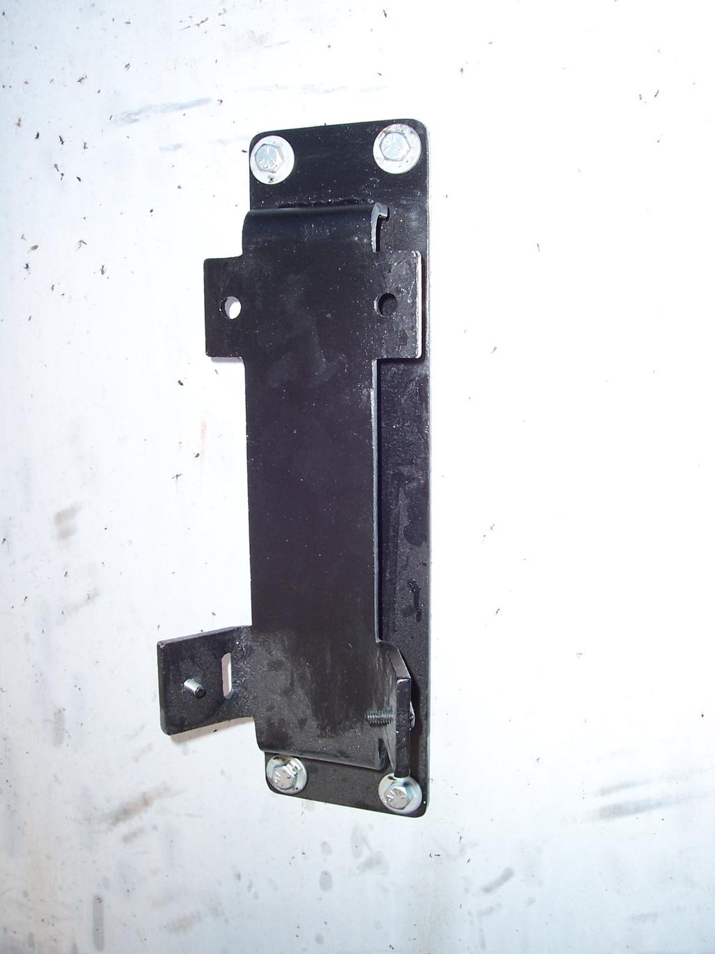
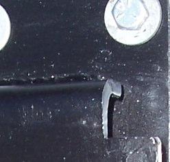
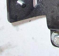
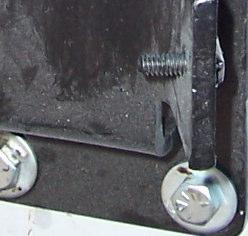
7 4. THE PLACEMENT OF THE HINGES IS SHOWN BELOW. IF THE TRAILER IS STEEL THE HINGES CAN BE WELDED INTO PLACE. ON AN ALUMINUM TRAILER USE THE HINGES AS A TEMPLATE, AND MARK THE HOLE LOCATIONS ON THE SIDE AND TOP OF TRAILER TOP RAIL. ON THE SIDE OF THE RAIL DRILL HOLES THROUGH TO THE IN SIDE OF TRAILER TO ACCEPT 1/2 (1.3cm) GRADE 5 (CLASS 8.8) OR BETTER BOLTS (NOT SUPPLIED). ON THE TOP RAIL DRILL + TAP 1/2-13 (M12) OR 1/2-20 (M12) TO ACCEPT 1/2 (1.3 cm) GRADE 5 (CLASS 8.8) OR BETTER BOLTS (NOT SUPPLIED). NOTE: TRAILERS WITH A CENTER SUPPORT ABOVE THE TOP RAIL MUST OFFSET THE CENTER HINGES TO EITHER SIDE OF THE SUPPORT. 6
8 5. BELOW ARE THE LIDS WITH THE CABLE EXTENSIONS SLID INTO PLACE. MEASURE THE TRAILER OUTSIDE WIDTH AT THE FRONT, CENTER AND REAR OF THE TRAILER. USE THESE DIMENSIONS FOR THE APPROPRIATE LID AS SHOWN BELOW, AND WELD EXTENSION TO LID AT THAT WIDTH. NOTE: BOTH FRONT AND REAR LID EX TENSIONS HAVE CABLES ATTACHED TO THEM. THE CENTER EXTENSION DOES NOT. 7


9 6. INSERT ROLLER AND SHAFT INTO ACTUATOR ARM AS SHOWN CAUTION!: AT THIS STAGE THE HYDRAULICS MUST BE INSTALLED, AND CYCLED TO ELIMINATE ANY AIR IN THE SYSTEM. FAILURE TO DO THIS COULD RESULT IN PERSONAL INJURY, AND/OR DAMAGE TO THE SYSTEM AT A LATER STAGE. 7. HOLD THE PUMP MOUNT BRACKET IN PLACE AS A TEMPLATE ON THE FRONT OF THE TRAILER JUST BELOW THE ACTUATOR UNIT (APPROX 12, (30.5cm)). MARK THE LOCATION OF THE (4) HOLES, AND DRILL THROUGH TO EXCEPT 3/8 x 1 1/2 (.88cm x 3.81cm) LONG BOLTS PROVIDED. USE WASHERS AND 3/8 (.88cm) LOCK NUTS PRO VIDED TO SECURE IN PLACE.. 8
")


")


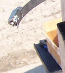


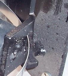
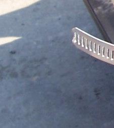
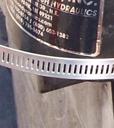


10 8. PLACE (4) RUBBER BUMPERS IN PLACE AS SHOWN AND SECURE PUMP BY USING 3/8-16 (.88cm) LOCK NUTS AND WASHERS. 3/8-16 (.88cm) LOCK NUT RUBBER BUMPERS 9. SECURE BOTTOM OF PUMP USING LARGE HOSE CLAMP AS SHOWN 10. CONNECT THE (2) HYDRAULIC HOSES (#3320) TO THE PUMP AND CYLINDERS AS SHOWN. USE THE HOSE CLIPS AND SELF DRILLING SCREWS PROVIDED TO ORGANIZE AND SECURE THE HOSES. HOSES (#3320) 9


 QUARTS (2.")

 TIMES TO REMOVE ANY")

 BOLTS, LOCK NUTS AND WASHERS PROVIDED.")
11 11. MOUNT CONTROL SWITCH AS SHOWN, WITH CABLE COMING FROM BOTTOM, USING (2) SELF DRILLING SCREWS PROVIDED. IMPORTANT: INSTALL THE CONTROL SWITCH IN AN AREA WHERE THE OPERATOR CAN SAFELY OBSERVE AND OPERATE THE SYSTEM. MOUNT THE QUICK DISCONNECT POWER CABLE NEAR THE CONTROL SWITCH SO THE OPERATOR HAS EASY ACCESS. USE THE HOSE CLIPS AND SELF DRILLING SCREWS PROVIDED TO ORGANIZE AND SECURE THE CABLES TO FRONT OF TRUCK. INSTALL ALL SAFETY STICKERS NEXT TO THE CONTROL SWITCH. SEE PAGE 17 FOR STICKER DESCRIPTION. REMOVE RED CAP FROM THE FILLER NECK ON PUMP, AND FILL PUMP WITH APPROXIMATELY (3) QUARTS (2.83 L) OF DEXTRON AUTOMATIC TRANSMISSION FLUID. REPLACE RED CAP WITH BLACK BREATHER CAP. NOTE: UNDER NORMAL OPERATING CONDITIONS THE FLUID IN THE HYDRAULIC PUMP WILL LAST THE LIFE OF THE PUMP. IN EXTREME DIRTY OR WET CONDITIONS, CHECK THE FLUID EVERY FOUR TO SIX MONTHS, AND CHANGE IF NECESSARY. 12. CONNECT A 12V POWER SUPPLY TO THE QUICK DISCONNECT POWER CABLE, AND CYCLE THE CYLINDER (10) TIMES TO REMOVE ANY AIR IN THE SYSTEM. FAILURE TO DO THIS COULD RESULT IN PERSONAL INJURY, AND/OR DAMAGE TO THE SYSTEM AT A LATER STAGE. 13. SLIDE FRONT LID ROLLER TRACK OVER THE ROLLER, AND ATTACH THE LID TO THE HINGES USING 1/2 x 3 (1.3cm x 7.6cm) BOLTS, LOCK NUTS AND WASHERS PROVIDED. THE FRONT LID AND HINGES (SHOWN) USE (4) BOLTS, THE REAR ALSO USE (4) BOLTS, AND THE CENTER LID USES (2) BOLTS. NOTE: THE FRONT LID WEIGHS 91 lb (41 Kg). USE A OVER HEAD LIFTING DEVICE, AND SLING TO LIFT INTO MOUNTING LOCATION. PLACE SLING AROUND TUBE AT LOCATION MARKED LIFTING POINT IN DRAWING BE- LOW. 10
12 14. MEASURE THE DISTANCE BETWEEN THE LIDS IN THE (2) PLACES SHOWN. 15. ADD 8 (20.3 cm) TO EACH OF THE (2) MEASUREMENTS TAKEN IN STEP #10. THIS WILL BE THE LENGTH OF THE LADDER SECTIONS BETWEEN THE LIDS. WELD THE H CONNECTORS AND LADDERS ON THE GROUND AS SHOW BELOW. THE LADDER SECTION MAY NEED TO BE CUT, AND/OR EXTRA H CONNECTORS AND LADDERS (SUPPLIED) MAY BE USED TO OBTAIN THE DESIRED LENGTH. NOTE: WHEN LADDER SECTIONS ARE WELDED TOGETHER THEY CAN WEIGH AS MUCH AS 70 lb (31.8 Kg). USE A OVER HEAD LIFTING DEVICE AND SLING TO LIFT INTO PLACE. LOCATE SLING AT THE CENTER OF THE WELDED LADDER SECTIONS TO EVENLY DISTRIBUTE THE WEIGHT. 11
13 16. RAISE THE APPROPRIATE LADDER SECTIONS INTO PLACE, AND SLIDE 4 (10.1cm) OF THE LADDER INTO EACH LID, AND WELD AROUND ALL FOUR SIDES OF EACH LADDER TO THE LID. 17. OPEN THE SYSTEM SO THE LID LAYS FLAT ON THE SIDE OF THE TRAILER TO INSTALL THE TARP CABLES AND TARP. THERE WILL BE TWO 30 LENGTH OF CABLE WITH TURNBUCKLES ATTACHED. EXTEND THE TURNBUCKLES SO THEY ARE FULLY EXTENDED. ATTACH EACH TURNBUCKLE TO THE CENTER LID AS SHOWN. 12
14 18. ATTACH ONE CABLE FROM THE CENTER LID TO THE FRONT LID EXTENSION. ATTACH THE OTHER CABLE FROM THE CENTER LID TO THE REAR LID EXTENSION. ATTACH THESE CABLES TO THE FRONT AND REAR EXTENSIONS USING ONE 3/16 THIMBLE AND TWO 3/16 CABLE NUTS PER END. PULL CABLES AS TIGHT AS POSSIBLE BY HAND AND SECURE THE CABLE NUTS (TIGHTEN TO APPROX. 30FT.-LB (40.6NM)) 19. TIGHTEN BOTH TURNBUCKLES UNTIL THE CABLES ARE TAUGHT. NOTE: DO NOT OVER TIGHTEN THE TURNBUCKLES, THIS COULD CAUSE EXCESS STRESS ON THE LIDS AND HINGES. TIGHTEN THE JAM NUTS ON EACH TURNBUCKLE TO PREVENT LOOSENING (USE OF A LIQUID THREAD LOCKER IS RECOMMENDED ON THE JAM NUTS). 20. ATTACH THE TARP STARTING AT THE FRONT LID WORKING YOUR WAY TO THE BACK ON THE CABLE ONLY USING A ZIP-TIE AT EVERY12 to 18 (30.5cm to 45.7cm) AS SHOWN. (TARP IS SHOWN INSTALLED) ATTACH TARP ALONG CABLE 21. TILT THE LID TO THE POSITION SHOWN AND ATTACH THE TARP, STARTING FROM THE FRONT, TO THE SYSTEMS LADDER SIDE USING ZIP TIES EVERY 12 to 18 (30.5cm to 45.7cm). ATTACH TARP ALONG LADDER 13
15 22. ATTACH THE TARP ALONG THE FRONT LID WITH ZIP TIES. USE THE HOLES AND CHAIN LINKS WHERE PROVIDED. HOLES CHAIN LINK 23. FOR TRAILERS THAT ARE SHORTER THAN THE TARP LENGTH, CUT THE TARP AT THE BACK OF THE TRAILER, BUT LEAVE APPROX. 6 to 8 (15.2cm to 20.3cm) EXTRA MATERIAL. FOLD OVER THE EXCESS MATERIAL, AND ZIP TIE ALONG REAR LID. TIP: IF THERE IS A GAP BETWEEN THE REAR LID, AND THE TRAILER REAR DOOR, DO NOT CUT THE EXCESS TARP MATERIAL. ROLL THE EXCESS TARP MATERIAL UP AND ZIP-TIE IT TO THE REAR LID TO HELP COVER THE GAP. NOTE: 2 (5cm) WIDE SPLICING TAPE IS SUPPLIED, AND CAN BE USED TO PROTECT THE TARP BY WRAPPING A SMALL LENGTH AROUND ANY SHARP POINTS ON THE SYSTEM. 14
16 25. INSTALL THE WIND DEFLECTOR OVER THE HYDRAULIC UNIT USING (6) STAINLESS STEEL BUTTON HEAD BOLTS, (3) AT 3 (7.6cm) AND (3) AT 2 (5cm). USE THE LARGE WIND DEFLECTOR BRACKET ON THE LEFT, AND THE SMALL WIND DEFLECTOR BRACKET ON THE RIGHT AS SHOWN BELOW (OPPOSITE IF THE INSTALL IS ON THE PASSENGER SIDE. USE THE LOC-TITE PROVIDED ON THE (1) MIDDLE BOLT SHOWN, AND LOCK NUTS ON THE (5) REMAINING BOLTS. PERIODIC MAINTENANCE and INSPECTION: -Daily: 1. Check mechanism for any damage or cracks. 2. Check tarpaulin for excessive wear and tear. 3. If equipped, check electrical cables for insulation damage. 4. Check hoses and fittings for cracks and leaks. 5. Check tarpaulin cable and adjust if loose. - Weekly: 1. Check cylinders for leaks or excessive wear. 2. Check tightness of the fasteners. 3. Check hinges for excessive wear. 4. Check hydraulic actuator for any cracks, damage or excessive wear. 5. If equipped, check the hydraulic fluid level in hydraulic pump. - Monthly: 1. Operate system to verify proper safe operation. 2. Check roller trolley and bearing for damage in front lid. 15
17 OPERATING INSTRUCTIONS CAUTION: BEFORE OPERATING THIS OR ANY TARPER, CHECK YOUR SURROUNDINGS. LOOK FOR OVERHEAD POWER LINES, TREE LIMBS, ETC.. DO NOT OPERATE SYSTEM WHEN DANGER OF LIGHTNING STRIKE IS PRESENT. CAUTION: When servicing or repairing the Sidewinder II system, disconnect power to the components from the vehicles battery. NOTE: The noise level is less than 72dB(A) TO OPEN TARP PRESS UP ON SWITCH LEVER TO OPEN LID. TO CLOSE TARP PRESS DOWN ON SWITCH LEVER TO CLOSE LID. 16


18 SAFETY STICKERS 17
19 LIFT-N-LOAD WET KIT 1. CONNECT T FITTING TO HYDRAULIC RETURN LINE. 2. CONNECT PRIORITY FLOW CONTROL VALVE TO HYDRAULIC SUPPLY LINE. 3. ATTACH HANDLE TO FRONT OF TRAILER IN A SUITABLE LOCATION FOR OPERATION. 4. HOOK UP 9 HYDRAULIC HOSE TO THE TRAILER S CENTER-MOST HYDRAULIC CYLINDER FITTING. 5. HOOK UP 8 HYDRAULIC HOSE TO THE TRAILER S OUTER-MOST HYDRAULIC CYLINDER FITTING. 6. WITH HYDRAULICS BEING SUPPLIED TO PRIORITY FLOW CONTROL VALVE, CYCLE HAND VALVE BACK AND FORTH 3 TO 4 TIMES TO PURGE ANY AIR FROM HYDRAULIC LINES. T FITTING HYDRAULIC RETURN LINE FROM TRAILER PRIORITY FLOW CONTROL VALVE HYDRAULIC PRESSURE LINE FROM TRAILER HYDRAULIC RETURN LINE FROM TRUCK S TANK HYDRAULIC PRESSURE LINE TO TRAILER 9 HYDRAULIC HOSE TO CENTER-MOST HYDRAULIC FITTING 8 HYDRAULIC HOSE TO OUTTER-MOST HYDRAULIC FITTING 18
20 LIFT-N-LOAD WET KIT PARTS BREAKDOWN CONTROL VALVE P/N:1614 PRESSURE CONTROL VALVE REDUCER 1 NPTM to 1/4 NPTF P/N: MALE BRANCH TEE FLOW DIVIDER (PRI FLOW CONTROL) 1 GPM P/N:2641 1/4 NPTM to #4JICM 90deg P/N:572 #4 JICM to #8 ORBM 90deg P/N:1061 #4 JICM to #8 ORBM 90deg P/N:1061 1/4 NPTM to 1/4 NPTF 90deg P/N:1610 1/4 NPTM to 1/4 JICM P/N:2960 CONTROL VALVE P/N:1614 FLOW CONTROL P/N:2533 1/4 NPT to 1/4 NPT HEX NIPPLE P/N:1622 REDUCER #8 SAE ORBM to 1/4 NPTF P/N:1613 1/4 NPTM to 1/4 NPTM 90deg P/N:
21 9 HOSE w/ both ends #4 JICF P/N: HOSE w/ both ends #4 JICF P/N: HOSE w/ both ends #4 JICF P/N: HOSE w/ both ends #4 JICF P/N:
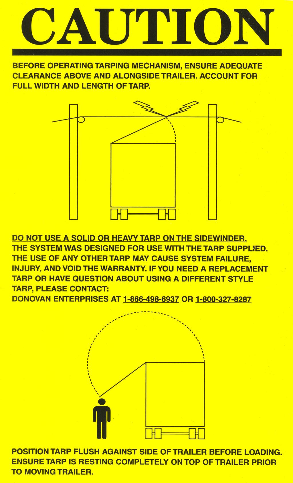
SIDEWINDER 350 INSTALLATION INSTRUCTIONS & OPERATION MANUAL NOVEMBER 2011
 SIDEWINDER 350 INSTALLATION INSTRUCTIONS & OPERATION MANUAL NOVEMBER 2011 PATENT PENDING Donovan Enterprises 3353 SE Gran Park Way, Stuart FL 34997 800-327-8287 www.donovan-ent.com PACKING LIST FOR SIDEWINDER
Easy Cover. Installation Instructions. Attention Dealers: Please give this owners manual to the customer when the product is delivered.
 Serving the Truck & Trailer Industry Since 944 Easy Cover Attention Dealers: Please give this owners manual to the customer when the product is delivered. Call 00-3-94 www.aeroindustries.com Indianapolis,
INSTALLATION, MAINTENANCE, & SAFETY INSTRUCTIONS
 Tarpaulin Systems Flip -N- Go / Quick Mount Flip -N- Go System INSTALLATION, MAINTENANCE, & SAFETY INSTRUCTIONS (800) CRAMARO (800) 272-6276 Plants In: Delaware, Florida, Massachusetts, Nevada, Ohio Install
Installation Instructions. Attention Dealers: Please give this owners manual to the customer when the product is delivered.
 Serving the Truck & Trailer Industry Since 1944 Attention Dealers: Please give this owners manual to the customer when the product is delivered. Call 800-535-9545 www.aeroindustries.com Indianapolis, IN
MENTOR INSTALLATION, MAINTENANCE, & SAFETY INSTRUCTIONS (800)
") MENTOR INSTALLATION, MAINTENANCE, & SAFETY INSTRUCTIONS (800) 272-6276 001-321-757-7611 www.cramarotarps.com Plants In: Delaware, Florida, Massachusetts, Nevada, Ohio, and Canada Important: Read before
MENTOR INSTALLATION, MAINTENANCE, & SAFETY INSTRUCTIONS (800) 272-6276 001-321-757-7611 www.cramarotarps.com Plants In: Delaware, Florida, Massachusetts, Nevada, Ohio, and Canada Important: Read before
table of Contents Warranty:
 table of Contents placement of the Mounting Bolts spudnik swingout... 2 spudnik solid... 2 logan swingout... 3 logan solid... 3 double l swingout... 4 double l solid... 4 Mounting Framework... 5-6 Mounting
Website: ELIMINATOR MD. (701) (800)
 (800)") Website: www.tbei.com E-mail: sales@tbei.com ELIMINATOR MD www.rugbymfg.com sales@rugbymfg.com (701) 776-5722 (800) 533-0494 1228633 1 DATE PURCHASED BODY SERIAL NUMBER HOIST SERIAL NUMBER CYLINDER SERIAL
Website: www.tbei.com E-mail: sales@tbei.com ELIMINATOR MD www.rugbymfg.com sales@rugbymfg.com (701) 776-5722 (800) 533-0494 1228633 1 DATE PURCHASED BODY SERIAL NUMBER HOIST SERIAL NUMBER CYLINDER SERIAL
Patriot. Aluminum and Steel 5spring. Step #1 Tarp Spool with Gear Motor (Includes Instructions for Optional Wind Deflector)
") Aluminum and Steel 5spring Qty. Component Parts Description: LONG BOX: (1) 103 Aluminum Tarp Axle (2) 98 Upper Arms with 90 Degree Elbow (2) Lower Aluminum ( 84 ) (1) Aluminum Cross Tube SMALL HARDWARE
Aluminum and Steel 5spring Qty. Component Parts Description: LONG BOX: (1) 103 Aluminum Tarp Axle (2) 98 Upper Arms with 90 Degree Elbow (2) Lower Aluminum ( 84 ) (1) Aluminum Cross Tube SMALL HARDWARE
Installation Instructions Models 2858, 2858A-1, 2858GL February 2009
 Installation Instructions Models 2858, 2858A-1, 2858GL February 2009 www.donovan-ent.com Donovan Enterprises 3353 SE Gran Park Way Stuart, FL 34997 800-327-8287 Step 1 Head Assembly Installation Instructions
Part Name/Description Part Number Quantity Instruction Kit Metalfor Flow Sensor
 NOTE: Indented items indicate parts included in an assembly listed above Part Name/Description Part Number Quantity Instruction Kit Metalfor 4101091 1 Flow Sensor 4001356 1 Deflector plate 2000612-1 1
CRYSTEEL S HOIST. this manual must be included with the vehicle after completing the installation.
 Website: www.tbei.com E-mail: sales@tbei.com CRYSTEEL S STINGRAY HOIST this manual must be included with the vehicle after completing the installation. Web Site E-Mail Phone (507) 726-2728 www.crysteel.com
DODGE CUMMINS 24V ISB
 2/9/2012 1998-2002 Dodge Cummins OEM Bypass Lift Pump Kit # 1050229-1 - 1998-2002 DODGE CUMMINS 24V ISB OEM BYPASS LIFT PUMP KIT Installation Instructions P/N# 1050229 PLEASE READ ALL INSTRUCTIONS CAREFULLY
N. 15th Street, Middlesboro, KY CRUSHED CAR HAULER INSTALLATION INSTRUCTIONS
 1-800-248-7717 1002 N. 15th Street, Middlesboro, KY 40965 CRUSHED CAR HAULER INSTALLATION INSTRUCTIONS Congratulations on your purchase of a Mountain Tarp Crushed Car Hauler tarping system. With tarping
Combine Cover Manual
 Combine Cover Manual Installation Instructions Page 26 Operating Instructions Page 7 Warranty Page 7 Trouble Shooting Page 8 10 For Big Top Extension Model s: Case I.H. 8010, 8120 Please forward onto Customer
A B C D E F. Tools Required (supplied by others)
") Page 1 of 17 Parts List Below Deck Automatic Retractable Security Cover Kit (1) Tube End Bearing Plate (A) (1) Rope Reel and Cover Drum Motor Assembly (B) (1) Cover Drum (1) Pulley Support Channel (2)
Page 1 of 17 Parts List Below Deck Automatic Retractable Security Cover Kit (1) Tube End Bearing Plate (A) (1) Rope Reel and Cover Drum Motor Assembly (B) (1) Cover Drum (1) Pulley Support Channel (2)
Installation Instructions February 2009
 Installation Instructions February 2009 www.donovan-ent.com Donovan Enterprises 3353 SE Gran Park Way Stuart, FL 34997 800-327-8287 The Hammer Head Assembly Installation Instructions (Rollerbar & Direct
Siderolling Tarp Systems Under 9 6 Wide
 Load Loc Select Maximizer Grain Carts Grain Bagger Siderolling Tarp Systems Under 9 6 Wide CRANK STYLE INSTALLATION INSTRUCTIONS MICHEL S INDUSTRIES, LTD. P.O. BOX 119 ST. GREGOR, SK. S0K 3X0 PH:306.366.2184
Fold Hydraulics Item Qty Part No. Description
 Fold Hydraulics 1 2 465385 Quick Coupler 3/4"-16 FOR 2 2 469882 Hose ½" x 468" (3/4 FJSw x 3/4 MOR) 3 2 469833 Hose ½" x 87" (3/4 FJSw) 4 4 465310 Adapter 90 (3/4 MOR x 3/4 JICM) 5 2 469866 Hose ½" x 230"
CRYSTEEL S. this manual must be included with the vehicle after completing the installation.
 Website: www.tbei.com E-mail: sales@tbei.com CRYSTEEL S POWER TAILGATE this manual must be included with the vehicle after completing the installation. Web Site E-Mail Phone (507) 726-2728 www.crysteel.com
PFadvantage MF 6850/6855; Ideal 9080/9090
 MF 6850/6855; Ideal 9080/9090 Note: Indented items indicate parts included in an Quantity by Model assembly listed above MF Ideal Part Name/Description Part Number 6850 6855 9080 9090 Instruction Kit MF
WARNING: the engine does not come with oil in it. Please fill the oil before starting. The 200cc hardknock requires 9/10 of a quart of oil.
 WARNING: the engine does not come with oil in it. Please fill the oil before starting. The 200cc hardknock requires 9/10 of a quart of oil. Things needed for assembly. -2 tubes of blue loc-tite. I don
2-row and All-row systems included.
 Ag Leader Technology Cotton Picker Installation Installation Instructions for John Deere cotton picker models: 2-row and All-row systems included. IMPORTANT: Ensure the model numbers shown above correspond
Universal Super Shield & Ultimate Aluminum w/electric Drive Conversion Kits , , Installation Instructions
 WLH 09/19/16 111-0215 & 112-0215 607-0026 For technical support call us at (800) 368-3075 or visit our website at PullTarps.com. TABLE OF CONTENTS ***Assembly*** Conversion Kit-Universal Super Shield ***Wiring,
Installation Instructions
 Installation Instructions ELECTRIC CONVERSION KIT 3 ALUMINUM ROLL TUBE IMPORTANT: This Electric Conversion Kit has been designed for systems with a 3 aluminum roll tube. It is assumed that the tarping
Start-up and Operation
 Start-up and Operation NEVER FORGET THAT ANY MACHINE CAN BE VERY DANGEROUS WHEN NOT OPERATED CORRECTLY AND SAFELY. ALWAYS VISUALLY CHECK TO MAKE SURE THAT ALL PERSONS ARE CLEAR BEFORE TURNING ON ANY CONTROLS.
Combine Cover Manual
 Combine Cover Manual Installation Instructions Page 27 Operating Instructions Page 8 Warranty Page 8 Trouble Shooting Page 9 11 For Model s: Case I.H. 2388, 2188, 1688 and 1680 With a MAURER Hopper Extension
Suspension System RS6582B
 Suspension System RS6582B Tahoe/Yukon READ ALL INSTRUCTIONS THOROUGHLY FROM START TO FINISH BEFORE BEGINNING INSTALLATION IMPORTANT NOTES! WARNING: This suspension system will enhance the off-road performance
A B C D E F. b.tools Required (supplied by others) 3/16" Drill Bit 3/8" Wrench Phillips Head Screwdriver
 3/16 Drill Bit 3/8 Wrench Phillips Head Screwdriver") Page 1 of 13 5E.1 Parts List a. Below Deck Automatic Retractable Security Cover Kit (1) Tube End Bearing Plate (A) (1) Rope Reel with Motor Attached (B) (1) Rope Reel Cover (C) (1) Cover Drum (1) Cover
Page 1 of 13 5E.1 Parts List a. Below Deck Automatic Retractable Security Cover Kit (1) Tube End Bearing Plate (A) (1) Rope Reel with Motor Attached (B) (1) Rope Reel Cover (C) (1) Cover Drum (1) Cover
2000SR. Installation Instructions May Donovan Enterprises 3353 S.E. Gran Park Way Stuart, Florida
 311499-Donovan 4/28/04 11:22 PM Page 1 Installation Instructions May 2003 Donovan Enterprises 3353 S.E. Gran Park Way Stuart, Florida 34997 1-800-327-8287 Visit our web site at: www.donovan-ent.com 311499-Donovan
GRAIN CART TARP SYSTEM INSTALLATION AND OPERATION MANUAL
 GRAIN CART TARP SYSTEM INSTALLATION AND OPERATION MANUAL Grain Carts KITS Thunderstone Manufacturing, LLC. 3400 West O Street Lincoln, NE 68528 402-435-4249 (Fax) 402-438-3918 www.thunderstonemfg.com Aluminum
PFadvantage Metalfor Araus 1360
 Metalfor Araus 1360 Note: Indented items indicate parts included in an assembly listed above Part Name/Description Part Number Quantity Instruction Kit Metalfor Araus 2005300-14 1 Display Bracket 4000134
L/6.7L DODGE CUMMINS
 6/15/2016 #1050310D 2005-09 5.9/6.7 Dodge Cummins FlowMAX Lift Pump Kit (I-00170) - 1-2005-09 5.9L/6.7L DODGE CUMMINS BD FLOWMAX LIFT PUMP KIT Installation Instructions P/N # 1050310D PLEASE READ ALL INSTRUCTIONS
MARATHON TELESCOPIC HOIST
 Website: www.tbei.com E-mail: sales@tbei.com CRYSTEEL S MARATHON TELESCOPIC HOIST this manual must be included with the vehicle after completing the installation. Web Site E-Mail Phone (507) 726-2728 www.crysteel.com
JEEVES. JEEVES Installation Manual. Installation Manual The Easiest Do-It-Yourself Dumbwaiter on the Market
 1 888-323-8755 www.nwlifts.com JEEVES Installation Manual The Easiest Do-It-Yourself Dumbwaiter on the Market This manual will cover the installation procedure step-by-step. The installation of this dumbwaiter
Easy Cover. Installation Instructions. Attention Dealers: Please give this owners manual to the customer when the product is delivered.
 Serving the Truck & Trailer Industry Since 1944 Model 9 10 Spring Flange Mount Easy Cover Attention Dealers: Please give this owners manual to the customer when the product is delivered. Call 800-3-94
In area - A -, a proper seal must be made against the top of the window glass.
 Door window, adjusting Page 1 of 3 Audi > B3 > 1994-1998 Body Exterior, Interior 61 - Convertible top, checking and adjusting Door window, adjusting Sections C-C and D-D. Adjust door window so that window
Parts Manual FRONT-FOLD BOOMS MODELS 80, 90 & 100 HYDRAULIC FOR TA1200 & TA1600 SPRAYERS. Serial Number B & Higher. Part No.
 Parts Manual FRONT-FOLD BOOMS MODELS 80, 90 & 100 HYDRAULIC FOR TA1200 & TA1600 SPRAYERS Serial Number B30970200 & Higher Part No. 408920 Front-Fold Booms 80 / 90 / 100 Introduction Foreward This symbol
CHEVY/GMC /2-TON PICKUP 3 BODY LIFT INSTALLATION INSTRUCTIONS 2006 KIT# PA10163 MANUAL TRANSMISSION VEHICLES REQUIRE KIT# PA4701
 3651 N Highway 89 Chino Valley, AZ 86323 (928) 636-7080 www.p-a-g.net CHEVY/GMC 1500 1/2-TON PICKUP 3 BODY LIFT INSTALLATION INSTRUCTIONS 2006 KIT# PA10163 MANUAL TRANSMISSION VEHICLES REQUIRE KIT# PA4701
PFadvantage JD 3300/4400/6600/7700; 4420
 Ag Leader Technology Combine Installation JD 33//66/77; 2 Note: Indented items indicate parts included Quantity by Model in an assembly listed above Early Late Part Name/Description Part Number 3 3 6 6
Assembly Instructions
 Assembly Instructions Part Number Description Model Approx. Assembly Time 99994-049 Cab Enclosure MULE SX 3-4 Hours WARNING Improper installation of this accessory could result in an accident causing serious
WARNING TAKE NOTE OF THE FOLLOWING: THIS PRODUCT MUST BE INSTALLED EXACTLY AS PER THESE INSTRUCTIONS USING ONLY THE HARDWARE SUPPLIED.
 ARB WINCH/NONWINCH BUMPER TO SUIT TOYOTA HJ100 IFS PRODUCT No. 3913140 5100050 Top Tube Kit 5100160 Buffer Kit With hole (required when fitting Top Tube) 5100170 Buffer Kit With no hole Fitting Kit No.
Side Dump Tarp System Driver or Passenger Stowing Non-Sealed applications
 Roll Rite, LLC and its entire staff would like to not only Thank You but congratulate you on your purchase of one of what we feel to be the finest line of tarping systems in the industry. Side Dump Tarp
Lexion 570R/575R, 580R/585R, 590R/595R
 Note: Indented items indicate parts included in an assembly listed above Quantity by Model 2006+ All Years Part Name/Description Part Number 570R 575R 580R 585R Instruction Kit Lexion 570/580/590 2005500-5
MODEL NO & UP MODEL NO & UP MODEL NO & UP MODEL NO & UP
 MODEL NO. -900 & UP MODEL NO. 00-900 & UP MODEL NO. 0-900 & UP MODEL NO. 0-900 & UP SKID SPRAYER FORM NO. 99-055 REV. B SET-UP AND PARTS LIST Refer to the illustrated Parts List for the details of parts
OEM BYPASS LIFT PUMP KIT
 6 March 2014 # 1050227 2003-04.5 Dodge Cummins OEM Bypass Lift Pump Kit (I-00164) - 1-2003-04½ DODGE CUMMINS OEM BYPASS LIFT PUMP KIT Installation Instructions Part # 1050227 PLEASE READ ALL INSTRUCTIONS
5000 Series Covering Systems Installation Instructions
 ENTERPRISES Donovan R a I s e T h e S t a n d a r d 5000 Series Covering Systems Installation Instructions The following hardware is universal to all kits: Bent arm extension (L) 1 905 Hose clamp 1 ½ 4
'99-03 CHEVROLET/GMC IFS 4WD 6" SUSPENSION SYSTEM P/N INSTALLATION INSTRUCTIONS
 1/16/04 '99-03 CHEVROLET/GMC IFS 4WD 6" SUSPENSION SYSTEM P/N. 10-41099 INSTALLATION INSTRUCTIONS NOTE: Each Lift Kit and options to Lift Kits are packaged separately. Therefore, installation procedures
Liftgate Terminology
 SL-20 Series SL-20 Series Click the appropriate link below for the major component of the liftgate for which you are trying to find the correct part. If you are unsure of the name of the part in Waltco
CONTAINER GUIDE WELDMENTS
 CONTAINER GUIDE WELDMENTS FOR MODELS - ALL FRONT LOAD CONTAINERS 4/98 1 9110--39--0 L.H. Container Guide Weldment 1 2 9110--38--0 R.H. Container Guide Weldment 1 3 9110--56--1 Instruction Sheet (Not Shown)
Illustrated Parts & Packing List & Instructions 815 Rice Lake Street, Owatonna, MN 55060
 Illustrated Parts & Packing List & Instructions 815 Rice Lake Street, Owatonna, MN 55060 Great Plains Part #891-561C (Gandy Part #6245DS-GP) For Great Plains Turbo-Max 2400, 3000, 3500 & 4000 Models 45
FaceClipper Model # Serial #
 FaceClipper 000 Model # Serial # Vertex Fasteners A Subsidiary of Leggett & Platt, Inc. 798 Sherwin Avenue Des Plaines, Illinois 6008 U.S.A. (87) 768-69 REV. O Table of Contents OF EQUIPMENT... OPERATION
Illustrated Parts & Packing List & Instructions 815 Rice Lake Street, Owatonna, MN 55060
 Illustrated Parts & Packing List & Instructions 815 Rice Lake Street, Owatonna, MN 55060 Great Plains Part #891-622C (Gandy Part #6245DS-TT) Great Plains Turbo-Till & Turbo-Chopper 2400/3000 Models 45
PARTS LIST WRANGLER 1710AB, 2010AB 120V AND 240V, TYPE F PLUG
 PARTS LIST WRANGLER 1710AB, 2010AB 120V AND 240V, TYPE F PLUG CONTROL PANEL ASSEMBLY 101 1394151 ROUND POWER SWITCH 1 102 0693141 RUBBER SWITCH BOOT 2 103 9122465.516 I.D. X.813 O.D. X.027/.030 THICK FLAT
Tusk Pannier Racks. Instructions and information KLR
 1 Tusk Pannier Racks Instructions and information KLR650 2008 + Congratulations on your purchase of the Tusk Pannier Racks. These racks are made to handle extreme adventure riding, but work great for the
MODEL NO & UP MODEL NO & UP MODEL NO & UP MODEL NO & UP MODEL NO.
 9-0688 MODEL NO. 00-800 & UP MODEL NO. 0-800 & UP MODEL NO. 5-800 & UP MODEL NO. -800 & UP MODEL NO. 0-800 & UP SKID SPRAYER with the Diaphragm Pump FORM NO. 95-90 SET-UP AND PARTS CATALOG SAFETY AND INSTRUCTION
Side Kick 2. Installation Instructions & Parts Lists. Attention Dealers: Please give this owners manual to the customer when the product is delivered.
 Serving the Truck & Trailer Industry Since 1944 Side Kick 2 Installation Instructions & Parts Lists Attention Dealers: Please give this owners manual to the customer when the product is delivered. Call
Instructions for 2-row monitoring only
 Installation Instructions for CaseIH cotton picker models: Instructions for 2-row monitoring only CAUTION: Ensure the model numbers shown above correspond to the machine model. If you receive the incorrect
ASSEMBLY MANUAL. 45-Foot Air Double Disc Drill. Amity Technology, LLC th Avenue North Fargo, ND (701)
") ASSEMBLY MANUAL 45-Foot Air Double Disc Drill Amity Technology, LLC 2800 7th Avenue North Fargo, ND 58102 (701) 232-4199 www.amitytech.com TABLE OF CONTENTS Main Frame 1 Wing Lock Towers 3 Wing Frames
ASSEMBLY MANUAL 45-Foot Air Double Disc Drill Amity Technology, LLC 2800 7th Avenue North Fargo, ND 58102 (701) 232-4199 www.amitytech.com TABLE OF CONTENTS Main Frame 1 Wing Lock Towers 3 Wing Frames
WARNING. When installed in accordance with these instructions, the front protection bar does not affect operation of the SRS airbag.
 Part Number: 36030 Product Description: BULL BAR WINCH TYPE Suited to vehicle/s: CHEVROLET C/K 500-3500 988-998 YEAR MODEL RANGE AND Warn 9,500-5,000lb WINCHES WARNING REGARDING VEHICLES EQUIPPED WITH
Instructions for 2-row monitoring only
 Installation Instructions for CaseIH cotton picker models: Instructions for 2-row monitoring only Ensure the model numbers shown above correspond to the machine model. If you receive the incorrect installation
INSTALLATION & OWNER S MANUAL
 Rev. C p. 1 of 21 INSTALLATION & OWNER S MANUAL F5205 HARD SIDED CAB KIT INSTALLATION & OWNER S MANUAL The contents of this envelope are the property of the owner. Be sure to leave with the owner when
INSTALLATION INSTRUCTIONS SEMI-HIDDEN WINCH MOUNT Part Number:70005 Application: Ford Super Duty
 INSTALLATION INSTRUCTIONS SEMI-HIDDEN WINCH MOUNT Part Number:70005 Application: Ford Super Duty Your safety, and the safety of others, is very important. To help you make informed decisions about safety,
WARNING WARNING CAUTION. Warnings and Cautions MOVING PARTS ENTANGLEMENT HAZARD MOVING PARTS ENTANGLEMENT HAZARD CHEMICAL AND FIRE HAZARD
 Warnings and Cautions As you read these instructions, you will see S, S, NOTICES and NOTES. Each message has a specific purpose. S are safety messages that indicate a potentially hazardous situation, which,
NOTE: Skids, springs, center section, and hardware are located in the push tube box.
 72 HYDRAULIC V-PLOW MOUNTING INSTRUCTIONS BLADE P/N: 4501-0190 PUSH TUBE ASSM P/N: 4501-0191 CUSTOMER MUST RECEIVE A COPY OF THIS INSTRUCTION SHEET AT THE TIME OF SALE NOTE: Skids, springs, center section,
WARNING!! C-659 SUBKIT FIGURE 4
 '0-'0 DODGE / TON TRUCKS '03-' DODGE 3/ & TON TRUCKS (WILL FIT /, 3/ & TON MEGA CAB SHORT BED) WARNING!! BRAKE, FUEL, AND ELECTRICAL LINES MAY NEED TO BE LOOSENED OR REPOSITIONED TO PROVIDE CLEARANCE FOR
baseplate Chevrolet Equinox
 , Rev 3 06/16 baseplate 9518316 Chevrolet Equinox Pin height - 14-3/4 Centers - 24-1/4 25. ITEM PART # QTY DESCRIPTION 1 00057 2.25 LOCKWASHER 2 00059 8.375 FLATWASHER 3 00060 24.375 LOCKWASHER 4 00061
CATALOG OF REPLACEMENT PARTS
 CATALOG OF REPLACEMENT PARTS HBA ELECTRIC RACK OVENS ML-132361 ML-132355 HBA1E HBA2E A product of HOBART 701 S. RIDGE AVENUE TROY, OHIO 45374-0001 FORM 43097 Rev. B (September 2014) F-43097 Rev. B (September
Illustrated Parts & Packing List 528 Gandrud Road, Owatonna, MN For a complete distributor & dealer list go to
 Illustrated Parts & Packing List 528 Gandrud Road, Owatonna, MN 55060 For a complete distributor & dealer list go to www.gandy.net 66GW27F Orbit-Air Applicator 120 Cu. Ft. Hopper w/ 27 (2 ) Openings, Fertilizer
INSTALLATION INSTRUCTIONS
 INSTALLATION INSTRUCTIONS Thank you for purchasing an AUTOLOCK Electric Tarp. ACI proudly manufactured this product using superior quality materials and workmanship. With proper care, your tarp will provide
Parts Manual HLF 2500, 3000, 4000 & 5000 lb. Capacity Flipaway Liftgates
 www.waltco.com Phone: 800.4.5685 parts@waltco.com Fax: 800.4.5684 Parts Manual HLF 500, 3000, 4000 & 5000 lb. Capacity Flipaway Liftgates EO:7 Rev 7 This manual identifies parts for Liftgates manufactured:
JK RockBrawler II Rear Bumper with Tire Carrier
 INSTALLATION INSTRUCTIONS INST-17-62-020_A JK RockBrawler II Rear Bumper with Tire Carrier IMPORTANT: Thank you for purchasing this Poison Spyder product. Please read through this entire document before
INSTALLATION INSTRUCTIONS
 INSTALLATION INSTRUCTIONS INSTALLATION INSTRUCTIONS THESE INSTRUCTIONS COVER THE INSTALLATION OF THE FOLLOWING REAR DOORS WITH OUTSIDE CABLES AND MAXIMUM SECURITY LOCK: 3/4" and 1" DryFreight TODCOLD Insulated
N. 15th Street, Middlesboro, KY TARP-N-GO SYSTEMS INSTALLATION INSTRUCTIONS
 1-800-248-7717 1002 N. 15th Street, Middlesboro, KY 40965 TARP-N-GO SYSTEMS INSTALLATION INSTRUCTIONS Congratulations on your purchase of a Mountain Tarp Tarp-N-Go tarping system. With tarping systems
R O A D M A S T E R, I N C.
 R O A D M A S T E R, I N C. 6 13 11 MOUNTING BRACKET KIT Cable Tab 14 12 7 15 9 Cable Tab 2 8 10 ITEM QTY NAME MATERIAL 1... 4...1/2 x 1 3/4 BOLT... 350096-00 2... 2...1/2 x 5 1/2 BOLT... 350108-00 3...
EASY DUMP RD3100 / RD3106 (Standard)-(60/40 Split)-(60/40 Divider)- (70/30 Split with Bayne) USER S MANUAL
-(60/40 Split)-(60/40 Divider)- (70/30 Split with Bayne) USER S MANUAL") EASY DUMP RD3100 / RD3106 (Standard)-(60/40 Split)-(60/40 Divider)- (70/30 Split with Bayne) USER S MANUAL *** Important *** Read User s Manual Completely Prior to Operating Par-Kan Company Phone: 1-800-291-5487
EASY DUMP RD3100 / RD3106 (Standard)-(60/40 Split)-(60/40 Divider)- (70/30 Split with Bayne) USER S MANUAL *** Important *** Read User s Manual Completely Prior to Operating Par-Kan Company Phone: 1-800-291-5487
C-10 INSTALLATION INSTRUCTIONS
 GROSS LOAD CAPACITY WHEN USED AS A WEIGHT CARRYING HITCH: 30,000 LBS. TRAILER WEIGHT & 6,000 LBS. TONGUE WEIGHT. ***DO NOT EXCEED VEHICLE MANUFACTURER'S RECOMMENDED TOWING CAPACITY.*** Parts List ITEM
Smooth Roll Advantage Side Dump
 Smooth Roll Advantage Side Dump Installation, Maintenance and Safety Instructions Sioux City Tarp 5201 Harbor Drive Sioux City, IA 51111 Ph: 712-258-6939 Getting Started Important: Please read manual thoroughly
INSTALLATION INSTRUCTIONS 97 FORD EXPEDITION
 INSTALLATION INSTRUCTIONS 97 FORD EXPEDITION 1. Read the instructions completely and carefully before you begin. Check the kit for proper contents (refer to the part s list and the picture diagrams). Before
OPERATOR S MANUAL MAINTENANCE MANUAL PARTS LIST TURFCO CR-7. Broadcast Top Dresser. Product Number Starting Serial Number P00851
 OPERATOR S MANUAL MAINTENANCE MANUAL PARTS LIST TURFCO CR- Broadcast Top Dresser Product Number 0 Starting Serial Number P00 US Patent,,0,,0, and,, Manual Number DANGER - IF INCORRECTLY USED THIS MACHINE
INSTALLATION INSTRUCTIONS
 INSTALLATION INSTRUCTIONS HD BUMPER Kit 66240 (BLACK), 74760 (BLACK) & 74690 TUBELESS (TEXTURED BLK) For 03-Newer Chevy 3/4 Ton Trucks As you read these instructions, you will see NOTES, CAUTIONS and WARNINGS.
Model ET 5000W Operation and Service Manual
 Model ET 5000W Operation and Service Manual Patented 5/16 BALL Load Capacity: 5000 lbs The ET 5000W ESCALATE TRAILER offers ground level roll-on loading and roll-off unloading of equipment with non-tilting
TT8101 Rotary Tedder
 TT0 Rotary Tedder Illustrated Parts Breakdown Page Front End Page Page Transport Axle Assembly Cylinder Linkage Page Guards Page Page Page Page Transport Lock Assembly Lift Frame Assembly Center Tunnel
Flow Sensor
 NOTE: Indented items indicate parts included in an assembly listed above Part Name/Description Part Number Quantity Instruction Kit Metalfor 4101091 1 Quick reference sheet 2002831-36 1 Installation instructions
Parts Manual MZ52 /
 Gasoline containing up to 10% ethanol (E10) is acceptable for use in this machine. The use of any gasoline exceeding 10% ethanol (E10) will void the product warranty. Parts Manual MZ52 / 962401 Please
M-ZT 61. Parts Manual. Zero Turn Mower /
 Parts Manual M-ZT 61 Zero Turn Mower / 967177008-01 Please read the operator manual carefully and make sure you understand the instructions before using the machine. When you need spare parts or support
(31 ) ZEON CONTROL PACK RELOCATION KIT
 ZEON CONTROL PACK RELOCATION KIT") ORIGINAL INSTRUCTIONS SYMBOL INDEX (31 ) ZEON CONTROL PACK RELOCATION KIT SYMBOL EXPLANATION Read All Product Literature SYMBOL EXPLANATION Always Wear Leather Gloves INSTALLATION GUIDE Always Wear Hearing
ORIGINAL INSTRUCTIONS SYMBOL INDEX (31 ) ZEON CONTROL PACK RELOCATION KIT SYMBOL EXPLANATION Read All Product Literature SYMBOL EXPLANATION Always Wear Leather Gloves INSTALLATION GUIDE Always Wear Hearing
It don t mean a thing If it ain t got the swing
 SWING CHUTE SAND/SALT SPREADER INSTALLATION AND OPERATING INSTRUCTIONS SWING CHUTE SPREADER MODELS: 7, 8, 9, 9.5 & 10 MANUAL FOR SPREADER SERIAL NUMBERS AFTER # 20000 It don t mean a thing If it ain t
Installation & Operator s Manual
 Installation & Operator s Manual LS5 Liquid Spray System 2 x 10⁵ Gallon Tanks Installation Instructions 1. Position pump enclosure bracket (#3028485) 4 from rear gusset on driver side of hopper spreader,
INSTRUCTIONS, (FORD) SUPER DUTY INSTALLATION KIT (C2 PICKUP LIFTGATES)
 SUPER DUTY INSTALLATION KIT (C2 PICKUP LIFTGATES)") LIFT CORPORATION Sht. 1 of 22 DSG# M-16-32 Rev. - Date: 12/13/16 INSTRUCTIONS, (FORD) SUPER DUTY INSTALLATION KIT (C2 PICKUP LIFTGATES) FORD SUPER DUTY F-250, F-350 & F-450 PICKUP TRUCKS, 2017 MODEL KIT
LIFT CORPORATION Sht. 1 of 22 DSG# M-16-32 Rev. - Date: 12/13/16 INSTRUCTIONS, (FORD) SUPER DUTY INSTALLATION KIT (C2 PICKUP LIFTGATES) FORD SUPER DUTY F-250, F-350 & F-450 PICKUP TRUCKS, 2017 MODEL KIT
RC-200EX / RC-150EX Rim Clamp Tire Changer
 RC-200EX / RC-150EX Rim Clamp Tire Changer For servicing motorcycle and ATV tire/wheel assemblies as well as automotive and most light truck tire/wheel assemblies (holds 6 to 8-inch wheels for manual tire
MODEL NO & UP MODEL NO & UP MODEL NO & UP MODEL NO & UP MODEL NO.
 9-0688 MODEL NO. 00-800 & UP MODEL NO. 0-800 & UP MODEL NO. 5-800 & UP MODEL NO. -800 & UP MODEL NO. 0-800 & UP SKID SPRAYER with the Centrifugal Pump FORM NO. 95-9095 SET-UP AND PARTS CATALOG SAFETY AND
ACCLAIM OPERATOR, PARTS, AND INSTALLATION MANUAL BX4330 ACCLAIM
 ACCLAIM OPERATOR, PARTS, AND INSTALLATION MANUAL BX4330 ACCLAIM Tow Bar Class III (5000 lb) 2 Inch Coupler TOWING PRODUCTS DIVISION Page 1 of 8 292-2205 4/23/09 SAFETY DO NOT INSTALL, OPERATE OR USE THIS
WINCH MOUNT KIT FOR POLARIS RANGER P/N ASSEMBLY / OWNERS MANUAL. Application WINCH KIT NO. 25-9xxx
 WINCH MOUNT KIT FOR POLARIS RANGER P/N 25-3370 ASSEMBLY / OWNERS MANUAL Application WINCH KIT NO. 25-9xxx Before you begin, please read these instructions and check to be sure all parts and tools are accounted
INSTALLATION INSTRUCTIONS
 INSTALLATION INSTRUCTIONS For 63600 and 64040 Front Bumper and Winch Mount For Ford Super Duty Trucks As you read these instructions, you may see NOTES, CAUTIONS and WARNINGS. Each message has a specific
Pump Gas Instructions for Polaris And 800 Models. Important Information before Installing This System:
 Pump Gas Instructions for Polaris 600 700 And 800 Models Important Information before Installing This System: Before you begin your turbo install, read through these instructions to determine if you are
Lifting height 5.5" - 72" with adapters " Height overall 165" Width between columns 122" Drive through 109" Width overall 151.
 Model Number TP12KC-D Capacity 12,000 lbs. Lifting height 5.5" - 72" with adapters 79.625" Height overall 165" Width between columns 122" Drive through 109" Width overall 151.125" Arm extension 37.5" -
FORD SPORT TRAC 2&4WD 3 BODY LIFT KIT INSTALLATION INSTRUCTIONS KIT #70023
 3651 N Highway 89 Chino Valley, AZ 86323 (928) 636-7080 www.p-a-g.net FORD SPORT TRAC 2&4WD 3 BODY LIFT KIT INSTALLATION INSTRUCTIONS 2001-2002 KIT #70023 WARNING Installation of a Performance Accessories
Installation Instructions. 6 Basic System FTS21060BK / FTS21061BK / FTS21042BK GM 2WD C1500 P/U ONLY
 Installation Instructions 6 Basic System FTS21060BK / FTS21061BK / FTS21042BK 2007-13 GM 2WD C1500 P/U ONLY 2007-13 GM 1500 Truck Basic System FTS21060BK / FTS21061BK / FTS21042BK 2007-13 GM 2WD C1500
N. 15th Street, Middlesboro, KY SIDE FLIP INSTALLATION INSTRUCTIONS
 1-800-248-7717 1002 N. 15th Street, Middlesboro, KY 40965 SIDE FLIP INSTALLATION INSTRUCTIONS Congratulations on your purchase of a Mountain Tarp Side Flip tarping system. With tarping systems for dump
MID RISE. INSTALLATION and OPERATION MANUAL MODEL 6000A // 6000E 6,000 LB. CAPACITY. READ and SAVE THIS INSTRUCTION MANUAL
 INSTALLATION and OPERATION MANUAL MID RISE MODEL 6000A // 6000E 6,000 LB. CAPACITY READ and SAVE THIS INSTRUCTION MANUAL AUGUST 2005 6-0944 6500 Millcreek Drive Mississauga, Ontario Canada L5N 2W6 1-800-268-7959