SIDEWINDER 350 INSTALLATION INSTRUCTIONS & OPERATION MANUAL NOVEMBER 2011
|
|
|
- Anna Long
- 5 years ago
- Views:
Transcription
1 SIDEWINDER 350 INSTALLATION INSTRUCTIONS & OPERATION MANUAL NOVEMBER 2011 PATENT PENDING Donovan Enterprises 3353 SE Gran Park Way, Stuart FL
2 PACKING LIST FOR SIDEWINDER 350 P/N QTY BALLOON DESCRIPTION SIDEWINDER 350 COMPLETE SYSTEM BACKHOE ACTUATOR ASSEMBLY ACTUATOR ARM ASSEMBLY WITH BUSHINGS SHORT LINK ASSEMBLY WITH BUSHINGS LONG LINK ASSEMBLY WITH BUSHINGS ROLLER ASSEMBLY (10 SHAFT W/ ROLLER) 1 UHMW ROLLER ROLLER SHAFT (10 ) HYD. CYLINDER WIND DEFLECTOR 1056 SMALL WIND DEFLECTOR MOUNT 1057 LARGE WIND DEFLECTOR MOUNT HINGE WELDMENT FRONT LID COMPLETE KIT REAR LID COMPLETE KIT STRAIGHT HINGE WELDMENT ANGLED HINGE WELDMENT FRONT LID 91.88" I-BEAM REAR LID 91.88" I-BEAM " I-BEAM " I-BEAM CROSS BRACE " I-BEAM CROSS BRACE REINFORCEMENT PLATE LARGE REINFORCEMENT PLATE ANGLED T PLATE LARGE ANGLED T PLATE T PLATE LARGE T PLATE ROLLER TRACK SUPPORT TUBE, ROLLER TRACK ALUMINUM LID EXTENSION PLASTIC REAR FLAP BLACK HMW PLASTIC HINGE SEAL BLACK HMW LATCH TOP HOLD DOWN PLATE LATCH TOP HOOK LATCH PIPE LATCH HANDLE HANDLE GUSSET LATCH MOUNT WELDMENT 2
3 CONTINUED PACKING LIST FOR SIDEWINDER 350 P/N QTY BALLOON DESCRIPTION V HYDRAULIC PUMP ASSY PUMP HYD. M3551, 12V V HYDRAULIC PUMP ASSY PUMP HYD. M3551, 24V PUMP MOUNT BRACKET WELDMENT SOLENOID COVER TARP, STANDARD SIDEWINDER (POLYESTER ORANGE KNIT 9 1/2 x 53 HARDWARE LIST FOR SIDEWINDER 350 P/N QTY BALLOON DESCRIPTION /4-20 x 2 1/2 Gr5 CARRAGE BOLT /4-20 CENTER LOCK NUTS /4" WASHERS SPACERS, 1/4" SCH 40 ALUMINUM PIPE /16-18 x 3 FLAT HEAD SHCS, Gr 5 OR ALOY STEEL /16-18 LOCK NUTS /16 WASHERS /8 LOCKWASHER /8 x 4 1/2 LONG FORGED EYE BOLT W/SHOLDER /8-16 x 3" Gr 5 CARRAGE BOLT /8-16 LOCK NUT /8 WASHER ' 3/16 CABLE, GALVANIZED STEEL 7X /16 CABLE NUT, CROSBY STYLE FORGED, FORGED TURNBUCKLE, 5/16-18, JAW-JAW, /8-16 ALUMINUM TURNBUCKLE, HOOK-EYE, /16 THMBLE FOR WIRE ROPE " BLACK WIRE TIES, 120 lb /4 x 1 1/4 SELF DRILLING SCREWS /4" STEEL LOOP STRAP " RUBBER BUNGEE CORD, "-8 X 7" LONG GRADE 5 BOLT "-8 NUT " LOCK WASHER " ID x 2" OD x 1/8 THK BRONZE THRUST BEARING /2-13 x 4" Gr 5 BOLT /2-13 LOCKNUT /2-13 NUT /2 WASHER WET KIT OPTION P/N QTY DESCRIPTION 3972 WET KIT COMPONENTS NOTE: FOR COMPLETE LIST OF HARDWARE AND INSTALLATION SEE PAGE
4 4
5 5
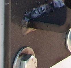
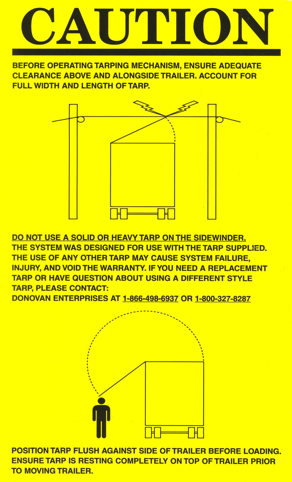
6 THESE INSTRUCTIONS SHOW THE SYSTEM BEING INSTALLED ON THE DRIVER SIDE OF THE TRAILER. FOLLOW THE SAME INSTRUCTIONS AND DIMENSIONS IF INSTALLATION IS TO BE ON THE PASSENGER SIDE. 1. PLACE ACTUATOR UNIT ON FRONT OF TRAILER AS SHOWN BELOW. USE THE (4) MOUNTING TABS AS A TEMPLATE, AND MARK THE HOLE LOCATION ON THE FRONT OF THE TRAILER (IF THE TRAILER IS STEEL, THE UNIT COULD BE WELDED INTO PLACE. NOTE: IF WELDING TO TRAILER USE EXTREME CAUTION TO AVOID GETTING WELD SPLAT- TER ON THE CHROME CYLINDER ROD. THIS WILL CAUSE PERMANENT DAMAGE TO THE CYLINDER AND VOID THE SYSTEMS WARRANTY). NOTE: THE ACTUATOR UNIT WEIGHS 134 lb (61 Kg). USE A OVER HEAD LIFTING DEVICE, AND SLING TO LIFT INTO MOUNTING LOCATION. PLACE SLING AROUND ENTIRE UNIT AT LOCATION MARKED LIFTING POINT IN DRAWING BELOW. 2. DRILL THE MARKED HOLE LOCATIONS TO ACCEPT 1/2 (1.3 cm) GRADE 5 (CLASS 8.8) OR BETTER BOLT (NOT SUPPLIED). 3. POSITION UNIT BACK INTO PLACE, AND SECURE USING 1/2 (1.3 cm) BOLTS MENTIONED IN STEP #2. NOTE: IF FRONT WALL OF TRAILER IS THIN ALUMINUM OR STEEL, USE SUFFICIENT BACKING PLATES INSIDE OF TRAILER TO SUPPORT THE UNIT. NOTE: IF TRAILER HAS A ROUND OR 45 deg FRONT CORNER YOU MUST SUPPORT THE FULL ACTUATOR UNIT. BRACE AND GUSSET BEHIND THE UNIT AS NECESSARY. 6
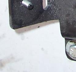
7 MOUNT THE FRONT HINGE AN 1-1/4 (3.18 cm) IN FRONT OF THE TRAILERS FRONT WALL AS SHOWN TO THE RIGHT. SOME TRAILERS HAVE A RIDGE OR LIP ON THE FRONT WALL. IF THIS IS THE CASE, TAKE YOUR 1 1/4 (3.18cm) MEASUREMENT FROM THE RIDGE AS SHOWN BELOW. NOTE: FRONT AND REAR HINGES ARE THE SAME PART, BUT ARE MOUNTED IN DIFFERENT LOCATIONS ON THE TRAILER. MOUNT REAR HINGE AS FAR TO THE REAR OF THE TRAILER AS POSSIBLE. IF THE TRAILER IS A TIPPER STYLE, MOUNT THE HINGE FORWARD TO MISS THE HINGE OF THE TAILGATE, THEN USE THE PLASTIC SHEET SUPPLIED TO COVER THE GAP (SEE PAGE 18 FOR PLASTIC SHEET INSTALLATION). NEXT STEP IS TO ASSEMBLE THE LIDS. THE FRONT LID IS SHOWN BELOW. ALL COMPONENTS FOR THE FRONT AND REAR LID ARE THE SAME WITH EXCEPTION OF THE 91 7/8 (233.36cm) I-BEAM. THIS I-BEAM FOR THE FRONT HAS HOLES THROUGH THE SIDE FOR MOUNTING THE ROLLER TRACK (SEE BELOW). FOLLOW THE NEXT (10) STEPS FOR THE ASSEMBLY OF THE FRONT LID. NOTE: DO NOT OVER TIGHTEN THE CARRIAGE BOLTS HOLDING THE LIDS TOGETHER. THIS COULD DAMAGE THE I-BEAMS. 7
8 ASSEMBLE THE (2) I- BEAMS SHOWN USING (2) REINFORCEMENT PLATES. NOTE: THE PLATES ARE OF DIFFERENT SIZE. IT DOES NOT MATTER WHICH PLATE IS ON TOP OR ON BOTTOM. USE (10) 1/4-20 x 2 1/2 (3.4mm x 64mm) CARRIAGE BOLTS, (10) 1/4 (3.4mm) WASHERS, (10) 1/4-20 (3.4mm) LOCK NUTS, AND (10) SPACERS AS SHOWN TO THE RIGHT. DO NOT TIGHTEN THESE CARRIAGE BOLTS UNTIL LATER. ASSEMBLE THE ANGLED TEE PLATES AND THE TEE PLATES TO THE I-BEAMS AS SHOWN USING (18) OF THE SAME SIZE CARRIAGE BOLTS, NUTS, WASHERS, AND SPACERS AS USED ABOVE. NOTE: THESE TEE PLATES ARE ALSO DIFFERENT SIZES. IT DOES NOT MATTER WHICH PLATE IS ON TOP OR THE BOTTOM. 8
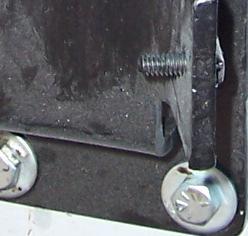
9 SLIDE THE SUPPORT TUBE OVER THE I-BEAM AND ALIGN THE HOLES ON THE ROLLER TRACK WITH THE HOLES ON BOTH THE SUPPORT TUBE AND I-BEAM. NEXT SECURE INTO PLACE USING (6) 5/16-18 x 3 (8mm x 75mm) FLAT HEAD SOCKET HEAD BOLTS WASHERS AND LOCK NUTS ATTACH THE HINGE BRACKETS AS SHOWN TO THE RIGHT USING A TOTAL OF (10) 1/4-20 x 2 1/2 (3.4mm x 64mm) CARRIAGE BOLTS, (10) 1/4 (3.4mm) WASHERS, (10) 1/4-20 (3.4mm) LOCK NUTS, AND (10) SPACERS. NOTE: THE CARRIAGE BOLTS MUST COME FROM THE BOTTOM ON THE HINGE BRACKETS AS SHOWN. ATTACH THE 28 1/4 (71.75cm) I-BEAM TO THE HINGE BRACKETS AS SHOWN USING (4) OF THE SAME CARRIAGE BOLTS, WASHERS AND LOCKNUTS USED ABOVE. DO NOT TIGHTEN UNTIL LATER. 9
10 ATTACH THE SUPPLIED PLASTIC PLATE TO THE I- BEAM ALIGNING THE BACK EDGES AS SHOWN, USING (5) SELF DRILLING SCREWS EQUALLY SPACED. THEN DRILL (3) 3/8 (10mm) HOLES THROUGH THE PLASTIC FOR ATTACHING THE TARP AT A LATER STAGE. ATTACH (3) STEEL LOOP STRAPS TO THE BACK OF THE TUBE SUPPORT BEHIND THE ROLLER TRACK, USING (3) SELF DRILLING SCREWS EQUALLY SPACED AS SHOWN TO THE RIGHT. NEXT STEP IS TO MEASURE THE WIDTH OF THE TRAILER ACROSS THE FRONT TOP RAILS. THIS DIMENSION MINUS 89 1/2 (227.3cm) EQUALS THE MEASUREMENT IN QUESTION TO THE RIGHT. EXAMPLE: IF YOUR TRAILER WIDTH IS 102 (259.0cm) YOU WOULD TAKE /2 = 12 1/2. THIS WOULD BE THE MEASUREMENT IN QUESTION TO THE RIGHT (259.0cm 227.3cm = 31.7cm) 10
11 NEXT STEP IS TO FASTEN THE LID EXTENSION AT THE MEASUREMENT CALCULATED FROM THE PREVIOUS STEP. FIRST DRILL (3) 3/8 (10mm) HOLES THROUGH THE SQUARE HOLES IN THE REINFORCEMENT PLATES AND LID EXTENSION. THEN USE (3) 3/8-16 x 3 (10mm x 75mm) CARRIAGE BOLTS, LOCK NUTS AND WASHERS. NOW TIGHTEN THE CARRIAGE BOLTS THAT HOLD THE REINFORCEMENT PLATES TO THE I-BEAMS. INSTALL THE EYE IN THE PRE DRILLED HOLE IN THE LID EXTENSIONS USING A 3/8 NUT, LOCK WASHER, WASHER AND LOC-TITE. THE ASSEMBLY OF THE FRONT LID IS NOW COMPLETE. ASSEMBLY OF THE REAR LID IS THE SAME AS THE FRONT LID EXCEPT THE REAR LID IS A MIRROR IMAGE (SEE TO THE RIGHT). THE REAR LID DOES NOT HAVE A ROLLER TRACK. 11


12 INSERT ROLLER AND SHAFT INTO ACTUATOR ARM AS SHOWN CAUTION!: AT THIS STAGE THE HYDRAULICS MUST BE INSTALLED, AND CYCLED TO ELIMINATE ANY AIR IN THE SYSTEM. FAILURE TO DO THIS COULD RESULT IN PERSONAL INJURY, AND/OR DAMAGE TO THE SYSTEM AT A LATER STAGE. HOLD THE PUMP MOUNT BRACKET IN PLACE AS A TEMPLATE ON THE FRONT OF THE TRAILER JUST BELOW THE ACTUATOR UNIT (APPROX 12, (30.5cm)). MARK THE LOCATION OF THE (4) HOLES, AND DRILL THROUGH TO EXCEPT 3/8 x 1 1/2 (.88cm x 3.81cm) LONG BOLTS PROVIDED. USE WASHERS AND 3/8 (.88cm) LOCK NUTS PROVIDED TO SECURE IN PLACE.. 12


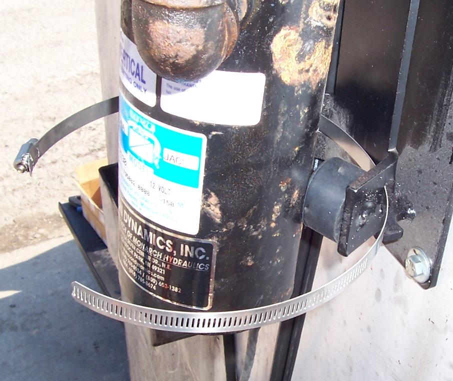


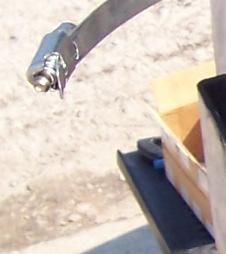


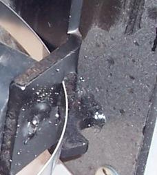
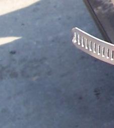
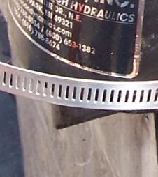


13 PLACE (4) RUBBER BUMPERS IN PLACE AS SHOWN AND SECURE PUMP BY USING 3/8-16 (.88cm) LOCK NUTS AND WASHERS. 3/8-16 (.88cm) LOCK NUT RUBBER BUMPERS SECURE BOTTOM OF PUMP USING LARGE HOSE CLAMP AS SHOWN CONNECT THE (2) HYDRAULIC HOSES TO THE PUMP AND CYLINDERS AS SHOWN. USE THE HOSE CLIPS AND SELF DRILLING SCREWS PROVIDED TO ORGANIZE AND SECURE THE HOSES. 13


 QUARTS (2.")

 TIMES TO")

 1 x 7 (25mm x 17.5cm) HINGE BOLTS, NUTS AND LOCK WASHERS.")
14 MOUNT CONTROL SWITCH AS SHOWN, WITH CABLE COMING FROM BOTTOM, USING (2) SELF DRILLING SCREWS PROVIDED. IMPORTANT: INSTALL THE CONTROL SWITCH IN AN AREA WHERE THE OPERATOR CAN SAFELY OBSERVE AND OPERATE THE SYSTEM. MOUNT THE QUICK DISCONNECT POWER CABLE NEAR THE CONTROL SWITCH SO THE OPERATOR HAS EASY ACCESS. USE THE HOSE CLIPS AND SELF DRILLING SCREWS PROVIDED TO ORGANIZE AND SECURE THE CABLES TO FRONT OF TRUCK. INSTALL ALL SAFETY STICKERS NEXT TO THE CONTROL SWITCH. SEE PAGE 17 FOR STICKER DESCRIPTION. REMOVE RED CAP FROM THE FILLER NECK ON PUMP, AND FILL PUMP WITH APPROXIMATELY (3) QUARTS (2.83 L) OF DEXTRON AUTOMATIC TRANSMISSION FLUID. REPLACE RED CAP WITH BLACK BREATHER CAP. NOTE: UNDER NORMAL OPERATING CONDITIONS THE FLUID IN THE HYDRAULIC PUMP WILL LAST THE LIFE OF THE PUMP. IN EXTREME DIRTY OR WET CONDITIONS, CHECK THE FLUID EVERY FOUR TO SIX MONTHS, AND CHANGE IF NECESSARY. CONNECT A 12V POWER SUPPLY TO THE QUICK DISCONNECT POWER CABLE, AND CYCLE THE CYLINDER (10) TIMES TO REMOVE ANY AIR IN THE SYSTEM. FAILURE TO DO THIS COULD RESULT IN PERSONAL INJURY, AND/OR DAMAGE TO THE SYSTEM AT A LATER STAGE. NEXT INSTALL THE FRONT LID AS SHOWN BELOW BY SLIDING THE ROLLER INTO THE ROLLER TRACK. THEN SECURE HINGES USING (2) 1 x 7 (25mm x 17.5cm) HINGE BOLTS, NUTS AND LOCK WASHERS. INSTALL THE REAR HINGE IN THE SAME MANNER, BUT WITHOUT THE ROLLER IN THE TRACK. NOTE: AT THIS POINT GREASE ALL (4) HINGES AT GREASE FITTINGS. 14
15 INSTALL THE CABLE THIMBLE TO THE FRONT HINGE CHAIN LINK AS SHOWN TO THE RIGHT. SLIDE THE CABLE THROUGH THE CABLE THIMBLE AND SECURE INTO PLACE USING (2) CABLE CLAMPS. USING SELF DRILLING SCREWS PROVIDED, ATTACH STEEL LOOP STRAPS ALONG THE TOP RAIL OF THE TRAILER ON THE HINGE SIDE EVERY 4 TO 5 FEET (122cm TO 152cm) DOWN TO THE REAR HINGE AS SHOWN TO THE RIGHT. NEXT, SLIDE THE CABLE THROUGH THE STEEL LOOP STRAPS BACK TO THE REAR HINGE. 15
16 OPEN THE ALUMINUM TURNBUCKLE AS LONG AS POSSIBLE, AND ATTACH TO THE CHAIN LINK ON THE REAR LID (ALUMINUM TURNBUCKLE MAY LOOK SLIGHTLY DIFFERENT THAN IN THE PICTURE). ATTACH THE OTHER END OF THE TURNBUCKLE TO THE CABLE USING (1) CABLE THIMBLE, AND (2) CABLE CLAMPS AS SHOWN TO THE RIGHT. TIGHTEN THE TURN BUCKLE TO TAKE UP ANY SLACK IN THE CABLE AND SECURE TURNBUCKLE THREADS WITH LOC-TITE PROVIDED. ATTACH THE (2) REMAINING CABLES TO THE REAR LID AS SHOWN USING (1) THIMBLE PER CABLE AND (2) CABLE CLAMPS PER CABLE. OPEN EACH STEEL TURNBUCKLE AS LONG AS POSSIBLE AND ATTACH ONE END TO THE FRONT LID AND THE OTHER END TO THE CABLES USING (1) THIMBLE PER CABLE AND (2) CABLE CLAMPS PER CABLE AS SHOWN TO THE LEFT. TIGHTEN EACH TURNBUCKLE TO TAKE THE SLACK OUT OF THE CABLES, THEN USE LOC-TITE ON THE THREADS TO LOCK IN PLACE. IMPORTANT: THE TOP CABLE IS USED TO HOLD MOST OF THE LOAD. THE BOTTOM CABLE IS USED TO KEEP THE TARP OVER THE TRAILER SIDE TO CREATE A SEAL. THE TOP CABLE MUST BE TIGHTENED MUCH MORE THAN THE BOTTOM CABLE. 16
17 IF THERE IS A GAP AT THE REAR OF THE TRAILER THE REAR PLASTIC FLAP WILL NEED TO BE INSTALLED ON THE REAR LID AS SHOWN BELOW. FIRST OPEN THE LID SO IT RESTS ON THE SIDE OF THE TRAILER. NEXT CUT THE FLAP TO LENGTH (APPROXIMATELY 2 (50mm) SHORTER THAN THE WIDTH OF THE TRAILER). CUT A NOTCH OUT OF THE FLAP TO MISS THE HINGE AS SHOWN BELOW. THEN ATTACH THE FLAP TO THE I-BEAM OF THE LID USING SELF DRILLING SCREWS EVERY 10 (25.0cm) DOWN THE LENGTH. DRILL A SERIES OF 3/8 (10mm) HOLES DOWN THE LENGTH EVERY 10 (25.0cm) AS SHOWN. THESE HOLES WILL ALLOW ZIP TIES TO BE USED TO ATTACH THE TARP TO THE REAR LID. 17
18 A REAR HOLD DOWN LATCH MUST BE INSTALLED TO KEEP THE REAR LID SECURE WHEN THE TRUCK IS IN MOTION. THERE ARE (4) TYPICAL INSTALLATION POSSIBILITIES FOR THE REAR LATCH. ALL FOUR ARE WELDED TOGETHER IN A SIMILAR MANNER. REVIEW ALL FOUR POSSIBILITIES BELOW TO DETERMINE THE BEST ARRANGEMENT FOR YOUR TRAILER. THE FIRST TWO OPTIONS SHOWN BELOW ARE BEST USED IF THE REAR LID IS MOUNTED FAR BACK TO THE REAR OF THE TRAILER. OPTION OPTION OPTIONS THREE AND FOUR SHOWN BELOW ARE BEST USED IF THERE IS A GAP BETWEEN THE REAR LID AND THE REAR WALL OF THE TRAILER. SEE THE NEXT PAGE FOR AN EXAMPLE OF AN INSTALLED HOLD DOWN LATCH. OPTION OPTION 18


19 BELOW ARE PICTURES OF AN INSTALLED REAR HOLD DOWN LATCH WITH A HOOK FOR REFERENCE. TIP: TACK WELD THE REAR HOLD DOWN LATCH TOGETHER FIRST TO CHECK OPERATION AND CLEARANCES BEFORE COMPLETELY WELDING HOOK MOUNTING BRACKET WITH SELF DRILLING SCREWS BUNGEE CORD CAUTION: OPERATOR MUST UNLATCH THE LID BEFORE SYSTEM IS ACTIVATED. 19
 AS SHOWN. (TARP IS SHOWN INSTALLED). NEXT ATTACH THE TARP TO THE UPPER CABLE USING A ZIP-TIE AT EVERY 8 to 12 (20cm to 30cm).")

 AS SHOWN.")
20 ATTACH THE TARP STARTING AT THE FRONT LID WORKING YOUR WAY TO THE BACK ON THE LOWER CABLE USING A ZIP-TIE AT EVERY 8 to 12 (20cm to 30cm) AS SHOWN. (TARP IS SHOWN INSTALLED). NEXT ATTACH THE TARP TO THE UPPER CABLE USING A ZIP-TIE AT EVERY 8 to 12 (20cm to 30cm). FRONT LID DISTANCE TO KEEP UPPER CABLE LOWER CABLE IMPORTANT: KEEP THE SAME DISTANCE AS SHOWN BETWEEN THE TWO CABLES DOWN THE LENGTH OF THE TRAILER. TILT THE LID TO THE POSITION SHOWN TO THE RIGHT, AND ATTACH THE TARP, STARTING FROM THE FRONT, TO THE FIXED CABLE ON THE HINGE SIDE USING ZIP TIES EVERY 8 to 12 (20cm to 30cm) AS SHOWN. FIXED CABLE STEEL LOOP STRAPS FRONT I-BEAM ATTACH THE TARP ALONG THE FRONT LID TO THE FRONT I-BEAM ONLY AS SHOWN TO THE LEFT. BEHIND THE ROLLER TRACK ATTACH THE TARP TO THE (3) STEEL LOOP STRAPS INSTALLED EARLIER. 20
 EXTRA MATERIAL.")


21 AT THE HINGES ATTACH THE TARP TO THE I-BEAM AND EYELET AS SHOWN TO THE RIGHT. I-BEAM FOR TRAILERS THAT ARE SHORTER THAN THE TARP LENGTH, CUT THE TARP AT EYELET THE BACK OF THE TRAILER, BUT LEAVE APPROX. 6 to 8 (15.2cm to 20.3cm) EXTRA MATERIAL. FOLD OVER THE EXCESS MATERIAL, AND ZIP TIE ALONG REAR I-BEAM ONLY ON THE REAR LID. IF THE PLASTIC REAR FLAP IS USED, ZIP TIE THE TARP AROUND THE I-BEAM THROUGH THE HOLES DRILLED IN THE FLAP EARLIER. TIP: IF THERE IS A SMALL GAP BETWEEN THE REAR LID, AND THE TRAILER REAR DOOR, DO NOT CUT THE EXCESS TARP MATERIAL. ROLL THE EXCESS TARP MATERIAL UP AND ZIP-TIE IT TO THE REAR I-BEAM TO HELP COVER THE GAP. NOTE: 2 (5cm) WIDE SPLICING TAPE IS SUPPLIED, AND CAN BE USED TO PROTECT THE TARP BY WRAPPING A SMALL LENGTH AROUND ANY SHARP POINTS ON THE SYSTEM. PLASTIC FLAP REAR I-BEAM IF THE TRAILER IS EQUIPPED WITH A CENTER CROSS BRACE, INSTALL THE BLACK MESH MATERIAL PROVIDED TO THE UNDERSIDE OF THE TARP TO PROTECT THE TARP. USE EXTRA ZIP TIES TO ATTACH THE BLACK MESH TO THE CABLES ONLY. NOTE: DO NOT ZIP TIE THE BLACK MESH TO ORANGE TARP. BLACK MESH CABLE CABLE 21
22 INSTALL THE WIND DEFLECTOR OVER THE HYDRAULIC UNIT USING (6) STAINLESS STEEL BUTTON HEAD BOLTS, (3) AT 3 (7.6cm) AND (3) AT 2 (5cm). USE THE LARGE WIND DEFLECTOR BRACKET ON THE LEFT, AND THE SMALL WIND DEFLECTOR BRACKET ON THE RIGHT AS SHOWN BELOW (OPPOSITE IF THE INSTALL IS ON THE PASSENGER SIDE. USE THE LOC-TITE PROVIDED ON THE (1) MIDDLE BOLT SHOWN, AND LOCK NUTS ON THE (5) REMAINING BOLTS PERIODIC MAINTENANCE and INSPECTION: -Daily: 1. Check mechanism for any damage or cracks. 2. Check tarp for excessive wear and tear. 3. If equipped, check electrical cables for insulation damage. 4. Check hoses and fittings for cracks and leaks. 5. Check tarp cable and adjust if loose. - Weekly: 1. Check cylinders for leaks or excessive wear. 2. Check tightness of the fasteners. 3. Check hinges for excessive wear. 4. Check hydraulic actuator for any cracks, damage or excessive wear. 5. If equipped, check the hydraulic fluid level in hydraulic pump. - Monthly: 1. Operate system to verify proper safe operation. 2. Check roller trolley and bearing for damage in front lid. 3. Grease the hinges. 22
23 OPERATING INSTRUCTIONS CAUTION: BEFORE OPERATING THIS OR ANY TARPER, CHECK YOUR SURROUNDINGS. LOOK FOR OVERHEAD POWER LINES, TREE LIMBS, ETC.. DO NOT OPERATE SYSTEM WHEN DANGER OF LIGHTNING STRIKE IS PRESENT. CAUTION: When servicing or repairing the Sidewinder II system, disconnect power to the components from the vehicles battery. NOTE: The noise level is less than 72dB(A) TO OPEN TARP PRESS UP ON SWITCH LEVER TO OPEN LID. DON T FORGET TO RELEASE THE REAR LATCH TO CLOSE TARP PRESS DOWN ON SWITCH LEVER TO CLOSE LID. DON T FORGET TO ENGAGE THE REAR LATCH 23


24 SAFETY STICKERS 24
25 SIDEWINDER WET KIT 1. CONNECT T FITTING TO HYDRAULIC RETURN LINE. 2. CONNECT PRIORITY FLOW CONTROL VALVE TO HYDRAULIC SUPPLY LINE. 3. ATTACH HANDLE TO FRONT OF TRAILER IN A SUITABLE LOCATION FOR OPERATION. 4. HOOK UP 9 HYDRAULIC HOSE TO THE TRAILER S CENTER-MOST HYDRAULIC CYLINDER FITTING. 5. HOOK UP 8 HYDRAULIC HOSE TO THE TRAILER S OUTER-MOST HYDRAULIC CYLINDER FITTING. 6. WITH HYDRAULICS BEING SUPPLIED TO PRIORITY FLOW CONTROL VALVE, CYCLE HAND VALVE BACK AND FORTH 3 TO 4 TIMES TO PURGE ANY AIR FROM HYDRAULIC LINES. T FITTING HYDRAULIC RETURN LINE FROM TRAILER PRIORITY FLOW CONTROL VALVE HYDRAULIC PRESSURE LINE FROM TRAILER HYDRAULIC RETURN LINE FROM TRUCK S TANK HYDRAULIC PRESSURE LINE TO TRAILER 9 HYDRAULIC HOSE TO CENTER-MOST HYDRAULIC FITTING 8 HYDRAULIC HOSE TO OUTER-MOST HYDRAULIC FITTING 25
26 SIDEWINDER WET KIT PARTS BREAKDOWN CONTROL VALVE P/N:1614 REDUCER 1 NPTM to 1/4 NPTF P/N: MALE BRANCH TEE FLOW DIVIDER (PRI FLOW CONTROL) 1 GPM P/N:2641 1/4 NPTM to #4JICM 90deg P/N:572 #4 JICM to #8 ORBM 90deg P/N:1061 #4 JICM to #8 ORBM 90deg P/N:1061 1/4 NPTM to 1/4 NPTF 90deg P/N:1610 1/4 NPTM to 1/4 JICM P/N:2960 CONTROL VALVE P/N:1614 1/4 NPT to 1/4 NPT HEX NIPPLE P/N:1622 FLOW CONTROL P/N:2533 REDUCER #8 SAE ORBM to 1/4 NPTF P/N:1613 1/4 NPTM to 1/4 NPTM 90deg P/N:
27 9 HOSE w/ both ends #4 JICF P/N: HOSE w/ both ends #4 JICF P/N: HOSE w/ both ends #4 JICF P/N: HOSE w/ both ends #4 JICF P/N:
LIFT N LOAD INSTALLATION, MAINTENANCE, & SAFETY INSTRUCTIONS (800)
") LIFT N LOAD INSTALLATION, MAINTENANCE, & SAFETY INSTRUCTIONS (800) 272-6276 001-321-757-7611 www.cramarotarps.com Plants In: Delaware, Florida, Massachusetts, Nevada, Ohio, and Canada General Information
LIFT N LOAD INSTALLATION, MAINTENANCE, & SAFETY INSTRUCTIONS (800) 272-6276 001-321-757-7611 www.cramarotarps.com Plants In: Delaware, Florida, Massachusetts, Nevada, Ohio, and Canada General Information
2000SR. Installation Instructions May Donovan Enterprises 3353 S.E. Gran Park Way Stuart, Florida
 311499-Donovan 4/28/04 11:22 PM Page 1 Installation Instructions May 2003 Donovan Enterprises 3353 S.E. Gran Park Way Stuart, Florida 34997 1-800-327-8287 Visit our web site at: www.donovan-ent.com 311499-Donovan
Installation Instructions February 2009
 Installation Instructions February 2009 www.donovan-ent.com Donovan Enterprises 3353 SE Gran Park Way Stuart, FL 34997 800-327-8287 The Hammer Head Assembly Installation Instructions (Rollerbar & Direct
Installation Instructions Models 2858, 2858A-1, 2858GL February 2009
 Installation Instructions Models 2858, 2858A-1, 2858GL February 2009 www.donovan-ent.com Donovan Enterprises 3353 SE Gran Park Way Stuart, FL 34997 800-327-8287 Step 1 Head Assembly Installation Instructions
Website: ELIMINATOR MD. (701) (800)
 (800)") Website: www.tbei.com E-mail: sales@tbei.com ELIMINATOR MD www.rugbymfg.com sales@rugbymfg.com (701) 776-5722 (800) 533-0494 1228633 1 DATE PURCHASED BODY SERIAL NUMBER HOIST SERIAL NUMBER CYLINDER SERIAL
Website: www.tbei.com E-mail: sales@tbei.com ELIMINATOR MD www.rugbymfg.com sales@rugbymfg.com (701) 776-5722 (800) 533-0494 1228633 1 DATE PURCHASED BODY SERIAL NUMBER HOIST SERIAL NUMBER CYLINDER SERIAL
Installation Instructions. Attention Dealers: Please give this owners manual to the customer when the product is delivered.
 Serving the Truck & Trailer Industry Since 1944 Attention Dealers: Please give this owners manual to the customer when the product is delivered. Call 800-535-9545 www.aeroindustries.com Indianapolis, IN
table of Contents Warranty:
 table of Contents placement of the Mounting Bolts spudnik swingout... 2 spudnik solid... 2 logan swingout... 3 logan solid... 3 double l swingout... 4 double l solid... 4 Mounting Framework... 5-6 Mounting
Easy Cover. Installation Instructions. Attention Dealers: Please give this owners manual to the customer when the product is delivered.
 Serving the Truck & Trailer Industry Since 944 Easy Cover Attention Dealers: Please give this owners manual to the customer when the product is delivered. Call 00-3-94 www.aeroindustries.com Indianapolis,
GRAIN CART TARP SYSTEM INSTALLATION AND OPERATION MANUAL
 GRAIN CART TARP SYSTEM INSTALLATION AND OPERATION MANUAL Grain Carts KITS Thunderstone Manufacturing, LLC. 3400 West O Street Lincoln, NE 68528 402-435-4249 (Fax) 402-438-3918 www.thunderstonemfg.com Aluminum
CRYSTEEL S HOIST. this manual must be included with the vehicle after completing the installation.
 Website: www.tbei.com E-mail: sales@tbei.com CRYSTEEL S STINGRAY HOIST this manual must be included with the vehicle after completing the installation. Web Site E-Mail Phone (507) 726-2728 www.crysteel.com
MODEL NO & UP MODEL NO & UP MODEL NO & UP MODEL NO & UP MODEL NO.
 9-0688 MODEL NO. 00-800 & UP MODEL NO. 0-800 & UP MODEL NO. 5-800 & UP MODEL NO. -800 & UP MODEL NO. 0-800 & UP SKID SPRAYER with the Centrifugal Pump FORM NO. 95-9095 SET-UP AND PARTS CATALOG SAFETY AND
MODEL NO & UP MODEL NO & UP MODEL NO & UP MODEL NO & UP MODEL NO.
 9-0688 MODEL NO. 00-800 & UP MODEL NO. 0-800 & UP MODEL NO. 5-800 & UP MODEL NO. -800 & UP MODEL NO. 0-800 & UP SKID SPRAYER with the Diaphragm Pump FORM NO. 95-90 SET-UP AND PARTS CATALOG SAFETY AND INSTRUCTION
INSTALLATION, MAINTENANCE, & SAFETY INSTRUCTIONS
 Tarpaulin Systems Flip -N- Go / Quick Mount Flip -N- Go System INSTALLATION, MAINTENANCE, & SAFETY INSTRUCTIONS (800) CRAMARO (800) 272-6276 Plants In: Delaware, Florida, Massachusetts, Nevada, Ohio Install
CRYSTEEL S. this manual must be included with the vehicle after completing the installation.
 Website: www.tbei.com E-mail: sales@tbei.com CRYSTEEL S POWER TAILGATE this manual must be included with the vehicle after completing the installation. Web Site E-Mail Phone (507) 726-2728 www.crysteel.com
SERVICE MANUAL / PARTS LIST
 SERVICE MANUAL / PARTS LIST MARK 55 PUSH PULL CONTENTS: PAGE 1 Lift Truck Requirements General Installation Procedures General Inspection 2-3 Base Assembly 4 Linkage Assembly 5 Platen Assembly 6 Jaw /
5000 Series Covering Systems Installation Instructions
 ENTERPRISES Donovan R a I s e T h e S t a n d a r d 5000 Series Covering Systems Installation Instructions The following hardware is universal to all kits: Bent arm extension (L) 1 905 Hose clamp 1 ½ 4
Assembly Instructions
 Assembly Instructions Part Number Description Model Approx. Assembly Time 99994-049 Cab Enclosure MULE SX 3-4 Hours WARNING Improper installation of this accessory could result in an accident causing serious
Combine Cover Manual
 Combine Cover Manual Installation Instructions Page 27 Operating Instructions Page 8 Warranty Page 8 Trouble Shooting Page 9 11 For Model s: Case I.H. 2388, 2188, 1688 and 1680 With a MAURER Hopper Extension
Installation Instructions
 Installation Instructions ELECTRIC CONVERSION KIT 3 ALUMINUM ROLL TUBE IMPORTANT: This Electric Conversion Kit has been designed for systems with a 3 aluminum roll tube. It is assumed that the tarping
WARNING: the engine does not come with oil in it. Please fill the oil before starting. The 200cc hardknock requires 9/10 of a quart of oil.
 WARNING: the engine does not come with oil in it. Please fill the oil before starting. The 200cc hardknock requires 9/10 of a quart of oil. Things needed for assembly. -2 tubes of blue loc-tite. I don
400 SERIES HYDRA-LIFT KARRIERS
 OPERATOR S MANUAL FOR HYDRA-LIFT DRUM KARRIERS - Serial # 0802 to (MMYY) The letter A in the model number indicates that the unit is for 55 gallon standard steel drum ( 22½ diameter). Model Dispensing
MODEL 400A-60 & 400Z-72 HYDRA-LIFT KARRIERS
 OPERATOR S MANUAL FOR 400Z SERIES MANUAL TILT S The letter Z in the model number indicates that the unit is for 55 gallon standard steel drum ( 22.5 diameter) and accepts attachments to handle a 55 gallon
LORON SERVICE MANUAL / PARTS LIST. DEDICATED PUSH PULL B Style
 LORON SERVICE MANUAL / PARTS LIST DEDICATED PUSH PULL B Style CONTENTS: Page 1... Lift Truck Requirements General Installation Procedures General Weekly Inspection 2... Major Push Pull Parts Bushing Group
C-10 INSTALLATION INSTRUCTIONS
 GROSS LOAD CAPACITY WHEN USED AS A WEIGHT CARRYING HITCH: 30,000 LBS. TRAILER WEIGHT & 6,000 LBS. TONGUE WEIGHT. ***DO NOT EXCEED VEHICLE MANUFACTURER'S RECOMMENDED TOWING CAPACITY.*** Parts List ITEM
Combine Cover Manual
 Combine Cover Manual Installation Instructions Page 26 Operating Instructions Page 7 Warranty Page 7 Trouble Shooting Page 8 10 For Big Top Extension Model s: Case I.H. 8010, 8120 Please forward onto Customer
INSTALLATION & OWNER S MANUAL
 Rev. C p. 1 of 21 INSTALLATION & OWNER S MANUAL F5205 HARD SIDED CAB KIT INSTALLATION & OWNER S MANUAL The contents of this envelope are the property of the owner. Be sure to leave with the owner when
Parts Manual FRONT-FOLD BOOMS MODELS 80, 90 & 100 HYDRAULIC FOR TA1200 & TA1600 SPRAYERS. Serial Number B & Higher. Part No.
 Parts Manual FRONT-FOLD BOOMS MODELS 80, 90 & 100 HYDRAULIC FOR TA1200 & TA1600 SPRAYERS Serial Number B30970200 & Higher Part No. 408920 Front-Fold Booms 80 / 90 / 100 Introduction Foreward This symbol
JEEVES. JEEVES Installation Manual. Installation Manual The Easiest Do-It-Yourself Dumbwaiter on the Market
 1 888-323-8755 www.nwlifts.com JEEVES Installation Manual The Easiest Do-It-Yourself Dumbwaiter on the Market This manual will cover the installation procedure step-by-step. The installation of this dumbwaiter
SWING DOOR SOFT ENCLOSURE (part# 16733)
") 800-643-7332 americanlandmaster.com This kit is for use with all fullsize, 2 passenger ALM utility vehicles. SWING DOOR SOFT ENCLOSURE (part# 16733) NOTE TOOLS REQUIRED Drill 1/4 Drill Bit 7/16 Wrench
800-643-7332 americanlandmaster.com This kit is for use with all fullsize, 2 passenger ALM utility vehicles. SWING DOOR SOFT ENCLOSURE (part# 16733) NOTE TOOLS REQUIRED Drill 1/4 Drill Bit 7/16 Wrench
EASY DUMP RD3100 / RD3106 (Standard)-(60/40 Split)-(60/40 Divider)- (70/30 Split with Bayne) USER S MANUAL
-(60/40 Split)-(60/40 Divider)- (70/30 Split with Bayne) USER S MANUAL") EASY DUMP RD3100 / RD3106 (Standard)-(60/40 Split)-(60/40 Divider)- (70/30 Split with Bayne) USER S MANUAL *** Important *** Read User s Manual Completely Prior to Operating Par-Kan Company Phone: 1-800-291-5487
EASY DUMP RD3100 / RD3106 (Standard)-(60/40 Split)-(60/40 Divider)- (70/30 Split with Bayne) USER S MANUAL *** Important *** Read User s Manual Completely Prior to Operating Par-Kan Company Phone: 1-800-291-5487
KMW Parts List
 08/ PART NUMBER DESCRIPTION LIST PRICE 0595-3084 Decal Warning $5.28 0595-3001 Decal Warning $1.92 0595-3002 Decal Danger $2.28 0595-3003 Decal Warning $2.16 0595-3004 Decal Warning $2.04 0595-3178 Decal
Universal Super Shield & Ultimate Aluminum w/electric Drive Conversion Kits , , Installation Instructions
 WLH 09/19/16 111-0215 & 112-0215 607-0026 For technical support call us at (800) 368-3075 or visit our website at PullTarps.com. TABLE OF CONTENTS ***Assembly*** Conversion Kit-Universal Super Shield ***Wiring,
Liftgate Terminology
 SL-20 Series SL-20 Series Click the appropriate link below for the major component of the liftgate for which you are trying to find the correct part. If you are unsure of the name of the part in Waltco
INSTALLATION INSTRUCTIONS 97 FORD EXPEDITION
 INSTALLATION INSTRUCTIONS 97 FORD EXPEDITION 1. Read the instructions completely and carefully before you begin. Check the kit for proper contents (refer to the part s list and the picture diagrams). Before
Fold Hydraulics Item Qty Part No. Description
 Fold Hydraulics 1 2 465385 Quick Coupler 3/4"-16 FOR 2 2 469882 Hose ½" x 468" (3/4 FJSw x 3/4 MOR) 3 2 469833 Hose ½" x 87" (3/4 FJSw) 4 4 465310 Adapter 90 (3/4 MOR x 3/4 JICM) 5 2 469866 Hose ½" x 230"
SECTION V ASSEMBLY CAUTION THE FOLLOWING SAFETY PRECAUTIONS SHOULD BE THOROUGHLY UNDERSTOOD BEFORE ATTEMPTING MACHINE ASSEMBLY.
 SECTION V ASSEMBLY CAUTION THE FOLLOWING SAFETY PRECAUTIONS SHOULD BE THOROUGHLY UNDERSTOOD BEFORE ATTEMPTING MACHINE ASSEMBLY. 1. Wear personal protective equipment such as, but not limited to protection
JODALE PERRY. Parts List & Mounting Instructions. Jacobsen HR9016 JDP BUILT FOR LIFE
 JODALE PERRY Parts List & Mounting Instructions Jacobsen HR9016 JDP BUILT FOR LIFE Jacobsen HR9016 Mounting Instructions Standard Parts 1 - LH Rear Mounting Bracket 1 - RH Rear Mounting Bracket 1 - Front
INSTALLATION MANUAL HYDRAULIC HOSE REEL
 INSTALLATION MANUAL HYDRAULIC HOSE REEL 1 TABLE OF CONTENTS SECTION PAGE SECTION PAGE 1 HOW TO ORDER PARTS 3 MAINTENANCE SCHEDULE... 11 1.1 HOW TO ORDER PARTS... 2 1.2 MODEL IDENTIFICATION... 3 2 INSTALLATION
Illustrated Parts & Packing List 528 Gandrud Road, Owatonna, MN For a complete distributor & dealer list go to
 Illustrated Parts & Packing List 528 Gandrud Road, Owatonna, MN 55060 For a complete distributor & dealer list go to www.gandy.net 66GW27F Orbit-Air Applicator 120 Cu. Ft. Hopper w/ 27 (2 ) Openings, Fertilizer
M:\Logo.jpg SERVICE MANUAL / PARTS LIST APPLIANCE CLAMP SOFT TOUCH
 M:\Logo.jpg SERVICE MANUAL / PARTS LIST APPLIANCE CLAMP SOFT TOUCH MODEL #113644 PATENT NO. 9,630,821 CONTENT: PAGE 1 Lift Truck Requirements General Installation Procedures General Inspection & Maintenance
CHAIN & HOOKS. Proof Coil Chain Grade 28. Transport Chain Grade 70
 Proof Coil Chain Grade 28 Proof coil chain is suitable for use as towing chain, logging,fencing, trailer safety chain, boat anchors, security barriers or other general purposes where chain of high tensile
Lifting height 5.5" - 72" with adapters " Height overall 165" Width between columns 122" Drive through 109" Width overall 151.
 Model Number TP12KC-D Capacity 12,000 lbs. Lifting height 5.5" - 72" with adapters 79.625" Height overall 165" Width between columns 122" Drive through 109" Width overall 151.125" Arm extension 37.5" -
Patriot. Aluminum and Steel 5spring. Step #1 Tarp Spool with Gear Motor (Includes Instructions for Optional Wind Deflector)
") Aluminum and Steel 5spring Qty. Component Parts Description: LONG BOX: (1) 103 Aluminum Tarp Axle (2) 98 Upper Arms with 90 Degree Elbow (2) Lower Aluminum ( 84 ) (1) Aluminum Cross Tube SMALL HARDWARE
Aluminum and Steel 5spring Qty. Component Parts Description: LONG BOX: (1) 103 Aluminum Tarp Axle (2) 98 Upper Arms with 90 Degree Elbow (2) Lower Aluminum ( 84 ) (1) Aluminum Cross Tube SMALL HARDWARE
CHEVY/GMC /2-TON PICKUP 3 BODY LIFT INSTALLATION INSTRUCTIONS 2006 KIT# PA10163 MANUAL TRANSMISSION VEHICLES REQUIRE KIT# PA4701
 3651 N Highway 89 Chino Valley, AZ 86323 (928) 636-7080 www.p-a-g.net CHEVY/GMC 1500 1/2-TON PICKUP 3 BODY LIFT INSTALLATION INSTRUCTIONS 2006 KIT# PA10163 MANUAL TRANSMISSION VEHICLES REQUIRE KIT# PA4701
READ AND UNDERSTAND ALL INSTRUCTIONS AND WARNINGS PRIOR TO INSTALLATION OF SYSTEM AND OPERATION OF VEHICLE.
 #9378 Installation Instructions 3 Body Lift Kit 1998-2000 Ranger READ AND UNDERSTAND ALL INSTRUCTIONS AND WARNINGS PRIOR TO INSTALLATION OF SYSTEM AND OPERATION OF VEHICLE. SAFETY WARNING BDS Suspension
EURO REEL
 Date Purchased Machine Serial No. Options The key number system in this parts book is arranged as follows: Please order parts by number - Key numbers with two circles denotes main assemblies. - Key numbers
Part Name/Description Part Number Quantity Instruction Kit Metalfor Flow Sensor
 NOTE: Indented items indicate parts included in an assembly listed above Part Name/Description Part Number Quantity Instruction Kit Metalfor 4101091 1 Flow Sensor 4001356 1 Deflector plate 2000612-1 1
INSTALLATION INSTRUCTIONS
 INSTALLATION INSTRUCTIONS Thank you for purchasing an AUTOLOCK Electric Tarp. ACI proudly manufactured this product using superior quality materials and workmanship. With proper care, your tarp will provide
MARATHON TELESCOPIC HOIST
 Website: www.tbei.com E-mail: sales@tbei.com CRYSTEEL S MARATHON TELESCOPIC HOIST this manual must be included with the vehicle after completing the installation. Web Site E-Mail Phone (507) 726-2728 www.crysteel.com
PFadvantage Metalfor Araus 1360
 Metalfor Araus 1360 Note: Indented items indicate parts included in an assembly listed above Part Name/Description Part Number Quantity Instruction Kit Metalfor Araus 2005300-14 1 Display Bracket 4000134
ACCLAIM OPERATOR, PARTS, AND INSTALLATION MANUAL BX4330 ACCLAIM
 ACCLAIM OPERATOR, PARTS, AND INSTALLATION MANUAL BX4330 ACCLAIM Tow Bar Class III (5000 lb) 2 Inch Coupler TOWING PRODUCTS DIVISION Page 1 of 8 292-2205 4/23/09 SAFETY DO NOT INSTALL, OPERATE OR USE THIS
FRONT-FOLD BOOMS MODELS 80, 90 & 100 HYDRAULIC
 FRONT-FOLD BOOMS MODELS 80, 90 & 100 HYDRAULIC FOR TA1200, TA1600 & TA2400 SPRAYERS Serial Number B26720100 & Higher Part No. 407525 Front-Fold Booms 80 / 90 / 100 Introduction Foreward This symbol identifies
INSTRUCTIONS, (FORD) SUPER DUTY INSTALLATION KIT (C2 PICKUP LIFTGATES)
 SUPER DUTY INSTALLATION KIT (C2 PICKUP LIFTGATES)") LIFT CORPORATION Sht. 1 of 22 DSG# M-16-32 Rev. - Date: 12/13/16 INSTRUCTIONS, (FORD) SUPER DUTY INSTALLATION KIT (C2 PICKUP LIFTGATES) FORD SUPER DUTY F-250, F-350 & F-450 PICKUP TRUCKS, 2017 MODEL KIT
LIFT CORPORATION Sht. 1 of 22 DSG# M-16-32 Rev. - Date: 12/13/16 INSTRUCTIONS, (FORD) SUPER DUTY INSTALLATION KIT (C2 PICKUP LIFTGATES) FORD SUPER DUTY F-250, F-350 & F-450 PICKUP TRUCKS, 2017 MODEL KIT
INSTALLATION INSTRUCTIONS AND OWNER S MANUAL
 INSTALLATION INSTRUCTIONS AND OWNER S MANUAL Thank you for purchasing the AlloyCover from WeatherTech. Manufactured with pride using superior quality materials and workmanship. With proper care, your cover
Collection System. Please read the operator s manual carefully and make sure you understand the instructions before using the machine.
 Collection System 967004601 Please read the operator s manual carefully and make sure you understand the instructions before using the machine. 2012 All rights reserved. Swainsboro, GA. Printed in U.S.A.
Type 2 Push-Through 37 Ton Log Splitter. Assembly Manual
 Type 2 Push-Through 37 Ton Log Splitter Assembly Manual Refer to this manual for the following models: RS37PT-LF09PC-16-1 RS37PT-LF09EC-16-1 RS37PT-LF09EC-16-2 RS37PT-LF13EC-22-1 RS37PT-LF13EC-22-2 RS37PT-LF15EC-22-1
INSTALLATION INSTRUCTIONS
 INSTALLATION INSTRUCTIONS For 63600 and 64040 Front Bumper and Winch Mount For Ford Super Duty Trucks As you read these instructions, you may see NOTES, CAUTIONS and WARNINGS. Each message has a specific
INSTALLATION INSTRUCTIONS
 INSTALLATION INSTRUCTIONS OUTLAW REAR BUMPER APPLICATION: 2016-2018 Chevrolet Silverado 1500 PART NUMBER: 58-81005 CONTENT ITEM QUANTITY DESCRIPTION TOOLS NEEDED 1 1 REAR BUMPER 18MM WRENCH 2 4 SENSOR
<THESE INSTRUCTIONS MUST BE GIVEN TO THE END USER> B&W
 B&W Trailer Hitches 6 Hawaii Rd / PO Box 86 Humboldt, KS 66748 P:60.473664 F:60.869.903 Turnoverball Gooseneck Hitch Installation Instructions MODEL 08
INSTALLATION & OWNER S MANUAL
 INSTALLATION & OWNER S MANUAL CAB INSTALLATION INSTRUCTIONS JOHN DEERE 3000 SERIES (4200/4300/4400) (4210/4310/4410) & (3120/3320/3520/3720) HARD SIDED CAB ENCLOSURE (p/n 1JD3520AS) SOFT SIDED CAB ENCLOSURE
OWNER S MANUAL Kellen Gross Dr., Yankton SD Phone: TRUXEDO ( ) Fax: (605) Web Site:
 Fax: (605) Web Site:") Owner s & Installation Manual READ INSTRUCTIONS - Failure to assemble cover properly will void warranty. OWNER S MANUAL Damaged or missing parts? Call 1-877-878-9336 Mon - Fri 8 am - 5 pm CT Parts will
Owner s & Installation Manual READ INSTRUCTIONS - Failure to assemble cover properly will void warranty. OWNER S MANUAL Damaged or missing parts? Call 1-877-878-9336 Mon - Fri 8 am - 5 pm CT Parts will
INSTALLATION & OWNER S MANUAL
 INSTALLATION & OWNER S MANUAL CAB INSTALLATION INSTRUCTIONS JOHN DEERE 4000 SERIES (4500/4600/4700) (4510/4610/4710) (4120/4320/4520/4720) HARD SIDED CAB ENCLOSURE (p/n 1JD4120AS) SOFT SIDED CAB ENCLOSURE
Ag Leader Technology. Parts List for Combine MF , 8780, White 9700
 Parts List for Combine Quantity by Model Note: Indented items indicate parts included W in an assembly listed above 8 8 8 8 H 5 5 5 7 I 6 7 9 8 T Part Name/Description Part No. 0 0 0 0 E Instruction Kit
A B C D E F. Tools Required (supplied by others)
") Page 1 of 17 Parts List Below Deck Automatic Retractable Security Cover Kit (1) Tube End Bearing Plate (A) (1) Rope Reel and Cover Drum Motor Assembly (B) (1) Cover Drum (1) Pulley Support Channel (2)
Page 1 of 17 Parts List Below Deck Automatic Retractable Security Cover Kit (1) Tube End Bearing Plate (A) (1) Rope Reel and Cover Drum Motor Assembly (B) (1) Cover Drum (1) Pulley Support Channel (2)
8 PARTS MANUAL 8.1 LIFT ASSEMBLY
 8 PARTS MANUAL 8.1 LIFT ASSEMBLY 19 8.2 LIFT ASSEMBLY PARTS LIST ITEM QTY DESCRIPTION PART # 1 1 TOWER WELDMENT, POWER SIDE 4-0767 2 2 CARRIAGE WELDMENT 4-0778 3 8 GLIDE BEARING 2-0772 4 4 GREASE NIPPLE
INSTALLATION & OWNER S MANUAL
 INDUSTRIES, LLC. INSTALLATION & OWNER S MANUAL CAB INSTALLATION INSTRUCTIONS KUBOTA GRAND L 40 SERIES HARD SIDED CAB ENCLOSURE (p/n 1KGL4AS) This Curtis Cab is designed and manufactured for use only as
A1062 & A1072 AUGER ASSEMBLY MANUAL. Read & understand all instructions pertaining to this auger prior to use!
 A1062 & A1072 AUGER ASSEMBLY MANUAL Read & understand all instructions pertaining to this auger prior to use! Safety Alert Watch for this ALERT Symbol. It identifies potential hazards to Personal SAFETY
8 PARTS MANUAL 8.1 LIFT ASSEMBLY
 8 PARTS MANUAL 8.1 LIFT ASSEMBLY 19 8.2 LIFT ASSEMBLY PARTS LIST ITEM QTY DESCRIPTION PART # 1 1 TOWER WELDMENT, POWER SIDE 4-1010 2 2 CARRIAGE WELDMENT 4-1114 3 8 GLIDE BEARING 2-0772 4 4 GREASE NIPPLE
250P Manure Spreader
 0P Manure Spreader Illustrated Parts Breakdown Page - Page Page Page Page Page Page Page Page Page Page Page Page Page Page - Page Page Page 0 Complete Front End PTO/Jack/Hitch Assembly Front Pulley Assembly
OPERATOR S MANUAL MAINTENANCE MANUAL PARTS LIST TURFCO CR-7. Broadcast Top Dresser. Product Number Starting Serial Number P00851
 OPERATOR S MANUAL MAINTENANCE MANUAL PARTS LIST TURFCO CR- Broadcast Top Dresser Product Number 0 Starting Serial Number P00 US Patent,,0,,0, and,, Manual Number DANGER - IF INCORRECTLY USED THIS MACHINE
SAFETY SAFETY CABLE INSTALLATION /00 1 of 6
 SAFETY DO NOT INSTALL, OPERATE OR USE THIS EQUIPMENT UNTIL THE FOLLOWING OPERATING AND SAFETY INSTRUCTIONS HAVE BEEN READ AND UNDERSTOOD. This symbol is used to bring attention to safety precautions and
INSTALLATION INSTRUCTIONS
 INSTALLATION INSTRUCTIONS OUTLAW REAR BUMPER APPLICATION: 2013-2018 Dodge Ram 1500 PART NUMBER: 58-81025 CONTENT ITEM QUANTITY DESCRIPTION TOOLS NEEDED 1 1 REAR BUMPER 18MM WRENCH 2 4 SENSOR L-TAB 5MM
INSTALLATION INSTRUCTIONS
 INSTALLATION INSTRUCTIONS HD BUMPER Kit 66240 (BLACK), 74760 (BLACK) & 74690 TUBELESS (TEXTURED BLK) For 03-Newer Chevy 3/4 Ton Trucks As you read these instructions, you will see NOTES, CAUTIONS and WARNINGS.
PFadvantage MF 6850/6855; Ideal 9080/9090
 MF 6850/6855; Ideal 9080/9090 Note: Indented items indicate parts included in an Quantity by Model assembly listed above MF Ideal Part Name/Description Part Number 6850 6855 9080 9090 Instruction Kit MF
East Manufacturing Corporation
 East Manufacturing Corporation www.eastmfg.com Volume revised 0/ ef EAST HARDWARE TABLE OF CONTENTS CATEGORY PAGE NO ALUMINUM TAILGATE HARDWARE 3 HOIST & ALUM. BULKHEAD HARDWARE 7 BODY HARDWARE 8 HARDWARE
WARNING WARNING CAUTION. Warnings and Cautions MOVING PARTS ENTANGLEMENT HAZARD MOVING PARTS ENTANGLEMENT HAZARD CHEMICAL AND FIRE HAZARD
 Warnings and Cautions As you read these instructions, you will see S, S, NOTICES and NOTES. Each message has a specific purpose. S are safety messages that indicate a potentially hazardous situation, which,
USER'S MANUAL and INSTALLATION GUIDE
 AM Inlet Series 8" and 2" baffle AM0896GS AM296GS USER'S MANUAL and INSTALLATION GUIDE TABLE OF CONTENTS Section Page...Requirements for Installation...2 2...Unpacking the AirManager... 3-5...Exploded
INSTALLATION INSTRUCTIONS
 INSTALLATION INSTRUCTIONS INSTALLATION INSTRUCTIONS THESE INSTRUCTIONS COVER THE INSTALLATION OF THE FOLLOWING REAR DOORS WITH OUTSIDE CABLES AND MAXIMUM SECURITY LOCK: 3/4" and 1" DryFreight TODCOLD Insulated
INSTRUCTION MANUAL 16K - Fifth Wheel Hitch
 You can take it with you. INSTRUCTION MANUAL 16K - Fifth Wheel Hitch Product No. 30047 DEALER/INSTALLER: END USER: (1) Provide this Manual to end user. (2) Physically demonstrate hitching and unhitching
MODEL EF Full Circle Tire Spreader
 MODEL EF Full Circle Tire Spreader Installation, Operation & Repair Parts Information Branick Industries, Inc. 4245 Main Avenue P.O. Box 1937 Fargo, North Dakota 58103 REV. 062917 P/N: 81-0050C CAUTION
SPO15, SPO18 I N S T A L L A T I O N I N S T R U C T I O N S
 SPO15, SPO18 Sprinter SPO15 (3A0 Lifts) Capacity 11,000 lbs. Standard SPO15 (300 Series Lifts) Capacity 15,000 lbs. Standard SPO18 (300 Series Lifts) Capacity 18,000 lbs. SPO15 (31A0 Lifts) Capacity 14,300
Rotary Brush Cutter (Standard Flow)
") Rotary Brush Cutter (Standard Flow) Model Number RBV. Serial Number. Serial Number 6795-0050 Maximum Flow Rate gpm. For and 5 GPM Max Models Phone: 0-9-700 0/5/0 Revised // RBV Features of Virnig Mfg.
Rotary Brush Cutter (Standard Flow) Model Number RBV. Serial Number. Serial Number 6795-0050 Maximum Flow Rate gpm. For and 5 GPM Max Models Phone: 0-9-700 0/5/0 Revised // RBV Features of Virnig Mfg.
TT8101 Rotary Tedder
 TT0 Rotary Tedder Illustrated Parts Breakdown Page Front End Page Page Transport Axle Assembly Cylinder Linkage Page Guards Page Page Page Page Transport Lock Assembly Lift Frame Assembly Center Tunnel
INSTALLATION MANUAL. Thunderstone Manufacturing LLC 3400 West O Street Lincoln, NE (Fax)
") INSTALLATION MANUAL August 7 th 2018 43 /48 /50 2011 and Older Timpte STD/Split 36 Style Hopper Trailers with Roller Bearing Doors Kit #101533 for 96w & Kit #101534 for 102w Thunderstone Manufacturing
INSTALLATION MANUAL August 7 th 2018 43 /48 /50 2011 and Older Timpte STD/Split 36 Style Hopper Trailers with Roller Bearing Doors Kit #101533 for 96w & Kit #101534 for 102w Thunderstone Manufacturing
MS2200, MS2500, and MS3000 Suspension Installation Manual ON/OFF HIGHWAY SUSPENSION SYSTEM
 MS22, MS25, and MS3 Suspension Installation Manual ON/OFF HIGHWAY SUSPENSION SYSTEM 972.547.62 8.445.736 FAX: 972.542.97 725 E. UNIVERSITY ST. McKINNEY, TEXAS 7569 www.watsonsuspensions.com Watson & Chalin
Part No Part No Product Name: Adventure System
 WARNING: DO NOT DRILL, WELD OR MODIFY TO THIS ASSEMBLY. TOOLS REQUIRED 3/16 Allen Wrench 7/32 Allen Wrench 1/2 Wrench 9/16 Wrench IMPORTANT NOTES USE ONLY THE FASTENERS SUPPLIED OR APPROVED BOLTS, LOCKNUTS,
INSTRUCTIONS, RAM DUAL REAR WHEEL TRUCKS INSTALLATION KIT (C2 LIFTGATES)
") LIFT CORPORATION Sht. 1 of 23 DSG# M-15-25 Rev. B Date: 05/31/2017 INSTRUCTIONS, RAM DUAL REAR WHEEL TRUCKS INSTALLATION KIT (C2 LIFTGATES) RAM 3500 DUAL REAR WHEEL PICKUP TRUCKS, 2013 TO 2015 KIT P/N
LIFT CORPORATION Sht. 1 of 23 DSG# M-15-25 Rev. B Date: 05/31/2017 INSTRUCTIONS, RAM DUAL REAR WHEEL TRUCKS INSTALLATION KIT (C2 LIFTGATES) RAM 3500 DUAL REAR WHEEL PICKUP TRUCKS, 2013 TO 2015 KIT P/N
ASSEMBLY AND SET-UP INSTRUCTIONS
 TOTAL GYM POWERTOWER TM ASSEMBLY AND SET-UP INSTRUCTIONS TOTAL GYM POWERTOWER BOX CONTENTS: Tower, Rail and Glideboard Assembly Bars and Arm Pulley Cable Assembly Folding Platform Telescoping Squat Stand
PARTS LIST: Components. ` Bi-Fold Tonneau Cover
 ` Bi-Fold Tonneau Cover Fits: 2004-2014 TFX3401 - Ford F150 5.5 2004-2014 TFX3402 - Ford F150 6.5 2015 TFX3403 - Ford F150 5.5 2015 TFX3404 - Ford F150 6.5 1999-2007 TFX3405 - Ford F250/F350 6.5 2008-2015
INSTALLATION & OWNER S MANUAL
 Rev. E p. of 3 INSTALLATION & OWNER S MANUAL V446 Front Cab Kit and V446 Rear Cab Kit for RTV 40 INSTALLATION & OWNER S MANUAL The contents of this envelope are the property of the owner. Be sure to leave
DODGE DAKOTA 3 BODY LIFT INSTALLATION INSTRUCTIONS KIT # 60153
 DODGE DAKOTA 3 BODY LIFT INSTALLATION INSTRUCTIONS 2003-04 KIT # 60153 Installation of a Performance Automotive Group body lift kit will change the vehicle s center of gravity and handling characteristics
MID RISE. INSTALLATION and OPERATION MANUAL MODEL 6000A // 6000E 6,000 LB. CAPACITY. READ and SAVE THIS INSTRUCTION MANUAL
 INSTALLATION and OPERATION MANUAL MID RISE MODEL 6000A // 6000E 6,000 LB. CAPACITY READ and SAVE THIS INSTRUCTION MANUAL AUGUST 2005 6-0944 6500 Millcreek Drive Mississauga, Ontario Canada L5N 2W6 1-800-268-7959
Start-up and Operation
 Start-up and Operation NEVER FORGET THAT ANY MACHINE CAN BE VERY DANGEROUS WHEN NOT OPERATED CORRECTLY AND SAFELY. ALWAYS VISUALLY CHECK TO MAKE SURE THAT ALL PERSONS ARE CLEAR BEFORE TURNING ON ANY CONTROLS.
THE TRACTOR AND/OR LOADER (IF EQUIPPED)
") THE TRACTOR AND/OR LOADER (IF EQUIPPED) Read the tractor and/or loader operator s manual to learn how to operate your tractor and/or loader safely. Failure to do so could result in serious injury or death
THE TRACTOR AND/OR LOADER (IF EQUIPPED) Read the tractor and/or loader operator s manual to learn how to operate your tractor and/or loader safely. Failure to do so could result in serious injury or death
INSTALLATION GUIDE PREMIUM FRONT BUMPER FOR RAM AEV30304AA Last Updated: 09/18/17
 AEV30304AA Last Updated: 09/18/17 PREMIUM FRONT BUMPER FOR RAM 1500 INSTALLATION GUIDE PLEASE READ BEFORE YOU START To guarantee a quality installation, we recommend reading these instructions thoroughly
In area - A -, a proper seal must be made against the top of the window glass.
 Door window, adjusting Page 1 of 3 Audi > B3 > 1994-1998 Body Exterior, Interior 61 - Convertible top, checking and adjusting Door window, adjusting Sections C-C and D-D. Adjust door window so that window
INSTRUCTION, DODGE TRUCKS INSTALLATION KIT (C2 LIFTGATES)
") LIFT CORPORATION Sht. 1 of 23 DSG# M-14-25 Rev. B Date: 05/16/17 INSTRUCTION, DODGE TRUCKS INSTALLATION KIT (C2 LIFTGATES) DODGE 1500 PICKUPS, 2002 TO 2016 DODGE 2500 PICKUPS, 2003 TO 2016 KIT P/N 289492-01
LIFT CORPORATION Sht. 1 of 23 DSG# M-14-25 Rev. B Date: 05/16/17 INSTRUCTION, DODGE TRUCKS INSTALLATION KIT (C2 LIFTGATES) DODGE 1500 PICKUPS, 2002 TO 2016 DODGE 2500 PICKUPS, 2003 TO 2016 KIT P/N 289492-01
PARTS LIST WRANGLER 1710AB, 2010AB 120V AND 240V, TYPE F PLUG
 PARTS LIST WRANGLER 1710AB, 2010AB 120V AND 240V, TYPE F PLUG CONTROL PANEL ASSEMBLY 101 1394151 ROUND POWER SWITCH 1 102 0693141 RUBBER SWITCH BOOT 2 103 9122465.516 I.D. X.813 O.D. X.027/.030 THICK FLAT
Easy Cover. Parts Lists Attention Dealers: Please give this owners manual to the customer when the product is delivered.
 Serving the Truck & Trailer Industry Since 1 Easy Cover s Attention Dealers: Please give this owners manual to the customer when the product is delivered. Call 00-- www.aeroindustries.com Indianapolis,
AL625 & AL625HD INSTALLATION & OWNER S MANUAL
 AL625 & AL625HD INSTALLATION & OWNER S MANUAL These instructions are provided to assist you in the installation of the AL625. If you require further assistance, our trained staff is ready to provide you