table of Contents Warranty:
|
|
|
- Raymond Sullivan
- 5 years ago
- Views:
Transcription

1
2 table of Contents placement of the Mounting Bolts spudnik swingout... 2 spudnik solid... 2 logan swingout... 3 logan solid... 3 double l swingout... 4 double l solid... 4 Mounting Framework Mounting the Hydraulic system... 6 Charging the Hydraulic system... 7 Mounting the Tarp roller illustration illustration illustration illustration illustration illustration illustration illustration illustration Mounting parts for semi Trailer Front Frame part list Front Frame diagram latch plate part list side latch part list latch plate and side latch plate diagrams swing Out rear Frame part list swing Out rear Frame diagram solid rear Frame part list solid rear Frame diagram Tarp and roller assembly part list Tarp and roller assembly diagram Warranty: E-Z Tarp parts and labor; 1 year from purchase date. parker Oildyne power Unit manufacturers warranty; 18 months from purchase date. BailEy Chief Hydraulic Cylinders three years from purchase date. revised
3 placement of the Mounting Bolts placement of Mounting Bolts is a general list. Bolt lengths may vary with different years, models and brands. Spudnik - SWingOut FrONT HEadBOard TO CHaNNEls 3/8" X 1" (4 UsEd) l FrONT FraME & HEadBOard 1/2" X 5½" (4 UsEd) F, Ny 3/8" X 3" (2 UsEd) N, l CHaiN GUard 1/4" X 3/4" (2 UsEd) l, F S P U D N I K COrNEr FraME 3/8" X 3" (2 UsEd) N, l 3/8" X 2½" (2 UsEd) N, l, F HiNGE pin 3/8" X 1 ¼" (1 UsEd) N, l HOsE ClaMp 3/8" X 1 ¼" (1 UsEd) N, l rear HEadBOard 3/8" X 1¼" (2 UsEd) Ny 7/16" X 1½" (1 UsEd) 2 F, Ny latch plate 3/8" X 1 ¼" (2 UsEd) Ny striker BlOCK 3/8" X 1½" (2 UsEd) 4F, Ny anchor ClaMps 3/8" X 2½" (3 UsEd) N, l, F TWO BOlT FlaNGE BEariNG 7/16" X 1½" (2 UsEd) N, l pump BraCKET 3/8" X 1 ½" (2 UsEd) N, l, F pump BasE 3/8" X 1½" (2 UsEd) N, l, F Spudnik - SOLid FrONT HEadBOard TO CHaNNEls 3/8" X 1" (4 UsEd) l S P U D N I K FrONT FraME & HEadBOard 1/2" X 5½" (4 UsEd) F, Ny 3/8" X 3" (2 UsEd) N, l, F CHaiN GUard 1/4" X 3/4" (2 UsEd) l, F rear HEadBOard TO CHaNNEls 3/8" X 1" (4 UsEd) l rear FraME & HEadBOard 1/2" X 3" (4 UsEd) F, Ny 3/8" X 2" (2 UsEd) N, l, F pump BraCKET 3/8" X 1½" (2 UsEd) N, l, F pump BasE 3/8" X 1½" (2 UsEd) N, l, F TWO BOlT FlaNGE BEariNG 7/16" X 1½ (4 UsEd) N, l LETTER ABBREVIATIONS: N = nuts l = lock washers F = flat washers Ny = nylocks 2
4 placement of the Mounting Bolts placement of Mounting Bolts is a general list. Bolt lengths may vary with different years, models and brands. LOgan - SWingOut FrONT HEadBOard TO CHaNNEls 3/8" X 1" (4 UsEd) l FrONT FraME & HEadBOard 1/2" X 4½" (4 UsEd) F, Ny 3/8" X 1" (2 UsEd) N, l, F CHaiN GUard 1/4" X 3/4" (2 UsEd) l, F COrNEr FraME 3/8" X 3 (2 UsEd) N, l 3/8" X 1" (2 UsEd) N, l, F HiNGE pin 3/8" X 1¼" (1 UsEd) N, l HOsE ClaMp 3/8" X 1¼" (1 UsEd) N, l rear HEadBOard 3/8" X 1 ¼" (2 UsEd) Ny 7/16" X 1½ (1 UsEd) 2 F, Ny striker BlOCK 3/8" X 1½" (2 UsEd) 4F, Ny L O G A N latch plate 3/8" X 1¼" (2 UsEd) Ny Tarp anchors & HOsE ClaMps 3/8" X 2" (3 UsEd) N, l, F HOsE ClaMps 3/8" X 1½" (3 UsEd) N, l, F TWO BOlT FlaNGE BEariNG 7/16" X 1½" (2 UsEd) N, l pump BasE 3/8" X 1½" (2 UsEd) N, l, F LOgan - SOLid FrONT HEadBOard TO CHaNNEls 3/8" X 1" (4 UsEd) l FrONT FraME & HEadBOard 1/2" X 4¼" (4 UsEd) F, Ny 3/8" X 1" (2 UsEd) N, l, F CHaiN GUard 1/4" X 3/4" (2 UsEd) l, F Tarp anchors & HOsE ClaMps 3/8 X 2" (4 UsEd) N, l, F HOsE ClaMps 3/8" X 1½" (3 UsEd) N, l, F rear HEadBOard TO CHaNNEls 3/8" X 1" (4 UsEd) l rear FraME & HEadBOard 1/2" X 3" (4 UsEd) F, Ny 3/8" X 2" (2 UsEd) N, l, F L O G A N pump BasE 3/8" X 1½" (2 UsEd) N, l, F TWO BOlT FlaNGE BEariNG 7/16" X 1½" (4 UsEd) N, l LETTER ABBREVIATIONS: N = nuts l = lock washers F = flat washers Ny = nylocks 3
5 placement of the Mounting Bolts placement of Mounting Bolts is a general list. Bolt lengths may vary with different years, models and brands. double L - SWingOut FrONT HEadBOard TO CHaNNEls 3/8" X 1" (4 UsEd) l FrONT FraME & HEadBOard 1/2" X 5" (4 UsEd) F, Ny 3/8" X 1" (2 UsEd) N, l, F D O U B L E L CHaiN GUard 1/4" X 3/4 (2 UsEd) l, F COrNEr FraME 3/8" X 1" (2 UsEd) N, l, F 3/8" X 2" (2 UsEd) N, l, F HiNGE pin 3/8" X 1¼" (1 UsEd) N, l HOsE ClaMp 3/8" X 1¼" (1 UsEd) N, l rear HEadBOard 3/8" X 1¼" (2 UsEd) Ny 7/16 X 1½" (1 UsEd) 2F, Ny striker BlOCK 3/8" X 2" (2 UsEd) 4F, Ny latch plate 3/8" X 1¼" (2 UsEd) Ny Tarp anchors & HOsE ClaMps 3/8" X 2" (3 UsEd) N, l, F HOsE ClaMps 3/8" X 1½" (3 UsEd) N, l, F TWO BOlT FlaNGE BEariNG 7/16" X 1½ (2 UsEd) N, l pump BasE 3/8" X 1½" (2 UsEd) N, l, F double L - SOLid D O U B L E L FrONT HEadBOard & CHaNNEls 3/8" X 1" (4 UsEd) l FrONT FraME & HEadBOard 1/2" X 5" (4 UsEd) F, Ny CHaiN GUard 1/4" X 3/4" (2 UsEd) l, F Tarp anchor & HOsE ClaMps 3/8" X 2" (4 UsEd) N, l, F HOsE ClaMps 3/8" X 1½" (3 UsEd) N, l, F rear HEadBOard TO CHaNNEls 3/8" X 1" (4 UsEd) l rear FraME & HEadBOard 1/2" X 3" (4 UsEd) F, Ny 3/8" X 2" (2 UsEd) N, l, F TWO BOlT FlaNGE BEariNG 7/16" X 1½" (4 UsEd) N, l pump BasE 3/8" X 1½" (2 UsEd) N, l, F LETTER ABBREVIATIONS: N = nuts l = lock washers F = flat washers Ny = nylocks 4
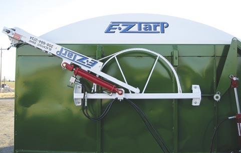
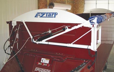
6 Mounting Framework 1. Make sure there is ten inches of space between the truck cab and box, eighteen inches down from the top of the box. 2. remove any protrusions, i.e.; weld beads, bolt heads, from the top of each side of the box. 3. attach the two channel irons to the front headboard using 3/8" x 1" bolts and lock washers. Before tightening the bolts make sure the channel irons are the same distance apart at each end. Center the headboard on the front of the box with the channel irons extending down the inside of the box. Using the channel irons as a template drill out the four 1/2" holes toward the bottom of the channels and the top 3/8" holes near the top. 4. (Illustration 1, see page 9) insert the 1/2" bolts through the lower holes from the inside of the box and place the spacer blocks over the bolts on the outside. some applications may require spacer blocks on the inside also. slide the front swing arm frame over the bolts followed by flat washers and nylocks. place 3/8" bolts through the top of the channel irons and tighten all of the nuts down. For a solid rear frame the mounting procedure is the same as the front frame. 5. (Illustration 8 [Spudnik] & 9 [Others], see page 13) Mount tarp stops along the passenger side of the box spacing them evenly. Three are used on 20 and 22 boxes and four are used on 24 and 26 boxes. 6. (Illustration 2, see page 9) Clamp the corner frame along the right side of the box with the longer angle iron covering the right rear corner. drill 3/8" holes, two in each of the frame angle irons, and bolt the frame to the box using spacer blocks if needed. 7. Mount the hinge frame by inserting 1" brass bushings into each end of the 1¼" pipe on the corner frame. Then holding the hinge frame in position, slide the hinge pin through the holes in the hinge frame and the brass bushings. lock the pin in place with a 3/8" bolt, nut, and lock washer. 8. (Illustration 3, see page 10) insert the 2" square tubing of the rear swing arm frame into the hinge frame. Center the pivot shaft of the swing arm in the middle of the box and tighten the set screws of the hinge frame. 9. slide the rear headboard support into the swing arm frame leaving the set screws loose. set the rear headboard in place and insert two 3/8" bolts through the headboard support and corresponding holes in the headboard. On the right side of the headboard insert a 7/16" bolt through the slot in the headboard and the top of the hinge frame with flat washers on top and bottom held in place with a 7/16" nylock. Center the headboard and tighten the bolts of the headboard support and the set screws of the swing arm frame. level the headboard along the top of the box using the angled adjusting rod of the hinge frame. Finally tighten the 7/16" nylock holding the headboard. 5
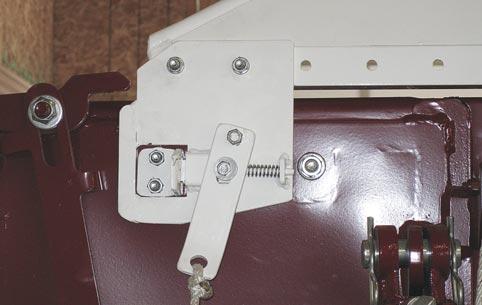
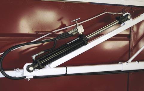
7 Mounting Framework, cont. 10. (Illustration 4, see page 10) Bolt the latch plate to the left side of the rear headboard adjusting the plate to miss any protrusions on the rear of the box. set the striker block in its latch plate opening and push the latch plate against the box. Mark and drill holes through the striker block into the rear of the box. Bolt the striker block to the box using flat washers to shim out the striker block if needed. Tie the latch rope to latch arm. For tarpers made after 2012 the striker block is mounted to the right side of the latch plate opening. Mounting the Hydraulic System 1. Mount the power unit in the correct place according to the brand of bulk box being used. Most mount near the left front corner. some, such as a spudnik box (Illustration 6, see page 11), mount farther back along the left side of the box. For semi-trailers refer to the semi parts page. 2. Thread the control cable into the truck cab through a convenient route making sure that the cable doesn t get pinched or is in an area where it will wear through or get burned. Mount the toggle switch in the cab, ideally in the dash and away from the side door and rear gate switches. after the toggle switch is in place connect the power in red wire to the power in lead of the side door pump. 3. (Illustration 5, see page 11) Mount the hydraulic cylinders to the swing arm frames with the tube end connected to the frame and the shaft end connected to the swing arm. Make sure that the bypass valves on the valve blocks are open (turn counter clockwise to open). 4. (Illustration 7, see page 12) route hoses #2 & #3 along the side of the box according to the application or box brand. The new logan and double l boxes will use hydraulic pipes along the passenger side of the box where the sides slope inward. attach hose #3 to the short loose hose on each valve block. attach hose #2 to the swivel fitting on the rear valve block and leave the other end hanging loose near the pump. attach hose #1 to the swivel fitting on the front valve block and port B (see hydraulic schematic) on the pump. after connecting the hydraulic hoses push the swing arms to the passenger side of the box. 6
8 Charging the Hydraulic System 1. Make sure hose #2 is disconnected from pump, the blue pump wire is disconnected from the solenoid and the a port of the pump is tightly plugged. 2. Fill the pump reservoir with automatic transmission fluid (dexron 3). always make sure that the oil level doesn t go below the minimum mark on the pump reservoir during the charging procedure. place hose #2 in an empty container. 3. run the pump until the oil reaches the minimum mark (this will be referred to as running the pump down). after the first run down hose #1 will be full and oil will begin filling the front cylinder. Close the bypass valve on the front valve block, fill the pump and run down twice. This will bring the front swing arm to the driver side. When this achieved open the front bypass valve. Fill and run down the pump two more times to get oil to the rear cylinder then close the rear bypass valve and with the same procedure as the front move the rear swing arm to the driver side. With both swing arms moved across the box and oil running from hose #2 remove the plug from port a and replace it with hose #2. Now the rear bypass valve can be opened up. With both bypass valves opened run the pump to make sure all air is purged from the system. 4. Connect the blue wire of the pump to the open solenoid stud and run the pump again in the opposite direction to make sure air is pushed out in this direction. When purging is finished close both bypass valves and move the swing arm to the passenger side of the box leaving the arms about one foot above the box corners. Mounting the tarp and roller 1. Bolt the front swing arm extension to the two bolt flange bearing on the front shaft of the roller. Make sure that the bearing, collar, and chain sprocket are loose on the shaft with the caution sticker facing away from the tarp and roller. remove the outer set collar from the rear roller shaft, insert two 1" brass bushings into the 1¼" pipe of the rear shaft pivot and slide the bushings and rear swing arm extension onto the roller shaft. Make sure that the shaft pivot is turned to the inside of the y of the swing arm extension and the set screws of the extension face away from the tarp and roller. slide the outer set collar onto the shaft and tighten it close to the end of the shaft. leave the inner set collar loose. 2. lift the complete tarp and roller assembly up on the passenger side of the truck box and slide the swing arm extension onto the swing arm. (On 100" wide boxes make sure to slide a 3" spacer onto the swing arm before the arm extension). 3. let the tarp unroll down the outside of the box and slide the anchor pipe through the pocket on the loose end of the tarp. Using the hydraulic system, move the roller to the driver s side of the box making sure that the tarp does not snag on any parts. 7
9 Mounting the tarp and roller, cont. 4. lift the tarp and anchor tube up to the top of the truck box and set it into the tarp stops. adjust the anchor pipe and tarp even with the ends of the truck box then close the tarp stops. 5. align the roller pipe so that the ends are the same distance from the ends of the box and tighten down the set collars on the rear shaft and the bearing collar and sprocket on the front shaft. The sprocket should be nearly touching the bearing collar. 6. slide the bungie anchors into each end of the tarp anchor pipe and raise the roller up about one third of the way up across the box. Feel for the bungie cord along the pockets on each end of the tarp and work the bungie cord through the tarp pocket to the passenger side of the box. Clamp the end of the bungie cord in the anchor with about 1½ inches sticking out. 7. Move the tarp roller back to the driver s side, about ten inches from the side of the box. slide the tensioning wheel onto the front shaft. Make sure it is close enough to the swing arm so that the stop tabs on the wheel can catch. Begin turning the wheel counter clockwise to tension the spring inside the roller. after 1½ turns lock the wheel in place and make sure the tarp ends and bungie straps are winding around the shaft and not around the roller tube. Continue turning the wheel another 2½ turns or until the slack is pulled out of the tarp ends and there is a small amount of sag in the center of the tarp. (Use caution when tensioning the spring, there is much torque and you may loose your grip on the wheel). 8. attach the roller drive chain around the roller sprocket and the corresponding arm sprocket. Tighten the chain using the adjusting bolt on the swing arm, and then tighten the arm extension set screws. Move the roller to the passenger side of the box and adjust the rear swing arm extension so that the ¾ inch bolt of the swing arm pivot is lined up with the hinge pin of the corner frame, then tighten the set screws of the swing arm extension. 9. roll the tarp back to the driver side to make sure there is contact down the length of the box. if the rear corner does not make contact with the top side of the box, open the front bypass valve on the hydraulic cylinder and run the toggle switch to close. The rear corner of the roller should close down tight against the box. Close the front bypass valve. Be sure to bolt the chain guard to the front swing arm. Walk around the truck checking the hydraulic system for leaks and use zip ties to secure any loose or sagging hoses. 8

10 Illustration 1 Illustration 2 9
11 Illustration 3 Illustration 4 10
12 Illustration 5 Illustration 6 11
13 Wiring Schematic Hydraulic Schematic Hydraulic Schematic with Pipe Illustration 7 12

14 Illustration 8 Illustration 9 13


15 Mounting parts for Semi trailers toggle Switch Box locate switch box six inches above the trailer fender with bolt holes centered on trailer corner post. drill hole 7/32 and tap out for 1/4 NC bolt. secure with 1/4 bolt and lock washer. pump Box The pump box mounts on the front passenger side angle iron post on the trailer. locate the box down far enough to allow the door to close. drill 3/8 holes in the center of angle iron and tub support. Mount box using 3/8 x 1 1/4 bolts, lock washers and nuts. (Arrows show location of bolts) double Header after mounting inner headboard and front swing arm frame attach outer headboard to the inner headboard using 3/8 x 2 ½ bolts flat washers and nylocks. 14
16 Front Frame ref # part # description Qty. P A R T S solid HEadBOard (1) CHaNNEl iron (2) spacer BlOCK (4) 4. * ½" BOlT (4) 5. * ½" NylOCK (4) 6. * ½" FlaT WasHEr (4) 7. a01 FrONT swing arm FraME (1) 8. a03 #50 X 63" CrOss OvEr CHaiN (1) 9. a04 ½" X 5" allthread (1) 10. a05 CHaiN TENsiONiNG spring (1) ¼" Brass BUsHiNG (2) ¼" MaCHiNE BUsHiNG (1) ¼" X 2" KOTTEr pin (1) 14. a02 FrONT swing arm (1) 15. a06 double sprocket (1) " Brass BUsHiNG (1) 17. a07 1" MaCHiNE BUsHiNG (1) 18. a08 3/16" X 1½" KOTTEr pin (1) 19. a idler sprocket (1) 20. a11 ⅝" NylOCK (1) ½" X 3" square HEad adj. BOlT (1) " EXTENsiON spacer (1) swing arm EXTENsiON (1) ½" X ¾" socket set screw (1) " X TWO BOlT FlaNGE BEariNG (1) 26. a12 1" ECCENTriC COllar (1) 27. * 7/16 " X 1½" BOlT (2) 28. * 7/16" NUT (2) 29. * 7/16" lock WasHEr (2) 30. a13 50 X 15 X 1" sprocket (1) 31. a14 ¼" X 1" KEy stock (1) 32. a15 #50 roller CHaiN (76" Or 82") (1) CHaiN GUard (1) 34. * ¼" X ¾" BOlT (2) 35. * ¼" lock WasHEr (2) 36. * ¼" FlaT WasHEr (2) HOsE ClaMp (1) 38. * ⅜" lock WasHEr (1) 39. * ⅜" NUT (1) TENsiONiNG WHEEl (1) * See bolt list 16
17 Front Frame Swing Arm Frame and Headboard 17
 7. C04 5/16\" X 1\" BOlT (1) 8. C05 5/16\" FlaT WasHEr (1) 9. * 3/8\" NylOCK (1) 10. C13 latch BOlT (1) 11. C14 latch HaNdlE 2013 (1) 12. C15 spring 2013 (1) 13.")
 3. G05 spring (l-2.00, W-0.80) (1) 4. G06 5/16\" FlaT WasHEr (1) 5. G07 5/16\" NylOCK (1) 6. G01 BOlT BraCKET (1) 7.")
18 Latch plate ref # part # description Qty. 1. C11 plate (1) 2. C02 latch BOlT (1) 3. C03 spring (l-1.75, W-.062) (1) 4. C08 latch HaNdlE shim (1) 5. C07 latch HaNdlE (1) 6. C06 latch HaNdlE BUsHiNG (1) 7. C04 5/16" X 1" BOlT (1) 8. C05 5/16" FlaT WasHEr (1) 9. * 3/8" NylOCK (1) 10. C13 latch BOlT (1) 11. C14 latch HaNdlE 2013 (1) 12. C15 spring 2013 (1) 13. C16 striker 2013 (1) 14. C17 sm latch plate 2013 (1) 15. C18 lg latch plate 2013 (1) * See bolt list Side Latch ref # part # description Qty. 1. G03 receiver BraCKET (1) 2. G04 latch HaNdlE (1) 3. G05 spring (l-2.00, W-0.80) (1) 4. G06 5/16" FlaT WasHEr (1) 5. G07 5/16" NylOCK (1) 6. G01 BOlT BraCKET (1) 7. G02 angle iron ClaMp (2) P A R T S P A R T S * See bolt list 2013 Latch plate Side Latch Latch plate 19
19 Swing Out rear Frame ref # part # description Qty. P A R T S rear latching HEadBOard (1) latch plate COMplETE (1) 3. C10 striker BlOCK (1) HEadBOard support (1) rear swing arm FraME (1) ½" X ¾" socket set screw (2) ¼" Brass BUsHiNG (2) ¼" MaCHiNE BUsHiNG (1) ¼" X 2" KOTTEr pin (1) 10. B03 rear swing arm (1) ½" X 3" square HEad adj. BOlT (1) " EXTENsiON spacer (Wide box) (1) rear swing arm EXTENsiON (1) 14. B04 pivoting KNUCKlE (1) 15. B05 ¾" X 6" BOlT (semi trl. 8½") (1) 16. B06 ¾" NylOCK (1) HiNGE FraME (1) ½" X 1" socket set screw (2) 19. * ¾" NUT (2) HiNGE pin (1) COrNEr FraME (1) spacer BlOCK (1¼"or 2") (2) " Brass BUsHiNG (2) 24. * ⅜" BOlT (various lengths) 25. * ⅜" NUT 26. * ⅜" lock WasHEr 27. * ⅜" FlaT WasHEr 28. * ⅜" NylOCK HOsE ClaMp 30. H23 side latch assembly * See bolt list 20
20 Swing Out Rear Frame Hinge Frame, Swing Arm Frame 21
21 Solid rear Frame ref # part # description Qty. P A R T S solid HEadBOard (1) CHaNNEl iron (2) spacer BlOCK (4) 4. * ½" BOlT (4) ½" NylOCK (4) 6. * ½" FlaT WasHEr (4) 7. B01 rear swing arm FraME (1) ¼" Brass BUsHiNG (2) ¼" MaCHiNE BUsHiNG (2) ¼" X 2" KOTTEr pin (1) 11. B03 rear swing arm (1) ½" X 3" square HEad adj. BOlT (1) " EXTENsiON spacer (Wide box) (1) swing arm EXTENsiON (1) ½" X ¾" socket set screw (1) " X TWO BOlT FlaNGE BEariNG (1) 17. a12 1" ECCENTriC COllar (1) 18. * 7/16" X 1½" BOlT (2) 19. * 7/16" NUT (2) 20. * 7/16" lock WasHEr (2) HOsE ClaMp (1) 22. * ⅜" lock WasHEr (1) 23. * ⅜" NUT (1) * See bolt list 24
22 Solid Rear Frame Swing Arm Frame and Headboard 25
23 tarp and roller assembly ref # part # description Qty. P A R T S 1. d02 roller TUBE (1) 2. d03 1" X 4' KEyEd shaft (1) 3. d08 TENsiONiNG spring (1) 4. d10 spring anchor CONE (1) 5. d09 spring TENsiON CONE (1) " set COllar (1) 7. d05 UHMW insert (4) 8. d11 ¼" X 2" BOlT (2) 9. d12 ¼" NylOCK (2) 10. d07 FrONT shaft sleeve (1) 11. d X 1" sprocket (1) 12. a14 ¼" KEy stock (1) 13. d04 1" X 4' anchor ENd shaft (1) 14. d13 #14 HEX HEad screw (2) " Brass BUsHiNG (2) 16. d01 Tarp-18 Mil vinyl (1) 17. d17 BUNGE strap (2) 18. d14 BUNGE ClaMp rod (2) 19. d18 BUNGE ClaMp plate (2) 20. d16 ¼" NUT (2) GalvaNiZEd anchor pipe (1) anchor ClaMp HOsE ClaMps (varies w/application) spacer BlOCK (varies w/application) 25. * ⅜" BOlT (various lengths) 26. * ⅜" lock WasHEr 27. * ⅜" FlaT WasHEr 28. * ⅜" NUT * See bolt list 28
24 Tarp and Roller Assembly 29
25 6 South 1000 West Blackfoot, ID
Patriot. Aluminum and Steel 5spring. Step #1 Tarp Spool with Gear Motor (Includes Instructions for Optional Wind Deflector)
") Aluminum and Steel 5spring Qty. Component Parts Description: LONG BOX: (1) 103 Aluminum Tarp Axle (2) 98 Upper Arms with 90 Degree Elbow (2) Lower Aluminum ( 84 ) (1) Aluminum Cross Tube SMALL HARDWARE
Aluminum and Steel 5spring Qty. Component Parts Description: LONG BOX: (1) 103 Aluminum Tarp Axle (2) 98 Upper Arms with 90 Degree Elbow (2) Lower Aluminum ( 84 ) (1) Aluminum Cross Tube SMALL HARDWARE
LIFT N LOAD INSTALLATION, MAINTENANCE, & SAFETY INSTRUCTIONS (800)
") LIFT N LOAD INSTALLATION, MAINTENANCE, & SAFETY INSTRUCTIONS (800) 272-6276 001-321-757-7611 www.cramarotarps.com Plants In: Delaware, Florida, Massachusetts, Nevada, Ohio, and Canada General Information
LIFT N LOAD INSTALLATION, MAINTENANCE, & SAFETY INSTRUCTIONS (800) 272-6276 001-321-757-7611 www.cramarotarps.com Plants In: Delaware, Florida, Massachusetts, Nevada, Ohio, and Canada General Information
SIDEWINDER 350 INSTALLATION INSTRUCTIONS & OPERATION MANUAL NOVEMBER 2011
 SIDEWINDER 350 INSTALLATION INSTRUCTIONS & OPERATION MANUAL NOVEMBER 2011 PATENT PENDING Donovan Enterprises 3353 SE Gran Park Way, Stuart FL 34997 800-327-8287 www.donovan-ent.com PACKING LIST FOR SIDEWINDER
N. 15th Street, Middlesboro, KY TARP-N-GO SYSTEMS INSTALLATION INSTRUCTIONS
 1-800-248-7717 1002 N. 15th Street, Middlesboro, KY 40965 TARP-N-GO SYSTEMS INSTALLATION INSTRUCTIONS Congratulations on your purchase of a Mountain Tarp Tarp-N-Go tarping system. With tarping systems
Combine Cover Manual
 Combine Cover Manual Installation Instructions Page 27 Operating Instructions Page 8 Warranty Page 8 Trouble Shooting Page 9 11 For Model s: Case I.H. 2388, 2188, 1688 and 1680 With a MAURER Hopper Extension
Smooth Roll Advantage Side Dump
 Smooth Roll Advantage Side Dump Installation, Maintenance and Safety Instructions Sioux City Tarp 5201 Harbor Drive Sioux City, IA 51111 Ph: 712-258-6939 Getting Started Important: Please read manual thoroughly
Combine Cover Manual
 Combine Cover Manual Installation Instructions Page 26 Operating Instructions Page 7 Warranty Page 7 Trouble Shooting Page 8 10 For Big Top Extension Model s: Case I.H. 8010, 8120 Please forward onto Customer
Side Kick 2. Installation Instructions & Parts Lists. Attention Dealers: Please give this owners manual to the customer when the product is delivered.
 Serving the Truck & Trailer Industry Since 1944 Side Kick 2 Installation Instructions & Parts Lists Attention Dealers: Please give this owners manual to the customer when the product is delivered. Call
PORTA-DOCK, INC. 65A 1155 DOUBLE PERSONAL WATERCRAFT LIFT
 Page 1 of 9 PORTA-DOCK, INC. 65A 1155 DOUBLE PERSONAL WATERCRAFT LIFT Thank you for purchasing our product! Please read these instructions and follow them step by step.* STEP 1. Separate and group like
INSTALLATION INSTRUCTIONS
 INSTALLATION INSTRUCTIONS Thank you for purchasing an AUTOLOCK Electric Tarp. ACI proudly manufactured this product using superior quality materials and workmanship. With proper care, your tarp will provide
Universal Super Shield & Ultimate Aluminum w/electric Drive Conversion Kits , , Installation Instructions
 WLH 09/19/16 111-0215 & 112-0215 607-0026 For technical support call us at (800) 368-3075 or visit our website at PullTarps.com. TABLE OF CONTENTS ***Assembly*** Conversion Kit-Universal Super Shield ***Wiring,
Side Kick 2 06/01/2013 Jan/06/14 Rev: Dec 8/2015 Rev: May 27/2016 Side Dump Trailer Tarp Cover
 Side Dump Trailer Tarp Cover Installation, Maintenance, Safety Instructions Attention Dealers: Please give this manual to the customer when the product is delivered. 1 Important: This manual explains how
Midwest Industries, Inc. Ida Grove, IA Page 1
 SSV40108HAC - Hydraulic Hoist with 120 Volt Pump SSV40108HDAC - Hydraulic Hoist, Deep Water, with 120 Volt Pump SSV40108HDC - Hydraulic Hoist with 12 Volt Pump SSV40108HDDC - Hydraulic Hoist, Deep Water,
Easy Cover. Installation Instructions. Attention Dealers: Please give this owners manual to the customer when the product is delivered.
 Serving the Truck & Trailer Industry Since 944 Easy Cover Attention Dealers: Please give this owners manual to the customer when the product is delivered. Call 00-3-94 www.aeroindustries.com Indianapolis,
Installation Instructions. Attention Dealers: Please give this owners manual to the customer when the product is delivered.
 Serving the Truck & Trailer Industry Since 1944 Attention Dealers: Please give this owners manual to the customer when the product is delivered. Call 800-535-9545 www.aeroindustries.com Indianapolis, IN
Lower Adjuster Small Black Header Sensor Reversed
 Parts List for Combine Quantity by Model Early Late Early Late Note: Indented items indicate parts included M M M M M M in an assembly listed above F F F F F F 7 7 8 8 8 8 5 6 5 5 6 6 Part Name/Description
Illustrated Parts & Packing List & Instructions 815 Rice Lake Street, Owatonna, MN 55060
 Illustrated Parts & Packing List & Instructions 815 Rice Lake Street, Owatonna, MN 55060 Great Plains Part #891-561C (Gandy Part #6245DS-GP) For Great Plains Turbo-Max 2400, 3000, 3500 & 4000 Models 45
BELLY DUMP MANUAL AND ELECTRIC INSTALLATION INSTRUCTIONS AND OWNER S MANUAL
 BELLY DUMP MANUAL AND ELECTRIC INSTALLATION INSTRUCTIONS AND OWNER S MANUAL BY: INSTALLER: These instructions must be given to the consumer. CONSUMER: Retain these instructions for further use. Save this
CALIFORNIA TRIMMER MOWER MAINTENANCE MANUAL
 CALIFORNIA TRIMMER MOWER MAINTENANCE MANUAL 2 Table of Contents Section 1: General Information Page Handle Assembly Instructions 4 Maintenance All Models 6 Oil Change Procedures All Models 9 Height Adjustment
INSTALLATION, MAINTENANCE, & SAFETY INSTRUCTIONS
 Tarpaulin Systems Flip -N- Go / Quick Mount Flip -N- Go System INSTALLATION, MAINTENANCE, & SAFETY INSTRUCTIONS (800) CRAMARO (800) 272-6276 Plants In: Delaware, Florida, Massachusetts, Nevada, Ohio Install
It don t mean a thing If it ain t got the swing
 SWING CHUTE SAND/SALT SPREADER INSTALLATION AND OPERATING INSTRUCTIONS SWING CHUTE SPREADER MODELS: 7, 8, 9, 9.5 & 10 MANUAL FOR SPREADER SERIAL NUMBERS AFTER # 20000 It don t mean a thing If it ain t
INSTRUCTIONS, (FORD) SUPER DUTY INSTALLATION KIT (C2 PICKUP LIFTGATES)
 SUPER DUTY INSTALLATION KIT (C2 PICKUP LIFTGATES)") LIFT CORPORATION Sht. 1 of 22 DSG# M-16-32 Rev. - Date: 12/13/16 INSTRUCTIONS, (FORD) SUPER DUTY INSTALLATION KIT (C2 PICKUP LIFTGATES) FORD SUPER DUTY F-250, F-350 & F-450 PICKUP TRUCKS, 2017 MODEL KIT
LIFT CORPORATION Sht. 1 of 22 DSG# M-16-32 Rev. - Date: 12/13/16 INSTRUCTIONS, (FORD) SUPER DUTY INSTALLATION KIT (C2 PICKUP LIFTGATES) FORD SUPER DUTY F-250, F-350 & F-450 PICKUP TRUCKS, 2017 MODEL KIT
ENCORE 52" X-TREME. 2-BAG GRASS CATCHER for units w/ S/N and above ASSEMBLY AND PARTS DIAGRAMS
 ENCORE 52" X-TREME 2-BAG GRASS CATCHER for units w/ S/N 53138 and above ASSEMBLY AND PARTS DIAGRAMS Notes: ASSEMBLY INSTRUCTION Figure 1 Using 1/2" wrench, remove the discharge cover and the RH deck belt
42A FLB WOOD BUNKS 43A FLB ALUMINUM BUNKS ALUMINUM CANTILEVER BOAT LIFT
 Page 1 of 9 42A --- 1265 FLB WOOD BUNKS 43A --- 1265 FLB ALUMINUM BUNKS ALUMINUM CANTILEVER BOAT LIFT Thank you for purchasing our product! Please read these instructions and follow them step by step.*
Installation Instructions February 2009
 Installation Instructions February 2009 www.donovan-ent.com Donovan Enterprises 3353 SE Gran Park Way Stuart, FL 34997 800-327-8287 The Hammer Head Assembly Installation Instructions (Rollerbar & Direct
AIRCRAFT LANDING GEAR CONSTRUCTION MANUAL
 APPENDIX AI KITPLANES FOR AFRICA AIRCRAFT LANDING GEAR CONSTRUCTION MANUAL Revision: C September 2008 Page L1 of 20 NOTE: Please read the General Manual before proceeding. Please read through the entire
SRT-2 MANUAL AND ELECTRIC
 Installation Manual SRT-2 MANUAL AND ELECTRIC BY: INSTALLER: These instructions must be given to the consumer. CONSUMER: Retain these instructions for further use. Save this manual for future reference.
Installation Guide CLAAS Lexion Combines with 9 inch Elevators
 Installation Guide CLAAS Lexion Combines with 9 inch Elevators 955614_01 4/17 1 Table of Contents System Overview 3 Quick Start Guide 4 Flow Sensor Installation 5 Hydraulic Elevator Adjustment Kit Installation
Parts Manual Rev. B RZT48 /
 115 91 36-2 Rev. B Parts Manual RZT48 / 96 62001-00 Please read the operator manual carefully and make sure you understand the instructions before using the machine. Gasoline containing a maximum of 10%
Easy Cover. Parts Lists Attention Dealers: Please give this owners manual to the customer when the product is delivered.
 Serving the Truck & Trailer Industry Since 1 Easy Cover s Attention Dealers: Please give this owners manual to the customer when the product is delivered. Call 00-- www.aeroindustries.com Indianapolis,
PARTS MANUAL THIS PAGE INTENTIONALLY LEFT BLANK. Ag-Bag International, Ltd. G7000 June Appendix A
 The parts manual is organized into groups, it is designed to make the locating of parts easier. The exploded drawings also show assembly paths. All parts listed are available from your authorized Ag-Bag
INSTALLATION MANUAL. Thunderstone Manufacturing LLC 3400 West O Street Lincoln, NE (Fax)
") INSTALLATION MANUAL August 7 th 2018 43 /48 /50 2011 and Older Timpte STD/Split 36 Style Hopper Trailers with Roller Bearing Doors Kit #101533 for 96w & Kit #101534 for 102w Thunderstone Manufacturing
INSTALLATION MANUAL August 7 th 2018 43 /48 /50 2011 and Older Timpte STD/Split 36 Style Hopper Trailers with Roller Bearing Doors Kit #101533 for 96w & Kit #101534 for 102w Thunderstone Manufacturing
Illustrated Parts & Packing List & Instructions 815 Rice Lake Street, Owatonna, MN 55060
 Illustrated Parts & Packing List & Instructions 815 Rice Lake Street, Owatonna, MN 55060 Great Plains Part #891-622C (Gandy Part #6245DS-TT) Great Plains Turbo-Till & Turbo-Chopper 2400/3000 Models 45
GRAIN CART TARP SYSTEM INSTALLATION AND OPERATION MANUAL
 GRAIN CART TARP SYSTEM INSTALLATION AND OPERATION MANUAL Grain Carts KITS Thunderstone Manufacturing, LLC. 3400 West O Street Lincoln, NE 68528 402-435-4249 (Fax) 402-438-3918 www.thunderstonemfg.com Aluminum
Agri-Fab OWNER'S MANUAL. Model No POINT HITCH TRAILER.
 Agri-Fab OWNER'S MANUAL Model No. 45-0353 3-POINT HITCH TRAILER CAUTION: Read Rules for Safe Operation and Instructions Carefully Safety Assembly Operation Maintenance Parts the fastest way to purchase
Illustrated Parts and Packing List & Instructions 815 Rice Lake Street, Owatonna, MN 55060
 Illustrated Parts and Packing List & Instructions 815 Rice Lake Street, Owatonna, MN 55060 Page 1 of 30 Phone: 800-443-2476 / 507-451-5430 www.gandy.net / Email: sales@gandy.net 6231DS16F Orbit-Air Applicator
N. 15th Street, Middlesboro, KY CRUSHED CAR HAULER INSTALLATION INSTRUCTIONS
 1-800-248-7717 1002 N. 15th Street, Middlesboro, KY 40965 CRUSHED CAR HAULER INSTALLATION INSTRUCTIONS Congratulations on your purchase of a Mountain Tarp Crushed Car Hauler tarping system. With tarping
Wildcat System Instructions
 Wildcat System Instructions NOTE: Most steps contained in these instructions will need to be repeated on the other side of the vehicle. Prior to assembly of windshield it is necessary to establish what
Siderolling Tarp Systems Under 9 6 Wide
 Load Loc Select Maximizer Grain Carts Grain Bagger Siderolling Tarp Systems Under 9 6 Wide CRANK STYLE INSTALLATION INSTRUCTIONS MICHEL S INDUSTRIES, LTD. P.O. BOX 119 ST. GREGOR, SK. S0K 3X0 PH:306.366.2184
INSTALLATION & OWNER S MANUAL
 Pg. 1 of 14 INSTALLATION & OWNER S MANUAL John Deere Gator XUV 825i S4 Cab (p/n: 1GTRXUV4 Steel Cab with Doors) The contents of this envelope are the property of the owner. Be sure to leave with the owner
INSTRUCTIONS, NISSAN TITAN TRUCK INSTALLATION KIT (C2 PICKUP LIFTGATES)
") LIFT CORPORATION Sht. 1 of 18 DSG# M-14-33 Rev. A Date: 05/31/2017 INSTRUCTIONS, NISSAN TITAN TRUCK INSTALLATION KIT (C2 PICKUP LIFTGATES) NISSAN TITAN PICKUP TRUCKS, 2004-2015 KIT P/N 295040-01 MOUNTING
LIFT CORPORATION Sht. 1 of 18 DSG# M-14-33 Rev. A Date: 05/31/2017 INSTRUCTIONS, NISSAN TITAN TRUCK INSTALLATION KIT (C2 PICKUP LIFTGATES) NISSAN TITAN PICKUP TRUCKS, 2004-2015 KIT P/N 295040-01 MOUNTING
Section B Detector September B
 Section B Detector September 200 B Index No. Part No. Description. 2-0030-000 Link 2. 2-0208-000 Deck Hook Selector Assembly 3. 2-003-000 Spacer. -3000-000 Ball Bearing. 2-00-02 X-Washer Pin. 2-008-02
250P Manure Spreader
 0P Manure Spreader Illustrated Parts Breakdown Page - Page Page Page Page Page Page Page Page Page Page Page Page Page Page - Page Page Page 0 Complete Front End PTO/Jack/Hitch Assembly Front Pulley Assembly
Ford Torino Small Block Rack Kit Instructions
 1968-69 Ford Torino Small Block Rack Kit Instructions 8012290-01 Unisteer offers a limited warranty against all manufacturer defects of their kits and supplied parts. Unisteer will not honor any warranty
INSTRUCTIONS, (FORD) SUPER DUTY INSTALLATION KIT (C2 PICKUP LIFTGATES)
 SUPER DUTY INSTALLATION KIT (C2 PICKUP LIFTGATES)") LIFT CORPORATION Sht. 1 of 20 DSG# M-14-32 Rev. B Date: 05/31/2017 INSTRUCTIONS, (FORD) SUPER DUTY INSTALLATION KIT (C2 PICKUP LIFTGATES) FORD SUPER DUTY F-250 PICKUP TRUCKS, 1999-2016 FORD SUPER DUTY
LIFT CORPORATION Sht. 1 of 20 DSG# M-14-32 Rev. B Date: 05/31/2017 INSTRUCTIONS, (FORD) SUPER DUTY INSTALLATION KIT (C2 PICKUP LIFTGATES) FORD SUPER DUTY F-250 PICKUP TRUCKS, 1999-2016 FORD SUPER DUTY
ProPass-200 Top Dresser
 Setup Manual Form No. 3365-184 Rev A ProPass-200 Top Dresser Model No. 44700-Serial No. 310000001 and Up Model No. 44701-Serial No. 310000001 and Up Model No. 44704 Model No. 44705 Model No. 44706 Model
Ag Leader Technology. Parts List for Combine MF , 8780, White 9700
 Parts List for Combine Quantity by Model Note: Indented items indicate parts included W in an assembly listed above 8 8 8 8 H 5 5 5 7 I 6 7 9 8 T Part Name/Description Part No. 0 0 0 0 E Instruction Kit
INSTALLATION & OWNER S MANUAL
 Rev. E p. of 3 INSTALLATION & OWNER S MANUAL V446 Front Cab Kit and V446 Rear Cab Kit for RTV 40 INSTALLATION & OWNER S MANUAL The contents of this envelope are the property of the owner. Be sure to leave
Grass Catcher. Instructional / Parts Manual Part Number: January ( & ) & Drive Kits ( , , )
 & Drive Kits ( , , )") Grass Catcher Instructional / Parts Manual Part Number: January 200 5020 ( 507 & 5026 ) & Drive Kits ( 52030, 5203, 52032) Table of Contents Z RIDER GRASS CATCHER TWO PACKAGED ITEMS LIST 507 BLOWER ASSEMBLY
Grass Catcher Instructional / Parts Manual Part Number: January 200 5020 ( 507 & 5026 ) & Drive Kits ( 52030, 5203, 52032) Table of Contents Z RIDER GRASS CATCHER TWO PACKAGED ITEMS LIST 507 BLOWER ASSEMBLY
AmTryke Adult Recumbent Model HP1000 #50-HC-1000
 AmTryke Adult Recumbent Model HP1000 #50-HC-1000 TOOLS Needed for Assembly 5 mm Allen Wrench 8 mm Socket or Wrench 10 mm Socket or Wrench 14 mm Socket or Wrench 15 mm Socket or Wrench 22 mm Socket or Adjustable
Additional Instructions for 6" Drop
 Serving the Truck & Trailer Industry Since 1944 Additional Instructions for 6" Drop Attention Dealers: Please give this manual to the customer when product is delivered. Call 800-535-9545 www.aeroindustries.com
Parts Manual Rev. A RZT54 /
 115 93 37-27 Rev. A Parts Manual RZT54 / 967 672101-00 Please read the operator manual carefully and make sure you understand the instructions before using the machine. Gasoline containing a maximum of
Retriever 5100G/P. 11/89 revised 10/02 FORM NO
 Retriever 5100G/P PARTS LIST Advance MODELS 56497000, 56497010 This parts list is for machines after serial number 353005 All models covered in this manual are OBSOLETE 11/89 revised 10/02 FORM NO. 56042216
MAINTENANCE INSTRUCTIONS
 MAINTENANCE INSTRUCTIONS LSR90 SERIES RAMPS Link Mfg. Ltd. 223 15th St. N.E. Sioux Center, IA USA 51250-2120 The LSR 90 fits Mercedes Benz Sprinters, Ford Transits mid and high roof, Nissan NV high roof,
Parts Manual EZF 3417/ Please read the operator s manual carefully and make sure you understand the instructions before using the machine.
 Parts Manual EZF 3417/ 96579301 Please read the operator s manual carefully and make sure you understand the instructions before using the machine. English 200 HTC. All Rights Reserved. Beatrice, NE. Printed
Installation Guide. Installation Guide. Exploded Views Installation Instructions Mounting System Parts List. USTarp.
 Installation Guide Installation Guide Exploded Views Installation Instructions Mounting System Parts List USTarp.com 800-249-0297 Fits dump trailers up to 40 long, or up to 45 long with Bulletproof HD
Owner s Manual. LPR4500RB Hide-A-Way LPR45RBSR Hide-A-Way Trailer Rear Gate
 Owner s Manual LPR4500RB Hide-A-Way LPR45RBSR Hide-A-Way Trailer Rear Gate LEYMAN MANUFACTURING CORPORATION 10900 Kenwood Road Cincinnati, OH 45242 1-866-LEYMAN-1 1-866-539-6261 513-891-6210 Fax 513-891-4901
Spare Parts B WR
 7 CRT 52 1.1997 Spare Parts 954 14 00-20B WR 01-07-98 HANDLE ASSEMBLY 1 871191008 Screw, Phd. #10-24 UNC 2 532126956 Panel, Control 3 532104164 Tie, Cable 4 532124797 Grip, Handle 5 532124788 Clip, Hairpin
SAFETY SAFETY CABLE INSTALLATION /00 1 of 6
 SAFETY DO NOT INSTALL, OPERATE OR USE THIS EQUIPMENT UNTIL THE FOLLOWING OPERATING AND SAFETY INSTRUCTIONS HAVE BEEN READ AND UNDERSTOOD. This symbol is used to bring attention to safety precautions and
EZ-LOC HAND AND ELECTRIC INSTALLATION INSTRUCTIONS AND OWNER S MANUAL
 EZ-LOC HAND AND ELECTRIC INSTALLATION INSTRUCTIONS AND OWNER S MANUAL TYPICAL OF FARM TRUCK, GRAIN CART, AND SEMI-TRAILER BOXES INSTALLER: These instructions must be given to the consumer. CONSUMER: Retain
GROB 4V-24 Parts. GrobBandSaw.com
 GROB 4V- Parts GrobBandSaw.com 888-550-3116 18 19 20 21 22 5/16-18x1/2 Hex Head Cap Screw ( 14 ) 34 35 36 37 38 39 40 39 41 42 43 44 45 46 17 16 3/8-16x3/4 Hex Head Cap Screw ( 2 ) 31 30 15 5/16-18x1 Hex
Hi Cap 54 Grain Cleaner
 OWNER S MANUAL Hi Cap 54 Grain Cleaner PNEG-1147 Date: 3-1-02 PNEG-1147 SAFETY INFORMATION PLEASE READ WATCH FOR THIS SYMBOL! IT POINTS OUT IMPORTANT SAFETY PRECAUTIONS. IT MEANS, ATTENTION - BECOME ALERT!
Model 802 Center Mount Adapter For New Holland 9030 & TV140 Bi-Directional Tractors PARTS CATALOG
 Model 802 Center Mount Adapter For New Holland 9030 & TV140 Bi-Directional Tractors 1 PARTS CATALOG TABLE OF CONTENTS Frame & Tractor Linkage...2,3 Header Linkage & Float Group...4,5 Header Drive Hydraulics
Installation Manual. LHS & LLBS Hide-A-Way Tuckunder Style
 Installation Manual LHS & LLBS Hide-A-Way Tuckunder Style 10900 Kenwood Road Cincinnati, OH 45242 Ph: 513-891-6210 Toll-Free: 866-539-6261 Fax: 513-891-4901 www.leymanlift.com sales@leymanlift.com LML00136-5/1/15
PORTA-DOCK, INC. 100A 1284 ALUMINUM CANTILEVER BOAT LIFT
 Page 1 of 7 PORTA-DOCK, INC. 100A 1284 ALUMINUM CANTILEVER BOAT LIFT Thank you for purchasing our product! Please read these instructions and follow them step by step. * STEP 1. Separate and group like
LAWN TRACTORS ELECTRIC CLUTCH HYDRO DRIVE SERIES "G"
 Parts Manual for LAWN TRACTORS ELECTRIC CLUTCH HYDRO DRIVE SERIES "G" MODEL LT160H42GBV LT160H42GBV2 LT180H48GBV2 WLT160H42GBV WLT180H48GBV2 McDonough, GA, 30253 U.S.A. COPYRIGHT 2006 SNAPPER PRODUCTS,
AIR INTAKE EMERGENCY SHUT-OFF VALVE C50207 AIR INTAKE SHUT-OFF VALVES APPLICATION FORD 6.7L POWERSTROKE.
 AIR INTAKE EMERGENCY SHUT-OFF VALVE C50207 AIR INTAKE SHUT-OFF VALVES APPLICATION 2011-2016 FORD 6.7L POWERSTROKE www.powerhalt.com Thank you for your purchase of a PowerHalt Air Intake Emergency Shut-Off
Stapler Folder Model 82 Spare Parts List
 Stapler Folder Model 82 Spare Parts List Oct 2004 Part No. 76344 Contents TITLE PAGE REVISION Outer view, Infeed 1.1 Oct -04 Outer view, Outfeed 1.3 Jan -03 Front view (cover removed) 1.5 Jan -03 Rear
PORTA-DOCK, INC. 100A 1200 LB. 84 WIDE ALUMINUM CANTILEVER BOAT LIFT 102A 1200 LB. 113 WIDE ALUMINUM CANTILEVER BOAT LIFT
 Page 1 of 7 PORTA-DOCK, INC. 100A 1200 LB. 84 WIDE ALUMINUM CANTILEVER BOAT LIFT 102A 1200 LB. 113 WIDE ALUMINUM CANTILEVER BOAT LIFT Thank you for purchasing our product! Please read these instructions
Parts Manual Rev. A RZT48 /
 115 91 36-2 Rev. A Parts Manual RZT48 / 96 62001-00 Please read the operator manual carefully and make sure you understand the instructions before using the machine. Gasoline containing a maximum of 10%
Reproduction. Not for. Mid Frame Dual Stage Snowthrowers. Parts Manual
 Parts Manual Attachment Mfg. No. Description 1695821 (I1224E), 11.5TP 24" Dual Stage Snowthrower 1695842 (I924EX), 9TP 24" Snowthrower (CE/Export) Mid Frame Dual Stage Snowthrowers Not for Reproduction
Operations Manual Eagle 1000 Series Stretch Wrapper
 Operations Manual Eagle 1000 Series Stretch Wrapper Models A & B - 1 - READ ALL INSTRUCTIONS CONTAINED IN THIS MANUAL PRIOR TO MACHINE INSTALLATION! - 2 - Contents page 1. Machine Safety Information 1.1
AmTryke Adult Recumbent Model JT2000 #50-FC-2000
 AmTryke Adult Recumbent Model JT2000 #50-FC-2000 TOOLS Needed for Assembly 5 mm Allen Wrench 8 mm Socket or Wrench 10 mm Socket or Wrench 14 mm Socket or Wrench 15 mm Socket or Wrench 22 mm Socket or Adjustable
PFadvantage JD 3300/4400/6600/7700; 4420
 Ag Leader Technology Combine Installation JD 33//66/77; 2 Note: Indented items indicate parts included Quantity by Model in an assembly listed above Early Late Part Name/Description Part Number 3 3 6 6
A B C D E F. Tools Required (supplied by others)
") Page 1 of 17 Parts List Below Deck Automatic Retractable Security Cover Kit (1) Tube End Bearing Plate (A) (1) Rope Reel and Cover Drum Motor Assembly (B) (1) Cover Drum (1) Pulley Support Channel (2)
Page 1 of 17 Parts List Below Deck Automatic Retractable Security Cover Kit (1) Tube End Bearing Plate (A) (1) Rope Reel and Cover Drum Motor Assembly (B) (1) Cover Drum (1) Pulley Support Channel (2)
Reproduction. Not for. Mid Frame Dual Stage Snowthrower. Parts Manual
 Parts Manual Attachment Mfg. No. Description 1695994 (I924EX), 9TP 24" Snowthrower (CE/Export) Mid Frame Dual Stage Snowthrower Not for Reproduction Manual Part No. Revision - Rev. Date: 7/20/2011 Table
K B J K A C H D E I F. Single and Bi-Parting Electric Sliding Doors with Automatic Operator (ICC-5) Parts List. R-PLUS Cold Storage Doors
 Parts List. R-PLUS Cold Storage Doors") Single and Bi-Parting Electric Sliding Doors with Automatic Operator (ICC-) Parts List K B J K A C H G Release Date: -0 D E R-PLUS Cold Storage Doors NE 9th Portland, Oregon 90 Toll Free () 0-99 Fax (0)
Single and Bi-Parting Electric Sliding Doors with Automatic Operator (ICC-) Parts List K B J K A C H G Release Date: -0 D E R-PLUS Cold Storage Doors NE 9th Portland, Oregon 90 Toll Free () 0-99 Fax (0)
MOUNT BRACKET PARTS and HARDWARE: Installation parts with * come loose in hardware kit bag. Other parts are preassembled
 INSTALL INSTRUCTIONS C-DMM-2006 Dash Monitor Mount 2017-2019 F-250, 350, 450 Pickup, F-450 and 550 Cab Chassis, 2015-2019 Ford F-150 and 2018-2019 Expedition Notes: 1. The C-DMM-2000 series Dash Monitor
Universal Platform. 222 Model Section 3. Platform Parts Breakdown (1997 Present) Retractable Finger Auger Parts Breakdown...
 Retractable Finger Auger Parts Breakdown...") Universal Platform 222 Model Section 3 Platform Parts Breakdown (1997 Present)... 2-4 Retractable Finger Auger Parts Breakdown... 5-6 Combine Pickup Head Parts Breakdown (1997 Present)... 7-10 4 Tube Pickup
Universal Platform 222 Model Section 3 Platform Parts Breakdown (1997 Present)... 2-4 Retractable Finger Auger Parts Breakdown... 5-6 Combine Pickup Head Parts Breakdown (1997 Present)... 7-10 4 Tube Pickup
INSTALLATION & OWNER S MANUAL
 Rev. B, p. 1 of 25 INSTALLATION & OWNER S MANUAL POLARIS RANGER RCS (for models XP or HD) (for model years 2009-) cab without doors kit (p/n 1POLRCWD) cab with doors kit (p/n 1POLRC) doors only kit (p/n
H.I.T. 5000H2 TRUCK TIRE CHANGER. Parts Identification
 TRUCK TIRE CHANGER Parts Identification READ these instructions before placing unit in service KEEP these and other materials delivered with the unit in a binder near the machine for ease of reference
SATURN SKY 2006 AND UP
 SATURN SKY 2006 AND UP THIS KIT INCLUDES: 16 M8-1.25X30MM BOLTS WITH WASHERS 2 SHOULDER BOLTS WITH RIGHT AND LEFT HINGE ASSEMBLY 2 SHOCKS 550 PSI WASHERS 2 PINS TOOLS REQUIRED FOR INSTALLATION: AIR RACHET,
PARTS LIST CHARGER 2717 DB
 PARTS LIST CHARGER 2717 DB ITEM PART NO. PART DESCRIPTION QTY. 101 6497261 AXLE / PIVOT MOUNT 2 102 9122260 3/8-16 X 1 HEX BOLT - PACK OF 2 4 103 9122100 3/8 SPLIT LOCK WASHER - PACK OF 10 4 104 9122180
Combine Pickup Heads
 Combine Pickup Heads 164 Model Section 3 Model Years 1991 1996... 2-5 Pickup Head Layout 1994 1996... 6-7 Model Years 1997 1999 (1 PUH Bearings)... 8-10 4 Tube Pickup Head Layout 1997 1999... 11-12 Model
MK-5000G exploded VieW
 Frame accessories 38 cutting head Pump Assembly 39 connecting linkage foot pedal linkage 40 curtain blade guard 41 ENGINE Assembly 42 PARTS LIST A Frames - - A1 Frame, MK-5000 Main 1 155541 B Pivot Bracket
TAILGATE SPREADER INSTALLATION INSTRUCTIONS
 SPREADER (Includes Models SA-6C, SA-9 & TGC-18) EFFECTIVE 12/2015 Revision B 1330 76TH AVE SW CEDAR RAPIDS, IA 52404-7052 PHONE (319) 363-8281 FAX (319) 286-3350 www.highwayequipment.com Copyright 2009
SEC PARTS MANUAL SERIAL NUMBERS: BODY: MAST: GRABBER: MFG. DATE: Made in the U.S.A.
 SEC PARTS MANUAL SERIAL NUMBERS: BODY: MAST: GRABBER: MFG. DATE: Made in the U.S.A. TABLE OF CONTENTS WARRANTY WARRANTY REGISTRATION FORM TABLE OF CONTENTS PAGE I PAGE II PAGE III PARTS SECTION 1 HYDRAULICS
Retriever 5800G/P/D. revised 2/01 Form Number
 Retriever 5800G/P/D PARTS LIST Advance MODELS 56482005, 56482010, 56482015 This parts list is for machines after serial number 221134 All models covered in this manual are OBSOLETE revised 2/01 Form Number
Installation Instructions Supertop NX Twill
 Installation Instructions Supertop NX Twill Vehicle Application: Jeep Wrangler Unlimited 2007-current Part Number 54823 Installation Tips Before you begin installing your new Supertop NX Twill, please
MODELS 470, 570, 670, 770 Corner Auger GRAIN CART (For Model 970 Information, Refer to Manual #250541)
") OPERATOR S MANUAL PARTS CATALOG MODELS 470, 570, 670, 770 Corner Auger GRAIN CART (For Model 970 Information, Refer to Manual #250541) PART NO. 250611 200026 Late Model 70 Series 290374 Early Model 70
OPERATOR S MANUAL PARTS CATALOG MODELS 470, 570, 670, 770 Corner Auger GRAIN CART (For Model 970 Information, Refer to Manual #250541) PART NO. 250611 200026 Late Model 70 Series 290374 Early Model 70
Agri-Fab OWNERS MANUAL. Model No " ROUGH CUT TRAILMOWER. CAUTION: Read Rules for Safe Operation and Instructions Carefully
 Agri-Fab OWNERS MANUAL Model No. 45-03071 45-0361 CAUTION: Read Rules for Safe Operation and Instructions Carefully Safety Assembly Operation Maintenance Parts 42" ROUGH CUT TRAILMOWER the fastest way
Drive End Bracket & Bearing. Drive End Bracket. Tandem Axle # #865733
 Drive End Bracket & Bearing #865089 1 06409700 1" Lock Collar 2 865733 Drive Bracket w/ Bearing 3 310037 End Drive Shaft Drive End Bracket #865733 1 03003100 Bearing 1" w/snap Ring 2 957795 Drive End Bracket
Lexion 570R/575R, 580R/585R, 590R/595R
 Note: Indented items indicate parts included in an assembly listed above Quantity by Model 2006+ All Years Part Name/Description Part Number 570R 575R 580R 585R Instruction Kit Lexion 570/580/590 2005500-5
MENTOR INSTALLATION, MAINTENANCE, & SAFETY INSTRUCTIONS (800)
") MENTOR INSTALLATION, MAINTENANCE, & SAFETY INSTRUCTIONS (800) 272-6276 001-321-757-7611 www.cramarotarps.com Plants In: Delaware, Florida, Massachusetts, Nevada, Ohio, and Canada Important: Read before
MENTOR INSTALLATION, MAINTENANCE, & SAFETY INSTRUCTIONS (800) 272-6276 001-321-757-7611 www.cramarotarps.com Plants In: Delaware, Florida, Massachusetts, Nevada, Ohio, and Canada Important: Read before
Combine Pickup Heads
 Combine Pickup Heads 124 Model Section 1 Model Years 1991 1996... 2-5 Pickup Head Layout 1994 1996... 6-7 Model Years 1997 1999 (1 PUH Bearings)... 8-10 4 Tube Pickup Head Layout 1997 1999... 11-12 Model
LAWN TRACTORS MANUAL CLUTCH HYDRO DRIVE SERIES "G"
 Parts Manual for LAWN TRACTORS MANUAL CLUTCH HYDRO DRIVE SERIES "G" MODEL ELT145H33GBV LT145H33GBV LT145H38GBV LT150H38GKV WLT145H38GKV McDonough, GA, 30253 U.S.A. COPYRIGHT 2006 SNAPPER PRODUCTS, INC.
One Step Ahead Rod Cutter (Front Mount Unit)
") One Step Ahead Rod Cutter (Front Mount Unit) Pickup Head Gear System (LH End View) Section 6 Model Years 1992 1998... 2-3 Model Years 1998 1999 (1 PUH Bearing)... 4-6 Model Years 1998 2012 (1 1/4 PUH Bearing)...
One Step Ahead Rod Cutter (Front Mount Unit) Pickup Head Gear System (LH End View) Section 6 Model Years 1992 1998... 2-3 Model Years 1998 1999 (1 PUH Bearing)... 4-6 Model Years 1998 2012 (1 1/4 PUH Bearing)...
INSTALLATION GUIDE TCP RCKM-01
 READ ALL INSTRUCTIONS COMPLETELY AND THOROUGHLY UNDERSTAND THEM BEFORE DOING ANYTHING. CALL TOTAL CONTROL PRODUCTS TECH SUPPORT (916) 388-0288 IF YOU NEED ASSISTANCE. INSTALLATION GUIDE TCP RCKM-01 Manual
JEEVES. JEEVES Installation Manual. Installation Manual The Easiest Do-It-Yourself Dumbwaiter on the Market
 1 888-323-8755 www.nwlifts.com JEEVES Installation Manual The Easiest Do-It-Yourself Dumbwaiter on the Market This manual will cover the installation procedure step-by-step. The installation of this dumbwaiter
Website: ELIMINATOR MD. (701) (800)
 (800)") Website: www.tbei.com E-mail: sales@tbei.com ELIMINATOR MD www.rugbymfg.com sales@rugbymfg.com (701) 776-5722 (800) 533-0494 1228633 1 DATE PURCHASED BODY SERIAL NUMBER HOIST SERIAL NUMBER CYLINDER SERIAL
Website: www.tbei.com E-mail: sales@tbei.com ELIMINATOR MD www.rugbymfg.com sales@rugbymfg.com (701) 776-5722 (800) 533-0494 1228633 1 DATE PURCHASED BODY SERIAL NUMBER HOIST SERIAL NUMBER CYLINDER SERIAL