Assembly Manual FELIX One
|
|
|
- Anastasia Charles
- 5 years ago
- Views:
Transcription
1 Assembly Manual FELIX One Version Zeemanlaan MV IJsselstein The Netherlands
2 Introduction Table of Content Dear Customer, Thank you for choosing FELIXprinters! To get your Felix printer up and running as fast and painlessly as possible please follow this manual carefully. Please don t take any shortcuts. It s better to spend a few minutes extra on reading, than to wait a week for new parts. When things are unclear or if you have any remarks or tips, please contact us at support@felixprinters.com. We also recommend looking on our forum and getting yourself a forum account. You will benefit from the ability to get downloadable and printable upgrades for your printer. Also it is a great source to obtain and share knowledge about your 3D printer and 3D printing in general. Have fun building! Kind regards, FELIXprinters. Required tools 5 Chapter 1: Frame 6 Chapter 2: Z-axis 8 Chapter 3: X-axis 11 Chapter 4: Y-axis 15 Chapter 5: Print Head 19 Chapter 6: Wiring 27 Chapter 7: Upload Firmware 31 Chapter 8: Installing LCD 32 Chapter 9: Functional test 33 Chapter 10: Finishing Touch 35 Chapter 11: Checklist 36 Bill of Material 38 FELIXprinters Assembly Manual for the FELIX One Page 3

3 Notice Before starting the assembling: Check the content of the kit if it is complete according to the bill of material in the appendix of this document. FELIXprinters Assembly Manual for the FELIX One Page 4
4 Required 1,5 2 2, ,5 7,0 12 Hexagon Key 1,5mm Hexagon Key 2mm Hexagon Key 2,5mm Hexagon Key 3mm Hexagon Key 4mm Hexagon Key 5mm Tweezer Wrench 5,5 mm 7,0 mm and 12 mm + - Grease Lubricant Phillips Head Screwdriver Slotted Head Screwdriver Small Pliers Knife / Box Cutter Rubber Hammer* Tape Measure Alcohol *Or use a steel hammer with a soft piece of rubber or plastic to absord the impact. FELIXprinters Assembly Manual for the FELIX One Page 5

 Profile 4 (2x) Bolt M8 x 20")

 Profile 2 (1x) Bolt M8 x 20")
5 Chapter 1: Frame 30 Minutes 1!! Hole!! 2!! Hole!!!! Hole!! 5 (1x) Profile 4 (2x) Bolt M8 x 20 (2x) Frame Connector 5 (1x) Profile !! Hole!!!! Hole!!!! Hole!! 160mm!! Hole!! 160mm!! Hole!! 5 (1x) Profile 2 (1x) Bolt M8 x 20 (1x) Frame Connector 5 5 FELIXprinters Assembly Manual for the FELIX One Page 6
 Profile 2 (1x)")
")
 Frame")


 End Cap Rectangle")
6 6 7 8!! Hole!! (1x) Profile 2 (1x) Bolt M8 x 20 (1x) Frame Connector 5 5 (1x) Profile 3 (2x) Bolt M8 x 20 (2x) Frame Connector Make sure the profiles are properly aligned. If not untighten the screws and readjust the profiles. (4x) End Cap Square (1x) End Cap Rectangle FELIXprinters Assembly Manual for the FELIX One Page 7


 CSK Bolt M3 x 8 (1x)")
 Motor Assembly (2x)")

7 Chapter 2: Z-Axis 45 Minutes i , Example - Insert T-Nut: Insert the nut into the slot 2 Example - Insert T-Nut: Insert the key into the threaded hole and rotate the nut into position (4x) CSK Bolt M3 x 8 (1x) Motor (1x) Z-Axis Motor Bracket 2 (1x) Cable Stepper Z (1x) Motor Assembly (2x) T-Nut M4 (2x) Bolt M4 x 20 (2x) Small Washer M4 3 FELIXprinters Assembly Manual for the FELIX One Page 8

 Z-Axis Lift (1x)")


 Bearing (2x) Bolt M4 x 25 (2x) Small")
8 cm 16cm 28cm!! Don t let the Carriage run of the Rail!! (3x) T-Nut M4 (3x) Bolt M4 x 20 (1x) Linear Guide HGW15 (1x) Z-Axis Lift (1x) Hexagon Nut 2 Use tape measure to allign. 3 18!! Remove Bolts after pulling Locknuts into Z-Axis Lift!! 19 20!! Washer!!!! Washer!! (2x) Bolt M4 x 40 (2x) Locknut M4 3 (4x) Bearing (2x) Bolt M4 x 25 (2x) Small Washer M4 3 FELIXprinters Assembly Manual for the FELIX One Page 9

 Z-Axis Lift Assembly (4x) Bolt M5 x 16 (4x) Small Washer")
 Cable Stepper Y 24 25 26!")


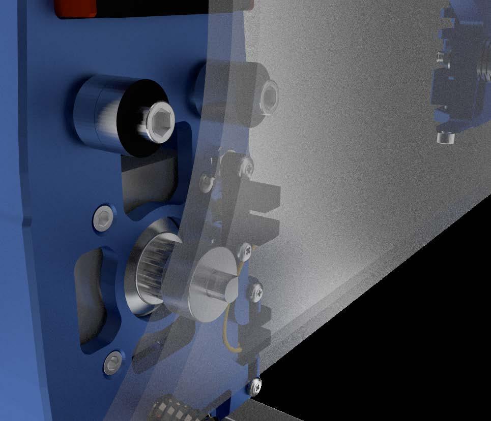
9 21!! Tighten in a Crosswise Pattern!! 22 23!! Make sure the flat side of the Motor Axle is Perpendicular to the Set Screw!! (1x) Z-Axis Lift Assembly (4x) Bolt M5 x 16 (4x) Small Washer M5 4 (1x) Motor (1x) Pulley (1x) Set Screw M3 x 6 (1x) Cable Stepper Y 1,5 (1x) Cable Stepper Y !! Make sure the Hexagon Nut stays in its Socket!!!! Apply Grease to the Spindle. Do NOT use Oil as Lubricant!!!! Make sure the flat side of the Motor Axle is Perpendicular to the Set Screw!! (1x) Motor Assembly (4x) CSK Bolt M3 x 8 2 (1x) Spindle (1x) Set Screw M3 x 6 Note: use a high quality and sharp 1.5 mm allen key to properly fix the spindle on the motor. 1,5 FELIXprinters Assembly Manual for the FELIX One Page 10

 Bearing (1x) Small Washer")


 Belt (1x) X-Axis Belt")
10 Chapter 3: X-Axis 60 Minutes 27 28!! Washer!! 1,5 2 2, ,5 14 (1x) T-Nut M4 2 (2x) Bearing (1x) Small Washer M4 (1x) X-Axis Belt Mount (1x) Bolt M4 x !! Make sure the short side of the T-nut is facing the corner of the frame!! (1x) Belt (1x) X-Axis Belt Mount Assembly (1x) T-Nut M4 3 2 FELIXprinters Assembly Manual for the FELIX One Page 11
 T-Nut M4")
 X-Axis Motor")


 T-Nut M3 (black) (1x)")
 Linear Guide MGN12 2")
11 (1x) Bolt M4 x 16 (1x) Small Washer M4 3 (1x) T-Nut M4 (1x) Bolt M4 x 16 (1x) Small Washer M4 (1x) X-Axis Motor Bracket mm from the side of the rail to side of the frame!! 14 mm!! Reposition the Safety Plugs as shown!! (2x) T-Nut M3 (black) (1x) Linear Guide MGN12 (2x) Bolt M3 x 12 (1x) Linear Guide MGN12 2 2,5 FELIXprinters Assembly Manual for the FELIX One Page 12


 Cable Stepper X 41 42 43!")

 Opto Sensor X (4x) CSK")
12 38!! Make sure to Position the Rail against X-Axis Belt Mount!! 39 40!! Make sure the flat side of the Motor Axle is Perpendicular to the Set Screw!! 2,5 (1x) Motor (1x) Pulley (1x) Set Screw M3 x 6 1,5 (1x) Cable Stepper X !! Tighten in a Crosswise Pattern!! !! Use Tweezer to Position the Bolts!! (1x) Motor Assembly (4x) CSK Bolt M3 x 8 (2x) Small Screw 2,2 x 8 (1x) Opto Sensor X (4x) CSK M3 x 6 (1x) Extru Base FELIXprinters Assembly Manual for the FELIX One Page 13


 Tension Bracket (1x) Square Nut")
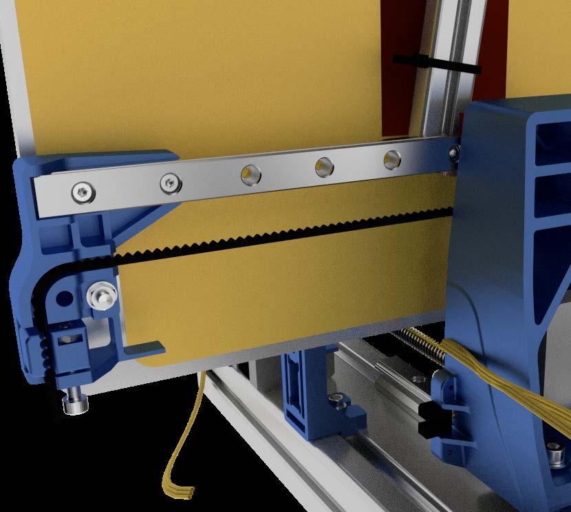
13 44 45!! Use a screwdriver to Push the Belt completely into the Socket!! !! Insert the Square Nut into the Tension Bracket!! !! Use the Screwdriver to Push the Belt completely into the Socket!!!! Move the carriage to the center of the rail. Tighten the belt using the size 3 hexagon key until the belts can barely touch eachother when pressing them together!! 2 cm (1x) Tension Bracket (1x) Square Nut M4 (1x) Tension Bracket Assembly (1x) Bolt M4 x 25 3 FELIXprinters Assembly Manual for the FELIX One Page 14
 Thin Nut M4!")
 Small Screw 2,2 x 8 (2x) Thin Nut M4 (1x) Opto sensor")
 Y-Stage Bracket Pt.1 (1x) Y-Stage Bracket Pt.")

 Bolt M4 x 25 (1x) Square Nut M4 3 (4x)")
14 Chapter 4: Y-Axis 30 Minutes 50 51!! Don t let the Carriage run of the Rail!!!! (1x) Thin Nut M4!!!! Endswitch Vane!! + - 2,5 3 5,5!! (1x) Thin Nut M4!! 52 (2x) Small Screw 2,2 x 8 (2x) Thin Nut M4 (1x) Opto sensor Y (4x) Bolt M3 x 16 (4x) Locknut M3 (4x) Small Washer M3 (1x) Y-Stage Bracket Pt.1 (1x) Y-Stage Bracket Pt.2 (1x) Hiwin Linear Guide MGN12 2,5 5,5!! Tighten in a Crosswise Pattern!! (2x) Bolt M3 x 12 (1x) Y-Stage Bracket 2,5 (1x) Tension Bracket (1x) Bolt M4 x 25 (1x) Square Nut M4 3 (4x) Bolt M3 x 16 (4x) Small Washer M3 (1x) Y-Stage Assembly 2,5 FELIXprinters Assembly Manual for the FELIX One Page 15


 Belt -")
15 55!! Use the Screwdriver to Push the Belt completely into the Socket!! 56 57!! Use the Screwdriver to Push the Belt completely into the Socket!! M3 x cm Tensioning the Belt: Move the Y-Axis completely to one end. Tighten the belt using the size 3 hexagon key until the belt can barely touch the rail of the Y-Axis (1x) Belt (1x) Build Platform (1x) Short Wire Sleeve FELIXprinters Assembly Manual for the FELIX One Page 16

 Thumb screw (2x) Spring (1x) Build Platform")


 Bolt M4 x 16 (1x) Spring")
16 !! Repeat for Front and Rear Thumbscrew!!!! Give the Cable enough Slack and tighten the Cable Ties!! (2x) Thumb screw (2x) Spring (1x) Build Platform Assembly (2x) Cable Tie 64!! Tighten the Bolt against the end of the Thread!! 65 66!! Give the Cable enough Slack and tighten the Cable Tie!! End to End 25cm (1x) Bolt M4 x 16 (1x) Spring (1x) Cable ties for mounting cables on z bracket (1x) Cable ties for mounting cables on z bracket 3 FELIXprinters Assembly Manual for the FELIX One Page 17
 Large Washer M4 (1x) Bolt M4 x 12 (1x) Thin Nut M4 (1x) Spring 3 (1x) Extru Arm Pt.")
 Extru Arm Pt.")
17 Chapter 5: Print Head 90 Minutes 69 70!! For Dual Head: Repeat this Step!!!! For Dual Head: Repeat this Step!! 1,5 1,5 2,5 3 (2x) Large Washer M4 (1x) Bolt M4 x 12 (1x) Thin Nut M4 (1x) Spring 3 (1x) Extru Arm Pt. 1 (1x) Bearing 71!! For Dual Head: Repeat this Step!! 72 73!! For Dual Head: Repeat this Step!!!! Repeat this Step!!!! Make sure the flat side of the Motor Axle is Perpendicular to the Set Screw!! (1x) Extru Arm Pt. 2 (1x) Motor (1x) Extruder drive wheel (1x) Set Screw M3 x 6 1,5 (1x) L-Bracket (1x) Square Nut M4 FELIXprinters Assembly Manual for the FELIX One Page 18
 Bolt M4 x")

 Motor 2,5 (1x) Square Nut")
 L-Bracket")
18 74!! Repeat this Step!! Motor E1 Motor E1 (1x) Bolt M4 x 40 Bolt is used to keep square nut in place during assembly. 3 (3x) Bolt M3 x 16 (1x) L-Bracket Assembly (1x) Motor 2,5 (1x) Square Nut M4 (1x) Extruder Arm Assembly (1x) Spring Assembly 77 Motor E1 (1x) L-Bracket FELIXprinters Assembly Manual for the FELIX One Page 19


 Place")

19 ! Make sure the sticker from the fan is at the back. The fan blows on the side of the sticker Align the print head on the carrier 98 Label end of the hot-endcable: 0 Mount the bolt loosely. Label end of the wire: ,5 100! Tighten the bolt (2x M4) Place nuts for ease of assembly. 2,5 FELIXprinters Assembly Manual for the FELIX One Page 20


20 (2x) Bolt M4 x 40 (used in step 74) Connect sensor assembly and the fan + LED onto the main assembly. 2, (2x M4) Place nuts for ease of assembly. 2,5 FELIXprinters Assembly Manual for the FELIX One Page 21
 small cable tie bundle cables, but do not tighten too much.")


21 x 2 x Guide fan wires to front of bracket. (3x) small cable tie bundle cables, but do not tighten too much. (2x) print head assembly Bend wires a little bit so they come to the front, while heads are still parallel to each other Remove nuts (placed in step 98) 2. (1x) small cable tie Mount front assembly. Bundle print head wires, motor wire and sensor wire. Place cable tie loosely. (2x) normal cable tie (1x) Long cable sleeve Mount left motor wire and print head wires together with cable bundle from right side. (2x) M4 x 12 Connect extruder assembly by placing two bolts. 2,5 2,5 FELIXprinters Assembly Manual for the FELIX One Page 22

22 Place flexplate on top of buildplate. 2. Move z-sensor above leveler wheel. 3. Move platform up, until left or right hot-end touches build plate. 4. Adjust height of z-sensor, until the distance between sensor and leveler wheel is the thickness of the calibration card. (Detailed Z-height calibration process is explained in the Quick Start Guide) FELIXprinters Assembly Manual for the FELIX One Page 23
 Single Cable Clip (1x) Angled Cable Clip 110 111 112")

23 Chapter 6: Wiring Minutes 24cm End to End 38cm + 3 (2x) Single Cable Clip (1x) Angled Cable Clip (1x) Single Cable Clip (2x) Single Cable Clip (2x) Dual Cable Clip FELIXprinters Assembly Manual for the FELIX One Page 24


")

24 x Y-stage bracket pt1 1x Y-stage bracket pt2 4x Bolt M3x16 4x Smal washer M3 4x Self locking nut M x Bolt M3x8 1x Small t-slot M3 1x Y stage tensioning bracket 1x Thin nut M4 1x Bolt M4x25 (1x) Electronic Enclosure Assembly 3 FELIXprinters Assembly Manual for the FELIX One Page 25


25 ! ATTENTION: Bottom of set-screw should NOT touch plate internally. Keep distance of approx. 0.5mm 3x Set screw M4x30 3x Thin nut M Large washer! Tighten the nuts a couple of turns, make sure that the springs are still able to compress for further fine-adjustment later. 3x spring 2x Small washer 1x Large washer 3x Thin nut M4 2x tie-wrap FELIXprinters Assembly Manual for the FELIX One Page 26


26 x 25 cm Cable spiral /- 1cm Belt! Mount the belt, according to the arrows. FELIXprinters Assembly Manual for the FELIX One Page 27


27 ! Ends of the plastic strip must be cut at an angle! 1x 25 cm Cable spiral 1x Clamp + Cable tie 1x 13 cm Plastic U-profile 116 The y-axis and the print bed are finished. FELIXprinters Assembly Manual for the FELIX One Page 28
 Power Supply (1x) Electronic")
 Power Supply Screw (1x) Electronic 1 +")


 Bolt M4 x 12 (1x) Electronic")
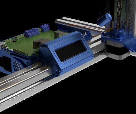
28 End to End 25 cm (2x) Power Supply Screw (1x) Power Supply (1x) Electronic Enclosure Pt. 2 + (2x) Power Supply Screw (1x) Electronic Enclosure Pt !! Position the narrow edge upwards!! 117!! Make sure to position the left T-Nut against the profile!! cm!! First slide the Enclosure against the left T-Nut, next slide the right T-Nut with Bolt into the Slot. Finally tighten the Two Bolts!! (1x) Electronic Enclosure Cover Plate (2x) T-Nut M4 (2x) Bolt M4 x 12 (1x) Electronic Enclosure Assembly 3 3 FELIXprinters Assembly Manual for the FELIX One Page 29

29 Overview: Control Board Note: E0 = E1 on control board Important: Set the Blue Potentiometers to the correct value as shown in the overview Tighten the screw terminals with force to ensure a good connection Make sure the Control board is positioned correctly, so that the underside doesn t touch the power supply. Main board side Red Blue Green Black Black Red Green Blue Motor side FELIXprinters Assembly Manual for the FELIX One Page 30

 Square Nut M4 (1x) Control")
 end Y = Endswitch Y (Opto")
 Display Assembly")
30 !! Plug the connector into the matching socket description!! (4x) Square Nut M4 (1x) Control Board end X = Endswitch X (Opto sensor) end Y = Endswitch Y (Opto sensor) Z sensor cable has no label. 125 (1x) Display Assembly FELIXprinters Assembly Manual for the FELIX One Page 31
31 Chapter 7: Upload Firmware 15 Minutes Download the Firmware: Download the latest FELIX One Firmware version from: Upload the Firmware to the Control Board: 1. Unzip the downloaded file to a convenient location. (Note: if you click on the zip file from within the Windows explorer, it will NOT be unzipped. You just view the content of the zip. You need to select the files and drag them to the desired location.) 2. Connect your printer to your computer and turn it on. Do not make a connection at this time with the printer with programs like Repetier-Host or Simplify3D. 3. Start the batch file upload_automatic.bat. A script will start in a command window. 4. The script will try to detect what COM port your printer is using. Check if this is correct, and then proceed by entering Y in the command window. 5. The firmware is uploaded when Programming finished! is displayed, this may take a few minutes. 6. Press any key to continue. The FELIX One firmware is now successfully uploaded. Note for Experienced Users: Due to compatibility issues with linux based systems, the baudrate for the FELIX Tec 4 is lowered to Make sure to adjust the settings in the used software accordingly. FELIXprinters Assembly Manual for the FELIX One Page 32


")


32 x Small screw 2,2 x (1x) Display Interface PCB (1x) Display Assembly 1x Plastic Display-cover FELIXprinters Assembly Manual for the FELIX One Page 33


33 ! Connecting the display cables (2x)!! Clean the surface of the frame first before applying the damping feet!! Align the square nuts from step 88 properly before mounting the cover with the m4x12 bolts. (2x) (2x) (6x) Damping Feet FELIXprinters Assembly Manual for the FELIX One Page 34

34 Chapter 9: Functional Test 10 Minutes In order to make sure all motors, sensors and LCD panel are connected properly, the following tests need to be performed Main board Tec 4 Check heaters: Check Sensor Connections: Z-sensor The z-sensor can be tested by holding a metal object underneath the sensor. Check if the z-sensor LED turns off. When the z-sensor indication LED on the main board switches off, the sensor is activated. Y-sensor Manually move the bed to its end position to activate the y-sensor. Check if the y-sensor LED turns off. When the y-sensor indication LED on the main board switches off, the sensor is activated. X-sensor Manually move the extruder to its end position to activate the x-sensor. Check if the x-sensor LED turns off. When the x-sensor indication LED on the main board switches off, the sensor is activated. IMPORTANT: Keep hand near ON/OFF switch of printer, in case things go wrong. Warm up left extruder (E1). Note: The hot-ends might smell a bit the first time heating. This is because of a small amount of oil within certain parts. Click rotary button to enter the main menu --> Control --> scroll down to heater --> Click on E1 and rotate until setpoint temperature increases to about 100 degc. Then check if temperature for that heater goes up. Repeat these steps for the right extruder (E2) and for the Bed (55degC). FELIXprinters Assembly Manual for the FELIX One Page 35
35 Check Motor Cable Connections: IMPORTANT: Keep hand near ON/OFF switch of printer, in case things go wrong. X-axis motor To make sure the wires are connected as required it is important to test all connections. To do so for the x-axis: enter menu by pushing the rottary button --> Control --> Move --> Home X Y-axis motor To test the y-axis: enter menu by pushing the rottary button --> Control --> Move --> Home Y Z-axis motor NOTE: When doing home z, extruders heatup to 120 DegC to prevent possible filament blobs from scratching the kapton surface layer. Important: ensure flexplate is placed on the print bed. To test the z-axis: enter menu by pushing the rottary button --> Control --> Move --> Home Z FELIXprinters Assembly Manual for the FELIX One Page 36


 Kapton Foil 132 133 134!")
36 Chapter 10: Finishing Touch 15 Minutes 131!! Peel off the protective sheet at the corner and stick the exposed adhesive to the BuildPlate at one corner!! Preheat your buildplate to 60 C degrees to make sure the Kapton Foil will have good adhesion to the flexible plate. 2!! Continue peeling off the protective sheet and at the same time stick the foil to the BuildPlate using a soft object in a zigzag motion to avoid air bubbles!! (1x) Kapton Foil !! Use the Screwdriver to center the Square Nut before inserting the Bolts!! (4x) M4 x 12 (1x) Electronic Enclosure Cover + 3 (1x) Main Fan Cover Connect the fan cover onto the extruder unit. FELIXprinters Assembly Manual for the FELIX One Page 37
37 Chapter 11: Checklist Frame: 1. Frame bolts (6x) are properly fixed. 2. Frame profiles are perpendicular and propely aligned. 3. Damping feet are placed underneath the printer. X-axis: 1. X-axis rail is properly aligned. 2. Bolts (2x) X-axis rail are properly fixed. 3. X-axis belt pushed fully into bracket and tensioner. 4. Belt remains at same height during moving the X-axis. 5. Set screw (1x) for pulley is fixed at the correct height with set screw. 6. X-axis belt tensioned properly Y-axis: 1. Bolts for stacked bearings (4x) guiding the belt are properly fixed. 2. Y-axis carriage is properly aligned in the Z-axis lift. 3. Bolts (4x) of the Y-axis carriage are properly fixed. 4. Y-axis belt pushed fully into bracket and tensioner. 5. Belt remains at same height during moving the Y-axis. 6. Set screw (1x) for pulley is fixed at the correct height with set screw. 7. Y-axis belt tensioned properly. Z-axis: 1. Z-axis rail is properly aligned. 2. Bolts (3x) Z-axis rail are properly fixed. 3. Set screw (1x) Z-axis spindle is properly fixed. 4. Bolts (4x) connecting Z-axis carriage to the lift are propely fixed. 5. Z-axis spindle nut is properly fitted in the Z-axis lift. 6. Z-axis spindle is greased over its entire length. Build Platform: 1. Bolt (1x) center of build platform is properly fixed. 2. Build surface doesn t contain air bubbles. Print Head: 1. Extruder drive wheels properly aligned. 2. Bolts (2x) connecting print head to X-axis carriage are properly fixed. 3. Bolts (2x) sensor bracket are properly fixed. Electrical: 1. Wire harness properly fixed without rubbing against parts. 2. Wire harness loop for X, Y, Z-axis are at the correct length and do not get pulled under full extension. 3. Cables are not under tension and have enough slack. 4. Cable ties neatly cut off. 5. Connectors properly connected in sockets. 6. Potentiometers on control board are set to the correct values. 7. Control board contains the correct Tec 4 firmware version. 8. Wire colors are according to diagram. Online Test: 1. Build platform heats up to 90 degrees C, move cable harness to check for wire breakage. 2. Extruders heat up to 90 degrees C, move cable harness to check for wire breakage. 3. Hot-ends don t move during loading/unloading filament. 4. Check if filament gets pulled through firmly. FELIXprinters Assembly Manual for the FELIX One Page 38
38 Congratulations! You have finished building the FELIX One. Continue to the Quick Start Guide to start printing! FELIXprinters Assembly Manual for the FELIX One Page 39
39 Bill of Material Bolts and nuts set Part Quantity # Set screw D M3 x 6-N - 5 # Bolt D M3 x N - CSK 5 # Bolt D M3 x N - CSK 15 # Hexagon socket head cap screw DIN M3 x 12 5 # Hexagon socket head cap screw DIN M3 x # Hexagon socket head cap screw DIN 912 M4 x # Hexagon socket head cap screw DIN 912 M4 x 16 2 # Hexagon socket head cap screw DIN 912 M4 x 20 7 # Hexagon socket head cap screw DIN 912 M4 x 25 4 # Hexagon socket head cap screw DIN 912 M4 x 40 2 # Hexagon socket head cap screw DIN 912 M5 x 16 5 # WasherD-125A M3 6 FELIXprinters Assembly Manual for the FELIX One Page 40

40 # WasherD-125A M4 10 # WasherD-125A M5 5 # Corrosserie ring - M4 - large washer 2 # Prevailing torque type hexagon nut DIN M3 6 # Prevailing torque type hexagon nut DIN M4 6 # Hexagon Thin Nut D-439B - M4 8 # Powersupply screw UNC 6/32 x 1/4 Pozi steel 6 # Set screw D M4 x 30 2 # Spring Extruder & bed 4 # Thin square nut DIN Steel - M4 9 # t_slot nut - 8 ST M3 3 # Parker 2.2 x 8 - plaatschroef 6 FELIXprinters Assembly Manual for the FELIX One Page 41


41 Prod. Nr. Desciption Total Image Electronics bag Opto sensor X (Straight), cable and connectortec Opto sensor Y (Angled) cable + connector Tec Z-sensor calibration unit Double fan with cable and connector Tec4 1 FELIXprinters Assembly Manual for the FELIX One Page 42


42 cable ties, tie wrap - 100mm x 2.5 mm Cable ties for mounting cables on Z bracket Cable sleeve, nylon semi open set 95/ 115 cm Stepper Extruder0 cable Tec Stepper X-axis cable Tec4 1 FELIXprinters Assembly Manual for the FELIX One Page 43


43 Stepper Y-axis cable Tec Stepper Z-axis cable Tec4 1 Prod. Nr. Desciption Total Image Mechanic bag felix Tec Pulley motor - FELIX 3 and Pro series Tooth Belt bearing 624, 4x13x6 (packaged per 10) Extruder drive wheel FELIX 3/Tec4 1 FELIXprinters Assembly Manual for the FELIX One Page 44

44 platform support Felix Tec4 (Y-Bracket F3.5) Knurled thumb knob tec Z-adjustment right hot-end Fan finger guard 40x40 mm tec Dual Extruder Front Bracket - Tec Spacer rail and extruder wheel adjustment for Felix3.X 1 FELIXprinters Assembly Manual for the FELIX One Page 45
45 Prod. Nr. Desciption Total Image Parts packet separately in DIY kit Powersupply - FELIX Spindle - trapezium - Felix Assy build platform Felix Tec Hiwin linear ball bearing - MGN12H1R0300Z1HM Hiwin linear ball bearing - HGW15CC1R300Z0 1 FELIXprinters Assembly Manual for the FELIX One Page 46
46 Prod. Nr. Desciption Image Set plastic parts X_stage_F3_0_belt_mount_v1 - black Y stage bracket prt1 with inserts Felix Tec4 Black Y stage bracket prt2 with inserts Felix Tec4 Black Y_stage_F3_0_tensioning_bracket_v1 - black z_axis_f3_0_lift_part_v1 - black z_axis_f3_0_motor_bracket_v1 - black 1 FELIXprinters Assembly Manual for the FELIX One Page 47
47 Extru_F3_1_base - black Extru_F3_1_L_shape_bracket - black Extru_F3_0_arm_pt1_v1 - black Extru_F3_0_arm_pt2_v1 - black Electronics_enclosure_F3_0_cap_pt1 - black Electronics_enclosure_F3_0_cap_pt2 - black 1 FELIXprinters Assembly Manual for the FELIX One Page 48


48 Electronics_enclosure_F3_0_cover_plate_v1 - black Electronics_enclosure Felix Tec4 Black Sticker on control box, TEC Fan Cap airduct Tec4 - Black Fan front cover Tec4 - black Printed parts LCD cabinet Felix Tec4 - Black X_stage_F3_0_motor_bracket_v1 - black 1 FELIXprinters Assembly Manual for the FELIX One Page 49
49 Prod. Nr. Desciption Total Image FULL metal hotend FELIX Tec nozzle_felixprinters (0,35 mm pro1) Hotend base Felix Tec Heat break Felix Tec Felix 3 & Tec 4 - Heater Cartridge incl. connector Hot End Heated Barrel 1.75 Pro FELIX 3.1 & Tec4 - Thermistor incl. connector Teflon tube Hot-end (36,5 mm) Felix Tec Set screw D M3 x 4 3 FELIXprinters Assembly Manual for the FELIX One Page 50


50 Prod. Nr. Desciption Total Image Frame bag Felix3/ Tec frame connector set handle PA 160 for Felix Protective cap, handle PA160, FELIX T-slot nuts 8 ST M t_slot nut - 8 ST M x40 protective caps x40 protective caps damping foot (felix 3) bolkop inbus bolt M8x16 ITEM 2 FELIXprinters Assembly Manual for the FELIX One Page 51
51 Prod. Nr. Desciption Total Image Frame profile set Felix3/ Tec profiel 8 40x40x400 E PT1 1 profiel 8 40x40x400 E PT3 2 profiel 8 40x40x400 E PT4 1 profiel 8 80x40x440 E 1 FELIXprinters Assembly Manual for the FELIX One Page 52

 2 170 023.")

 1 122 044.")
52 Prod. Nr. Desciption Total Image Miscellaneous Felix 3.1/ Tec USB cable 1.8m Tweezers Teflon Tube for Pro and 3 series - (55cm) Filament dust cleaner PLA sample - 50 gram - Random Colours Filament guide/ dust cleaner holder Felix3/ Tec (printed) Filament bracket Felix3/ Tec (printed) - black 2 FELIXprinters Assembly Manual for the FELIX One Page 53


53 Prod. Nr. Desciption Total Image Optional parts depending on region Power cable EU Power cable US Power cable AU Power cable UK 1 FELIXprinters Assembly Manual for the FELIX One Page 54


54 Optional: depending on order Prod. Nr. Desciption Total Image Upgrade Single Tec to Dual Felix Tec Stepper motor Nema 17, 40 mm Stepper Extruder1 cable Tec Extruder drive wheel FELIX 3/Tec Hexagon socket head cap screw DIN M3 x Full metal hotend FELIX Tec Spring Extruder & bed Corrosserie ring - M4 - large washer Hexagon socket head cap screw DIN 912 M4 x 12 1 FELIXprinters Assembly Manual for the FELIX One Page Page 55 51
 1 170 023.1 Filament dust cleaner 1 105 128.")
55 Optional: depending on order Hexagon Thin Nut D-439B - M bearing 624, 4x13x6 (packaged per 10) Teflon Tube for Pro and 3 series - (55cm) Filament dust cleaner set Tie wraps 20 pieces in bag 1 FELIXprinters Assembly Manual for the FELIX One Page 56
Assembly Manual FELIX Tec 4
 Assembly Manual FELIX Tec 4 Version 5.2 2018 www.felixprinters.com support@felixprinters.com Zeemanlaan 15 401 MV IJsselstein The Netherlands Introduction Table of Content Dear Customer, Thank you for
Prusa i3 Printer Assembly Guide
 Prusa i3 Printer Assembly Guide Special thanks to Carlos Sanchez and Miguel Sanchez for the graphics. All graphics captured from their great animation: http://www.carlos-sanchez.com/ Prusa3/ For copyright
Modix Big-60 Assembly Instructions Part 1
 Modix Big-60 Assembly Instructions Part 1 Version 1.0, October 2017 Menu 1. X Idler Pulley Assembly... 3 2. Connecting X Axis Brackets to Z Profiles... 4 3. Assemble X Rails on X Top Profiles... 6 4. Assemble
5. Extruder Assembly
 5. Extruder Assembly Guide for the assembly of the Extruder. Written By: Josef Prusa 2018 manual.prusa3d.com/ Page 1 of 24 Step 1 Get the necessary tools 2.5 and 1.5 mm Allen key Needle-nose pliers 2018
Instruction manual. Felix 1.5b, 3d printer-kit. Version2-20-Jan Page 1 of 66
 Instruction manual Felix 1.5b, 3d printer-kit Version2-20-Jan-2013 Copyright Information This document contains proprietary information that is protected by copyright. No part of this document may be photocopied,
Modix Big-60 Assembly Manual Part 2
 Modix Big-60 Assembly Manual Part 2 Version 1.0, October 2017 Menu 1. Motors & End Stop Wiring... 3 2. Controller Wiring Check... 6 3. Extruder Wiring... 7 4. Electronic Box Cover... 9 5. Filament Sensor...
5. E-axis assembly. 5. E-axis assembly. Written By: Jakub Dolezal manual.prusa3d.com/ Page 1 of 40
 5. E-axis assembly Written By: Jakub Dolezal 2018 manual.prusa3d.com/ Page 1 of 40 Step 1 Tools necessary for this chapter Needle-nose pliers for zip tie trimming. 2.5mm Allen key for M3 screws 2mm Allen
How to replace a hot-end nozzle. 11 June FELIX Pro 1. Revision 2
 Revision 2 Introduction 1 1 Introduction This tutorial explains how to exchange a hot-end nozzle properly. A replacement can be needed, when the tip is completely clogged or when it is required to use
TL4076 Top 5 Tips Get to know your TL4076
 TL4076 Top 5 Tips Get to know your TL4076 Thermal Break with Teflon liner (behind fan) Hot End Assembly Fan Heat Block Extruder with toothed gear(brass) and idler (steel) Filament Guide Tube Nozzle Cable
Documentation version 1.42 ASSEMBLY INSTRUCTIONS REV 1.1
 Documentation version 1.42 ASSEMBLY INSTRUCTIONS REV 1.1 / 2 INTRODUCTION / 3 INTRODUCTION Target : Prupose a visual guide of the differents steps to build and use a µdelta printer Designers : Hugo Flye
8. Electronics assembly (B3/R2 design)
") 8. Electronics assembly (B3/R2 design) Written By: Jakub Dolezal 2018 manual.prusa3d.com/ Page 1 of 31 Step 1 Tools necessary for this chapter Needle-nose pliers for zip tie trimming. 2.5mm Allen key for
8. Electronics assembly (B3/R2 design) Written By: Jakub Dolezal 2018 manual.prusa3d.com/ Page 1 of 31 Step 1 Tools necessary for this chapter Needle-nose pliers for zip tie trimming. 2.5mm Allen key for
FlexJet Carriage Circuit Board (PCB) Replacement
 Replacement") P/N: 111484 R0 14140 NE 200th St. Woodinville, WA. 98072 PH: (425) 398-8282 FX: (425) 398-8383 ioline.com FlexJet Carriage Circuit Board (PCB) Replacement Notices: Warning! Ensure that all AC power cables
P/N: 111484 R0 14140 NE 200th St. Woodinville, WA. 98072 PH: (425) 398-8282 FX: (425) 398-8383 ioline.com FlexJet Carriage Circuit Board (PCB) Replacement Notices: Warning! Ensure that all AC power cables
3. Extruder Assembly
 3. Extruder Assembly Guide for the assembly of the Extruder. Written By: Josef Prusa 2017 manual.prusa3d.com Page 1 of 22 Step 1 Get the necessary tools 2.5 and 1.5 mm Allen key Needle-nose pliers Step
Written By: Josef Prusa
 7. PSU & Heatbed assembly PSU and Heatbed guide Written By: Josef Prusa 2017 manual.prusa3d.com/ Page 1 of 17 Step 1 Getting the necessary tools 2 and 2.5 mm allen key Needle-nose pliers Step 2 3D printed
ASSEMBLY MANUAL TINKERINE STUDIO. 3D Printer + Creative Solution
 + ASSEMBLY MANUAL 3D Printer + Creative Solution CONTENTS Safety Instructions Ditto at a Glance Bill of Materials Before You Start Z-Platform Ditto Frame pt.1 Ditto Frame pt.2 Gantry pt.1 Gantry pt.2 Gantry
Upgrade v3 to v3.2. SeeMeCNC Guides. Upgrade v3 to v3.2. Rostock Max v3 Uprgade to v3.2. Written By: SeeMeCNC seemecnc.dozuki.
 SeeMeCNC Guides Upgrade v3 to v3.2 Rostock Max v3 Uprgade to v3.2 Written By: SeeMeCNC 2018 seemecnc.dozuki.com/ Page 1 of 34 INTRODUCTION This guide is intended to Upgrade a Rostock Max v3 to a Rostock
CONTENTS. Safety Instructions. Litto at a Glance. Bill of Materials. Before You Start. Z-Platform. Litto Frame pt.1. Litto Frame pt.2. Gantry pt.
 ASSEMBLY MANUAL CONTENTS Safety Instructions Litto at a Glance Bill of Materials Before You Start Z-Platform Litto Frame pt.1 Litto Frame pt.2 Gantry pt.1 Gantry pt.2 Gantry pt.3 Carriage Electronics /
3D PRINTER. Pack 09. Anything you can imagine, you can make! 3D technology is now available for you at home! BUILD YOUR OWN
 BUILD YOUR OWN Pack 09 Anything you can imagine, you can make! 3D PRINTER Compatible with Windows 7 & 8 Mac OS X 3D technology is now available for you at home! www.model-space.com BUILD YOUR OWN 3D PRINTER
JGAURORA 3D PRINTER MODEL: A5 USER GUIDE
 JGAURORA 3D PRINTER MODEL: A5 USER GUIDE Contents ----3D Printer User Guide 1. Preface... 2 1.1 Introduction...2 1.2 Safety advice... 2 1.3 Filament requirements...2 1.4 Environmental requirements...2
TeeBox. The Suitcase 3D printer. BY:
 TeeBox The Suitcase 3D printer. BY: Eindhoven The Netherlands Contents Liability... 2 Returns... 2 WARNING... Error! Bookmark not defined. TRICKS AND TIP... 4 PART 1 ---Y AXIS (PRINT BED)... 7 Fasten heatbed
Building Instructions of Geeetech Prusa I3 M201
 Building Instructions of Geeetech Prusa I3 M201 (Version 11-25-2016) CONTENT Safety Instructions... 1 Preparation... 2 1. Assemble the threaded rods of Y axis... 3 2. Assemble the front and back support
Documentation version ASSEMBLY INSTRUCTIONS
 Documentation version 1.1.0 ASSEMBLY INSTRUCTIONS / 2 INTRODUCTION / 3 INTRODUCTION Target : Provide a visual guide of the various steps required to assemble the «i3 Metal Motion» 3D printer. Designers
NWA3D A5 User Manual
 1. NWA3D A5 3D Printer Part Diagrams 2. Assembling the Spool Holder 3. Leveling the Build Plate 4. Loading and Unloading Filament 5. Operation: The Four Steps in 3D Printing 6. Troubleshooting 7. Additional
Documentation version ASSEMBLY INSTRUCTIONS
 Documentation version 1.6.30 ASSEMBLY INSTRUCTIONS / 2 INTRODUCTION / 3 INTRODUCTION Target : Propose a visual assembly instruction guide of the MicroDelta Rework. Designers of the MicroDelta Rework :
3D PRINTER USER MANUAL
 3D PRINTER USER MANUAL Table of contents page: 1. Introduction 2. Table of contents 3. Basic informations 4. General information 5. Glossary 6. Starter pack s content 7. Technical parameters 8. Device
UM3 Spare Parts Ultimaker 3 Spare-Parts Version /06/18
 Ultimaker 3 Spare-Parts Version 1.2 13/06/18 Housing 1156 Z-Shaft Cap Bottom 1901 Controler Electronics Cover 1902 Main Board Electronics Cover 1903 Cable Cover 1904 Wifi Cover 1905 Print Table Back Cover
Building Instructions of Geeetech Prusa I3 M201
 Building Instructions of Geeetech Prusa I3 M201 (Version 04-11-2016) CONTENT Safety Instructions... 1 Preparation... 2 1. Assemble the threaded rods of Y axis... 3 2. Assemble the front and back support
NWA3D A31 User Manual
 1. 3D Printer Parts Diagram 2. Assembly 3. Fine-Tuning 4. Leveling the Build Plate 5. Loading and Unloading Filament 6. Operation: The Four Steps in 3D Printing 7. Troubleshooting Version 2.0 8. Additional
Assemble Manual of Geeetech Acrylic Prusa I3 (8mm)
") Assemble Manual of Geeetech Acrylic Prusa I3 (8mm) Warning: Shenzhen GETECH CO.,LTD. This kit contains tiny parts; please keep them away from kids under 3.. Building and operating 3D printer involves electricity,
Assemble Manual of Geeetech Acrylic Prusa I3 (8mm) Warning: Shenzhen GETECH CO.,LTD. This kit contains tiny parts; please keep them away from kids under 3.. Building and operating 3D printer involves electricity,
To be the Chief Evangelist CR-10S Pro Printer Guide Book To make Top-quality 3D printer
 To be the Chief Evangelist CR-0S Pro Printer Guide Book To make Top-quality 3D printer This guide book is for standard CR-0S Pro. Please plug the power cord into a three-hole power jack. Detailed instructions
TRIPODMAKER BLACK EDITION USER MANUAL
 TRIPODMAKER BLACK EDITION USER MANUAL TABLE OF CONTENT Specifications and box content 1. Specifications of the Tripodmaker...4 2. Box content...5 3. Terminology...6 4. Attentions and warnings...8 Unboxing
Assembly Instructions of Geeetech Aluminum Prusa I3
 Assembly Instructions of Geeetech Aluminum Prusa I3 CONTENT Safety Instructions... 3 Preparation... 4 1. Unfold the box and check the package... 1 2. Assemble Y axis... 1 3. Build the printing platform...
Desktop 5.5 Z Axis Retrofit
 Page 1 Kit parts Desktop 5.5 Z Axis Retrofit Carriage plate with stop bolt and Z proximity switch installed Zip ties Spare bolts Spindle mounting plate with stop bolt, spring mount, and rail Z proximity
SCION im PREMIUM AUDIO Preparation
 SCION im 2016 - PREMIUM AU Preparation Part Number: PT296-12160 (Extension Module w/ AHA) Kit Contents Item # Quantity Reqd. Description 1 1 Extension Module 2 1 BT cable 3 1 DA/Ext Harness 4 1 GPS Antenna
Building Instruction of Geeetech Prusa I3 pro W. 3D Printer
 Building Instruction of Geeetech Prusa I3 pro W 3D Printer Version 05-31-2017 Contents Safety Instructions... 2 Preparations... 3 1.Unfold the box and check the package... 4 2 Assemble the rods of a Y
3D PRINTER. Pack 10. Anything you can imagine, you can make! 3D technology is now available for you at home! BUILD YOUR OWN
 BUILD YOUR OWN Pack 10 Anything you can imagine, you can make! 3D PRINTER Compatible with Windows 7 & 8 Mac OS X 3D technology is now available for you at home! BUILD YOUR OWN 3D PRINTER CONTENTS PACK
Bag 1. Bag 1. Center Pivot. Center Pivot
 8 00734 01901 5 Center Pivot Bag 1 3374 - Center Pivot Socket 4019 - Alum Pivot ball 3254-2-56 Button Head *Note - Sometimes it is helpful to slightly over-tighten the top clamp screws, then work the ball
FlexJet - Flex Cable Replacement
 P/N: 109515R0 14140 NE 200th St. Woodinville, WA. 98072 PH: (425) 398-8282 FX: (425) 398-8383 FlexJet - Flex Cable Replacement Notices: Warning! Ensure that all AC power cables are removed from the printer
Quick Starter Manual for PrusaM201
 Quick Starter Manual for PrusaM201 Copyright Declaration The copyright of this specification belongs to the Shenzhen GETECH CO., LTD. (hereinafter referred to as the "Geeetech"), and all rights reserved.
How this (and most) 3D Printers work. Forward
 3D Printers work. Forward") Build Manual Contents Contents Contents 2 Forward 4 How this (and most) 3D Printers work. 5 3D Printing Workflow 6 Space to work 7 Tools / Parts Required 7 Build Time 8 How To Use This Manual 8 Acrylic
Build Manual Contents Contents Contents 2 Forward 4 How this (and most) 3D Printers work. 5 3D Printing Workflow 6 Space to work 7 Tools / Parts Required 7 Build Time 8 How To Use This Manual 8 Acrylic
TOYOTA im NAVIGATION UPGRADE Preparation
 Preparation Part Number: PT296-00170 PT296-12170 (Extension Module w/ AHA) Kit Contents Item # Quantity Reqd. Description 1 1 Extension Module 2 1 BT cable 3 1 DA/Ext Harness 4 1 GPS Antenna kit 5 6 Bolt
2. Multiplexer assembly
 2. Multiplexer assembly Written By: Jakub Dolezal 2017 manual.prusa3d.com/ Page 1 of 15 Step 1 Parts identification Y-splitter (new version) - QSM fittings and steel tubes are assembled in the factory.
SeeMeCNC Guides. Orion Delta HE280 Hotend Upgrade. This How-to Guide will walk you through the steps of upgrading to the HE280 Hotend
 SeeMeCNC Guides Orion Delta HE280 Hotend Upgrade This How-to Guide will walk you through the steps of upgrading to the HE280 Hotend Written By: JJ Johnson 2017 seemecnc.dozuki.com Page 1 of 18 INTRODUCTION
TABLE OF CONTENTS INTRODUCTION 3. INSTALLATION PROCEDURES Air Conditioner Location 4. A/C Ducting Installation 5
 585474 1 TABLE OF CONTENTS SECTION PAGE INTRODUCTION 3 INSTALLATION PROCEDURES Air Conditioner Location 4 Air Conditioner Mounting 4 A/C Ducting Installation 5 Power Kit Installation (Batteries). 5 Separator...
TABLE OF CONTENTS INTRODUCTION.. 3. A/C Ducting Installation. Power Kit Installation (Batteries)...5 OPERATION MANUAL 7-8 TOOLS LIST..
...5 OPERATION MANUAL 7-8 TOOLS LIST..") 585457 1 TABLE OF CONTENTS SECTION PAGE INTRODUCTION.. 3 INSTALLATION PROCEDURES Air Conditioner Location...4 Air Conditioner Mounting 4 A/C Ducting Installation...5 Power Kit Installation (Batteries)...5
585457 1 TABLE OF CONTENTS SECTION PAGE INTRODUCTION.. 3 INSTALLATION PROCEDURES Air Conditioner Location...4 Air Conditioner Mounting 4 A/C Ducting Installation...5 Power Kit Installation (Batteries)...5
1 COPPERHEAD 3D PRINTER ASSEMBLY GUIDE WELCOME
 1 COPPERHEAD 3D PRINTER ASSEMBLY GUIDE WELCOME Thank you for choosing the Copperhead 3D printer from Acadian Robotics. Please read through this manual first before setting up your machine. If you have
Maker's Tool Works. Written By: Micro. Wiring methods used by MTW Printers using the Rambo Electronics. Wiring Rambo Electronics & Power Supply
 Maker's Tool Works Wiring Rambo Electronics & Power Supply Wiring methods used by MTW Printers using the Rambo Electronics. Written By: Micro 2017 mtw.dozuki.com Page 1 of 10 TOOLS: Screw Drivers (1) Wire
Witbox 2. Quick start guide
 Witbox 2 Quick start guide Welcome. Thank you for choosing us. This manual will help you to use your new 3D printer correctly. Welcome to the world of Witbox 2. How do I use this manual? To make sure that
Part# JL AIR IT UP 4 Tire On Board Air Delivery System. (Requires External Air Source)
") Part# 18-1819 JL AIR IT UP 4 Tire On Board Air Delivery System (Requires External Air Source) The most up-to-date instructions always visit www.updownair.com www.updownair.com 833-226-4863 I M P O R T
Part# 18-1819 JL AIR IT UP 4 Tire On Board Air Delivery System (Requires External Air Source) The most up-to-date instructions always visit www.updownair.com www.updownair.com 833-226-4863 I M P O R T
MF 9690, 9790, Challenger 660, 670
 Ag Leader Technology Parts List Note: Indented items indicate parts included in an assembly listed above Quantity by Model Part Name/Description Part No. MF 9690 MF 9790 Challenger 660 Challenger 670 Instruction
Assembly Instructions of Geeetech Prusa I3 A pro
 Assembly Instructions of Geeetech Prusa I3 A pro (Version 04-11-2016) CONTENT Safety Instructions... 3 Preparation... 4 1. Unfold the box and check the package... 1 2. Assemble Y axis... 1 3. Build the
Geeetech Prusa I3 M201
 Geeetech Prusa I3 M20 Copyright Declaration The copyright of this manual belongs to the Shenzhen GETECH CO., LTD. (hereinafter referred to as the "Geeetech"), and all rights reserved. No part of this specification
Maintenance Manual. Hephestos
 Hephestos 2016 Mundo Reader SL. All rights reserved. The reproduction, copying, distribution, publication or modification of this material is strictly prohibited unless carried out with the express prior
Heated Bed Installation Instructions
 Heated Bed Installation Instructions Overview The glass panel is heated by way of a heater element which is bonded to the glass panel and controlled by a digital temperature controller. The temperature
Ultimaker 2 Extended THINK LARGE, PRINT BIG USER MANUAL V2.1
 Ultimaker 2 Extended THINK LARGE, PRINT BIG USER MANUAL V2.1 2 TABLE OF CONTENTS 1. ULTIMAKER 2 EXTENDED 4 Ultimaker 2 Extended at a glance 5 Specifications 7 2. GETTING STARTED 8 Unboxing 9 Installation
Written By: Jakub Dolezal
 7. Heatbed & PSU assembly (spiral wrap) Written By: Jakub Dolezal 2018 manual.prusa3d.com/ Page 1 of 17 Step 1 Tools necessary for this chapter Before you start, make sure you are in the right chapter!
GENUINE PARTS INSTALLATION INSTRUCTIONS
 GENUINE PARTS INSTALLATION INSTRUCTIONS 1. 2. 3. 4. DESCRIPTION: Accent light Kit APPLICATION: Infiniti JX (2013) PART NUMBER: 999F3 YY000 - Universal Accent Lighting Kit. KIT CONTENTS: Item QTY Description
Geeetech Prusa I3 M201. Assembly Manual
 Geeetech Prusa I3 M20 Assembly Manual SUPPORT Thanks for choosing Geeetech, we strive to provide a satisfied and pleasant shopping experience for you, but we do understand there may be some questions you
GENUINE PARTS INSTALLATION INSTRUCTIONS
 GENUINE PARTS INSTALLATION INSTRUCTIONS 1. 2. 3. 4. DESCRIPTION: Security Light Kit APPLICATION: Altima Coupe and Sedan (2011+) PART NUMBER: 999F4 AX008 - Universal Security Lighting Kit. KIT CONTENTS:
Installation Instruction of CTC DIY 3D Printer
 Installation Instruction of CTC DIY 3D Printer Focus on high-end science and technology,focus on 3D printing Zhuhai CTC Electronics Co.,Ltd. www.ctcprinter.com 1 Introduction This DIY 3D printer can be
GPS Steering System Installation Manual
 GPS Steering System Installation Manual Supported Vehicles Challenger Massey Ferguson AGCO MT-645C, MT-645D MF-8650 DT-205B MT-655C, MT-655D MF-8660 DT-225B MT-665C, MT-665D MF-8670 DT-250B MT-675C, MT-675D
General Applicability Note: Recommended Tools. Personal & Vehicle Protection Safety Goggles Seat Covers Floor Covers Special Tools. Installation Tools
 TOYOTA HIGHLANDER/HIGHLANDER HV 2008- Preparation Part #: PT923-00111 Conflicts: JBL Audio, Factory Navigation NOTE: Part number of this accessory may not be the same as the part number shown. Kit Contents:
WANHAO Duplicator i3. User Manual V1.2. Wanhao USA
 WANHAO Duplicator i3 User Manual V1.2 Wanhao USA 2015 www.wanhaousa.com Safety WARNING: The components on the Duplicator i3 generate high temperatures and move extremely fast. Reaching inside of the Duplicator
Bondtech for Prusa i3
 Bondtech for Prusa i3 Assembly and installation manual This work is licensed under a GNU General Public License v3.0 Table of Contents Acknowledgements 1 Introduction 1 Compatibility 2 What s in the box?
AmTryke Adult Recumbent Model JT2000 #50-FC-2000
 AmTryke Adult Recumbent Model JT2000 #50-FC-2000 TOOLS Needed for Assembly 5 mm Allen Wrench 8 mm Socket or Wrench 10 mm Socket or Wrench 14 mm Socket or Wrench 15 mm Socket or Wrench 22 mm Socket or Adjustable
AmTryke Adult Recumbent Model HP1000 #50-HC-1000
 AmTryke Adult Recumbent Model HP1000 #50-HC-1000 TOOLS Needed for Assembly 5 mm Allen Wrench 8 mm Socket or Wrench 10 mm Socket or Wrench 14 mm Socket or Wrench 15 mm Socket or Wrench 22 mm Socket or Adjustable
Assembly Manual. 1/10th Formula 1 Car
 Assembly Manual 1/10th Formula 1 Car Center Pivot Bag 1 3374 - Center Pivot Socket 40194 - Hard Anodized Alum Pivot ball 3254-2-56 *Note - Sometimes it is helpful to slightly over-tighten the top clamp
INSTALLATION INSTRUCTIONS
 INSTALLATION INSTRUCTIONS Part# 69-0717 AIR IT UP 4 Tire On Board Installed Air Delivery System with Rear Mounted Controller (Requires External Air Source) For the most up-to-date instructions please visit
PSL2 Assembly guide. PSL2 Assembly guide. Resistors. Test pins. Document revision 1.1 Last modification : 30/05/08
 Safety warning THIS KIT IS NOT FOR BEGINNERS! This kit is main powered and use potentially lethal voltages. Under no circumstance should someone undertake the realisation of this kit unless he has full
Introduction to 3D Printing
 TAKE HOME LABS OKLAHOMA STATE UNIVERSITY Introduction to 3D Printing by Sean Hendrix 1 OBJECTIVE The objective of this experiment is to introduce you to 3D printing, by having you print some simple parts
TOYOTA VENZA HANDS FREE BLU LOGIC Preparation
 TOYOTA VENZA 2009- HANDS FREE BLU LOGIC Preparation Part #: PT923-00111 Conflicts: JBL Audio NOTE: Part number of this accessory may not be the same as the part number shown. Kit Contents: For kits manufactured
GPS AutoSteer System Installation Manual
 GPS AutoSteer System Installation Manual John Deere Track Supported Models 8295RT 8320RT 8345RT PN: 602-0255-01-A LEGAL DISCLAIMER Note: Read and follow ALL instructions in this manual carefully before
MP Maker Pro Mk.1 P/N User's Manual
 MP Maker Pro Mk.1 P/N 33013 User's Manual CONTENTS SAFETY WARNINGS AND GUIDELINES... 3 INTRODUCTION... 5 FEATURES... 5 CUSTOMER SERVICE... 5 PACKAGE CONTENTS... 6 PRODUCT OVERVIEW... 7 Front View... 7
Xerox 82xx/83xx Wide Format Printer
 January 2010 701P50536 Xerox 82xx/83xx Wide Format Printer Unwinder / Winder User Guide 2010 Xerox Corporation. All rights reserved. Xerox, the sphere of connectivity design, and Xerox 8265/8290/8365/8390
GENUINE PARTS INSTALLATION INSTRUCTIONS
 GENUINE PARTS INSTALLATION INSTRUCTIONS 1. 2. 3. 4. DESCRIPTION: Accent light Kit APPLICATION: R42H (2011) PART NUMBER: 999F3 AW000 - Universal Accent Lighting Kit. KIT CONTENTS: Item QTY Description Service
6. Pre-print checks. 3D Touch
 Page 1 1. 6. Pre-print checks........................................................................................... 1.1 a. Clearing the print bed..................................................................................
TOYOTA CAMRY HANDS FREE BLU LOGIC Preparation
 TOYOTA CAMRY 2008- HANDS FREE BLU LOGIC Preparation Part #: PT923-00111 Conflicts: JBL Audio, Factory Navigation NOTE: Part number of this accessory may not be the same as the part number shown. Kit Contents:
Optional Image. PD.4 Installation Instructions
 Optional Image PD.4 Installation Instructions Item Number Part Number Part Description 1 L-016-0519 ASSEMBLY, Cable, PD.4, Vehicle-Powered 2 L-016-0515 ASSEMBLY, Cable, Fuse Harness DC-DC Input Power Connection
TOYOTA HIGHLANDER RUNNING BOARD HIGHLANDER HV Preparation
 Preparation Part Number: PT738-48080 Kit Contents Item # Quantity Reqd. Description 1 1 Driver Side Running Board 2 1 Passenger Side Running Board 3 4 /Middle Mount Bracket 4 2 Rear Mount Bracket 5 2 Rear
INSTALLATION & OWNER S MANUAL
 Page 1 of 16 INSTALLATION & OWNER S MANUAL YAMAHA VIKING CAB KIT WITH HARD DOORS p/n: 1YAMVK fits model years 2014- (fits Yanmar Bull model years 2017-) NOTE: By design, the doors are made to not be removable!
STAY ON TRACK WITH THIS LINE FOLLOW BUGGY WITH :MOVE LINE FOLLOW BOARD FOR BBC MICRO:BIT
 STAY ON TRACK WITH THIS LINE FOLLOW BUGGY WITH :MOVE LINE FOLLOW BOARD FOR BBC MICRO:BIT BUILD INSTRUCTIONS LIST OF FIXINGS M3 BOLTS M3 NUTS STANDOFFS 6mm x12 x4 x4 10mm x4 x12 12mm x2 30mm x2 20mm M-F
FOR MDRIVE kit instructions download the MDRIVE manual:
 FOR MDRIVE kit instructions download the MDRIVE manual: http://pandaebikes.com/documents/mdrivemanual.pdf STAGE 1 FIT THE MOTOR WHEEL Stage 1 Requirements Front dropouts = 100mm The width between front
TOYOTA TUNDRA HANDS FREE BLU LOGIC Preparation
 TOYOTA TUNDRA 2008- HANDS FREE BLU LOGIC Preparation Part #: PT923-00111 Conflicts: JBL Audio NOTE: Part number of this accessory may not be the same as the part number shown. Kit Contents: For kits manufactured
GPS AutoSteer System Installation Manual
 GPS AutoSteer System Installation Manual John Deere MFWD AutoTrac Ready Supported Models 8225R 8245R 8270R 8295R 8320R 8345R PN: 602-0254-01-A LEGAL DISCLAIMER Note: Read and follow ALL instructions in
INSTALLATION MANUAL. Document revision: 1.3 Last revised: January 2, 2019
 INSTALLATION MANUAL Document revision: 1.3 Last revised: January 2, 2019 Recon SpreadSense Installation Manual 2017-19 Intelligent Agricultural Solutions. All Rights Reserved. Recon SpreadSense Installation
Assembly Manual. 1/10th World GT car
 Assembly Manual 1/10th World GT car Center Pivot Bag 1 3374 - Center Pivot Socket 40194 - Hard Anodized Alum Pivot ball 3254-2-56 Button Head *Note - Sometimes it is helpful to slightly over-tighten the
Installation Instructions. Attention Dealers: Please give this owners manual to the customer when the product is delivered.
 Serving the Truck & Trailer Industry Since 1944 Attention Dealers: Please give this owners manual to the customer when the product is delivered. Call 800-535-9545 www.aeroindustries.com Indianapolis, IN
VHM-P (Non-Locking) and VHM-PL (Locking) Variable Height Arm with Slide-In Mounting Plate
 and VHM-PL (Locking) Variable Height Arm with Slide-In Mounting Plate") 3875 Cypress Drive Petaluma, CA 94954 800.228.2555 +1.707.773.1100 Fax 707.773.1180 www.gcx.com VHM-P (Non-Locking) and VHM-PL (Locking) Variable Height Arm with Slide-In Mounting Plate (Refer to qualified
3875 Cypress Drive Petaluma, CA 94954 800.228.2555 +1.707.773.1100 Fax 707.773.1180 www.gcx.com VHM-P (Non-Locking) and VHM-PL (Locking) Variable Height Arm with Slide-In Mounting Plate (Refer to qualified
Contents. Preparing the motor Winding the rotating secondary Winding the primary... 8
 120732-130389 Propeller Clock Construction Notes Revision E, December 2, 2013 Contents Preparing the motor... 2 Winding the rotating secondary... 5 Winding the primary... 8 UltiProp Clock (Elektor Dec.
INSTALLATION INSTRUCTIONS
 INSTALLATION INSTRUCTIONS Part# 22-7810 Add On Kit for Your ADS System Contents: Complete Install Kit for Your ARB CKMTA12V Compressor For the most up-to-date instructions please visit www.updownair.com
TOYOTA im INTERIOR LIGHT KIT Preparation
 Preparation Part Number: PT922-12170 Kit Contents Item # Quantity Reqd. Description 1 1 Main Wire Harness 2 1 Switch 3 1 Switch Header 4 1 ECU 5 1 ECU Bracket 6 1 Hardware Kit 7 1 Instruction Card 8 1
VHM-P (Non-Locking) Variable Height Arm with VESA Mounting Plate for 75 x 75mm or 100 x 100mm applications
 Variable Height Arm with VESA Mounting Plate for 75 x 75mm or 100 x 100mm applications") 3875 Cypress Drive Petaluma, CA 94954 800.228.2555 +1.707.773.1100 Fax 707.773.1180 www.gcx.com VHM-P (Non-Locking) Variable Height Arm with VESA Mounting Plate for 75 x 75mm or 100 x 100mm applications
3875 Cypress Drive Petaluma, CA 94954 800.228.2555 +1.707.773.1100 Fax 707.773.1180 www.gcx.com VHM-P (Non-Locking) Variable Height Arm with VESA Mounting Plate for 75 x 75mm or 100 x 100mm applications
Flow Sensor Deflector Deflector
 Parts List of Combine Kit Note: Indented items indicate parts included Quantity by Model in an assembly listed above Early Models* 9 9 9 4 5 6 0 0 0 Part Name/Description Part No. 0 0 0 Instruction Kit
TOYOTA VENZA 2009 TRAILER WIRE HARNESS Procedure
 Part Number: PT791-0T099 Kit Contents Item # Quantity Reqd. Description 1 1 Trailer Wire Harness Module 2 1 4-Flat Harness 3 1 Battery Power Wire Harness 4 1 Mounting Bracket, 4-Flat 5 2 Screw #10-24 6
Thank you for purchasing a kit from SparKIT. Your support is greatly appreciated.
 SparKIT Instructions Thank you for purchasing a kit from SparKIT. Your support is greatly appreciated. First of all we would like to go through a few basic precautions. 1. This kit includes small parts
Customer Name: Serial Number: Y-Axis Stall
 Technician Name: Date: Technician Name: Date: Customer Name: Serial Number: Y-Axis Stall Issue Explanation and Background Each drive motor on the machine (the x, y and z axes motors) has a sensor called
GM TRUCK BACKUP CAMERA INSTALLATION
 GM TRUCK 07-13 BACKUP CAMERA INSTALLATION Thank you for your purchase! These instructions are intended for the do-it-yourselfer who decides to install the camera without professional assistance. Keep in
Section 5: Parts Replacement
 Section 5: Parts Replacement Should the STAR TRAC 4500 Treadmill experience a problem requiring replacement of a specific part, the following procedures will help and instruct in the replacement of major
TOYOTA VENZA 2009 TRAILER WIRE HARNESS Procedure
 Part Number: PT791-0T099 Kit Contents Item # Quantity Reqd. Description 1 1 Trailer Wire Harness Module 2 1 4-Flat Harness 3 1 Battery Power Wire Harness 4 1 Mounting Bracket, 4-Flat 5 2 Screw #10-24 6
INTELLIQUILTER INSTALLATION ON INNOVA VERSION
 INTELLIQUILTER INSTALLATION ON INNOVA VERSION 04.25.16 1. EDGERIDER WHEELS ON THE CARRIAGE Slightly loosen the bolts ( A ) on the bracket that holds the front wheels, so it can allow for changes in the