Assembly Instructions of Geeetech Aluminum Prusa I3
|
|
|
- Noel Alexander
- 6 years ago
- Views:
Transcription

1 Assembly Instructions of Geeetech Aluminum Prusa I3
2 CONTENT Safety Instructions... 3 Preparation Unfold the box and check the package Assemble Y axis Build the printing platform Assemble Y smooth rods Mount the Y-axis belt Assemble the Z-axis stepper motor, bottom mount and couplings Assemble Y - Z axis Attach the heated bed Mount the fan Mount the board on the left side panel of the printer Assemble the left end of the X axis(motor end) Assemble the right end of the X axis. (X idler end) Assembly of the extruder carriage Assemble the X&Z axis Assemble the Z axis top mount X belt driving wheel Add the belt Mount the extruder Mount the LCD panel Mount the endstop of Y and Z axis Wiring Mount the filament spool Arrange the wires and tidy them up with the coil Tips... 54
3 Safety Instructions Building the printer will require a certain amount of physical dexterity, common sense and a thorough understanding of what you are doing. We have provided this detailed instruction to help you assemble it easily. However ultimately we cannot be responsible for your health and safety whilst building or operating the printer, with that in mind be sure you are confident with what you are doing prior to commencing with building or buying. Read the entire manual to enable you to make an informed decision. Building and operating involves electricity, so all necessary precautions should be taken and adhered to, the printer runs on 12V supplied by a certified power supply, so you shouldn t ever have to get involved with anything over 12V but bear in mind there can still be high currents involved and even at 12V they shouldn t be taken lightly. High temperatures are involved with 3D Printing, the Extrusion nozzle of the hot end can run about 230 C, the heated bed runs 110 C and the molten plastic extruded will initially be at around 200 C, so special care and attention should be made when handling these parts of the printer during operation. We wouldn t recommend leaving your printer running unattended, or at least until you are confident to do so. We cannot be held responsible for any loss, damage, threat, hurt or other negligent result from either building or using the printer.
4 Preparation 1. Unpack the kit and check if all parts are in the box and check the condition of each part, there might be some damage during shipping. To help you with this, there is BOM in the box and each bag was labeled with part number. 2. Contact our customer service immediately by or through the website if you find any missing or damaged parts. And on the bottom of the BOM, there is a signature of reviewer, please take a picture of it and attach the picture in your mail. 3. Read through each chapter of these instructions to gain an over-all idea of what is involved and how long it might take, before starting on the work described. 4. Before you start, you can put all the part in order to save your time especially those screws and nuts. Do not mix them up. 5. Ensure you have the necessary skills to carry out the work, or enlist the help of someone who does. 6. Work on a big firm table or bench in a clean dry well-lit area. 7. This kit contains tiny parts; please keep them away from kids under Ask for help if you run into any problems - our contact details are on the website and we will always do our best to resolve any problems encountered. 9. There is one difference in the video, in the video, the control board is mounted on the left back of the printer, as we re-designed the frame, the board now is mounted on the right back of the printer.

5 1. Unfold the box and check the package Unfold the package and take all the parts out to check the condition of the items. As you can see, all the parts are packed very carefully. Tips: 1. Before assembly, you are advised to put all the parts, especially the screws and nuts in order, which will save you a lot of time looking for the required parts. 2. The part ID is corresponding to the number labeled on the bag of every part.some parts may not have label, you can refer to the pictures on the package list. For step by step video instruction, please visit here. 2. Assemble Y axis 2.1Assemble the 2 threaded rods. Required parts Required number Part ID Pic Y threaded rod 2 NO.5 connecting plate 2 NO.A12 Spring washer 6 NO.10 M10 washer 8 NO.9 M10 nut 8 NO.12 Thread the nuts and washers into the two M10 threaded rods separately. The orders should be: 1) Thread they plate connecting plate in the middle. 1

6 2) Thread the M10 washer > spring washer >M10 nut > M10 nut > M10 washer on the left 3) Thread them10 washer < spring washer < M10 nut < M10 nut< spring washer < M10 washer on the right 2


7 2.2Attach the front and rear side support plates of the rods. Required parts Required number Part ID Pic Front Side Support 1 NO. A2 Rear Side Support 1 NO.A3 M10 washer 4 NO.9 M10 nut 4 NO.12 Slide assembled threaded rods into the side support plates. Screw up the rods and 3


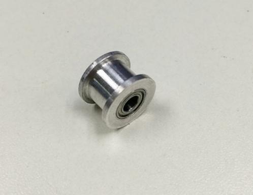
8 plates with 4 M10 nuts and M10 washers. * Tips: The Y-axis must be a rectangle, that is the rods on both side should be parallel, so is the front and rear plate. Otherwise it will cause obstruction for the belt later. 2.3Assemble the Y idler Note: as the driving wheel was added later, so in the video, there is some difference from what you get. But do not worry; it won t affect the whole process. Required parts Required number Part ID Pic Ball bearing 2 NO.36 bearing holder 1 NO.37 Driving wheel 1 NO.38 M4 x25 screw 1 NO.29 M4 lock nut 1 NO.13 Guide Block A 1 NO.A9 Guide Block B 1 NO.A10 M3 x 25screw 3 NO.23 M4x25 screw 1 NO.29 4
9 M3 wing nut M3 washer M3 nut M4 washer NO.14 NO.7 NO.11 NO.8 Step1. Amount guide block A and B onto the front support plate together, screw up it with 2 M3x25 screws, M3washers and M3 nuts. Note: the guide block B is close to front support plate. Step2. Thread a M3 x25screw and M3washer through the bearing holder. Step3. Insert the two MR84zz ball bearings into both ends of the driving wheel. 5

10 Step4. Put the M4 x25 screw and M4 washer through the driving wheel. Lock the other end with a M4 lock nut. You may need a wrench to tighten locking nut. 6
11 *Do not screw it too tight, you should leave enough room for the wheel to turn freely. Step5. Mount the assembled bearing holder through the guide blocks onto the front 7


12 support plates. And screw it with a wing nut. *Please leave enough room for the belt between the ball bearing and the screw Mount the Y motor Required parts Required number Part ID Pic Y motor fixed plate 1 NO. A8 Stepper motor 1 NO.57 pulley 1 NO.36 M3 x 10screw 3 NO.19 M3x16screw 2 NO.20 M3 washer 5 NO.7 Step1. Mount the pulley on the motor shaft, one of the screws should be screwed on the cross section of the shaft. Screw it up tightly. Step2. Insert the motor block into the slot; you may need to use a little strength to do this. Then screw the motor on the Y motor fix plate with 3 M3 x 10 screws and M3washers Step3. Fix the block plate with 2 M3 x 16 screws and M3 washers. 8


13 3. Build the printing platform Shenzhen GETECH CO.,LTD Required parts Required number Part ID Pic Y building platform 1 NO.A7 Y belt mount 1 NO.39 SCS8UU linear bearing 4 NO.33 M3 x 10 screw 2 NO.20 M4x12 screw 16 NO.28 M3washer 18 NO.7 M4 washer 16 NO.8 Step1. Mount the belt mount on the bottom side of the platform with 2 M3 x 10 screws and M3washers. Step2. Mount the 4 SCS8UU linear bearing on the platform with 16 M4x12 screws and M4 washers on the same side with the belt-mount. 9
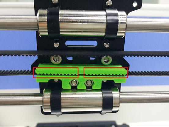
14 4. Assemble Y smooth rods Shenzhen GETECH CO.,LTD Required parts Required number Part ID Pic Y smooth rod 2 NO.3 Lock screw M3x4 mm 4 NO.30 Thread two smooth rods through: front side support [A2]> linear bearings > rear side support [A3] respectively. And screw it with 4 lock screws. When threading the rod, please make sure the holes are aligned and do not force it, or you will break the balls in the bearings. 5. Mount the Y-axis belt Required parts Required number Part ID Pic Timing belt 1 NO.42 M3 x 8 screw 2 NO.19 M3 washer 2 NO.7 Step1. Punch a hole on one end of the belt(the hole can be as the diameter of the M3 screw, leave enough margin ) Step2. Fix the belt on one side of the belt -mount with a M3 x 8 screw and washer. Step3. Thread the belt around the pulley on the motor and the Y idler. 10


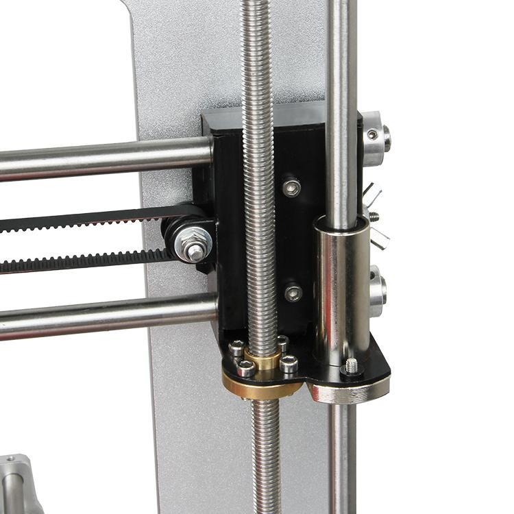
15 Step4. Punch a hole on the other end of the belt and fix it on the belt -mount with a M3 x 8 screw and M3 washer. *Tips: 1.Before you drill your second hole, make sure to pull belt tightly to make sure to find proper placement of hole for a tight belt, if it is too loose, it will hinder the move of t he print platform. 2. Loosen the Y idler wing nut when tightening belt onto the Y belt mount, in order to make securing the belt to the block easier. Be sure to tighten wing nut fully once done. 6. Assemble the Z-axis stepper motor, bottom mount and couplings Required parts Required number Part ID Pic X-Z frame 1 NO.A1 Z Motor fixed plate 2 NO. A5 Stepper Motor 2 NO.61 Coupling 2 NO.40 M3 x 16screw 4 NO.21 M3x10 screw 8 NO.20 M3 washer 12 NO.7 Step1. It would be easier to mount the motor on plates first, screw it with 8 11
16 M3x10screws and M3 washers Step2. Thread the wires of the motors through the hole. Mount the assembled motor to the X-Z frame (A1), and screw the X-Z frame with 4 M3 x 16screws and M3washers. Step3. Mount the coupling on the motor shaft, one of the screws should be screwed on the cross section of the shaft. Screw the small screw tightly. 7. Assemble Y - Z axis Required parts Required number Part ID Pic M3 x 16 screw 4 NO.21 M3 washer 4 NO.7 Step1. Held upright the X-Z frame on the threaded rods (Right after the Y connecting plate) Step2. Screw up the main frame to the Y connecting plate with 4 M3 x16 screws and M3 washers. 8. Attach the heated bed. Required parts Required number Part ID Pic Heat bed 1 NO.48 Borosilicate glass 1 NO.44 Spring 4 NO.31 12

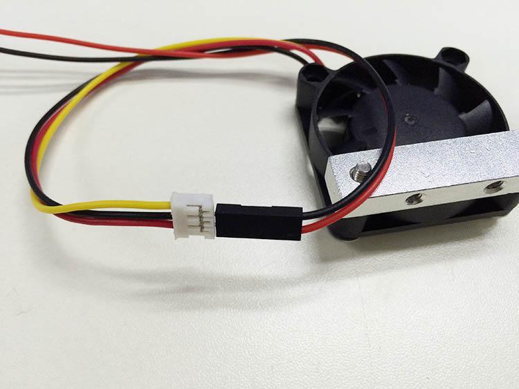
17 M3 washer M3 x30 screw 4 4 NO.7 NO.24 clamp 4 NO.45 Mount the heat bed on the platform with 4 M3 x30 screws and wing nuts with springs in between. Clamp the heat bed and the glass sheet. *Note The heating wire is pre-soldered on the bed and the thermometry wire is attached on the bed. The soldered side is better to be attached downwards. 9. Mount the fan Required parts Required number Part ID Pic 13


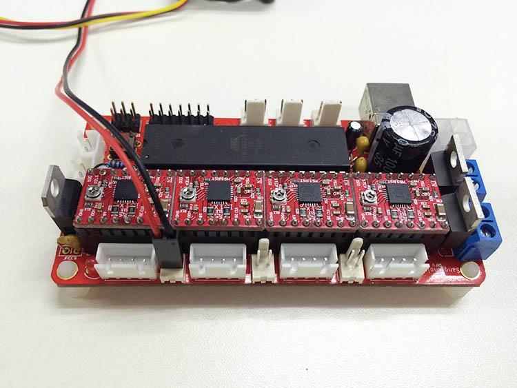
18 Fan M3 x 25screw 1 2 NO.47 NO.23 Fan mount M3washer 1 4 NO.A4 NO.7 M3 x 16screw 2 NO.21 Step1. Fix the fan on the fan mount with 2 M3 x 25 screws and M3washers. Step2. Mount the fixed block on the main frame with 2 M3x16 screws and M3 washers. *Mind the direction of the fan; it is blowing towards the board. 10. Mount the board on the left side panel of the printer Required parts Required number Part ID Pic Control board 1 NO.60 M3 x 20screw 4 NO.22 Spacer 4 NO.44 M3washer 4 NO.7 M3 nut 4 NO.11 Mount control board onto the back of X-Z frame, and screw up it with M3x20screws, M3washers and M3 nuts. 14


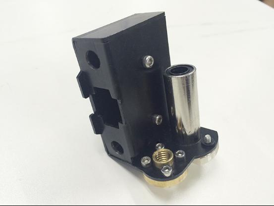
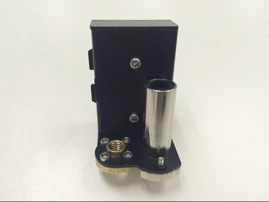
19 *Attention: The four A4988 stepper motor driver board is plugged on the board before shipping. The four spacers should between X-Z frame and control board. 11. Assemble the left end of the X axis(motor end) Mount the Z-axis nut, linear bearing Part name Part ID Required number pic Z-axis nut No.15 1 X-axis motor end No.M1 1 15
20 Linear Bearing LMH8LUU No M3 x 50 screw No.26 1 M3 x 6mm screw No M3 washer No. 7 2 \ Spring No Step1. Mount the Z nut on the X-axis left end from bottom to up, fix with M3 x 6mm screws. Step2. Mount the linear bearing on X-axis motor end from bottom to up. Fix it up with M3 x 6mm screws Mount the endstop trigger. 1. Thread a M3 washer> spring>m3 washer in order to the M3x50mm screw. 2. Thread half of the M3x50mm screw into the screw hole. 16

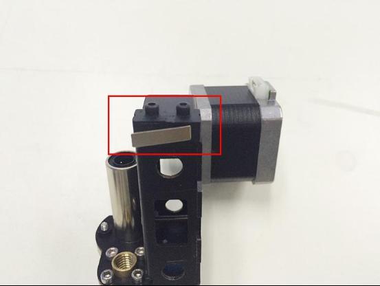
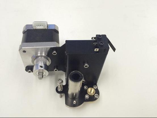
21 11. 3 mount the X motor. Part name Part ID Required number pic M3 x 6 mm screw No Stepper motor No.61 1 Pulley No.41 1 Step1. Mount the pulley on the motor shaft. Screw it on the flat side. 17


22 Step 2.Mount the stepper motor on the motor end with 3 M3 x 6 mm screw. 18

23 11.4 Mount the endstop Part name Part ID Required number pic M2.5 x 8 mm screw No End stop No.46 1 Mount the endstop on the top of X-axis motor end with 2 M2.5 x 8mm screws 19
24 20

25 12. Assemble the right end of the X axis. (X idler end) Part name Part ID Required number pic Z-axis nut No.15 1 X-axis idle end No.M2 1 Linear Bearing LMH8LUU No M3 x 6mm screw No.18 8 Step1.Mount the Z axis nut on the bottom of X-axis right end with 4 M3 x6mm screws. Step2. Mount the linear bearing on X-axis motor end from bottom to up. Fix it up with M3 x 6mm screws 21
26 22

27 13. Assembly of the extruder carriage Part name Part ID Required number pic X Carriage No.M3 1 Bearing Bracket No.M4 4 Extruder holder No.M5 1 Linear Bearing LM8LUU No.34 2 Belt bracket No.43 1 M3x6mm screw No M3x10mm screw No M4x6mm screw No M3 nut No.11 2 Step1. Fix the 4 Bearing Brackets on the back of the X Carriage loosely with M3x6mm screws. Insert the linear bearinginto the slot and screw the bracket tightly. 23

28 Please notice the front and back of the plate. Step2.fix the belt mount on the back of the carriage with 2 M3x 10mm screws and M3 hex nuts. Step3. Fix the extruder holder on the front side of the X carriage using M4x6mm screws. 24

29 14. Assemble the X&Z axis Part name Part ID Required number pic L300mm threaded rod L320mm smooth rod L390 mm smooth rod No.4 2 No.1 2 No.2 2 locking ring No.31 4 Step1. Thread the threaded rod to the nut of both end of X axis. 25

30 Keep both end of X axis at the same place of the rod, you are advised to measure the distance of the both side so that they are at the same level when you put them up. Step2. Plug the threaded rod on the X motor end to the left coupling on the left bottom of the Z axis. Then thread the 320mm smooth rod into the linear bearing. Step3. Thread the L390mm smooth rod into the X motor end >> thread the extruder carriage on the two rods Step4. Thread the two X axis smooth rods into the hole of X idler end. Step5. Plug the vertical threaded rod into the coupling on the right bottom of the Z axis. Then thread the 320mm smooth rod into the linear bearing. Step6. Thread 4 locking rings on the 2 rods separately.screw up the 4 locking rings. Note:the smooth rods and the threaded rod of Z axis are vertical and the X axis is horizontal, which is very important, or it will hinder the move of the Z axis. 26

31 15. Assemble the Z axis top mount Part name Part ID Required number pic Z top mount No.A6 2 M3 x 16mm screw No.21 4 Lock screw No
32 Step1. Add the Z top mount (No.A6) to the top of A1. Slowly rotate the rods into the holes, or add some lubricants on the rods. Do not force it, or u will break the acrylic piece. Step2. Screw it up with M3 x 16mm screw. Step3. Screw up the lock screwon both top and bottom of the smooth rods. 16. X belt driving wheel Part name Part ID Required number pic Driven wheel No.37 1 holder Driven wheel No.38 1 MR84zz Ball Bearing No.36 2 M3 x40mm screw No.25 1 M4 x 25mm screw No.29 1 M3 washer No.7 1 M4 washer No.8 1 M4 lock nut No.13 1 wing nut No.14 1 Step1. Thread the M3 x 40 screw and M3 washer through the Driven wheel holder. 28

33 Step2. Insert the two MR84zz ball bearingsinto both ends of the driving wheel. 29
34 30

35 Step3. Put the M4 x25 screw and M4 washerthrough the driving wheel. Lock the other end with a M4 lock nut. You may need a wrench to tighten locking nut. *Do not screw it too tight, you should leave enough room for the wheel to turn freely. 31
36 17. Add the belt Part name Part ID Required number pic Timing belt No.42 1 Belt bracket No.43 1 Step1. Insert one end of the belt in the groove. Pay attention to the tooth mesh of the belt and the groove. Step2. Thread another end of the belt through the X motor end around the pulley. Step3. Threaded the belt through the belt driving wheel and put the driving wheel into the X idler end, lock it with a wing nut. Step4. Insert another end of the belt into the groove. Cut the spare part. Be sure of the length of the belt. Step5. Taut the belt and tighten the wing nut on the idle end. 32
37 33


38 18. Mount the extruder Part name Part ID Required number pic Hotend No.59 1 M4x6mm screw No M4 washer No.8 1 Mount the hot end on the extruder holder plate from bottom to up with 2 M4x6mm screws and M4 washers 34


39 19. Mount the LCD panel Required parts Required number Part ID Pic LCD NO.62 Spacer 4 NO.44 knob 1 NO.51 35
40 M3washer 4 NO.7 M3 x 20 screw M3 nut 4 4 NO.22 NO.11 Mount the LCD into the top of main frame from back to front; screw it up with 4M3x16 screws, M3 washers and M3 nuts. *Note: Four spacers should between LCD and frame. 20. Mount the endstop of Y and Z axis Step1. End stop of Y-axis Required parts Required number Part ID Pic End stop 1 NO.46 M2.5 x 12 screw 2 NO.17 M2.5 washer 2 NO.6 Mount Y-axis end stop on the rear side support. Screw it up with M2.5x12 screws and M2.5 washers. Note: there is no + and - for endstop, so there is no difference for the wires. Step2. End stop of Z-axis Required parts Required number Part ID Pic 36

41 End stop 1 NO.46 M 2.5x 12 screw M2.5 washer 2 2 NO.17 NO.6 Mount Z-axis end stop on the left Z motor block. Screw up it with M2.5x12 screws and M2.5 washers. 21. Wiring Step1. Connect wires for motors. 1) Connect wires for X-axis motor. 37
42 2) Connect wires for Y-axis motor. 38

43 3) Connect wires for the 2 Z-axis motors. Here you need to use the NO.50 wire. 4) Connect Extruder motors 39

44 Step2. Connect heating wires. Loosed the screws in the blue terminal and put the red wires into the slot and screw it up. * There is no + and - polarityfor heating wires 1) Connect heating wires for heatbed. 40

45 2) Connect heating wires for extruder. 41
46 Step3. Connect wires for thermistor. 1) Connect wires for thermistor of heatbed. Shenzhen GETECH CO.,LTD 2) Connect wires for thermistor of extruder 42
47 Step4. Connect wires for endstop. * There is no + and - polarityforendstop 1) Connect wires for endstop of X-axis. 43
48 2) Connect wires for endstop of Y-axis. 44
49 3) Connect wires for endstop of Z-axis. Shenzhen GETECH CO.,LTD Step5. Connect wires for Fan. Note the + and - polarityfor fan Red: + Black: - Here you will need the 2-pin F-M extension wire for the fan. Connect the black and red wires to the connector of the fan wire. Leave the yellow wires alone. If your extension wire is 3-pin, it doesn t matter; just connect the black and red pins. 45

50 1) Connect fan for control board. 46
51 47

52 2) Connect fan for extruder. 48


53 Step6. Connect wires for LCD panel. 49

54 There are two cables, one is for LCD encoder, the other is for SD card. EXP1 to LCD EXP2 to SD card BTW, do you see the small screw above the SD card reader, if the text in of the LCD phases in an out or there is only blocks on the screen, you can adjust this screw to recovery it. Step7. Connect wires for power input. 50

55 Step8. Connect the wires to the PSU. 51

56 Note the correspondence between the color of wires and the connector. Brown------L Blue N Yellow------GND Red V Black------COM 22. Mount the filament spool. Part name Part ID Required number pic M3 x 16mm screw No.23 6 M3 Square nut No


57 M3 washer No.7 6 Spool base plate 1 Spool side pane 2 PVC tube 1 PVC tube 2 53

58 So far, the whole printer is built up, you can tidy up the wires with the zip ties and the coil wire. 23. Arrange the wires and tidy them up with the coil. The whole printer assembly work is already done. Hope you enjoy the whole process. So far, the whole printer is built up, you can tidy up the wires with the zip ties and the coil wire. 24. Tips Before even attempting the first print it is vital that the printer is correctly calibrated. Skipping or rushing this step will result in frustration and failed prints later, so it is important to take the time to make sure the machine is correctly set up. Each machine may have its own calibration procedure and this manual will not attempt to cover all the variations. Instead here is a list of key points that should be addressed. 54
59 Frame is stable and correctly aligned. Belts are taut. Bed is level in relation to the path of the extruder. Filament rolls freely from the spool, without causing too much tension on the extruder. Current for stepper motors is set to the correct level. Firmware settings are correct including: axis movement speeds and acceleration; temperature control; end-stops; motor directions. Extruder is calibrated in the firmware with the correct steps per mm of filament. The point regarding the extruder step rate is vital. Slic3r expects that the machine will accurately produce a set amount of filament when told to do so. Too much will result in blobs and other imperfections in the print, too little will result in gaps and poor inter-layer adhesion. 55
Assembly Instructions of Geeetech Prusa I3 A pro
 Assembly Instructions of Geeetech Prusa I3 A pro (Version 04-11-2016) CONTENT Safety Instructions... 3 Preparation... 4 1. Unfold the box and check the package... 1 2. Assemble Y axis... 1 3. Build the
Building Instructions of Geeetech Prusa I3 M201
 Building Instructions of Geeetech Prusa I3 M201 (Version 11-25-2016) CONTENT Safety Instructions... 1 Preparation... 2 1. Assemble the threaded rods of Y axis... 3 2. Assemble the front and back support
Building Instructions of Geeetech Prusa I3 M201
 Building Instructions of Geeetech Prusa I3 M201 (Version 04-11-2016) CONTENT Safety Instructions... 1 Preparation... 2 1. Assemble the threaded rods of Y axis... 3 2. Assemble the front and back support
Building Instruction of Geeetech Prusa I3 pro W. 3D Printer
 Building Instruction of Geeetech Prusa I3 pro W 3D Printer Version 05-31-2017 Contents Safety Instructions... 2 Preparations... 3 1.Unfold the box and check the package... 4 2 Assemble the rods of a Y
Assemble Manual of Geeetech Acrylic Prusa I3 (8mm)
") Assemble Manual of Geeetech Acrylic Prusa I3 (8mm) Warning: Shenzhen GETECH CO.,LTD. This kit contains tiny parts; please keep them away from kids under 3.. Building and operating 3D printer involves electricity,
Assemble Manual of Geeetech Acrylic Prusa I3 (8mm) Warning: Shenzhen GETECH CO.,LTD. This kit contains tiny parts; please keep them away from kids under 3.. Building and operating 3D printer involves electricity,
Delta Rostock mini G2S Pro 3D Printer
 Delta Rostock mini G2S Pro 3D Printer Copyright Declaration The copyright of this manual belongs to the Shenzhen GETECH CO., LTD. (hereinafter referred to as the "Geeetech"), and all rights reserved. No
Geeetech Prusa I3 M201
 Geeetech Prusa I3 M20 Copyright Declaration The copyright of this manual belongs to the Shenzhen GETECH CO., LTD. (hereinafter referred to as the "Geeetech"), and all rights reserved. No part of this specification
Geeetech Prusa I3 M201. Assembly Manual
 Geeetech Prusa I3 M20 Assembly Manual SUPPORT Thanks for choosing Geeetech, we strive to provide a satisfied and pleasant shopping experience for you, but we do understand there may be some questions you
Copyright Declaration
 Geeetech Prusa I3 X Copyright Declaration The copyright of this manual belongs to the Shenzhen GETECH CO., LTD. (hereinafter referred to as the "Geeetech"), and all rights reserved. No part of this specification
Prusa i3 Printer Assembly Guide
 Prusa i3 Printer Assembly Guide Special thanks to Carlos Sanchez and Miguel Sanchez for the graphics. All graphics captured from their great animation: http://www.carlos-sanchez.com/ Prusa3/ For copyright
5. Extruder Assembly
 5. Extruder Assembly Guide for the assembly of the Extruder. Written By: Josef Prusa 2018 manual.prusa3d.com/ Page 1 of 24 Step 1 Get the necessary tools 2.5 and 1.5 mm Allen key Needle-nose pliers 2018
3. Extruder Assembly
 3. Extruder Assembly Guide for the assembly of the Extruder. Written By: Josef Prusa 2017 manual.prusa3d.com Page 1 of 22 Step 1 Get the necessary tools 2.5 and 1.5 mm Allen key Needle-nose pliers Step
TL4076 Top 5 Tips Get to know your TL4076
 TL4076 Top 5 Tips Get to know your TL4076 Thermal Break with Teflon liner (behind fan) Hot End Assembly Fan Heat Block Extruder with toothed gear(brass) and idler (steel) Filament Guide Tube Nozzle Cable
Upgrade v3 to v3.2. SeeMeCNC Guides. Upgrade v3 to v3.2. Rostock Max v3 Uprgade to v3.2. Written By: SeeMeCNC seemecnc.dozuki.
 SeeMeCNC Guides Upgrade v3 to v3.2 Rostock Max v3 Uprgade to v3.2 Written By: SeeMeCNC 2018 seemecnc.dozuki.com/ Page 1 of 34 INTRODUCTION This guide is intended to Upgrade a Rostock Max v3 to a Rostock
8. Electronics assembly (B3/R2 design)
") 8. Electronics assembly (B3/R2 design) Written By: Jakub Dolezal 2018 manual.prusa3d.com/ Page 1 of 31 Step 1 Tools necessary for this chapter Needle-nose pliers for zip tie trimming. 2.5mm Allen key for
8. Electronics assembly (B3/R2 design) Written By: Jakub Dolezal 2018 manual.prusa3d.com/ Page 1 of 31 Step 1 Tools necessary for this chapter Needle-nose pliers for zip tie trimming. 2.5mm Allen key for
Pi Instruction Manual. Mechanical
 Pi3 2014 Instruction Manual Document No MANUAL WBS Pi3 2014 DIY REV01 Mechanical 3D LabteK Model 1 / 37 Content Page Introduction 2 Printed Parts 3 1, Mechanical 4 1,1 Frame Assembly 6 1,2 Y Axis Assembly
5. E-axis assembly. 5. E-axis assembly. Written By: Jakub Dolezal manual.prusa3d.com/ Page 1 of 40
 5. E-axis assembly Written By: Jakub Dolezal 2018 manual.prusa3d.com/ Page 1 of 40 Step 1 Tools necessary for this chapter Needle-nose pliers for zip tie trimming. 2.5mm Allen key for M3 screws 2mm Allen
Modix Big-60 Assembly Manual Part 2
 Modix Big-60 Assembly Manual Part 2 Version 1.0, October 2017 Menu 1. Motors & End Stop Wiring... 3 2. Controller Wiring Check... 6 3. Extruder Wiring... 7 4. Electronic Box Cover... 9 5. Filament Sensor...
TeeBox. The Suitcase 3D printer. BY:
 TeeBox The Suitcase 3D printer. BY: Eindhoven The Netherlands Contents Liability... 2 Returns... 2 WARNING... Error! Bookmark not defined. TRICKS AND TIP... 4 PART 1 ---Y AXIS (PRINT BED)... 7 Fasten heatbed
Written By: Josef Prusa
 7. PSU & Heatbed assembly PSU and Heatbed guide Written By: Josef Prusa 2017 manual.prusa3d.com/ Page 1 of 17 Step 1 Getting the necessary tools 2 and 2.5 mm allen key Needle-nose pliers Step 2 3D printed
Modix Big-60 Assembly Instructions Part 1
 Modix Big-60 Assembly Instructions Part 1 Version 1.0, October 2017 Menu 1. X Idler Pulley Assembly... 3 2. Connecting X Axis Brackets to Z Profiles... 4 3. Assemble X Rails on X Top Profiles... 6 4. Assemble
2. Multiplexer assembly
 2. Multiplexer assembly Written By: Jakub Dolezal 2017 manual.prusa3d.com/ Page 1 of 15 Step 1 Parts identification Y-splitter (new version) - QSM fittings and steel tubes are assembled in the factory.
To be the Chief Evangelist CR-10S Pro Printer Guide Book To make Top-quality 3D printer
 To be the Chief Evangelist CR-0S Pro Printer Guide Book To make Top-quality 3D printer This guide book is for standard CR-0S Pro. Please plug the power cord into a three-hole power jack. Detailed instructions
ASSEMBLY MANUAL TINKERINE STUDIO. 3D Printer + Creative Solution
 + ASSEMBLY MANUAL 3D Printer + Creative Solution CONTENTS Safety Instructions Ditto at a Glance Bill of Materials Before You Start Z-Platform Ditto Frame pt.1 Ditto Frame pt.2 Gantry pt.1 Gantry pt.2 Gantry
JGAURORA 3D PRINTER MODEL: A5 USER GUIDE
 JGAURORA 3D PRINTER MODEL: A5 USER GUIDE Contents ----3D Printer User Guide 1. Preface... 2 1.1 Introduction...2 1.2 Safety advice... 2 1.3 Filament requirements...2 1.4 Environmental requirements...2
3. X-axis assembly. 3. X-axis assembly. X axis guide. Written By: Josef Prusa manual.prusa3d.com/ Page 1 of 14
 3. X-axis assembly X axis guide Written By: Josef Prusa 2017 manual.prusa3d.com/ Page 1 of 14 Step 1 Getting the necessary tools 1.5mm & 2.5mm Allen key Needle-nose pliers Step 2 3D printed parts X-carriage
3D PRINTER USER MANUAL
 3D PRINTER USER MANUAL Table of contents page: 1. Introduction 2. Table of contents 3. Basic informations 4. General information 5. Glossary 6. Starter pack s content 7. Technical parameters 8. Device
Important notice Upper supports for Z axis Pulley Corner for Y axis Right X axis and left X axis Chain coupling for left X axis
 Warranty and FAQ G004260 Important notice You can personalise your Prusa i3 HEPHESTOS and update it with the latest innovations that appear in the community. However, it is important that you understand
M2 Wiring. Table of Contents
 M2 Wiring Table of Contents M2 Wiring Harness... 2 RAMBo... 3 Wire Harness 1... 4 Wire Harness 2... 5 Wire Harness 3... 6 Wire Harness 4... 7 Wire Harness 5... 8 Connecting Wiring Harness to M2 Printer...
SeeMeCNC Guides. Orion Delta HE280 Hotend Upgrade. This How-to Guide will walk you through the steps of upgrading to the HE280 Hotend
 SeeMeCNC Guides Orion Delta HE280 Hotend Upgrade This How-to Guide will walk you through the steps of upgrading to the HE280 Hotend Written By: JJ Johnson 2017 seemecnc.dozuki.com Page 1 of 18 INTRODUCTION
CONTENTS. Safety Instructions. Litto at a Glance. Bill of Materials. Before You Start. Z-Platform. Litto Frame pt.1. Litto Frame pt.2. Gantry pt.
 ASSEMBLY MANUAL CONTENTS Safety Instructions Litto at a Glance Bill of Materials Before You Start Z-Platform Litto Frame pt.1 Litto Frame pt.2 Gantry pt.1 Gantry pt.2 Gantry pt.3 Carriage Electronics /
6. Pre-print checks. 3D Touch
 Page 1 1. 6. Pre-print checks........................................................................................... 1.1 a. Clearing the print bed..................................................................................
Documentation version ASSEMBLY INSTRUCTIONS
 Documentation version 1.6.30 ASSEMBLY INSTRUCTIONS / 2 INTRODUCTION / 3 INTRODUCTION Target : Propose a visual assembly instruction guide of the MicroDelta Rework. Designers of the MicroDelta Rework :
Installation Instruction of CTC DIY 3D Printer
 Installation Instruction of CTC DIY 3D Printer Focus on high-end science and technology,focus on 3D printing Zhuhai CTC Electronics Co.,Ltd. www.ctcprinter.com 1 Introduction This DIY 3D printer can be
Documentation version 1.42 ASSEMBLY INSTRUCTIONS REV 1.1
 Documentation version 1.42 ASSEMBLY INSTRUCTIONS REV 1.1 / 2 INTRODUCTION / 3 INTRODUCTION Target : Prupose a visual guide of the differents steps to build and use a µdelta printer Designers : Hugo Flye
WANHAO Duplicator i3. User Manual V1.2. Wanhao USA
 WANHAO Duplicator i3 User Manual V1.2 Wanhao USA 2015 www.wanhaousa.com Safety WARNING: The components on the Duplicator i3 generate high temperatures and move extremely fast. Reaching inside of the Duplicator
K Wiring and Electronics
 HKBay.com K Wiring and Electronics Written By: HKBay 2017 hkbay.dozuki.com Page 1 of 12 TOOLS: Hex key; ball ended, long arm, 2.5mm (1) PARTS: Arduino Mega (blue) (1) RAMPS board (red) (1) glass tabs (3)
3D TOUCH. Extruder upgrade. Document version 1.0
 3D TOUCH Extruder upgrade Document version 1.0 1 Summary This manual is for the installation of an additional extruder into the 3D Touch. The procedure is the same for both 1 2 head, and 2 3 head upgrades.
Maker's Tool Works. Written By: Micro. Wiring methods used by MTW Printers using the Rambo Electronics. Wiring Rambo Electronics & Power Supply
 Maker's Tool Works Wiring Rambo Electronics & Power Supply Wiring methods used by MTW Printers using the Rambo Electronics. Written By: Micro 2017 mtw.dozuki.com Page 1 of 10 TOOLS: Screw Drivers (1) Wire
How this (and most) 3D Printers work. Forward
 3D Printers work. Forward") Build Manual Contents Contents Contents 2 Forward 4 How this (and most) 3D Printers work. 5 3D Printing Workflow 6 Space to work 7 Tools / Parts Required 7 Build Time 8 How To Use This Manual 8 Acrylic
Build Manual Contents Contents Contents 2 Forward 4 How this (and most) 3D Printers work. 5 3D Printing Workflow 6 Space to work 7 Tools / Parts Required 7 Build Time 8 How To Use This Manual 8 Acrylic
Quick Starter Manual for PrusaM201
 Quick Starter Manual for PrusaM201 Copyright Declaration The copyright of this specification belongs to the Shenzhen GETECH CO., LTD. (hereinafter referred to as the "Geeetech"), and all rights reserved.
Documentation version ASSEMBLY INSTRUCTIONS
 Documentation version 1.1.0 ASSEMBLY INSTRUCTIONS / 2 INTRODUCTION / 3 INTRODUCTION Target : Provide a visual guide of the various steps required to assemble the «i3 Metal Motion» 3D printer. Designers
5. Extruder. 5. Extruder. Extruder guide. Written By: Dozuki System manual.prusa3d.com Page 1 of 16
 5. Extruder Extruder guide Written By: Dozuki System 2017 manual.prusa3d.com Page 1 of 16 Step 1 Get the necessary tools 2.5, 2 and 1.5 mm hex spanner Needle-nose pliers Step 2 3D printed parts Extruder
Introduction to 3D Printing
 TAKE HOME LABS OKLAHOMA STATE UNIVERSITY Introduction to 3D Printing by Sean Hendrix 1 OBJECTIVE The objective of this experiment is to introduce you to 3D printing, by having you print some simple parts
Bondtech for Prusa i3
 Bondtech for Prusa i3 Assembly and installation manual This work is licensed under a GNU General Public License v3.0 Table of Contents Acknowledgements 1 Introduction 1 Compatibility 2 What s in the box?
Maintenance Manual. Hephestos
 Hephestos 2016 Mundo Reader SL. All rights reserved. The reproduction, copying, distribution, publication or modification of this material is strictly prohibited unless carried out with the express prior
FlexJet - Flex Cable Replacement
 P/N: 109515R0 14140 NE 200th St. Woodinville, WA. 98072 PH: (425) 398-8282 FX: (425) 398-8383 FlexJet - Flex Cable Replacement Notices: Warning! Ensure that all AC power cables are removed from the printer
Please read the safety instructions carefully before get started.
 Safety Instructions Please read the safety instructions carefully before get started. ANYCUBIC 3D printer generates high temperature. Do not reach inside of the printer during operation. Allow time for
Witbox 2. Quick start guide
 Witbox 2 Quick start guide Welcome. Thank you for choosing us. This manual will help you to use your new 3D printer correctly. Welcome to the world of Witbox 2. How do I use this manual? To make sure that
OLYMPIAN MODEL 740 Operation and Service Manual
 OLYMPIAN MODEL 740 Operation and Service Manual P/N 133911-102 FCI MANUAL P/N 133865-001 Data herein has been verified and validated and believed adequate for the intended use. If the machine or procedures
Electronics. Electronics docs.imade3d.com/ Page 1 of 15
 Electronics 2018 docs.imade3d.com/ Page 1 of 15 Step 1 Wire Comb 4" zip ties Wire comb Step 2 Align the wire comb with the corresponding annotations (ie. filament fan, heat block, etc.), and secure it
Assembly and User Manual
 Champion LEVEL 1 Assembly and User Manual Page 1 clearaudio electronic GmbH 2006 DEAR AUDIO ENTHUSIAST Thank you for your decision to purchase a clearaudio Champion Level 1 turntable. This turntable is
ustepper - Robot Arm Assembly instructions Microcontroller, stepper driver and encoder in an ultra-compact design! By ON Development IVS
 ustepper - Robot Arm Assembly instructions Microcontroller, stepper driver and encoder in an ultra-compact design! By ON Development IVS 2016 ON Development IVS All Rights Reserved Assembly notes The parts
1 COPPERHEAD 3D PRINTER ASSEMBLY GUIDE WELCOME
 1 COPPERHEAD 3D PRINTER ASSEMBLY GUIDE WELCOME Thank you for choosing the Copperhead 3D printer from Acadian Robotics. Please read through this manual first before setting up your machine. If you have
SERIES A & AA ROLLER DOORS INSTALLATION GUIDE
 SERIES A & AA ROLLER DOORS INSTALLATION GUIDE THESE INSTRUCTIONS ARE PROVIDED FOR USE BY EXPERIENCED INSTALLERS OF GARAGE DOORS BY UNDER-TAKING THE INSTALLATION OF THIS DOOR, THE INSTALLER UNDERSTANDS
RS4000 Setup. Before you install the RS4000 system, check to ensure that nothing was damaged or lost during shipping.
 RS4000 Setup Before you install the RS4000 system, check to ensure that nothing was damaged or lost during shipping. If anything is damaged or missing, contact your salesman immediately. Mount Components
RockyHydro. System Assembly Info Packet
 RockyHydro System Assembly Info Packet RockyHydro sells a wide degree of micro-hydro components for various kits. Our customers enjoy the benefit of being able to carefully match a turbine and generator
Operating Manual. D3D Innovations Limited. 7 Kings Road, Wrington, Bristol, BS40 5LW, UK.
 Operating Manual FILAMENT WINDER D3D Innovations Limited 7 Kings Road, Wrington, Bristol, BS40 5LW, UK www.filafab.co.uk www.d3dinnovations.com www.filafab.co.uk Copyright 2016 by D3D Innovations Limited
Overview of EIS Installation
 Overview of EIS Installation Thank you for purchasing an Electroair Ignition System for your aircraft. We are confident that you will be happy with the performance of your EIS on your aircraft. The next
UM3 Spare Parts Ultimaker 3 Spare-Parts Version /06/18
 Ultimaker 3 Spare-Parts Version 1.2 13/06/18 Housing 1156 Z-Shaft Cap Bottom 1901 Controler Electronics Cover 1902 Main Board Electronics Cover 1903 Cable Cover 1904 Wifi Cover 1905 Print Table Back Cover
Air Oil Separator for WRX
 Air Oil Separator for 2015+ WRX 2018-06-05 Thank you for purchasing this PERRIN product for your car! Installation of this product should only be performed by persons experienced with installation of aftermarket
Building Instructions Upside Variable Pitch Prop System
 Building Instructions Upside Variable Pitch Prop System it s tim o e t fly! Thank you for buying our revolutionary UPSIDEDOWN VP-Prop System! Experience a new dimension in 3D performance. Assembly and
Assembly of the Electronics
 6 ssembly of the Electronics List of components for the Electronics Ramps 1.4 (with 4 x mounted Stepstick Drivers 4988) 3 x Endstop LD control panel 1.8 m type US cable 4 x Nema 17 motor cable 2 x 40 cm
Front Drive System - Big Block Chevy Installation Instructions Big Block Chevy with AC & with PS
 Front Drive System - Big Block Chevy Installation Instructions Big Block Chevy with AC & with PS All American Billet Store (800) 764-0926 www.allamericanbilletstore.com Items needed for install Jack Jack
Automatic Roof Hatch Opener
 Automatic Roof Hatch Opener Installation Guide REQUIRED TOOLS (These tools are required to complete the installation) Cordless Drill 1/8 1/4 Drill Bits 1/8 Pin Punch #2 Philips Bit Rachet Sharpie Hammer
JEEVES. JEEVES Installation Manual. Installation Manual The Easiest Do-It-Yourself Dumbwaiter on the Market
 1 888-323-8755 www.nwlifts.com JEEVES Installation Manual The Easiest Do-It-Yourself Dumbwaiter on the Market This manual will cover the installation procedure step-by-step. The installation of this dumbwaiter
3D PRINTER. Pack 09. Anything you can imagine, you can make! 3D technology is now available for you at home! BUILD YOUR OWN
 BUILD YOUR OWN Pack 09 Anything you can imagine, you can make! 3D PRINTER Compatible with Windows 7 & 8 Mac OS X 3D technology is now available for you at home! www.model-space.com BUILD YOUR OWN 3D PRINTER
Assembly Manual FELIX One
 Assembly Manual FELIX One Version 1.0 2018 www.felixprinters.com support@felixprinters.com Zeemanlaan 15 3401 MV IJsselstein The Netherlands Introduction Table of Content Dear Customer, Thank you for choosing
GS5 GYM MULTI STATION USER MANUAL
 GS5 GYM MULTI STATION USER MANUAL Product may vary slightly from the item pictured due to model upgrades Read all instructions carefully before using this product. Retain this owner s manual for future
Heated Bed Installation Instructions
 Heated Bed Installation Instructions Overview The glass panel is heated by way of a heater element which is bonded to the glass panel and controlled by a digital temperature controller. The temperature
The H-MAC Heavy Metal Articulating Chassis Construction Guide
 The H-MAC Heavy Metal Articulating Chassis Construction Guide The Heavy Metal Chassis is constructed with two identical drive modules built using 10 mechanical sub-assemblies. The drive modules are integrated
Written By: Jakub Dolezal
 7. Heatbed & PSU assembly (spiral wrap) Written By: Jakub Dolezal 2018 manual.prusa3d.com/ Page 1 of 17 Step 1 Tools necessary for this chapter Before you start, make sure you are in the right chapter!
EZ-Glide Wheels Installation Patent Pending Revised 8/23/2011
 EZ-Glide Wheels Installation Patent Pending Revised 8/23/2011 Questions: Lakeside Quilt Co. Jack Boersma Toll Free (888) 361-4806 www.lovetoquilt.com Cell (406) 270-4715 sales@lovetoquilt.com Toll Free
160S Rewind Option Kit Installation Instructions
 Installation Instructions GENERAL This kit includes the parts and documentation necessary to install the Media Rewind Option into the Zebra 160S printer. Read these instructions thoroughly before attempting
General Information. Notations and Conventions. Compatibility Check. Kit Description. Call-Outs. Part Lists Great Plains Manufacturing, Inc.
 Part Lists Great Plains Manufacturing, Inc. 1 Installation Instructions Loup Shaft Monitor Used with Drill models: Compatible with most 1995 and later, two- and three-box drills with 5 8 -inch square main
TRIPODMAKER BLACK EDITION USER MANUAL
 TRIPODMAKER BLACK EDITION USER MANUAL TABLE OF CONTENT Specifications and box content 1. Specifications of the Tripodmaker...4 2. Box content...5 3. Terminology...6 4. Attentions and warnings...8 Unboxing
Assembly Manual FELIX Tec 4
 Assembly Manual FELIX Tec 4 Version 5.2 2018 www.felixprinters.com support@felixprinters.com Zeemanlaan 15 401 MV IJsselstein The Netherlands Introduction Table of Content Dear Customer, Thank you for
NWA3D A5 User Manual
 1. NWA3D A5 3D Printer Part Diagrams 2. Assembling the Spool Holder 3. Leveling the Build Plate 4. Loading and Unloading Filament 5. Operation: The Four Steps in 3D Printing 6. Troubleshooting 7. Additional
Service menu - Individual Filament Calibration
 Service menu - Individual Filament Calibration Written By: Jakub Dolezal 2018 manual.prusa3d.com/ Page 1 of 8 Step 1 Introduction This guide will take you through the calibration of the Bowden length on
Assembly of the Electronics
 6 ssembly of the Electronics List of components for the Electronics Ramps 1.4 (with 4 x Stepstick Drivers 4988 mounted) 3 x Endstop LD control Panel US cable, type, 1.8 metres 4 x Nema 17 motor cable 2
How To: Fix That Ugly Hanging E-Brake Cable A CFans Members Mod Project by dirtydawg
 How To: Fix That Ugly Hanging E-Brake Cable A CFans Members Mod Project by dirtydawg Skill Level: Easy Disclaimer: Please use caution and seek professional assistance when necessary. ColoradoFans.com,
INSTALLATION INSTRUCTIONS
 INSTALLATION INSTRUCTIONS WARNING: NEVER EXCEED YOUR VEHICLE MANUFACTURER'S RECOMMENDED TOWING CAPACITY A20 5TH WHEEL HITCH TABLE OF CONTENTS Page# Description 1 Warnings & Precautions 2 - Assembly & Installation
How to Build with the Mindstorm Kit
 How to Build with the Mindstorm Kit There are many resources available Constructopedias Example Robots YouTube Etc. The best way to learn, is to do Remember rule #1: don't be afraid to fail New Rule: don't
Assembly Manual. 1/10th Formula 1 Car
 Assembly Manual 1/10th Formula 1 Car Center Pivot Bag 1 3374 - Center Pivot Socket 40194 - Hard Anodized Alum Pivot ball 3254-2-56 *Note - Sometimes it is helpful to slightly over-tighten the top clamp
Installation and Operation Manual. Manufacturers of Innovative Materials Handling Equipment since 1957.
 SWINGSET DISTRIBUTOR Installation and Operation Manual Manufacturers of Innovative Materials Handling Equipment since 1957. 491 North Emerson Street * Cambridge MN 55008-1316 U.S.A. Toll Free (800) 328-8002
LS Style Track Alt/AC Serpentine Kit Kit # (Standard Mount Electric Throttle Body Kit) Kit # (Narrow Mount Mechanical Throttle Body Kit)
 Kit # (Narrow Mount Mechanical Throttle Body Kit)") 12/08/16 LS Style Track Alt/AC/PS Serpentine Kit Kit # 20060 (Standard Mount Electronic Throttle Body Kit) Kit # 20065 (Narrow Mount Mechanical Throttle Body Kit) LS Style Track Alt/AC Serpentine Kit Kit
12/08/16 LS Style Track Alt/AC/PS Serpentine Kit Kit # 20060 (Standard Mount Electronic Throttle Body Kit) Kit # 20065 (Narrow Mount Mechanical Throttle Body Kit) LS Style Track Alt/AC Serpentine Kit Kit
Trifecta 800 3D Printer. User s Guide
 Trifecta 800 3D Printer User s Guide Table of Contents 3 SAFETY WARNINGS 4 WARRANTY 5 SPECIFICATIONS 6 PRINTER OVERVIEW 7 UNBOXING 9 10 11 12 13 14 15 17 18 20 22 25 26 FILAMENT INSTALLATION PRINT BED
Physics 144 Chowdary How Things Work. Lab #5: Circuits
 Physics 144 Chowdary How Things Work Spring 2006 Name: Partners Name(s): Lab #5: Circuits Introduction In today s lab, we ll learn about simple electric circuits. All electrical and electronic appliances
The HMC Heavy Metal Chassis Construction Guide
 The HMC Heavy Metal Chassis Construction Guide The Heavy Metal Chassis is constructed using two identical drive modules. The drive modules are constructed using 4 mechanical sub-assemblies. The drive modules
Desktop 5.5 Z Axis Retrofit
 Page 1 Kit parts Desktop 5.5 Z Axis Retrofit Carriage plate with stop bolt and Z proximity switch installed Zip ties Spare bolts Spindle mounting plate with stop bolt, spring mount, and rail Z proximity
Assembly instructions. Veranda sunblind VZ510. art.nr
 Assembly instructions Veranda sunblind VZ510 art.nr. 27807 A. Introduction: Assembly instructions Veranda sunblind VZ510 This assembly guide is available from 15-11-00 and is directed to qualified assemblers.
Zesty Technology Documentation
 Zesty Technology Documentation Release 0.1 Brian Gilbert Sep 23, 2018 Nimble Documentation: 1 Nimble 1 2 Sidewinder 13 3 Printer specific instructions 25 4 Nimble Adapters 47 5 Maintenance of your Nimble
911-FPR Fuse Panel Installation Guide. Issue 1.3
 911-FPR Fuse Panel Installation Guide Issue 1.3 Thanks! Thank you for purchasing our fuse panel upgrade for your 911. We hope you like it! The fuse panel is just one of many products we are developing.
S1 Sequential. T56 Magnum. Sequential shifter. Contents and assembly instructions
 S1 Sequential Sequential shifter T56 Magnum Contents and assembly instructions Parts List Sequential shifter x1 Base plate x1 Base spacer x1 Drill Square x1 Shaft fitting x1 Square washer x1 8mm Aluminium
GPS AutoSteer System Installation Manual
 GPS AutoSteer System Installation Manual John Deere MFWD AutoTrac Ready Supported Models 8225R 8245R 8270R 8295R 8320R 8345R PN: 602-0254-01-A LEGAL DISCLAIMER Note: Read and follow ALL instructions in
3D PRINTER. Pack 10. Anything you can imagine, you can make! 3D technology is now available for you at home! BUILD YOUR OWN
 BUILD YOUR OWN Pack 10 Anything you can imagine, you can make! 3D PRINTER Compatible with Windows 7 & 8 Mac OS X 3D technology is now available for you at home! BUILD YOUR OWN 3D PRINTER CONTENTS PACK
Permanent Magnetic Linear Generator Project Prototype (This Material was Produced by Oregon State University s Energy Systems Group)
") Permanent Magnetic Linear Generator Project Prototype (This Material was Produced by Oregon State University s Energy Systems Group) This Permanent Magnet Linear Generator (PMLG) prototype was developed
Permanent Magnetic Linear Generator Project Prototype (This Material was Produced by Oregon State University s Energy Systems Group) This Permanent Magnet Linear Generator (PMLG) prototype was developed
VARIFUEL MAINTENANCE AND REPAIR INSTRUCTIONS
 VARIFUEL2 200-120 MAINTENANCE AND REPAIR INSTRUCTIONS MOTORTECH Gas Regulation P/N 01.50.008-200-120-EN Rev. 06/2015 Copyright Copyright 2015 MOTORTECH GmbH. All rights reserved. Distribution and reproduction
20 TONNE HYDRAULIC PRESS MODEL NO: CSA20FBT
 20 TONNE HYDRAULIC PRESS MODEL NO: CSA20FBT PART NO: 7614058 OPERATION & MAINTENANCE INSTRUCTIONS WARNING: Read these instructions before using the press GC0516 INTRODUCTION Thank you for purchasing this
Steeda Sport Mustang Lowering Springs (2005+) - Installation Instructions
 - Installation Instructions") Steeda Sport Mustang Lowering Springs (2005+) - Installation Instructions The below installation instructions work for the following products: Steeda Sport Mustang Lowering Springs (2005+) Please read
Steeda Sport Mustang Lowering Springs (2005+) - Installation Instructions The below installation instructions work for the following products: Steeda Sport Mustang Lowering Springs (2005+) Please read