Building Instructions of Geeetech Prusa I3 M201
|
|
|
- Nora Elizabeth Cummings
- 6 years ago
- Views:
Transcription

1 Building Instructions of Geeetech Prusa I3 M201 (Version )
2 CONTENT Safety Instructions... 1 Preparation Assemble the threaded rods of Y axis Assemble the front and back support of y axis Thread the smooth rods and linear bearings Mount the Y motor Y belt driving wheel Build the print platform Mount the Y belt Right Z motor mount Left Z motor mount Side panel assembly Main frame assembly Fan mount Mount the Z endstop Mount the Z motors Mount the couplings Mount the building platform Assemble the left end of the X axis(motor end) Assemble the right end of the X axis. (X idler end) Assembly of the extruder carriage Assemble the the X&Z axis Assemble the Z axis top mount X belt driving wheel Add the belt Mount the hotend Mount the extruders Mount the LCD panel Mount the control board Mount the power supply unit(psu ) and the socket Mount the Y endstop Wiring Mount the filament spool
3 Safety Instructions Building the printer will require a certain amount of physical dexterity, common sense and a thorough understanding of what you are doing. We have provided this detailed instruction to help you assemble it easily. However ultimately we cannot be responsible for your health and safety whilst building or operating the printer, with that in mind be sure you are confident with what you are doing prior to commencing with building or buying. Read the entire manual to enable you to make an informed decision. Building and operating involves electricity, so all necessary precautions should be taken and adhered to, the printer runs on 12V supplied by a certified power supply, so you shouldn t ever have to get involved with anything over 12V but bear in mind there can still be high currents involved and even at 12V they shouldn t be taken lightly. High temperatures are involved with 3D Printing, the Extrusion nozzle of the hot end can run about 230 C, the heated bed runs 110 C and the molten plastic extruded will initially be at around 200 C, so special care and attention should be made when handling these parts of the printer during operation. We wouldn t recommend leaving your printer running unattended, or at least until you are confident to do so. We cannot be held responsible for any loss, damage, threat, hurt or other negligent result from either building or using the printer. 1
4 Preparation 1. Unpack the kit and check if all parts are in the box and check the condition of each part, there might be some damage during shipping. To help you with this, there is BOM in the box and each bag was labeled with part number. 2. Contact our customer service immediately by or through the website if you find any missing or damaged parts. And on the bottom of the BOM, there is a signature of reviewer, please take a picture of it and attach the picture in your mail. 3. Read through each chapter of these instructions to gain an over-all idea of what is involved and how long it might take, before starting on the work described. Or you can watch the video here. 4. Before you start, you can put all the part in order to save your time especially those screws and nuts. Do not mix them up. 5. Some printed parts may need more filing than others to ensure a secure fit when screwing together. Please do not over file a part, it is best to remove a small amount of excess plastic and test the fit then re-file as necessary. No excessive forces should be required to bring parts together. 6. Ensure you have the necessary skills to carry out the work, or enlist the help of someone who does. 7. Work on a big firm table or bench in a clean dry well-lit area. 8. This kit contains tiny parts; please keep them away from kids under Ask for help if you run into any problems - our contact details are on the website and we will always do our best to resolve any problems encountered. 2


5 1. Assemble the threaded rods of Y axis Shenzhen GETECH CO.,LTD Part name Part ID Required number pic 450 mm threaded No.5 2 rod M10 washer No.9 8 M10 hex nut No.13 8 M10 spring washer No.10 6 Connecting fender No.A14 2 Thread the nuts and washers into the two M10 threaded rods separately. Watch the Video here. 2. Assemble the front and back support of y axis. 3
6 Part name Part ID Required number pic M10 washer No.9 4 M10 hex nut No.13 4 Y axis front No.A9 1 support Y axis front No.A10 1 support Y axis rear support No.A11 1 Y axis rear support No.A12 1 Thread the plate to both end of the threaded rod in the following order:2 Front outside support plate: No.A9 Front inside support plate: No.A10 Rear outside support plate: No.A12 Rear inside support plate: No.A11 Screw up the threaded rods and support plates with M10 nut and M10 washer at both end. Hand tighten the M10 Nuts against the M10 Washers. Try to keep the rods parallel and the four acrylic pieces parallel. 4


7 * Tips: the Y-axis must be a rectangle, that is the rods on both side should be parallel, so is the front and back plate. Otherwise it will cause obstruction for the belt later. You can watch the video here. 3. Thread the smooth rods and linear bearings. Part name Part ID Required number pic PCS8UU Linear No.39 4 Bearing 420mm Smooth No.3 2 rod locking ring No

8 * Photos with PCS8UU linear bearings in this instruction is the previous version,here we use PCS8UU instead. Picture is just for reference. The assembly is the same. PCS8UU linear bearings is a modified version of SCS8UU linear bearings, the block is made of high strength ABS, which is lighter and more flexible. Why we changed the SCS8UU linear bearings into the PCS8UU? To lighten the loads of the building platform and reduce the drag of Y axis so that the building platform can move more flexible therefore increase the precision of printing. Thread the smooth rod into the Y axis support plate from rear to front, and thread the locking ring and 2 PCS8UU Linear Bearing on the smooth rod in turn. (*SCS8UU in the picture are just for reference, you are using the PCS8UU linear bearings ) Screw up the locking ring. Watch the Video here. 4. Mount the Y motor Part name Part ID Required number pic 6

9 stepper motor No.65 1 Y motor holder No.A13 1 M3 x12mm screw No.25 3 M3 x 20mm screw No.27 2 M3 washer No.7 5 M3 square nut No.17 2 Pulley No.45 1 Note: In some picture, the pulley is a bit different but it won t affect your assembly. Step1. Mount the pulley on the motor shaft, one of the screws should be screwed on the cross section of the shaft. Screw it tightly. 7


10 Step2. Then screw the motor on the Y motor holder with 3 M3 x 12 screws and M3 washers. 8

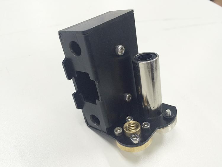
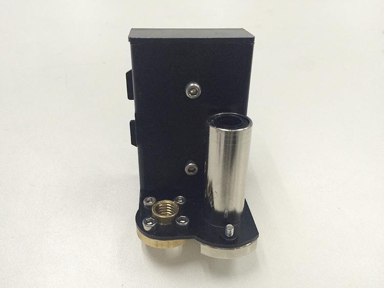
11 Step 3. Push the Y Motor holder tab into the square hole in Rear -Outside Plate and Rear - Inside Plate. You may need to use a little force, but be careful not to break or crack any of the Acrylic pieces. Secure the Y Motor holder with 2 M3x20 mm Screws, 2 M3 Washers and 2 M3 Square Nuts. (*SCS8UU in the picture are just for reference, you are using the PCS8UU linear bearings ) You can watch the video here. 5. Y belt driving wheel Part name Part ID Required number pic Driven wheel No.42 1 holder 9
12 Driven wheel No.43 1 R84zz Ball Bearing No.44 2 M3 x20mm screw No.27 1 M4 x 25mm screw No.35 1 M3 washer No.7 1 M4 washer No.8 1 M4 lock nut No.14 1 wing nut No.15 1 Step1. Thread the M3 x 20 screw and M3 washer through the Driven wheel holder. 10
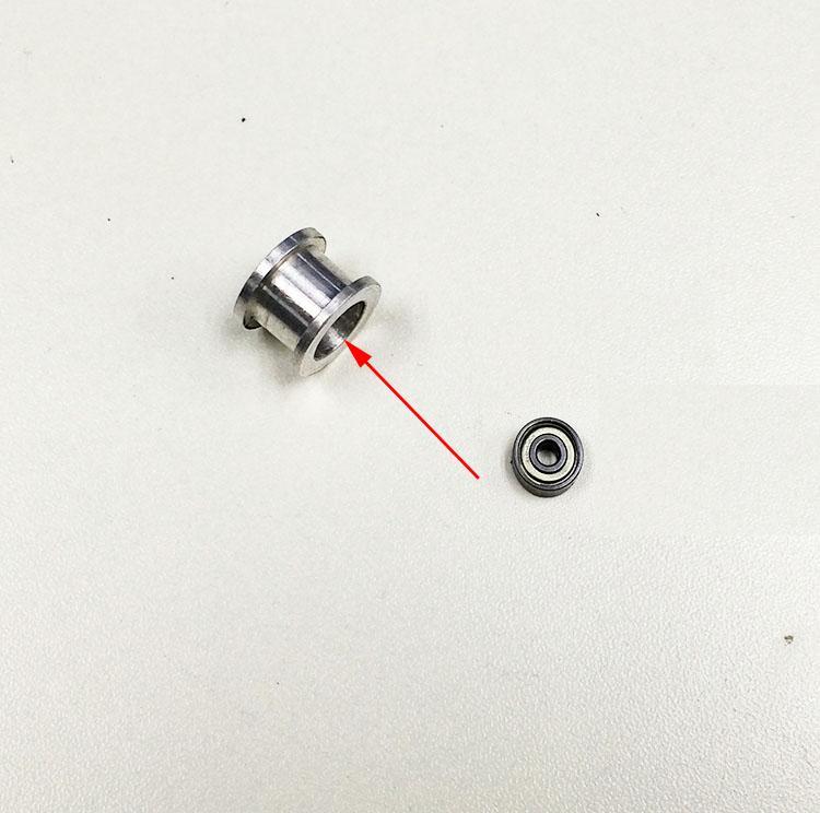
13 Step2. Insert the two MR84zz ball bearings into both ends of the driving wheel. 11
14 Step3.Put the M4 x25 screw and M4 washer through the driving wheel. Lock the other end with a M4 lock nut. You may need a wrench to tighten locking nut. 12

15 *Do not screw it too tight, you should leave enough room for the wheel to turn freely. Step4. Mount the assembled bearing holder onto the front support plates. And screw it with a wing nut. 13


16 (*SCS8UU in the picture are just for reference, you are using the PCS8UU linear bearings ) Look at this picture, the driving wheel and the pulley should be in a straight line. You can refer to the video here. 6. Build the print platform Part name Part ID Required number pic Building platform No.A15 1 support Belt mount No.38 1 M3 x12mm screw No.25 2 M4 x 16mm screw No M3 washer No.7 2 M4 washer No.8 16 Hex Nut No.12A 16 Step1. Mount the belt mount at the middle of the building platform support with 2 M3 x12mm screws and M3 washers. 14


17 Step2. Mount the the building platform support on the 4 PCS8UU linear bearings on the rod with M4x16mm screws and M4 nut. 15

18 (*SCS8UU in the picture are just for reference, you are using the PCS8UU linear bearings ) * Note the direction of the building platform support, you can judge from the direction of the belt mount, whose direction is corresponding to the Y axis. You can refer to the video here. 7. Mount the Y belt Part name Part ID Required number pic Timing belt No.46 1 M3 x8mm screw No.23 2 M3 washer No.7 2 Step1. Punch a M2.5 hole on one end of the belt (the hole can be as the diameter of the M2.5 screw, leave enough margin) Step2. Fix the belt on one side of the belt -mount with a M3 x 8 screw and washer(. 16

19 Step3. Thread the belt around the pulley on the motor and the driving wheel. Step4. Taut the belt to determine the length of the belt, punch another hole and and fix the other end of the belt mount with a M3 x 8 screw and washer. Step5. Cut off the rest of the belt 17

20 (*SCS8UU in the picture are just for reference, you are using the PCS8UU linear bearings ) *Tips: 1. Before you drill your second hole, make sure to pull belt tightly to find the proper placement of hole for a tight belt, if it is too loose, it will hinder the move of the print platform. 2. Loosen the Y idler wing nut when tightening belt onto the Y belt mount in order to make securing the belt to the block easier. Be sure to tighten wing nut fully once done. 3. The belt should be vertical with the Y axis support plate. Watch the video here Right Z motor mount Part name Part ID Required number pic 18
21 M3 x 16mm screw No.26 5 M3 Square nut No.17 5 M3 washer No.7 5 Motor holder No.A5 1 (right) Motor Holder No.A6 2 support Step1. Assemble the 2 A6 and A5 together, screw up with 3 M3 x 16mm screw,m3 washer and M3 Square nut. *Note the direction of the A5,the small round hole is on the right. 19

22 Step2. Fix the assembled motor mount on the right-bottom of A1 with M3 x 16mm screw, M3 washer and M3 Square nut. *Be very careful here, if you can not insert it into the hole you can loose the screw on the motor mount and try again. Watch the video here Left Z motor mount Part name Part ID Required number pic M3 x 16mm screw No.26 5 M3 Square nut No.17 5 M3 washer No.7 5 Motor holder (left) No.A4 1 20


23 Motor Holder No.A6 1 support Motor Holder No.A7 1 support Main frame No.A1 1 Step 1. Insert the A6 and A7 into A5, note the detail:a7 is on the left and A6 is on the right. *Note the direction of the A4,the small round hole is on the left. Step 2. Fix the assembled motor mount on the left-bottom of A1 with M3 x 16mm screw, M3 and square nut. 21

 No.")
24 *Be very careful here, if you can not insert them into the hole you can loose the screw on the motor mount and try again. Watch the video here. 9. Side panel assembly Part name Part ID Required number pic M3 x 16mm screw No.26 6 M3 Square nut No.17 6 M3 washer No.7 6 Side panel(left) No.A2 1 22

25 Side panel(right) No.A3 1 Fix the side panels on A1 with M3 x 16mm screw, M3 Square nut and M3 washer. Watch the video here. If the tab doesn t fit the hole, there must be some manufacturing faulty, please use the file to trim it. 10. Main frame assembly Part name Part ID Required number pic 23
26 M3 x 16mm screw No.26 2 M3 x 20mm screw No M3 hex nut No.12 4 M3 square nut No.17 2 M3 washer No.7 6 Step 1. Put the assembled Y axis into the main frame, put the main frame between the connecting fender and the M10 nut. The Connecting fender is at the front part of the Y axis. Step 2. Connect the side panel to the rear support plate, screw it up with M3 x 16mm screw,m3 washer and M3 square nut. Step 3. Fix the connecting fender to A1 with M3 x 20mm screw, M3 washer and M3 hex nut. 24


27 Watch video here. 11. Fan mount Part name Part ID Required number pic M3 x 25mm screw No M3 hex nut No M3 washer No.7 6 Fan No.51 1 Mount the fan on the BACK of the left side of the A1. Fix it with 4 M3 x 25 mm screw, M3 washer and 4 M3 hex nut. 25

28 Note the direction of the fan, the side with wires is at outside. The fan is for the heat dissipation of the control board. You can see from the video. Watch the video here. 12. Mount the Z endstop Part name Part ID Required number pic M2.5 x 16mm No screw M2.5 hex nut No \ End stop No.54 1 Mount the endstop on the outside of A7 with M2.5 x 16mm screw and M2.5 hex nut 26

29 Watch video here. 13. Mount the Z motors Part name Part ID Required number pic stepper motor No.65 2 M3 x12mm screw No.25 8 M3 washer No.7 6 Step1.Thread the wires of the motor through the holes on the bottom of A1. 27

30 Step2.Screw up the motors on A5 with 4 M3 x 12 screws and M3 washers. Mount the other Z motor on A4 in the same way. For detailed assembly process, please watch here. 28


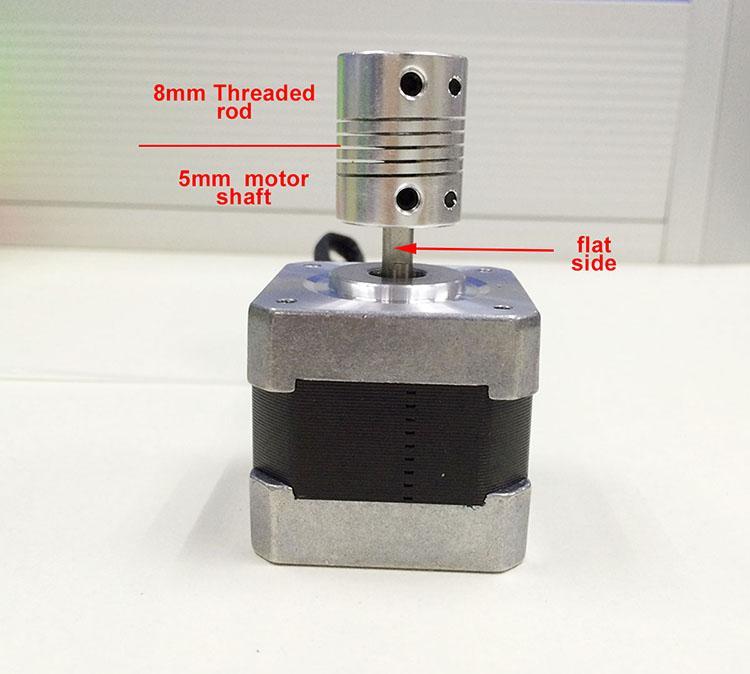
31 14. Mount the couplings Part name Part ID Required number pic Coupling No.48 2 Step 1. Fix the two couplings on the Z motor shaft separately. Please note: 1. The opening of both end, one is 5mm, another is 8mm, connect the 5mm hole to the motor shaft.half and half. Screw it tightly. 2. The screw should be fixed on the cross section (the flat side) of the motor shaft. 29
32 30


33 Repeat the steps for another couplings. Shenzhen GETECH CO.,LTD * the bottom of the coupling is better to be leveled with No. A4. Watch video here. 15. Mount the building platform. Part name Part ID Required number pic Thermometry & No.58 1 Heating wire Heatbed set No.59 1 Building platform No.60 1 wing nut No.15 4 M3x30 mm Hex 4 Counter- No.19 sunk-head screw Spring No.36 4 Step 1.Stack the heatbed and the aluminum plate together with he aluminum plate above, the heat bed below. Step 2.Connect the heatbed and the aluminum plate to the acrylic plate with 4 Hex Counter-sunk-head screw with the spring in between. Step 3. Lock the screw with a wing nut. 31
 For the whole process of")

34 For detailed video tutorial, please watch here. 16. Assemble the left end of the X axis(motor end) For the whole process of assembly of this part, please refer here Mount the Z-axis nut, linear bearing Part name Part ID Required number pic Z-axis nut No.16 1 X-axis motor end No.M1 1 32
35 Linear Bearing No LMH8LUU M3 x 50 screw No.31 1 M3 x 6mm screw No M3 washer No. 7 2 \ Spring No Step1. Mount the Z nut on the X-axis left end from bottom to up, fix with M3 x 6mm screws. Step2. Mount the linear bearing on X-axis motor end from bottom to up. Fix it up with M3 x 6mm screws Mount the endstop trigger. 1. Thread a M3 washer> spring> M3 washer in order to the M3x50mm screw. 2. Thread half of the M3x50mm screw into the screw hole. 33

36 16. 3 mount the X motor. Part name Part ID Required number pic M3 x 6 mm screw No Stepper motor No.65 1 Pulley No.45 1 Step 1. Mount the pulley on the motor shaft. Screw it on the flat side. 34


37 Step 2.Mount the stepper motor on the motor end with 3 M3 x 6 mm screw. 35

38 16.4 Mount the endstop Part name Part ID Required number pic M2.5 x 8 mm No screw End stop No.54 1 Mount the endstop on the top of X-axis motor end with two M2.5 x 8mm screw. 36
39 37
 For the whole process of assembly of this part, please refer to the video here.")

40 17. Assemble the right end of the X axis. (X idler end) For the whole process of assembly of this part, please refer to the video here. Part name Part ID Required number pic Z-axis nut No.16 1 X-axis idle end No.M2 1 Linear Bearing No LMH8LUU M3 x 6mm screw No Step1.Mount the Z axis nut on the bottom of X-axis right end with 4 M3 x 6mm screws. Step2. Mount the linear bearing on X-axis motor end from bottom to up. Fix it up with M3 x 6mm screws. 38
41 39


42 18. Assembly of the extruder carriage Shenzhen GETECH CO.,LTD Part name Part ID Required number pic X Carriage No.M3 1 Bearing Bracket No.M4 4 Extruder holder No.M5 1 Linear Bearing LM8LUU No.40 2 Belt bracket No.47 1 M3x6mm screw No M3x12mm screw No M4x6mm screw No M3 nut No.12 2 Step1.fix the 4 Bearing Brackets on the back of the X Carriage loosely with M3x6mm screws. Insert the linear bearing into the slot and screw the bracket tightly. 40
43 41

44 Please notice the front and back of the plate. The following steps differs from the video, please build based on this manual. Step2.Fix the belt mount on the back of the carriage with 2 M3x 12mm screws and M3 hex nuts. 42
45 Step3. Fix the extruder holder on the front side of the X carriage using M4x6mm screws. 43
46 44

47 19. Assemble the the X&Z axis Part name Part ID Required number pic L320mm threaded No.4 2 rod L340mm smooth No.1 2 rod L470mm smooth No.2 2 rod locking ring No.37 4 Step1. Thread the threaded rod to the nut of both end of X axis. Keep both end of X axis at the same place of the rod, you are advised to measure the 45


48 distance of the both side so that they are at the same level when you put them up. Step2. Plug the threaded rod on the X motor end to the left coupling on the left bottom of the Z axis. Then thread the 340mm smooth rod into the linear bearing. 46

49 Step3. Thread the L470mm smooth rod into the X motor end > thread the extruder carriage> thread the locking ring on the two rods. * Attention please, as a modification on the design, you need to fix the locking ring on the end of the rods, out side the carriages. Step 4. Thread the two X axis smooth rods into the hole of X idler end. Step 5. Plug the vertical threaded rod into the coupling on the right bottom of the Z axis. Then thread the 340mm smooth rod into the linear bearing. Step 6. Add another two locking rings on the end of smooth rod and screw up the 4 locking rings. 47
 20.")
50 Note: the smooth rods and the threaded rod of Z axis is vertical, and the X axis is horizontal,which is very important, or it will hinder the move of the Z axis. Watch video here (the location of the locking ring is different in the video, please assemble referring to this manual) 20. Assemble the Z axis top mount Part name Part ID Required number pic Z top mount No.A8 2 M3 x 16mm screw No.26 6 M3 Square nut No
51 locking ring No.37 2 M3 washer No. 7 6 \ Step1. Put the locking ring on the two smooth rods separately. Step 2. Add the Z top mount (No.A8) to the top of A1. slowly rotate the rods into the holes, or add some lubricants on the rods. Do not force it, or u will break the acrylic piece. Step 3. Screw it up with M3 x 16mm screw and M3 Square nut. Step4. Screw up the locking ring on smooth rods. Watch the video here. 21. X belt driving wheel Part name Part ID Required number pic Driven wheel No.42 1 holder Driven wheel No.43 1 MR84zz Ball No.44 2 Bearing M3 x40mm screw No.30 1 M4 x 25mm screw No.35 1 M3 washer No
52 M4 washer No.8 1 M4 lock nut No.14 1 wing nut No.15 1 Step1. Thread the M3 x 40 screw and M3 washer through the Driven wheel holder. Step2. Insert the two MR84zz ball bearings into both ends of the driving wheel. 50
53 51
54 Step3. Put the M4 x25 screw and M4 washer through the driving wheel. Lock the other end with a M4 lock nut. You may need a wrench to tighten locking nut. 52
55 *Do not screw it too tight, you should leave enough room for the wheel to turn freely. Video 22. Add the belt Part name Part ID Required number pic Timing belt No.46 1 Belt bracket No.47 1 Step1. Insert one end of the belt in the groove. Pay attention to the tooth mesh of the belt and the groove. Step2. Thread another end of the belt through the X motor end around the pulley. Step3. Threaded the belt through the belt driving wheel and put the driving wheel into the X idler end, lock it with a wing nut. 53

56 Step4. Insert another end of the belt into the groove. Cut the spare part. Be sure of the length of the belt. Step5. Taut the belt and tighten the wing nut on the idle end. Tighten the locking rings. 54
 23. Mount the hotend Part name Part ID Required number pic Hotend No.66 1 M4x6mm screw No.")
57 *Note the direction of the bolt on the driving wheel, the side with bolt head should be towards the A1, and the side with pitch facing out, or it will scratch the acrylic plate. Video (the location of the locking ring is different in the video, please assemble referring to this manual) 23. Mount the hotend Part name Part ID Required number pic Hotend No.66 1 M4x6mm screw No M4 washer No.8 1 Mount the hot end on the extruder holder plate from bottom to up with 2 M4x6mm screws and M4 washers. 55


58 Video (Note the extruder holder should be upside down.) 56


59 24. Mount the extruders Shenzhen GETECH CO.,LTD Part name Part ID Required number pic Extruder No.60 2 M4x12mm screw No.33 8 M4 washer No.8 8 Mount the extruders on top of the main frame with M4x12mm screws. Video 57


60 25. Mount the LCD panel Shenzhen GETECH CO.,LTD Part name Part ID Required number pic LCD 2004 No.67 1 Knob No.50 1 Spacer No.49 4 M3 x 12mm screw No.25 4 M3 washer No.7 1 Step 1. Insert the spacer into the 4 holes on the LCD panel from front to back. Step 2.Insert the LCD in the LCD frame on A1, fix it with 4 M3 x 12mm screws and M3 washers. Step 3. Screw up the knob. *Pay attention to the two connectors at the back of the LCD. EXP 1 is for the LCD. EXP 2 is the SD card reader. Do not mix them up. 58


61 Here you can watch the video. 26. Mount the control board. Part name Part ID Required number pic Control board kit No.68 1 Sticker No.56 1 Heat sink No.55 1 Spacer No.49 4 M3 x 12mm screw No.25 4 M3 washer No

62 Step 1. Cut the sticker into small pieces. Shenzhen GETECH CO.,LTD Step2. Past the heat sink onto the chip of the A4988 drivers(on the main board). The sticker is double sided adhesive. Step 3. Insert the spacer into the 4 holes of the board from back to front. Step 4. Mount the board kit on the left side panel with 4 M3 x 12mm screws and M3 washers. Note the direction of the board, the green connectors are downwards to got enough heat dissipation from the fan. Here is the video. 27. Mount the power supply unit(psu ) and the socket. Part name Part ID Required number pic 60


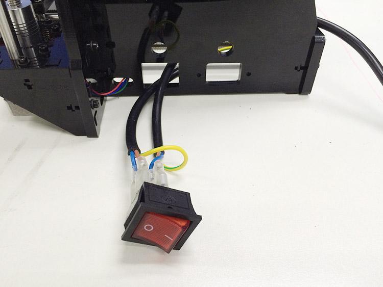
63 Power supply No.61 1 Unit 3D Power Cable No.62 1 M4 x 12mm screw No.33 3 M3 x 16 screw No.18 M3 hex nut No.12 2 M4 washer No.8 1 Power Cable No.63 1 Step 1, take off the wires connected to the socket, before you do, please take a photo of the wire connection, in case you connect them wrongly later. 61
 from outside to inside and")
64 Step 2. Thread the wires that is connected to the red switch through another hole on the bottom of the right side panel( A2) from outside to inside and connect the 3 wires (brown, blue, yellow) to the socket, do not mix them up. Refer to the above picture. Then pull the other wires out. 62
65 63

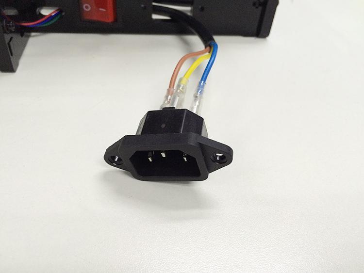
66 Step3. Mount the socket on the bottom of the right side panel( A2) with 2 M3 x 16 Hex Counter- sunk-head screws and M3 hex nut. Step 5. Thread the power cable from inside to outside. Step4. Mount the PSU on the right side panel with 3 M4 x 12mm screws. And M4 washer. Step5. Connect the wires to the PSU. As you can see, there are 7 wires and 9 screws in total. Note the correspondence between the color of wires and the connector. Color of wire Brown Blue Yellow connector L N GND 64

67 Red Black + V COM Video 28. Mount the Y endstop Part name Part ID Required number pic M2.5 x 16mm No screw M2.5 hex nut No \ 65

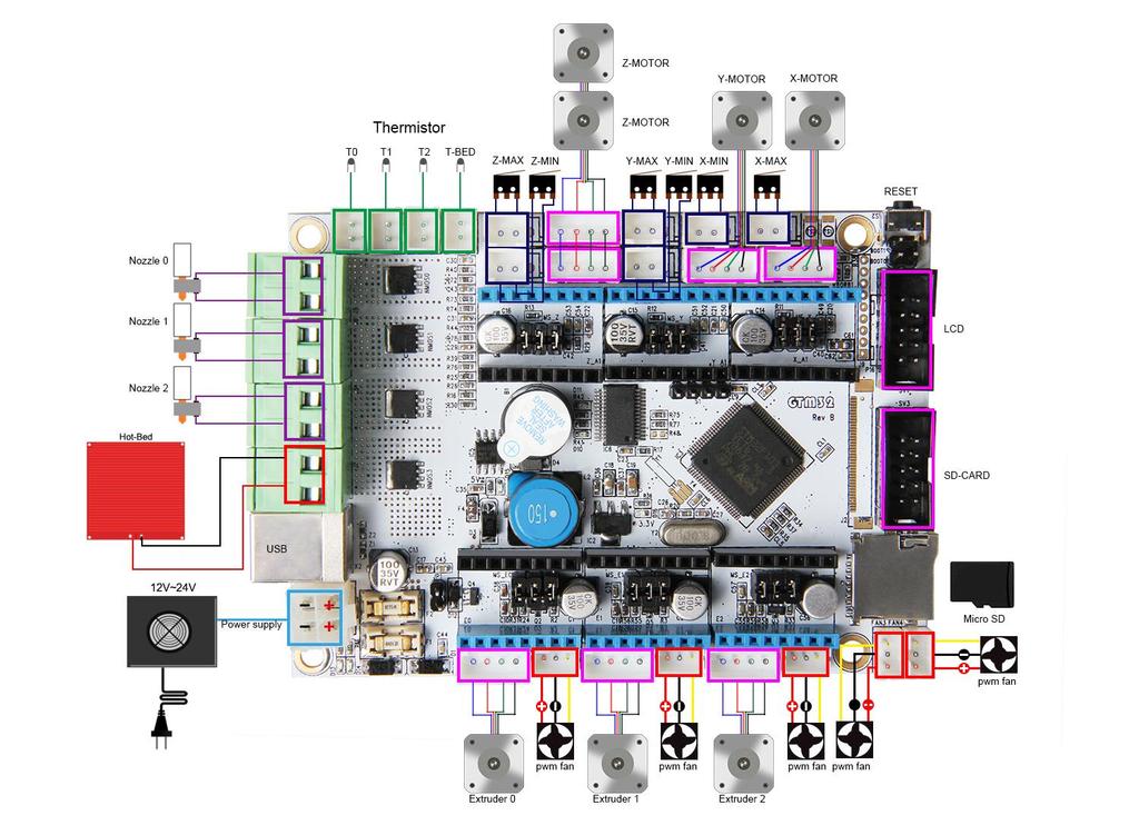
68 End stop No.54 1 Mount the Y axis endstop on A12with M2.5 x 16mm screw and M2.5 hex nut Video 29. Wiring Before you start wiring, please take a look at the wiring schematics. 66

69 Rev A Rev B 67
 Connect wires for X-axis motor.")
70 Note: The only difference between the Rev A and the Rev B here is the USB port, the layout of other connectors are exactly the same. You can refer to both wiring diagrams. You can see original picture here. Step1. Connect wires for motors. 1) Connect wires for X-axis motor. 2) Connect wires for Y-axis motor. 68
71 3) Connect wires for the 2 Z-axis motors. 69

 1 70")
72 4) Connect Extruder motors. Connect extruder 0. 5) Connect extruder 1 70

73 Step2. Connect heating wires. 1) Connect heating wires for heatbed. There are 4 heating wires for the heatbed, 2 black and 2 red, you need to connect the 2 red wires in one screw and the 2 black wires in another. First loos the screws in the green terminal and put the red and black wires into the slot separately, and screw it up. 71

74 2) Connect heating wires for hotend to hotend 0. 72
 Connect wires for thermistor of")
75 Step3. Connect wires for thermistor. 1) Connect wires for thermistor of heatbed 73

 Connect wires for endstop of X-axis at X-Min.")
76 2) Connect wires for thermistor of hotend 0 Shenzhen GETECH CO.,LTD Step4. Connect wires for endstop. 1) Connect wires for endstop of X-axis at X-Min. 2) Connect wires for endstop of Y-axis at Y-Min. 74
 Connect fan for control board at FAN3.")
77 3) Connect wires for endstop of Z-axis at Z-Min. Shenzhen GETECH CO.,LTD Step5. Connect wires for Fan. 1) Connect fan for control board at FAN3. 2) Connect fan for extruder 0 at FAN0. 75
 Connect fan for hotend at FAN4.")

78 3) Connect fan for extruder 1, connect the other to FAN1. 4) Connect fan for hotend at FAN4. Note: for the fan of hotend, you will need the extension wire. Just connect the red and black connectors. 76


79 Step6. Connect wires for LCD panel. There are two cables, one is for LCD encoder, the other is for SD card. EXP1 to LCD EXP2 to SD card BTW, do you see the small screw above the SD card reader, if the text in of the LCD phases in an out or there is only blocks on the screen, you can adjust this screw to recovery it. 77

80 Step7. Connect wires for power input. 78


81 Step8. Connect the wires to the PSU. Shenzhen GETECH CO.,LTD Note the correspondence between the color of wires and the connector. Brown------L Blue N Yellow----GND Red V Black------COM That is all for the wiring of GTM32. Do not forget to stick the heatsink on the chip of each stepper motor driver board. 30. Mount the filament spool. Part name Part ID Required number pic M3 x 16mm screw No.26 6 M3 Square nut No.17 6 M3 washer No.7 6 Spool base plate 1 Spool side pane 2 PVC tube 1 79


82 PVC tube 2 So far, the whole printer is built up, you can tidy up the wires with the zip ties and the coil wire. Before even attempting the first print it is vital that the printer is correctly calibrated. Skipping or rushing this step will result in frustration and failed prints later, so it is important to take the time to make sure the machine is correctly set up. Each machine may have its own calibration procedure and this manual will not attempt to cover all the variations. Instead here is a list of key points that should be addressed. Frame is stable and correctly aligned. Belts are taut. Bed is level in relation to the path of the extruder. Filament rolls freely from the spool, without causing too much tension on the extruder. 80
83 Current for stepper motors is set to the correct level. Firmware settings are correct including: axis movement speeds and acceleration; temperature control; end-stops; motor directions. Extruder is calibrated in the firmware with the correct steps per mm of filament. The point regarding the extruder step rate is vital. Slic3r expects that the machine will accurately produce a set amount of filament when told to do so. Too much will result in blobs and other imperfections in the print. Too little will result in gaps and poor inter-layer adhesion. 81
Building Instructions of Geeetech Prusa I3 M201
 Building Instructions of Geeetech Prusa I3 M201 (Version 11-25-2016) CONTENT Safety Instructions... 1 Preparation... 2 1. Assemble the threaded rods of Y axis... 3 2. Assemble the front and back support
Assembly Instructions of Geeetech Aluminum Prusa I3
 Assembly Instructions of Geeetech Aluminum Prusa I3 CONTENT Safety Instructions... 3 Preparation... 4 1. Unfold the box and check the package... 1 2. Assemble Y axis... 1 3. Build the printing platform...
Assembly Instructions of Geeetech Prusa I3 A pro
 Assembly Instructions of Geeetech Prusa I3 A pro (Version 04-11-2016) CONTENT Safety Instructions... 3 Preparation... 4 1. Unfold the box and check the package... 1 2. Assemble Y axis... 1 3. Build the
Building Instruction of Geeetech Prusa I3 pro W. 3D Printer
 Building Instruction of Geeetech Prusa I3 pro W 3D Printer Version 05-31-2017 Contents Safety Instructions... 2 Preparations... 3 1.Unfold the box and check the package... 4 2 Assemble the rods of a Y
Assemble Manual of Geeetech Acrylic Prusa I3 (8mm)
") Assemble Manual of Geeetech Acrylic Prusa I3 (8mm) Warning: Shenzhen GETECH CO.,LTD. This kit contains tiny parts; please keep them away from kids under 3.. Building and operating 3D printer involves electricity,
Assemble Manual of Geeetech Acrylic Prusa I3 (8mm) Warning: Shenzhen GETECH CO.,LTD. This kit contains tiny parts; please keep them away from kids under 3.. Building and operating 3D printer involves electricity,
Delta Rostock mini G2S Pro 3D Printer
 Delta Rostock mini G2S Pro 3D Printer Copyright Declaration The copyright of this manual belongs to the Shenzhen GETECH CO., LTD. (hereinafter referred to as the "Geeetech"), and all rights reserved. No
Geeetech Prusa I3 M201
 Geeetech Prusa I3 M20 Copyright Declaration The copyright of this manual belongs to the Shenzhen GETECH CO., LTD. (hereinafter referred to as the "Geeetech"), and all rights reserved. No part of this specification
Copyright Declaration
 Geeetech Prusa I3 X Copyright Declaration The copyright of this manual belongs to the Shenzhen GETECH CO., LTD. (hereinafter referred to as the "Geeetech"), and all rights reserved. No part of this specification
Geeetech Prusa I3 M201. Assembly Manual
 Geeetech Prusa I3 M20 Assembly Manual SUPPORT Thanks for choosing Geeetech, we strive to provide a satisfied and pleasant shopping experience for you, but we do understand there may be some questions you
Prusa i3 Printer Assembly Guide
 Prusa i3 Printer Assembly Guide Special thanks to Carlos Sanchez and Miguel Sanchez for the graphics. All graphics captured from their great animation: http://www.carlos-sanchez.com/ Prusa3/ For copyright
TL4076 Top 5 Tips Get to know your TL4076
 TL4076 Top 5 Tips Get to know your TL4076 Thermal Break with Teflon liner (behind fan) Hot End Assembly Fan Heat Block Extruder with toothed gear(brass) and idler (steel) Filament Guide Tube Nozzle Cable
5. Extruder Assembly
 5. Extruder Assembly Guide for the assembly of the Extruder. Written By: Josef Prusa 2018 manual.prusa3d.com/ Page 1 of 24 Step 1 Get the necessary tools 2.5 and 1.5 mm Allen key Needle-nose pliers 2018
Modix Big-60 Assembly Manual Part 2
 Modix Big-60 Assembly Manual Part 2 Version 1.0, October 2017 Menu 1. Motors & End Stop Wiring... 3 2. Controller Wiring Check... 6 3. Extruder Wiring... 7 4. Electronic Box Cover... 9 5. Filament Sensor...
5. E-axis assembly. 5. E-axis assembly. Written By: Jakub Dolezal manual.prusa3d.com/ Page 1 of 40
 5. E-axis assembly Written By: Jakub Dolezal 2018 manual.prusa3d.com/ Page 1 of 40 Step 1 Tools necessary for this chapter Needle-nose pliers for zip tie trimming. 2.5mm Allen key for M3 screws 2mm Allen
3. Extruder Assembly
 3. Extruder Assembly Guide for the assembly of the Extruder. Written By: Josef Prusa 2017 manual.prusa3d.com Page 1 of 22 Step 1 Get the necessary tools 2.5 and 1.5 mm Allen key Needle-nose pliers Step
Upgrade v3 to v3.2. SeeMeCNC Guides. Upgrade v3 to v3.2. Rostock Max v3 Uprgade to v3.2. Written By: SeeMeCNC seemecnc.dozuki.
 SeeMeCNC Guides Upgrade v3 to v3.2 Rostock Max v3 Uprgade to v3.2 Written By: SeeMeCNC 2018 seemecnc.dozuki.com/ Page 1 of 34 INTRODUCTION This guide is intended to Upgrade a Rostock Max v3 to a Rostock
Modix Big-60 Assembly Instructions Part 1
 Modix Big-60 Assembly Instructions Part 1 Version 1.0, October 2017 Menu 1. X Idler Pulley Assembly... 3 2. Connecting X Axis Brackets to Z Profiles... 4 3. Assemble X Rails on X Top Profiles... 6 4. Assemble
8. Electronics assembly (B3/R2 design)
") 8. Electronics assembly (B3/R2 design) Written By: Jakub Dolezal 2018 manual.prusa3d.com/ Page 1 of 31 Step 1 Tools necessary for this chapter Needle-nose pliers for zip tie trimming. 2.5mm Allen key for
8. Electronics assembly (B3/R2 design) Written By: Jakub Dolezal 2018 manual.prusa3d.com/ Page 1 of 31 Step 1 Tools necessary for this chapter Needle-nose pliers for zip tie trimming. 2.5mm Allen key for
Written By: Josef Prusa
 7. PSU & Heatbed assembly PSU and Heatbed guide Written By: Josef Prusa 2017 manual.prusa3d.com/ Page 1 of 17 Step 1 Getting the necessary tools 2 and 2.5 mm allen key Needle-nose pliers Step 2 3D printed
JGAURORA 3D PRINTER MODEL: A5 USER GUIDE
 JGAURORA 3D PRINTER MODEL: A5 USER GUIDE Contents ----3D Printer User Guide 1. Preface... 2 1.1 Introduction...2 1.2 Safety advice... 2 1.3 Filament requirements...2 1.4 Environmental requirements...2
Pi Instruction Manual. Mechanical
 Pi3 2014 Instruction Manual Document No MANUAL WBS Pi3 2014 DIY REV01 Mechanical 3D LabteK Model 1 / 37 Content Page Introduction 2 Printed Parts 3 1, Mechanical 4 1,1 Frame Assembly 6 1,2 Y Axis Assembly
To be the Chief Evangelist CR-10S Pro Printer Guide Book To make Top-quality 3D printer
 To be the Chief Evangelist CR-0S Pro Printer Guide Book To make Top-quality 3D printer This guide book is for standard CR-0S Pro. Please plug the power cord into a three-hole power jack. Detailed instructions
3D PRINTER USER MANUAL
 3D PRINTER USER MANUAL Table of contents page: 1. Introduction 2. Table of contents 3. Basic informations 4. General information 5. Glossary 6. Starter pack s content 7. Technical parameters 8. Device
TeeBox. The Suitcase 3D printer. BY:
 TeeBox The Suitcase 3D printer. BY: Eindhoven The Netherlands Contents Liability... 2 Returns... 2 WARNING... Error! Bookmark not defined. TRICKS AND TIP... 4 PART 1 ---Y AXIS (PRINT BED)... 7 Fasten heatbed
ASSEMBLY MANUAL TINKERINE STUDIO. 3D Printer + Creative Solution
 + ASSEMBLY MANUAL 3D Printer + Creative Solution CONTENTS Safety Instructions Ditto at a Glance Bill of Materials Before You Start Z-Platform Ditto Frame pt.1 Ditto Frame pt.2 Gantry pt.1 Gantry pt.2 Gantry
Maker's Tool Works. Written By: Micro. Wiring methods used by MTW Printers using the Rambo Electronics. Wiring Rambo Electronics & Power Supply
 Maker's Tool Works Wiring Rambo Electronics & Power Supply Wiring methods used by MTW Printers using the Rambo Electronics. Written By: Micro 2017 mtw.dozuki.com Page 1 of 10 TOOLS: Screw Drivers (1) Wire
M2 Wiring. Table of Contents
 M2 Wiring Table of Contents M2 Wiring Harness... 2 RAMBo... 3 Wire Harness 1... 4 Wire Harness 2... 5 Wire Harness 3... 6 Wire Harness 4... 7 Wire Harness 5... 8 Connecting Wiring Harness to M2 Printer...
6. Pre-print checks. 3D Touch
 Page 1 1. 6. Pre-print checks........................................................................................... 1.1 a. Clearing the print bed..................................................................................
Quick Starter Manual for PrusaM201
 Quick Starter Manual for PrusaM201 Copyright Declaration The copyright of this specification belongs to the Shenzhen GETECH CO., LTD. (hereinafter referred to as the "Geeetech"), and all rights reserved.
WANHAO Duplicator i3. User Manual V1.2. Wanhao USA
 WANHAO Duplicator i3 User Manual V1.2 Wanhao USA 2015 www.wanhaousa.com Safety WARNING: The components on the Duplicator i3 generate high temperatures and move extremely fast. Reaching inside of the Duplicator
CONTENTS. Safety Instructions. Litto at a Glance. Bill of Materials. Before You Start. Z-Platform. Litto Frame pt.1. Litto Frame pt.2. Gantry pt.
 ASSEMBLY MANUAL CONTENTS Safety Instructions Litto at a Glance Bill of Materials Before You Start Z-Platform Litto Frame pt.1 Litto Frame pt.2 Gantry pt.1 Gantry pt.2 Gantry pt.3 Carriage Electronics /
Electronics. Electronics docs.imade3d.com/ Page 1 of 15
 Electronics 2018 docs.imade3d.com/ Page 1 of 15 Step 1 Wire Comb 4" zip ties Wire comb Step 2 Align the wire comb with the corresponding annotations (ie. filament fan, heat block, etc.), and secure it
K Wiring and Electronics
 HKBay.com K Wiring and Electronics Written By: HKBay 2017 hkbay.dozuki.com Page 1 of 12 TOOLS: Hex key; ball ended, long arm, 2.5mm (1) PARTS: Arduino Mega (blue) (1) RAMPS board (red) (1) glass tabs (3)
3. X-axis assembly. 3. X-axis assembly. X axis guide. Written By: Josef Prusa manual.prusa3d.com/ Page 1 of 14
 3. X-axis assembly X axis guide Written By: Josef Prusa 2017 manual.prusa3d.com/ Page 1 of 14 Step 1 Getting the necessary tools 1.5mm & 2.5mm Allen key Needle-nose pliers Step 2 3D printed parts X-carriage
SeeMeCNC Guides. Orion Delta HE280 Hotend Upgrade. This How-to Guide will walk you through the steps of upgrading to the HE280 Hotend
 SeeMeCNC Guides Orion Delta HE280 Hotend Upgrade This How-to Guide will walk you through the steps of upgrading to the HE280 Hotend Written By: JJ Johnson 2017 seemecnc.dozuki.com Page 1 of 18 INTRODUCTION
2. Multiplexer assembly
 2. Multiplexer assembly Written By: Jakub Dolezal 2017 manual.prusa3d.com/ Page 1 of 15 Step 1 Parts identification Y-splitter (new version) - QSM fittings and steel tubes are assembled in the factory.
Documentation version 1.42 ASSEMBLY INSTRUCTIONS REV 1.1
 Documentation version 1.42 ASSEMBLY INSTRUCTIONS REV 1.1 / 2 INTRODUCTION / 3 INTRODUCTION Target : Prupose a visual guide of the differents steps to build and use a µdelta printer Designers : Hugo Flye
Installation Instruction of CTC DIY 3D Printer
 Installation Instruction of CTC DIY 3D Printer Focus on high-end science and technology,focus on 3D printing Zhuhai CTC Electronics Co.,Ltd. www.ctcprinter.com 1 Introduction This DIY 3D printer can be
Documentation version ASSEMBLY INSTRUCTIONS
 Documentation version 1.6.30 ASSEMBLY INSTRUCTIONS / 2 INTRODUCTION / 3 INTRODUCTION Target : Propose a visual assembly instruction guide of the MicroDelta Rework. Designers of the MicroDelta Rework :
Important notice Upper supports for Z axis Pulley Corner for Y axis Right X axis and left X axis Chain coupling for left X axis
 Warranty and FAQ G004260 Important notice You can personalise your Prusa i3 HEPHESTOS and update it with the latest innovations that appear in the community. However, it is important that you understand
Documentation version ASSEMBLY INSTRUCTIONS
 Documentation version 1.1.0 ASSEMBLY INSTRUCTIONS / 2 INTRODUCTION / 3 INTRODUCTION Target : Provide a visual guide of the various steps required to assemble the «i3 Metal Motion» 3D printer. Designers
Witbox 2. Quick start guide
 Witbox 2 Quick start guide Welcome. Thank you for choosing us. This manual will help you to use your new 3D printer correctly. Welcome to the world of Witbox 2. How do I use this manual? To make sure that
Introduction to 3D Printing
 TAKE HOME LABS OKLAHOMA STATE UNIVERSITY Introduction to 3D Printing by Sean Hendrix 1 OBJECTIVE The objective of this experiment is to introduce you to 3D printing, by having you print some simple parts
Bondtech for Prusa i3
 Bondtech for Prusa i3 Assembly and installation manual This work is licensed under a GNU General Public License v3.0 Table of Contents Acknowledgements 1 Introduction 1 Compatibility 2 What s in the box?
Please read the safety instructions carefully before get started.
 Safety Instructions Please read the safety instructions carefully before get started. ANYCUBIC 3D printer generates high temperature. Do not reach inside of the printer during operation. Allow time for
3D PRINTER. Pack 09. Anything you can imagine, you can make! 3D technology is now available for you at home! BUILD YOUR OWN
 BUILD YOUR OWN Pack 09 Anything you can imagine, you can make! 3D PRINTER Compatible with Windows 7 & 8 Mac OS X 3D technology is now available for you at home! www.model-space.com BUILD YOUR OWN 3D PRINTER
FlexJet - Flex Cable Replacement
 P/N: 109515R0 14140 NE 200th St. Woodinville, WA. 98072 PH: (425) 398-8282 FX: (425) 398-8383 FlexJet - Flex Cable Replacement Notices: Warning! Ensure that all AC power cables are removed from the printer
How this (and most) 3D Printers work. Forward
 3D Printers work. Forward") Build Manual Contents Contents Contents 2 Forward 4 How this (and most) 3D Printers work. 5 3D Printing Workflow 6 Space to work 7 Tools / Parts Required 7 Build Time 8 How To Use This Manual 8 Acrylic
Build Manual Contents Contents Contents 2 Forward 4 How this (and most) 3D Printers work. 5 3D Printing Workflow 6 Space to work 7 Tools / Parts Required 7 Build Time 8 How To Use This Manual 8 Acrylic
PORSCHE V r Valve Timing Instructions. Copyright 2009 Written by Mike Frye Edited my Adam G.
 PORSCHE 928 32V r Valve Timing Instructions Copyright 2009 Written by Mike Frye Edited my Adam G. Sections: Overview.3 Disclaimer/warnings/things to watch for 4 Terms and naming conventions used in this
Automatic Roof Hatch Opener
 Automatic Roof Hatch Opener Installation Guide REQUIRED TOOLS (These tools are required to complete the installation) Cordless Drill 1/8 1/4 Drill Bits 1/8 Pin Punch #2 Philips Bit Rachet Sharpie Hammer
Assembly Manual FELIX One
 Assembly Manual FELIX One Version 1.0 2018 www.felixprinters.com support@felixprinters.com Zeemanlaan 15 3401 MV IJsselstein The Netherlands Introduction Table of Content Dear Customer, Thank you for choosing
Desktop 5.5 Z Axis Retrofit
 Page 1 Kit parts Desktop 5.5 Z Axis Retrofit Carriage plate with stop bolt and Z proximity switch installed Zip ties Spare bolts Spindle mounting plate with stop bolt, spring mount, and rail Z proximity
Maintenance Manual. Hephestos
 Hephestos 2016 Mundo Reader SL. All rights reserved. The reproduction, copying, distribution, publication or modification of this material is strictly prohibited unless carried out with the express prior
3D TOUCH. Extruder upgrade. Document version 1.0
 3D TOUCH Extruder upgrade Document version 1.0 1 Summary This manual is for the installation of an additional extruder into the 3D Touch. The procedure is the same for both 1 2 head, and 2 3 head upgrades.
5. Extruder. 5. Extruder. Extruder guide. Written By: Dozuki System manual.prusa3d.com Page 1 of 16
 5. Extruder Extruder guide Written By: Dozuki System 2017 manual.prusa3d.com Page 1 of 16 Step 1 Get the necessary tools 2.5, 2 and 1.5 mm hex spanner Needle-nose pliers Step 2 3D printed parts Extruder
Building Instructions Upside Variable Pitch Prop System
 Building Instructions Upside Variable Pitch Prop System it s tim o e t fly! Thank you for buying our revolutionary UPSIDEDOWN VP-Prop System! Experience a new dimension in 3D performance. Assembly and
NWA3D A5 User Manual
 1. NWA3D A5 3D Printer Part Diagrams 2. Assembling the Spool Holder 3. Leveling the Build Plate 4. Loading and Unloading Filament 5. Operation: The Four Steps in 3D Printing 6. Troubleshooting 7. Additional
ATS-9600/9700 TABBER/LABELER
 ATS-9600/9700 TABBER/LABELER OPERATOR'S MANUAL SAFETY PRECAUTIONS THIS EQUIPMENT PRESENTS NO PROBLEM WHEN USED PROPERLY. OBSERVE SAFETY RULES WHEN OPERATING THE TABBER/LABELER. READ THIS MANUAL CAREFULLY
Cold Air Intake Installation Instructions
 BAVARIAN AUTOSPORT Cold Air Intake Installation Instructions PARTS LIST: PF BMWE36-4 PROCEDURE: 1. Using a flat-head screwdriver, loosen the hose clamp between the AFM and rubber boot leading to engine
UM3 Spare Parts Ultimaker 3 Spare-Parts Version /06/18
 Ultimaker 3 Spare-Parts Version 1.2 13/06/18 Housing 1156 Z-Shaft Cap Bottom 1901 Controler Electronics Cover 1902 Main Board Electronics Cover 1903 Cable Cover 1904 Wifi Cover 1905 Print Table Back Cover
3D PRINTER. Pack 10. Anything you can imagine, you can make! 3D technology is now available for you at home! BUILD YOUR OWN
 BUILD YOUR OWN Pack 10 Anything you can imagine, you can make! 3D PRINTER Compatible with Windows 7 & 8 Mac OS X 3D technology is now available for you at home! BUILD YOUR OWN 3D PRINTER CONTENTS PACK
The HMC Heavy Metal Chassis Construction Guide using Timing Pulleys and Belts
 The HMC Heavy Metal Chassis Construction Guide using Timing Pulleys and Belts The Heavy Metal Chassis is constructed using two identical drive modules. Power can be transmitted from the motors to the wheels
Assembly instructions. Veranda sunblind VZ510. art.nr
 Assembly instructions Veranda sunblind VZ510 art.nr. 27807 A. Introduction: Assembly instructions Veranda sunblind VZ510 This assembly guide is available from 15-11-00 and is directed to qualified assemblers.
CALIFORNIA TRIMMER MOWER MAINTENANCE MANUAL
 CALIFORNIA TRIMMER MOWER MAINTENANCE MANUAL 2 Table of Contents Section 1: General Information Page Handle Assembly Instructions 4 Maintenance All Models 6 Oil Change Procedures All Models 9 Height Adjustment
Audi A8 ( ) MMI swivelling unit repair manual
 MMI swivelling unit repair manual") Audi A8 (2003-2007) MMI swivelling unit repair manual Tools which you will need: two pcs screwdriver (any kind, for vent removing ) (you can cover the metal part with any tape to prevent making scratches
Audi A8 (2003-2007) MMI swivelling unit repair manual Tools which you will need: two pcs screwdriver (any kind, for vent removing ) (you can cover the metal part with any tape to prevent making scratches
Air Oil Separator for WRX
 Air Oil Separator for 2015+ WRX 2018-06-05 Thank you for purchasing this PERRIN product for your car! Installation of this product should only be performed by persons experienced with installation of aftermarket
C15C C15C. Page 1 of 20
 2 x Lid Front Hinge 1135 8 x M8 Bolt 8 x M8 Washer (3mm Thick) 4 x M6 Large washers 4 x M6 Spring washers 4 x M6 x 40mm Bolts 6 x M6 20mm Bolts 6 x M6 Washers 20 x Screws 2 x Lid mount gas strut bracket
Cold Air Intake Installation Instructions
 BAVARIAN AUTOSPORT Cold Air Intake Installation Instructions Page 1/5 3.06 INS264 NOTE: The vehicle shown for this installation is equipped with ASC+T. If your vehicle dos not have this feature, installation
OLYMPIAN MODEL 740 Operation and Service Manual
 OLYMPIAN MODEL 740 Operation and Service Manual P/N 133911-102 FCI MANUAL P/N 133865-001 Data herein has been verified and validated and believed adequate for the intended use. If the machine or procedures
INSTALLATION, MAINTENANCE, & SAFETY INSTRUCTIONS
 Tarpaulin Systems Flip -N- Go / Quick Mount Flip -N- Go System INSTALLATION, MAINTENANCE, & SAFETY INSTRUCTIONS (800) CRAMARO (800) 272-6276 Plants In: Delaware, Florida, Massachusetts, Nevada, Ohio Install
RS4000 Setup. Before you install the RS4000 system, check to ensure that nothing was damaged or lost during shipping.
 RS4000 Setup Before you install the RS4000 system, check to ensure that nothing was damaged or lost during shipping. If anything is damaged or missing, contact your salesman immediately. Mount Components
Amateur Radio Station WFØGM Repairing a Yaesu G-1000DXA Rotor
 WFØGM Home http://wf0gm.fpage.com/index.htm Amateur Radio Station WFØGM Repairing a Yaesu G-1000DXA Rotor (Part 1 of 2) The following is my experience with a faulty Yaesu G-1000DXA Rotor, and how I repaired
The H-MAC Heavy Metal Articulating Chassis Construction Guide
 The H-MAC Heavy Metal Articulating Chassis Construction Guide The Heavy Metal Chassis is constructed with two identical drive modules built using 10 mechanical sub-assemblies. The drive modules are integrated
Fast Master Products, Inc. P.O. Box 654, Katy Texas Tel: (281) Fax: (281)
 Fax: (281)") Fast Master Products, Inc. P.O. Box 654, Katy Texas 77492-0654 Tel: (281) 391-6750 Fax: (281) 391-6760 Email: info@cruiserlift.com Easy installation and removal from the pick-up bed. Compatible with all
Fast Master Products, Inc. P.O. Box 654, Katy Texas 77492-0654 Tel: (281) 391-6750 Fax: (281) 391-6760 Email: info@cruiserlift.com Easy installation and removal from the pick-up bed. Compatible with all
FlexJet Carriage Circuit Board (PCB) Replacement
 Replacement") P/N: 111484 R0 14140 NE 200th St. Woodinville, WA. 98072 PH: (425) 398-8282 FX: (425) 398-8383 ioline.com FlexJet Carriage Circuit Board (PCB) Replacement Notices: Warning! Ensure that all AC power cables
P/N: 111484 R0 14140 NE 200th St. Woodinville, WA. 98072 PH: (425) 398-8282 FX: (425) 398-8383 ioline.com FlexJet Carriage Circuit Board (PCB) Replacement Notices: Warning! Ensure that all AC power cables
Fitting Instructions For The TDV6 EGR Blanking Kit To A 2006 Model Discovery 3 TDV6 GHSE
 Part Number DA1112 Fitting Instructions For The TDV6 EGR Blanking Kit To A 2006 Model Discovery 3 TDV6 GHSE You do this modification at your own risk. Britpart won t be held responsible for what is written
RockyHydro. System Assembly Info Packet
 RockyHydro System Assembly Info Packet RockyHydro sells a wide degree of micro-hydro components for various kits. Our customers enjoy the benefit of being able to carefully match a turbine and generator
INSTALLATION AND OPERATION INSTRUCTIONS
 INSTALLATION AND OPERATION INSTRUCTIONS TOOLS NEEDED FOR INSTALLATION: 3/6 metal drill bit /2 metal drill bit Drill Wood block () 3/4 wrench () 9/6 wrench Measuring tape Pencil or scratch awl Center punch
ATS-9600/9700 TABBER/LABELER
 ATS-9600/9700 TABBER/LABELER INSTALLATION AND OPERATING INSTRUCTIONS SAFETY PRECAUTIONS THIS EQUIPMENT PRESENTS NO PROBLEM WHEN USED PROPERLY. HOWEVER, CERTAIN SAFETY RULES SHOULD BE OBSERVED WHEN OPERATING
GENUINE PARTS INSTALLATION INSTRUCTIONS
 GENUINE PARTS INSTALLATION INSTRUCTIONS 1. 2. 3. 4. DESCRIPTION: Accent light Kit APPLICATION: Infiniti JX (2013) PART NUMBER: 999F3 YY000 - Universal Accent Lighting Kit. KIT CONTENTS: Item QTY Description
Mustang Shaker
 2005-2009 Mustang Shaker CDC #110050 ( 05/ 06) or 0711-7000-01 ( 07/ 09) Component Check List: Quantity/Description Part # CDC Installer 1 - Engine Cover Assembly 114050 1 - Aluminum Shaker Scoop 183020
INSTALLATION INSTRUCTIONS HD BUMPER AND WINCH MOUNTING KIT Part Number: 74777, Application: 08-NEWER FORD SUPER DUTY WARNING
 INSTALLATION INSTRUCTIONS HD BUMPER AND WINCH MOUNTING KIT Part Number: 74777, 76250 Application: 08-NEWER FORD SUPER DUTY Your safety, and the safety of others, is very important. To help you make informed
If you have any difficulties at all, please give us a call. Thank you and enjoy your MetalCloak Products!
 PRODUCT: TJ/LJ 3.5 Dual Rate Lift RockSport Edition READ INSTRUCTIONS IN FULL BEFORE INSTALLATION. QUESTIONS? CALL 916-631-8071 M-F 7:00 AM 5:00 PM PST The MetalCloak experience includes the ease of installation
SERIES A & AA ROLLER DOORS INSTALLATION GUIDE
 SERIES A & AA ROLLER DOORS INSTALLATION GUIDE THESE INSTRUCTIONS ARE PROVIDED FOR USE BY EXPERIENCED INSTALLERS OF GARAGE DOORS BY UNDER-TAKING THE INSTALLATION OF THIS DOOR, THE INSTALLER UNDERSTANDS
LoD Offroad. Jeep JK Door Linked Rear Bumper with Tire Carrier Installation Instructions
 LoD Offroad Jeep JK Door Linked Rear Bumper with Tire Carrier Installation Instructions Please read through the instructions before beginning any part of the installation process. Packaging List: 1-Rear
Assembly Manual FELIX Tec 4
 Assembly Manual FELIX Tec 4 Version 5.2 2018 www.felixprinters.com support@felixprinters.com Zeemanlaan 15 401 MV IJsselstein The Netherlands Introduction Table of Content Dear Customer, Thank you for
HIGH FLOW COLD AIR INTAKE SYSTEM INSTALLATION INSTRUCTIONS D , D A
 HIGH FLOW COLD AIR INTAKE SYSTEM INSTALLATION INSTRUCTIONS D760-0320, D760-0320A 1992-95 325i, is 1995 M3 (3.0L) Parts List: 1 Intake Tube 1 Silicone Hose 1 Air Flow Meter Bracket 1 Hose Clamp (#36z) 1
GENUINE PARTS INSTALLATION INSTRUCTIONS
 GENUINE PARTS INSTALLATION INSTRUCTIONS 1. 2. 3. DESCRIPTION: APPLICATION: PART NUMBER: Accent light Kit Cube (MY2013+) 999F3 AW000 - Universal Accent Lighting Kit. 4. KIT CONTENTS: Item QTY Description
INSTALLATION INSTRUCTIONS
 2007-Current Jeep Wrangler 360º System for Factory Display Radios (Kit # AVMS-3701) Please read thoroughly before starting installation and check that kit contents are complete. Items Included in the Kit:
INSTALLATION INSTRUCTIONS
 2007-Current Jeep Wrangler 360º System for Factory Display Radios (Kit # AVMS-3701v2) Please read thoroughly before starting installation and check that kit contents are complete. Items Included in the
PORSCHE 928. PKT Installation 1.6. No air pump version. Air pump version
 PORSCHE 928 PKT Installation No air pump version Air pump version 1.6 Tools Torque wrench 10mm socket 12mm socket 13mm socket 5mm allen socket 6mm allen socket 8mm allen key Caliper Supplies Blue Loctite
MODEL 2604 WARNING <THESE INSTRUCTIONS MUST BE GIVEN TO THE END USER> Custom 5th Wheel Hitch Mounting Rail Installation Instructions
 B&W Trailer Hitches 1216 Hawaii Rd / PO Box 186 Humboldt, KS 66748 P:620.473.3664 F:620.869.9031 Custom 5th Wheel Hitch Mounting Rail Installation Instructions
Trifecta 800 3D Printer. User s Guide
 Trifecta 800 3D Printer User s Guide Table of Contents 3 SAFETY WARNINGS 4 WARRANTY 5 SPECIFICATIONS 6 PRINTER OVERVIEW 7 UNBOXING 9 10 11 12 13 14 15 17 18 20 22 25 26 FILAMENT INSTALLATION PRINT BED
The HMC Heavy Metal Chassis Construction Guide
 The HMC Heavy Metal Chassis Construction Guide The Heavy Metal Chassis is constructed using two identical drive modules. The drive modules are constructed using 4 mechanical sub-assemblies. The drive modules
NWA3D A31 User Manual
 1. 3D Printer Parts Diagram 2. Assembly 3. Fine-Tuning 4. Leveling the Build Plate 5. Loading and Unloading Filament 6. Operation: The Four Steps in 3D Printing 7. Troubleshooting Version 2.0 8. Additional
, Ford F-250/F-350, Single Rear Wheel Rear Mount Bracket with Mud Flap Mounting Diagram & Instructions GB759842
 2017-2019, Ford F-250/F-350, Single Rear Wheel Rear Mount Bracket with Mud Flap Mounting Diagram & Instructions GB759842 IMPORTANT: The manufacturer is not responsible for negligent use of vehicle with
Assembly & Installation Guide Makerbot Rep2X and clones
 Assembly & Installation Guide Makerbot Rep2X and clones The Bondtech extruder upgrade kit for Makerbot and clones uses high-quality industrial pneumatic push-fit fittings for attaching the bowden tube.
Kit1 300B Edition. Single Ended Triode 8 Watt. Construction Manual & User Guide Volume One
 Kit1 300B 2014 Edition Single Ended Triode 8 Watt Construction Manual & User Guide Volume One Contents Section 1: Receiving your kit...2 Section 2: The Mechanical section Preparation... 3 Tang Strips...
I. Before starting installation
 5. Park the vehicle on a clean, dry, flat, level surface and block the tires so the vehicle cannot roll in either direction. A. Disconnect battery cables 1. Disconnect the negative cable first, then the
Assembly Manual. 1/10th Formula 1 Car
 Assembly Manual 1/10th Formula 1 Car Center Pivot Bag 1 3374 - Center Pivot Socket 40194 - Hard Anodized Alum Pivot ball 3254-2-56 *Note - Sometimes it is helpful to slightly over-tighten the top clamp