Pi Instruction Manual. Mechanical
|
|
|
- Amanda Carroll
- 6 years ago
- Views:
Transcription
1 Pi Instruction Manual Document No MANUAL WBS Pi DIY REV01 Mechanical 3D LabteK Model 1 / 37
2 Content Page Introduction 2 Printed Parts 3 1, Mechanical 4 1,1 Frame Assembly 6 1,2 Y Axis Assembly 9 1,3 Z Axis Assembly 19 1,4 X Axis Assembly 24 1,5 Extruder Assembly 31 INTRODUCTION
3 This manual is intended to be used for assembly the mechanical parts of your Prusa i Although many information about this printer model are available on line, we would like to warn about the information you are going to collect. Unfortunately there are so many variation around the original project that not every solution available on internet is suitable for all the variation. In case of doubt you can contact us at the following mail Printed Parts


4 Y corner x4 Y motor x 1 Y Idler x 1 Y endstop holder x 1 Y belt tensioner x 1 Y 624 bearing guide x 2 Y LM8UU Holder x 3 X carriage adapter x 1 Z bottom motor x 2 Z top x 2 Z end stop holder x 1 X end motor x 1 X end Idler x 1 X carriage x 1 X endstop holder x 1


5 X 624 bearing guide x 2 Gerg Extruder V3 x 1 Big Gear x 1 small gear x1 Idler bearing x 1 X Belt Tensioner
6 FRAME ASSEMBLY 1.1 Skip the Frame Steps if you have a standard single plate Aluminum frame. STEP 1 Install the reinforcement with the electronic controller fixing holes on the left side of the frame. Refer to the image balloon to identify the component used in the above BOM
7 Install the second reinforcement on the right side of the frame. Mechanical
8 Install the Spacer in the holes that best fit your Electronics Controller Mechanical
9 Y Axis ASSEMBLY 1.2 Please Note that having the single plate frame the position 4of the BOM will have the same dimension of the position 5
10 Install the Y Belt Holder under the Y Carriage, place in position also the belt trap (18 19) Mechanical
11 Install the LM8UU using the Y Bushing (7) on the bottom side of the Y Carriage (12) Mechanical
12 Install The M10 Threaded Rod (2) into the Y Corner (1) and set also the required M10 Nut almost in the center of the Rod They will be used to Fix the Y Axis to the frame Repeat this Operation for both side of the Y Carriage, do not Fix the smooth rod on top using the cable ties yet. Mechanical
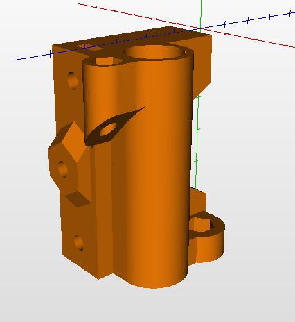
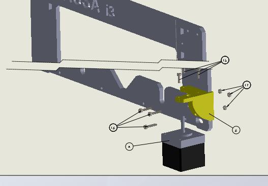
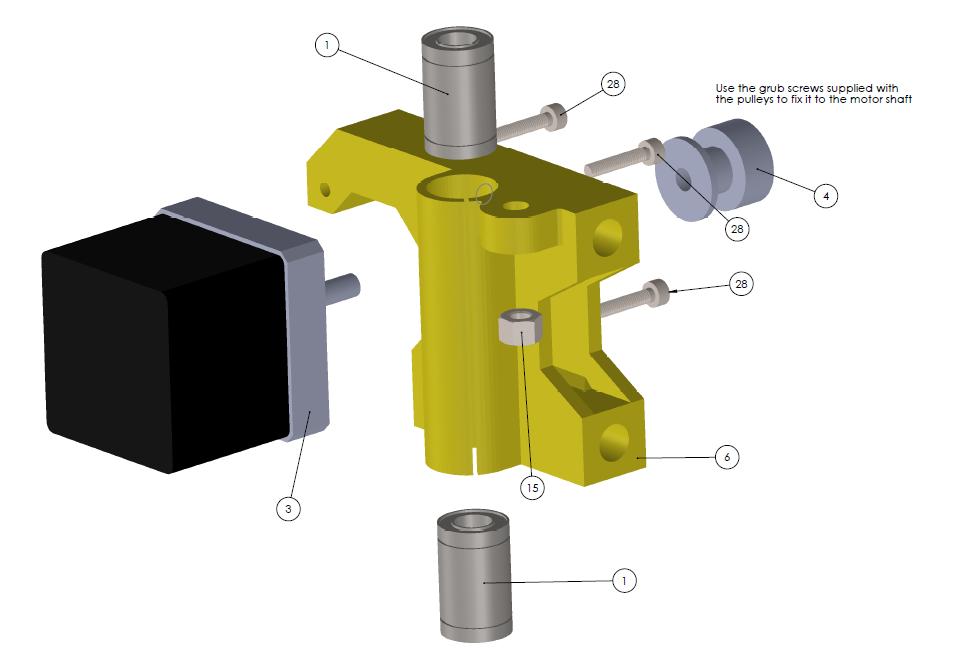
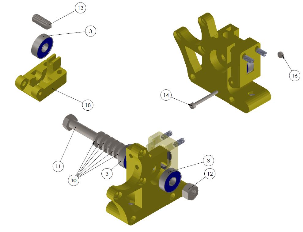
13 Install the Belt Pulley (12) On the Nema 17 Motor (11) using the grub screw (38) supplied with the pulley. Install the Motor bracket (19) on the Nema 17 Motor Mechanical
14 Install the M8 Threaded rod (4 5) on the motor bracket. Do not tight the M8 Nuts of the bars, Mechanical
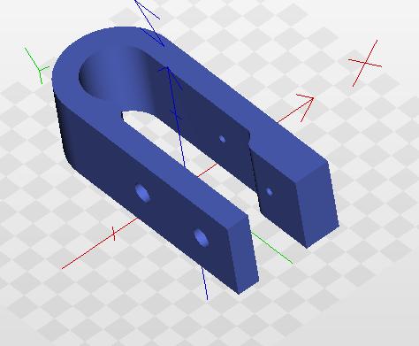
15 On the fron side of the machine install the remaining M8 Threaded rod (5) on the Y endstop holder (16) and the Y Belt idler(9) the Limits switch (18) can be installed now or after the completion of the Y axis. Mechanical
16 Install the previous step on the Y Corner but do not tight the nuts as all the parts must be aligned. Mechanical
17 Install the motor side on the Y corner leave the M8 nuts loose until the Y carriage it is not in position 17 / 37
18 Slide the Y carriage into the Y smooth Rod (3) and place the smooth rods in the Y corners both side. Tight all the M8 Nuts on the right side. Slide the Y Carriage in front and set the M8 Nuts of the Front left side, Slide the Y carriage on the rear and set the M8 Nuts on the rear left side. The carriage must run smooth from front to rear, if you note some extra force needed to complete the stroke it means that the M8 Nuts should be adjusted to keep the same distance like in the other side. Dismante the belt trap on the Y belt holder (motor side) and fix the belt inside, put back in position and let the belt reach the motor pulley, this is the time to center the pulley with the belt holder and tight the M8 Nuts of the motor bracket. Pass the belt below the Y carriage up to the Y idler, and back to the Y carriage, release the tensioner of the idler, dismantle the belt trap from the belt holder and fix the belt inside. Before to tight the belt be sure that the Y IDler is centered with the Bel holder. tight the belt and set the Y Axis apart for the moment. Please note that in the BOM there are 4 M3x10 bolts (37) that will be used to fix the heat bed. 18 / 37

19 ZAxis ASSEMBLY / 37

20 Install the Left Z bottom (11) on the frame Install the Motor on the Z bottom repeat for the right side 20 / 37
21 21 / 37

22 Install the Z axis Coupler (17) on the M5 threaded rod (18) Set the grub screws on the Z axis coupler body but do not tight. 22 / 37


23 Install the Z top on the frame on the left side but do not tight the bolt needed to trap the Z smooth rod. Repeat for the right side 23 / 37
24 Install the M5 Threaded rod on the motor but do not tight the motor side grub sceew yet. 24 / 37

25 X AXIS ASSEMBLY / 37
26 26 / 37
27 27 / 37
28 28 / 37
29 29 / 37
30 30 / 37
31 31 / 37
32 EXTRUDER ASSEMBLY / 37
33 33 / 37

34 CUT THE SPRING (19) at the proper length 34 / 37
35 35 / 37
36 36 / 37
37 37 / 37
Prusa i3 Printer Assembly Guide
 Prusa i3 Printer Assembly Guide Special thanks to Carlos Sanchez and Miguel Sanchez for the graphics. All graphics captured from their great animation: http://www.carlos-sanchez.com/ Prusa3/ For copyright
3. X-axis assembly. 3. X-axis assembly. X axis guide. Written By: Josef Prusa manual.prusa3d.com/ Page 1 of 14
 3. X-axis assembly X axis guide Written By: Josef Prusa 2017 manual.prusa3d.com/ Page 1 of 14 Step 1 Getting the necessary tools 1.5mm & 2.5mm Allen key Needle-nose pliers Step 2 3D printed parts X-carriage
Assembly Instructions of Geeetech Prusa I3 A pro
 Assembly Instructions of Geeetech Prusa I3 A pro (Version 04-11-2016) CONTENT Safety Instructions... 3 Preparation... 4 1. Unfold the box and check the package... 1 2. Assemble Y axis... 1 3. Build the
Assembly Instructions of Geeetech Aluminum Prusa I3
 Assembly Instructions of Geeetech Aluminum Prusa I3 CONTENT Safety Instructions... 3 Preparation... 4 1. Unfold the box and check the package... 1 2. Assemble Y axis... 1 3. Build the printing platform...
5. Extruder Assembly
 5. Extruder Assembly Guide for the assembly of the Extruder. Written By: Josef Prusa 2018 manual.prusa3d.com/ Page 1 of 24 Step 1 Get the necessary tools 2.5 and 1.5 mm Allen key Needle-nose pliers 2018
3. Extruder Assembly
 3. Extruder Assembly Guide for the assembly of the Extruder. Written By: Josef Prusa 2017 manual.prusa3d.com Page 1 of 22 Step 1 Get the necessary tools 2.5 and 1.5 mm Allen key Needle-nose pliers Step
Assemble Manual of Geeetech Acrylic Prusa I3 (8mm)
") Assemble Manual of Geeetech Acrylic Prusa I3 (8mm) Warning: Shenzhen GETECH CO.,LTD. This kit contains tiny parts; please keep them away from kids under 3.. Building and operating 3D printer involves electricity,
Assemble Manual of Geeetech Acrylic Prusa I3 (8mm) Warning: Shenzhen GETECH CO.,LTD. This kit contains tiny parts; please keep them away from kids under 3.. Building and operating 3D printer involves electricity,
4 Assembly of Y axis
 4 ssembly of Y axis List of components for Y axis 2 x Ø 8 mm x 340 mm smooth chrome rod 2 x M10 x 370 mm threaded rod 4 x M8 x 205 mm black threaded rod 1 x M3 x 16 mm - DIN-912 class 8.8 black screw 6
5. Extruder. 5. Extruder. Extruder guide. Written By: Dozuki System manual.prusa3d.com Page 1 of 16
 5. Extruder Extruder guide Written By: Dozuki System 2017 manual.prusa3d.com Page 1 of 16 Step 1 Get the necessary tools 2.5, 2 and 1.5 mm hex spanner Needle-nose pliers Step 2 3D printed parts Extruder
Building Instruction of Geeetech Prusa I3 pro W. 3D Printer
 Building Instruction of Geeetech Prusa I3 pro W 3D Printer Version 05-31-2017 Contents Safety Instructions... 2 Preparations... 3 1.Unfold the box and check the package... 4 2 Assemble the rods of a Y
Building Instructions of Geeetech Prusa I3 M201
 Building Instructions of Geeetech Prusa I3 M201 (Version 04-11-2016) CONTENT Safety Instructions... 1 Preparation... 2 1. Assemble the threaded rods of Y axis... 3 2. Assemble the front and back support
BFB 3000 UPGRADE KIT 1
 BFB 3000 UPGRADE KIT 1 D o c u m e n t N o : D 1 0 0 2 5 2 Page: 1 Summary This document provides instructions to fit the components from the BfB 3000 Upgrade kit. Please examine your upgrade kit the packs
Building Instructions of Geeetech Prusa I3 M201
 Building Instructions of Geeetech Prusa I3 M201 (Version 11-25-2016) CONTENT Safety Instructions... 1 Preparation... 2 1. Assemble the threaded rods of Y axis... 3 2. Assemble the front and back support
1 COPPERHEAD 3D PRINTER ASSEMBLY GUIDE WELCOME
 1 COPPERHEAD 3D PRINTER ASSEMBLY GUIDE WELCOME Thank you for choosing the Copperhead 3D printer from Acadian Robotics. Please read through this manual first before setting up your machine. If you have
Documentation version ASSEMBLY INSTRUCTIONS
 Documentation version 1.1.0 ASSEMBLY INSTRUCTIONS / 2 INTRODUCTION / 3 INTRODUCTION Target : Provide a visual guide of the various steps required to assemble the «i3 Metal Motion» 3D printer. Designers
MTB 42 Belt Driven Linear Actuator
 LINEAR ACTUATOR TECHNOLOGY MT Series MTB Belt Driven Linear Actuator The MT Series offers a number of profile sizes with multiple design configurations to fit almost any application. TECHNICAL DATA features
5. E-axis assembly. 5. E-axis assembly. Written By: Jakub Dolezal manual.prusa3d.com/ Page 1 of 40
 5. E-axis assembly Written By: Jakub Dolezal 2018 manual.prusa3d.com/ Page 1 of 40 Step 1 Tools necessary for this chapter Needle-nose pliers for zip tie trimming. 2.5mm Allen key for M3 screws 2mm Allen
2. Multiplexer assembly
 2. Multiplexer assembly Written By: Jakub Dolezal 2017 manual.prusa3d.com/ Page 1 of 15 Step 1 Parts identification Y-splitter (new version) - QSM fittings and steel tubes are assembled in the factory.
Modix Big-60 Assembly Instructions Part 1
 Modix Big-60 Assembly Instructions Part 1 Version 1.0, October 2017 Menu 1. X Idler Pulley Assembly... 3 2. Connecting X Axis Brackets to Z Profiles... 4 3. Assemble X Rails on X Top Profiles... 6 4. Assemble
Upgrade v3 to v3.2. SeeMeCNC Guides. Upgrade v3 to v3.2. Rostock Max v3 Uprgade to v3.2. Written By: SeeMeCNC seemecnc.dozuki.
 SeeMeCNC Guides Upgrade v3 to v3.2 Rostock Max v3 Uprgade to v3.2 Written By: SeeMeCNC 2018 seemecnc.dozuki.com/ Page 1 of 34 INTRODUCTION This guide is intended to Upgrade a Rostock Max v3 to a Rostock
TeeBox. The Suitcase 3D printer. BY:
 TeeBox The Suitcase 3D printer. BY: Eindhoven The Netherlands Contents Liability... 2 Returns... 2 WARNING... Error! Bookmark not defined. TRICKS AND TIP... 4 PART 1 ---Y AXIS (PRINT BED)... 7 Fasten heatbed
ASSEMBLY MANUAL TINKERINE STUDIO. 3D Printer + Creative Solution
 + ASSEMBLY MANUAL 3D Printer + Creative Solution CONTENTS Safety Instructions Ditto at a Glance Bill of Materials Before You Start Z-Platform Ditto Frame pt.1 Ditto Frame pt.2 Gantry pt.1 Gantry pt.2 Gantry
MT Series MTB 42 BELT DRIVEN LINEAR ACTUATOR
 MT Series MTB BELT DRIVEN LINEAR ACTUATOR LINEAR ACTUATOR TECHNOLOGY The MT Series offers a number of profile sizes with multiple design configurations to fit almost any application. TECHNICAL DATA FEATURES
8. Electronics assembly (B3/R2 design)
") 8. Electronics assembly (B3/R2 design) Written By: Jakub Dolezal 2018 manual.prusa3d.com/ Page 1 of 31 Step 1 Tools necessary for this chapter Needle-nose pliers for zip tie trimming. 2.5mm Allen key for
8. Electronics assembly (B3/R2 design) Written By: Jakub Dolezal 2018 manual.prusa3d.com/ Page 1 of 31 Step 1 Tools necessary for this chapter Needle-nose pliers for zip tie trimming. 2.5mm Allen key for
CONTENTS. Safety Instructions. Litto at a Glance. Bill of Materials. Before You Start. Z-Platform. Litto Frame pt.1. Litto Frame pt.2. Gantry pt.
 ASSEMBLY MANUAL CONTENTS Safety Instructions Litto at a Glance Bill of Materials Before You Start Z-Platform Litto Frame pt.1 Litto Frame pt.2 Gantry pt.1 Gantry pt.2 Gantry pt.3 Carriage Electronics /
1 Assembly of the Y axis
 1 ssembly of the Y axis Q yclone 1 Preparing the side frames. x1 x1 x6 x12 E Printed part for right side Printed part for left side o not fully tighten the screws so that you will be able to insert the
Important notice Upper supports for Z axis Pulley Corner for Y axis Right X axis and left X axis Chain coupling for left X axis
 Warranty and FAQ G004260 Important notice You can personalise your Prusa i3 HEPHESTOS and update it with the latest innovations that appear in the community. However, it is important that you understand
Documentation version 1.42 ASSEMBLY INSTRUCTIONS REV 1.1
 Documentation version 1.42 ASSEMBLY INSTRUCTIONS REV 1.1 / 2 INTRODUCTION / 3 INTRODUCTION Target : Prupose a visual guide of the differents steps to build and use a µdelta printer Designers : Hugo Flye
Maintenance Manual. Hephestos
 Hephestos 2016 Mundo Reader SL. All rights reserved. The reproduction, copying, distribution, publication or modification of this material is strictly prohibited unless carried out with the express prior
Copyright Declaration
 Geeetech Prusa I3 X Copyright Declaration The copyright of this manual belongs to the Shenzhen GETECH CO., LTD. (hereinafter referred to as the "Geeetech"), and all rights reserved. No part of this specification
Documentation version ASSEMBLY INSTRUCTIONS
 Documentation version 1.6.30 ASSEMBLY INSTRUCTIONS / 2 INTRODUCTION / 3 INTRODUCTION Target : Propose a visual assembly instruction guide of the MicroDelta Rework. Designers of the MicroDelta Rework :
Written By: Josef Prusa
 7. PSU & Heatbed assembly PSU and Heatbed guide Written By: Josef Prusa 2017 manual.prusa3d.com/ Page 1 of 17 Step 1 Getting the necessary tools 2 and 2.5 mm allen key Needle-nose pliers Step 2 3D printed
K Wiring and Electronics
 HKBay.com K Wiring and Electronics Written By: HKBay 2017 hkbay.dozuki.com Page 1 of 12 TOOLS: Hex key; ball ended, long arm, 2.5mm (1) PARTS: Arduino Mega (blue) (1) RAMPS board (red) (1) glass tabs (3)
Base Kit Chain Drivetrain Build Guide
 222fg Base Kit Chain Drivetrain Build Guide August 11, 2017 Chain Drivetrain Build Guide Copyright 2017 REV Robotics, LLC 1 1.1 Description This document outlines the steps required to four wheel, chain
TL4076 Top 5 Tips Get to know your TL4076
 TL4076 Top 5 Tips Get to know your TL4076 Thermal Break with Teflon liner (behind fan) Hot End Assembly Fan Heat Block Extruder with toothed gear(brass) and idler (steel) Filament Guide Tube Nozzle Cable
ML Series MINIATURE SCREW-DRIVEN LINEAR ACTUATOR LOW COST SOLUTION FOR PRECISION POSITIONING IN COMPACT SPACES!
 ML Series MINIATURE SCREW-DRIVEN LINEAR ACTUATOR Compact and easy to install, a low cost linear solution perfectly suited for the medical industry, life science and small scale automation applications.
How this (and most) 3D Printers work. Forward
 3D Printers work. Forward") Build Manual Contents Contents Contents 2 Forward 4 How this (and most) 3D Printers work. 5 3D Printing Workflow 6 Space to work 7 Tools / Parts Required 7 Build Time 8 How To Use This Manual 8 Acrylic
Build Manual Contents Contents Contents 2 Forward 4 How this (and most) 3D Printers work. 5 3D Printing Workflow 6 Space to work 7 Tools / Parts Required 7 Build Time 8 How To Use This Manual 8 Acrylic
Modix Big-60 Assembly Manual Part 2
 Modix Big-60 Assembly Manual Part 2 Version 1.0, October 2017 Menu 1. Motors & End Stop Wiring... 3 2. Controller Wiring Check... 6 3. Extruder Wiring... 7 4. Electronic Box Cover... 9 5. Filament Sensor...
42A FLB WOOD BUNKS 43A FLB ALUMINUM BUNKS ALUMINUM CANTILEVER BOAT LIFT
 Page 1 of 9 42A --- 1265 FLB WOOD BUNKS 43A --- 1265 FLB ALUMINUM BUNKS ALUMINUM CANTILEVER BOAT LIFT Thank you for purchasing our product! Please read these instructions and follow them step by step.*
Maker's Tool Works. Written By: Micro. Wiring methods used by MTW Printers using the Rambo Electronics. Wiring Rambo Electronics & Power Supply
 Maker's Tool Works Wiring Rambo Electronics & Power Supply Wiring methods used by MTW Printers using the Rambo Electronics. Written By: Micro 2017 mtw.dozuki.com Page 1 of 10 TOOLS: Screw Drivers (1) Wire
Air Commander Late Model Ford F-150
 EASYSTREET Air Commander Late Model Ford F-150 www.airliftcompany.com MN-544 (02506) ECR 5206 Please read these instructions completely before proceeding with installation The oil level in the compressor
Table of Contents. Prusa i3 Build Manual
 Table of Contents Forward... 4 1. Y-AXIS Frame... 5 1.1 Y-AXIS Long Sections...6 1.2 Y-Axis Rear Section (Motor)...7 1.3 Y-Axis Front Section (Idler)...9 1.4 Y-Axis Lower Frame Completed...10 2. Z-AXIS
Delta Rostock mini G2S Pro 3D Printer
 Delta Rostock mini G2S Pro 3D Printer Copyright Declaration The copyright of this manual belongs to the Shenzhen GETECH CO., LTD. (hereinafter referred to as the "Geeetech"), and all rights reserved. No
MINI BIKE-2016 MB 200 Set-up Instruction
 MINI BIKE-2016 MB 200 Set-up Instruction 2016-06-01 1. Install rear shocks: open the crate and install the rear shocks with bolt M10x1.25x40 and self-locking nut M10x1.25. The requested torque is 37-44N.m
LM SERIES LINEAR MODULE
 LM SERIES LINEAR MODULE THE LM RODLESS LINEAR ACTUATOR RACO s LM Linear Modules are lightweight positioning elements, which can be easily configured into a wide variety of multiple axis motion systems.
48" and 52" Hyflo TM Un-Assembled Fans Assembly Manual
 48" and 52" Hyflo TM Un-Assembled Fans Assembly Manual The employees of Chore-Time Equipment would like to thank your for your recent Chore-Time purchase. If a problem should arise, your Chore-Time distributor
Procedure Replacing a Cover
 Procedure 7.1 - Replacing a Cover Cover Removal 1. Remove two screws, one each side, from the front of the top cover. Remove the top cover. See Diagram 7.1. Diagram 7.1 - RBK 815 Covers Top Cover Left
WANHAO Duplicator i3. User Manual V1.2. Wanhao USA
 WANHAO Duplicator i3 User Manual V1.2 Wanhao USA 2015 www.wanhaousa.com Safety WARNING: The components on the Duplicator i3 generate high temperatures and move extremely fast. Reaching inside of the Duplicator
Ford 460 Alternator, Air Conditioning & Power Steering Ultra Serpentine Kit Kit # Keyway Power Steering Kit # Press Fit Power Steering
 Ford 460 Alternator, Air Conditioning & Power Steering Ultra Serpentine Kit Kit # 30260 Keyway Power Steering Kit # 30265 Press Fit Power Steering 02/07/17 PARTS LIST Alternator Bracket # 30200 1-30201-A...
Combine Cover Manual
 Combine Cover Manual Installation Instructions Page 27 Operating Instructions Page 8 Warranty Page 8 Trouble Shooting Page 9 11 For Model s: Case I.H. 2388, 2188, 1688 and 1680 With a MAURER Hopper Extension
Geeetech Prusa I3 M201
 Geeetech Prusa I3 M20 Copyright Declaration The copyright of this manual belongs to the Shenzhen GETECH CO., LTD. (hereinafter referred to as the "Geeetech"), and all rights reserved. No part of this specification
Combine Cover Manual
 Combine Cover Manual Installation Instructions Page 26 Operating Instructions Page 7 Warranty Page 7 Trouble Shooting Page 8 10 For Big Top Extension Model s: Case I.H. 8010, 8120 Please forward onto Customer
6. Remove OEM bolts from engine at locations A, B, and C. Lay the wiring off to the side.
 700359 DewEze Clutch Pump Kit #700359 Ford 5.4L, 6.8L w/ and w/o A/C AA mount 1999- INSTALLATION INSTRUCTIONS 1. Disconnect the battery. 2. Drain the radiator. 3. Remove the air cleaner assembly. 4. Remove
M2 Wiring. Table of Contents
 M2 Wiring Table of Contents M2 Wiring Harness... 2 RAMBo... 3 Wire Harness 1... 4 Wire Harness 2... 5 Wire Harness 3... 6 Wire Harness 4... 7 Wire Harness 5... 8 Connecting Wiring Harness to M2 Printer...
TIMING BELT TIMING BELT
 TIMING BELT TIMING BELT DISASSEMBLY 1. Lift the vehicle by using of jack. 2. Remove the engine support bracket. (14 mm bolt and 2 nuts, 17 mm bolt) 3. Remove the power steering belt. 4. Remove the air
I - Sheet Number I-PW Rev. A
 I - Sheet Number I-PW013988 Rev. A Installation Instructions Part # 23948007/24048007 PARTS LIST: 1 Driver/left Sidebar 17 8-1.25mm x 25mm Hex Bolts 1 Passenger/right Sidebar 17 8mm x 24mm x 2mm Flat Washers
Geeetech Prusa I3 M201. Assembly Manual
 Geeetech Prusa I3 M20 Assembly Manual SUPPORT Thanks for choosing Geeetech, we strive to provide a satisfied and pleasant shopping experience for you, but we do understand there may be some questions you
RYOBI 10 in. SLIDING MITER SAW w/laser MODEL NO. TSS100L1 REPAIR SHEET
 RYOBI 10 in. SLIDING MITER SAW w/laser MODEL NO. TSS100L1 REPAIR SHEET 32 96 119 31 1 85 116 86 114 92 82 117 113 112 115 97 1 6 121 1 84 59 81 87 122 128 34 174 80 66 88 114 19 79 78 115 117 116 125 126
MAINTENANCE INSTRUCTIONS
 MAINTENANCE INSTRUCTIONS ECOMAT EASY / GIROTEC WRS Version G0101 ECOMAT EASY H / GIROTEC WRS H Version G0301 ECOMAT PLUS / ECOMAT PLUS H Versions G0503 / G0603 V 2.0 Table of contents 1/3 1.0 Maintenance
INSTALLATION & OWNER S MANUAL
 1 of 18 INSTALLATION & OWNER S MANUAL (*Not including cab & other accessories) A/C Alternator Kit: Yamaha Drive & Drive2 P/N: 1ACYDR2DRK Recommended it be installed with Curtis Cab: Sandstone (p/n 1GCYD1-A,
Introduction Frame assembly Y axis assembly X axis assembly Z axis assembly Heated bed assembly Extruder drive assembly
 RepRapPro Huxley - RepRapWiki http://reprap.org/wiki/reprappro_huxley RepRapPro Huxley From RepRapWiki Introduction Frame assembly Y axis assembly X axis assembly Z axis assembly Heated bed assembly Extruder
001-Component-build. Build the following Contraptor components before assembly:
 001-Component-build Build the following Contraptor components before assembly: http://www.contraptor.org/make-linear-rail-v2#assembly http://www.contraptor.org/make-linear-bearings-v2#assembly http://www.contraptor.org/make-sliding-elements#assembly
Assembly Manual FELIX One
 Assembly Manual FELIX One Version 1.0 2018 www.felixprinters.com support@felixprinters.com Zeemanlaan 15 3401 MV IJsselstein The Netherlands Introduction Table of Content Dear Customer, Thank you for choosing
G-Body Rack & Pinion Kit Instructions
 1977-82 G-Body Rack & Pinion Kit Instructions 8012400-01 Unisteer offers a limited warranty against all manufacturer defects of their kits and supplied parts. Unisteer will not honor any warranty on any
Motion System Components Diagram. Note: #2 Mirror Cover and X-Axis Motor Cover have been removed for visibility. Maintenance.
 Professional Laser System PLS3.75, PLS4.75, PLS6.75 and PLS6.150D Keeping the laser system clean will ensure the highest quality engraving. A clean laser system is the best performing laser system. The
COMPONENTS RTV WINDER WINDER WHEEL ARM AUTO WIND SHEAR BOLT WIRE GUIDES STAY BAR TOP PULLEY REEL SHAFT CLUTCHES SPRINGS GEAR BOX DRIVE WHEEL
 HANDBOOK RTV Winder COMPONENTS RTV WINDER WINDER WIRE GUIDES SHEAR BOLT AUTO WIND STAY BAR REEL SHAFT TOP PULLEY CLUTCHES SPRINGS GEAR BOX WHEEL ARM DRIVE WHEEL WHEEL ARM PULLEY BELT TENSIONER MOUNTING
PORTA-DOCK, INC. 65A 1155 DOUBLE PERSONAL WATERCRAFT LIFT
 Page 1 of 9 PORTA-DOCK, INC. 65A 1155 DOUBLE PERSONAL WATERCRAFT LIFT Thank you for purchasing our product! Please read these instructions and follow them step by step.* STEP 1. Separate and group like
Installation Instructions for Part #: KPS03 K20Z3 A/C and P/S Removal Kit
 Installation Instructions for Part #: KPS03 K20Z3 A/C and P/S Removal Kit This kit provides the SOLUTION for eliminating air conditioning and power steering on motors found in the 06-08 Civic Si while:
Assembly Instructions. General Information. Installation Instructions. 12, 15 and 20 Series Drill Small Seeds Option. Used with:
 Installation Instructions! Used with: 1200, 1210 and 1220 Drills 1500, 1510 and 1520 Drills 2000, 2010 and 2020 Drills 12, 15 and 20 Series Drill Small Seeds Option When you see this symbol, the subsequent
Installation Instructions
 Installation Instructions CUSTOM QUICK INSTALL MOUNTING KIT 2011 & UP Ford Super Duty F-250/F-350/F-50 2011 & UP Part Number: 50073 WARNING: Under no circumstances do we recommend exceeding the towing
EVO 2 FAIRING Rev6 18/05/ :40:00 1
 EVO 2 FAIRING Rev6 18/05/2014 20:40:00 1 NOTE : BEFORE COMMENCING WORK ON THE CONVERSION, TAKE TIME TO READ THE INSTRUCTIONS CAREFULLY. ALL WORK CAN BE CARRIED OUT BY A COMPETENT MECHANIC, BUT IF YOU ARE
62 Deck Idler Kit High Speed
 Part No. 00 FORM NO. -899 6 Deck Idler Kit High Speed For Model 70 Serial No. 99000 to 99000 For Model 7 Serial No. 9900 to 99000 INSTALLATION INSTRUCTIONS Loose Parts Note: Use the chart below to identify
Read Chapter 8 Servicing Machine in the Manual for general guidelines
 Page 1 of 6 Read Chapter 8 Servicing Machine in the Manual for general guidelines The PlasmaCAM will not work on a GFI circuit. Earth ground the grates of the PlasmaCAM. Computer Configuration A. PlasmaCAM
To be the Chief Evangelist CR-10S Pro Printer Guide Book To make Top-quality 3D printer
 To be the Chief Evangelist CR-0S Pro Printer Guide Book To make Top-quality 3D printer This guide book is for standard CR-0S Pro. Please plug the power cord into a three-hole power jack. Detailed instructions
Rear Roller Brush Kit Greensmaster 3150 & 3250
 Rear Roller Brush Kit Greensmaster 50 & 50 Model No. 04640 Model No. 0464 Form No. 8 808 Rev. B Installation Instructions Note: The Rear Roller Brush Kit can only be installed on cutting unit models 0460
Instructions for changing bearings on all B&C Technologies SP and HP models
 Instructions for changing bearings on all B&C Technologies SP and HP models Tools and material required: 30 mm socket Socket handle with extension or air impact wrench Regular Screwdriver Phillips head
HP Deskjet 3000 j310a Repair Carriage Drive
 HP Deskjet 3000 j310a Repair Carriage Drive Motor Replacement This guide will give detailed steps of how to replace a damaged/not working carriage drive motor. Written By: John ifixit CC BY-NC-SA www.ifixit.com
The new performance class...
 The new performance class... 10/2017 EP(X)-II 30/40 EP(X)-II 30/40 twin tube actuator The latest generation of twin tube units Move-Tec EP(X)-II 30/40 Your application takes centre stage slow langsam A
Air Commander Part No
 EASYSTREET Air Commander Part No. 26901 www.airliftcompany.com MN-508 (05504) NPR 5129 Please read these instructions completely before proceeding with installation Front View Side View Hardware Item P/N
Title: Installation, Operation & Maintenance Instructions - 20 & 30 Double Acting & Spring Return Actuators
 SAL RPLACMNT INSTRUCTIONS FOR MODL 20 & 30 ACTUATORS 1. Dismantling Actuator Caution: Before dismantling, remove any burrs that there might be on square drive shafts to avoid damage to bearings and seals
Assembly of the Electronics
 6 ssembly of the Electronics List of components for the Electronics Ramps 1.4 (with 4 x Stepstick Drivers 4988 mounted) 3 x Endstop LD control Panel US cable, type, 1.8 metres 4 x Nema 17 motor cable 2
Assembly of the Electronics
 6 ssembly of the Electronics List of components for the Electronics Ramps 1.4 (with 4 x mounted Stepstick Drivers 4988) 3 x Endstop LD control panel 1.8 m type US cable 4 x Nema 17 motor cable 2 x 40 cm
RYOBI 10 in. SLIDING MITER SAW w/laser MODEL NO. TSS100L REPAIR SHEET
 RYOBI 10 in. SLIDING MITER SAW w/laser MODEL NO. TSS100L REPAIR SHEET 119 96 83 1 84 85 116 86 114 92 82 117 113 112 115 97 175 176 120 177 121 1 2 3 122 81 87 128 164 1 80 88 174 114 6 53 163 19 3 141
Damping Engineering Radial Dampers RD 240/241. Radial Damper RD 240/241 with Gear Wheel. Installation and Operating Instructions.
 Radial Damper RD 240/241 with Gear Wheel For continuous damping with a revolving chain DICTATOR radial dampers provide continuous damping over unlimited distances. Although designed for sliding doors,
INSTALLATION INSTRUCTIONS HEAVY DUTY COMBINATION ALTERNATOR/VACUUM PUMP MOUNT WITH IDLER
 INSTALLATION INSTRUCTIONS 63875 HEAVY DUTY COMBINATION ALTERNATOR/VACUUM PUMP MOUNT WITH IDLER MOROSO S 63875 COMBINATION MOUNT IS ENGINEERED TO FIT A 130MM ALTERNATOR, SUCH AS EAST COAST AUTO ELECTRIC
OPERATOR S MANUAL MAINTENANCE MANUAL PARTS LIST TURFCO METE-R-MATIC III. Top Dresser. Model F12D. Product Number 85423
 Model FD OPERATOR S MANUAL MAINTENANCE MANUAL PARTS LIST TURFCO Top Dresser Model FD Product Number U.S. Patents,,;,0,;,0, Other Patents Pending Manual Number Rev B DANGER - IF INCORRECTLY USED THIS MACHINE
E02 CYLINDER HEAD COVER ASSY
 TNG 150cc ZT E01 FAN COVER ASSY 1 BN0061-1 Clip 1 2 150ZT-E01.02 BN0064 Fan Cover 1 3 BN0061-2 Bracket 1 4 150ZT-E01.04 BN0064-4 Carburetor Cooling Duct 1 5 150ZT-E01.05 BN0064-3 Decorative Cover 1 6 150ZT-E01.06
7350 Series Power Transfer
 750 Series Power Transfer Installation, Maintenance and Parts Manual DORNER MFG. CORP. INSIDE THE USA OUTSIDE THE USA P.O. Box 0 975 Cottonwood Ave. TEL: -800-97-8664 TEL: 6-67-7600 Hartland, WI 509-000
List of components first steps
 1 First steps List of components first steps 2 x xial ball bearing 623ZZ 2 x Pulley axle X bearing 623ZZ 2 x Pulley axle Y bearing 623ZZ 1 x xle X right 1 x xle X left 1 x xle X tensioner bearing 623ZZ
Setup, Assembly, & Adjustment
 Setup, Assembly, & Adjustment 34877 Rev. B 1 of 8 Melco Fast Clamp Instructions The Melco Fast Clamp is a versatile clamping system for your embroidery machine. This document will walk you through the
PORTA-DOCK, INC. 100A 1200 LB. 84 WIDE ALUMINUM CANTILEVER BOAT LIFT 102A 1200 LB. 113 WIDE ALUMINUM CANTILEVER BOAT LIFT
 Page 1 of 7 PORTA-DOCK, INC. 100A 1200 LB. 84 WIDE ALUMINUM CANTILEVER BOAT LIFT 102A 1200 LB. 113 WIDE ALUMINUM CANTILEVER BOAT LIFT Thank you for purchasing our product! Please read these instructions
Desktop 5.5 Z Axis Retrofit
 Page 1 Kit parts Desktop 5.5 Z Axis Retrofit Carriage plate with stop bolt and Z proximity switch installed Zip ties Spare bolts Spindle mounting plate with stop bolt, spring mount, and rail Z proximity
Assembly & Installation Guide Makerbot Rep2X and clones
 Assembly & Installation Guide Makerbot Rep2X and clones The Bondtech extruder upgrade kit for Makerbot and clones uses high-quality industrial pneumatic push-fit fittings for attaching the bowden tube.
New Generation Rear Wheel Drive
 New Generation Rear Wheel Drive ABC HOBBY ORIGINAL RADIO CONTROL CAR Instruction Manual Study the instructions thoroughly before assembly. REAR 2 WHEEL DRIVE REAR MOUNTED MOTOR BELT DRIVE DOUBLE DECK CHASSIS
&
 UNISTEER Performance Products 1968-72 CHEVROLET CHEVELLE POWER RACK AND PINION KIT INSTALLATION INSTRUCTION MANUAL 8010700-01 & 8010700-02 Thank you for purchasing Unisteer Performance Products for your
USE THE PARTS LIST BELOW TO MAKE SURE YOUR KIT IS COMPLETE BEFORE INSTALLATION. IF ANY PIECES ARE MISSING, PLEASE CONTACT:
 60-65 Ford Falcon Triangulated 4-Link Suspension Installation Instructions Tech Line: 1-855-693-1259 www.totalcostinvolved.com Read and understand these instructions before starting any work! USE THE PARTS
Force Test Stands Series ES MODELS ESM & ES30. User s Guide
 Force Test Stands Series ES MODELS ESM & ES30 Thank you! Thank you for purchasing a Mark-0 Series ES Force Measurement Test Stand. We are confident that you will get many years of great service from this
5 Large spring 1. Key Start Kit Workman MDX Utility Vehicle. Preparing the Machine. Loose Parts. No Parts Required. Procedure
 Key Start Kit Workman MDX Utility Vehicle Model No. 119-9534 Form No. 3366-100 Rev B Installation Instructions Note: Determine the left and right sides of the machine from the normal operating position.
96
 96 www.danahermotion.com Linear Units Linear Units with Belt Drive and Wheel Guide SpeedLine, ForceLine Velocity Noise Acceleration Maintenance Repeatability Cost Force Guide Robustness Load Torque Stiffness
TOPDRESSER 1800 ATTACHMENT FOR WORKMAN 3000 SERIES
 MODEL NO. 44220-60001 & UP FORM NO. 01-505-1741 Rev. A PARTS CATALOG TOPDRESSER 1800 ATTACHMENT FOR WORKMAN 3000 SERIES BASE & FRAME ASSEMBLY 1800-3 Part 1 92-4350 Frame - Topdresser 1 2 92-4364 Bracket