4 Assembly of Y axis
|
|
|
- Katrina Mitchell
- 6 years ago
- Views:
Transcription
1 4 ssembly of Y axis
2 List of components for Y axis 2 x Ø 8 mm x 340 mm smooth chrome rod 2 x M10 x 370 mm threaded rod 4 x M8 x 205 mm black threaded rod 1 x M3 x 16 mm - DIN-912 class 8.8 black screw 6 x M3 x 25 mm - DIN-912 class 8.8 black screw 7 x M3 x 10 mm - DIN-912 class 8.8 black screw 1 x M3 x 20 mm - DIN-912 class 8.8 black screw 5 x M3 - DIN 934 class 8 black nut 22 x M8 - DIN 934 class 8 black nut 8 x M10 - DIN 934 class 8 black nut 4 x M10 - DIN 6923 class 8 black, serrated nut 22 x M8 - DIN-125 class 6 black washer 8 x M10 - DIN-125 class 6 black washer 4 x M10 (exterior Ø 30 mm) DIN-9021 black washer 1 x elt-holding printed part Y axis 1 x Motor printed part Y axis 4 x Corner printed part Y axis 1 x Endstop frame printed part Y axis 1 x xial ball bearing 623ZZ 1 x GT2 pulley (20 teeth) 1 x GT2 6 mm x 1 m belt 1 x luminium base 1 x luminium frame 1 x Methacrylate base 3 x Linear ball bearing LM8UU 1 x 220 x 220 x 3 mm glass piece 4 x Spring (length: 30.5 mm, external Ø: 4.5 mm and thickness: 0.45 mm) 4 x lack binder clip (35 x 10 mm) 11 x lack strap 100 x 2.5 mm G003796
 M10 nut (serrated) M10 x 370 mm threaded rod 2 x")
3 1 Preparing the threaded rods C D 4 x 4 x 4 x 4 x E C D E M10 nut M10 washer M10 washer (exterior Ø 30 mm) M10 nut (serrated) M10 x 370 mm threaded rod 2 x 1 2

4 2 Preparing the smooth rods 2 x 3 x Ø 8 x 340 mm smooth chrome rod Linear ball bearing LM8UU 1 2


5 3 Joining the rods C 4 x 1 x 1 x C Corner printed part Y axis Corners which form the base and the structure of Y axis Set from step 1 Set from step 2 ssembly: Join the ends of sets and C to the parts which form the corners. 1 2


6 4 Fixing with nuts 4 x 4 x M10 nut M10 washer ssembly: Tighten the washers and nuts at the ends of the rods so that the part is well fastened. 1 2


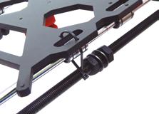
7 5 Fixing with straps 4 x lack strap 100 x 2.5 mm ssembly: Fix the smooth rods by positioning the straps as shown in the figures

 through the")
 into the bearing")
8 6 Preparing the tensioner C 1 x 1 x 1 x D E Pulley Printed Y axis tensioner for bearing 623ZZ C M3 x 20 mm screw D M3 x 25 mm screw 1 x 2 x E M3 nut ssembly: Insert the long screw (D) through the pulley and fix it with the two nuts. Insert the short screw (C) into the bearing tensioner as shown in the picture. 1 2


9 7 Preparing the motor C 1 x 1 x 3 x C Nema 17 motor Nema 17 bipolar stepper motor ( deg/step) Motor printed part Y axis Printed part to fasten the Nema 17 motor of Y axis to the threaded rods M3 x 10 mm screw Make sure that the orientation of the motor is correct. 1 2


10 8 Preparing the threaded rods (Part 1) C D 6 x 6 x 1 x 1 x E C D E M8 washer M8 nut Set from step 6 Set from step 7 M8 x 205 mm threaded rod 4 x ssembly: Fix the step 7 set to two of the threaded rods, securing them with the washers and nuts. Do the same with the step 6 set.
11 1 2

12 9 Preparing the threaded rods (Part 2) C 1 x 8 x 8 x C Set from step 8 M8 washer M8 nut ssembly: Put the washers and nuts onto the set assembled in the previous step, as shown in the picture. 1
13 2

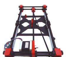
14 10 Joining the rods 1 x 1 x Set from step 9 Set from step 5 ssembly: ffix the four sets assembled in previous steps together, by inserting the ends of the rods into the holes of the corner printed parts. 1 2 Do not tighten the nuts completely, adjust them in step 17.


15 11 Fixing the structure C 8 x 8 x 1 x C M8 nut M8 washer Set from step


16 12 Preparing the aluminium base C 1 x 1 x 2 x C luminium base elt-holding printed part Y axis Part for holding the GT2 belt corresponding to Y axis M3 x 10 mm screw ssembly: Screw the printed part which will hold the belt onto the aluminium base. 1 2


17 13 Fixing the aluminium base with straps C 1 x 1 x 3 x C Set from step 11 Set from step 12 lack strap 100 x 2,5 mm ssembly: Join the sets from steps 11 and 12, fastening the ends with the straps. 1 2


18
 Part located")


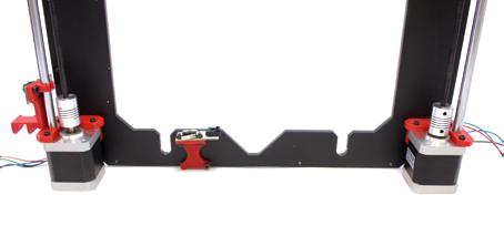
19 14 Preparing the endstop sensor of the base 1 x 1 x Printed Endstop part Y axis (base) Part located on the base of Y axis that incorporates a screw with a M3 nut to adjust the total stroke of the axis. It is complemented by the part that holds the endstop part to the frame. M3 x 25 mm screw 1 2


20 15 nchoring the endstop sensor to the base 1 x 1 x Set from step 13 Set from step


, and fit the belt (6).")


21 16 Fitting the Y axis belt C 1 x 1 x 4 x C GT2 6 mm x 1 m belt GT2 pulley (20 teeth) lack strap 100 x 2,5 mm For this step you will need a 2 mm llen wrench. ssembly: Turn the set over and place the pulley in the motor s axis, tightening it with the llen wrench (3). Loosen the screw to slacken the tensioner (5), and fit the belt (6). When the belt has been fitted, cut off the remaining part (7, 8, 9, 10, 11). lign the belt (12, 13). Tighten it by turning the screw of the tensioner with the 2 mm llen wrench (14)


22


23
 ssembly: Tighten all the nuts with the printed fixed spanner.")

24 17 Tightening all the nuts 1 x Printed fixed spanner 10 (M6), 13 (M8), 17 (M10) ssembly: Tighten all the nuts with the printed fixed spanner. Check that the base slides correctly with the smooth rods. You need to file the imperfections of the fixed spanner to make it fit well on the nuts. 1


25 18 Fitting the methacrylate base C 1 x 4 x 4 x C Methacrylate base Springs M3 x 25 mm screw ssembly: Fix the methacrylate base to the structure assembled in previous steps. To do this, join the four corners of the methacrylate base to the four sides of the aluminium base, using the screws and the springs. 1 2


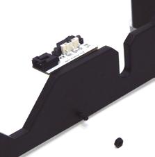
26 19 Preparing the endstop sensor in the frame C D 2 x 2 x 1 x 1 x C D M3 Nut M3 x 10 mm screw Printed Endstop frame part Y axis The part which fastens the Y axis endstop to the frame. It is complemented by the base part which is adjustable with the screw and M3 nut. Endstop frame Endstop part mounted on a PC with a LED indicator. 1 2


27 20 nchoring the endstop sensor to the frame C D 1 x 1 x 1 x 1 x C D Set from step 19 M3 nut M3 x 16 mm screw lack aluminium frame 1 2
28 3 4 5


29 21 Joining of Y axis with X and Z axis (Part 1) 1 x 1 x Y axis X and Z axis 1 2 The distance from the aluminium frame to the printed part has to be 9.1 cm.
 1 x 1 x")
, 13 (M8), 17")
30 22 Joining of Y axis with X and Z axis (Part 2) 1 x 1 x Set from step 21 Printed fixed spanner 10 (M6), 13 (M8), 17 (M10) 1
1 Assembly of the Y axis
 1 ssembly of the Y axis Q yclone 1 Preparing the side frames. x1 x1 x6 x12 E Printed part for right side Printed part for left side o not fully tighten the screws so that you will be able to insert the
List of components first steps
 1 First steps List of components first steps 2 x xial ball bearing 623ZZ 2 x Pulley axle X bearing 623ZZ 2 x Pulley axle Y bearing 623ZZ 1 x xle X right 1 x xle X left 1 x xle X tensioner bearing 623ZZ
Assembly of the Electronics
 6 ssembly of the Electronics List of components for the Electronics Ramps 1.4 (with 4 x Stepstick Drivers 4988 mounted) 3 x Endstop LD control Panel US cable, type, 1.8 metres 4 x Nema 17 motor cable 2
Assembly of the Electronics
 6 ssembly of the Electronics List of components for the Electronics Ramps 1.4 (with 4 x mounted Stepstick Drivers 4988) 3 x Endstop LD control panel 1.8 m type US cable 4 x Nema 17 motor cable 2 x 40 cm
3. X-axis assembly. 3. X-axis assembly. X axis guide. Written By: Josef Prusa manual.prusa3d.com/ Page 1 of 14
 3. X-axis assembly X axis guide Written By: Josef Prusa 2017 manual.prusa3d.com/ Page 1 of 14 Step 1 Getting the necessary tools 1.5mm & 2.5mm Allen key Needle-nose pliers Step 2 3D printed parts X-carriage
Prusa i3 Printer Assembly Guide
 Prusa i3 Printer Assembly Guide Special thanks to Carlos Sanchez and Miguel Sanchez for the graphics. All graphics captured from their great animation: http://www.carlos-sanchez.com/ Prusa3/ For copyright
Assembling the Electronics
 6 ssembling the Electronics List of components for the Electronics Ramps 1.4 (with 4 x Stepstick Drivers 4988 mounted) 3 x End-stop LD ontrol Panel US cable, type, 1.8 metres 4 x able motor Nema 17 2 x
Pi Instruction Manual. Mechanical
 Pi3 2014 Instruction Manual Document No MANUAL WBS Pi3 2014 DIY REV01 Mechanical 3D LabteK Model 1 / 37 Content Page Introduction 2 Printed Parts 3 1, Mechanical 4 1,1 Frame Assembly 6 1,2 Y Axis Assembly
Documentation version ASSEMBLY INSTRUCTIONS
 Documentation version 1.6.30 ASSEMBLY INSTRUCTIONS / 2 INTRODUCTION / 3 INTRODUCTION Target : Propose a visual assembly instruction guide of the MicroDelta Rework. Designers of the MicroDelta Rework :
Tensioners. Stock Program Type B, eccentric, toothed running surface. Polyurethane Timing Belt Drives
 Polyurethane Timing elt Drives Tensioners Type, eccentric, toothed running surface Type s run on ball bearings. The bearings are grease lubricated and up to C will experience no reduction in grease life.
Cam roller guide LF6S complete axis
 Y 1- MGE 1. Linear guides Z Mz Cam roller guide LFS complete axis X Mx M y [mm] B [mm] Fully assembled cam roller guide Stroke and trolley length can be individually selected Rail profile screwed onto
CONTENTS. Safety Instructions. Litto at a Glance. Bill of Materials. Before You Start. Z-Platform. Litto Frame pt.1. Litto Frame pt.2. Gantry pt.
 ASSEMBLY MANUAL CONTENTS Safety Instructions Litto at a Glance Bill of Materials Before You Start Z-Platform Litto Frame pt.1 Litto Frame pt.2 Gantry pt.1 Gantry pt.2 Gantry pt.3 Carriage Electronics /
ASSEMBLY MANUAL TINKERINE STUDIO. 3D Printer + Creative Solution
 + ASSEMBLY MANUAL 3D Printer + Creative Solution CONTENTS Safety Instructions Ditto at a Glance Bill of Materials Before You Start Z-Platform Ditto Frame pt.1 Ditto Frame pt.2 Gantry pt.1 Gantry pt.2 Gantry
Modix Big-60 Assembly Instructions Part 1
 Modix Big-60 Assembly Instructions Part 1 Version 1.0, October 2017 Menu 1. X Idler Pulley Assembly... 3 2. Connecting X Axis Brackets to Z Profiles... 4 3. Assemble X Rails on X Top Profiles... 6 4. Assemble
Maintenance Manual. Hephestos
 Hephestos 2016 Mundo Reader SL. All rights reserved. The reproduction, copying, distribution, publication or modification of this material is strictly prohibited unless carried out with the express prior
Documentation version ASSEMBLY INSTRUCTIONS
 Documentation version 1.1.0 ASSEMBLY INSTRUCTIONS / 2 INTRODUCTION / 3 INTRODUCTION Target : Provide a visual guide of the various steps required to assemble the «i3 Metal Motion» 3D printer. Designers
Cam roller guide LF12S complete axis
 Y -16 MGE. Linear guides Z Mz Cam roller guide LF1S complete axis X Mx M y [mm] B [mm] Fully assembled cam roller guide Stroke and trolley length can be individually selected Rail profile screwed onto
3. Extruder Assembly
 3. Extruder Assembly Guide for the assembly of the Extruder. Written By: Josef Prusa 2017 manual.prusa3d.com Page 1 of 22 Step 1 Get the necessary tools 2.5 and 1.5 mm Allen key Needle-nose pliers Step
REMOVAL & INSTALLATION
 REMOVAL & INSTALLATION CAUTION: This application is an interference engine. Do not rotate camshaft or crankshaft when timing belt is removed, or engine damage may occur. TIMING BELT Removal 1. Raise and
Documentation version 1.42 ASSEMBLY INSTRUCTIONS REV 1.1
 Documentation version 1.42 ASSEMBLY INSTRUCTIONS REV 1.1 / 2 INTRODUCTION / 3 INTRODUCTION Target : Prupose a visual guide of the differents steps to build and use a µdelta printer Designers : Hugo Flye
connected to innovation
 connected to innovation OMPRESSED IR NETWORKS, MPS ONEPT The MPS range MPS is a simple and reliable aluminium profile connection system for the installation of compressed air distribution networks. MPS
Assemble Manual of Geeetech Acrylic Prusa I3 (8mm)
") Assemble Manual of Geeetech Acrylic Prusa I3 (8mm) Warning: Shenzhen GETECH CO.,LTD. This kit contains tiny parts; please keep them away from kids under 3.. Building and operating 3D printer involves electricity,
Assemble Manual of Geeetech Acrylic Prusa I3 (8mm) Warning: Shenzhen GETECH CO.,LTD. This kit contains tiny parts; please keep them away from kids under 3.. Building and operating 3D printer involves electricity,
5. Extruder Assembly
 5. Extruder Assembly Guide for the assembly of the Extruder. Written By: Josef Prusa 2018 manual.prusa3d.com/ Page 1 of 24 Step 1 Get the necessary tools 2.5 and 1.5 mm Allen key Needle-nose pliers 2018
5. Extruder. 5. Extruder. Extruder guide. Written By: Dozuki System manual.prusa3d.com Page 1 of 16
 5. Extruder Extruder guide Written By: Dozuki System 2017 manual.prusa3d.com Page 1 of 16 Step 1 Get the necessary tools 2.5, 2 and 1.5 mm hex spanner Needle-nose pliers Step 2 3D printed parts Extruder
ABOVE-GROUND AUTOMATIC POOL COVERS
 ABOVE-GROUND AUTOMATIC POOL COVERS VALLESPIR MODEL INSTALLATION AND MAINTENANCE MANUAL SERIAL N : Revision number: 003-2008-01-01 TABLE OF CONTENTS - Personnel and material required for unloading and assembly
Replacing the sump. Copyright 2004 Volvo Car Corporation. All rights reserved.
 "VCC139128 EN 20100619" 1(6) Replacing the sump Special tools: 951 1205, 999 5460, 999 5716, 999 5717 Note! As the illustrations in this service information are used for different model years and / or
6204 Series Low-Volume Inserter
 204 Series Low-Volume Inserter /2012 MAINTENANCE MANUAL Mechanical description Mechanical description...51 General...52 Covers and plates...52 Electrical components...57 Feeder modules...0 Document feed...4
Assembly Instructions of Geeetech Prusa I3 A pro
 Assembly Instructions of Geeetech Prusa I3 A pro (Version 04-11-2016) CONTENT Safety Instructions... 3 Preparation... 4 1. Unfold the box and check the package... 1 2. Assemble Y axis... 1 3. Build the
 UNILINE www.motiontech.com.au bout Rollon Development of global business Continual expansion and optimization of the portfolio 1975 Parent company, Rollon S.r.l., founded in Italy 1991 Founding of Rollon
Engine, disassembly and
 Page 1 of 13 13-1 Engine, disassembly and assembly Ribbed belt, removing and installing Removing - Remove noise insulation -arrows-. - Remove bumper Repair Manual, Body Exterior, Repair Group 63 - Move
Assembly Instructions of Geeetech Aluminum Prusa I3
 Assembly Instructions of Geeetech Aluminum Prusa I3 CONTENT Safety Instructions... 3 Preparation... 4 1. Unfold the box and check the package... 1 2. Assemble Y axis... 1 3. Build the printing platform...
BFB 3000 UPGRADE KIT 1
 BFB 3000 UPGRADE KIT 1 D o c u m e n t N o : D 1 0 0 2 5 2 Page: 1 Summary This document provides instructions to fit the components from the BfB 3000 Upgrade kit. Please examine your upgrade kit the packs
mechanics Features Technical specification Ordering information Dimensioned drawings Aluminium profiles made by isel
 Panel profiles PP profiles For fast and easy erection of frames, benches and racks luminium, naturally anodised easy, very strong under load Top edge particularly suitable as a load-bearing cladding, also
Procedure Replacing a Cover
 Procedure 7.1 - Replacing a Cover Cover Removal 1. Remove two screws, one each side, from the front of the top cover. Remove the top cover. See Diagram 7.1. Diagram 7.1 - RBK 815 Covers Top Cover Left
Generator, removing and
 Page 1 of 14 27-26 Generator, removing and installing CAUTION! Disconnect the battery Ground (GND) strap before working on the electrical system. Notes: Before disconnecting the battery, determine the
MAINTENANCE INSTRUCTIONS
 MAINTENANCE INSTRUCTIONS ECOMAT EASY / GIROTEC WRS Version G0101 ECOMAT EASY H / GIROTEC WRS H Version G0301 ECOMAT PLUS / ECOMAT PLUS H Versions G0503 / G0603 V 2.0 Table of contents 1/3 1.0 Maintenance
Locks and handles 19
 19 19 25074 Complete CYLINDER LOCK : 1.47 kg : Complete cylinder lock with black outside plating. Including 3 keys and 2 brackets. Stroke: 50mm. 25147 EURO PROFILECYLINDER : 0.22 kg : Suitable for article
M-5220-MB Mustang GT Side Exhaust Kit INSTALLATION INSTRUCTIONS
 Please visit www.fordracingparts.com for the most current instruction information.!!! PLEASE READ ALL OF THE FOLLOWING INSTRUCTIONS CAREFULLY PRIOR TO INSTALLATION. AT ANY TIME YOU DO NOT UNDERSTAND THE
1. Product overview Basic-Line-Module AXN Product description Basic-Line-Module AXN 4-5. Guide system Roller guide 6 Drive system Gear belt 7
 Directory Page 1. Product overview Basic-Line-Module AXN 3 2. Product description Basic-Line-Module AXN 4-5 Guide system Roller guide 6 Drive system Gear belt 7 3. Basic-Line-Modul AXN 45-Z 8-9 AXN 65-Z
MT Series MTB 42 BELT DRIVEN LINEAR ACTUATOR
 MT Series MTB BELT DRIVEN LINEAR ACTUATOR LINEAR ACTUATOR TECHNOLOGY The MT Series offers a number of profile sizes with multiple design configurations to fit almost any application. TECHNICAL DATA FEATURES
Wood Grain Warrior Line Incognito hidden winch bumper installation instructions Lexus GX470
 Wood Grain Warrior Line Incognito hidden winch bumper installation instructions 2003-2009 Lexus GX470 Version 1.0-2016 Thank you for purchasing the Southern Style OffRoad Wood Grain Warrior Line Lexus
These Installation Instructions are valid for antennas in the following version :
 Installation Instructions 10 ft Antennas PA, PAL, PAD, PAX, PADX DA, UA, DAX, UDA, UXA HTT 81.222-11(e) These installation instructions have been written for qualified, skilled personnel. The antenna shall
Courtesy of CMA/Flodyne/Hydradyne Motion Control Hydraulic Pneumatic Electrical Mechanical (800)
") 01_1 Miniature st Headline_36 Ball Rail pt/14.4 Systems mm second line 2 Linear Motion and Assembly Technologies Miniature Ball Rail Systems Ball Rail Systems Roller Rail Systems Linear Bushings and Shafts
01_1 Miniature st Headline_36 Ball Rail pt/14.4 Systems mm second line 2 Linear Motion and Assembly Technologies Miniature Ball Rail Systems Ball Rail Systems Roller Rail Systems Linear Bushings and Shafts
HepcoMotion. SBD Sealed Belt Drive
 HepcoMotion SBD Sealed Belt Drive Introduction The HepcoMotion SBD is an exceptionally rugged, quiet and precise linear unit. It uses super-smooth Hepco LBG caged linear ball guides having such high load
Table of Contents. Prusa i3 Build Manual
 Table of Contents Forward... 4 1. Y-AXIS Frame... 5 1.1 Y-AXIS Long Sections...6 1.2 Y-Axis Rear Section (Motor)...7 1.3 Y-Axis Front Section (Idler)...9 1.4 Y-Axis Lower Frame Completed...10 2. Z-AXIS
These Installation Instructions are valid for antennas in the following version :
 Installation Instructions 8 ft Antennas PA, PAL, PAD, PAX, PADX DA, UA, DAX, UDA, UXA HTT 81.221-15 (e) These installation instructions have been written for qualified, skilled personnel. The antenna shall
Reproduction. Not for. Installation Instructions. Gearbox Replacement Kit. Part No WARNING REMOVING THE GEARBOX. Fits IS2600Z Models A B
 Installation Instructions Kit ontents Part No. Qty. escription Part No. Qty. escription 5025394 5 Nut, 3/8-16 ex Nylock lange 5104533 1 earbox, Right ngle 5025396 4 Nut, 1/2-13 ex Nylock lange Part No.
Mechanical Adjustments 6-Axis Adjustment and Mirror Adjustment
 Mechanical Adjustments -Axis Adjustment and Mirror Adjustment.1. Adjustment Specifications.2. Adjustment Procedure Overview.3. -Axis Adjustment.4. Adjusting The Mirror -1 .1..1. Adjustment Specifications
RA 800 Sauber Accessories Brush body. As at: 01/15/10 Time:21:28
 Accessories Brush body As at: 01/15/10 Time:21:28 Accessories Brush body As at: 01/15/10 Time:21:28 Pos. Description Reference 01 Allen-screw M 8x55 P...489 H 02 U-shim M 8 P...497 T 03 Roller 530.136
/2015. Roller and ball bars for easy and safe die change
 Roller and ball bars for easy and safe die change T-slot tolerances acc. to DIN 650 h h n a b c min. max. max. 18 H8 30 +2 12 +2 30 36 1,6 22 H8 37 +3 16 +2 38 45 1,6 28 H8 46 +4 20 +2 48 56 1,6 36 H8
These Installation Instructions are valid for antennas in the following version :
 Installation Instructions 8 ft Antennas PA, PAL, PAD, PAX, PADX DA, UA, DAX, UDA, UXA HTT 81.221-12(e) These installation instructions have been written for qualified, skilled personnel. The antenna shall
Building Instructions of Geeetech Prusa I3 M201
 Building Instructions of Geeetech Prusa I3 M201 (Version 11-25-2016) CONTENT Safety Instructions... 1 Preparation... 2 1. Assemble the threaded rods of Y axis... 3 2. Assemble the front and back support
Audi A8 ( ) MMI swivelling unit repair manual
 MMI swivelling unit repair manual") Audi A8 (2003-2007) MMI swivelling unit repair manual Tools which you will need: two pcs screwdriver (any kind, for vent removing ) (you can cover the metal part with any tape to prevent making scratches
Audi A8 (2003-2007) MMI swivelling unit repair manual Tools which you will need: two pcs screwdriver (any kind, for vent removing ) (you can cover the metal part with any tape to prevent making scratches
ABOVE-GROUND AUTOMATIC POOL COVER
 ABOVE-GROUND AUTOMATIC POOL COVER CAPCIR MODEL INSTALLATION AND MAINTENANCE MANUAL Serial N : Revision number: 004-2008-01-01 TABLE OF CONTENTS - Personnel and material required for unloading and assembly
EG-34 ENGINE MECHANICAL TIMING BELT COMPONENTS FOR REMOVAL AND INSTALLATION
 EG34 TIMING BELT COMPONENTS FOR REMOVAL AND INSTALLATION EG35 TIMING BELT REMOVAL (See Components for Removal and Installation) 1. DISCONNECT NEGATIVE TERMINAL CABLE FROM BATTERY CAUTION: Work must be
ROSTA Motorbases. Self-tensioning Motor Mounts for all Friction Belt Drives slippage-free belt protecting maintenance-free ROSTA
 Motorbases Self-tensioning Motor Mounts for all Friction elt Drives slippage-free belt protecting maintenance-free Customer enefits of the Rosta Motorbases in Friction elt Drives M 7 Offers short-term
Z TECHNICAL INSTRUCTIONS
 ÍNDICE: Z40 2.0 TECHNICAL INSTRUCTIONS 1.- Error list 2.- Replace the control board 3.- Opening the machine 4.- Replace the power board 5.- Dismantling motor and gear box 6.- Assembly of gear box 7.- Pushing
Linear Drive with Toothed Belt Series OSP-E..B. Contents Description Overview Technical Data Dimensions Order Instructions 46
 Linear Drive with Toothed Belt Contents Description Page Overview 35-38 Technical Data 39-43 Dimensions 44-45 Order Instructions 46 35 The System Concept ELECTRIC LINEAR DRIVE FOR POINT-TO-POINT APPLICATIONS
ECOLINE: AFFORDABLE AND INNOVATIVE LINEAR BEARINGS
 ECOLINE: FFORDBLE ND INNOVTIVE LINER BERINGS ECOLINE s products have been designed to fit in applications where quality movement is needed at a low price. The patented design offers a well-protected, smooth
SERVICE BULLETIN SB.DSL rev02
 DSL 505 Rear Delt / Pec Fly Cable Repair Applies to DSL 505 Rear Delt / Pec Fly built prior to 5/16/2017 Issue/Symptoms On some machines using the 1/8 diameter lift cables, the cam cables may twist and
Precision Modules PSK. The Drive & Control Company
 Precision Modules PSK The Drive & Control Company 2 Bosch Rexroth Coporation Precision Modules PSK R310A 2414 (2008.07) Linear Motion and Assembly Technologies Ball Rail Systems Roller Rail Systems Linear
Profile guide/actuator - RK Compact
 Profile guide/actuator - RK Compact Slimline short-stroke linear actuator for hand adjustment with excellent price-performance ratio Control knob with vernier Simple adjustment of carriage Backlash of
2005 Hyundai Tucson LX. On some models, engine is equipped with a timing belt and timing chain. Inspect timing chain when replacing timing belt.
 TIMING BELT NOTE: On some models, engine is equipped with a timing belt and timing chain. Inspect timing chain when replacing timing belt. Removal 1. Remove the engine cover. See Fig. 1. 2. Remove right
RK Monitor Mounting... page 254. GT page 264. GT 50, 60, page 274. Support arm / equipment carrier system
 Support arm / equipment carrier system RK Monitor Mounting... page 254 GT 48... page 264 GT 50, 60, 80... page 274 Support arm / equipment carrier system RK Monitor Mounting All purpose mounting for monitors,
Service and Repair SERVICE POINTS OF REMOVAL. Select Vehicle New TSBs Technician's Reference Mitsubishi 3000GT V6-2972cc 3.
 1 of 12 5/4/2008 10:31 PM Home Account Contact ALLDATA Log Out Help METRO TOYOTA Select Vehicle New TSBs Technician's Reference 1992 Mitsubishi 3000GT V6-2972cc 3.0L DOHC Vehicle Level Engine, Cooling
Rectangular profiles RE 40
 8.3 luminium profiles Rectangular profiles Features Universal precision, clamping and machining surface s a stabiliser for machine and subframe constructions luminium, ly anodised Produced in accordance
DOOR KIT P/N , APPLICATION BEFORE YOU BEGIN KIT CONTENTS. Verify accessory fitment at Polaris.com.
 DOOR KIT P/N 2882561, 2882562 APPLICATION Verify accessory fitment at Polaris.com. BEFORE YOU BEGIN Read these instructions and check to be sure all parts and tools are accounted for. Please retain these
Handle: 20" Chain: 25"
 Handle: 6" JTC-1147 6" CHAIN WRENCH Chain: 18" (400mm) Handle: 20" Chain: 25" JTC-1149 20" CHAIN WRENCH JTC-1150 12" STRAP WRENCH Handle: 12" Strap length: 36" JTC-1355 EUROPEAN DOOR HINGE / HANDLE KIT
The new performance class...
 The new performance class... 10/2017 EP(X)-II 30/40 EP(X)-II 30/40 twin tube actuator The latest generation of twin tube units Move-Tec EP(X)-II 30/40 Your application takes centre stage slow langsam A
Distribution blocks Distribution system
 nclosures & accessories new repar_043.eps The solution for > lectrical distribution Single-pole distribution blocks Multi-pole distribution bar repar_044.eps Strong points > xtensive range > asy integration
VALVE TIMING CHECK-TIMING BELT COVER INSTALLED
 TIMING BELT SERVICE VALVE TIMING CHECK-TIMING BELT COVER INSTALLED 1. Remove number one spark plug. 2. Using a dial indicator; set number one cylinder to TDC on the compression stroke. 3. Remove the access
2003 Hyundai Truck Santa Fe V6-3.5L
 Page 1 of 12 2003 Hyundai Truck Santa Fe V6-3.5L Vehicle» Engine, Cooling and Exhaust» Engine» Timing Belt» Service and Repair Page 2 of 12 REMOVAL 1. Remove the wheel of passenger side. 2. Remove the
Features. Multi mover available. High tensile timing belt. Customized options. Easy maintenance. 5 Drive pulley (0:Standard, 2:Shaft type)
") TPC motion MT 40, 60, 0, 0 Features Track roller guide & elt type unit Multi mover available Various axis combination High tensile timing belt Customized options Easy maintenance How to order 1 2 3 4 MT
TPC motion MT 40, 60, 0, 0 Features Track roller guide & elt type unit Multi mover available Various axis combination High tensile timing belt Customized options Easy maintenance How to order 1 2 3 4 MT
Roller guide actuator/guides - SQ /SQZ
 Roller guide actuator/guides - SQ /SQZ Timing-belt unit with optimum connecting options due to slots in guide profile/carriage Fixing slots 9Easy 9 fixing of linear actuator 9Simple 9 connection of accessories
1999 Honda Accord DX
 Installation 1. Clean tensioner pulleys. Ensure cylinder No. 1 is at TDC by aligning dimple on timing belt drive pulley with pointer on oil pump housing. See Fig. 4. Ensure camshaft pulley TDC marks are
AUTOMATIC POOL COVER. Serial number: ENGLISH SOLAR CARLIT MODEL INSTALLATION MANUAL AND MAINTENANCE /18 Revision number
 AUTOMATIC POOL COVER SOLAR CARLIT MODEL INSTALLATION MANUAL AND MAINTENANCE Serial number: Revision number: 008-2008-01-31 - 1 -/18 Revision number 008-2008-01-31 TABLE OF CONTENTS - Personnel and material
Sizes 50, 65, 80. Presence of internal channels for re-lubrication Large range of axis mounting accessories
 > Series 5E electromechanical axis C_Electrics > 207 Series 5E electromechanical axis New models Sizes 50, 65, 80 Multiposition system with transmission of the movement with toothed belt Suitable for high
Timing Belt: Service and Repair. Toyota Truck Sienna LE V6-3.0L (1MZ-FE) 2002
 2002") Timing Belt: Service and Repair Toyota Truck Sienna LE V6-3.0L (1MZ-FE) 2002 REMOVAL 1. REMOVE OUTER FR COWL TOP PANEL ASSEMBLY 2. REMOVE RH FRONT WHEEL 3. REMOVE RH FENDER APRON SEAL 4. REMOVE GENERATOR
Timing Belt: Service and Repair Toyota Truck Sienna LE V6-3.0L (1MZ-FE) 2002 REMOVAL 1. REMOVE OUTER FR COWL TOP PANEL ASSEMBLY 2. REMOVE RH FRONT WHEEL 3. REMOVE RH FENDER APRON SEAL 4. REMOVE GENERATOR
Rotational Kinematics and Dynamics Review
 Rotational Kinematics and Dynamics Review 1. The Earth takes slightly less than one day to complete one rotation about the axis passing through its poles. The actual time is 8.616 10 4 s. Given this information,
Material: Hinge Parts: zinc die, matt chrome plated, or zinc die, matt black. Pin: stainless steel Nut plate: steel, zinc plated
 4-249 Hinge Pr01 180 Small elegant hinge. 180 Opening. Adjustments are possible with respective bores provided. The nut plate can be mounted in different ways, according to the application. zinc die, matt
DISASSEMBLY. SORENTO(BL) > 2004 > G 3.5 DOHC > Engine Mechanical System
 > 2004 > G 3.5 DOHC > Engine Mechanical System") SORENTO(BL) > 2004 > G 3.5 DOHC > Engine Mechanical System DISASSEMBLY 1. Remove the engine cover. 2. Disconnect the battery negative terminal. 3. Disconnect the radiator lower hose. 4. Disconnect the
SORENTO(BL) > 2004 > G 3.5 DOHC > Engine Mechanical System DISASSEMBLY 1. Remove the engine cover. 2. Disconnect the battery negative terminal. 3. Disconnect the radiator lower hose. 4. Disconnect the
SKY TRACK SYSTEM _ Intro
 SKY TRACK SYSTEM _ Intro 82 lighting Ideal for all photo and video studios where the floor needs to be kept totally clear of power cables and lighting stands, the Sky Track System permits rapid manoeuvre
MINI BIKE-2016 MB 200 Set-up Instruction
 MINI BIKE-2016 MB 200 Set-up Instruction 2016-06-01 1. Install rear shocks: open the crate and install the rear shocks with bolt M10x1.25x40 and self-locking nut M10x1.25. The requested torque is 37-44N.m
AUTOMATIC POOL COVER. Serial number: ENGLISH N'CARLIT MODEL INSTALLATION MANUAL AND MAINTENANCE /18 Revision number
 AUTOMATIC POOL COVER N'CARLIT MODEL INSTALLATION MANUAL AND MAINTENANCE Serial number: Revision number: 002-2012-10-05 - 1 -/18 Revision number 002-2012-10-05 TABLE OF CONTENTS UNLOADING... 2 TOOLS REQUIRED
1995 Mitsubishi Montero LS. Ensure timing marks are aligned. Mark timing belt direction of rotation.
 TIMING BELT NOTE: Ensure timing marks are aligned. Mark timing belt direction of rotation. Removal 1. Disconnect negative battery cable. Drain engine coolant. Remove engine coolant reservoir tank, fan
Reproduction. Not for. Installation Instructions. IS2600Z Gearbox Replacement. Replacing the Gearbox and Mount Bracket WARNING. Removing the Gearbox
 Installation Instructions WRNIN Remove the ignition key prior to performing maintenance on the unit. IS2600Z earbox Replacement its erris IS2600Z omestic Models allout Part escription Qty Number 5413882
SECTION 6C POWER STEERING GEAR TABLE OF CONTENTS
 SECTION 6C POWER STEERING GEAR TABLE OF CONTENTS Description and Operation... 6C2 Power Rack and Pinion... 6C2 Component Locator... 6C3 Diagnostic Information and Procedures... 6C4 Power Steering Rack
MAGNUM SMA8 and SMH10 Assembly Manual
 MAGNUM SMA8 and SMH10 Assembly Manual Please note that this manual uses a MAGNUM SMA8 in all the images. The SMH10 has some very slightly different parts, but the assembly process is identical. Step 1
Part # Camber Caster Plates Ford Mustang All Ford Mustang GT500
 Part # 24220 Camber Caster Plates 2005-2010 Ford Mustang All 2007-2014 Ford Mustang GT500 J&M Products once again outdoes our competitors with these fully adjustable (Protected under US Patent No. 8,820,759
160S Rewind Option Kit Installation Instructions
 Installation Instructions GENERAL This kit includes the parts and documentation necessary to install the Media Rewind Option into the Zebra 160S printer. Read these instructions thoroughly before attempting
Linear Actuator with Toothed Belt Series OSP-E..B
 Linear Actuator with Toothed Belt Series OSP-E..B Contents Description Data Sheet No. Page Overview 1.20.001E 21-24 Technical Data 1.20.002E-1 to 5 25-29 Dimensions 1.20.002E-6 30 Order Instructions 1.20.002E-7
M Damper Mount Linkage Kit Installation. Item Description Quantity Item Description Quantity Nuts 2
 FANs 268.1, 1628.3 Installation Bulletin M9000-150 Issue Date 0796 M9000-150 Damper Mount Linkage Kit Installation 21 18 19 20 2 22 17 2 4 3 2 15.5 393.7 1 17 16 15 11 13 12 8 9 10 2 5 Note: Damper mount
Assembly Instructions. General Information. Installation Instructions. 12, 15 and 20 Series Drill Small Seeds Option. Used with:
 Installation Instructions! Used with: 1200, 1210 and 1220 Drills 1500, 1510 and 1520 Drills 2000, 2010 and 2020 Drills 12, 15 and 20 Series Drill Small Seeds Option When you see this symbol, the subsequent
POWER TRANSMISSION PARTS. Spare parts in-stock when you need them. Metric Timing Pulleys & Belt Drives.
 POWER TRNSMISSION PRTS Spare parts in-stock when you need them Metric Timing Pulleys & elt Drives Metric T & T Pulley & elt Drives The metric T & T series was created to meet industries need for polyurethane
Used for installation and dismantling designs such as pipes of almost any diameter. Handle: 20" Chain: 25"
 JTC-1147 6" CHAIN WRENCH Used for installation and dismantling designs such as pipes of almost any diameter. Handle: 6" Chain: 18" (400mm) JTC-1149 20" CHAIN WRENCH Used for installation and dismantling
Installation Instructions 6 ft Antennas Adv. Backring (with T-Mount) PA, PAL, PAD, SP, PAX, PADX, SPX DA, UA, SU, SD, SDF, DAX, UDA, UXA, SDX, SUX
 PA, PAL, PAD, SP, PAX, PADX, SPX DA, UA, SU, SD, SDF, DAX, UDA, UXA, SDX, SUX") Installation Instructions 6 ft Antennas Adv. Backring (with T-Mount) PA, PAL, PAD, SP, PAX, PADX, SPX DA, UA, SU, SD, SDF, DAX, UDA, UXA, SDX, SUX NMT 628-00(e) DA, UA, SU, SD, SDF DAX, UDA, UXA, SDX,
Installation Instructions 6 ft Antennas Adv. Backring (with T-Mount) PA, PAL, PAD, SP, PAX, PADX, SPX DA, UA, SU, SD, SDF, DAX, UDA, UXA, SDX, SUX NMT 628-00(e) DA, UA, SU, SD, SDF DAX, UDA, UXA, SDX,
MTB 42 Belt Driven Linear Actuator
 LINEAR ACTUATOR TECHNOLOGY MT Series MTB Belt Driven Linear Actuator The MT Series offers a number of profile sizes with multiple design configurations to fit almost any application. TECHNICAL DATA features
V SWISS MADE LINEAR TECHNOLOGY
 Excerpt from main catalogue inear modules V 11-15 SWISS MDE INER TECHNOOGY ine Tech inear modules Table of contents Product overview 6 7 Design fundamentals / ubrication / Maintenance 8 Profile cross-sections
Drive. Guide. Profile rail guide with ball circuit and wiper smooth torsion stiff. Intake flange. Adapter plate
 Linear Rail Slides Highlights Drive Double acting pneumatic cylinder maximum drive force in extend and retract movement pressure force up to 1 N Guide Profile rail guide with ball circuit and wiper smooth
Zeiss ZAT Cube Assembly Procedure
 1.1.1 The ZAT cube assembly has two filter retainer rings; one is located on the Exciter side and one is on the Emitter side as shown below. Note that the Exciter housing is marked with a red dot and the