|
|
|
- Randell Chase
- 5 years ago
- Views:
Transcription
1 UNILINE

2 bout Rollon Development of global business Continual expansion and optimization of the portfolio 1975 Parent company, Rollon S.r.l., founded in Italy 1991 Founding of Rollon GmbH in Germany 1995 Expansion of headquarters to new 4,000 m 2 factory ssembly starts in Germany Quality management certified to ISO Rollon B.V. in the Netherlands and Rollon Corporation in the US are founded Expansion of German branch to new 1,000 m 2 plant 1999 Founding of Rollon S..R.L. in France Environmental management certified to ISO Rollon s.r.o. founded in the Czech Republic 2001 Expansion of headquarters to new 12,000 m 2 manufacturing plant 2007 Restructuring of the GmbH and alignment of production in Germany to customer-specific adaptations Takeover of the assets of a manufacturer of linear rail systems 2008 Expansion of sales network in Eastern Europe and sia Founded in 1975, Rollon manufactured high-precision linear roller bearings for the machine tool industry. Early on, Rollon started manufacturing linear bearings based on the bearing-cage design. In 1979, the Compact Rail self-aligning linear bearings joined the Telescopic Rail industrial drawer slides and Easy Rail linear bearings and became the basis of the strong foundation on which the company is building upon today. Continuing optimization of these core products still remains one of the most important goals at Rollon. The development of the patented Compact Rail linear bearing, which uses different proprietary rail profiles and highprecision radial ball bearing sliders, enables the compensation of height and angle mounting defects in applications, and is only one example of the continuing efforts to innovative the development of our existing product families. In the same manner, we continually introduce innovative new product familiesdisplaying our continuing product development and optimization in the industry. These include: 1994 Light Rail - full and partial extension telescopic in lightweight design 1996 Uniline - belt driven linear actuators 2001 Ecoline - economical aluminum linear actuators 2002 X-Rail - inexpensive formed steel linear guides 2004 Curviline - curved monorail profile rail guide with roller carriages 2007 Monorail - miniature sizes and full sized Each further innovation of our linear bearings is built upon the our extensive knowledge of the nine product families in production today as well as on the current market demands. Rollon is the ultimate linear technology for any application needs.
3 Content 1 Product explanation Ready-to-install linear axes 2 Technical Data Performance characteristics and remarks Load ratings, moments and characteristic data C E ED H 3 Product dimensions version L with long slider version D with double slider C C version L with long slider C version D with double slider E E version L with long slider E version D with double slider ED ED version L with long slider ED version D with double slider H
4 Content 4 ccessories dapter plates Connection plates Fixing clamp PF-2 T-nut, 100 drive shaft 100 conical fitting device C-10M01 5 Technical information Static load Calculation formulae Service life Linear accuracy, Repeat accuracy Synchronous use of the linear units in pairs, Linear units with extended strokes, Length and stroke tolerances, Working temperature Lubrication Belt tension Determination of the motor torque, Installation instructions Ordering key Ordering key with explanations Portfolio 4

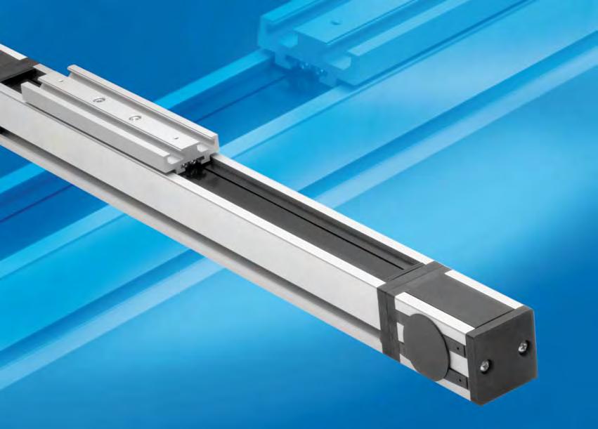
5 Product explanation 1 Product explanation Uniline is the product family of ready-to-install linear axes Fig. 1 Uniline is the product family of ready-to-install linear axes. They consist of internal Compact Rail roller sliders and steel-reinforced polyurethane belts in a rigid aluminium profile. Longitudinal seals enclose the system. This arrangement provides the best protection for the axis from soiling and damage. The guide rails are arranged in the four product series in different combinations for a wide range of applications. The use of one or several sliders provides greater variation. The most important characteristics: Compact design Protected internal linear guides High traversing speeds Grease-free operation possible (depending on the application. For further information, please contact our pplication Engineering epartment) High versatility Long traverses Versions with long or several sliders available in one linear axis Preferred areas of application: Handling and automation Multi-axis gantries Packaging machines Cutting machines Displaceable panels Painting installations Welding robots Special machines 5
6 1 Product explanation In the series, the fixed bearing rail (T-rail) is mounted horizontally in the aluminium profile. Versions with long (L) or double (D) sliders in one axis are possible. Fig. 2 C In the C series, the fixed bearing rail (T-rail) and the compensating bearing rail (U-rail) are mounted in the aluminium profile vertically. Versions with long (L) or double (D) sliders in one axis are possible. Fig. 3 E In the E series, the fixed bearing rail (T-rail) is mounted horizontally in the aluminium profile, and the compensating bearing rail (U-rail) is flanged to the profile on the outside as moment support. Versions with long (L) or double (D) sliders in one axis are possible. Fig. 4 ED In the ED series, a compensating bearing rail (U-rail) is mounted horizontally in the aluminium profile, and, for increased moment support, two further compensating bearing rails (U-rail) are flanged to the profile externally. Versions with long (L) or double (D) sliders in one axis are possible. Fig. 5 H In the H series, the compensating bearing rail (U-rail) is mounted horizontally in the aluminium profile. The H series is used as compensating bearing axis for load absorption of radial forces and, in combination with the other series, as support bearing for the resulting moments. Versions with long (L) or double (D) sliders in one axis are possible. Fig
 (depending on the application) Temperature range: -20 C to +80 C (-4 F to 176 F ) Max. traverse in a profile: 5,600 mm ( 220.")
7 Technical data 2 Technical data Fig. 7 Performance characteristics: vailable sizes: : 40, 55, 75, 100 s C and E: 55, 75 ED: 75 H: 40, 55, 75 Max. traversing speed: 9 m/s (354 in/s) (depending on the application) Temperature range: -20 C to +80 C (-4 F to 176 F ) Max. traverse in a profile: 5,600 mm ( in) (depending on the application, size and slider selection) Repeat accuracy: 0.1mm ( in) Linear guiding accuracy: 0.8 mm ( in) Length and stroke tolerances: For strokes <1 m: +0 mm to +10 mm (+0 in to 0.4 in) For strokes >1 m: +0 mm to +15 mm (+0 in to 0.59 in) Remarks: Different adapter plates for mounting with motor and gearbox Versions with long or several sliders in one linear axis available Different connection bores and clutches available for the motor shaft Linear axes with longer strokes (combined linear axes) possible Please specify if you want to use the linear axes in pairs by means of a synchronous shaft The max. load in vertical use depends on the standard belt tension 7
8 2 Technical data Load ratings, moments and characteristic data C 0ax M x M z M y C 0rad Fig. 8 C [N] C 0rad [N] C 0ax [N] M x [Nm] M y [Nm] M z [Nm] L* to to D* to to L* to to D* to to L* to to D* to to L* D* to to Tab. 1 * Note: For the dimensions of the different models, please refer to chapter 3 Product dimensions, p. 16ff For the calculation of the allowed moments, please observe pages 41ff 8
9 Technical data 2 Characteristic data Standard belt tension [N] Moment at no load [Nm] Max. traversing speed [m/s] Max. acceleration [m/s²] Repeat accuracy Compact Rail guiding rail TLV18 TLV28 TLV43 TLV63 Slider type CS18 spec. CS28 spec. CS43 spec. CS63 spez. Moment of inertia Iy [cm 4 ] Moment of inertia Iz [cm 4 ] Pitch diameter of pulley [m] Moment of inertia of each pulley [gmm²] Stroke per shaft revolution Mass of slider [g] Weight with zero stroke [g] Weight with 1 m stroke [g] Belt length [m] 2 x stroke x stroke x stroke x stroke Mass of belt [g/m] Tab
10 2 Technical data C C 0ax M x M z M y C 0rad Fig. 9 C [N] C 0rad [N] C 0ax [N] M x [Nm] M y [Nm] M z [Nm] C C55-L* to to 96 C55-D* to to 555 C C75-L* to bis 311 C75-D* to to 2268 Tab. 3 * Note: For the dimensions of the different models, please refer to chapter 3 Product dimensions, p. 16ff For the calculation of the allowed moments, please observe pages 41ff 10
11 Technical data 2 Characteristic data C55 C75 Standard belt tension [N] Moment at no load [Nm] Max. traversing speed [m/s] 3 5 Max. acceleration [m/s²] Repeat accuracy Compact Rail guiding rail TLV18 / ULV18 TLV28 / ULV28 Slider type 2 CS18 spec. 2 CS28 spec. Moment of inertia Iy [cm 4 ] Moment of inertia Iz [cm 4 ] Pitch diameter of pulley [m] Moment of inertia of each pulley [gmm²] Stroke per shaft revolution Mass of slider [g] Weight with zero stroke [g] Weight with 1 m stroke [g] Belt length [m] 2 x stroke x stroke Mass of belt [g/m] Tab
![2 Technical data E C 0ax M x M z M y C 0rad Fig. 10 C [N] C 0rad [N] C 0ax [N] M x [Nm] M y [Nm] M z [Nm] E55 4260 2175 1500 25.5 43.4 54.](/docs-images/86/93857058/images/12-0.jpg "4 E55-L* 8520 4350 3000 51 165 to 450 239 to 652 E55-D* 8520 4350 3000 51 450 to 4605 652 to 6677 E75 12280 5500 3710 85.")
12 2 Technical data E C 0ax M x M z M y C 0rad Fig. 10 C [N] C 0rad [N] C 0ax [N] M x [Nm] M y [Nm] M z [Nm] E E55-L* to to 652 E55-D* to to 6677 E E75-L* to to 2282 E75-D* to to Tab. 5 * Note: For the dimensions of the different models, please refer to chapter 3 Product dimensions, p. 16ff For the calculation of the allowed moments, please observe pages 41ff 12
13 Technical data 2 Characteristic data E55 E75 Standard belt tension [N] Moment at no load [Nm] Max. traversing speed [m/s] 3 5 Max. acceleration [m/s²] Repeat accuracy Compact Rail guiding rail TLV28 / ULV18 TLV43 / ULV28 Slider type CS28 spec. / CP 18 CS43 spec. / CP 28 Moment of inertia Iy [cm 4 ] Moment of inertia Iz [cm 4 ] Pitch diameter of pulley [m] Moment of inertia of each pulley [gmm²] Stroke per shaft revolution Mass of slider [g] Weight with zero stroke [g] Weight with 1 m stroke [g] Belt length [m] 2 x stroke x stroke Mass of belt [g/m] Tab
14 2 Technical data ED C 0ax M x M z M y C 0rad Fig. 11 C [N] C 0rad [N] C 0ax [N] M x [Nm] M y [Nm] M z [Nm] ED ED75-L* to to 2282 ED75-D* to to Tab. 7 * Note: For the dimensions of the different models, please refer to chapter 3 Product dimensions, p. 16ff For the calculation of the allowed moments, please observe pages 41ff Characteristic data ED75 Standard belt tension [N] 1000 Moment at no load [Nm] 1.5 Max. traversing speed [m/s] 5 Max. acceleration [m/s²] 15 Repeat accuracy 0.1 Compact Rail guiding rail Slider type ULV43 / ULV28 CS43 spec. / CS28 spec. Moment of inertia Iy [cm 4 ] 127 Moment of inertia Iz [cm 4 ] 172 Pitch diameter of pulley [m] Moment of inertia of each pulley [gmm²] Stroke per shaft revolution 160 Mass of slider [g] 3770 Weight with zero stroke [g] 9850 Weight with 1 m stroke [g] Belt length [m] 2 x stroke Mass of belt [g/m] 185 Tab
![Technical data 2 H C 0ax M z M y C 0rad M x Fig. 12 C [N] C 0rad [N] C 0ax [N] M x [Nm] M y [Nm] M z [Nm] H40 1530 820 13.1 H40-L* 3060 1640 61 to 192 H40-D* 3060 1640 192 to 1558 H55 4260 2175 54.](/docs-images/86/93857058/images/15-0.jpg "5 H55-L* 8520 4350 0 0 0 239 to 652 H55-D* 8520 4350 652 to 6677 H75 12280 5500 209 H75-L* 24560 11000 852 to 2282 H75-D* 24560 11000 2288 to 18788 Tab.")
15 Technical data 2 H C 0ax M z M y C 0rad M x Fig. 12 C [N] C 0rad [N] C 0ax [N] M x [Nm] M y [Nm] M z [Nm] H H40-L* to 192 H40-D* to 1558 H H55-L* to 652 H55-D* to 6677 H H75-L* to 2282 H75-D* to Tab. 9 * Note: For the dimensions of the different models, please refer to chapter 3 Product dimensions, p. 16ff For the calculation of the allowed moments, please observe pages 41ff Characteristic data H40 H55 H75 Max. traversing speed [m/s] Max. acceleration [m/s²] Repeat accuracy Compact Rail guiding rail ULV18 ULV28 ULV43 Slider type CS18 spec. CS28 spec. CS43 spec. Moment of inertia Iy [cm 4 ] Moment of inertia Iz [cm 4 ] Mass of slider [g] Weight with zero stroke [g] Weight with 1 m stroke [g] Tab
16 3 Product dimensions Product dimensions 40 system 42, M4 threads 15 7,5 Z Slider S Stroke Z J K 2,2 8,2 16,5 B 9 H Fig. 13 B H J K S Z Stroke* Tab. 11 * Maximum stroke for a single-piece guiding rail. For longer strokes, see p. 45, Tab motor connection E Section - C G V W V F F N I M M Bore diameter * * For information on the motor connection bores, see ordering key bb. 14 C* E F G* I M N V W Ø 14,9 2.3 Ø Tab. 12 * For the position of the T-nuts when using our motor adapter plates, see p. 34ff 16
17 Product dimensions system Z Slider S Stroke Z Fig. 15 B D H J K S X Y Z Stroke* * Maximum stroke for a single-piece guiding rail. For longer strokes, see p. 45, Tab. 48 Tab motor connection C G E F I 2,2 J Y K X H D B F N 8,2 16,5 9 Section - V W V Bore diameter * M M * For information on the motor connection bores, see ordering key Fig. 16 C* E F G* I M N V W Ø Ø Ø Ø * For the position of the T-nuts when using our motor adapter plates, see p. 34ff Tab
18 3 Product dimensions 100 system M6 threads (on both sides) M8 threads Z1 Slider S Stroke Z2 J K 6 10, ,1 H D B 1 Fig B D H J K S Z 1 Z 2 Stroke* * Maximum stroke for a single-piece guiding rail. For longer strokes, see p. 45, tab. 48 Tab
19 Product dimensions motor connection model Motor connection via key 4 M6 threads (on both sides) G G N I C C M Bore diameter * 1 * For information on the motor connection bores, see ordering key ** For information on the motor drive shaft, see chapter ccessories, p. 38, fig. 47 Fig C G I M N Ø 39,5 4 Ø 68 Tab motor connection model B Motor connection by means of conical fitting device 4 M6 threads (on both sides) G G N I M C C 1 Bore diameter * * See chapter ccessories, p. 39, fig. 48 Fig C G I M N Ø 39,5 4 Ø 68 Tab
20 3 Product dimensions version L with long slider 40L system 42,5 = = 6 M4 threads 7,5 15 Z Sn Stroke Z Fig. 20 S min S max Sn Z Stroke* 40L Sn = S min + n Tab. 18 * Maximum stroke for a single-piece guiding rail and a maximum slider plate length S max For longer strokes, see p. 45, tab L 75L system Z Sn Stroke Z Fig. 21 S min S max Sn Z Stroke* 055-L Sn = S min + n L Sn = S min + n Tab. 19 * Maximum stroke for a single-piece guiding rail and a maximum slider plate length S max For longer strokes, see p. 45, tab
21 Product dimensions 3 100L system M6 threads (on both sides) M8 threads Z Sn Stroke Z 1 2 Fig. 22 S min S max Sn Z 1 Z 2 Stroke* 100L Sn = S min = S max Tab. 20 * Maximum stroke for a single-piece guiding rail and a maximum slider plate length S max For longer strokes, see p. 45, tab
22 3 Product dimensions version D with double slider 40D system 4 M4 threads Z 42,5 80 Slider S Stroke Z 7,5 15 Ln 4 M4 threads Fig. 23 S L min L max ** Ln Z Stroke* 40D Ln = Lmin + n Tab. 21 * Maximum stroke for a single-piece guiding rail and a minimum slider plate distance L min ** Maximum distance L max between the centres of slider plates at a stroke of 0 mm For longer strokes, see p. 45, tab D 75D system Z Slider S Slider S Stroke Z Ln Fig. 24 S L min L max ** Ln Z Stroke* 55D Ln = L min + n D Ln = L min + n Tab. 22 * Maximum stroke for a single-piece guiding rail and a minimum slider plate distance L min ** Maximum distance L max between the centres of slider plates at a stroke of 0 mm For longer strokes, see p. 45, tab
23 Product dimensions 3 100D system Z1 Slider S Slider S Stroke Z Ln Fig. 25 S L min L max ** Ln Z 1 Z 2 Stroke* 100D Ln = L min + n Tab. 23 * Maximum stroke for a single-piece guiding rail and a minimum slider plate distance L min ** Maximum distance L max between the centres of slider plates at a stroke of 0 mm For longer strokes, see p. 45, tab
24 3 Product dimensions C C55 C75 system Z Slider S Stroke Z 2,2 J Y K X H 8,2 16,5 9 B Fig. 26 B H J K S X Y Z Stroke* C C * Maximum stroke for a single-piece guiding rail. For longer strokes, see p. 45, tab. 48 Tab
25 Product dimensions 3 C55 C75 motor connection F I Bore diameter * Section - V W V N C G E M F M * For information on the motor connection bores, see ordering key Fig. 27 C* E F G* I M N V W C Ø Ø C Ø 29, Ø Tab. 25 * For the position of the T-nuts when using our motor adapter plates, see p. 34ff 25
26 3 Product dimensions C version L with long slider C55L C75L system Z Slider Sn Stroke Z Fig. 28 S min S max Sn Z Stroke* C55L Sn = S min + n C75L Sn = S min + n Tab. 26 * Maximum stroke for a single-piece guiding rail and a maximum slider plate length S max For longer strokes, see p. 45, tab. 48 C version D with double slider C55D C75D system Z Slider S Slider S Stroke Z Ln Fig. 29 S L min L max ** Ln Z Stroke* C55D Ln = L min + n C75D Ln = L min + n Tab. 27 * Maximum stroke for a single-piece guiding rail and a minimum slider plate distance L min ** Maximum distance L max between the centres of slider plates at a stroke of 0 mm For longer strokes, see p. 45, tab
27 Product dimensions 3 E E75 system Z Slider S Stroke Z J Y X K 2,2 B H D 16,5 9 8,2 Fig. 30 B D H J K S X Y Z Stroke* E E * Maximum stroke for a single-piece guiding rail. For longer strokes, see p. 45, tab. 48 Tab
28 3 Product dimensions E55 E75 motor connection F I Bore diameter * Section - V W V F N C G E M M * For information on the motor connection bores, see ordering key Fig. 31 C* E F G* I M N V W E Ø Ø E Ø Ø Tab. 29 * For the position of the T-nuts when using our motor adapter plates, see p. 34ff E version L with long slider E55L E75L system Z Slider Sn Stroke Z Fig. 32 S min S max Sn Z Stroke* E55L Sn = S min + n E75L Sn = S min + n Tab. 30 * Maximum stroke for a single-piece guiding rail and a maximum slider plate length S max For longer strokes, see p. 45, tab
29 Product dimensions 3 E version D with double slider E55D E75D system Z Slider S Slider S Stroke Z Ln Fig. 33 S L min L max ** Ln Z Stroke* E55D Ln = L min + n E75D Ln = L min + n Tab. 31 * Maximum stroke for a single-piece guiding rail and a minimum slider plate distance L min ** Maximum distance L max between the centres of slider plates at a stroke of 0 mm For longer strokes, see p. 45, tab
30 3 Product dimensions ED ED75 system Z Slider S Stroke Z K X Y 2,2 8,2 9 16,5 H D B Fig. 34 B D H K S X Y Z Stroke* ED * Maximum stroke for a single-piece guiding rail. For longer strokes, see p. 45, tab. 48 Tab
31 Product dimensions 3 ED75 motor connection F I Bore diameter * Section - V W V F N C G E M M * For information on the motor connection bores, see ordering key Fig. 35 C* E F G* I M N V W E Ø Ø Tab. 33 * For the position of the T-nuts when using our motor adapter plates, see p. 34ff ED version L with long slider ED75L system Z Slider S Stroke Z Fig. 36 S min * S max Sn Z Stroke** ED75L Sn = S min + n Tab. 34 * The length of 440 mm is considered standard, all other lengths are considered special dimensions ** Maximum stroke for a single-piece guiding rail and a maximum slider plate length S max For longer strokes, see p. 45, tab
32 3 Product dimensions ED version D with double slider ED75D system Z Slider S Slider S Stroke Z Ln Fig. 37 S L min L max ** Ln Z Stroke* ED75D Ln = L min + n Tab. 35 * Maximum stroke for a single-piece guiding rail and a minimum slider plate distance L min ** Maximum distance L max between centres at a stroke of 0 mm For longer strokes, see p. 45, tab
33 Product dimensions 3 H H40 system 42, M4 threads 15 7,5 Z Slider S Stroke Z 2,2 J K 8,2 16,5 B 9 H Fig. 38 H55 75 system Z Slider S Stroke Z 2,2 J Y K X 8,2 16,5 9 H D B Fig. 39 * B nom B min B max D H J K S X Y Z Stroke** H H H Tab. 36 * Including long or double slider. See chapter 3 Product dimensions s...l and...d, p. 20ff ** Maximum stroke for a single-piece guiding rail. For longer strokes, see p. 45, tab
34 4 ccessories ccessories dapter plates Standard motor adapter plates C2 Mounting plates for the most common motors or gearboxes. The connection bores for the motors or gearboxes must be made on site. ll plates are delivered with M6 x 10 screws to DIN 912 and T-nuts for mounting on the linear units. Countersinking for M6 screw to DIN 912 (for mounting in the slots of the nuts) I Section - Motor side 2 10 N UNILINE side E x* F * y H D B G C * The adapter plate must be provided with a recess in the X-Y area when using an ED75 linear unit. X = 20 mm; Y = 35 mm Fig. 40 Size B C D E F G H I N Ø 20 Ø Ø 30 Ø Ø 35 Ø 55 Tab
35 Q ccessories 4 NEM plates C1-P Mounting plates for the most common motors or gearboxes to NEM. These plates are delivered ready-to-mount on the linear axes. ll plates are delivered with M6 x 10 screws to DIN 912 and T-nuts for mounting on the linear units. Countersinking for M6 screw to DIN 912 (for mounting in the slots of the nuts) Section - O Motor side I N P UNILINE side E 45 x* * y B F H D 90 G C * The adapter plate must be provided with a recess in the X-Y area when using an ED75 linear unit. X = 20 mm; Y = 60 mm Fig. 41 Size NEM Motors / Gearboxes 40 NEM NEM NEM 42 Tab. 38 Size B C D E F G H I N O P Q Ø 32 Ø 39 Ø 5 Ø Ø 47 Ø 74 Ø 5.5 Ø Ø 55 Ø 57 Ø 7.1 Ø Tab
36 4 ccessories Connection plates T-connection plate PC-1 Connection plate for mounting the drive and deflection heads to the slider plate of a linear axis arranged at a right angle, relative to the latter (see p. 51). ll plates are delivered with M6 x 10 screws to DIN 912 and T-nuts for mounting on the linear units. Note This adapter plate can be used with types E and ED only to a limited extent. For further information, please contact our pplication Engineering Department Countersinking for M6 screw to DIN 912 (for mounting in the slots of the nuts) Size Fixing holes for the slider Fixing holes for the profile 40 Holes 1 Holes 4 55 Holes 2 Holes 5 75 Holes 3 Holes 6 Tab luminium profile mounting side Slider mounting side Fig. 42 ngle connection plate PC-2 ngle connection plate for mounting the slider plate with the aluminium profile to a linear axis arranged at a 90 angle (see p. 52). ll plates are delivered with M6 x 10 screws to DIN 912 and T-nuts for mounting to the linear units. Note This adapter plate can be used with types E and ED only to a limited extent. For further information, please contact our pplication Engineering Department Countersinking for M6 screw to DIN 912 (for mounting in the slots of the nuts) luminium profile mounting side Slider mounting side 6 5 Size Fixing holes for the slider Fixing holes for the profile 40 Holes 1 Holes 4 55 Holes 2 Holes 5 75 Holes 3 Holes 6 Tab Fig
37 ccessories 4 X connection plate PC-3 X connection plate for mounting two sliders perpendicular to each other (see p. 53). ll plates are delivered with M6 x 10 screws to DIN 912 and T-nuts for mounting on the linear units. Countersinking for M6 screw to DIN 912 (for mounting in the slots of the nuts) Size Fixing holes for the slider 1 Fixing holes for the slider 2 40 Holes 1 Holes 4 55 Holes 2 Holes 5 75 Holes 3 Holes 6 Tab , , Fig. 44 Fixing clamp PF-2 Fixing clamp (for all sizes except 100) for simple mounting of a linear axis on a mounting surface or for connecting two units with or without connection plate (see p. 54). spacer* may be necessary. *(ny spacer that may be necessary must be manufactured on site) , Section - 2 holes 4,5 6,5 7, ,5 Fig
38 4 ccessories T-nut The maximum tightening torque is 10 Nm. Sizes Section - Fig drive shaft For type 100 with motor connection only * 19* 6 7,9 1,5 M6 16,5 6 x 6 x 32 key slot to DIN x 6 x 25 key slot to DIN ,3 31,3 * lso available as shaft 20 mm in diameter Fig
39 ccessories conical fitting device C-10M01 For type 100 with motor connection B only. Rollon Fitting device Motor Intermediate plate* M6 6,3 42, * ny intermediate plate that may be necessary must be manufactured on site. Fig. 48 The maximum transferrable torque is 63 Nm. 39
40 5 Technical information Technical information Static load In the static load test, the radial load rating C 0rad, the axial load rating C 0ax, and the moments M x, M y und M z indicate the maximum allowed load values (see p. 8ff). Higher loads will impair the running characteristics. To check the static load, a safety factor S 0 is used, which accounts for the special conditions of the application defined in more detail in the table below: Safety factor S 0 Neither shocks nor vibrations, smooth and low-frequency change in direction High mounting accuracy, no elastic deformations Normal assembly conditions Shocks and vibrations, high-frequency changes in direction, substantial elastic deformations Fig. 49 The ratio of the actual to the maximum allowed load must not be higher than the reciprocal value of the assumed safety factor S 0. P 0rad 1 P 0ax 1 M 1 1 M 2 1 M 3 1 C 0rad S 0 C 0ax S 0 M x S 0 M y S 0 M z S 0 Fig. 50 The above formulae apply to one load case. If one or more of the forces described are acting simultaneously, the following test must be carried out: P 0rad P 0ax M 1 M 2 M C 0rad C 0ax M x M y M z S 0 P 0rad C 0rad P 0ax C 0ax = acting radial load (N) = allowed radial load (N) = acting axial load (N) = allowed axial load (N) M 1, M 2, M 3 = external moments ( Nm) M x, M y, M z = maximum allowed moments in the different load directions (Nm) The safety factor S 0 can be at the lower limit given if the acting forces can be determined with sufficient accuracy. If shocks and vibrations act on the system, the higher value should be selected. In dynamic applications, higher safeties are required. For further information, please contact our pplication Engineering Department. Fig
41 Technical information 5 Calculation formulae Moments M y and M z for linear units with long slider plate The allowed loads for the moments M y and M z depend on the length of the slider plate. The allowed moments M zn and M yn for each slider plate length are calculated by the following formulae: S n = S min + n S S M zn = ( 1+ n - S min ) M z min K S M yn = ( 1+ n - S min ) M y min K M zn = allowed moment (Nm) M z min = minimum values (Nm) M yn = allowed moment (Nm) M y min = minimum values (Nm) S n S min S K = length of the slider plate (mm) = minimum length of the slider plate (mm) = factor of the change in slider length = constant Fig. 52 M y min M z min S min S K 40L L L C55L C75L E55L E75L ED75L (M z ) ED75L (M y ) Tab
42 5 Technical information Moments M y and M z for linear units with two slider plates The allowed loads for the moments M y and M z are related to the value for the distance between the centres of sliders. The allowed moments M yn and M zn for each distance between the centers of sliders are calculated by the following formulae: L n = L min + n L L n M y = ( ) M L y min min L n M z = ( ) M L z min min M y M z = allowed moment (Nm) = allowed moment (Nm) M y min = minimum values (Nm) M z min = minimum values (Nm) L n L min L = distance between the centres of sliders (mm) = minimum value for the distance between the centres of sliders (mm) = factor of the change in slider length Fig. 53 M y min M z min L min L 40D D D D C55D C75D E55D E75D ED75D Tab
43 Technical information 5 Service life Calculation of the service life The dynamic load rating C is a conventional quantity used for calculating the service life. This load corresponds to a nominal service life of 100 km. The corresponding values for each liner unit are listed in Table 45 shown below. The calculated service life, dynamic load rating and equivalent load are linked by the following formula: C f L km = 100 km ( c f h ) 3 P f i L km = theoretical service life (km) C = dynamic load rating (N) P = acting equivalent load (N) f c = contact factor (see p. 44, tab. 47) f i = service factor (see tab. 46) f h = stroke factor (see p. 44, fig. 56) Fig. 54 C E ED H Size C* [N] Tab. 45 * Note: for versions with long or double slider, the value for the dynamic load rating C must be doubled. n exception is the type 100L, see p. 8, tab. 1 The effective equivalent load P is the sum of the forces and moments acting simultaneously on a slider. If these different load components are known, P is obtained from the following equation: P P = P r + ( a M + 1 M + 2 M + 3 ) C 0rad C 0ax M x M y M z Fig. 55 The external constants are assumed to be constant over time. Short-term loads that do not exceed the maximum load ratings have no relevant effect on the service life and can therefore be neglected in the calculation. Service factor f i f i neither shocks nor vibrations, smooth and low-frequency changes in direction; clean operating conditions; low speeds (<1 m/s) slight vibrations; medium speeds; (1-2,5 m/s) and medium-high frequency of the changes in direction shocks and vibrations; high speeds (>2.5 m/s) and high-frequency changes in direction; high contamination Tab
44 5 Technical information Contact factor f c f c Standard slider 1 Long slider 0.8 Double slider 0.8 Tab. 47 Stroke factor f h The stroke factor f h accounts for the higher stress on the raceways and rollers when short strokes are carried out at the same total run distance. The following diagram shows the corresponding values (for strokes above 1 m, f h remains 1): Stroke [m] Fig. 56 Linear accuracy The linear guiding accuracy for all types and sizes of the Uniline product family is 0.8 mm (see fig. 57). 0,8 0,8 f h Fig. 57 Repeat accuracy The repeat accuracy for all types and sizes of the Uniline product family is 0.1 mm. 44
45 Technical information 5 Synchronous use of linear axes in pairs If two axes are to be used in parallel using a connecting shaft, please specify when ordering, to make sure that the key slots can be aligned in the motor connection bores, relative to one another. Linear units with longer strokes special joining technique of the slider rail and the aluminium profile provides combined linear axes with longer strokes. These units may be difficult to transport and may have to be shipped disassembled. For the maximum strokes of the different sizes, please refer to the table below: Size Max. stroke Tab. 48 Length and stroke tolerances To always guarantee the required minimum stroke, the linear units have plus tolerances. These tolerances depend on the stroke: For strokes <1 m: +0 to +10 mm For strokes >1 m: +0 to +15 mm For special lengths, the tolerances may be higher. Please always make allowance for a sufficiently long stroke for limit switches, reference runs, etc. Working temperature The linear units can be used in a temperature range from -20 C to +80 C (-4 F to +176 F). 45

46 5 Technical information Lubrication The raceways of the guide rails in the Uniline linear axes are prelubricated. To achieve the calculated service life. a lubrication film always has to be present between the raceway and the roller, which also provides anticorrosion protection to the ground raceways. n approximate value for the lubrication period is every 100 km or every six months. The recommended lubricant is a lithium-based roller bearing grease of medium consistency. Lubrication of the raceways Proper lubrication under normal conditions: reduces friction reduces wear reduces stress on the contact faces reduces running noise Lubricants Thickeners Temperature range [ C] Dynamic viscosity [mpas] Roller bearing grease Lithium soap -30 to +170 <4500 Tab. 49 Relubrication of the guide rails of types and E These types have a lubricating conduit on the side of the slider plate (type 100 is equipped with lubricating nipple) through which the lubricant can be applied directly to the raceways. Lubrication can take place in one of two ways: 1. Relubrication using the grease gun: This is done by introducing the tip of the grease gun into the conduit at the slider plate and pressing the grease inside (see fig. 58). Please note that prior to the actual lubrication of the rail raceways the conduit is filled, which is why a sufficient amount of grease must be used. 2. utomatic lubrication system: The outlet of the lubrication system must be connected to the linear unit via an adapter*, which is screwed into the hole of the slider plate conduit. This solution has the advantage that the rail raceways can be relubricated without a machine stop. *(ny adapter that may be necessary must be manufactured on site) Fig
. It may be necessary to release or loosen the belt tension.")

 from the belt tensioning device (see fig. 61). 2.")
47 Technical information 5 Relubrication of the guide rails of types C and ED 1. Slide the slider plate to one side 2. Press the toothed belt at the height of half the traverse slightly inside, until you can see the internal rails (see Fig. 59). It may be necessary to release or loosen the belt tension. See chapter Belt tension (see p. 48). 3. pply a sufficient amount of grease to the raceways. 4. If required-re-establish the recommended belt tension (see p. 48). Fig Then slide the slider plate forth and back over the entire traverse, in order to distribute the grease over the entire rail length. Fig. 60 Cleaning the guide rails It is always recommended cleaning the slider rail prior to any relubrication, in order to remove grease residues. This can be done while performing maintenance work or a scheduled machine stop. 1. Unscrew the safety screws C (on top of the slider plate) from the belt tensioning device (see fig. 61). 2. lso completely unscrew the belt tensioning screws B and remove the belt tensioning devices from their housings. 3. Lift the toothed belt until the guide rails can be seen. Important: Make sure that the side seal is not damaged. 4. Clean the rail raceways with a clean and dry cloth. Make sure that all grease and dirt residues from previous work processes are removed. To ensure that the rails are cleaned over their entire length, the slider plate should be moved once over its entire length. 5. pply a sufficient amount of grease to the raceways. 6- Re-insert the belt tensioning devices into their housings and mount the belt tensioning screws B. Re-adjust the belt tension (see p. 48). 7. Fasten the safety screws C. C B Fig
48 5 Technical information Belt tension ll Uniline linear axes are delivered with a standard belt tension, which is sufficient for most applications (see tab. 50). C Size ED Belt tension [N] Tab. 50 B The belt tensioning system for sizes 40 to 75 at the ends of the slider plates and at the deflection head for size 100 allows the toothed belt tension to be set in accordance with requirements. To set it for sizes 40 to 75, the following steps must be followed (the reference values are standard values): 1. Determine the deviation of the belt tension from the standard value. 2. Figures 63 and 64 opposite show how often the belt tensioning screws B must be turned until the desired deviation of the belt tension is reached. 3. The toothed belt length (m) is: L = 2 x stroke (m) m (size 40); L = 2 x stroke (m) m (size 55); L = 2 x stroke (m) m (size 75). 4. Multiply the number of turns (see item 2) by the toothed belt length m (see item 3). 5. Unscrew the safety screw C. 6. Turn the belt tensioning screws B in accordance with the above explanation. Re-tighten the safety screw C. Belt tension [N] Belt tension [N] Turns of the belt screw B per metre of toothed belt [U/m] Fig. 62 Size 40 Size 55 0,5 1 1,5 2 Fig. 63 Size 75 0,5 1 1,5 2 Turns of the belt screw B per metre of toothed belt [U/m] Fig. 64 Example: Increasing the belt tension from 220 N to 330 N for an : 1. deviation = 330 N N = 110 N. 2. Figures 63 and 64 show that the value by which the belt tensioning screws B must be turned to increase the belt tension by 110 N is 0.5 turns. 3. Formula for calculating the toothed belt length: L = 2 x stroke (m) m = 2 x = 2.77 m. 4. This means that the required number of turns is: 0.5 rpm x 2.77 m = 1.4 turns. 5. Unscrew the safety screw C. 6. Turn the belt tensioning screws B by 1.4 turns with the aid of an external reference. 7. Re-tighten the safety screw C. 48

49 Technical information 5 To set it for size 100, the following steps must be followed (the reference values are standard values): 1. Determine the deviation of the belt tension from the standard value. 2. Figure 66 opposite shows how far the belt deflection pulley must be offset at the deflection head via the set screws, in order to obtain the desired belt tension. 3. Multiply the offset by the stroke length. 4. Turn the set screws in accordance with the above explanation. Fig. 65 Belt tension Belt tension [N] ,5 1 1,5 2 Offset of the belt deflection pulley in mm per metre of stroke Fig. 66 Example: Increasing the belt tension from 1000 N auf 1500 N for an : 1. Deviation = 1500 N N = 500 N. 2. The graphic shows that the offset of the belt deflection pulley required for increasing the belt tension by 500 N is 0.5 mm per metre of stroke. Offset = 0.5 mm x 2 (stroke) = 1 mm Note: If the linear unit is used such that the load acts directly on the toothed belt, it is important not to exceed the specified values for the belt tension, because otherwise the positional accuracy and stability of the toothed belt cannot be guaranteed. If higher values are required for the belt tension, please contact our pplication Engineering Department. 49
 = standard moment at no load (Nm) = force acting on the toothed belt (N) = pitch diameter of pulley (m) Fig. 67 Max.")
50 5 Technical information Determination of the motor torque The torque C m required at the drive head of the linear axis is calculated by the following formula: D C m = C v + ( F p ) 2 C m C v F D p = torque of the motor (Nm) = standard moment at no load (Nm) = force acting on the toothed belt (N) = pitch diameter of pulley (m) Fig. 67 Max. motor torque at the standard belt tension Size 40 [Nm] Size 55 [Nm] Size 75 [Nm] Size ED75 [Nm] Size 100 [Nm] Tab. 51 Installation instructions Motor adapter plates C2 and C1-P, sizes To connect the linear units to the motor and gearbox, suitable adapter plates must be used. These plates are delivered by Rollon in two different designs (see p. 34ff, chapter ccessories), except for size 100. The standard plates are already provided with the holes required for mounting to the linear unit. The fixing holes must be made on site. Make sure that the mounted plate does not collide with the stroke of the traversing slider plate. Connection to motor and gearbox 1. ttach the motor adapter plate to the motor or gearbox. 2. Connect the T-nuts by introducing the screws without tightening them and align the nuts in parallel to the slots of the nuts. 3. Introduce the connecting shaft into the drive head by aligning the key in the key slot. 4. ttach the motor adapter plate to the drive head of the linear axis by means of nuts (see p. 38, ccessories). Ensure correct fit of the adapter plate. Note: The connecting plates for the Uniline 40 are delivered with four fixing holes, even though only two holes are required for the connection. The presence of four holes give the plate a symmetric design. Owing to the constructive form of the aluminium profile, only three fixing holes can be used the for the Uniline C series. (see p. 25, fig. 27). Fig
. 2.")


51 Technical information 5 T-connection plate PC-1, sizes Connecting two linear axes by means of the T-connection plate PC-1 (see p. 36, chapter ccessories). To mount the above-mentioned configuration, the following steps should be carried out: 1. Fix the connection plate by introducing the screws into the prepared holes on the PC-1 (see fig. 69). 2. Connect the T-nuts by introducing the screws without tightening them and align the nuts in parallel to the slots of the nuts of the unit. 3. Place the plate against the long side of unit 1 and tighten the screws. Please make sure that the nuts in the slots were rotated by To fasten the plate to unit 2, introduce the screws from the the long side of unit 1 (see fig. 70). 5. Connect the T-nuts by introducing the screws without tightening them and align the nuts in parallel to the slots of the nuts of the slider plate of unit Place the plate against the slider plate and tighten the screws. Important: Please make sure that the nuts in the slots were rotated by Fig Fig. 70 Example 1 System consisting of 2 X axes and 1 Y axis The connection of the two units is effected by means of the parallel slider plates and the drive heads. For this configuration, we recommend using our connection plate PC-1 (see p. 36). Fig


. 5.")

52 5 Technical information ngle connection plate PC-2, sizes Connecting two linear axes by means of the angle connection plate PC-2 (see p. 36). To mount the above-mentioned configuration, the following steps should be carried out: 1. Introduce the screws to be used for the connection to unit 1 into the prepared holes (see p. 72). 2. Connect the T-nuts by introducing the screws without tightening them and align the nuts in parallel to the slots of the nuts of the slider plates. 3. Place the plate against the slider plate and tighten the screws. Please make sure that the nuts in the slots were rotated by To fix the connection plate to unit 2, introduce the screws into the prepared holes on the short plate side (see fig. 73). 5. Connect the T-nuts by introducing the screws without tightening them and align the nuts in parallel to the slots of the nuts of the aluminium profile of unit Place the connection plate against the slider plate and tighten the screws. Please make sure that the nuts in the slots were rotated by Fig Fig. 73 Example 2 System consisting of 1 X axis and 1 Z axis Wit this configuration, the Z axis is connected to the slider plate of the X axis by means of the angle connection plate PC-2 (see p. 36). Fig


53 Technical information 5 X connection plate PC-3, sizes Connecting two linear axes by means of the X connection plate PC-3 (see p. 37, chapter ccessories). To mount the above-mentioned configuration, the following steps should be carried out: 1. Introduce the the screws from one side of the connection plate into the prepared holes (see fig. 75). 2. Connect the T-nuts by introducing the screws without tightening them and align the nuts in parallel to the slots of the nuts of the slider plate of unit Place the connection plate against the slider plate and tighten the screws. Please make sure that the nuts in the slots were rotated by Introduce the screws from the other side of the connection plate (see fig. 76). 5. Connect the T-nuts by introducing the screws without tightening them and align the nuts in parallel to the slots of the nuts of the slider plate of unit Place the connection plate against the slider plate and tighten the screws. Please make sure that the nuts in the slots were rotated by Fig. 75 Fig. 76 Example 3 System consisting of 2 X axes, 1 Y axis and 1 Z axis Connecting four linear units to give a 3-axis gantry. The vertical axis is arranged self-supporting on the central unit. To do so, connect the two slider plates to each other, using the X connection plate PC-3. The connection of the two parallel axes to the central unit is effected by means of the T-connection plate PC-1 (see p. 36ff). Fig


54 5 Technical information Fixing clamp PF-2, sizes Connecting two linear axes by means of the fixing clamps PF-2 (see p. 37, chapter ccessories). To mount the above-mentioned configuration, the following steps should be carried out: 1. Introduce the fastening screws into the clamp and, if necessary, place a spacer* between clamp and slider plate. *(ny spacer that may be necessary must be manufactured on site) 2. Connect the T-nuts by introducing the screws without tightening them and align the nuts in parallel to the slots of the nuts of the slider plates. 3. Introduce the projecting part of the clamp into the lower slot of the nut of the aluminium profile of unit Position the clamp lengthwise according to the desired position of the slider plate of unit Tighten the fastening screws. Please make sure that the nuts in the slots were rotated by Repeat this operation for the required number of fixing clamps. 1 2 Fig. 78 Example 4 System consisting of 1 Y axis and 2 Z axes The connection of the Y axis to the parallel slider plates is effected via the fixing clamps PF-2 (see p. 37). Fig
55 Notes Notes
56 Ordering key Ordering key Version with standard slider P Motor connection holes in inch, optional, see tab. 52 Stroke see p. 16ff Product dimensions Size see p. 8ff Technical data see p. 8ff Technical data Ordering example: Ordering information: The sizes are always specified with three digits, the strokes always with four digits with prefixed zeros. Version with long slider L P Motor connection holes in inch, optional, s. tab. 52 Indices of long slider plate, chapter Product dimensions Length of slider plate see p. 16ff Product dimensions Stroke s. p. 16ff Product dimensions Size see p. 8ff Technical data see p. 8ff Technical data Ordering example: L Ordering information: The sizes are always specified with three digits, the strokes always with four digits with prefixed zeros. Version with double slider D P Motor connection holes in inch, optional see tab. 52 Indices of double slider plate, chapter Product dimensions Distance of the centres of slider plates see p. 16ff Product dimensions Stroke see p. 16ff Product dimensions Size see p. 8ff Technical data see p. 8ff Technical data Ordering example: D Ordering information: The sizes are always specified with three digits, the strokes and the distance of centres always with four digits with prefixed zeros
57 Ordering key ccessories Standard motor adapter plate 40 C2 Standard motor adapter plates see p. 34 Size see p. 34 (except 100) Ordering example: 040-C2 Ordering information: The sizes are always specified with three digits with prefixed zeros. NEM motor adapter plates 40 C1 NEM motor adapter plates see p. 35 Size see p. 35 (except 100) Ordering example: 040-C1 Ordering information: The sizes are always specified with three digits with prefixed zeros. T-connection plate Order code: PC-1 (for all sizes except 100), s. p. 36 ngle connection plate Order code: PC-2 (for all sizes except 100), s. p. 36 X connection plate Order code: PC-3 (for all sizes except 100), s. p. 37 Fixing clamp Order code: PF-2 (for all sizes except 100), s. p. 37 Motor connection bores Size Hole [Ø] G8 / 3js9 10G8 / 3js9 14G8 / 5js9 19G8 / 6js9 Metric with slot for key Metric for compression coupling 12G8 / 4js9 16G8 / 5js9 20G8 / 6js9 14G8 / 5js9 19G8 / 6js9 16G8 / 5js Inch [in] with slot for key 3 8 / / / / / 3 16 The highlighted connection bores are standard connections Metric: key seat for keys to DIN 6885 form Inch: key seat for keys to BS 46 Part 1: 1958 Tab. 52
58 Ordering key Fold-out ordering key To make use of this product catalogue as simple as possible for you, we have included the following easy-to-read chart: Your advantages: Description and order code easy to read at a glance Simplified selection of the right product Links to detailed descriptions in the catalog
59 ROLLON S.r.l. Via Trieste 26 I Vimercate (MB) Tel.: (+39) Fax: (+39) infocom@rollon.it Italy Germany ROLLON GmbH Bonner Strasse D Düsseldorf Tel.: (+49) Fax: (+49) info@rollon.de Netherlands ROLLON B.V. Ringbaan Zuid DB Zevenaar Tel.: (+31) Fax: (+31) info@rollon.nl France ROLLON S..R.L. Les Jardins d Eole, 2 allée des Séquoias F Limonest Tel.: (+33) (0) Fax: (+33) (0) infocom@rollon.fr US ROLLON Corporation 101 Bilby Road. Suite B Hackettstown, NJ Tel.: (+1) Fax: (+1) info@rolloncorp.com ll addresses of our sales partners worldwide can also be found on the internet at Modifications and errors reserved. Texts and figures may only be used with our approval. RL_UL_EN_04/13


60 Other Motion Tech Products
Uniline System FrontespizioUnilineSystem.indd 1 22/11/ :32:41
 Uniline ystem 1 Uniline series Uniline series Uniline series description ig. 1 Uniline is a family of ready-to-install linear actuators. They consist of internal ompact Rail roller sliders and steel-reinforced
EASY RAIL.
 EASY RAIL www.rollon.com About Rollon Development of global business Continual expansion and optimization of the portfolio 1975 Parent company, Rollon S.r.l., founded in Italy 1991 Founding of Rollon GmbH
CURVILINE.
 CURVILINE www.rollon.com About Rollon Development of global business Continual expansion and optimization of the portfolio 1975 Parent company, Rollon S.r.l., founded in Italy 1991 Founding of Rollon GmbH
 A LEADING MANUFACTURER IN LINEAR MOTION GERALD SUMMERS is now an authorised distributor of Rollon TEL: 0800 055 6663 E-MAIL: SALES@GERALD-SUMMERS.CO.UK WWW.GERALD-SUMMERS.CO.UK CURVILINE www.rollon.com
 A LEADING MANUFACTURER IN LINEAR MOTION GERALD SUMMERS is now an authorised distributor of Rollon TEL: 0800 055 6663 E-MAIL: SALES@GERALD-SUMMERS.CO.UK WWW.GERALD-SUMMERS.CO.UK MINIATURE MONO RAIL www.rollon.com
TELESCOPIC RAIL.
 TEESCOPIC RAI www.rollon.com About Rollon Development of global business Continual expansion and optimization of the portfolio 1975 Parent company, Rollon S.r.l., founded in Italy 1991 Founding of Rollon
TELESCOPIC RAIL.
 TEESCOPIC RAI www.rollon.com About Rollon Development of global business Continual expansion and optimization of the portfolio 1975 Parent company, Rollon S.r.l., founded in Italy 1991 Founding of Rollon
Miniature Ball Rail Systems
 R310EN 2210 (2004.06) The Drive & Control Company 2 Bosch Rexroth AG Linear Motion and Assembly Technologies Miniature-BRS R310EN 2210 (2004.06) Linear Motion Systems Ball Rail System Standard Ball Rail
Any reproduction, even partial, is allowed only by written permission by Rollco.
 LINEAR UNIT E-SMART Every care has been taken to ensure the accuracy of the information contained in this catalogue, but no liability can be accepted for any errors or omissions. We reserve the right to
Courtesy of CMA/Flodyne/Hydradyne Motion Control Hydraulic Pneumatic Electrical Mechanical (800)
") 01_1 Miniature st Headline_36 Ball Rail pt/14.4 Systems mm second line 2 Linear Motion and Assembly Technologies Miniature Ball Rail Systems Ball Rail Systems Roller Rail Systems Linear Bushings and Shafts
01_1 Miniature st Headline_36 Ball Rail pt/14.4 Systems mm second line 2 Linear Motion and Assembly Technologies Miniature Ball Rail Systems Ball Rail Systems Roller Rail Systems Linear Bushings and Shafts
INDEX EASY RAIL: THE SOLUTION IS EASY...D4 EXAMPLES OF LOAD CAPACITIES...D5 ORDER CODES...D6 MOUNTING EXAMPLES...D7 TECHNICAL DATA...
 INDEX EASY RAIL: THE SOLUTION IS EASY...D4 EXAMPLES OF LOAD CAPACITIES...D5 ORDER CODES...D6 MOUNTING EXAMPLES...D7 TECHNICAL DATA...D8 STANDARD CONFIGURATIONS...D10 VERIFICATION UNDER STATIC LOAD...D12
MONO RAIL.
 MONO RAIL www.rollon.com About Rollon Development of global business Continual expansion and optimization of the portfolio 1975 Parent company, Rollon S.r.l., founded in Italy 1991 Founding of Rollon GmbH
...components in motion. Miniature Linear Guideways
 ...components in motion Miniature Linear Introduction Miniature linear guideway systems are widely used throughout industry for precise, compact applications. Precise and Stainless The gothic arch shape
Telescopic Line. General catalogue English.
 Telescopic Line General catalogue English www.rollon.com When you move. We move Rollon S.p.. was set up in 1975 as a manufacturer of linear motion components. Today Rollon group is a leading name in the
Contents. Page. 1. Product description. 2. The AXC line of linear axes. 3. AXLT line of linear tables. AXC and AXS product overview...
 SNR Industry Contents Page 3 1. Product description AXC and AXS product overview... 6-8 Dynamic load ratings of the linear motion systems... 9 Compact modules... 10-11 Linear tables... 12 Telescopic axes...
ECOLINE: AFFORDABLE AND INNOVATIVE LINEAR BEARINGS
 ECOLINE: FFORDBLE ND INNOVTIVE LINER BERINGS ECOLINE s products have been designed to fit in applications where quality movement is needed at a low price. The patented design offers a well-protected, smooth
X-Rail FrontespizioXRai.indd 1 07/10/ :30:14
 X-Rail 1 Product explanation Product explanation X-Rail: orrosion resistant or zinc-plated steel linear bearings ig. 1 X-Rail is the product family of roller embossed guide rails for applications in which
TELESCOPIC RAIL HEAVY
 TELESCOPIC RAIL HEAVY Every care has been taken to ensure the accuracy of the information contained in this catalogue, but no liability can be accepted for any errors or omissions. We reserve the right
Any reproduction, even partial, is allowed only by written permission by Rollco.
 EASYSLIDE Every care has been taken to ensure the accuracy of the information contained in this catalogue, but no liability can be accepted for any errors or omissions. We reserve the right to make changes
X-RAIL RL_XR_EN_12/10.
 X-RIL www.rollon.com bout Rollon evelopment of global business ontinual expansion and optimization of the portfolio 1975 Parent company, Rollon S.r.l., founded in Italy 1991 ounding of Rollon mbh in ermany
Inner block. Grease nipple. Fig.1 Structure of LM Guide Actuator Model KR
 LM Guide ctuator Model LM Guide + all Screw = Integral-structure ctuator Stopper Housing all screw Inner block Grease nipple Outer rail earing (supported side) Housing Stopper Double-row ball circuit earing
Precision Modules PSK
 Precision Modules PSK The Drive & Control Company Rexroth Linear Motion Technology Ball Rail Systems Roller Rail Systems Standard Ball Rail Systems Super Ball Rail Systems Ball Rail Systems with Aluminum
Easy Slide Rails ov -easy_slide_divider - U pdated
 Easy Slide Rails ov-easy_slide_divider - Updated - 18-09-2017 163 Easy Slide Rails Easy Slide Rails Introduction The Easy Slide family of linear rails have a compact cross-section and low-friction movement.
CKR Compact Modules with Ball Rail Guides and Toothed Belt Drive. The Drive and Control Company
 CKR Compact Modules with Ball Rail Guides and Toothed Belt Drive The Drive and Control Company Bosch Rexroth Corp. Linear Motion and Assembly Technologies CKR RE 8 615 (03.006) Rexroth Linear Motion Technology
Sizes 50, 65, 80. Presence of internal channels for re-lubrication Large range of axis mounting accessories
 > Series 5E electromechanical axis C_Electrics > 207 Series 5E electromechanical axis New models Sizes 50, 65, 80 Multiposition system with transmission of the movement with toothed belt Suitable for high
Linear Drive with Ball Screw Drive Series OSP-E..SB
 Linear Drive with Ball Screw Drive Series OSP-E..SB Contents Description Data Sheet No. Page Overview 1.30.001E 47-50 Technical Data 1.30.002E-1 to 5 51-55 Dimensions 1.30.002E-6, -7 56-57 Order instructions
Precision Modules PSK
 Precision Modules PSK 2 Bosch Rexroth AG Precision Modules PSK R999000500 (2015-12) Identification system for short product names Short product name Example:: P S K - 050 - N N - 1 System = Precision Module
Compact Modules. with ball screw drive and toothed belt drive R310EN 2602 ( ) The Drive & Control Company
 The Drive & Control Company") with ball screw drive and toothed belt drive R310EN 2602 (2007.02) The Drive & Control Company Bosch Rexroth AG Linear Motion and Assembly Technologies Ball Rail Systems Roller Rail Systems Linear Bushings
with ball screw drive and toothed belt drive R310EN 2602 (2007.02) The Drive & Control Company Bosch Rexroth AG Linear Motion and Assembly Technologies Ball Rail Systems Roller Rail Systems Linear Bushings
Linear Actuator with Toothed Belt Series OSP-E..B
 Linear Actuator with Toothed Belt Series OSP-E..B Contents Description Data Sheet No. Page Overview 1.20.001E 21-24 Technical Data 1.20.002E-1 to 5 25-29 Dimensions 1.20.002E-6 30 Order Instructions 1.20.002E-7
Profile rail guides LLT
 Profile rail guides LLT Contents The SKF brand now stands for more than ever before, and means more to you as a valued customer. While SKF maintains its leadership as the hallmark of quality bearings throughout
...components in motion. Easy Rail
 ...components in motion Easy Rail Easy Rail Introduction The Easy Rail family have a compact cross-section and low-friction movement. Robust and Long Service Life Easy Rail s range of cross-sectional rail
Product Description. Characteristic features R310A 2402 ( ) Linear Modules MLR
 Linear Modules MLR") 9 Bosch Rexroth Corporation R310A 40 (1.11) MLR Product Description Characteristic features MLR...: with Cam Roller Guide and Toothed Belt Drive for high-speed applications (up to 10 m/s) with Cam Roller
9 Bosch Rexroth Corporation R310A 40 (1.11) MLR Product Description Characteristic features MLR...: with Cam Roller Guide and Toothed Belt Drive for high-speed applications (up to 10 m/s) with Cam Roller
Linear Drive with Toothed Belt Series OSP-E..B. Contents Description Overview Technical Data Dimensions Order Instructions 46
 Linear Drive with Toothed Belt Contents Description Page Overview 35-38 Technical Data 39-43 Dimensions 44-45 Order Instructions 46 35 The System Concept ELECTRIC LINEAR DRIVE FOR POINT-TO-POINT APPLICATIONS
SNR, YOUR GUIDE TO LINEAR MODULES
 SNR, YOUR GUIDE TO LINEAR MODULES A bearing manufacturer known across the world For almost a century NTN-SNR has been focusing on the development, design and manufacture of bearings. Today NTN-SNR has
Ball Rail Systems RE / The Drive & Control Company
 Ball Rail Systems RE 82 202/2002-12 The Drive & Control Company Rexroth Linear Motion Technology Ball Rail Systems Roller Rail Systems Standard Ball Rail Systems Super Ball Rail Systems Ball Rail Systems
Precision Modules PSK. The Drive & Control Company
 Precision Modules PSK The Drive & Control Company 2 Bosch Rexroth Coporation Precision Modules PSK R310A 2414 (2008.07) Linear Motion and Assembly Technologies Ball Rail Systems Roller Rail Systems Linear
R310EN 2211 ( ) The Drive & Control Company
 The Drive & Control Company") eline Ball Rail Systems R310EN 2211 (2006.04) The Drive & Control Company Bosch Rexroth AG Linear Motion and Assembly Technologies Ball Rail Systems Roller Rail Systems Linear Bushings and Shafts Ball
eline Ball Rail Systems R310EN 2211 (2006.04) The Drive & Control Company Bosch Rexroth AG Linear Motion and Assembly Technologies Ball Rail Systems Roller Rail Systems Linear Bushings and Shafts Ball
TELESCOPIC RAILS HARDENED TELESCOPIC RAILS FOR HIGHLY DYNAMIC APPLICATIONS 7.1 PRODUCT OVERVIEW 7.2 PART EXTENSIONS 7.
 7 TELESCOPIC RAILS HARDENED TELESCOPIC RAILS FOR HIGHLY DYNAMIC APPLICATIONS PAGE 106 PAGE 116 PAGE 120 PAGE 126 7.1 PRODUCT OVERVIEW 7.2 PART EXTENSIONS 7.3 FULL EXTENSIONS 7.4 LINEAR GUIDES 105 PRODUCT
TELESCOPIC-LINE. Semi-telescopic-rail LST. Telescopic-rail LSE. Linear guides with ball-cage LSS
 TELESCOPIC-LINE Semi-telescopic-rail LST Telescopic-rail LSE Linear guides with ball-cage LSS 1 Ball rails LSS, LST and LSE The ball rails produced by Nadella are very compact and flexible products. Made
Linear Actuator with Ball Screw Series OSP-E..S. Contents Description Overview Technical Data Dimensions 89
 Linear Actuator with Ball Screw Series OSP-E..S Contents Description Page Overview 79-82 Technical Data 83-88 Dimensions 89 79 The System Concept ELECTRIC LINEAR ACTUATOR FOR HIGH ACCURACY APPLICATIONS
GN Telescope-Linear motion bearings
 GN 2410 Telescope-Linear motion bearings technical informations Specification Rail / Runner Heat treatable steel - zinc plated, blue passivated - Raceways hardened Balls Anti-friction bearing steel, hardened
Linear Drive with Toothed Belt and Integrated Guide with Recirculating Ball Bearing Guide with Roller Guide Series OSP-E..BHD
 Linear Drive with and Integrated Guide with Recirculating Ball Bearing Guide with Roller Guide Contents Description Page Overview 11-14 Version with Recirculating Ball Bearing Guide Technical Data 15-17
506E. LM Guide Actuator General Catalog
 LM Guide Actuator General Catalog A LM Guide Actuator General Catalog A Product Descriptions 506E Caged Ball LM Guide Actuator Model SKR.. A2-4 Structure and Features... A2-4 Caged Ball Technology... A2-6
ELECTRIC ACTUATOR - RODLESS ELEKTRO SK SERIES ACTUATORS
 ELECTRIC ACTUATOR - RODLESS ELEKTRO SK SERIES 1 ELECTRIC AXIS - RODLESS ELEKTRO SK SERIES Electric axis without screw piston rod, with V-Lock interface. The cylinder frame is made of anodized extruded
Linear Actuator with Ball Screw Series OSP-E..S. Contents Description Overview Technical Data Dimensions 79
 Linear Actuator with Ball Screw Series OSP-E..S Contents Description Page Overview 71-74 Technical Data 75-78 Dimensions 79 71 The System Concept ELECTRIC LINEAR ACTUATOR FOR HIGH ACCURACY APPLICATIONS
V SWISS MADE LINEAR TECHNOLOGY
 Excerpt from main catalogue inear modules V 11-15 SWISS MDE INER TECHNOOGY ine Tech inear modules Table of contents Product overview 6 7 Design fundamentals / ubrication / Maintenance 8 Profile cross-sections
RE / STAR Tolerance Rings STAR Ball Knobs, Knob and Lever Type Handles
 RE 2 970/.99 STAR Tolerance Rings STAR Ball Knobs, Knob and Lever Type Handles STAR Tolerance Rings Product Overview Tolerance rings are made of hard, embossed spring steel strip and belong to the class
Introduction. Stainless Steel Cover. Removable Carriage Plate. Mounting Platform. Limit Switch & Bracket. Aluminum Beam.
 Introduction The HepcoMotion SBD is an exceptionally rugged, quiet and precise linear unit. It uses super-smooth Hepco LBG caged linear ball guides having such high load capacity that system life is rarely
A5 BELT-DRIVEN RODLESS ELECTRIC AXIS, SERIES ELEKTRO BK
 BELT-DRIVEN RODLESS ELECTRIC AXIS, SERIES ELEKTRO BK Belt-driven rodless electric axis with a V-Lock interface. The structure features an extremely lightweight yet high-strength anodised aluminium extruded
Берг АБ Тел. (495) , факс (495)
 , факс (495)") AUTOMATION Linear- and Rotary Modules Table of Contents 1 Product Overview............................................. 4 1.1 Selection of the Linear Modules................................. 8 1.2 Selection
AUTOMATION Linear- and Rotary Modules Table of Contents 1 Product Overview............................................. 4 1.1 Selection of the Linear Modules................................. 8 1.2 Selection
Sizes 50, 65, 80. Accessories for cables fixing. Presence of internal channels for re-lubrication Large range of axis mounting accessories
 > Series 5E electromechanical axis C_Electrics > 206 Series 5E electromechanical axis New Sizes 50, 65, 80 Multiposition system with transmission of the movement with toothed belt Suitable for high dynamics
1. Product overview Basic-Line-Module AXN Product description Basic-Line-Module AXN 4-5. Guide system Roller guide 6 Drive system Gear belt 7
 Directory Page 1. Product overview Basic-Line-Module AXN 3 2. Product description Basic-Line-Module AXN 4-5 Guide system Roller guide 6 Drive system Gear belt 7 3. Basic-Line-Modul AXN 45-Z 8-9 AXN 65-Z
ELECTRIC AXIS ELEKTRO SVAK SERIES ACTUATORS
 ELECTRIC AXIS ELEKTRO SVAK SERIES 1 ELECTRIC AXIS ELEKTRO SVAK SERIES This belt-driven rodless electric actuator is characterised by the fact that the motor and reducer unit is integral with the carriage,
Dynamic Elements Linear Slides Mechanical Drive Elements Accessories for Mechanical Drive Elements
 8 Dynamic Elements Mechanical Drive Elements Accessories for Mechanical Drive Elements The Dynamic Elements product group of the MB Building Kit System contains components which enable precise linear movement.
ndustr SNR our guide to linear modules
 ndustr SNR our guide to linear modules SNR A bearing manufacturer known across the world For almost a century SNR has been focusing on the development, design and manufacture of bearings. Today SNR has
ACTUATORLINE ELM series
 ACTUATORLINE ELM series www.rolloncorp.com www.motiontech.com.au Contents Series Overview 1 The Components 2 The Linear Motion System 3 Main Technical Characteristics 4 ELM 50 SP 6 ELM 65 SP 7 ELM 80 SP
Ball. Ball cage. Fig.1 Structure of Caged Ball LM Guide Actuator Model SKR
 Caged all LM Guide Actuator Model Inner block all screw shaft Grease nipple Outer rail all cage all Structure and Features Fig.1 Structure of Caged all LM Guide Actuator Model Caged all LM Guide Actuator
V SWISS MADE LINEAR TECHNOLOGY
 Compact units Excerpt from main catalogue SWISS MADE LINEAR TECHNOLOGY V 11-15 Line Tech compact units Table of contents Product overview 106 107 Design fundamentals / Lubrication / Maintenance 108 Profile
Profi le rail guides LLR
 Profi le rail guides LLR Content The SKF brand now stands for more than ever before, and means more to you as a valued customer. While SKF maintains its leadership as the hallmark of quality bearings throughout
Roller guide actuator/guides - SQ /SQZ
 Roller guide actuator/guides - SQ /SQZ Timing-belt unit with optimum connecting options due to slots in guide profile/carriage Fixing slots 9Easy 9 fixing of linear actuator 9Simple 9 connection of accessories
Linear Guideways ov -linear -guidew ays-divider - U pdated
 Linear Guideways ov-linear-guideways-divider - Updated - 11-01-2017 163 Linear Guideways Linear Guideways Introduction L1016 Linear guideways Linear guideways are widely used throughout industry for heavy-duty
Product overview. 10 Bosch Rexroth Corporation Compact Modules R310A 2602 ( ) Compact Modules CKK. Compact Modules with ball screw drive (CKK)
 Compact Modules CKK. Compact Modules with ball screw drive (CKK)") 10 Bosch Rexroth Corporation R310A 2602 (2008.09) CKK with ball screw drive (CKK) Product overview are precision, ready-to-install linear motion systems characterized by their high performance and compact
10 Bosch Rexroth Corporation R310A 2602 (2008.09) CKK with ball screw drive (CKK) Product overview are precision, ready-to-install linear motion systems characterized by their high performance and compact
MT Series MTB 42 BELT DRIVEN LINEAR ACTUATOR
 MT Series MTB BELT DRIVEN LINEAR ACTUATOR LINEAR ACTUATOR TECHNOLOGY The MT Series offers a number of profile sizes with multiple design configurations to fit almost any application. TECHNICAL DATA FEATURES
Axial-radial cylindrical roller bearings
 Axial-radial cylindrical roller bearings Designs and variants.............. 320 Bearing data..................... 321 (Boundary dimensions, tolerances) Product table 5.1 Axial-radial cylindrical roller
MTB 42 Belt Driven Linear Actuator
 LINEAR ACTUATOR TECHNOLOGY MT Series MTB Belt Driven Linear Actuator The MT Series offers a number of profile sizes with multiple design configurations to fit almost any application. TECHNICAL DATA features
Linear Actuator with Toothed Belt and Integrated Guide with Roller Guide with Recirculating Ball Bearing Guide. Series OSP-E..BHD
 inear ctuator with Toothed elt and Integrated Guide with Roller Guide with Recirculating all earing Guide Series OSP-E..HD Contents Description Page Overview 11-14 Version with Roller Guide Technical Data
Linear Line.
 Linear Line www.rollon.com When you move, we move. RollonSrl was set up in 1975 as a manufacturer of linear motion components. Today Rollon group is a leading name in the design, production and sale of
Low backlash planetary gearheads General
 Low backlash planetary gearheads General alpha Value Line Individual talents - Low-backlash planetary gearheads with output shaft (P, PL, PS, PR) or output flange (PT) - pplications in cyclic or continuous
MINIRAIL Profiled miniature guideway
 MINIRAIL Profiled miniature guideway Table of Contents 1 Product overview and technical informations MINIRAIL a range of high-precision products.... 2 MINIRAIL overview accuracy classes:.... 3 MINIRAIL
R310EN 2302 ( ) The Drive & Control Company
 The Drive & Control Company") R31EN 232 (26.4) The Drive & Control Company Bosch Rexroth AG Linear Motion and Assembly Technologies Ball Rail Systems Linear Bushings and Shafts Ball Screw Drives Linear Motion Systems Basic Mechanical
R31EN 232 (26.4) The Drive & Control Company Bosch Rexroth AG Linear Motion and Assembly Technologies Ball Rail Systems Linear Bushings and Shafts Ball Screw Drives Linear Motion Systems Basic Mechanical
ML Series MINIATURE SCREW-DRIVEN LINEAR ACTUATOR LOW COST SOLUTION FOR PRECISION POSITIONING IN COMPACT SPACES!
 ML Series MINIATURE SCREW-DRIVEN LINEAR ACTUATOR Compact and easy to install, a low cost linear solution perfectly suited for the medical industry, life science and small scale automation applications.
Linear Bushings and Shafts
 Linear Bushings and Shafts 45 b 1cr RA 83 100.1 Linear Motion and Assembly Technologies STAR Linear Motion Technology Ball Rail Systems Standard Ball Rail Systems Ball Rail Systems with Aluminum Runner
...our linkages, your solution. Rod Ends
 ...our linkages, your solution Technical Information Introduction All of our rod ends incorporate either a plain spherical bearing, ball bearing, or roller bearing. Below is an overview of each type. Plain
RE-CIRCULATING BALL BEARING LINEAR GUIDES (SERIES LP)
") RE-CIRCULATING BALL BEARING (SERIES ) Patented re-circulating ball bearing guide system. Several T-nut mounting options. Optional mounting accessory kits are available. More than one carrier per rail can
RE-CIRCULATING BALL BEARING (SERIES ) Patented re-circulating ball bearing guide system. Several T-nut mounting options. Optional mounting accessory kits are available. More than one carrier per rail can
TECHNICAL INFORMATION
 General Nomenclature Spherical Roller Bearings The spherical roller bearing is a combination radial and thrust bearing designed for taking misalignment under load When loads are heavy, alignment of housings
EMC-HD. C 01_2 Subheadline_15pt/7.2mm
 C Electromechanical 01_1 Headline_36pt/14.4mm Cylinder EMC-HD C 01_2 Subheadline_15pt/7.2mm 2 Elektromechanischer Zylinder EMC-HD Short product name Example: EMC 085 HD 1 System = ElectroMechanical Cylinder
LINEAR UNITS CT & MT
 LINEAR UNITS CT & MT Every care has been taken to ensure the accuracy of the information contained in this catalogue, but no liability can be accepted for any errors or omissions. We reserve the right
RE-CIRCULATING BALL BEARING LINEAR GUIDES (SERIES LM)
") LM RE-CIRCULATING BALL BEARING (SERIES LM) Patented re-circulating ball bearing guide system. Several T-nut mounting options. Optional mounting accessory kits are available. Available in any length up
LM RE-CIRCULATING BALL BEARING (SERIES LM) Patented re-circulating ball bearing guide system. Several T-nut mounting options. Optional mounting accessory kits are available. Available in any length up
Toothed belt axis ELGC-TB-KF. Operating instruction [ ]
![Toothed belt axis ELGC-TB-KF. Operating instruction [ ]](/thumbs/83/87984161.jpg "Toothed belt axis ELGC-TB-KF. Operating instruction [ ]") Toothed belt axis ELGC-TB-KF en Operating instruction 8068220 2017-02 [8068222] Original instructions Identification of hazards and instructions on how to prevent them: Danger Immediate dangers which can
Toothed belt axis ELGC-TB-KF en Operating instruction 8068220 2017-02 [8068222] Original instructions Identification of hazards and instructions on how to prevent them: Danger Immediate dangers which can
Shaft Couplings Flange-Couplings Rigid Shaft Couplings Flexible Couplings
 Shaft Couplings Flange-Couplings Rigid Shaft Couplings Flexible Couplings 44 Edition 2013/2014 RINGSPANN Registered Trademark of RINGSPANN GmbH, Bad Homburg 2 Table of Contents Flange-Couplings Page Flange-Couplings
Mono Rail +
 Mono + www.rollon.com Content Mono + Technical features overview 1 Product explanation Profile rails for the highest degree of precision 2 Technical data Performance characteristics and notes Load capacities
ELGC-BS-KF. Spindle axis. Instructions Operating c [ ]
![ELGC-BS-KF. Spindle axis. Instructions Operating c [ ]](/thumbs/88/115778972.jpg "ELGC-BS-KF. Spindle axis. Instructions Operating c [ ]") ELGC-BS-KF Spindle axis Instructions Operating 8095590 8095590 2018-08c [8095592] Translation of the original instructions 2 Festo ELGC-BS-KF 2018-08c Table of contents 1 Further applicable documents...
ELGC-BS-KF Spindle axis Instructions Operating 8095590 8095590 2018-08c [8095592] Translation of the original instructions 2 Festo ELGC-BS-KF 2018-08c Table of contents 1 Further applicable documents...
Catalogue. Portal Axes PAS
 Catalogue Portal xes PS Portal xes PS Table of Content Product Description............................... 2 Ballscrew axes.................................... Product description.............................
HepcoMotion. SBD Sealed Belt Drive
 HepcoMotion SBD Sealed Belt Drive Introduction The HepcoMotion SBD is an exceptionally rugged, quiet and precise linear unit. It uses super-smooth Hepco LBG caged linear ball guides having such high load
Low backlash planetary gearheads Economy
 Low backlash planetary gearheads Economy LP + Innovation sets standards The low-backlash LP + planetary gearhead extends and completes the product portfolio. Up to 75% higher torques oise level halved
TRANSLATION (OR LINEAR)
") 5) Load Bearing Mechanisms Load bearing mechanisms are the structural backbone of any linear / rotary motion system, and are a critical consideration. This section will introduce most of the more common
5) Load Bearing Mechanisms Load bearing mechanisms are the structural backbone of any linear / rotary motion system, and are a critical consideration. This section will introduce most of the more common
RE-CIRCULATING BALL BEARING LINEAR GUIDES (SERIES LL)
") LL RE-CIRCULATING BALL BEARING (SERIES LL) Patented re-circulating ball bearing guide system. Excellent price / performance ratio. Several T-nut mounting options. Optional mounting accessory kits are available.
LL RE-CIRCULATING BALL BEARING (SERIES LL) Patented re-circulating ball bearing guide system. Excellent price / performance ratio. Several T-nut mounting options. Optional mounting accessory kits are available.
BEARINGS The lower bearing assemble is constructed to allow continuous operation when fully submerged in wastewater.
 GENERAL SPECIFICATION INTENT The equipment to be supplied by manufacturer includes the screw pumps, support for the drive unit, profile plates, motors, gearboxes, couplings, guards, upper and lower bearing
...components in motion. Linear Guideways
 ...components in motion Linear 3 Linear Technical Information Linear Linear guideways are widely used throughout industry for heavy duty and precise applications. Linear from Automotion Components The
Vertical Linear Drive with Toothed Belt and Integrated Recirculating Ball Bearing Guide Series OSP-E..BV
 Vertical Linear Drive with and Integrated Recirculating Ball Bearing Guide Series OSP-E..BV Contents Description Page Overview 25-28 Technical Data 29-31 Dimensions 32-33 25 Parker Hannifin Corporation
 heet: 1 of 22 Backlash-free, torsionally stiff and maintenance-free coupling Type with setscrew Type with clamping hubs Type KN (Taper hubs) Type M with setscrew Type M with clamping hubs Type PI 11-3379-883
Crossed Roller Ways. Description of each series and Table of dimensions. Anti-Creep Cage Crossed Roller Way
 Crossed Roller Ways Description of each series and Table of dimensions Crossed Roller Way Page - to -7 Anti-Creep Cage Crossed Roller Way Page - to - Crossed Roller Way Unit Page - to - In the table of
Linear Actuator with Toothed Belt and Integrated Roller Guide Series OSP-E..BHD
 inear Actuator with Toothed Belt and Integrated Roller Guide Series OSP-E..BHD Contents Description Data Sheet No. Page Overview 1.15.001E 11-14 Technical Data 1.15.002E-1 to 3 15-17 Dimensions 1.15.002E-4
LONG LENGTH DESIGN MANUAL CONTENTS PAGE. Introduction Long Length features & benefits... 2 Long Length belting programme... 7
 DESIGN MANUAL LONG CONTENTS PAGE LENGTH Introduction Long Length features & benefits... 2 Long Length belting programme... 7 Drive Design Belt drive selection procedure... 8 Belt pitch selection guides...
Mono Rail.
 Mono Rail www.rollon.com When you move. We move Rollon S.p.A. was founded in 1975 as a manufacturer of linear motion components. Today Rollon group is a leading name in the design, production, and sale
LINEAR ACTUATORS. hepcomotion.com
 LINEAR ACTUATORS hepcomotion.com PDU2 Belt Driven DLS Belt Driven 3 4 SBD Belt Driven A SDM Ball Screw HDCS Heavy Duty Ball Screw 8 9 LINEAR ACTUATORS ctuator HDLS Heavy Duty Belt Driven PSD Ball Screw
Heavy-Duty Rod Ends - Male with integral spherical plain bearing
 Heavy-Duty Rod Ends - Male with integral spherical plain bearing 65700 Order No. Thread (hand) d 1 l 1 d 2 d 3 d 4 l 2 l 3 X g H7 65700.W0005 Right 5 33 M 5 11,11 18 20 9 14 65700.W0006 Right 6 36 M 6
KTR Torque Limiters Overload Protection Systems
 KT Torque Limiters Overload Protection Systems UFLEX - Friction Disk - Zero Backlash Ball Detent KT SI - Ball/oller Bearing Style KT SI Compact - Zero Backlash Ball Detent Catalog Contents (Metric) Page
Portal modules.
 Portal modules www.comoso.com www.comoso.com Portal modules PORTAL MODULES Series Size Page Portal modules PMP 114 PMP 16 118 PMP 25 124 EPM 130 EPM 37 138 EPM 48 146 The SCHUNK program offers linear technology
LIGHTWEIGHT AND COMPACT. SERIES SL Nm. single-position multi-position. THE ultimate COUPLING from Nm
 LIGHTWEIGHT AND COMPACT L SAFETY COUPLINGS TOQLIGHT SEIES SL 5 700 Nm THE ultimate COUPLING from 5 700 Nm SEIES SL DESIGN / FEATUES Extremely lightweight construction Up to 60 % weight reduction in comparison