Linear Line.
|
|
|
- Clarence Roberts
- 5 years ago
- Views:
Transcription

1 Linear Line
2 When you move, we move.
3 RollonSrl was set up in 1975 as a manufacturer of linear motion components. Today Rollon group is a leading name in the design, production and sale of linear rails, telescopic rails and actuators, with headquarters based in Italy and offi ces and distributors located throughout the world. Rollon products are used in many industries with creative and effi cient solutions in a wide range of applications used on a daily basis. When you move, we move.
 Rail length N-version slider, normal N-version slider, long C-version")
4 Content Compact Rail Compact Rail 1 Product explanation Compact Rail is the product family of roller slider systems 2 Technical data Performance characteristics and remarks Confi gurations and behavior of the slider under yawing moment M z Load capacities 3 Product dimensions Rail T, U, K Rail TR (ground custom design) Rail length N-version slider, normal N-version slider, long C-version slider T-rail with N- / C-slider TR-rail with N- / C-slider U-rail with N- / C-slider K-rail with N- / C-slider Offset of fi xing holes 4 Accessories Rollers Wipers for C-slider, Alignment fi xture AT (for T- and U-rail), Alignment fi xture AK (for K-rail) Fixing screws Manual clamp elements 5 Technical instructions Linear accuracy Rigidity Supported sides T+U-system tolerance compensation K+U-system tolerance compensation Preload Drive force Static load Calculation formulas Service life calculation Lubrication, N-slider lubrication C-slider lubrication, Corrosion protection, Speed and acceleration, Operating temperatures 6 Installation instructions Fixing holes Adjusting the sliders Installing the single rail Parallel installation of two rails Installation of the T+U- or the K+U-system Joined Rails Installation of joined rails Ordering key Ordering key with explanations CR-2 CR-5 CR-6 CR-9 CR-13 CR-15 CR-16 CR-17 CR-19 CR-21 CR-24 CR-25 CR-26 CR-27 CR-28 CR-29 CR-30 CR-31 CR-32 CR-33 CR-35 CR-39 CR-40 CR-42 CR-45 CR-48 CR-50 CR-51 CR-54 CR-56 CR-57 CR-58 CR-59 CR-60 CR-63 CR-65 CR-66 CR-68 CR-70
5 X Rail X-Rail 1 Product explanation X-Rail: Corrosion resistant or zinc-plated steel linear bearings XR-2 2 Technical data Performance characteristics and remarks Load capacities XR-4 XR-5 3 Product dimensions Fixed rails Compensating rails Mounted sliders and rails XR-6 XR-8 XR-10 4 Accessories Roller Pins Fixing screws XR-11 XR-12 5 Technical instructions Lubrication, T+U-System Setting preload XR-13 XR-15 Ordering key Ordering key with explanations Accessories XR-17 XR-18 Easy Rail Easy Rail 1 Product explanation Easy Rail is a linear ball rail system (with caged ball bearings for the SN series or with recirculating ball bearings for the SNK series) with single slider or multiple sliders. ER-2 2 Technical data Performance characteristics and remarks ER-4 3 Product dimensions SN Load capacities SN Cross-section SNK - Load capacities SNK Cross-section ER-5 ER-9 ER-10 ER-11 4 Technical instructions Static load Service life Clearance and preload, Coeffi cient of friction, Linear accuracy, Speed, Temperature Anticorrosive protection, Lubrication SN, Lubrication SNK Fixing screws, Installation instructions Joined Rails Instructions for use ER-12 ER-14 ER-15 ER-16 ER-17 ER-18 ER-19 5 Standard confi gurations SN Standard confi gurations ER-20 Ordering key Ordering key with explanations ER-23
6 Mono Rail Mono Rail 1 Product explanation Mono Rails are profi le rails for the highest degree of precision 2 Technical data Performance characteristics and remarks Mono Rail load capacities Miniature Mono Rail load capacities 3 Product dimensions MRS series carriage with flange MRS series carriage without flange MRT series carriage with flange MRT series carriage without flange MRZ series carriage without flange MRR...F series rails mounted from below Miniature Mono Rail standard width Miniature Mono Rail large width 4 Accessories Safety equipment and covers Metal cover strip, Flush cap Clamping elements Manual clamp HK Pneumatic clamp MK / MKS Adapter plate 5 Technical instructions Mono Rail precision Miniature Mono Rail precision Mono Rail Radial clearance / preload Miniature Mono Rail Preload Anticorrosive protection, Mono Rail lubrication Miniature Mono Rail lubrication Mono Rail lubrication nipple Friction / displacement resistance Mono Rail loading Miniature Mono Rail loading Mono Rail service life Miniature Mono Rail service life Mono Rail installation instructions Miniature Mono Rail installation instructions Installation examples Ordering key Ordering key with explanations MR-2 MR-5 MR-6 MR-7 MR-8 MR-9 MR-10 MR-11 MR-12 MR-13 MR-14 MR-15 MR-16 MR-18 MR-19 MR-20 MR-21 MR-22 MR-23 MR-24 MR-25 MR-26 MR-27 MR-28 MR-30 MR-31 MR-32 MR-33 MR-35 MR-36 MR-37 MR-39 MR-44 MR-46

7 Curviline Curviline 1 Product explanation Curviline are curvilinear rails for constant and variable radii CL-2 2 Technical data Performance characteristics and remarks Load capacities CL-4 CL-5 3 Product dimensions Constant / variable radii rails Slider, Mounted sliders and rails CL-6 CL-7 4 Technical instructions Anticorrosive protection,lubrication Setting the preload CL-8 CL-9 Ordering key Ordering key with explanations CL-11

8 Technical features overview Reference Section Shape of rail Hardened raceways Self-alignment Slider Anticorrosion Family Product Balls Rollers Compact Rail TLC KLC ULC +++ X-Rail TEX TES UEX UES +++ SN Easy Rail SNK MR Mono Rail MMR Curviline CKR CVR Reported data must be verifi ed according to the application. For a complete overview about technical data, please consult our catalogues at * The maximum value is defi ned depending on the application. ** Longer stroke is available for jointed version. *** C 50
9 Size Max. load capacity per slider [N] Max. dynamic load capacity [N] C 100 Massimo momento [Nm] C O rad C O ax M x M y M z Max. rail length Max. running speed* [m/s] Max. acceleration [m/s² ] Operating temperature ** C/+120 C C/+100 C TEX-UEX -30 C/+120 C TES-UES , ,8-30 C/+130 C ** 1,5-20 C/+70 C *** ** 3, C/+60 C ,7 45,7 45,7 1000** C/+80 C 16, , C/+80 C C Orad M y M x M zs M zd C Oax
10
11 Compact Rail

12 1 Product explanation Product explanation Compact Rail is the product family of roller slider systems Fig. 1 Compact Rail is the product family of guide rails consisting of roller sliders with radial bearings which slide on the internal, induction hardened and ground raceways of a C-profi le made from cold-drawn roller bearing carbon steel. Compact Rail consists of three product series: the fi xed bearing rail, the compensating bearing rail and the compensation rail. All products are available in zinc plating, with nickel plating also available as an option. There are fi ve different sizes of guide rails and many different version and lengths of the slide bearing. Preferred areas of application: Cutting machines Medical technology Packaging machines Photographic lighting equipment Construction and machine technology (doors, protective covers) Robots and manipulators Automation Handling The most important characteristics: Compact size Corrosion resistant surface Not sensitive to dirt due to internal tracks Hardened and ground raceways Custom design TR-rail, also ground on the back of the rail and one side surface Self-aligning in two planes Quieter than recirculating ball systems High operating speeds Wide temperature range Easy adjustment of slider in the guide rail Zinc plated surface, on request chemically nickel plated CR-2
13 Compact Rail Fixed bearing rails ( T-rails) Fixed bearing rails are used as the main load bearing in radial and axial forces. Fig. 2 Fixed bearing rails ( TR-rails) The TR rail is also available as a custom design. The TR rail is ground on the back of the rail and one side surface to allow for a closer mating onto the surface. Fig. 3 Floating bearing rails (U-rails) The fl oating bearing rails are used for load bearing of radial forces and, in combination with the fi xed bearing rail or compensation rail, as a support bearing for occurring moments. Fig. 4 Compensation bearing rails (K-rails) The compensation bearing rails are used for the load bearing of radial and axial forces. Tolerance compensation in two planes can be implemented in combination with the compensating rail. Fig. 5 System (T+U-system) The combination of fi xed bearing rail and fl oating bearing rail allows for deviations in parallelism. Fig. 6 System (K+U-system) The combination of compensation rail and fl oating bearing rail allows for deviations in parallelism and height offset. Fig. 7 CR-3
14 1 Product explanation N-slider Constructed with a closed, chemically nickel plated aluminum die cast body that is available for sizes 18, 28, 43 and 63. Spring preloaded wipers and a self-lubrication kit are integrated in the end caps (except for size 18, see pg. 58). Confi gurable with three rollers as standard, in sizes 28 and 43 a longer carriage with up to fi ve rollers is also available. Fig. 8 CS-slider Constructed with zinc-plated steel body and sturdy wipers (optional) made of polyamide. Available for all sizes. Depending on the load case, slider is confi gurable with up to six rollers. Fig. 9 CD-slider Constructed with asymmetrical zinc-plated steel body and sturdy wipers (optional) made of polyamide. With this design the fi xing of the moving parts, upward or downward is possible. The Slider is available for sizes 28, 35 und 43. Available with three or fi ve rollers, depending on load case and load direction set with the corresponding confi guration. Fig. 10 Rollers Also available individually in all sizes. Available as eccentric or concentric rollers. Optionally available with splash-proof plastic seal (2RS) or with steel cover disc (2Z). Fig. 11 Wipers Wipers are available for slider types CS and CD and are made of sturdy polyamide. They keep the raceways free of contamination and thus ensure a longer service life. Fig. 12 Alignment fixture The alignment fi xture AT / AK is used during installation of joined rails for precise alignment of the rail transition from one to another. Fig. 13 CR-4
 (depending on application) Max. acceleration: 20 m/s 2 ( 787 in/s 2 ) (depending on application) Max.")
15 Compact Rail Technical data Rail Slider Rollers Fig. 14 Performance characteristics: Available sizes for T-rail, TR-rail, U-rail: 18, 28, 35, 43, 63 Available sizes for K-rail: 43, 63 Max. operating speed: 9 m/s ( 354 in/s) (depending on application) Max. acceleration: 20 m/s 2 ( 787 in/s 2 ) (depending on application) Max. radial load capacity: 15,000 N ( per slider) Temperature range: -30 C to +120 C (-22 F to +248 F ) briefl y up to max C (+338 F ) Available rail lengths from 160 mm to 3,600 mm (6.3 in to 142 in) in 80-mm increments (3.15 in), longer single rails up to max. 4,080 mm (160.6 in) on request Roller pins lubricated for life Roller seal/shield: 2RS (splash-proof), 2Z ( steel cover disk ) Roller material: steel 100Cr6 Rail raceways induction hardened and ground Rails and slider bodies are standard zinc-plated according to ISO 2081 Rail material of T- and U-rails in sizes 18: cold-drawn roller bearing carbon steel C43 F Rail material of K-rails, as well as T- and U-rails in size 28 to 63: CF53 Remarks: The sliders are equipped with rollers that are in alternating contact with both sides of the raceway. Markings on the body around the roller pins indicate correct arrangement of the rollers to the external load By a simple adjustment of the eccentric rollers, the slider has clearance set by the desired preload in the rail Rails in joined design are available for longer transverse distances (see pg. CR-64) The K rails are not suitable for vertical installation Screws of property class 10.9 must be used Differences in screw sizes must be observed During rail installation it must be basically ensured that the fi xing holes of the adjacent construction are suffi ciently caught hold of (see pg. CR-58, tab. 41) The general illustrations show N-sliders as example CR-5
16 2 Technical data Configurations and behavior of the slider under yawing moment M z Individual slider under load moment M z When an overhanging load in an application with a single slider per rail cause an M z moment in one direction, a 4 to 6 roller Compact Rail slider is available These sliders are available in both confi guration A and B in regards to the roller arrangement to counter the acting M z moment. The moment capacity of these sliders in the Mz-direction varies signifi cantly through spacing L 1 und L 2 in accordance with the direction of rotation of M z. Especially in the use of two parallel rails, for example with a T+U-system, it is extremely important to pay attention to the correct combination of the slider confi guration A and B, in order to use the maximum load capacities of the slider. The diagrams below illustrate this concept of the A and B confi guration for sliders with 4 and 6 rollers. The maximum allowable M z -moment is identical in both directions for all 3 and 5 roller sliders. Slider with 4 rollers Configuration A M zd M zs F L 1 L 2 F F F Fig. 15 Slider with 4 rollers Configuration B M zd M zs F L 1 L 2 F F F Fig. 16 CR-6
17 Compact Rail Two sliders under load moment M z If an overhanging load acts in an application with two sliders per rail and thus causes an M z -moment in one direction, there are differing support reactions with the two sliders. For this reason, an optimal arrangement of different slider confi gurations to reach the maximum load capacities must be achieved for the application. In practice this means, when using NTE-, NUE- or CS-sliders with 3 or 5 rollers, both sliders are installed rotated by 180 so that the slider is always loaded on the side with the most rollers (with NKE-sliders this is not possible due to the different raceway geometry). For an even number of rollers this has no effect. The CD-slider with installation option from above or below cannot be installed due to the position of the rollers in reference to the installation side therefore they are available in the confi gurations A and B (see fi g. 18). CS-slider under load moment M z F CS-slider with 5 rollers normal installation direction P1 P2 CS-slider with 5 rollers installation direction rotated by 180 Fig. 17 CD-slider under load moment M z F CDW P1 Configuration A P1 P2 CDW Configuration B Fig. 18 CR-7
18 2 Technical data Representation of slider arrangement for various load cases Arrangement DS This is the recommended arrangement for use of two sliders under M z - moment when using one rail. Also see previous page: Two sliders under load moment M z. Fig. 19 Arrangement DD For using pairs of guide rails with two sliders each under load moment M z, the second system should be designed in arrangement DD. This results in the following combination: Guide rail 1 with two sliders in arrangement DS and guide rail 2 with 2 sliders in arrangement DD. This allows even load and moment distribution between the two parallel rails. Fig. 20 Arrangement DA Standard arrangement if no other information is given. This arrangement is recommended if the load point is located within the two outside points of the sliders. Fig. 21 CR-8
19 Compact Rail Load capacities Slider T-rail U-rail K-rail C 0rad C 0rad C 0rad M y M y M x M zs M zd C 0ax M zs M zd M zs M zd C 0ax Fig. 22 The load capacities in the following tables each apply for one slider. When using the slider in U-rails (compensating bearing rails) the values are C 0ax = 0, M x = 0 and M y = 0. When using the sliders in K-rails (compensation rails) the value is: M x = 0. Type Number of rollers C [N] C 0rad [N] Load capacities and moments C 0ax [N] M x [Nm] M y [Nm] M z [Nm] Weight M zd M zs [kg] NT NU CS CS A CS B CS CS A CS B Tab. 1 CR-9
20 2 Technical data Type Number of rollers C [N] C 0rad [N] Load capacities and moments C 0ax [N] M x [Nm] M y [Nm] M z [Nm] Weight M zd M zs [kg] NTE NUE NTE28L-3-A NTE28L-4-A NTE28L-4-B NTE28L-4-C NTE28L-5-A NTE28L-5-B NUE28L-3-A NUE28L-4-A NUE28L-4-B NUE28L-4-C NUE28L-5-A NUE28L-5-B CS CS A CS B CS CS A CS B CD CD CS CS A CS B CS CS A CS B CD CD Tab. 2 CR-10
21 Compact Rail Type Number of rollers C [N] C 0rad [N] Load capacities and moments C 0ax [N] M x [Nm] M y [Nm] M z [Nm] Weight M zd M zs [kg] NTE NUE NKE NTE43L-3-A NTE43L-4-A NTE43L-4-B NTE43L-4-C NTE43L-5-A NTE43L-5-B NUE43L-3-A NUE43L-4-A NUE43L-4-B NUE43L-4-C NUE43L-5-A ,59 NUE43L-5-B NKE43L-3-A NKE43L-4-A NKE43L-4-B NKE43L-4-C NKE43L-5-A NKE43L-5-B CS CS A CS B CS CS A CS B Tab. 3 CR-11
22 2 Technical data Type Number of rollers C [N] C 0rad [N] Load capacities and moments C 0ax [N] M x [Nm] M y [Nm] M z [Nm] Weight M zd M zs [kg] CSK CSK A CSK B CSK CSK A CSK B CD CD CDK CDK NTE NUE NKE CS ZR CS ZR-A CS ZR-B CS ZR CS ZR-A CS ZR-B CSK ZR CSK ZR-A CSK ZR-B CSK ZR CSK ZR-A CSK ZR-B Tab. 4 CR-12
23 Compact Rail Product dimensions Rail T, U, K Size T-rail U-rail K-rail (Size 43) B B B T B B B E2 E2 E 2 A A A A A A E1 T E1 E1 T Fig. 23 Size 63 T-rail U-rail K-rail T T T Fig. 24 Holes Rail with C-hole Rail with V-hole t M M C Q¹ V¹ Q 1 Fixing holes for Torx screws with low head (custom design) included in scope of supply V 1 Fixing holes for countersunk head screws according to DIN 7991 Fig. 25 CR-13
24 3 Product dimensions Type Size A B M E 1 T C Weight [kg/m] E 2 [ ] t Q 1 V 1 TLC TLV M4 M M5 M M6 M M8 M x M8 M10 ULC ULV , M4 M M5 M M6 M M8 M x M8 M10 KLC KLV M8 M x M8 M10 Tab. 5 CR-14
25 Compact Rail Rail TR (ground custom design) Size T-rail Size 63 T-rail Hole B t B M A A C Q¹ E1 T E2 T Q 1 Fixing holes for Torx screws with low head (custom design) included in scope of supply Fig. 26 Type Size A B M E 1 T C Weight [kg/m] E 2 [ ] t Q 1 TRC M M M M x M8 Tab. 6 CR-15
26 3 Product dimensions Rail length ,2 40 Reference line L Fig. 27 Type Size Min length Max length Available standard lengths L TLC TLV ULC ULV KLC KLV TRC Longer single rails up to max. 4,080 mm on request Longer rail systems see pg. CR-68 Joined rails Tab. 7 CR-16
27 Compact Rail N-version slider, normal N-series Size 18 B A Slider NT Slider NU B A Y X B A F C F C F C X 1 C C C F F F C C F F Y X G G Fig. 28 Sizes 28 and 43 (not available in size 35) Slider NTE Slider NUE Slider NKE Size 43 G G G Fig. 29 Size 63 Slider NTE Slider NUE Slider NKE Y X G G G Fig. 30 CR-17
28 3 Product dimensions Type Size A B C G F X Y X 1 No. of holes Roller type used* Number of Rollers NT NU NTE NUE NTE NUE M CPA18-CPN ,5 9.3 M CPA28-CPN M CPA43-CPN43 3 NKE M CRA43-CRN43 3 NTE NUE M CPA63-CPN63 3 NKE M CRA63-CRN63 3 * Information about the roller type, see pg. CR-29, tab. 18 Tab. 8 CR-18
29 Compact Rail B A C C F F F N-version slider, long N...L-series Sizes 28 and 43 Slider NTE Slider NUE Slider NKE Size 43 C Y X Z X G G G Fig. 31 Slider configurations N...L N...L-3-A N...L-4-C N...L-4-A N...L-5-A N...L-4-B N...L-5-B Fig. 32 CR-19
30 3 Product dimensions Type Size A B C G F X Y Z No. of holes Roller type used* Number** of Rollers NTE28L NUE28L M CPA28 NTE43L NUE43L M NKE43L * Information about the roller type, see pg. CR-29, tab. 18 ** The number of roller varies according to the confi guration, see pg. CR-19, fi g CPA CRA43 5 Tab. 9 CR-20
31 Compact Rail C-version slider CS-series B A B A Y X Y X X X Confi guration A Confi guration A B A B A Y X Y X X Confi guration B B A Confi guration B B A Y X Y X X Representation of slider with wiper Fig. 33 CS-slider with prismatic rollers for use in T- and U-rails G CSK-slider with crowned rollers for use in K-rails Sizes 43 and 63 G C F C F Fig. 34 CR-21
32 3 Product dimensions Type Size A B C G F X Y No. of holes Roller type used* Number of Rollers CS M CPA18-CPN M CPA M CPA M CPA M CPA28-CPN M CPA M CPA M CPA M CPA35-CPN M CPA M CPA M CPA M CPA43-CPN M CPA M CPA M CPA M CPA M CPA M CPA M CPA M CRA43-CRN M CRA M CRA M CRA43 6 CSK M CRA M CRA M CRA M CRA63 6 * Information about the roller type, see pg. CR-29, tab. 18 Tab. 10 CR-22
33 Compact Rail CD-series Confi guration A B A Confi guration A B A Y X Y X X X Confi guration B B A Confi guration B B A Y X Y X X X Representation of slider with wiper Fig. 35 CD-slider with beveled rollers for use in T- and U-rails T F CDK-slider with crowned rollers for use in K-rails Size 43 T F C C G G Hole S for screw according to DIN 912 M Hole S for screw according to DIN 912 M Fig. 36 Type Size A B C T M S G F X Y No. of holes Roller type used* Number of Rollers CD M5 15 M CPA M5 15 M CPA M6 15 M CPA M6 15 M CPA M6 15 M CPA M6 15 M CPA M6 15 M CRA43 3 CDK M6 15 M CRA43 5 Tab. 11 * Information about the roller type, see pg. CR-29, tab. 18 CR-23
34 3 Product dimensions T-rail with N- / C-slider T-rail with N-slider T-rail with CS-slider T-rail with CD-slider D A C D A C A C D Reference line B Reference line B Reference line B Fig. 37 Configuration Size A B C D TL... / NT TL... / NTE , TL... / NTE...L TL... / CS TL... / CD Tab. 12 CR-24
35 Compact Rail TR-rail with N- / C-slider TR-rail with N-slider TR-rail with CS-slider TR-rail with CD-slider D A C D A C A C D Reference line B Reference line B Reference line B Fig. 38 Configuration Size A B C D TR... / NT TR... / NTE , TR... / NTE...L TR... / CS , TR... / CD Tab. 13 CR-25
36 3 Product dimensions U-rail with N- / C-slider U-rail with N-slider U-rail with CS-slider U-rail with CD-slider D A C D A C A C D Reference line B Reference line B Reference line B Fig. 39 Configuration Size A B nom* C D UL... / NU UL... / NUE UL... / NUE...L UL... / CS UL... / CD * see pg. CR-40 Offset T+U-system see pg. CR-42 Offset K+U-system Tab. 14 CR-26
37 Compact Rail K-rail with N- / C-slider K-rail with N-slider K-rail with CS-slider K-rail with CD-slider D A C D A C A C D Reference line B Reference line B Reference line B The K-rail enables the slider a rotation around its longitudinal axis (see pg. CR-42) Fig. 40 Configuration Size A B C D KL... / NKE KL... / NKE...L KL... / CSK KL... / CDK Tab. 15 CR-27
38 3 Product dimensions Offset of fixing holes Principle representation of offset with T-rails δ δ Reference line Bezugslinie B Reference line li i Fig. 41 Size δ nominal δ maximum δ minimum Configuration Configuration Size δ nominal δ maximum δ minimum TLC / NT TLC / NTE KLC / NKE ULC / NU ULC / NUE TLV / NT TLV / NTE KLV / NKE ULC / CS TLV / CS KLV / CSK ULV / CS ULV / NU ULV / NUE TRC / NT TRC / NTE TLC / CS TRC / CS Tab. 17 KLC / CSK CR Tab. 16
39 Compact Rail Accessories Rollers Version 1 Prismatic (T- and U-rail) G Version 2 Crowned (K-rail) G CPN Concentric roller A F D CRN Concentric roller A F D CPA Eccentric roller Eccentricity B H K CRA Eccentric roller Eccentricity B H K Seals: 2RS is the splash-proof seal, 2Z (2ZR for size 63) is the steel cover disc Note: The rollers are lubricated for life Fig. 42 Type A B D e H K G F C [N] C 0rad [N] Weight [kg] CPN18-2RS M CPN18-2Z M CPA18-2RS M CPA18-2Z M CPN28-2RS M CPN28-2Z M CPA28-2RS M CPA28-2Z M CPN35-2RS M CPN35-2Z M CPA35-2RS M CPA35-2Z M CPN43-2RS M CPN43-2Z M CPA43-2RS M CPA43-2Z M CPN63-2ZR M CPA63-2ZR M CRN43-2Z M CRA43-2Z M CRN63-2ZR M CRA63-2ZR M Tab. 18 CR-29
40 4 Accessories Wipers for C-slider Wiper WT for T-rail Wiper WU for U-rail Wiper WK for K-rail Sizes 43 and 63 Fig. 43 Alignment fixture AT (for T- and U-rail) Rail size Alignment fixture 18 AT AT AT AT AT 63 Tab. 19 Fig. 44 Alignment fixture AK (for K-rail) Rail size Alignment fixture 43 AK AK 63 Tab. 20 Fig. 45 CR-30
41 Compact Rail Fixing screws Rail size d D L K S Tightening torque L K [Nm] 18 M4 x T20 3 S d D 28 M5 x T M6 x ,7 T M8 x T M8 x T40 35 Fig. 46 Tab. 21 Usable thread length Rail size Screw type Usable thread length 18 M4 x M5 x M6 x Screw type 43 M8 x Fig M8 x Tab. 22 CR-31
42 4 Accessories Manual clamp elements Compact Rail guides can be secured with manual clamping elements. Areas of application are: Table cross beams and sliding beds Width adjustment, stops Positioning of optical equipment and measuring tables The HK series is a manually activated clamping element. By using the freely adjustable clamping lever (except for HK 18, which uses hexagon socket bolt M6 DIN 913 with 3 mm drive) press the contact profile synchronously on the free surfaces fo the rail. The floating mounted contact profiles guarantee symmetrical introduction of force on the guide rail. HK 18 g 1 W M H 2 H H 1 L Fig. 48 HK (except for size 35) H g 1 W H 1 H 3 L P 1 P 2 M (4 threads) H 2 W 1 W 2 Fig. 49 Type Size Holding force Tightening torque Dimensions M [N] [Nm] H H 1 H 2 H 3 W W 1 W 2 L P 1 P 2 g 1 HK1808A M5 HK2808A M5 HK4308A M8 HK6308A M8 Tab. 23 CR-32
43 Compact Rail Technical instructions Linear accuracy Linear accuracy is defi ned as the maximum deviation of the slider in the rail based on the side and support surface during straight line movement. The linear accuracy, depicted in the graphs below, applies to rails that are carefully installed with all the provided screws on a level and rigid foundation TRC...- L µm TL...-UL...- KL Length µm TRC TL...-KL S Length Fig. 50 CR-33
44 5 Technical instructions Deviation of accuracy with two 3 roller sliders in one rail Type TL..., UL..., KL... TRC ΔL Slider with equal arrangement 0.2 ΔL Slider with opposite arrangement 1.0 ΔS 0.05 Tab. 24 CR-34
45 Compact Rail Rigidity Total deformation In the following deformation diagrams the total deviation of the linear guide is indicated under the effect of external loads P or moments M. As seen from the graphs, the rigidity can be increased by supporting the sides of the rails. The graph values indicate only the deformation of the linear guide, the supporting structure is assumed infi nitely rigid. All graphs refer to sliders with 3 rollers and K1 preload (standard setting). An increased preload, K2, reduces the deformation values by 25 %. Size Radial load P δ δ [μm] P [N] P 150 δ δ [μm] P [N] Fig. 51 CR-35
46 5 Technical instructions Axial load 140 P 120 δ 100 δ [μm] P [N] Moment Mx Mx 10 δ δ [mrad] Mx [Nm] Fig. 52 CR-36
47 Compact Rail Size 63 Radial load 450 P 400 δ [μm] NT/NU63 CS63 δ P [N] 350 P δ [μm] NT/NU63 CS63 δ Fig. 53 CR-37
48 5 Technical instructions Axial load δ P δ [μm] NT63 CS P [N] Moment Mx 18 Mx δ δ [mrad] NT63 CS Mx [Nm] Fig. 54 CR-38
49 Compact Rail Supported sides If a higher system rigidity is required, a support of the rail sides is recommended, which can also be used as the reference surface (see fi g. 55). The minimum required support depth can be taken from the adjacent table (see tab. 25). Rail size A B Tab. 25 Fig. 55 CR-39
50 5 Technical instructions T+U-system tolerance compensation Axial deviations in parallelism This problem occurs fundamentally by insuffi cient precision in the axial parallelism of the mounting surfaces, which results in an excessive load on the slider and thus causes drastically reduced service life. The use of fi xed bearing and compensating bearing rail ( T+U-system) solves the unique problem of aligning two track, parallel guide systems. By using a T+U-system, the T-rail takes over the motion of the track while the U-rail serves as a support bearing and takes only radial forces and M z moments. Fig. 56 Bmin. -S1 Bnom. Bmax. +S 2 Fig. 57 T+U-system maximum offset U-rails have fl at parallel raceways that allow free lateral movement of the sliders. The maximum axial offset that can be compensated for in each slider of the U-rail is made up of the combined values S 1 and S 2 listed in table 26. Considered from a nominal value B nom as the starting point, S 1 indicates the maximum offset into the rail, while S 2 represents the maximum offset towards the outside of the rail. Slider type S 1 S 2 B min B nom B max NU CS NUE28 NUE28L CS28 CD CS CD CR-40 NUE43 NUE43L CS CD NUE CS Tab. 26
 shows that the T+U-system implements a problem-free function of the slider even with an angled offset in the mounting surfaces.")
51 Compact Rail The application example in the adjacent drawing (see fi g. 59) shows that the T+U-system implements a problem-free function of the slider even with an angled offset in the mounting surfaces. If the length of the guide rails is known, the maximum allowable angle deviation of the screwed surfaces can be determined using this formula (the slider in the U-rail moves here from the innermost position S 1 to outermost position S 2 ): α α = arctan S* L S* = Sum of S 1 and S 2 L = Length of rail S Fig. 58 The following table (tab. 27) contains guidelines for this maximum angle deviation α, achievable with the longest guide rail from one piece. L Size Rail length Offset S Angle α [ ] Fig Tab. 27 The T+U-system can be designed in different arrangements (see fi g. 60). A T-rail accepts the vertical components of load P. A U-rail attached underneath the component to be guided prevents the vertical panel from swinging and is used as moment support. In addition a vertical offset in the structure, as well as possible existing unevenness of the support surface, is compensated for. Fig. 60 CR-41

52 5 Technical instructions K+U-system tolerance compensation Deviations in parallelism in two planes The K+U-system, like the T+U-system, can compensate for axial deviations in parallelism. Additionally, the K+U system has the option of rotating the slider in the rail, which will compensate for other deviations in parallelism, e.g. height offset. The unique raceway contour of the K-rail allows the slider a certain rotation around its longitudinal axis, with the same linear precision as with a T-rail. With the use of a K+U-system, the K-rail accounts for the main loads and the motion of the track. The U-rail is used as a support bearing and takes only radial forces and M z moments. The K-rail must always be installed so that the radial load of the slider is always supported by at least 2 load bearing roller sliders, which lie on the V-shaped raceway (reference line) of the rail. Fig. 61 K-rails and sliders are available in both sizes 43 and 63. The custom NKE-slider may only be used in K-rails and cannot be exchanged with other Rollon sliders. The maximum allowable rotation angle of the NKE- and NUE-sliders are shown in the following table 28 and fi gure 62. α 1 is the maximum rotation angle counterclockwise, α 2 is clockwise. Slider type α 1 [ ] NKE43 and NUE α 2 [ ] NKE63 and NUE Tab. 28 α α α 1 α 2 NKE43 NUE43 NKE NKE Fig. 62 CR-42
53 Compact Rail K+U-system maximum offset It must be noted that the slider in the U-rail will turn during the movement and rotation of the slider in the K-rail to allow an axial offset. During the combined effect of these movements, you must not exceed the maximum values (see tab. 29). If a maximum rotated NUE- slider is observed (2 for size 43 and 1 for size 63), the maximum and minimum position of the slider in the U rail results from the values B 0max and B 0min, which are already considered by the additional rotation caused axial offset. B 0nom is a recommended nominal starting value for the position of a NUE-slider in the U-rail of a K+U-system. B0min B0nom B0max Fig. 63 Slider type B 0min B 0nom B 0max NUE43 NUE43L CS CD NUE CS Tab. 29 CR-43
54 NKE43 NUE43 5 Technical instructions If a K-rail is used in combination with a U-rail, with guaranteed problemfree running and without extreme slider load, a pronounced height difference between the two rails can also be compensated for. The following illustration shows the maximum height offset b of the mounting surfaces in relation to the distance a of the rails (see fi g. 64). b a b - maximum height offset (mm ) Size 43 Size a - distance between the rails (mm ) Fig. 64 Even the K+U-system can be used in different arrangements. If the same example as with the T+U-system is observed (see pg. CR-41, fi g. 60), this solution, in addition to the prevention of vibrations and moments, also enables the compensation of larger deviations in parallelism in the vertical direction, without negative consequences to the guide. This is particularly important for longer strokes as it is more diffi cult to obtain a correct vertical parallelism. Fig. 65 CR-44
55 Compact Rail Preload Preload classes The factory installed systems, consisting of rails and sliders, are available in two preload classes: Standard preload K1 means a rail-slider combination with minimum preload which means the rollers are adjusted free of clearance for optimal running properties. Usually preload K2 is used for rail-slider systems for increasing the rigidity (see pg. CR-35). When using a system with K2 preload a reduction of the loading capacities and service life must be taken into consideration (see tab. 30). Preload class Reduction y K1 - K2 0.1 Tab. 30 This coeffi cient y is used in the calculation formula for checking the static load and lifetime (see pg. CR-50, fi g. 75 and pg. CR-54, fi g. 92). The excess is the difference between the contact lines of the rollers and the raceways of the rail. Preload class Excess* Rail type K all 0.03 T, U...18 K T, U T, U * Measured on the largest interior dimension between the raceways T, U, K...43, T, U, K...63 Tab. 31 CR-45
56 5 Technical instructions External preload The unique design of the Compact Rail product family enables applying a partial external preload on selected locations along the entire guide. An external preload can be applied by pressure along the side surfaces of the guide rail according to the drawing below (see fi g. 66). This local preload results in higher rigidity only at the locations where it is necessary (e.g. on reversing points with high dynamic auxiliary forces). This partial preload increases the service life of the linear guide by avoiding a continually increased preload over the entire length of the guide. Also the required drive force of the linear carriage in the non-preloaded areas is reduced. The amount of the externally applied preload is determined using two dial indicators by measuring the deformation of the rail sides. These are deformed by thrust blocks with pressure screws. The external preload must be applied when the slider is not directly located in the pressure zone. Size A Tab. 32 Dial indicator for determining the side deformation A minimum Pressure screws Thrust block Fig. 66 CR-46
57 Compact Rail The graph below indicates the value of the equivalent load as a function of the total deformation of both rail sides. The data relates to sliders with three rollers (see fi g. 67). Equivalent load [%C 0rad ] δ [μm] Fig. 67 CR-47

58 5 Technical instructions Drive force Frictional resistance The drive force required for moving the slider is determined by the combined resistance of the rollers, wipers and seals. The surface machining of the raceways and rollers have a minimal coeffi cient of friction, which remains almost the same in both the static and dynamic state. The wiper and longitudinal seals are designed for an optimum protection of the system, without a signifi cant negative infl uence on the quality of motion. The overall friction of the Compact Rail also depends from external factors such as lubrication, preload and additional forces. Table 33 below contains the coeffi cients of friction for each slider type (for CSW and CDW sliders no friction occurs to μ s ). Fig. 68 Size μ Roller friction μ w Wiper friction μ s Friction of longitudinal seals In ( m 1000 )* m In ( m 1000 )* 0.06 m 1000 In ( m 1000 )* 0.15 m * Kilograms must be used for load m Tab. 33 The values given in Table 33 apply to external loads, which, with sliders with three rollers, are at least 10 % of the maximum load rating. For calculating the driving force for lower loads, please contact our Application Engineering Department. Calculation of drive force The minimum required drive force for the slider is determined with the coeffi cients of friction (see tab. 33) and the following formula (see fi g. 69): Example calculation: If a NTE43 slider is used with a radial load of 100 kg, the result is μ = 0.005; from the formula the following is calculated: In (100000) μ s = = In (100000) μ w = = F = ( μ + μ w + μ s ) m g m = mass (kg) g = 9.81 m/s 2 Fig. 69 This is the minimum drive force for this example: Fig. 70 F = ( ) = 7.51 N Fig. 71 CR-48
59 Compact Rail 0,0225 0,0200 Size 18 0,0175 0,0150 Roller friction μ 0,0125 0,0100 0,0075 0,0050 0, ,025 0,050 0,075 0,100 0,125 0,150 0,175 0,200 0,225 0,250 0,275 0,300 Duty factor P/C 0 0,11 0,10 0,09 Size 28 Size 35 Size 43 0,08 0,07 Roller friction μ 0,06 0,05 0,04 0,03 0,02 0, ,02 0,04 0,06 0,08 0,10 0,12 0,14 0,16 0,18 0,20 Duty factor P/C 0 0,12 0,11 Size 63 0,10 0,09 0,08 0,07 Roller friction μ 0,06 0,05 0,04 0,03 0,02 0, ,01 0,02 0,03 0,04 0,05 0,06 0,07 0,08 0,09 0,10 Duty factor P/C 0 Fig. 72 CR-49
60 5 Technical instructions Static load The radial load capacity rating, C 0rad the axial load capacity rating C 0ax, and moments M x, M y, M z indicate the maximum permissible values of the load (see pg. CR-9ff), higher loads will have a detrimental effect on the running quality. A safety factor, S 0, is used to check the static load, which takes into account the basic parameters of the application and is defi ned more in detail in the following table: Safety factor S 0 No shock nor vibration, smooth and low-frequency reverse, high assembly accuracy, no elastic deformations Normal installation conditions Shock and vibration, high-frequency reverse, signifi cant elastic deformation Fig. 73 The ratio of the actual load to maximum permissible load may be as large as the reciprocal of the accepted safety factor, S 0, at the most. P 0rad 1 P 0ax 1 M 1 1 M 2 1 M 3 1 C 0rad S 0 C 0ax S 0 M x S 0 M y S 0 M z S 0 Fig. 74 The above formulas are valid for a single load case. If two or more forces are acting simultaneously, please check the following formula: P 0rad P 0ax M 1 M 2 M y 1 C 0rad C 0ax M x M y M z S 0 P 0rad C 0rad P 0ax C 0ax = effective radial load (N) = permissible radial load (N) = effective axial load (N) = permissible axial load (N) M 1, M 2, M 3 = external moments ( Nm) M x, M y, M z = maximum permissible moments in the different loading directions (Nm) y = reduction due to preload Fig. 75 The safety factor S 0 can lie on the lower given limit if the occurring forces can be determined with suffi cient precision. If shock and vibration are present, the higher value should be selected. For dynamic applications higher safety is required. Please contact the Application Engineering Department. CR-50
61 Compact Rail Calculation formulas Examples of formulas for determining the forces on the most heavily loaded slider For an explanation of the parameters in the formulas see pg. CR-53, fi g. 90 Slider load: Horizontal movement Static test P1 F P2 P 1 = F b a+b P 2 = F - P 1 M1 c in addition each slider is loaded by a moment: F a F b M 1 = F 2 c Fig. 76 Fig. 77 Slider load: Horizontal movement Static test P 1a P 2a = F 2 P2a P2b P 2b P 1b = F a b F b F Fig. 79 P1a P1b a Fig. 78 Slider load: Horizontal movement Static test P 2 = F a b P 1 = P 2 + F b a F F Fig. 81 P2 P1 Note: Applies only if the distance between centers of the sliders b > 2x slider length Fig. 80 CR-51
62 5 Technical instructions Slider load: Horizontal movement Static test F F F b F a P 1 = - ( ) - ( ) 4 2 c 2 d P1-2 b P3-4 F F b F a P 2 = - ( ) + ( ) 4 2 c 2 d P1 P3 F F b F a P 3 = + ( ) - ( ) 4 2 c 2 d d P2 c P4 a F F b F a P 4 = + ( ) + ( ) 4 2 c 2 d Fig. 82 Fig. 83 Note: It is defi ned that slider no. 4 is always located closest to the point where the force is applied. Slider load: Vertical movement Static test P2 P 1 P 2 = F a b b Fig. 85 P1 F Note: Applies only if the distance between centers of the sliders b > 2x slider length a Fig. 84 Slider load: Horizontal movement Static test a P 1 = F M2 F P1 M 2 = F a Fig. 87 Fig. 86 CR-52
63 l Compact Rail Center of gravity of the moving element F F g F g P1 P2 d Drive Direction Fig. 88 Horizontal movement Test with a moving element of the weight-force F g at the instant the direction of movement changes Inertial force Slider load at time of reverse F = m a F I P 1 = + d F g 2 F g P 2 = - 2 F I d Fig. 89 Explanation of the calculation formula F = effective force (N) F g = weight-force (N) P 1, P 2, P 3, P 4 = effective load on the slider (N) M 1, M 2 = effective moment (Nm) m = mass (kg) a = acceleration (m/s²) Fig. 90 CR-53
64 5 Technical instructions Service life calculation The dynamic load capacity C is a conventional variable used for calculating the service life. This load corresponds to a nominal service life of 100 km. For values of the individual slider see pg. CR-9. Load capacities. The following formula (see fi g. 91) links the calculated theoretical service life to the dynamic load capacity and the equivalent load: C f L Km = 100 ( c f h ) 3 P f i L km = theoretical service life ( km ) C = dynamic load capacity ( N ) P = effective equivalent load ( N ) f c f i f h = contact factor = application coeffi cient = stroke factor Fig. 91 The equivalent load P corresponds in its effects to the sum of the forces and moments working simultaneously on a slider. If these different load components are known, P results as follows: P a M 1 M 2 M P = P 3 r + ( y ) C C 0ax M x M y M 0rad z Fig. 92 Here the external loads are assumed as constant in time. Brief loads, which do not exceed the maximum load capacities, do not have any relevant effect on the service life and can therefore be neglected. The contact factor f c refers to applications in which several sliders pass the same rail section. If two or more sliders move over the same point of a rail, the contact factor according to table 34 to be taken into account in the formula for calculation of the service life. Number of sliders f c Tab. 34 CR-54
65 Compact Rail The application coeffi cient f i takes into account the operational conditions in the service life calculation. It has a similar signifi cance to the safety factor S 0 in the static load test. It is calculated as described in the following table: f i Neither shocks nor vibrations, smooth and low-frequency direction change; clean operating conditions; low speeds (<1 m/s) Slight vibrations, average speeds (1-2.5 m/s) and average frequency of direction change Shocks and vibrations, high speeds (> 2.5 m/s) and high-frequency direction change; extreme dirt contamination Tab. 35 The stroke factor f h takes into account the higher load of the raceways and rollers during short strokes on the same total length of run. The corresponding values are taken from the following graph (for strokes longer than 1 m, f h =1): f h Stroke [m] Fig. 93 CR-55
66 5 Technical instructions Lubrication Roller pin lubrication The bearings inside the Rollers are lubricated for life. Custom lubrication of the roller sliders for use in high temperature environments or in the food industry is available upon request. For more information, please contact the Rollon Application Engineering department. Lubrication of the raceways Proper lubrication during normal conditions: reduces friction reduces wear reduces the load of the contact surfaces through elastic deformations reduces running noise increases quiet running To reach the calculated service life (see pg. CR-54), a fi lm of lubricant should always be present between the raceway and roller, this also serves to protect against corrosion of the ground raceways. N-slider lubrication Lubrication when using N-sliders NTE-, NUE- and NKE-sliders (except for types NT/NU18) are equipped with a self-lubrication kit for periodic lubrication of the slider. This provides a progressive release of lubricant (see tab. 36) on the raceway during operation of the slider. The expected service life is up to 2 million cycles, depending on the type of application. The zerk fi ttings (see fi g. 94) provide the lubrication. Lubricant Thickening agent Temperature range [ C] Dynamic viscosity [mpas] Mineral oil Lithium soap to +120 < 1000 Tab ,5 M6 x 1 SW 7 6,5 7 Fig. 94 Replacement of N-slider wiper head Sliders NTE, NUE and NKE are equipped with a safety system made of longitudinal sealing lips and rigid, spring-preloaded, and therefore selfadjusting, wipers on both sides of the head for automatic cleaning of the raceways. The slider heads can be removed for replacement. To do this it is necessary to loosen the zerk fi ttings (except for types NT/NU18), which should be refastened after installing the new heads with the following tightening torque: Slider type Tightening torque [Nm] NTE, NUE NTE, NUE, NKE43 and Tab. 37 CR-56
67 Compact Rail C-slider lubrication Lubrication when using C-sliders The C series sliders can be provided with wipers made of polyamide, to remove the contaminants on the raceways. Since the sliders do not have a self-lubrication kit, manual lubrication of the raceways is required. A guideline is to lubricate the raceways every 100 km or every 6 months. We recommend a roller bearing lubricant with a lithium base of average consistency as a lubricant (see tab. 38). Lubricant Thickening agent Temperature range [ C] Dynamic viscosity [mpas] Roller bearing lubricant Lithium soap -30 to Tab. 38 Corrosion protection The Compact Rail product family has a standard corrosion protection system by means of electrolytic-zinc plating according to ISO If increased corrosion protection is required, application-specifi c surface treatments are available upon request, e.g. as nickel-plated design with FDA approval for use in the food industry. For more information contact the Rollon Application Engineering Department. Speed and acceleration The Compact Rail product family is suitable for high operating speeds and accelerations. Size Speed [m/s] Acceleration [m/s 2 ] Tab. 39 Operating temperatures The temperature range for continuous operation is: -30 C / +120 C with occasional peaks up to +150 C. Peaks up to +170 C can also be reached with the use of C-series sliders (except size 63) not equipped with polyamide wipers. CR-57
68 6 Installation instructions Installation instructions Fixing holes V-holes with 90 bevels The selection of rails with 90 countersunk holes is based on the precise alignment of the threaded holes for installation. Here the complex alignment of the rail to an external reference is omitted, since the rail aligns during installation by the self-centering of the countersunk screws on the existing hole pattern. Fig. 95 C-holes with cylindrical counterbore The cylindrical screw has, as shown, some play in the countersunk fi xing hole, so that an optimum alignment of the rail can be achieved during installation (see fi g. 96). The area T is the diameter of the possible offset, in which the screw center point can move during the precise alignment. Area T Minimum diameter of the rail hole Screw diameter Rail type Area T Fig. 96 TLC18 - ULC TLC28 - ULC TLC35 - ULC TLC43 - ULC43 - KLC TLC63 - ULC63 - KLC Tab. 40 The minimum chamfers on the fi xing threads are listed on the table below. Example for fixing with Torx screws (custom design) Size Chamfer x x x x 45 Chamfer x 45 CR-58 Tab. 41 Fig. 97
 Check the cleanliness of the tracks.")
69 Compact Rail Adjusting the sliders Normally the linear guides are delivered as a system consisting of rail and adjusted sliders. If rail and slider are delivered separately or if the slider is installed in another raceway, the preload must be set again. Setting the preload: (1) Check the cleanliness of the tracks. (2) Insert the slider in the rail (CSW and CDW sliders should be inserted without wipers). Slightly loosen the fi xing screws of the roller pins (no marking) to be adjusted. ( 3 ) Position the slider on one end of the rail. (4) For the U rails there must be a thin support (e.g. set key) under the ends of the slider body to ensure the horizontal alignment of the slider in the fl at raceways. (5) Insert the included special fl at wrench from the side between the rail and the slider and slip it onto the hexagon of the eccentric pin to be adjusted. (6) By turning the fl at key clockwise, the roller to be adjusted is pressed against the upper track and the slider is then without play. Avoid a preload that is too high. It generates increased wear and reduces the service life. (7) While holding the correct position of the roller pin with the adjustment key, the fi xing screw can be carefully tightened. The exact tightening torque will be checked later (see fi g. 98 and tab. 42). (8) Move the slider in the rail and check the preload over the entire length of the rail. It should move easily and the slider should not have play at any location of the rail. (9) For sliders with more than 3 rollers, repeat this process with each eccentric roller pin. Always start with each roller pin to be adjusted. Make sure that all rollers have even contact to the tracks. (10) Now tighten the fi xing screws with the specifi ed tightening torque from the table while the fl at key holds the angle adjustment of the pin. A special thread in the roller pin secures the set position. (11) Now install the wiper of the CSW- and CDW-sliders and ensure a proper lubrication of the raceways. Slider size Tightening torque [Nm] Tab. 42 Fig. 98 CR-59
70 6 Installation instructions Installing the single rail The T- and K-rails can be installed in two positions relative to the external force. For axial loading of the slider (fi g. 99. pos. 2), the load capacity is reduced because of the decline in contact area caused by the change in position. Therefore, the rails should be installed in such a way that the load on the rollers acts in the radial direction (fi g. 99, pos. 1). The number of fi xing holes in the rail in combination with screws of property class 10.9 is dimensioned in accordance with the load capacity values. For critical applications with vibrations or higher demand for rigidity, a support of the rail (fi g. 99, pos. 3) is advantageous. This reduces deformation of the sides and the load on the screws. The installation of a rail with countersunk holes requires an external reference for alignment. This reference can also be used simultaneously as rail support if required. All information in this section on alignment of the rails, refers to rails with cylindrical countersunk holes. Rails with countersunk holes self-align using the specifi ed fi xing hole pattern (see pg. CR-58, fi g. 95 ) Fig. 99 CR-60
71 Compact Rail Rail installation with reference surface as support (1) Remove unevenness, burrs and dirt from the support surface. (2) Press the rail against the support surface and insert all screws without tightening them. (3) Start tightening the fi xing screws to the specifi ed torque on one end of the rail while continuing to hold pressure on the rail against the support surface. Screw type Tightening torque [Nm] M4 (T..., U... 18) 3 M5 (T..., U... 28) 9 M6 (T..., U... 35) 12 M8 (T..., U..., K... 43) 22 M8 (T..., U..., K... 63) 35 Tab. 43 Fig. 100 Fig. 101 CR-61
72 6 Installation instructions Rail installation without support (1) Carefully lay the guide rail with installed slider on the mounting surface and slightly tighten the fi xing screws so that the guide rail lightly touches the mounting surface. Fig. 102 (2) Install a dial indicator so that the offset of the rail to a reference line can be measured. Now position the slider in the center of the rail and set the dial indicator to zero. Move the slider back and forth between each two hole spacings and carefully align the rail. Fasten the three center screws of this area now with the the specifi ed tightening torque, see pg. fi g (3) Now position the slider on one end of the rail and carefully align the rail to zero on the dial indicator. Fig. 103 (4) Begin to tighten the screws as specifi ed while moving the slider together with the dial indicator. Make sure that it does not show any signifi cant defl ection. Repeat this procedure from the other end of the rail. Fig. 104 CR-62
73 Compact Rail Parallel installation of two rails If two T-rails or a T+U-system are installed, the height difference of the two rails must not exceed a certain value (obtainable from the table below) in order to ensure proper guiding. These maximum values result from the maximum allowable twisting angle of the rollers in the raceways (see tab. 44). These values account for a load capacity reduction of 30% on the T-rail and must absolutely be maintained in every case. α b a Fig. 105 Size α 18 1 mrad (0.057 ) mrad (0.143 ) mrad (0.149 ) 43 3 mrad (0.171 ) 63 5 mrad (0.286 ) Tab. 44 Example: NTE43: if a = 500 mm; b= a*tanα = 1.5 mm When using two T-rails, the maximum parallelism deviation must not be exceeded (see tab. 45). Otherwise stresses can occur, which can result in a reduction in load capacity and service life. Rail size K1 K Fig Tab. 45 Note: For parallelism problems, it is recommended to use a T+U or K+U system, since these combinations compensate for inaccuracies (see pg. CR-40, or CR-42 ). CR-63
74 6 Installation instructions Parallel installation of two T-rails (1) Clean chips and dirt from the prepared mounting surfaces and fasten the fi rst rail as described in the section on installation of a single rail. (2) Fasten the second rail on the ends and the center. Tighten the screws in Position A and measure the distance between the raceways of the two rails. A Fig. 107 (3) Fasten the rail in Position B so that the distance between the raceways does not exceed the measured values in Position A while maintaining the tolerances (see pg. CR-63, tab. 45 ) for parallel rail installation. B Fig. 108 (4) Fasten the screw in Position C so that the distance of the raceways is as close to an average between the two values from A and B as possible. (5) Fasten all other screws and check the specifi ed tightening torque of all fi xing screws ( see pg. CR-61, tab. 43). C Fig. 109 CR-64
75 Compact Rail Installation of the T+U- or the K+U-system When using a two-track parallel linear guide we recommend the use of a fi xed bearing / compensating bearing system: The combination of T+Urails for compensation of deviations in parallelism or the K+U-system to compensate for deviations in parallelism in two planes. Installation steps (1) For a fi xed bearing / compensating bearing system the fi xed bearing rail is always installed fi rst. This is then used as a reference for the compensating bearing rail. Then proceed as described in the section on installation of a single rail (see pg. CR-60). (2) Install the compensating bearing rail and only tighten the fi xing screws slightly. (3) Insert the sliders in the rails and install the element to be moved, without tightening its screws. (4) Insert the element in the center of the rails and tighten it with the correct tightening torque (see pg. CR-59, tab. 42 ). Fig. 110 (5) Tighten the center rail fi xing screws to the specifi ed torque (see fi g. 111). Fig. 111 (6) Move the element to one end of the rail and start tightening the rest of the screws in the direction away from the slider. Fig. 112 CR-65
76 6 Installation instructions Joined Rails If long guide rails are required, two or more rails can be joined to the desired length. When putting guide rails together, be sure that the register marks shown in fi g. 113 are positioned correctly. These are fabricated asymmetric for parallel application of joined guide rails, unless otherwise specifi ed. Two rails Comp. L Joint A Joint marks A Several rails Joint Comp. L Joint A1 A1 A2 A2 Joint marks Joint marks Joint Joint B1 Joint marks B1 B2 Joint marks B2 Fig. 113 CR-66
77 Compact Rail General information The maximum available rail length in one piece is indicated in table 7 on page CR-16. Longer lengths are achieved by joining two or more rails (joined rails). Rollon then machines the rail ends at a right angle to the impact surfaces and marks them. Additional fi xing screws are included with the delivery, which ensure a problem-free transition of the slider over the joints, if the following installation procedures are followed. Two additional threaded holes (see fi g. 114) are required in the load-bearing structure. The included end fi xing screws correspond to the installation screws for the rails for cylindrical counterbores (see pg. CR-58). The alignment fi xture for aligning the rail joint can be ordered using the designation given in the table (see pg. CR-30, tab. 19 and 20). A A L Fig. 114 Rail type A Threaded hole (load-bearing structure) Screw type L Alignment fixture T..., U M4 8 AT18 T..., U M5 10 AT28 T..., U M6 13 AT35 T..., U M8 see pg. CR AT43 T..., U M8 20 AT63 K M8 16 AK43 K M8 20 AK63 Tab. 46 CR-67
78 6 Installation instructions Installation of joined rails After the fi xing holes for the rails are made in the load-bearing structure, the joined rails can be installed according to the following procedure: (1) Fix the individual rails on the mounting surface by tightening all screws except for each last one on the rail joint. (2) Install the end fi xing screws without tightening them (see fi g. 115). A A Fig. 115 (3) Place the alignment fi xture on the rail joint and tighten both set screws uniformly, until the raceways are aligned (see fi g. 116). (4) After the previous step (3) it must be checked if both rail backs lie evenly on the mounting surface. If a gap has formed there, this must be shimmed. Fig. 116 (5) The bottom of the rails should be supported in the area of the transition. Here a possible existing gap must be looked for, which must be closed if necessary for correct support of the rail ends by shims. Fig. 117 (6) Insert the key through the holes in the alignment fi xture and tighten the screws on the rail ends. (7) For rails with 90 countersunk holes, tighten the remaining screws starting from the rail joint in the direction of the rail center. For rails with cylindrical counter-sunk holes, fi rst adjust the rail to an external reference, then proceed as described above. (8) Remove the alignment fi xture from the rail. Fig. 118 CR-68
79 Compact Rail Fold out ordering key To make this product catalog as simple as possible for you to use, we have included the following easy-to-read chart. Your advantages: Description and ordering designations easy to read at one glance Simplifi ed selection of the correct product Links to detailed descriptions in the catalog CR-69
80 Ordering Key Ordering key Rail / slider system TLC 4560 /2/ CD W Z -B -NIC Expanded surface protection if deviation from Standard ISO 2081 see pg. CR-57 Confi guration depending on type of slider see pgs. CR-21 and CR-23 Rail type Roller seal see pg. CR-29 Slider length Dimension A see pg. CR-17, tab Size see pg. CR-17 Wiper optional see pg. CR-30, fi g. 43 Slider type see pg. CR-17 Number of sliders in one rail Rail length in mm see pg. CR-16, tab. 7 see pg. CR-13 Ordering example: TLC-04560/2/CDW Z-B-NIC Rail composition: 1x3280+1x1280 (only for joint processed rails) Hole pattern: 40-40x80-40//40-15x80-40 (please always specify the hole pattern separately) Notes on ordering: The rail length codes are always 5 digits, the slider length codes are always 3 digits; use zeroes as a prefi x when lengths are shorter Rail TLV NIC Expanded surface protection if deviation from Standard ISO 2081 Rail length in mm see pg. CR-19, table 7 Size see pg. CR-13 Rail type see pg. CR-13 Ordering example: TLV NIC Rail composition: 1x880+2x2400 (only for joint processed rails) Hole pattern: 40-10x80-40//40-29x80-40//40-29x80-40 (please always specify the hole pattern separately) Notes on ordering: The rail length codes are always 5 digits; use zeroes as a prefi x when lengths are shorter see pg. CR-57 CR-70
81 Compact Rail Slider CS RS -B -NIC Expanded surface protection if deviation from Standard ISO 2081 see pg. CR-57 Slider type Confi guration depending on type of slider Roller seal see pg. CR-29 Slider length Dimension A see pg. CR-17, table 8-11 Size see pg. CR-17 see pg. CR-17 see pgs. CR-21 and CR-23 Ordering example: CS RS-B-NIC Notes on ordering: The slider length codes are always 3 digits; use zeroes as a prefi x when lengths are shorter Wipers WT 28 Size see pg. CR-17 Wiper type see pg. CR-30, fi g. 43 Ordering example: WT28 CR-71
82 Notes Notes CR-72
83 Compact Rail Notes CR-73
84
85 X-Rail

86 1 Product explanation Product explanation X-Rail: Corrosion resistant or zinc-plated steel linear bearings Fig. 1 X-Rail is the product family of roller embossed guide rails for applications in which an especially economical price/performance ratio and high corrosion resistance are required. X-Rail includes two sets of products: a rail with shaped raceways (0 degrees of axial play) and a rail with fl at raceways (1 degree of axial play). All products are available in stainless steel or zinc-plated steel. There are three different sizes of guide rails. The sliders for the guide rails are available in different versions. The most important characteristics: Corrosion resistant, FDA/USDA compliant materials Compensates for deviations in mounting structure parallelism Not sensitive to dirt due to internal tracks Wide temperature range of application Easy adjustment of sliders on the guide rails Preferred areas of application of the X-Rail product family: Construction and machine technology (e.g., safety doors, washing bay accessories) Medical technology (e.g., hospital accessories, medical equipment) Transport (e.g., rail transport, naval, automotive industry) Food and beverage industry (e.g., packaging, food processing) Building technology Energy technology (e.g., industrial furnaces, boilers) XR-2
87 X-Rail Fixed bearings (T-rails) Fixed bearing rails are used for the main load bearing in radial and axial forces. Fig. 2 Compensating bearings (U-rails) Compensating bearing rails are used for load bearing of radial forces and, in combination with fi xed bearing rails as support bearings for occurring torques. Fig. 3 System (T+U-System) A T and U used together offers compensation for deviations in parallelism and tolerances in the mounting structure. Fig. 4 Rollers Concentric and eccentric radial ball bearings made of stainless steel or roller bearing steel are available for each slider. Roller sealing is dependent on the material: 2RS rubber seals or 2Z steel shields. All rollers are lubricated for life. Fig. 5 XR-3
 (depending on application) Max. telescoping speed: 0.8 m/s (31.")
88 2 Technical data Technical data Stainless steel / zinc-plated steel rail Stainless steel / zinc-plated steel slider body Stainless steel / bearing steel rollers Fig. 6 Performance characteristics: Available sizes: 20, 30, 45 Max. slider operating speeds in the linear bearing rails: 1.5 m/s (59 in/s) (depending on application) Max. telescoping speed: 0.8 m/s (31.5 in/s) (depending on application) Max. acceleration: 2 m/s² (78 in/s²) (depending on application) Max. traverse: 3,060 mm (120 in) (depending on size) Max. radial load capacity: 1,740 N (per slider) Temperature range for stainless steel rails: -30 C to +100 C (-22 F to +212 F ), or steel rails: -30 C to +120 C (-22 F to +248 F ) Available rail lengths from 160 mm to 3,120 mm ( 6.3 in to 122 in) in 80-mm increments (3.15 in) Rollers lubricated for life Roller seal/shield: CEX... Sliders => 2RS (splashproof seal), CES... Sliders => 2Z (dust cover seal) Material: Stainless steel rails TEX... / UEX (AISI 316L), Steel rails TES... / UES... zinc-plated ISO 2081 Material rollers: Stainless steel (AISI 440) Remarks: The sliders are equipped with rollers that are in alternating contact with both sides of the raceway. Markings on the body around the outer roller pins indicate the correct arrangement of the rollers to the external load. Important: Both outside rollers carry the radial load. By a simple adjustment of the eccentric roller, the slider has clearance or is set with the desired pre-stress on the rails. Sliders of Version 1 (with compact body) come standard with plastic wipers for cleaning the raceways. Wipers for sliders of Versions 2 and 3 on request (see pg. XR-6 and XR-7). We do not recommend combining (stringing together) the rails. Recommended fi xing screws according to ISO 7380 with low head height or TORX screws on request. XR-4
![X-Rail Load capacities Fixed bearings C 0rad Configuration C 0rad [N] C 0ax [N] TEX-20 CEX20 300 170 TEX-30 CEX30 800 400 TEX-45 CEX45 1600 860 C 0ax Fig.](/docs-images/90/102031154/images/89-0.jpg "7 TES-20 CES20 326 185 TES-30 CES30 870 435 TES-45 CES45 1740 935 Tab.")
89 X-Rail Load capacities Fixed bearings C 0rad Configuration C 0rad [N] C 0ax [N] TEX-20 CEX TEX-30 CEX TEX-45 CEX C 0ax Fig. 7 TES-20 CES TES-30 CES TES-45 CES Tab. 1 Resulting moment loads must be absorbed through the use of two sliders Compensating bearings C 0rad Configuration C 0rad [N] UEX-20 CEXU UEX-30 CEXU UEX-45 CEXU Fig. 8 UES-20 CESU UES-30 CESU UES-45 CESU Tab. 2 XR-5
90 3 Product dimensions Product dimensions Fixed rails Rail (TEX = stainless steel / TES = zinc-plated steel) F A G H C B E (Hole pitch) 40 D L Fig. 9 Rail type Size A B C D E F G H Screw Thread Type Weight [kg/m] TEX TES M M M Tab. 3 Rail type Standard length L TEX TES Please specify hole pattern separately Special lengths or pitches available upon request, please contact the sales department The highlighted rail lenghts are available from stock Tab. 4 XR-6
91 X-Rail Slider (CEX = stainless steel / CES = zinc-plated steel) Version 1 (with compact body for fi xed rails) Y X holes F* Y1 2 X 2 Y E C G A B 2 Y D * For size 20: 2 M5 holes on the centreline with distance X 1 Fig. 10 Slider type Size A B C D E F G X 1 Y 1 X 2 Y 2 Weight [kg] CEX20-80 CES20-80 CEX30-88 CES30-88 CEX CES M , M M Tab. 5 Version 2 (with solid body for fi xed rails) 2 holes F E C Y1 X1 Y1 A D Slider version with wipers on request Fig. 11 Slider type Size A C D E F X 1 Y 1 Weight [kg] CEX20-60 CES20-60 CEX30-80 CES30-80 CEX CES M M M Tab. 6 XR-7
92 3 Product dimensions Compensating rails Rail (UEX = stainless steel / UES = zinc-plated steel) F E B A G H (Hole pitch) 40 C L Fig. 12 Rail type Size A B C E F G H Screw thread type Weight [kg/m] UEX UES M M M Tab. 7 Rail type Standard length L UEX UES Please specify hole pattern separately Special lengths or pitches available upon request, please contact the sales department The highlighted rail lenghts are available from stock Tab. 8 XR-8
93 X-Rail Slider (CEXU = stainless steel / CESU = zinc-plated steel) Version 3 (with solid body for compensating rail) 2 holes F E C Y1 X 1 Y1 A D Slider version with wipers on request Fig. 13 Slider type Size A C D E F X 1 Y 1 Weight [kg] CEXU20-60 CESU20-60 CEXU30-80 CESU30-80 CEXU CESU M M M Tab. 9 XR-9
94 3 Product dimensions Mounted sliders and rails Fixed rails B Configuration A B C D A C TEX-20 CEX20-80 TES-20 CES D Fig. 14 Version 1 (Slider with compact body) TEX-30 CEX30-88 TES-30 CES30-88 TEX-45 CEX TES-45 CES Tab. 10 B Configuration A B C D A C TEX-20 CEX20-60 TES-20 CES D Fig. 15 Version 2 (Slider with solid body) TEX-30 CEX30-80 TES-30 CES30-80 TEX-45 CEX TES-45 CES Tab. 11 Compensating rails B nom Configuration A B nom C D A C UEX-20 CEXU20-60 UES-20 CESU ± D Fig. 16 Version 3 (Slider with solid body) UEX-30 CEXU30-80 UES-30 CESU30-80 UEX-45 CEXU UES-45 CESU ± ± Tab. 12 XR-10
95 X-Rail Accessories Roller Pins Version 1 (Slider with compact body for fi xed rails) CRPNX / CRPN Concentric rollers D G F B C A Roller type for slider A CRPNX20-2RS CRPN20-2Z CRPAX20-2RS CRPA20-2Z CEX20-80 CES20-80 CEX20-80 CES20-80 B C D E F G Weight [kg] M CRPAX / CRPA Eccentric rollers G B E (Eccentricity) CRPNX30-2RS CRPN30-2Z CRPAX30-2RS CRPA30-2Z CEX30-88 CES30-88 CEX30-88 CES M D F C A Fig. 17 CRPNX45-2RS CRPN45-2Z CRPAX45-2RS CRPA45-2Z CEX CES CEX CES Load rate per roller: radial 50 %, axial 33 % of the given slider load rate 2RS (splashproof seal for CEX slider), 2Z (dust cover seal for CES slider) M Tab. 13 Version 2 (Slider with solid body for fi xed rails) CRNX / CRN Concentric rollers D CRAX / CRA Eccentric rollers D F G F G B C B C E (Eccentricity) A A Fig. 18 Roller type for slider A CRNX20-2RS CRN20-2Z CRAX20-2RS CRA20-2Z CRNX30-2RS CRN30-2Z CRAX30-2RS CRA30-2Z CRNX45-2RS CRN45-2Z CRAX45-2RS CRA45-2Z CEX20-60 CES20-60 CEX20-60 CES20-60 CEX30-80 CES30-80 CEX30-80 CES30-80 CEX CES CEX CES B C D Load rate per roller: radial 50 %, axial 33 % of the given slider load rate 2RS (splashproof seal for CEX slider), 2Z (dust cover seal for CES slider) E F G Weight [kg] M M M Tab. 14 XR-11
96 4 Accessories Version 3 (Slider with solid body for compensating rails) CPNX / CPN Concentric rollers D G F B C A Roller type for slider A CPNX20-2RS CPN20-2Z CPAX20-2RS CPA20-2Z CEXU20-60 CESU20-60 CEXU20-60 CESU20-60 B C D E F G Weight [kg] M CPAX / CPA Eccentric rollers G F B E (Eccentricity) CPNX30-2RS CPN30-2Z CPAX30-2RS CPA30-2Z CEXU30-80 CESU30-80 CEXU30-80 CESU M D C Fig. 19 CPNX45-2RS CPN45-2Z CPAX45-2RS CPA45-2Z CEXU CESU CEXU CESU M Load rate per roller: radial 50 % of given slider load rate 2RS (splashproof seal for CEX slider), 2Z (dust cover seal for CES slider) Tab. 15 Fixing screws We recommend fi xing screws according to ISO 7380 with low head height or TORX screws (see fi g. 23) on request. L K S d D A Fig. 20 Rail size Screw type d D L K S Tightening torque [Nm] 20 M4 x 8 M4 x T M5 x 10 M5 x T M8 x 16 M8 x T40 22 Tab. 16 XR-12

97 X-Rail Technical instructions Lubrication All rollers of the X-Rail family are lubricated for life, despite this, a thin fi lm of bearing grease between the rollers and the raceways is recommended. T+U-System Fig. 21 Solves axial deviations in parallelism With the rail system with shaped and fl at raceways consisting of T+U rails, Rollon offers an outstanding solution for the alignment of dual track carriages. Therefore, it is possible to avoid slider overload due to distortions caused by axial deviation in parallelism of the mounting surfaces. These distortions can drastically reduce the life of the rails. In a T+U-System, the slider in the T rail carries axial and radial loads and guides the movement of the U, which has lateral freedom. U rails have fl at parallel raceways that allow free lateral movement for the sliders. The maximum freedom a slider in the U rail can offer can be calculated using the values S 1 and S 2 (see pg. XR-14, fi g. 22, tab. 19). With nominal value B nom as the starting point, S 1 indicates the maximum allowed movement into the rail, while S 2 represents the maximum offset towards the outside of the rail. If the length of the guide rail is known, the maximum allowable angle deviation of the mounting surface (see pg. XR-14, fi g. 23). In this case the slide in the U rail has the freedom to travel from the innermost position S 1 to the outermost position S 2. XR-13

98 5 Technical instructions Maximum offset Minimum position Nominal position Maximum position Fig. 22 Slider type (Version 3 with solid body) S 1 S 2 B min B nom B max CEXU.../CESU CEXU.../CESU CEXU.../CESU Tab. 17 Guideline for the maximum angle deviation α, achievable with the longest guide rail α = arctan S* L S* = sum of S 1 and S 2 L = length of the rail Fig. 23 a Size Rail length Offset S* Angle α [ ] S L Tab. 18 Fig. 24 XR-14
![X-Rail Setting preload Size Tightening torque [Nm] 20 3 30 7 45 12 Tab. 19 Fig. 25 If the product is delivered with the sliders in the rails, the sliders are already preloaded.](/docs-images/90/102031154/images/99-0.jpg "If delivered separately, or if the sliders need to be installed in another rail, the sliders must be readjusted.")
99 X-Rail Setting preload Size Tightening torque [Nm] Tab. 19 Fig. 25 If the product is delivered with the sliders in the rails, the sliders are already preloaded. If delivered separately, or if the sliders need to be installed in another rail, the sliders must be readjusted. In this case, follow the instructions below: Wipe the raceways of any eventual dirt and debris. If necessary, remove existing wipers and insert the sliders into the rails. Slightly loosen the fi xing screw of the center roller pin. Position the slider(s) at the ends of the rail. For the U rails there must be a thin support (e.g. set key) under the ends of the slider body to ensure the horizontal alignment of the slider in the fl at raceways. The included special fl at key is inserted from the side between the rail and the slider and plugged onto the hexagonal or square shaft of the eccentric pin to be adjusted (see fi g. 25). By turning the fl at key clockwise, the eccentric roller is pressed against the upper raceway, thereby removing clearance and setting a correct preload. During this process, absence of play is desired; avoid a setting a preload that is so high that it generates higher friction and reduces service life. Hold the roller pin with the adjustment key in the desired position and carefully tighten the fi xing screw. The exact tightening torque will be checked later. Move the slider in the rail and check the preload over the entire length of the rail. It should move easily and the slider should not have play at any location of the rail. Tighten the fi xing screw with the specifi ed tightening torque (see tab. 19), while holding the fl at key and maintaining the angle position of the pin so as to not change the preload with the screw tightening. Glue for thread locking is recommended. Now re-attach the existing wipers if desired. XR-15
100 Fould out ordering key Fold out ordering key To make this product catalog as simple as possible for you to use, we have included the following easy-to-read chart. Your advantages: Description and ordering designations easy to read at one glance Simplifi ed selection of the correct product Links to detailed descriptions in the catalog XR-16
101 X-Rail Ordering key Rail / slider system TEX- 960 /1/ CEX RS Roller seal see pg. XR-4 Performance characteristics Slider type see pg. XR-7, tab. 5 and 6/ pg. XR-9, tab. 9 Number of sliders in one rail Rail length in mm see pg. XR-6, tab. 4 / pg.xr-8, tab. 8 Rail type see pg. XR-6, tab. 3 / pg. XR-8, tab. 7 Ordering example: TEX-00960/1/CEX RS Hole pitch: x Notes on ordering: The rail length codes are always 5 digits, the slider length codes are always 3 digits; use zeroes as a prefi x when lengths are shorter Rail TEX Rail length in mm see pg. XR-6, tab. 4 / pg. XR-8, tab. 8 Size see pg. XR-6, tab. 3 / pg. XR-8, tab. 7 Rail type see pg. XR-6, tab. 5 / pg.xr-8, tab. 7 Ordering example: TEX Hole pattern: x Notes on ordering: The rail length codes are always 5 digits; use zeroes as a prefi x when lengths are shorter Slider CES Z Roller seal see pg. XR-6 Performance characteristics Slider type see pg. XR-7, tab. 5 and 6/ pg. XR-9, tab. 9 Ordering example: CES Z Notes on ordering: The slider length codes are always 3 digits; use zeroes as a prefi x when lengths are shorter XR-17
102 Ordering key Accessories Roller pins CRPAX 45-2RS Roller seal see pg. XR-6 Performance characteristics Size see pg. XR-11, tab Roller type see pg. XR-11, tab Ordering example: CRPAX45-2RS Fixing screws Rail type Size Ordering description 20 TORX -screw TC 18 M4x8 NIC TEX / UEX 30 TORX -screw TC 28 M5x10 NIC 45 TORX -screw TC 43 M8x16 NIC 20 TORX -screw TC 18 M4x8 TES / UES 30 TORX -screw TC 28 M5x10 45 TORX -screw TC 43 M8x16 DRX 30 TORX -screw TC 28 M5x10 NIC DRS 30 TORX -screw TC 28 M5x10 see pg. XR-12, fi g. 20, tab. 15 XR-18
103 X-Rail Notes XR-19
104
105 Easy Rail


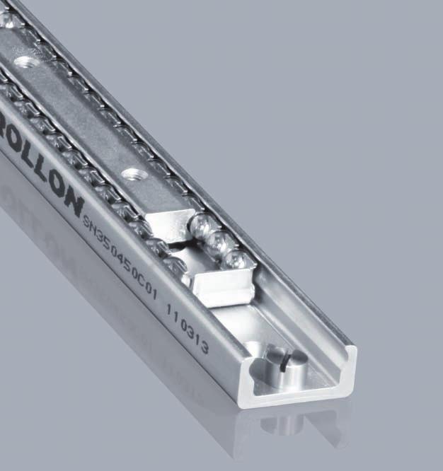
106 1 Product explanation Product explanation Easy Rail is a linear ball rail system (with caged ball bearings for the SN series or with recirculating ball bearings for the SNK series) with single slider or multiple sliders. Fig. 1 The Easy Rail series is a system of drawn steel linear rails with induction hardened raceways. The system consists of an external C profi le linear rail and one or more internal sliders with caged orrecirculating ball bearings. The most important characteristics: Guide rails and sliders of SN series made of cold-drawn bearing steel Ball cage made of steel for the SN series Balls made of hardened bearing steel Raceways of the guide rails and sliders are induction hardened (ground for the SNK series) Long service life With recirculating ball bearings for the SNK series Preferred areas of application of the Easy Rail product family: Transportation industry (e.g., exterior and interior rail and bus doors, seat adjustments, interior) Construction and machine technology (e.g., housings, protective covers) Medical technology (e.g., X-ray equipment, medical tables) Automotive technology Logistics (e.g., handling units) Packaging machines (e.g., beverage industry) Special machines SNK automation ER-2
107 Easy Rail SN linear bearing, version 1, with single slider This linear bearing consists of a guide rail and a slider that runs within the ball cage in the guide rail. High load capacities, compact cross-sections and simple and easy mounting characterize this series. Fig. 2 SN linear bearing, version 2, with multiple independent sliders Variant with several sliders, which each runs in its own ball cage, independent of each other, in the guide rail. Slider length and stroke for each slider can be different within one rail. Fig. 3 SN linear bearing, version 3, with multiple synchronized sliders Several sliders run in a common ball cage within the guide rails. The slider lengths can vary here as well and then form a total unit, which implements the corresponding stroke. Fig. 4 SNK series linear rails with recirculating ball bearings. The SNK series consists of a drawn steel C profi le rail with hardened and ground raceways and of an internal slider with a recirculating ball bearing system. This product is extremely compact and boasts high load rating and great sliding properties. Fig. 5 ER-3

108 2 Technical data Technical data Ball cage Rail Slider Fig. 6 Performance characteristics: Available sizes SN: 22, 28, 35, 43, 63 Sections available for the SNK series: 43 Inductive raceways hardened and ground for the SNK series Rails and sliders made of cold-drawn bearing steel Balls made of hardened bearing steel Max. operating speed 1.5 m/s (SNK) Temperature range: from -30 C to +170 C for the SN series from -20 to 70 for the SNK series Electrolytic zinc-plating as per ISO 2081; increased anticorrosive protection on request (see Chapter 4, Technical instructions, pg. 16 Anticorrosive protection) Linear accuracy 0.1 mm/m stroke 2 different types of preload for the SNK series Remarks: SN can only be horizontally mounted, high performance SNK can be horizontally and vertically mounted. External stops are recommended Fixing screws of property class 10.9 must be used for all linear bearings ER-4

109 Easy Rail Product dimensions SN Load capacities SN linear bearing, version 1, with single slider C 0rad M y K/2 Slider S a b b a Stroke H (L-S-K) K/2 M x C 0ax M z Rail L = (S+H+K) Fig. 7 To ensure that all fi xing holes of the rail are accessible, S must be < L/2 - K. To ensure proper smooth movement it is necessary that H 7S. Type Size Slider Load capacities and moments Length S a b No. of holes C 0rad [N] C 0ax [N] M x [Nm] M y [Nm] M z [Nm] SN Tab. 1 Rail Type Size Length L K SN Tab. 2 ER-5
110 3 Product dimensions Type Size Slider Load capacities and moments Length S a b No. of holes C 0rad [N] C 0ax [N] M x [Nm] M y [Nm] M z [Nm] SN Tab. 3 Rail Type Size Length L K SN Tab. 4 Type Size Slider Load capacities and moments Length S a b No. of holes C 0rad [N] C 0ax [N] M x [Nm] M y [Nm] M z [Nm] SN Tab. 5 Rail Type Size Length L K SN Tab. 6 ER-6
111 Easy Rail Type Size Slider Load capacities and moments Length S a b No. of holes C 0rad [N] C 0ax [N] M x [Nm] M y [Nm] M z [Nm] SN Tab. 7 Rail Type Size Length L K SN Tab. 8 Type Size Slider Load capacities and moments Length S a b No. of holes C 0rad [N] C 0ax [N] M x [Nm] M y [Nm] M z [Nm] SN Tab. 9 Rail Type Size Length L SN * For systems of versions 2 in size 63 with two independent sliders, the K dimension changes from 80 mm to 110 mm and for each additional slider by another 30 mm K* 80 Tab. 10 ER-7
112 3 Product dimensions Version 2 with multiple independent sliders K/2 Slider S Stroke H Stroke H Slider S K/2 a b b a a b b a Rail L = [2x (S+H) + K] For systems of versions 2 in size 63 with two independent sliders, the K dimension changes from 80 mm to 110 mm and for each additional slider by another 30 mm Fig. 8 Version 2 is a variant of version 1 with several independent sliders. The total load capacity is based on the number of sliders in the rail and on their lengths. The length and stroke of the individual sliders can be different. To ensure that all fi xing holes of the rail are accessible, S must be < L/2 - K. To ensure proper smooth movement it is necessary that H 7S. Version 3 with multiple synchronized sliders K/2 Slider S S Stroke H K/2 Slider S 1 2 a b b a a b b a Rail L = S +H+K Fig. 9 Version 3 is a variant of version 1 with several synchronized sliders. The total load capacity is based on the number of sliders in the rail. The length of the individual sliders can therefore vary. To ensure that all fi xing holes of the rail are accessible, S must be < L/2 - K. To ensure proper smooth movement it is necessary that H 7S. ER-8
113 Easy Rail SN Cross-section SN SN 63 A I A I E 1 J F E 2 V 1 B J F C 2 B G G 1 Fixing holes (V) for countersunk head screws according to DIN Fixing holes (C) for socket cap screws according to DIN Alternative fi xing with Torx screws in special design with low head (on request) Fig. 10 Type Size Cross-section Rail A B I J G E 1 E 2 [ ] V C F weight [kg/m] Slider weight [kg/m] SN M4 - M M5 - M M6 - M M8 - M x 45 - M8 M Tab. 11 ER-9
114 3 Product dimensions SNK - Load capacities C 0rad M y 40 M x C 0ax 80 M5 40 M z A 19 B A S T Fig.11 Type Size Slider Load capacities and moments Length S Length T A B N of holes C 0rad [N] C 0ax [N] M x [Nm] M y [Nm] M z [Nm] SNK Tab. 12 Rail Type Size Length L TSC/TSV Tab. 13 ER-10
115 Easy Rail SNK Cross-section SNK43/TSC 3,1 SNK43/TSV 0,3 90 A Ø 10,5 Ø 18 Ø 9 B C housing for special M8 TORX head screw housing for M8 countersunk hex head screw, DIN 7991 compliant Fig. 12 Type Size Cross-section Rail A B C weight [kg/m] Slider weight 110 [g] Slider weight 150 [g] TSC/TSV , Tab. 14 ER-11
116 4 Technical instructions Technical instructions Static load The maximum static loads of the SN series are defi ned using the slider length and are listed in the tables of the previous pages. These load capacities are valid for a loading point of forces and moments in the center of the slider (for off-center loading, see pg. 13). The load capacities are independent of the position of the slider inside the rails. During the static tests the radial load capacity, C 0rad, the axial load capacity, C 0ax, and moments M x, M y and M z indicate the maximum permissible values of the loads. Higher loads negatively affect the running properties and the mechanical strength. A safety factor, S 0, is used to check the static load, which takes into account the basic parameters of the application and is defi ned in more detail in the following table: Safety factor S 0 Neither shocks nor vibrations, smooth and low-frequency reverse, high assembly accuracy, no elastic deformations Normal installation conditions Shocks and vibrations, high-frequency reverse, signifi cant elastic deformation Tab. 15 The ratio of the actual load to maximum permissible load may be as large as the reciprocal of the accepted safety factor, S 0, at the most. P 0rad 1 P 0ax 1 M 1 1 M 2 1 M 3 1 C 0rad S 0 C 0ax S 0 M x S 0 M y S 0 M z S 0 Fig. 13 The formulas above apply for a single load case. If there are two or more of the described forces simultaneously, the following check must be made: P 0rad P 0ax M 1 M 2 M C 0rad C 0ax M x M y M z 1 S 0 P 0rad = effective radial load C 0rad = permissible radial load P 0ax = effective axial load C 0ax = permissible axial load M 1 = effective moment in the x-direction M x = permissible moment in the x-direction M 2 = effective moment in the y-direction M y = permissible moment in the y-direction M 3 = effective moment in the z-direction M z = permissible moment in the z-direction Fig. 14 ER-12
117 Easy Rail Off-center load P of the slider (SN series): For an off-center load of the slider, the different load distribution on the balls must be accounted for with a reduction of the load capacity C. As shown in the diagram at the right, this reduction of the distance, d, from the loading point is dependent on the slider center. The value, q, is the position factor, the distance, d, is expressed in fractions of slider length S. The permissible load, P, decreases as follows: P = q C 0rad for a radial load P = q C 0ax for an axial load Fig. 15 Fig. 17 For the static load and the service life calculation, P 0rad and P 0ax must be replaced by the equivalent values calculated as follows (see pg. 14, fi g. 16): P 0rad = P 0ax = P q P q if the external load, P, acts radially if the external load, P, acts axially Fig. 16 Fig. 18 ER-13
118 4 Technical instructions Service life The service life of a linear bearing depends on several factors, such as effective load, operating speed, installation precision, occurring impacts and vibrations, operating temperature, ambient conditions and lubrication. The service life is defi ned as the time span between initial operation and the fi rst fatigue or wear indications on the raceways. In practice, the end of the service life must be defi ned as the time of bearing decommissioning due to its destruction or extreme wear of a component. This is taken into account by an application coeffi cient (f i in the formula below), so the service life consists of: Series SN C L km = 100 ( 0rad 1 ) 3 W f i L km = calculated service life ( km ) C 0rad = load capacity ( N ) W = equivalent load ( N ) f i = application coeffi cient (see tab. 13) Series SNK Fig. 19 C f L Km = 100 ( c f h ) 3 P f i L km = theoretical service life ( km ) C = dynamic load capacity ( N ) P = effective equivalent load ( N ) f c f i f h = contact factor = application coeffi cient = stroke factor Fig. 20 Number of sliders f c Tab. 16 Application coefficient f i Neither impacts nor vibrations, smooth and low-frequency direction change, clean operating conditions, low speed ( <0.5 m/s) Slight vibrations, average speeds (between 0.5 and 0.7 m/s) and average direction change Impacts and vibrations, high-frequency direction change, high speeds ( >0.7 m/s), very dirty environment If the external load, P, is the same as the dynamic load capacity, C 0rad, (which of course must never be exceeded ), the service life at ideal operating conditions ( f i = 1) amounts to 100 km. Naturally, for a single load P, the following applies: W = P. If several external loads occur simultaneously, the equivalent load is calculated as follows: Tab. 13 P W = P rad + ( ax M + 1 M + 2 M + ) 3 C 0rad C 0ax M x M y M z Fig. 21 ER-14
119 G 1 Standard K 1 Tab. 18 Easy Rail Clearance and preload The linear ball bearings of the SN and SNK series are mounted as standard with no play. For more information, contactourtechnicalservice. Preload classes Increased clearance No clearance Increased preload * for higher preload, contact our technical offi ce Coefficient of friction With correct lubrication and installation on level and rigid surfaces and suffi cient parallelism for rail pairs, the friction value is less than or equal to This value can vary depending on the installation situation (see pg. ER-19, Instructions for use). Per la seria SNK il coeffi ciente di attrito é uguale o inferiore a 0,06. Linear accuracy With installation of the rails using all bolts on a perfectly plane support surface with the fi xing holes in a straight line, the linear accuracy of the sliders to an external reference results from the following equation: H // = (mm) 300 H = Stroke Fig. 22 Speed The linear bearings of the SN series can be used up to an operating speed of 0.8 m/s (31.5 in/s). With high-frequency direction changes and the resulting high accelerations, as well as with long ball cages, there is a risk of cage creep (see pg. ER-19, Instructions for use). The SNK series rails, on the other hand, reach a maximum speed of 1.5 m/s. There is no risk of cage displacement with SNK seriesrails. Temperature The SN series can be used in ambient temperatures from -30 C to +170 C (-22 F to +338 F ). The SNK series can be used at ambient temperatures between -20 C and + 70 C. A lithium lubricant for high operating temperatures is recommended for temperatures above +130 C (+266 F ). ER-15
120 4 Technical instructions Anticorrosive protection The SN series has a standard anticorrosive protection by electrolytic zinc-plating according to ISO If increased anticorrosive protection is required, the rails are available chemically nickel-plated and with stainless steel bearing balls. Numerous application-specifi c surface treatments are available upon request, e.g., as a nickel-plated design with FDA approval for use in the food industry. For more information please contact Application Technology. Lubrication SN Recommended lubrication intervals are heavily dependent upon the ambient conditions. Under normal conditions, lubrication is recommended after 100 km operational performance or after an operating period of 6 months. In critical application cases the interval should be shorter. Please clean the raceways carefully before lubrication. Raceways and spaces of the ball cage are lubricated with a lithium lubricant of average consistency (roller bearing lubricant). Different lubricants for special applications are available upon request. Example: Lubricant with FDA approval for use in the food industry. For more information please contact Application Technology. Lubrication SNK Lubrication when using N-sliders SNK43 The SNK43 sliders are fi tted with a self lubricating kit provided to periodically lubricate the slider. This provides a progressive release of lubricant (see tab. 36) on the raceway during operation of the slider. The expected service life is up to 2 million cycles, depending on the type of application. The zerk fi ttings (see fi g. 23) provide the lubrication. Lubricant Thickening agent Temperature range [ C] Dynamic viscosity [mpas] Mineral oil Lithium soap to +120 < 1000 Roller bearing lubricant Lithium soap -30 to Tab. 19 Grease applicator M6x1 DIN 3405 compliant Fig. 23 ER-16
121 Easy Rail Fixing screws L K The rails of the SN series in sizes 22 to 43 mm are fi xed with countersunk head screws according to DIN The SNK43 series rails are fastened with countersunk head screws according to DIN 7991 or with TorxR head screws (special design, see fi g. 24). S d D Fig. 24 Size Screw type d D L K S Tightening torque 63 M8 x 20 M8 x T40 34,7 SNK43 M8 x 16 M8 x 1, T40 22 Tab. 20 Tightening torques of the standard fixing screws to be used Property class Size Tightening torque [Nm] Tab. 21 Installation instructions Internal stops only fi tted on the SN series are used to stop the unloaded slider and the ball cage. Please use external stops as end stops for a loaded system. To achieve optimum running properties, high service life and rigidity, it is necessary to fi x the linear bearings with all accessible holes on a rigid and level surface. ER-17
122 4 Technical instructions Joined Rails If long guide rails are required, two or more rails can be joined to the desired length. When putting guide rails together, be sure that the register marks shown in fi g. 25 are positioned correctly. These are fabricated asymmetric for parallel application of joined guide rails, unless otherwise specifi ed. Two rails Comp. L Joint A Joint marks A Several rails Joint Comp. L Joint A1 A1 A2 A2 Joint marks Joint marks Joint Joint B1 Joint marks B1 B2 Joint marks B2 Fig. 25 General information The maximum available rail length in one piece is indicated in table 13 on page ER-10. Longer lengths are achieved by joining two or more rails (joined rails). Rollon then machines the rail ends at a right angle to the impact surfaces and marks them. Additional fi xing screws are included with the delivery, which ensure a problem-free transition of the slider over the joints, if the following installation procedures are followed. Two additional threaded holes are required in the load-bearing structure. The included end fi xing screws correspond to the installation screws for the rails for cylindrical counterbores. The alignment fi xture for aligning the rail joint can be ordered using the designation given in the table (tab. 22). A A L Fig. 26 Rail type A Threaded hole (load-bearing structure) Screw type L Alignment fixture TVC/TVS 11 M8 see pg. CR AT43 Tab. 22 ER-18
123 Easy Rail Instructions for use For linear bearings of the SN series, the sliders are guided through a ball cage inside the rails. When the sliders run their course relative to the rails, the ball cage moves along for half the slider stroke. The stroke ends as soon as the slider reaches the end of the cage. Normally the cage moves synchronously to the balls at half the speed of the slider. Any occurring cage slip affects the synchronous movement of the ball cage negatively, causing it to reach the internal stops prematurely (cage creep). This reduces the stroke. However, the stroke value can be normalized at any time by moving the slider to the stop in the stopped cage. This moving of the slider relative to the cage will have increased resistance, which is dependent on the working load. The causes of cage creep can be installation accuracy, dynamics, and load changes. The effects can be minimized by observing the following advice: - The stroke should always remain constant and come as close as possible to the nominal stroke of the linear bearing. - For applications with various strokes, make sure that the drive is suffi ciently dimensioned to guarantee a movement of the slider relative to the cage. A coeffi cient of friction of 0.1 should be calculated for this. - Another possibility is to include a maximum stroke without load in the working cycle in order to resynchronize the slider and ball cage. Parallelism errors or inaccuracies in the installation or in the mounting surfaces of mounted pairs can infl uence the cage creep. Series SN linear bearings should only be used for horizontal movement. SNK: Always handle the slider out of the rail by its plastic retainer to prevent ball bearings from escaping. ER-19
124 5 Standard configurations SN Standard configurations Size 22 Ordering description Slider Stroke Rail SN SN SN SN SN SN SN SN SN SN SN SN SN SN SN SN SN SN SN SN SN SN SN SN SN SN SN SN SN SN SN SN SN SN SN SN SN SN SN SN Tab. 17 Size 28 Ordering description Slider Stroke Rail SN SN SN SN SN SN SN SN SN SN SN SN SN SN SN SN SN SN SN SN SN SN SN SN SN SN SN SN SN SN SN SN SN SN SN SN SN SN SN SN SN SN SN SN SN SN SN SN SN SN SN SN SN Tab. 18 Size 35 Ordering description Slider Stroke Rail SN SN SN SN SN SN SN SN SN SN SN SN SN SN SN SN SN SN SN SN SN SN SN SN SN SN SN SN SN SN SN SN SN SN SN SN SN SN SN SN SN SN SN SN SN SN SN SN SN SN SN SN SN SN SN Tab. 19 ER-20
125 Easy Rail Size 43 Ordering description Slider Stroke Rail SN SN SN SN SN SN SN SN SN SN SN SN SN SN SN SN SN SN SN SN SN SN SN SN SN SN SN SN SN SN SN SN SN SN SN SN SN SN SN SN SN SN SN SN SN SN SN SN SN SN SN SN SN SN SN SN SN SN SN SN SN Tab. 20 Size 63 Ordering description Slider Stroke Rail SN SN SN SN SN SN SN SN SN SN SN SN SN SN SN SN SN SN SN SN SN SN SN SN SN SN SN SN SN SN SN SN SN SN SN SN SN SN SN SN SN SN SN SN SN SN SN SN SN SN SN SN SN Tab. 21 The most commonly used standard confi gurations are shown in the tables. Other deviating confi gurations and customer-specifi c adaptations are possible. For more information please contact Application Technology. ER-21
126 Fold out ordering key Fold out ordering key To make this product catalog as simple as possible for you to use, we have included the following easy-to-read chart. Your advantages: Description and ordering designations easy to read at one glance Simplifi ed selection of the correct product Links to detailed descriptions in the catalog ER-22
127 Easy Rail Ordering key SN Version 1 with a slider SN K1 NIC Expanded surface protection see pg. ER-16, Anticorrosive protection Clearance and preload, if deviating from standard see pg. ER-15, tab. 14 Product type Size Rail length see pg. ER-5, tab. 2, 4, 6, 8, 10 Stroke see pg. ER-5, fi g. 7, tab. 1 to 10 Slider length see pg. ER-5, tab. 1, 3, 5, 7, 9 see pg. ER-4, Performance characteristics Ordering example 1: SN Ordering example 2: SN K1-NIC Notes on ordering: Rail and slider lengths, as well as strokes, are always stated with 4 digits. Please use zeroes to fi ll in for lengths with less than 4 digits SN version 2 with multiple independent sliders SN G1 NIC Expanded surface protection see pg. ER-16, Anticorrosive protection Clearance and preload, if deviating from standard see pg. ER-15, tab. 18 Product type Size Rail length see pg. ER-5, tab. 2, 4, 6, 8, 10 Stroke of the individual sliders see pg. ER-5, fi g. 7, tab. 1 to 10 Slider length see pg. ER-5, tab. 1, 3, 5, 7, 9 Number of sliders see pg. ER-4, Performance characteristics Ordering example 1: SN43-2x Ordering example 2: SN43-2x G1-NIC If the individual slider lengths and/or strokes are different, please order according to ordering example 3. Ordering example 3: SN28-1x /1x Notes on ordering: Rail and slider lengths, as well as strokes, are always stated with 4 digits. Please use zeroes to fi ll in for lengths with less than 4 digits ER-23
128 Ordering key SN Version 3 with multiple synchronized sliders SN ( ) K1 NIC Expanded surface protection see pg. ER-16, Anticorrosive protection Clearance and preload, if deviating from standard see pg. ER-15, tab. 18 Product type Size Rail length see pg. ER-5, tab. 2, 4, 6, 8, 10 Stroke see pg. ER-5, fi g. 7, tab. 1 to 10 Individual length of slider see pg. ER-5, tab. 1, 3, 5, 7, 9 Apparent length, S of the slider see pg. ER-8, fi g. 9 see pg. ER-4 Performance characteristics Ordering example 1: SN ( ) Ordering example 2: SN ( ) K1-NI C Notes on ordering: Rail and slider lengths, as well as strokes, are always stated with 4 digits. Please use zeroes to fi ll in for lengths with less than 4 digits Serie SNK SNK TSC NIC Product type Size For surface protection different from standard ISO 2081 see see pg. ER-16 Tipo di guida see pg. ER-10 e ER-11 Rail length see pg. ER-10 tab 13 Number of sliders for each rail Slider length see pg. ER-10. see pg. ER-4 Performance characteristics Ordering example: TSC-02320/1/SNK Z-NIC Rail kit: 1x2000+1x320 (only for joined rails) Drilling pattern: 40-40x80-40//40-15x80-40 (always state the drilling pattern separately) Note for ordering: Rail lengths are always shown with fi ve fi gures, and slider lengths are indicated with three fi gures preceded by zeros ER-24
129 Easy Rail Notes ER-25
130
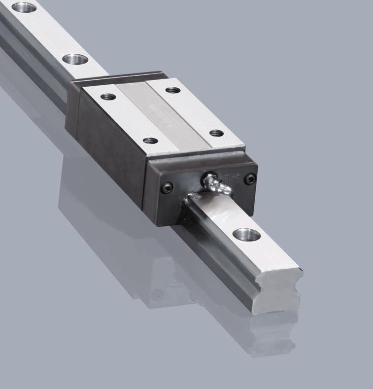
131 Mono Rail


132 1 Product explanation Product explanation Mono Rails are profile rails for the highest degree of precision Fig. 1 The running grooves are ground in semicircular profi le and have a contact angle of 45 in X-arrangement so that the same load capacity is guaranteed in all principle directions. Use of large steel balls enables high load and moment capacities. All carriages in size 55 are equipped with ball chains. The most important characteristics: X-arrangement with 2-point contact of the raceways Uniform loading capacity in all main directions High ability for self-regulating Small differential slip in comparison to 4-point contact Very quiet running and low operating noise Low maintenance due to advanced lubrication chamber Small displacement force in preload compared to 4-point contact Mono Rail profi le rails meet the market standard and can replace linear rails of the same design from other manufacturers while maintaining the main dimensions Miniature Mono Rails available in a standard or large version Preferred areas of application: Construction and machine technology ( safety doors, feeding ) Packaging machines Special purpose machinery Logistics ( e.g., handling units ) Medical technology ( e.g., X-ray equipment, hospital gurneys ) Semiconductors and electronics industry MR-2
133 Mono Rail MRS / MRT Standard carriage with fl ange in two different heights. MRT is the lower version. Fig. 2 MRS...W / MRZ...W / MRT...W Carriage without fl ange, also called block. Available in three different heights. MRT is the lower version; MRZ is the intermediate size. Fig.3 MRS...L Carriage in long version for holding larger loads. MRS...L is the version with fl ange. Fig. 4 MRS...LW / MRT...LW Carriage in long version without fl ange. Available in two different heights. MRT is the lower version. Fig. 5 MRT...S Carriage with fl ange in short version for lower loads with equally high precision. Fig.6 MR-3


134 1 Product explanation MRT...SW Carriage without fl ange in short version for lower loads with equally high precision. Fig. 7 MRR...F Guide rail MRR...F for bolting from below with threaded holes. Design with smooth surface without bevels. Fig. 8 Standard width Compact technology and high performance in its smallest structural shape. Fig. 9 Large width Wide miniature profi le rails, with a compact size, allow the acceptance of higher forces and moments. Especially suited for single rail applications. Fig. 10 Integrated redirection During the carriage movements, the plastic end caps are subjected to permanent shocks caused by the continuous change of direction of movement. These shock loads have a critical infl uence on the running properties and speed. Automation and production demands of modern industry call for high operating speeds. The integrated ball redirection, i.e., the direct connection of ball redirection and body, creates an optimum solution for the miniature profi le rails. Fig. 11 MR-4

135 Mono Rail Technical data Rail End seal Self-lubricating element Redirection Side seal Slider body Lubrication nipple Fig. 12 Performance characteristics: Mono Rail available sections: 15, 20, 25, 30, 35, 45, 55 Standard version Miniature Mono Rail available sections: 7, 9, 12, 15 Large version Miniature Mono Rail available sections: 9, 12, 15 Max. operating speed: 3.5 m/s ( in/s ) ( depending on application ) Max. operating temperature: +80 C (+176 F ) ( depending on application ) Available rail lengths up to approx. 4,000 mm ( in ) for Mono Rail ( see Ordering key, Table 31) Four preload classes for Mono Rail: G1, K0, K1, K2 Three precision classes: N, H, P Three preload classes for the Miniature Mono Rails: V0, VS, V1 Lengths for single rails are available up to 1,000mm (39.37 in) for theminiature Mono Rail Remarks: Combining rails is possible ( joining ) The fi xing holes on the carriages with fl ange can also be used as through holes for fastening from below. Here, the reduction in size of the screw diameter must be observed Various surface coatings on request, e.g. black coating, hard chrome plating, nickel plating Manual and pneumatic clamping elements available as accessories. Depending on the height of the carriage, additional adapter plates must be used Dimensions H 2 and L of the carriage change when using metal defl ectors and other seals. Refer to Sec. 4 Accessories, pg. MR-16f The carriages in size 55 are equipped with ball chains Primary lubricated systems have an increased displacement resistance MR-5
136 2 Technical data Mono Rail load capacities C 0ax M x M z C 0rad M y Fig. 13 Type Load capacities [N] Static moments [Nm] Type Load capacities [N] Static moments [Nm] dyn. C stat. C 0rad M x M y M z stat. C 0ax dyn. C stat. C 0rad M x M y M z stat. C 0ax MRS15 MRS15W MRT15W MRS30 MRS30W MRT30W MRT15SW MRT30SW MRS20 MRS20W MRT20W MRS30L MRS30LW MRT30LW MRT20SW MRS20L MRS20LW MRS25 MRT25 MRS25W MRT25W MRZ25W MRS35 MRS35W MRT35W MRT35SW MRS35L MRS35LW MRT35LW MRT25S MRT25SW MRS45 MRS45W MRT45W MRS25L MRS25LW MRT25LW MRS45L MRS45LW MRT45LW Tab. 1 MCS55 MCS55W MCT55W MCS55L MCS55LW MCT55LW Tab. 2 MR-6
137 Mono Rail Miniature Mono Rail load capacities Standard width M y M x C 0 M z C 0 C 0 Fig. 14 Type Load capacities [N] Static moments [Nm] dyn. C 100 stat. C 0 M x M y M z MR07MN MR09MN MR12MN MR15MN Tab. 3 Large width M y M x C 0 M z C 0 C 0 Fig. 15 Type Load capacities [N] Static moments [Nm] dyn. C 100 stat. C 0 M x M y M z MR09WN MR12WN MR15WN Tab. 4 MR-7
138 3 Product dimensions Product dimensions MRS series carriage with flange L 2 L* L 1 P 1 W P 2 S D H 1 H H 2 * g 1 g 2 M (4 Threads) P (Hole pitch) d L 3 W 2 W 1 T (Lubrication nipple) * Dimensions H2 and L change when using metal defl ectors and other seals ( see pg. MR-12, tab. 12 ) Fig. 16 Type System Slider MRS Weight [kg] Rail MRR Weight [kg/m] H W W 2 H 2 L P 2 P 1 M g 2 L 1 L 2 T S W 1 H 1 P d D g 1 L 3 * MRS , M , MRS M6 9 7 MRS20L MRS M8 7.8 MRS25L M6 x 1 MRS MRS30L M10 MRS , MRS35L MRS M M8 x MRS45L * Only applies when using max. rail lengths ( see Ordering key, tab. 31) Tab. 5 Type System Slider MCS Weight [kg] Rail MCR Weight [kg/m] H W W 2 H 2 L P 2 P 1 M g 2 L 1 L 2 T S W 1 H 1 P d D g 1 L 3 * MCS ,5 12, M M8 x 1 20 MCS55L * Only applies when using max. rail lengths ( see Ordering key) Tab. 6 MR-8
139 Mono Rail MRS series carriage without flange L 2 L* L 1 P 1 W P 2 S D H 1 H 2 * H g 2 g 1 M (4 Threads) P (Hole pitch) d L 3 W 2 W 1 T (Lubrication nipple) * Dimensions H2 and L change when using metal defl ectors and other seals ( see pg. MR-12, tab. 12 ) Fig. 17 Type System Slider MRS Weight [kg] Rail MRR Weight [kg/m] H W W 2 H 2 L P 2 P 1 M g 2 L 1 L 2 T S W 1 H 1 P d D g 1 L 3 * MRS15W , M , MRS20W M5 8 7 MRS20LW MRS25W M MRS25LW M6 x 1 MRS30W MRS30LW M MRS35W , MRS35LW MRS45W M M8 x MRS45LW * Only applies when using max. rail lengths ( see Ordering key, tab. 31) Tab. 7 Type System Slider MCS Weight [kg] Rail MCR Weight [kg/m] H W W 2 H 2 L P 2 P 1 M g 2 L 1 L 2 T S W 1 H 1 P d D g 1 L 3 * MCS55W M M8 x 1 30 MCS55LW * Only applies when using max. rail lengths ( see Ordering key) Tab. 8 MR-9
140 3 Product dimensions MRT series carriage with flange L 2 L* L 1 L 2 L* L 1 W P 1 = = P 2 D H 1 H g 1 S g 2 H 2 * M (4 Threads) M (2 Threads) d W 2 W 1 P (Hole pitch) L 3 T (Lubrication nipple) * Dimensions H 2 and L change when using metal defl ectors and other seals ( see pg. MR-12, tab. 12 ) Fig. 18 Type System Slider MRT Weight [kg] Rail MRR Weight [kg/m] H W W 2 H 2 L P 2 P 1 M g 2 L 1 L 2 T S W 1 H 1 P d D g 1 L 3 * MRT M M6 x MRT25S * Only applies when using max. rail lengths ( see Ordering key, tab. 31 ) , Tab. 9 MR-10
141 Mono Rail MRT series carriage without flange L 2 L* L 1 P 1 L 2 L* L 1 = = W P 2 D g 2 H 1 H H 2 * g 1 S M (4 Threads) M (2 Threads) d W 2 W 1 P (Hole pitch) L 3 T (Lubrication nipple) * Dimensions H 2 and L change when using metal defl ectors and other seals ( see pg. MR-12, tab. 12 ) Fig. 19 Type System Slider MRT Weight [kg] Rail MRR Weight [kg/m] H W W 2 H 2 L P 2 P 1 M g 2 L 1 L 2 T S W 1 H 1 P d D g 1 L 3 * MRT15W M MRT15SW MRT20W M5 7 5 MRT20SW MRT25W MRT25SW M MRT25LW MRT30W M6 x MRT30SW MRT30LW M MRT35W MRT35SW MRT35LW MRT45W M M8 x MRT45LW * Only applies when using max. rail lengths ( see Ordering key, tab. 31 ) Tab. 10 Type System Slider MCT Weight [kg] Rail MCR Weight [kg/m] H W W 2 H 2 L P 2 P 1 M g 2 L 1 L 2 T S W 1 H 1 P d D g 1 L 3 * MCT55W M M8 x 1 18 MCT55LW * Only applies when using max. rail lengths ( see Ordering key ) Tab. 11 MR-11
142 3 Product dimensions MRZ series carriage without flange L 2 L* L 1 P 1 W P 2 D g 2 H 1 H H 2 * S g 1 M (4 Threads) d W 2 W 1 P (Hole pitch) L 3 T (Lubrication nipple) * Dimensions H2 and L change when using metal defl ectors and other seals ( see pg. MR-12, tab. 12 ) Fig. 20 Type System Slider MRZ Weight [kg] Rail MRR Weight [kg/m] H W W 2 H 2 L P 2 P 1 M g 2 L 1 L 2 T S W 1 H 1 P d D g 1 L 3 * MRZ25W M M6x1 7.8 MRZ25LW * Only applies when using max. rail lengths ( see Ordering key, tab. 31 ) Tab. 12 MR-12
143 Mono Rail MRR...F series rails mounted from below g 1 H 1 L 3 P (Hole pitch) F (Threads) W 1 Fig. 21 Rail type W 1 H 1 L 3 * P F g 1 MRR15...F M5 8 MRR20...F M6 MRR25...F MRR30...F M8 MRR35...F MRR45...F M12 24 Tab. 13 * Only applies when using max. rail lengths ( see Ordering key ) MR-13
144 3 Product dimensions Miniature Mono Rail standard width Fig. 22 Type System H W W 2 H 2 MR07MN MR09MN MR12MN MR15MN Tab. 14 Type Slider Rail L P 2 P 1 M g 2 L 1 T S Ø Weight [kg] W 1 H 1 P d D g 1 Weight [kg/m] MR07MN M MR09MN M MR12MN M MR15MN M Tab. 15 MR-14
145 Mono Rail Miniature Mono Rail large width MR15W Fig. 23 Type System H W W 2 H 2 MR09WN MR12WN MR15WN Tab. 16 Type Slider Rail L P 2 P 1 M g 2 L 1 T S Ø Weight [kg] W 1 H 1 P P 3 d D g 1 Weight [kg/m] MR09WN M MR12WN M MR15WN M Tab. 17 MR-15
146 4 Accessories Accessories Safety equipment and covers End seal Carriages of Mono Rail profi le rails are equipped with end seals for contamination protection as standard. End seal Fig. 24 Side seal To prevent permeation of foreign matter from below, the carriages for this area are offered with appropriate seals. No side seals are available for carriages in long or short version (...S / S...W and...l / L...W ). Side seal Fig. 25 Double seal To improve the protection from contamination at higher loads the carriage can be provided with double end seals. End seal Spacer plate End seal Fig. 26 Metal deflector (non-contacting) Metal cuttings or coarse contamination can damage the end seals of the carriage. Metal defl ector covers protect seal lips against damage. End seal Metal deflector Fig. 27 MR-16
147 Mono Rail Seal variants: A: Carriage with end and side seal C: Carriage with end and side seals and metal defl ector D: Carriage with double end seal and side seal E: Carriage with double end seal and side seal and metal defl ector Changes of fl oor clearance and length changes of the carriages when using the corresponding seal variants Seal variant A, C, D, E, A C D E Slider type 1 Size Changed dimension H 2 * MRS MRS...W MRT MRT...W Changed length L* MCS MCS...W MCT MCT...W MRS...L MRS...LW MRT...LW MCS...L MCS...LW MCT...LW MRT...S MRT...SW Tab No side seals are available for carriages in long or short version (...S / S...W and...l / L...W ) * For comparison see Chapter 3 Product dimensions, pg. MR-8ff MR-17
148 4 Accessories Metal cover strip A rail cover strip made of corrosion resistant steel is available to improve the seal after guide rail installation. The metal cover strip is 0.3 mm wide and can have a maximum length of 50 m. Cover strip Handle 30 Size Width Rail end clamp Fig Tab. 19 Flush cap Metal debris and other foreign substance can collect in the fi xing holes of the rails and thus end up the carriage. To prevent penetration of contamination in the carriage, the fi xing holes should be capped with perforated caps fl ush with the rail surface. Flush caps are made of wear and oil resistant synthetic resin. Various sizes of perforated caps for the counter sunk holes for hexagon socket bolts M3 to M22 are included as standard in the scope of supply. Flush caps are driven in fl ush with the rail surface with light hammer taps using a fl at piece of metal (see fi g. 29). Plastic hammer Flat piece of metal Fig. 29 MR-18
149 Mono Rail Clamping elements Mono Rail profi le rails can be secured with manual or pneumatic clamping elements. Areas of application are: Table cross beams and sliding beds Width adjustment, stops Positioning of optical equipment and measuring tables Pneumatic clamp elements MK / MKS The patented wedge slide gear puts into effect high holding forces. The pressurised medium moves the wedge slide gear in the longitudinal direction. Contact profi les press with high force on the free surfaces of the profi le rail by the resulting cross movement. MK is an element that closes with pneumatic pressure. The custom design MKS closes with spring energy storage and is opened via air impingement. Manual clamp elements HK The HK series is a manually activated clamping element. Contact profi les press synchronously on the free surfaces of the profi le rail by using the freely adjustable clamping lever. The fl oating mounted contact profi les guarantee symmetrical introduction of force on the guide rail. Special characteristics of the clamping elements HK: Simple and safe design Floating contact profi le Precise positioning Holding force up to 2,000 N Special characteristics of clamp elements MK / MKS: Short shape High clamp forces Precise positioning High axial and horizontal rigidity Areas of application of MK: Positioning axes Setting vertical axes Positioning lifting gear Clamping machine tables Variants: An additional adapter plate must be used depending on the height of the carriage ( see pg. MR-22, tab. 22 ). Activation: Standard with hand lever, further activation options, e.g. using DIN 912 screw, possible on request. Variants: An additional adapter plate must be used depending on the height of the carriage ( see pg. MR-22, tab. 23 ). Connection options: The basic MK / MKS series versions are equipped with air connections on both sides, i.e. the factory default settings air connections and the ventilation fi lter can be exchanged to the opposite side surfaces. Custom design MKS opens with impingement of an air pressure of > 5.5 bar. Areas of application of MKS: Clamping with drop in pressure (Normally Open) Clamping without power required (Normally Closed) MR-19
150 4 Accessories Manual clamp HK Adapter plate P 2 M (4 Threads) D* H W H 2 g 1 H 1 H 3 L P 1 W 1 W 2 * Changed dimensions when using the adapter plate, see pg. MR-22, tab. 22 Fig. 30 Type Size Holding force Tightening torque Dimensions M [N] [Nm] H H 1 H 2 H 3 W W 1 W 2 L P 1 P 2 g 1 HK1501A M4 HK2006A HK2006A M5 HK2501A HK2514A M6 HK3001A HK3501A M HK4501A M10 HK5501A M14 Tab. 20 MR-20
151 Mono Rail Pneumatic clamp MK / MKS Adapter plate P 2 M (4 Threads) W W 1 H 2 P 3 D* H B 4 L 1 P 1 L g 1 W 2 Q * Changed dimensions when using the adapter plate, see pg. MR-22, tab. 23 Fig. 31 Type Size MK holding force MK / MKS 1501A MK / MKS 2001A MK / MKS 2501A [N] MKS holding force [N] Dimensions H H 2 W W 1 W 2 B 4 L 1 * L P 1 P 2 P 3 Q [ ] M M M6 g 1 M MK / MKS 3001A MK / MKS 3501A M8 MK / MKS 4501A MK / MKS 5501A * Only for model MKS M10 Tab. 21 MR-21
152 4 Accessories Adapter plate For HK clamps Clamp Size Slider type Adapter plate D HK1501A 15 HK2006A 20 HK2514A 25 HK2501A HK3001A 30 HK3501A 35 HK4501A 45 On request 55 HK5501A MRS, MRT...W, MRT...SW - 24 MRS...W PHK MRT...S, MRT...W, MRT...SW - 28 MRS, MRS...L, MRS...W, MRS...LW - 30 MRT, MRT...S, MRT...W, MRT...SW, MRT...LW - 33 MRS, MRS...L, - 36 MRS...W, MRS...LW PHK MRS, MRS...L, MRT...W, MRT...SW, MRT...LW - 42 MRS...W, MRS...LW PHK MRS, MRS...L, MRT...W, MRT...SW, MRT...LW - 48 MRS...W, MRS...LW PMK MRS, MRS...L, MRT...W, MRT...LW - 60 MRS...W, MRS...LW PHK MRT...W, MRT...LW - 68 MRS, MRS...L - 70 MRS...W, MRS...LW PHK Tab. 22 For MK / MKS clamps Clamp Size Slider type Adapter plate D MK / MKS 1501A MK / MKS 2001A On request MK / MKS 2501A MK / MKS 3001A MK / MKS 3501A MK / MKS 4501A On request MK / MKS 5501A MR MRS, MRT...W, MRT...SW - 24 MRS...W PMK MRT...S, MRT...W, MRT...SW - 28 MRS, MRS...L, MRS...W, MRS...LW PMK MRT, MRT...S, MRT...W, MRT...SW, MRT...LW - 33 MRS, MRS...L, MRZ - 36 MRS...W, MRS...LW PMK MRS, MRS...L, MRT...W, MRT...SW, MRT...LW - 42 MRS...W, MRS...LW PMK MRS, MRS...L, MRT...W, MRT...SW, MRT...LW - 48 MRS...W, MRS...LW PMK MRS, MRS...L, MRT...W, MRT...LW - 60 MRS...W, MRS...LW PMK MRT...W, MRT...LW - 68 MRS, MRS...L - 70 MRS...W, MRS...LW PMK Tab. 23
153 Mono Rail Technical instructions Mono Rail precision Precision means the guide accuracy or the maximal deviation of the carriage based on the side and support surfaces during the movement along the rails. C D C D H H A W B A W B Fig. 32 Precision class Height tolerance H Side tolerance W Guide accuracy of raceway C based on surface A Normal [N] High [H] Precise [P] ± 0.1 ± to ΔC see graph in fig. 33 Guide accuracy of raceway D based on surface B ΔD see graph in fig. 33 Tab. 24 Δ C (μm) Δ D (μm) Normal (N) Norm Hoch High (H) Präz Precise (P) Schienenlänge Rail length (mm) (mm) Fig. 33 MR-23

154 5 Technical instructions Miniature Mono Rail precision There are three precision classes to choose from for the Mono Rail Miniature profi le rails: Classes P, H, and N are manufactured. P H P W2 Fig. 34 Precision classes Precision P [μm] High H [μm] Normal N [μm] H Tolerance of height H ± 10 ± 20 ± 40 ΔH Permissible height difference of different carriages at the same position on the rail W 2 Tolerance of width W 2 ± 15 ± 25 ± 40 ΔW 2 Permissible width difference of different carriages at the same position on the rail Tab. 25 Running accuracy Running accuracy (parallelism) μm mm Length of guide rail Fig. 35 MR-24
155 Mono Rail Mono Rail Radial clearance / preload Radial clearance describes the value for the radial movement of the carriage at a constant vertical load, while the carriage moves in longitudinal direction. Fig. 36 Preload is defi ned as an effective load on the rolling element in the interior of the carriage in order to remove an existing clearance or to increase the rigidity. The Mono Rail profi le rails are available in the four different preload classes G1, K0, K1 and K2 ( see tab. 26 ). The preload infl uences the rigidity, precision and torque resistance and also affects the service life and displacement force. The radial clearance for the respective preload classes are listed in table 20. Degree of preload Preload class Preload With clearance G1 0 No clearance K0 0 Small preload K1 0,02 x C* Average preload K2 0,05 x C* * C is the dynamic load capacity, see pg. MR-9, tab. 1f Tab. 26 Size Radial clearance of the preload classes [μm] G1 K0 K1 K2 Impact free movement, compensation of assembly tolerances Impact free and easy movement Small moments, one rail application, low vibrations Average vibrations and moments, light impacts to to to to to to to to to to to to to to to to to to to to to to to to to to to to -29 Tab. 27 MR-25
156 5 Technical instructions Miniature Mono Rail Preload The Mono Rail Miniature profi le rails are available in the three different preload classes V 0, V S and V 1 (see table 28). The preload infl uences the rigidity, precision and torque resistance and also affects the product service life and displacement force. Type Preload classes Small clearance Very quiet running Standard Very quiet and precise running Small preload High rigidity, vibration reduced, high precision, good load balance V 0 [μm] V S [μm] V 1 [μm] MR07 +4 to to 0 0 to -3 MR09 +4 to to 0 0 to -4 MR12 +5 to to 0 0 to -5 MR15 +6 to to 0 0 to -6 Tab. 28 MR-26
157 Mono Rail Anticorrosive protection There are numerous application-specifi c surface treatments available for profi le rails of the Mono Rail product family, for example, black coating ( X ), hard chrome plating ( XC ) or nickel plating ( NIC ), also with FDA-approval for use in the food industry. For more information please contact Application Technology. All linear rails of the Miniature Mono Rail series are made of stain less steel. Mono Rail lubrication Profi le rails must generally be lubricated before commissioning. They can be lubricated with oil or grease. The correct lubricant selection has a large infl uence on the service life and the function of the profi le rail, insuffi cient lubrication and tribocorrosion can ultimately lead to total failure. As well as reducing friction and wear, lubricants also serve as sealant, noise damper and corrosion protection for the linear guide. Different lubricants for special applications are available upon request. Example: Lubricant with FDA approval for use in the food industry. For more information please contact Application Technology. Important instructions for lubrication Mono Rail profi le rails must be lubricated for operation. The carriage must be moved back and forth during lubrication. The lubricant is inserted through a lubrication nipple. There should be a thin fi lm of lubricant on the rail surface at all times. Please inform us in advance if the guides are to be used in acid or base containing environments or in clean rooms. Primary lubricated systems have an increased displacement resistance. Please contact Application Technology if the oil lubrication is used for vertical use. If the stroke is < 2 or > 15 times the carriage length, the lubrication intervals should be shortened. Grease lubrication We recommend the use of a lithium emulsifi ed lubricant NLGI Class 2 for lubrication. Oil lubrication We recommend a synthetic oil for operating temperatures between 0 C and +70 C. For application-specifi c custom lubrication, please contact Application Technology. Relubrication Relubrication of the system must be done before the lubricant used is dirty or shows discolouration. Relubrication is performed at operating temperature. The carriage must be moved back and forth during relubrication. If the stroke is < 2 or > 15 times the carriage length, the lubrication intervals should be more often. Lubrication intervals Operating speed, stroke length and ambient conditions infl uence the selection of time between lubrication intervals. Establishing a safe lubrication interval is based exclusively on the experienced practiced values determined on site. However, a lubrication interval should not be longer than one year in any case. MR-27

158 5 Technical instructions Miniature Mono Rail lubrication Function The contact points between ball and track are separated from each other by a microscopically thin oil fi lm. The lubrication effects: Reduction of friction Reduction of wear Corrosion protection Better thermal distribution and therefore increased of service life Fig. 37 Important instructions for lubrication Mono Rail Miniature profi le rails must be lubricated for operation. The carriage must be moved back and forth during lubrication. The lubricant can also be applied to the tracks. The lubricant can be injected into the lubrication holes on both sides of the carriage. There should be a thin fi lm of lubricant on the rail surface at all times. Please inform us in advance if the guides are to be used in acid or base containing environments or in clean rooms. Please contact the sales department if the oil lubrication should be used for vertical use of the guide. If the stroke is < 2 or > 15 times the carriage length, the lubrication intervals should be more often. Type First lubrication [cm 3 ] MR07MN 0.12 MR09MN 0.23 MR12MN 0.41 MR15MN 0.78 Tab. 29 Type First lubrication [cm 3 ] MR09WN 0.30 MR12WN 0.52 MR15WN 0.87 Tab. 30 MR-28
159 Mono Rail Grease lubrication When using grease lubrication, we recommend synthetic-oil based lithium grease with a viscosity according to ISO VG 32 to ISO VG 100. Oil lubrication We recommend CLP or CGLP synthetic oil conforming to DIN or HLP to DIN and a viscosity range conforming to ISO VG 32 to ISO VG 100 for operating temperatures between 0 C and +70 C. We recommend a viscosity according to ISO VG 10 for use at low temperatures. For application-specifi c special lubrication please contact the Rollon Application engineering department. ISO VG 10 = mm2 Viscosity of 10 s at 40 C mm 2 ISO VG 32 = Viscosity of 32 s at 40 C mm ISO VG 100 = Viscosity of s at 40 C Lubrication intervals Operating speed, stroke length and ambient conditions infl uence the selection of time between lubrication intervals. Establishing a safe lubrication interval is based exclusively on the experienced practiced values determined on site. However, a lubrication interval should not be longer than one year in any case. Relubrication Relubrication of the system must be done before the lubricant used is dirty or shows discolouration. An application of approx. 50 % of the quantity used for fi rst lubrication is suffi cient for relubrication ( see tab. 31). Relubrication is performed at operating temperature. During relubrication, the carriage should be moved back and forth. If the stroke is < 2 or > 15 times the carriage length, the lubrication intervals should be more often. Fig. 38 Initial lubrication and relubrication Self-lubricating The carriages of the following sizes have a self-lubrication element to extend lubrication intervals. Not self-lubricating The carriages of sizes 35 and 45 are not self-lubricating due to the design. Size Initial lubrication grease Relubrication Initial lubrication oil Size Initial lubrication grease Relubrication Initial lubrication oil [cm 3 ] [cm 3 ] [cm 3 ] [cm 3 ] [cm 3 ] [cm 3 ] Tab. 31 The given lubrication quantities apply to preload K1 and speeds 1 m/s Tab. 32 The given lubrication quantities apply to preload K1 and speeds 1 m/s MR-29
160 5 Technical instructions Mono Rail lubrication nipple The following lubrication nipples are part of the standard delivery: NLA01 Ø 3 x 5 Lubrication nipple Size NLA ,3 NLB NLB02 16,6 M6 x 6 NLB Tab. 33 9,8 Other lubrication nipples, such as lubrication adapters with hose inlet or with quick-coupling, are available on request. Please observe that the thread lengths ( see fi g. 39 ) can be changed when using additional defl ectors and end seals. For more information please contact Application Technology. NLB04 16,6 M8 x 6 9,8 Fig. 39 MR-30
161 Mono Rail Friction / displacement resistance Mono Rail profi le rails have a low friction characteristic and thus low displacement resistance. The low start-up friction (breakaway force) is almost identical to the moving friction (running resistance). The displacement resistance is dependent upon several factors: Friction of the sealing system Friction of the balls with each other Friction between balls and redirection Rolling resistance of the balls in the running grooves Resistance of lubricant in the carriage Resistance by contamination in the lubricant Preload for increase of rigidity Moment load Resistance of the seals Type f [N] MRS MRS MRS MRS MRS Coefficient of friction (μ) MRS MCS Tab Loading ratio: (P/C) P: Loading C: Dynamic load capacities 0.2 Fig. 40 Displacement resistance The following formula is used for general approximate calculation of the displacement resistance. Please note that the level of preload or the viscosity of the lubricant used can also infl uence the displacement resistance. F m = Displacement resistance ( N ) F m = μ F + f F = Load ( N ) μ = Coeffi cient of friction f = Resistance of the seals ( N ) Fig. 41 Mono Rail profi le rails have a coeffi cient of friction of approx. μ = MR-31
162 5 Technical instructions Mono Rail loading The given static load capacity for each carriage represents the maximum permissible load value, which if exceeded causes permanent deformations of the raceways and adverse effects of the running properties. Checking the load must be done as follows: - through determination of the simultaneously occurring forces and moments for each carriage - by comparison of these values with the corresponding load capacities. The ratio of the actual load to maximum permissible load may be as large as the reciprocal of the accepted safety factor, S 0, at the most. P 0rad 1 P 0ax 1 M 1 1 M 2 1 M 3 1 C 0rad S 0 C 0ax S 0 M x S 0 M y S 0 M z S 0 Fig. 42 The above formulas are valid for a single load case. If two or more forces are acting simultaneously, please check the following formula: P 0rad P 0ax M 1 M 2 M C 0rad C 0ax M x M y M z 1 S 0 P 0rad C 0rad P 0ax C 0ax = effective radial load (N) = permissible radial load (N) = effective axial load (N) = permissible axial load (N) M 1, M 2, M 3 = external moments ( Nm) M x, M y, M z = maximum permissible moments in the different loading directions (Nm) Fig. 43 Safety factor Operating conditions S 0 Normal operation 1 ~ 2 Loading with vibration or shock effect 2 ~ 3 Loading with strong vibration or impacts 3 Tab. 35 The safety factor S 0 can lie on the lower given limit if the occurring forces can be determined with suffi cient precision. If shock and vibration are present, the higher value should be selected. For dynamic applications higher safety is required. Please contact the Application Engineering Department. MR-32
163 Mono Rail Miniature Mono Rail loading Static load (P 0 ) and static moment (M 0 ) Permissible static load The permissible static load of the Mono Rail Miniature profi le rail is limited by: Static load of each linear guide Permissible load of the fi xing screws Permissible load of all components used in the surrounding construction Static safety factor, which is required by the corresponding application The equivalent static load and the static moment are the largest load, or the largest moment, which are calculated based on formulas 3 and 4. Static safety factor S 0 When observing the static safety factor S 0 the Mono Rail Miniature profi le rails allow a permissible operation and high running precision as is required for each application. Calculation of the static safety factor S 0 : see fi g. 44 S 0 static safety factor C 0 static load capacity in loading direction (N) P 0 equivalent static load (N) M 0 static moment in loading direction (Nm) M equivalent static moment in loading direction (Nm) Static load capacity C 0 The static load capacity C 0 of ball recirculating guides is defi ned according to DIN 636, Part 2 as the only load which gives a Hertzian stress of 4,200 MPa with the existing lubrication between track and balls in the center of the highest loaded contact surface. Note: In the loading center, there is a permanent deformation of approx 0.01 % of the ball diameter under this load (according to DIN 636, Part 2). S 0 = C 0 / P 0 Formula 1 Operating conditions S 0 S 0 = M 0 / M Formula 2 Normal operation 1 ~ 2 P 0 = F max Formula 3 Loading with vibration or shock effect 2 ~ 3 M 0 = M max Formula 4 High precision and smooth running 3 Fig. 44 MR-33
164 5 Technical instructions Dynamic load capacity C If the dynamic loads work vertically on the last zones with equal size and direction, the calculated service life of the linear guide can theoretically reach 100 km piston travel (as per DIN 636, Part 2). Combined loads in combination with moments If both loads and moments work on the profi le rails, the equivalent dynamic load is calculated with formula 9. According to DIN 636, Part 1, the equivalent load should not exceed ½ C. Equivalent dynamic load and speed With changing load and speed, these must be considered individually since each parameter helps determine the service life. Equivalent dynamic load If only the load changes, the equivalent dynamic load can be calculated with formula 5. Equivalent speed If only the speed changes, the equivalent speed is calculated with formula 6. If speed and load change, the equivalent dynamic load is calculated with formula 7. Combined dynamic load With combined exterior load in an arbitrary angle, the equivalent dynamic load is calculated with formula q P = 3 1 F 1 + q 2 F 2 + q n F n 100 Formula 5 q v = 1 v 1 + q 2 v 2 + q n v n 100 Formula q P = 3 1 v 1 F 1 + q 2 v 2 F 2 + q n v n F n 100 Formula 7 P = F X + F Y Formula 8 M P = F X + F Y + ( 1 M + 2 M + 3 ) C M 0 x M y M z Formula 9 P = equivalent dynamic load (N) q = stroke (in %) F 1 v v F F Y F X C 0 = individual load levels (N) = average speed (m/min) = individual speed levels (m/min) = external dynamic load (N) = external dynamic load vertical (N) = external dynamic load horizontal (N) = static load capacity (N) M 1, M 2, M 3 = external moments (Nm) M x, M y, M z = maximum permissible moments in the different loading directions (Nm) Fig. 45 MR-34
165 Mono Rail Mono Rail service life Calculation of service life: The dynamic load capacity C is a conventional variable used for calculating the service life. This load corresponds to a nominal service life of 50 km. The relationship between calculated service life L km ( in km ), dynamic load capacity C ( in N ) and equivalent load P ( in N ) is given in the formula to the right: C f L km = ( c ) 3 50 km P f i f c = contact factor f i = application coeffi cient Fig. 46 The equivalent load P corresponds in its effects to the sum of the forces and moments working simultaneously on a slider. If these different load components are known, P results from the equation to the right: M P = P 0ax + P 0rad + ( 1 M + 2 M + 3 ) C M 0rad x M y M z Fig. 47 Contact factor f c The contact factor f c refers to applications in which several carriages pass the same rail section. If two or more carriages are moved over the same point on a rail, the static and dynamic loading values must be multiplied with the numbers from the table below: Number of carriages f c Tab. 36 Application coefficient f i The application coeffi cient f i can be understood as the dynamic safety factor. Refer to the table below for the values: Operational conditions Speed f i Neither external impacts nor vibrations Low speed V 15 m/min Light impacts or vibrations Average speed 15 < V 60 m/min Average and high external impacts or vibrations High speed V > 60 m/min Tab. 37 MR-35
166 5 Technical instructions Miniature Mono Rail service life An example of a profi le rail or a lot of identical profi le rails under the same running conditions, which use ordinary materials with normal manufacturer s quality and operating conditions, can reach 90 % of the calculated service life (as per DIN 636 Part 2). By taking 50 km traverse as a basis, the dynamic load capacity is usually 20 % over the values as per DIN. The relationship between the two load capacities can be seen from formulas 10 and 11. Calculation of service life Formulas 12 and 13 are used for calculating the service life, if equivalent dynamic load and average speed are constant. C (50) = 1,26 C (100) Formula 10 C (100) = 0,79 C (50) Formula 11 C 100 L = ( ) Formula 12 P C 100 L L L h = = ( ) 3 Formula 13 2 s n 60 P V m L = service life based on 100,000 (m) L h = service life (h) C = dynamic load capacity (N) P = equivalent dynamic load (N) S = stroke length (m) n = stroke frequency (min -1 ) V m = average speed (m/min) Fig. 48 MR-36
167 Mono Rail Mono Rail installation instructions The given radii and shoulder heights in the table must be observed when assembling rails and carriages on the stop edges to ensure perfect seating of carriages or raceways. Ground surface Sm Sm Hc Hr Sm Ground stop surface Lv Lv Sm Fig. 49 Size Maximum level of incline Maximum height of rail shoulder Maximum height of rail shoulder when using the side seal Maximum height of slider shoulder Required bolt lengths (rails) Sm Hr Hr* Hc Lv M4 x M5 x M6 x M8 x M12 x M14 x 45 Tab. 38 * For use of various seals, see pg. MR-16, fi g. 24ff MR-37
168 5 Technical instructions Assembly precision The maximum permissible deviations of the rail surfaces for assembly are given in the following drawing ( see fi g. 50 ) and the table below ( see tab. 39 ): p1 p2 Fig. 50 Size Permissible tolerance for parallelism p1 [μm] Permissible tolerance for parallelism p2 [μm] K2 K1 K0 G1 K2 K1 K0 G Tab The bolt sizes to be used and optimum tightening torques for rail assembly are listed in the table below ( see tab. 40 ). Bolt Tightening torque M t [Nm] Steel Cast iron Aluminium M M M M M M Tab. 40 MR-38
169 Mono Rail Miniature Mono Rail installation instructions Shoulder heights and radius of stop edges Rounding of the stop edges of the surrounding construction should be r2 made so as to avoid contact with the edges of the carriage and the rail. Please observe the following table with the information on the radius and height of the stop surfaces. E h1 h2 r1 Fig. 51 Dimensions of the stop edges Type h 1 r 1max h 2 r 2max E Type h 1 r 1max h 2 r 2max E MR07M MR09M MR12M MR15M Tab. 41 MR09W MR12W MR15W Tab. 42 Geometric and positional accuracy of the mounting surfaces Inaccuracies of the mounting surface negatively infl uence the running accuracy and reduce the service life of the Mono Rail Miniature profi le rails. If the inaccuracies of the mounting surfaces exceed the values calculated using formulas 14, 15 and 16, the service life is shortened according to formulas 12 und 13. Mounting surface The mounting surface should be ground or milled very fi nely and have a surface roughness of R a 1.6. Reference surface Rail: Both sides of the rails can be used as a reference surface without further marks. Slider: The reference surface is located across from the running side identifi ed with a notch mark. MR-39
170 5 Technical instructions Calculation of the positional accuracy e2 e1 e3 d b Fig. 52 Fig. 53 e1 (mm) = b (mm) f Formula 14 e2 (mm) = d (mm) f Formula 15 e3 (mm) = f Formula 16 Fig. 54 Type V 0, V S V 1 Type V 0, V S V 1 f1 f2 f3 f1 f2 f3 f1 f2 f3 f1 f2 f3 MR07MN MR09MN MR12MN MR15MN Tab. 43 MR09WN MR12WN MR15WN Tab. 44 Tightening torque for fixing screws (Nm) Screw quality 12.9 Steel Cast iron Non-ferrous metal M M M Tab. 45 MR-40
171 Mono Rail Composite rails Guide rails longer than the one part maximum length ( see Ordering key), are put together from two or more rails. When putting guide rails together, be sure that the register marks shown in fi g. 55 are positioning correctly. These are fabricated axisymmetric for parallel application of composite guide rails, unless otherwise specifi ed. Two rails Comp. L Joint A A Several rails Joint Joint marks Comp. L Joint A1 A1 Joint marks Joint Joint A2 A2 Joint marks B1 B1 B2 B2 Joint marks Joint marks Fig. 55 MR-41
172 5 Technical instructions Assembly process Adjacent construction Set screw (slider) Set screw (rail) Sub-construction Fig. 56 Fixing guide rails: ( 1) Whet the assembly surface with a whetstone and also remove burrs, unevenness and dirt ( see fi g. 57 ). Note: All linear guides are preserved with anticorrosion oil at the factory. This protection must be removed before installation. In doing so, please ensure that the surfaces are coated with low-viscosity oil for the purpose of further protection against corrosion. Fig. 57 ( 2 ) Carefully lay the guide rail on the assembly surface ( see fi g. 58 ) and slightly tighten the fi xing screws so that the guide rail lightly touches the assembly surface ( align the guide rail along the shoulder edge of the assembly surface, see fi g. 59 ). Note: The fi xing screws of the linear guide must be clean. Check if the fi xing holes are located in the correct place when you insert the bolts. A forced tightening of a fi xing screw in an offset hole can negatively affect accuracy. Fig. 58 MR-42 Fig. 59
173 Mono Rail ( 3 ) Tighten the thrust bolts on the guide rail until there is close contact on the side stop surface ( see fi g. 60 ). Fig. 60 ( 4 ) Tighten the fi xing screws with a torque wrench to the prescribed torque ( see pg. MR-38, tab. 40 ). Note: For a high degree of accuracy, the fi xing screws of the guide rail must be tightened in sequence outward from the centre ( see fi g. 61 ). ( 5 ) Assemble the other rails in the same manner to complete the installation of the guide rails Fig. 61 Table assembly: ( 6 ) Set the table carefully on the carriage and tighten the fi xing screws only lightly. ( 7 ) Press the carriage on the main guide side with the thrust bolts against the shoulder edge of the table and position the table. ( 8 ) Tighten the fi xing screws on the main side and the lateral side completely tight to fi nish the installation. Note: To attach the table uniformly, tighten the fi xing screws diagonally ( see fi g. 62 ). This method saves time when straightening the guide rail and makes the manufacture of positioning pins unnecessary, which considerably reduces assembly time. Fig. 62 MR-43
174 5 Technical instructions Installation examples The following drawings illustrate some assembly examples for rail/carriage combinations corresponding to the structure of various machine frames: Example 1: Assembly of carriage and rail on shoulder edges Example 2: Securing carriage and rail using set screws Example 3: Securing carriage and rail using set pressure plates Example 4: Securing carriage and rail using taper gibs Example 5: Securing carriage and rail using bolts Fig. 63 MR-44
175 Mono Rail Fold out ordering key To make this product catalog as simple as possible for you to use, we have included the following easy-to-read chart. Your advantages: Description and ordering designations easy to read at one glance Simplifi ed selection of the correct product Links to detailed descriptions in the catalog MR-45
176 Ordering key Ordering key Rail / Mono Rail slider system MRS30W H K1 A HC F T HC Type Surface coating for rail optional see pg. MR-27, Anticorrosive protection Joint processed rails optional see pg. MR-41, Composite rails Rails bolted from below, optional see pg. MR-13 Total rail length Number of carriages Surface coating for carriage optional see pg. MR-27, Anticorrosive protection Seal variants see pg. MR-16f Preload class see pg. MR-25, tab. 26f Precision class see pg. MR-23, tab. 24 Ordering example: MRS30W-H-K1-A-HC F-T-HC Rail composition: 1x3100+1x2860 (only for joint processed rails) Hole pattern: 20-38x80-40//40-35x80-20 (please always indicate the hole pattern separately) Notes on ordering: The rail lengths are always indicated as 5 digits with 0 prefi xes Rail MRR N F T HC Surface coating for rail optional see pg. MR-27, Anticorrosive protection Rail type Size Joint processed rails optional see pg. MR-41, Composite rails Rails bolted from below, optional see pg. MR-13 Precision class see pg. MR-23, tab. 24 Total rail length Ordering example: MRR NF-T-HC Rail composition: 1x2920+1x3940 (only for joint processed rails) Hole pattern: 10-48x60-30//30-65x60-10 (please always specify the hole pattern separately) Notes on ordering: The rail lengths are always indicated as 5 digits with 0 prefi xes MR-46
177 Mono Rail Carriage MRS35 N K0 A HC Type Surface coating for carriage optional Seal variants see pg. MR-16f Preload class see pg. MR-25, tab. 26f Precision class see pg. MR-23, tab. 24 see pg. MR-27, Anticorrosive protection Ordering example: MRS35-N-K0-A-HC Rail / Miniature Mono Rail slider system MR 15 M N SS 2 V1 P 310 Rail length see tab. 47 and 48 Precision class see pg. MR-24, tab. 25 Preload class see pg. MR-26, tab. 28 Number of sliders on one rail End seal Slider type Rail type see pg. MR-14, tab. 14 / pg. MR-15, tab. 15 Rail width see pg. MR-14, tab. 14 / pg. MR-15, tab. 16 Product type Ordering example: MR15MN-SS-2-V1-P-310 Hole pattern: 15-7 x 40-15, see fi g. 65, tab. 47 / fi g. 66, tab. 48 MR-47
178 Ordering key Mono Rail hole pattern Rail L 2 + 0,5 mm P L + 3 0,5 mm L 0 Fig. 64 Size Hole pitch P L 2min, L 3min L 2max *, L 3max * L 0max Tab. 46 * Only applies when using max. rail lengths MR-48
179 Mono Rail Miniature Mono Rail hole pattern Standard width 0,4 Lateral L3 + 0,5 mm P L2 + 0,5 mm L0 + 0,8 mm Fig. 65 Size L min Hole pitch P L 2, L 3min L 2, L 3max * L max * does not apply to minimum (L min ) and maximum rail length (L max ) 1000 Tab. 47 Large width L3 + 0,5 mm 0,4 Lateral P L2 + 0,5 mm L0 + 0,8 mm Fig. 66 Size L min Hole pitch P L 2, L 3min L 2, L 3max * L max * does not apply to minimum (L min ) and maximum rail length (L max ) 1000 Tab. 48 MR-49
180 Notes Notes MR-50
181 Mono Rail Notes MR-51
182
183 Curviline

184 1 Product explanation Product explanation Curviline are curvilinear rails for constant and variable radii Fig. 1 Curviline is the name of the curvilinear rail product family. They are used for all non-linear special movements. Rails with constant or variable radii may be specifi ed according to customer requirements, resulting in a highly fl exible, economical solution. Curviline is available in two rail widths. The use of standard radii is recommended. All non-standard rail layouts and radii are possible as custom products, however extra lead time may result. Preferred areas of application of the Curviline product family: Packaging machines Railway car interior doors Special extensions Shipbuilding ( interior doors) Food industry The most important characteristics: Straight and curved partial pieces in one rail are possible Sliders with four rollers arranged in pairs maintain the preload over the entire rail length Custom production according to customer requirements Also available in stainless steel CL-2


185 Curviline Constant radii The layout of CKR guide rails corresponds to a partial section of a complete circle. Fig. 2 Variable radii CVR curvilinear rail is a variable combination of various radii and straight partial pieces. Fig. 3 Slider The carriage maintains the desired preload over the entire rail layout. Moving roller mountings and the paired application of concentric and eccentric roller pins ensures uniform running even with a complex rail layout. Fig. 4 CL-3
 and CKR05/CVR05: 23 mm (0.91 in) Max. slider operating speed on the rail: 1.5 m/s (59 in/s) (depending on application) Max. acceleration: 2 m/s² (78 in/s²) (depending on application) Max.")
186 2 Technical data Technical data Zinc-plated steel slider body Zinc-plated rail Bearing steel roller pins Fig. 5 Performance characteristics: Available rail widths: CKR01/CVR01: 16.5 mm (0.65 in) and CKR05/CVR05: 23 mm (0.91 in) Max. slider operating speed on the rail: 1.5 m/s (59 in/s) (depending on application) Max. acceleration: 2 m/s² (78 in/s²) (depending on application) Max. effective length of the rail: 3,240 mm ( in) Max. traverse: CCT08: 3,170 mm (124.8 in) and CCT11: 3,140 mm ( in) Minimum radius for both sizes: 120 mm (4.72 in). For non-standard radii, please contact Application Technology Radius tolerance +/- 0.5 mm (0.02 in), angle tolerance +/- 1 Temperature range: -30 C to +80 C (-22 F to +176 F) Rail and runner electrolytic zinc-plated and passivated (Rollon Aloy); increased anticorrosive protection on request (see pg. 10 Anticorrosive protection) Rail material: C43, AISI316L for the stainless steel version Slider body material: Fe360, AISI316L for the stainless steel version Radial ball bearing roller material: 100Cr6, AISI440 for the stainless steel version Roller pins lubricated for life Remarks: By a simple adjustment of the eccentric roller pins (markings on bottom of roller), the slider has no clearance or is set with preload on the rails The recommended hole pitch is 80 mm (3.15 in) on the extended length Please indicate the precise rail shape and the desired hole pattern in a drawing Indicate if the design is a right or left version when ordering Composite rails are not recommended. For more information please contact Application Technology Resulting moment loads must be absorbed through the use of two sliders. For more information please contact Application Technology CL-4
![Curviline Load capacities C 0ax Slider type C 0ax [N] C 0rad [N] CCT08 400 570 CCT11 1130 1615](/docs-images/90/102031154/images/187-0.jpg "Tab. 1 Resulting moment loads must be absorbed through the use of two sliders C 0rad Fig.")
187 Curviline Load capacities C 0ax Slider type C 0ax [N] C 0rad [N] CCT CCT Tab. 1 Resulting moment loads must be absorbed through the use of two sliders C 0rad Fig. 6 CL-5
188 3 Product dimensions Product dimensions Constant / variable radii rails X 1 Y 2 K R D D 1 The max. angle (X) is dependent on the radius 2 For curvilinear rails with variable radii, Y must be at least 70 mm Fig. 7 F C 2 V 1 1 Fixing holes (V) for countersunk head screws according to DIN Fixing holes (C) for socket cap screws according to DIN 912 Fig. 8 Type D K F C V X Standard radii Y Weight [kg/m] CKR01 CVR01 CKR05 CVR up to M6 up to M5 up to M dependent on min. 70 radius up to M8 up to M6 up to M Please indicate the precise rail layout and the desired hole pattern in a drawing. We recommend 80 mm (3.15 in) on the extended length as a gage for the hole pattern. Tab. 2 Non-standard radii are possible as special products. For more information on rail layouts, radii and hole patterns, please contact Application Technology. CL-6
189 Curviline Slider G N M S H L I 4 holes F Fig. 9 Type G H I L M N S F Weight [kg] CCT M CCT M8 1.1 Tab. 3 Mounted sliders and rails B A E Fig. 10 Configuration A B E CKR01-CCT08 CVR01-CCT08 CKR05-CCT11 CVR05-CCT Tab. 4 CL-7
190 4 Technical instructions Technical instructions Anticorrosive protection The Curviline product family has a standard anticorrosive protection by electrolytic zinc-plating with passivation (Rollon Aloy). If increased anticorrosive protection is required, application-specifi c surface treatments are available on request, e.g. as nickel-plated design with FDA approval for use in the food industry. The Curviline series is also available in stainless steel. For more information please contact Application Technology. Lubrication Roller pin lubrication All roller pins of the Curviline product family are lubricated for life. Lubrication of the raceways Recommended lubrication intervals are heavily dependent upon the ambient conditions, speed and temperature. Under normal conditions, lubrication is recommended after 100 km operational performance or after an operating period of six months. In critical application cases the interval should be shorter. Please clean the raceways carefully before lubrication. We recommend a roller bearing lubricant with a lithium base of average consistency as a lubricant. Different lubricants for special applications are available upon request. Example: Lubricant with FDA approval for use in the food industry. For more information please contact Application Technology. Proper lubrication during normal conditions: reduces friction reduces wear reduces the load of the contact surfaces through elastic deformations reduces running noise increases quiet running CL-8
![Curviline Setting the preload Type Tightening torque [Nm] CCT08 7 CCT11 12 Tab. 5 Fig. 11 If the curvilinear rails are delivered as a system, the sliders are already set with no clearance.](/docs-images/90/102031154/images/191-0.jpg "In this case the fi xing screws are secured with Loctite at the factory. If delivered separately, or if the sliders should be installed in another track, the eccentric roller pins must be readjusted.")
191 Curviline Setting the preload Type Tightening torque [Nm] CCT08 7 CCT11 12 Tab. 5 Fig. 11 If the curvilinear rails are delivered as a system, the sliders are already set with no clearance. In this case the fi xing screws are secured with Loctite at the factory. If delivered separately, or if the sliders should be installed in another track, the eccentric roller pins must be readjusted. Important: The fi xing screws must be additionally glued against loosening. The following points must also be observed: Wipe the raceways of any eventual dirt and debris. Slightly loosen the fi xing screws of the roller mounting. The eccentric roller pins are marked on the bottom. Position the slider(s) at the ends of the rail. The special fl at key provided is inserted from the side onto the hexagonal of the pin to be set (see fi g. 11). By turning the fl at key clockwise the roller is pressed against the raceway and thus reduces the clearance. Observe that with increasing preload, the friction is also increased and thus the service life reduced. Hold the roller pin with the adjustment key in the desired position and carefully tighten the fi xing screw. The exact tightening torque will be checked later. Move the slider on the rail and check the preload over the entire length of the rail. It should move easily and the slider should not have play at any location of the rail. Now tighten the fi xing screws with the specifi ed tightening torque (see tab. 5), while the fl at key holds the angle adjustment of the pin. A special thread in the roller pin secures the set position. CL-9
192 Fold out ordering key Fold out ordering key To make this product catalog as simple as possible for you to use, we have included the following easy-to-read chart. Your advantages: Description and ordering designations easy to read at one glance Simplifi ed selection of the correct product Links to detailed descriptions in the catalog CL-10
193 Curviline Ordering key Constant radius rail / slider system CKR /2/ CCT08 NIC R Right or left version Expanded surface protection if deviation from Standard see pg. CL-8 Anticorrosion protection Slider type see pg. CL-7, tab. 3 Number of sliders Rails extended length Radius see pg. CL-6, tab. 2 Angle Rail type see pg. CL-6, tab. 2 Ordering example: CKR /2/CCT08-NIC-R Note: Information for right and left side installation and for expanded surface protection is only necessary if required Notes on ordering: Rail lengths and radii always are indicated with four digits, angles always with three digits and a zero as prefi x Exact specifi cations (angle, radius, hole pattern, etc.) must be represented in a drawing Variable radius rail / slider system CVR // /2/ CCTO8 NIC R Right or left version Expanded surface protection if deviation from Standard see pg. CL-8 Anticorrosion protection Slider type see pg. CL-7, tab. 3 Number of sliders Rails extended length Radius see pg. CL-6, tab. 2 Angle Radius see pg. CL-6, tab. 2 Angle Rail type see pg. CL-6, tab. 2 Ordering example: CVR // /2/CCT08-NIC-R Note: Data for angles and respective radii are in sequential order Note: Information for right and left side installation and for expanded surface protection is only necessary if required Notes on ordering: Rail lengths and radii always are indicated with four digits, angles always with three digits and a zero as prefi x Exact specifi cations ( layout, angle, radius, hole pattern, etc.) must be represented in a drawing CL-11
194 Ordering key Constant radius rails CKR NIC R Right or left version Expanded surface protection if deviation from Standard see pg. CL-8 Anticorrosion protection Rails extended length Radius see pg. CL-6, tab. 2 Angle Rail type see pg. CL-6, tab. 2 Ordering example: CKR NIC-R Note: Information for right and left side installation and for expanded surface protection is only necessary if required Notes on ordering: Rail lengths and radii always are indicated with four digits, angles always with three digits and a zero as prefi x Exact specifi cations (angle, radius, hole pattern, etc.) must be represented in a drawing Variable radius rails CVR // NIC R Right or left version Expanded surface protection if deviation from Standard see pg. CL-8 Anticorrosion protection Rails extended length Radius see pg. CL-6, tab. 2 Winkel Radius see pg. CL-6, tab. 2 Angle Schienentyp see pg. CL-6, tab. 2 Ordering example: CVR // NIC-R Note: Data for various angles and respective radii are in sequential order Note: Information for right and left side installation and for expanded surface protection is only necessary if required Notes on ordering: Rail lengths and radii always are indicated with four digits, angles always with three digits and a zero as prefi x Exact specifi cations ( layout, angle, radius, hole pattern, etc.) must be represented in a drawing Slider CCT08 NIC Expanded surface protection if deviation from Standard Slider type see pg. CL-7, tab. 3 see pg. CL-8 Anticorrosion protection Ordering example: CCT08-NIC Note: Information for expanded surface protection are only necessary when needed CL-12
195 Curviline Notes CL-13


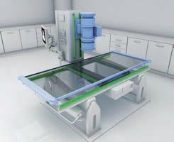
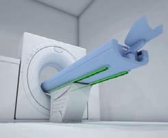
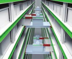
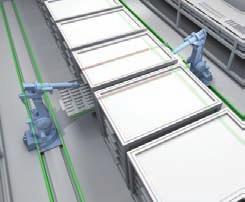
196 Guides suitable for all applications Railway Medical Logistics


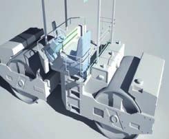

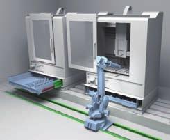
197 Aerospace Special Vehicles Industrial
Any reproduction, even partial, is allowed only by written permission by Rollco.
 COMPACT RAIL Every care has been taken to ensure the accuracy of the information contained in this catalogue, but no liability can be accepted for any errors or omissions. We reserve the right to make
Telescopic Line. General catalogue English.
 Telescopic Line General catalogue English www.rollon.com When you move. We move Rollon S.p.. was set up in 1975 as a manufacturer of linear motion components. Today Rollon group is a leading name in the
INDEX COMPACT RAIL: THE LINEAR MOTION SOLUTION...A5 ADVANTAGES OF COMPACT RAIL SYSTEM...A6 MAIN COMPONENTS...A8 GENERAL PERFORMANCE...
 INDEX COMPACT RAIL: THE LINEAR MOTION SOLUTION...A5 ADVANTAGES OF COMPACT RAIL SYSTEM...A6 MAIN COMPONENTS...A8 GENERAL PERFORMANCE...A10 18 SIZE...A11 28 SIZE...A13 43 SIZE...A17 63 SIZE...A22 ROLLERS...A25
Mono Rail.
 Mono Rail www.rollon.com When you move. We move Rollon S.p.A. was founded in 1975 as a manufacturer of linear motion components. Today Rollon group is a leading name in the design, production, and sale
...components in motion. Easy Rail
 ...components in motion Easy Rail Easy Rail Introduction The Easy Rail family have a compact cross-section and low-friction movement. Robust and Long Service Life Easy Rail s range of cross-sectional rail
EASY RAIL.
 EASY RAIL www.rollon.com About Rollon Development of global business Continual expansion and optimization of the portfolio 1975 Parent company, Rollon S.r.l., founded in Italy 1991 Founding of Rollon GmbH
Any reproduction, even partial, is allowed only by written permission by Rollco.
 EASYSLIDE Every care has been taken to ensure the accuracy of the information contained in this catalogue, but no liability can be accepted for any errors or omissions. We reserve the right to make changes
Easy Slide Rails ov -easy_slide_divider - U pdated
 Easy Slide Rails ov-easy_slide_divider - Updated - 18-09-2017 163 Easy Slide Rails Easy Slide Rails Introduction The Easy Slide family of linear rails have a compact cross-section and low-friction movement.
Easyslide FrontespizioEasyslide.indd 1 21/05/ :26:17
 Easyslide When you move. We move Rollon S.p.A. was founded in 1975 as a manufacturer of linear motion components. Today Rollon group is a leading name in the design, production, and sale of linear rails,
X-Rail FrontespizioXRai.indd 1 07/10/ :30:14
 X-Rail 1 Product explanation Product explanation X-Rail: orrosion resistant or zinc-plated steel linear bearings ig. 1 X-Rail is the product family of roller embossed guide rails for applications in which
Linear Guideways ov -linear -guidew ays-divider - U pdated
 Linear Guideways ov-linear-guideways-divider - Updated - 11-01-2017 163 Linear Guideways Linear Guideways Introduction L1016 Linear guideways Linear guideways are widely used throughout industry for heavy-duty
TELESCOPIC RAIL HEAVY
 TELESCOPIC RAIL HEAVY Every care has been taken to ensure the accuracy of the information contained in this catalogue, but no liability can be accepted for any errors or omissions. We reserve the right
 UNILINE www.motiontech.com.au bout Rollon Development of global business Continual expansion and optimization of the portfolio 1975 Parent company, Rollon S.r.l., founded in Italy 1991 Founding of Rollon
 A LEADING MANUFACTURER IN LINEAR MOTION GERALD SUMMERS is now an authorised distributor of Rollon TEL: 0800 055 6663 E-MAIL: SALES@GERALD-SUMMERS.CO.UK WWW.GERALD-SUMMERS.CO.UK CURVILINE www.rollon.com
Curviline FrontespizioCurviline.indd 1 07/10/ :24:20
 Curviline When you move. We move Rollon S.p.A. was founded in 1975 as a manufacturer of linear motion components. Today Rollon group is a leading name in the design, production, and sale of linear rails,
carriages to carry the load (taking into account any moment loads). Unlike the N series sliders these CS sliders do not have protective side seals.
. Unlike the N series sliders these CS sliders do not have protective side seals.") Light Duty Sliders, size 18 no side seal, front fixing Long Linear s L1918.CS Material Zinc plated steel body. Steel rollers (100Cr6) with metal (2Z) or rubber (2RS) seals. Technical notes To be used with
Light Duty Sliders, size 18 no side seal, front fixing Long Linear s L1918.CS Material Zinc plated steel body. Steel rollers (100Cr6) with metal (2Z) or rubber (2RS) seals. Technical notes To be used with
CURVILINE.
 CURVILINE www.rollon.com About Rollon Development of global business Continual expansion and optimization of the portfolio 1975 Parent company, Rollon S.r.l., founded in Italy 1991 Founding of Rollon GmbH
Slotted nut NMG. Housing nut GWR. Bosch Rexroth AG. for economical constructions. a min. 0,3. M A = tightening torque of slotted nut.
 R310EN 3301 (2009.08) Precision Ball Screw Assemblies Bosch Rexroth AG 113 Slotted nut NMG for economical constructions B D d d1 b M A = tightening torque of slotted nut a min. 0,3 Polyamide insert Designation
...components in motion. Miniature Linear Guideways
 ...components in motion Miniature Linear Introduction Miniature linear guideway systems are widely used throughout industry for precise, compact applications. Precise and Stainless The gothic arch shape
Miniature Ball Rail Systems
 R310EN 2210 (2004.06) The Drive & Control Company 2 Bosch Rexroth AG Linear Motion and Assembly Technologies Miniature-BRS R310EN 2210 (2004.06) Linear Motion Systems Ball Rail System Standard Ball Rail
TELESCOPIC RAIL.
 TEESCOPIC RAI www.rollon.com About Rollon Development of global business Continual expansion and optimization of the portfolio 1975 Parent company, Rollon S.r.l., founded in Italy 1991 Founding of Rollon
...components in motion. Curviline Rail
 ...components in motion Curviline Curviline Introduction The Curviline rail system offers a cost-effective solution to curvi-linear applications. Flexibility when you need it Constant radius, variable
TELESCOPIC RAIL.
 TEESCOPIC RAI www.rollon.com About Rollon Development of global business Continual expansion and optimization of the portfolio 1975 Parent company, Rollon S.r.l., founded in Italy 1991 Founding of Rollon
INDEX EASY RAIL: THE SOLUTION IS EASY...D4 EXAMPLES OF LOAD CAPACITIES...D5 ORDER CODES...D6 MOUNTING EXAMPLES...D7 TECHNICAL DATA...
 INDEX EASY RAIL: THE SOLUTION IS EASY...D4 EXAMPLES OF LOAD CAPACITIES...D5 ORDER CODES...D6 MOUNTING EXAMPLES...D7 TECHNICAL DATA...D8 STANDARD CONFIGURATIONS...D10 VERIFICATION UNDER STATIC LOAD...D12
Precision Modules PSK. The Drive & Control Company
 Precision Modules PSK The Drive & Control Company 2 Bosch Rexroth Coporation Precision Modules PSK R310A 2414 (2008.07) Linear Motion and Assembly Technologies Ball Rail Systems Roller Rail Systems Linear
Ball Rail Systems RE / The Drive & Control Company
 Ball Rail Systems RE 82 202/2002-12 The Drive & Control Company Rexroth Linear Motion Technology Ball Rail Systems Roller Rail Systems Standard Ball Rail Systems Super Ball Rail Systems Ball Rail Systems
Courtesy of CMA/Flodyne/Hydradyne Motion Control Hydraulic Pneumatic Electrical Mechanical (800)
") 01_1 Miniature st Headline_36 Ball Rail pt/14.4 Systems mm second line 2 Linear Motion and Assembly Technologies Miniature Ball Rail Systems Ball Rail Systems Roller Rail Systems Linear Bushings and Shafts
01_1 Miniature st Headline_36 Ball Rail pt/14.4 Systems mm second line 2 Linear Motion and Assembly Technologies Miniature Ball Rail Systems Ball Rail Systems Roller Rail Systems Linear Bushings and Shafts
Profi le rail guides LLR
 Profi le rail guides LLR Content The SKF brand now stands for more than ever before, and means more to you as a valued customer. While SKF maintains its leadership as the hallmark of quality bearings throughout
R310EN 2302 ( ) The Drive & Control Company
 The Drive & Control Company") R31EN 232 (26.4) The Drive & Control Company Bosch Rexroth AG Linear Motion and Assembly Technologies Ball Rail Systems Linear Bushings and Shafts Ball Screw Drives Linear Motion Systems Basic Mechanical
R31EN 232 (26.4) The Drive & Control Company Bosch Rexroth AG Linear Motion and Assembly Technologies Ball Rail Systems Linear Bushings and Shafts Ball Screw Drives Linear Motion Systems Basic Mechanical
MONO RAIL.
 MONO RAIL www.rollon.com About Rollon Development of global business Continual expansion and optimization of the portfolio 1975 Parent company, Rollon S.r.l., founded in Italy 1991 Founding of Rollon GmbH
...components in motion. Linear Guideways
 ...components in motion Linear 3 Linear Technical Information Linear Linear guideways are widely used throughout industry for heavy duty and precise applications. Linear from Automotion Components The
 A LEADING MANUFACTURER IN LINEAR MOTION GERALD SUMMERS is now an authorised distributor of Rollon TEL: 0800 055 6663 E-MAIL: SALES@GERALD-SUMMERS.CO.UK WWW.GERALD-SUMMERS.CO.UK MINIATURE MONO RAIL www.rollon.com
Product overview. 10 Bosch Rexroth Corporation Compact Modules R310A 2602 ( ) Compact Modules CKK. Compact Modules with ball screw drive (CKK)
 Compact Modules CKK. Compact Modules with ball screw drive (CKK)") 10 Bosch Rexroth Corporation R310A 2602 (2008.09) CKK with ball screw drive (CKK) Product overview are precision, ready-to-install linear motion systems characterized by their high performance and compact
10 Bosch Rexroth Corporation R310A 2602 (2008.09) CKK with ball screw drive (CKK) Product overview are precision, ready-to-install linear motion systems characterized by their high performance and compact
TELESCOPIC RAILS HARDENED TELESCOPIC RAILS FOR HIGHLY DYNAMIC APPLICATIONS 7.1 PRODUCT OVERVIEW 7.2 PART EXTENSIONS 7.
 7 TELESCOPIC RAILS HARDENED TELESCOPIC RAILS FOR HIGHLY DYNAMIC APPLICATIONS PAGE 106 PAGE 116 PAGE 120 PAGE 126 7.1 PRODUCT OVERVIEW 7.2 PART EXTENSIONS 7.3 FULL EXTENSIONS 7.4 LINEAR GUIDES 105 PRODUCT
> piston force up to 20,1 kn. > operating pressure 250/350 bar. > chemically nitrided body. > piston force up to 44,0 kn. > operating pressure 350 bar
 Vertical and link CLAMPS for DEMANDING TASKS vertical CLAMP > piston force up to 20,1 kn > operating pressure 250/350 bar > chemically nitrided body link CLAMP > piston force up to 44,0 kn > operating
Precision Modules PSK
 Precision Modules PSK The Drive & Control Company Rexroth Linear Motion Technology Ball Rail Systems Roller Rail Systems Standard Ball Rail Systems Super Ball Rail Systems Ball Rail Systems with Aluminum
TELESCOPIC-LINE. Semi-telescopic-rail LST. Telescopic-rail LSE. Linear guides with ball-cage LSS
 TELESCOPIC-LINE Semi-telescopic-rail LST Telescopic-rail LSE Linear guides with ball-cage LSS 1 Ball rails LSS, LST and LSE The ball rails produced by Nadella are very compact and flexible products. Made
R310EN 2211 ( ) The Drive & Control Company
 The Drive & Control Company") eline Ball Rail Systems R310EN 2211 (2006.04) The Drive & Control Company Bosch Rexroth AG Linear Motion and Assembly Technologies Ball Rail Systems Roller Rail Systems Linear Bushings and Shafts Ball
eline Ball Rail Systems R310EN 2211 (2006.04) The Drive & Control Company Bosch Rexroth AG Linear Motion and Assembly Technologies Ball Rail Systems Roller Rail Systems Linear Bushings and Shafts Ball
Linear Drive with Ball Screw Drive Series OSP-E..SB
 Linear Drive with Ball Screw Drive Series OSP-E..SB Contents Description Data Sheet No. Page Overview 1.30.001E 47-50 Technical Data 1.30.002E-1 to 5 51-55 Dimensions 1.30.002E-6, -7 56-57 Order instructions
Dynamic Elements Linear Slides Mechanical Drive Elements Accessories for Mechanical Drive Elements
 8 Dynamic Elements Mechanical Drive Elements Accessories for Mechanical Drive Elements The Dynamic Elements product group of the MB Building Kit System contains components which enable precise linear movement.
Any reproduction, even partial, is allowed only by written permission by Rollco.
 LINEAR UNIT E-SMART Every care has been taken to ensure the accuracy of the information contained in this catalogue, but no liability can be accepted for any errors or omissions. We reserve the right to
Precision Modules PSK
 Precision Modules PSK 2 Bosch Rexroth AG Precision Modules PSK R999000500 (2015-12) Identification system for short product names Short product name Example:: P S K - 050 - N N - 1 System = Precision Module
Ball. Ball cage. Fig.1 Structure of Caged Ball LM Guide Actuator Model SKR
 Caged all LM Guide Actuator Model Inner block all screw shaft Grease nipple Outer rail all cage all Structure and Features Fig.1 Structure of Caged all LM Guide Actuator Model Caged all LM Guide Actuator
Compact Modules. with ball screw drive and toothed belt drive R310EN 2602 ( ) The Drive & Control Company
 The Drive & Control Company") with ball screw drive and toothed belt drive R310EN 2602 (2007.02) The Drive & Control Company Bosch Rexroth AG Linear Motion and Assembly Technologies Ball Rail Systems Roller Rail Systems Linear Bushings
with ball screw drive and toothed belt drive R310EN 2602 (2007.02) The Drive & Control Company Bosch Rexroth AG Linear Motion and Assembly Technologies Ball Rail Systems Roller Rail Systems Linear Bushings
506E. LM Guide Actuator General Catalog
 LM Guide Actuator General Catalog A LM Guide Actuator General Catalog A Product Descriptions 506E Caged Ball LM Guide Actuator Model SKR.. A2-4 Structure and Features... A2-4 Caged Ball Technology... A2-6
Uniline System FrontespizioUnilineSystem.indd 1 22/11/ :32:41
 Uniline ystem 1 Uniline series Uniline series Uniline series description ig. 1 Uniline is a family of ready-to-install linear actuators. They consist of internal ompact Rail roller sliders and steel-reinforced
Inner block. Grease nipple. Fig.1 Structure of LM Guide Actuator Model KR
 LM Guide ctuator Model LM Guide + all Screw = Integral-structure ctuator Stopper Housing all screw Inner block Grease nipple Outer rail earing (supported side) Housing Stopper Double-row ball circuit earing
GN Telescope-Linear motion bearings
 GN 2410 Telescope-Linear motion bearings technical informations Specification Rail / Runner Heat treatable steel - zinc plated, blue passivated - Raceways hardened Balls Anti-friction bearing steel, hardened
LM Roller General Catalog
 General Catalog A Product Descriptions Features and Types... A10-2 Features of the... A10-2 Structure and Features... A10-2 Types of the... A10-4 Types and Features... A10-4 Point of Selection... A10-6
X-RAIL RL_XR_EN_12/10.
 X-RIL www.rollon.com bout Rollon evelopment of global business ontinual expansion and optimization of the portfolio 1975 Parent company, Rollon S.r.l., founded in Italy 1991 ounding of Rollon mbh in ermany
Technical features overview
 Technical features overview Reference Product name Extraction Size Material Stroke direction Snap Locking* 5 Damping Max. load capacity per pair [N] Product category Product Section Steel X* 4 A B BM EG
Guide units. For toolmaking, fixture manufacturing and machine engineering
 Guide units For toolmaking, fixture manufacturing and machine engineering Guide units in compliance with DIN, ISO and STEINEL standards or according to your specifications Guide pillars Guide and pillar
Linear Drive with Toothed Belt and Integrated Guide with Recirculating Ball Bearing Guide with Roller Guide Series OSP-E..BHD
 Linear Drive with and Integrated Guide with Recirculating Ball Bearing Guide with Roller Guide Contents Description Page Overview 11-14 Version with Recirculating Ball Bearing Guide Technical Data 15-17
Linear Drive with Toothed Belt Series OSP-E..B. Contents Description Overview Technical Data Dimensions Order Instructions 46
 Linear Drive with Toothed Belt Contents Description Page Overview 35-38 Technical Data 39-43 Dimensions 44-45 Order Instructions 46 35 The System Concept ELECTRIC LINEAR DRIVE FOR POINT-TO-POINT APPLICATIONS
Cross Roller Guide/Ball Guide General Catalog
 General Catalog A Product Descriptions Features and Types... A7-2 Features of the.. A7-2 Structure and Features... A7-2 Types of the.. A7-3 Types and Features... A7-3 Point of Selection... A7-4 Rated Load
STAR Ball Rail Tables TKK
 before operating X4 X8 X3 X1 X2 S1 S2 12 4 13 5 14 6 15 7 16 8 1 2 3 9 10 11 1 2 3 4 5 6 8.8 S3 X30 Indramat DANGER! AC-CONTROLLER High voltage Danger of electrical shock Do not touch electrical connnections
MINIRAIL Profiled miniature guideway
 MINIRAIL Profiled miniature guideway Table of Contents 1 Product overview and technical informations MINIRAIL a range of high-precision products.... 2 MINIRAIL overview accuracy classes:.... 3 MINIRAIL
series Linear guideways CG-serie 3.3 CG series
 series CG-serie 3.3 CG series 3.3.1 Properties of the linear guideways, series CG The HIWIN linear guideways of the CG series with O-arrangement of the ball tracks guarantee high torque loading capacity,
Bevel gearboxes. Catalogue
 Bevel gearboxes Catalogue INDEX Bevel gearbox description... page 2 Manufacturing features... page 2 Materials and components... page 4 Bevel gearbox selection... page 5 Thermal power limit... page 7
Compact Modules CKK/CKR 9-70
 Compact Modules CKK/CKR 9-70 with Ball Screw Drive and Toothed Belt Drive The Drive & Control Company 2 Compact Modules CKK/CKR 9-70 R310A 2624 (2009.05) Linear Motion and Assembly Technologies Ball Rail
Linear Bushings and Shafts Inch Series
 Industrial Hydraulics Electric Drives and Controls Linear Motion and Assembly Technologies Pneumatics Service Automation Mobile Hydraulics Linear Bushings and s Inch Series The Drive and Control Company
Contents. Page. 1. Product description. 2. The AXC line of linear axes. 3. AXLT line of linear tables. AXC and AXS product overview...
 SNR Industry Contents Page 3 1. Product description AXC and AXS product overview... 6-8 Dynamic load ratings of the linear motion systems... 9 Compact modules... 10-11 Linear tables... 12 Telescopic axes...
Electromechanical Cylinder EMC
 Courtesy of CMA/Flodyne/Hydradyne Motion Control Hydraulic Pneumatic Electrical Mechanical (800) 426-5480 www.cmafh.com The Drive & Control Company Linear Motion and Assembly Technologies Ball Rail Systems
Profile rail guides LLT
 Profile rail guides LLT Contents The SKF brand now stands for more than ever before, and means more to you as a valued customer. While SKF maintains its leadership as the hallmark of quality bearings throughout
Linear Actuator with Toothed Belt Series OSP-E..B
 Linear Actuator with Toothed Belt Series OSP-E..B Contents Description Data Sheet No. Page Overview 1.20.001E 21-24 Technical Data 1.20.002E-1 to 5 25-29 Dimensions 1.20.002E-6 30 Order Instructions 1.20.002E-7
LINEAR ROLLER SYSTEM with MR rail and R, R.T, R.S sliders
 NR R R N NR ROR YTM with MR rail and R, R.T, R. sliders The MR eries inear Rail ystem consists of a -section steel rail with internal convex raceways, where robust double row ball bearing rollers travel.
ROTARY MODULES. Rotary modules
 Rotary modules Rotary modules ROTARY MODULES Series Size Page Rotary modules RM swivel unit 156 RM 08 160 RM 10 162 RM 12 164 RM 15 168 RM 21 172 RM rotor 176 RM 50 180 RM 110 182 RM 200 184 RM 310 186
RSR. LM Guide Miniature Types Model RSR. Point of Selection. Point of Design. Options. Model No. Precautions on Use
 LM Guide Miniature Types Model Endplate LM block End seal LM rail Ball Grease nipple Cross section Point of Selection A Point of Design Options Model No. Precautions on Use Accessories for Lubrication
with MR rail and R, R.T, R.S sliders
 inear Roller earing ystem with MR rail and R, R.T, R. sliders N R R R N The MR eries inear Rail ystem consists of a -section steel rail with internal convex raceways, where robust double row ball bearing
Features of the LM Guide
 Features of the Functions Required for Linear Guide Surface Large permissible load Highly rigid in all directions High positioning repeatability Running accuracy can be obtained easily High accuracy can
Linear Bushings and Shafts
 Linear Bushings and Shafts 45 b 1cr RA 83 100.1 Linear Motion and Assembly Technologies STAR Linear Motion Technology Ball Rail Systems Standard Ball Rail Systems Ball Rail Systems with Aluminum Runner
Modular. Precise. Robust. AGE-S-XYZ Compensation Unit
 Modular. Precise. Robust. AGE-S-XYZ Compensation Unit Compensation unit compensating in XY- and Z-direction. Field of Application Palletizing, joining, and assembly of workpieces Advantages Your benefit
ORIGA Pneumatic Linear Drives OSP-L
 ORIGA Pneumatic Linear Drives OSP-L Very long lifetime and lowest leakage A NEW Modular Linear Drive System With this second generation linear drive Parker Origa offers design engineers complete flexibility.
Vertical Linear Drive with Toothed Belt and Integrated Recirculating Ball Bearing Guide Series OSP-E..BV
 Vertical Linear Drive with and Integrated Recirculating Ball Bearing Guide Series OSP-E..BV Overview...25-28 Technical Data...29-31 Dimensions...32-33 25 Features TOOTHED BELT DRIVE FOR VERTICAL MOVEMENTS
Active and Passive Brakes Series OSP-P
 Active and Passive Brakes Series OSP-P Contents Description Page Overview 51-52 Standard cylinder with Active brake 53-56 Plain bearing SLIDELINE with Active brake 33-34 Aluminium roller guide PROLINE
Axial-radial cylindrical roller bearings
 Axial-radial cylindrical roller bearings Designs and variants.............. 320 Bearing data..................... 321 (Boundary dimensions, tolerances) Product table 5.1 Axial-radial cylindrical roller
Active and Passive Brakes Series OSP-P
 Active and Passive Brakes Series OSP-P Contents Description Data Sheet No. Page Overview P-1.42.001E 69-70 Standard cylinder with Active brake P-1.42.002E 71-74 Plain bearing SLIDELINE with Active brake
CKR Compact Modules with Ball Rail Guides and Toothed Belt Drive. The Drive and Control Company
 CKR Compact Modules with Ball Rail Guides and Toothed Belt Drive The Drive and Control Company Bosch Rexroth Corp. Linear Motion and Assembly Technologies CKR RE 8 615 (03.006) Rexroth Linear Motion Technology
LINEAR BEARINGS & HOUSINGS
 LINEAR BEARINGS & HOUSINGS www.euro-bearings.com Tel. 01908 511733 email: sales@euro-bearings.com GENERAL INFORMATION Introduction Ball bushings are anti-friction bearings for linear motion. They offer
General Technical Data and Calculations
 12 Bosch Rexroth AG R310EN 2202 (2009.06) General Product Description General Technical Data and Calculations General notes The general technical data and calculations apply to all, i.e., to all ball runner
eline Profiled Rail Systems
 eline Profiled Rail Systems with Ball and Cam Roller Runner Blocks R310EN 2211 (2008.04) The Drive & Control Company Bosch Rexroth AG Linear Motion and Assembly Technologies Ball Rail Systems Roller Rail
Medical equipment. Press brakes EDM. Woodworking
 Ball screws Medical equipment Press brakes EDM Woodworking General Contents d Ø Load C o Rolling element Recommendations for selection Overview: ball screw nuts ---------------------------------------------------------------------------------------------------
Modular. Precise. Robust. AGE-S-XYZ Compensation Unit
 AGE-S Modular. Precise. Robust. AGE-S-XYZ Compensation Unit Compensation unit compensating in XY- and Z-direction Field of Application Palletizing, joining, and assembly of workpieces Advantages Your benefit
Slides. Dynamic and precise
 Slides Dynamic and precise Product catalog 2017 Latest version of the catalogs You can always find the latest version of our catalogs in the Download area of our website. Disclaimer This publication has
Берг АБ Тел. (495) , факс (495)
 , факс (495)") AUTOMATION Linear- and Rotary Modules Table of Contents 1 Product Overview............................................. 4 1.1 Selection of the Linear Modules................................. 8 1.2 Selection
AUTOMATION Linear- and Rotary Modules Table of Contents 1 Product Overview............................................. 4 1.1 Selection of the Linear Modules................................. 8 1.2 Selection
Single direction thrust ball bearings Double direction thrust ball bearings
 Thrust ball bearings Single direction thrust ball bearings... 838 Double direction thrust ball bearings... 839 Bearing data general... 840 Dimensions... 840 Tolerances... 840 Misalignment... 840 Cages...
Bearing retention and clearances
 Bearing retention and clearances Bearing retention 9 Radial retention 9 Axial retention 91 Positioning of single bearing assemblies 91 Positioning of two bearing assemblies 92 Axial retention processes
10 Thrust ball bearings
 10 Thrust ball bearings Designs and variants.............. 1010 Single direction thrust ball bearings... 1010 Double direction thrust ball bearings.. 1010 Cages............................ 1010 Bearings
Linear Actuator with Ball Screw Series OSP-E..S. Contents Description Overview Technical Data Dimensions 89
 Linear Actuator with Ball Screw Series OSP-E..S Contents Description Page Overview 79-82 Technical Data 83-88 Dimensions 89 79 The System Concept ELECTRIC LINEAR ACTUATOR FOR HIGH ACCURACY APPLICATIONS
Linear Guides Series OSP-P
 Linear Guides Series OSP-P NEW Contents Description Page Overview 31-32 Plain bearing guide SLIDELINE 33-34 Roller guide POWERSLIDE 35-38 Aluminium roller guide PROLINE 39-40 Recirculating ball bearing
Ball Rail Systems BSCL. Ball Runner Blocks, Ball Guide Rails, accessories
 Ball Rail Systems BSCL Ball Runner Blocks, Ball Guide Rails, accessories 2 Ball Rail Systems BSCL General product information The Ball Rail System Compact Line BSCL The new Ball Rail System BSCL (Ball
Rodless Pneumatic Cylinders Series OSP-P
 Rodless Pneumatic Cylinders Series OSP-P System Concepts & Components... 2-5 Technical Data... 7-9 Dimensions... 10-15 Active rakes... 16-19 Accessories (Mounts & Supports)... 20-29 Ordering Information...30
Vertical Linear Drive with Toothed Belt and Integrated Recirculating Ball Bearing Guide Series OSP-E..BV
 Vertical Linear Drive with Toothed Belt and Integrated Recirculating Ball Bearing Guide Series OSP-E..BV Contents Description Page Overview 25-28 Technical Data 29-33 Dimensions 34 Order Instructions 35
Actuator Line. General catalogue English. Part 1
 ctuator Line Part 1 General catalogue English www.rollon.com When you move. We move Rollon.p.. was founded in 1975 as a manufacturer of linear motion components. Today Rollon group is a leading name in
...our linkages, your solution. Rod Ends
 ...our linkages, your solution Technical Information Introduction All of our rod ends incorporate either a plain spherical bearing, ball bearing, or roller bearing. Below is an overview of each type. Plain
Vertical Linear Drive with Toothed Belt and Integrated Recirculating Ball Bearing Guide Series OSP-E..BV
 Vertical Linear Drive with and Integrated Recirculating Ball Bearing Guide Series OSP-E..BV Contents Description Page Overview 25-28 Technical Data 29-31 Dimensions 32-33 25 Parker Hannifin Corporation
EMC-HD. C 01_2 Subheadline_15pt/7.2mm
 C Electromechanical 01_1 Headline_36pt/14.4mm Cylinder EMC-HD C 01_2 Subheadline_15pt/7.2mm 2 Elektromechanischer Zylinder EMC-HD Short product name Example: EMC 085 HD 1 System = ElectroMechanical Cylinder
V SWISS MADE LINEAR TECHNOLOGY
 Excerpt from main catalogue inear modules V 11-15 SWISS MDE INER TECHNOOGY ine Tech inear modules Table of contents Product overview 6 7 Design fundamentals / ubrication / Maintenance 8 Profile cross-sections
RE / STAR Tolerance Rings STAR Ball Knobs, Knob and Lever Type Handles
 RE 2 970/.99 STAR Tolerance Rings STAR Ball Knobs, Knob and Lever Type Handles STAR Tolerance Rings Product Overview Tolerance rings are made of hard, embossed spring steel strip and belong to the class
Variable Displacement Plug-In Motor A6VE
 Electric Drives and Controls Hydraulics Linear Motion and Assembly echnologies Pneumatics Service Variable Displacement Plug-In Motor A6VE RE 91 606/06.05 1/16 Replaces: 05.99 echnical data sheet Series