Medical equipment. Press brakes EDM. Woodworking
|
|
|
- Hannah Pope
- 5 years ago
- Views:
Transcription

1 Ball screws


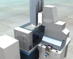
2 Medical equipment Press brakes EDM Woodworking
")


3 General Contents d Ø Load C o Rolling element Recommendations for selection Overview: ball screw nuts Basic dynamic load rating (C a ) Static load carrying capacity (C oa ) Critical rotating speed for screw shafts Permissible speed limit Lubrication Effi ciency and back-driving Axial play and preload Static axial stiffness of a complete assembly Screw shaft buckling Manufacturing precision Materials and heat treatments Recommendations for assembly Radial and moment loads Alignment Lubrication Designing the screw shaft ends Operating temperature Separating the nut from the screw shaft Starting-up the screw Other technical data Lead precision according to ISO Product information SD/BD miniature screws SDS/BDS/SHS miniature screws in stainless steel SH miniature screws SX/BX universal screws Accessories for SX/BX nuts SND/BND precision screws, DIN standard PND preloaded screws, DIN standard SN/BN precision screws PN preloaded screws SL/BL long lead screws SLT/BLT rotating nuts Standard machined ends Screw shaft accessories Calculation formulas Designation Roller screws and cylinders


4 Nuts for ball screws Nuts for ball screws Screw assembly Type of recirculation SD/BD Internal, by inserts Right hand lead Diameter, Catalogue page Screw accessories Nut accessories Preload for optimum rigidity Backlash elimination Axial play SD SD SD SD BD BD BD BD SD BD SDS/BDS Stainless steel optional SH External, by integrated tube 6 SH SH,7,7 SH SHS Stainless steel optional SX/BX Internal, by inserts SX SX SX SX SX SX BX BX BX BX BX BX SND/BND/PND Internal, by inserts SND SND BND BND PND PND - SND BND PND - SND BND PND - SND BND PND DIN VERSION 0 6 SND SND BND BND PND PND SN/BN/PN Internal, by inserts SN SN BN BN PN PN - SN BN PN - SN BN PN - SN BN PN 0 SN BN PN 6 SN BN PN SL/BL - SLD/BLD By faces SL SL SL SLD SL SL BL BL BL BLD BL BL SLT, BLT, Rotating nuts Accessories: FLBU, PLBU, BUF with SL/BL long lead screw

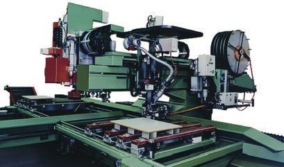
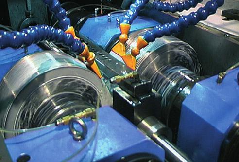
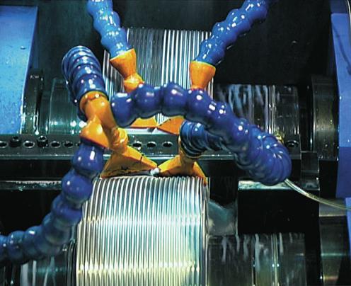
5 Recommendations for selection Recommendations for selection Only basic selection parameters are included. To make the very best selection of a ball screw, the designer should specify such critical parameters as the load profile, the linear or rotational speed, the rates of acceleration and deceleration, the cycle rate, the environment, the required life, the lead accuracy, the stiffness, and any other special requirement. If in doubt, please consult an SKF ball screw specialist before placing an order. Basic dynamic load rating (C a ) The dynamic rating is used to compute the fatigue life of ball screws. It is the axial load constant in magnitude and direction, and acting centrally under which the nominal life (as defi ned by ISO) reaches one million revolutions. Nominal fatigue life L The nominal life of a ball screw is the number of revolutions (or the number of operating hours at a given constant speed) which the ball screw is capable of enduring before the fi rst sign of fatigue (fl aking, spalling) occurs on one of the rolling surfaces. It is however evident from both laboratory tests and practical experience that seemingly identical ball screws operating under identical conditions have different lives, hence the notion of nominal life. It is, in accordance with ISO defi nition, the life achieved or exceeded by 90 % of a suffi ciently large group of apparently identical ball screws, working in identical conditions (alignment, axial and centrally applied load, speed, acceleration, lubrication, temperature and cleanliness). Service life The actual life achieved by a specifi c ball screw before it fails is known as service life. Failure is not only by fatigue (fl aking or spalling); but also by inadequate lubrication and wear; wear of the recirculation system, corrosion, contamination, and, more generally, by loss of the functional characteristics required by the application. Experience acquired with similar applications will help to select the proper screw to obtain the required service life. One must also take into account structural requirements such as the strength of screw ends and nut attachments, due to the loads applied on these elements in service. To attain L life performance a mean working load of up to 0 % of C a and a stroke higher than leads are permitted. Life test bench () SKF can help you to define this value in relation with the actual conditions of service.

6 Recommendations for selection Equivalent dynamic loads The loads acting on the screw can be calculated according to the laws of mechanics if the external forces (e.g. power transmission, work, rotary and linear inertia forces) are known or can be calculated. It is necessary to calculate the equivalent dynamic load. Radial and moment loads must be taken by linear bearing systems. It is extremely important to resolve these problems at the earliest conceptual stage. These forces are detrimental to the life and the expected performance of the screw. Fluctuating load When the load fl uctuates during the working cycle, it is necessary to calculate the equivalent dynamic load: this load is defi ned as that hypothetical load, constant in magnitude and direction, acting axially and centrally on the screw which, if applied, would have the same infl uence on the screw life as the actual loads to which the screw is subjected. Additional loads due, for example to misalignment, uneven loading, shocks, and so on, must be taken in account. Their infl uence on the nominal life of the screw is generally taken care of, consult SKF for advice. Static load carrying capacity (C oa ) d Ø Load C o Rolling element Ball screws should be selected on the basis of the basic static load rating C oa instead of on bearing life when they are submitted to continuous or intermittent shock loads, while stationary or rotating at very low speed for short duration. The permissible load is determined by the permanent deformation caused by the load acting at the contact points. It is defi ned by ISO standards as the purely axially and centrally applied static load which will create, by calculation, a total (rolling element + thread surface) permanent deformation equal to of the diameter of the rolling element. A ball screw must be selected by its basic static load rating which must be, at least, equal to the product of the maximum axial static load applied and a safety factor s o. The safety factor is selected in relation with past experience of similar applications and requirements of running smoothness and noise level (). Critical rotating speed for screw shafts The shaft is equated to a cylinder, the diameter of which is the root diameter of the thread. The formulas use a parameter the value of which is dictated by the mounting of the screw shaft (whether it is simply supported or fi xed). As a rule the nut is not considered as a support of the screw shaft. Because of the potential inaccuracies in the mounting of the screw assembly, a safety factor of 0.0 is applied to the calculated critical speeds. Calculations which consider the nut as a support of the shaft, or reduce the safety factor, require practical tests and possibly an optimization of the design (). () SKF can help you to define this value in relation with the actual conditions of service. 6
.")

7 Recommendations for selection Permissible speed limit Lubrication Efficiency and back-driving The permissible speed limit is that speed which a screw cannot reliably exceed at any time. It is generally the limiting speed of the recirculation system in the nut. It is expressed as the product of the rpm and the nominal diameter of the screw shaft (in mm). The speed limits quoted in this catalogue are the maximum speeds that may be applied through very short periods and in optimized running conditions of alignment, light external load and preload with monitored lubrication. Running a screw continuously at the permissible speed limit may lead to a reduction of the calculated life of the nut mechanism.! High speed associated with high load requires a large input torque and yields a relatively short nominal life (). In the case of high acceleration and deceleration, it is recommended to either work under a nominal external load or to apply a light preload to the nut to avoid internal sliding during reversal. The value of preload of screws submitted to high velocity must be that preload which ensures that the rolling elements do not slide (). Too high a preload will create unacceptable increases of the internal temperature. The lubrication of screws rotating at high speed must be properly considered in quantity and quality. The volume, spread and frequency of the application of the lubricant (oil or grease) must be properly selected and monitored. At high speed the lubricant spread on the surface of the screw shaft may be thrown off by centrifugal forces. It is important to monitor this phenomenon during the fi rst run at high speed and possibly adapt the frequency of relubrication or the fl ow of lubricant, or select a lubricant with a different viscosity. Monitoring the steady temperature reached by the nut permits the frequency of relubrication or the oil fl ow rate to be optimized. The performance of a screw is mainly dependant on the geometry of the contact surfaces and their fi nish as well as the helix angle of the thread. It is, also, dependant on the working conditions of the screw (load, speed, lubrication, preload, alignment, etc ). The direct effi ciency is used to defi ne the input torque required to transform the rotation of one member into the translation of the other. Conversely, the indirect effi ciency is used to defi ne the axial load required to transform the translation of one member into the rotation of the other one. It is used, also, to defi - ne the braking torque required to prevent that rotation. It is safe to consider that these screws are reversible or backdriveable under almost all circumstances. It is therefore necessary to design a brake mechanism if backdriving is to be avoided (gear reducers or brake). Friction Back driving torque T f > torque T r () SKF can help you to define this value in relation with the actual conditions of service. 7

8 Recommendations for selection Preload torque: Internally preloaded screws exhibit a torque due to this preload. This persists even when they are not externally loaded. Preload torque is measured when assembly is lubricated with ISO grade 6 oil. Starting torque: This is defi ned as the torque needed to overcome the following to start rotation: a) the total inertia of all moving parts accelerated by the energy source (including rotation and linear movement). b) the internal friction of the screw/nut assembly, bearing and associated guiding devices. In general, torque to overcome inertia (a) is greater than friction torque (b). The coeffi cient of friction of the high effi ciency screw when starting µ s is estimated at up to double the dynamic coeffi cient µ, under normal conditions of use. Axial play and preload Preloaded nuts are subject to much less elastic deformation than non-preloaded nuts. Therefore they should be used whenever the accuracy of positioning under load is important. Preload is that force applied to a set of two half nuts to either press them together or push them apart with the purpose of eliminating backlash or increasing the rigidity or stiffness of the assembly. The preload is defi ned by the value of the preload torque (see under that heading in the previous paragrah). The torque depends on the type of nut and on the mode of preload (elastic or rigid). Static axial stiffness of a complete assembly It is the ratio of the external axial load applied to the system and the axial displacement of the face of the nut in relation with the fi xed (anchored) end of the screw shaft. The inverse of the rigidity of the total system is equal to the sum of all the inverses of the rigidity of each of the components (screw shaft, nut as mounted on the shaft, supporting bearing, supporting housings, etc ). Because of this, the rigidity of the total system is always less than the smallest individual rigidity. Nut rigidity When a preload is applied to a nut, fi rstly, the internal play is eliminated, then, the Hertzian elastic deformation increases as the preload is applied so that the overall rigidity increases. The theoretical deformation does not take into account machining inaccuracies, actual sharing of the load between the different contact surfaces, the elasticity of the nut and of the screw shaft. The practical stiffness values given in the catalogue are lower than the theoretical values for this reason. The rigidity values given in the SKF ball screw catalogue are individual practical values for the assembled nut. They are determined by SKF based on the value of the selected basic preload and an external load equal to twice this preload. Lead Nut Lead + Shift Lead Elastic deformation of screw shaft This deformation is proportional to its length and inversely proportional to the square of the root diameter. According to the relative importance of the screw deformation (see rigidity of the total system), too large an increase in the preload of the nut and supporting bearings yields a limited increase of rigidity and notably increases the preload torque and therefore the running temperature. Consequently, the preload stated in the catalogue for each dimension is optimum and should not be increased. Screw shaft buckling The column loading of the screw shaft must be checked when it is submitted to compression loading (whether dynamically or statically). The maximum permissible compressive load is calculated using the Euler formulas. It is then multiplied by a safety factor of to, depending on the application. The type of end mounting of the shaft is critical to select the proper coeffi cients to be used in the Euler formulas. When the screw shaft comprises a single diameter, the root diameter is used for the calculation. When the screw comprises different sections with various diameters, calculations becomes more complex (). Screw () SKF can help you to define this value in relation with the actual conditions of service.
9 Recommendations for selection Manufacturing precision Generally speaking, the precision indication given in the designation defi nes the lead precisions see page - lead precision according to ISO - (ex. G - G7 ). Parameters other than lead precision correspond to our internal standards (generally based on ISO class 7 ). If you require special tolerances (for example class ) please specify when requesting a quotation or ordering. Materials and heat treatments Standard screw shafts are machined from steel which is surface hardened by induction (CrMo-NF EN0- for diameters > mm and CE for diameters mm). Standard nuts are machined in steel which is through hardened (0 Cr6 - NFA.6 or equivalent for diameters mm and carbon steel for diameters < mm). Hardness of the contact surfaces is 6-60 HRc, depending on diameter, for standard screws. Most assemblies made of stainless material have a surface hardness in the range 0 to HRc, depending on the type. The load rating of the catalogue are given only for standard screws. Number of circuits of balls A nut is defi ned by the number of ball turns which support the load. The number is changing, according to the product and the combination diameter/lead. It is defi ned by the number of circuits and their type. Recirculation inserts The standard products have been fi tted with composite ball recirculation inserts. System performance is improved because of the smoother ball recirculation. This results from the improved precision of the moulded insert when compared to the former steel insert. If the product is used in severe applications, or the insert is used to prevent collapse (especially in vertical applications), a steel version is available. In such cases, the specifi er should consult SKF Linear Motion to obtain the optimum solution. Working environment Our products have not been developed for use in an explosive atmosphere, consequently we cannot take any responsability for the use in this fi eld. NOTE: CrMo, an AFNOR reference is similar to AISI ; 0Cr6 is similar to AISI. () SKF can help you to define this value in relation with the actual conditions of service. 9

10 Recommendations for assembly Recommended assembly procedure Ball screws are precision components and should be handled with care to avoid shocks. When stored out of the shipping crate they must lie on wooden or plastic vee blocks and should not be allowed to sag. Screw assemblies are shipped, wrapped in a heavy gauge plastic tube which protects them from foreign material and possible pollution. They should stay wrapped until they are used. Radial and moment loads Any radial or moment load on the nut will overload some of the contact surfaces, thus signifi cantly reducing life (fi g. ). Alignment SKF linear guidance components should be used to ensure correct alignment and avoid non-axial loading. The parallelism of the screw shaft with the guiding devices must be checked. If external linear guidance proves impractical, we suggest mounting the nut on trunnions or gimbals and the screw shaft in self-aligning bearings. Mounting the screw in tension helps align it properly and eliminates buckling. Designing the screw shaft ends Generally speaking, when the ends of the screw shaft are specifi ed by the customer s engineering personnel, it is their responsability to check the strength of these ends. However, we offer in pages 6 to 9 of this catalogue, a choice of standard machined ends. As far as possible, we recommend their use. Whatever your choice may be, please keep in mind that no dimension on the shaft ends can exceed d o (otherwise traces of the root of thread will appear or the shaft must be made by joining pieces). A minimum shoulder should be suffi cient to maintain the internal bearing. Operating at high temperature will lower the hardness of the steel, alter the accuracy of the thread and may increase the oxidability of the materials or change lubricant properties. Lubrication Good lubrication is essential for the proper functioning of the screw and for its long term reliability (). Before shipping, the screw is coated with a protective fl uid that dries to a fi lm. This protective fi lm is not a lubricant. Depending on the selected lubricant, it may be necessary to remove this fi lm before applying the lubricant (there may be a risk of non-compatibility). If this operation is performed in a potentially polluted atmosphere it is highly recommended to proceed with a thorough cleaning of the assembly. Operating temperature Screws made from standard steel (see page 9) and operating under normal loads can sustain temperatures in the range - C to + C. Between + C and +0 C, SKF must be notifi ed so that it adapts the annealing procedure and checks that the application can be successful with a hardness below the standard minimum value (see page 9). Above +0 C, steels adapted to the temperature of the application should be selected (0Cr6, special steel, etc ). Consult SKF for advice. fig. YES! Axial loads fig. NO! Radial loads () SKF can help you to define this value in relation with the actual conditions of service.
. If the sleeve does not go over the diameter next to the ball track, adhesive tape can be used (b) or the sleeve held against the unmachined end (c). (fi g.")

11 Recommendations for assembly Separating the nut from the screw shaft Never screw the nut off the shaft without a mandrel to prevent the balls coming out (fi g. ).. Remove the retaining strap. Hold the sleeve against the ball track (a). If the sleeve does not go over the diameter next to the ball track, adhesive tape can be used (b) or the sleeve held against the unmachined end (c). (fi g. ). Without forcing, engage the nut in the screw thread. a fig. fig. Starting-up the screw After the assembly has been cleaned, mounted and lubricated, it is recommended that the nut is allowed to make several full strokes at low speed; to check the proper positioning of the limit switches or reversing mechanism before applying the full load and the full speed. NOTE: Intructions for most operations like mounting a nut on a screw shaft, a wiper on a nut, etc are available in separate sheets delivered with the product: please refer to them. b c

12 Standard technical data Lead precision according to ISO Lead precision is measured at C on the useful stroke l u, which is the threaded length decreased, at each end, by the length l e equal to the screw shaft diameter. G G7 G9 V 00p µm 7 l u e p v up e p v up e p v up mm µm () (0) (00) (60) (00) (00) (0) (00) (00) (00) (0) (00) (000) Lead accuracy control on a complete assembly
13 Standard technical data l u l e l o l s = useful travel = excess travel (no lead precision required) = nominal travel = specifi ed travel c = travel compensation (difference between l s and l o to be defi ned by the customer, for instance to compensate an expansion) e p = tolerance over the specifi ed travel V = travel variation (or permissible band width) V 00p = maximum permitted travel variation over 00 mm = maximum permitted travel variation over the useful V up travel l u V 00a = measured travel variation over 00 mm = measured travel variation over the useful travel V ua fig. l e Mean travel : the line which fits the curve best by method of least squares. v00a Threaded length l u v 00p µm + l e mm v up + - l 0 v ua l m 00 mm Case with value of c specified by the customer. fig. Case with c = 0 = standard version in case of no value given by the customer. fig. le Threaded length l u m + l e mm l 0 l e Threaded length l u m + l e v up e p e p c l m v up e p l 0 mm e p - l s -


14 SD/BD miniature screws Standard Recirculation Customised Smooth running and excellent backdriving with the new SD/BD internal recirculation nut. Nominal diameter to mm Lead: to mm Cylindrical nut with threaded end: easy mounting Excellent repeatibility: high positioning quality Internal recirculation with inserts: smooth running and good backdriving Backlash elimination by oversize balls on request (BD designation) Optional safety device (*): xr - xr - xr Optional wipers (*): For all sizes Corrosion resistant screw (see page ) (*) It is not possible to supply safety device and wipers in the same nut. Nominal Right Maximum Basic load ratings Number Maximum Reduced Mass Mass Inertia Designation diameter hand length of circuits axial maximum of nut of screw of one lead dynamic static of balls play axial play shaft metre of (on request) screw shaft P h C a C oa mm mm mm kn kn mm kg kg/m kgmm, 00,,6 0,07 0,0 0,0 0,, SD/BD x, R 00 00,,,, 0,07 0,07 0,0 0,0 0,00 0,0 0, 0,,, SD/BD x R SD/BD x R ,9,0,,6 6,, 0,07 0,07 0,07 0,0 0,0 0,0 0,0 0,066 0,0 0,67 0,7 0,7,0,, SD/BD x R SD/BD x R SD/BD x R 00 6,0 9,0 0,07 0,0 0,0,0,0 SD/BD x R , 7,6,7 6,, 7,0, 0,07 0,07 0,07 0,0 0,0 0,0 0,0 0, 0,0,,0, 9,7,9 0,7 SD/BD x R SD/BD x R SD/BD x R
15 SD BD A A N A D d d D M D Designation Screw shaft Nut Without With Tightening Without wiper wipers spanner wiper mm d d D M A +/-0, A (FACOM) N A D D h 6g ± 0, SD/BD x, R 6, 7,6 7, Mx,, 7, 6-A,,, SD/BD x R SD/BD x R, 7, 9,,9 9,,0 M7x Mx,0,0,0-7,,0 6-A 6-A,,,,0, - SD/BD x R SD/BD x R SD/BD x R 9,9 9, 9,,,,,0,,0 Mx Mx Mx,0,0 6,0,,0,0,0,0,0 6-A 6-A 6-A,,,,, - -, - SD/BD x R,9,7 7,0 Mx, 0,0,0,0 6-A, - - SD/BD x R SD/BD x R SD/BD x R,,7,6,6,, 9,,,0 Mx, M6x, M6x, 7,0,0 6,0 7,0,0 6,0,0,0,0 6-A 6-A 6-A,,,, - 9,,, 9, Designation: see page 9
 Optional wipers: For all sizes Material for both shaft and nut: X0Cr (AISI")
 screw shaft")

16 SDS/BDS/SHS miniature screws in stainless steel Standard SDS Standard SHS Customised SDS Nominal diameter 6 to mm Lead: to mm Cylindrical nut with threaded end: easy mounting Excellent repeatibility: high positioning quality Backlash elimination by oversize balls on request (BDS designation) Optional wipers: For all sizes Material for both shaft and nut: X0Cr (AISI equivalent) Balls are in XCrMo7 (AISI C equivalent) except for size xr (SDS/BDS): balls are in 0 Cr6 (AISI equivalent) Nominal Right Maximum Basic load ratings Number Maximum Reduced Mass Mass Inertia Designation diameter hand length of circuits axial maximum of nut of screw of one lead dynamic static of balls play axial play shaft metre of (on request) screw shaft P h C a C oa mm mm mm kn kn mm kg kg/m kgmm 6 00,0, x, 0,0 0,0 0,0 0, 0,7 SHS 6x R, 00,, 0,07 0,0 0,0 0,, SDS/BDS x, R 00,6,7 0,07 0,0 0,06 0,, SDS/BDS x R ,,0,,,,6 0,07 0,07 0,07 0,0 0,0 0,0 0,0 0,06 0,06 0,67 0,7 0,7,0,, SDS/BDS x R SDS/BDS x R SDS/BDS x R 00,7, 0,07 0,0 0,07,0,0 SDS/BDS x R 00 00,0,7,0, 0,07 0,07 0,0 0,0 0,066 0,,,0 9,7,9 SDS/BDS x R SDS/BDS x R
17 SDS BDS A A N A D d d D M D Designation Screw shaft Nut Without With Tightening Without wiper wipers spanner wiper mm d d D M A +/-0, A (FACOM) N A D D h 6g ± 0, SHS 6x R,7 6,0, Mx,0-7, 6-A,, - SDS/BDS x, R 6, 7,6 7, Mx,0,, 7, 6-A,,, SDS/BDS x R, 9, 9, M7x,0,0,0 7, 6-A,,, SDS/BDS x R SDS/BDS x R SDS/BDS x R 9,9 9, 9,,,,,0,,0 Mx,0 Mx,0 Mx,0,,0,0,,0,0,0,0,0 6-A 6-A 6-A,,,,,,,,, SDS/BDS x R,9,7 7,0 Mx,,0,0,0 6-A, 7, 7, SDS/BDS x R SDS/BDS x R,,7,, 9,, Mx, M6x, 7,0,0 7,0,0,0,0 6-A 6-A,,,,,, Designation: see page 9 7


18 SH miniature screws Standard Recirculation Customised Rolled thread ball screw with ball recirculation by integrated tube. Nominal diameter 6 to,7 mm Lead: to,7 mm Nut with threaded end for easy mounting High positioning accuracy Increased security: optional reinforced safety device available on request in size SH,7x,7R Wipers available on request for size SH,7x,7R It is not possible to supply safety device and wipers in the same nut. Nominal Right Maximum Basic load ratings Number Maximum Reduced Mass Mass Inertia Designation diameter hand length of circuits axial maximum of nut of screw of one lead dynamic static of balls play axial play shaft metre of (on request) screw shaft P h C a C oa mm mm mm kn kn mm mm kg kg/m kgmm 6 00,, x, 0,0 0,0 0,0 0, 0,7 SH 6 x R 00,, x, 0,07 0,0 0,00 0,0, SH x R,7,7 00, 9,0 x, 0,07 0,0 0,0 0,7, SH,7 x,7 R
19 A A N A D d d D M D Designation Screw shaft Nut Tightening Without spanner wiper d d D M A A (FACOM) N A D D h 6g ± 0, ± 0, mm mm SH 6 x R,7 6,0, M x 7, 6.A,, - SH x R 7,9 9,9,0 M x 9 9,0 6.A,,, SH,7 x,7 R,,0 9, M x, 0,0 6.A,, - Designation: see page 9 9

20 SX/BX universal screws Standard Recirculation Customised Rolled thread ball screw internal recirculation nut with threaded end. Standard version: composite inserts Special version: steel inserts which can act as a safety device for severe requirements or vertical applications Contact us. Nominal diameter to 6 mm Lead: to mm Cylindrical body of minimum diameter to simplify assembly Lubrication hole for nipple or automatic SKF system, positioned relative to the ISO thread Handling screw: nut with axial play Screw shaft can be phosphated on request Wipers available Backlash elimination by oversize balls on request (BX designation) Nut mounting fl anges available Screw shaft accessories: FLBU - PLBU & BUF off the shelves. (see pages to ) Nominal Right Maximum Basic load ratings Number Maximum Reduced Preload Mass Mass Inertia Designation diameter hand length of circuits axial maximum torque of nut of screw of one lead dynamic static of balls play axial play BX shaft metre of (on request) average screw shaft P h C a C oa T pr mm mm mm kn kn mm mm Nm kg kg/m kgmm 700,, 0, 0,0 0, 0,7,0 SX/BX x R ,, 7,,7 0, 0, 0,0 0,0 0,7 0, 0,9 0,6,, SX/BX x R SX/BX x R ,,9 0,,7 0, 0, 0,0 0,0 0, 0, 0, 0,79,6, SX/BX x R SX/BX x R , 6,6 6, 7, 0, 0, 0,0 0,0 0, 0,6 0,66, 9,0, 9 7 SX/BX x R SX/BX x R 0 700,9 9, 6 0, 0,0,0,,6 76 SX/BX 0 x R ,7, 6 0, 0,0,,90,0 99 SX/BX 6 x R
21 SX BX A Wiper N Wiper 90 D d d M x x Lubrication: Q A A A Designation Screw shaft Nut Lubrication hole Tightening spanner d d D M A A Q A N A js 6g mm mm SX/BX x R,7 9, M x, M6 x HN SX/BX x R SX/BX x R,7,,6,6 M x, M x, M6 x M6 x HN6 HN6 SX/BX x R SX/BX x R,7 7,,6,0 M x, M x, M6 x M6 x HN7 HN7 SX/BX x R SX/BX x R 6,7,0 9,6 9, 60 6 M6 x, M60 x,0 6 9 M6 x M x HN9 HN9 SX/BX 0 x R,0 9,7 7 M7 x,0 9 M x HN SX/BX 6 x R 7,0 6, 9 M x,0 9 M x HN Designation: see page 9


22 FHRF round flanges for SX/BX nuts SX nut SX nut with fl ange Flange A A J G H Nominal Dimensions Designation diameter P h A A G H J h h h js mm M FHRF 70 M6 M FHRF FHRF M6 M FHRF FHRF 70 M M FHRF x FHRF x 0 0 M 9 FHRF M 6 FHRF 6


23 FHSF square flanges for SX/BX nuts SX nut SX nut with fl ange Flange A A N L J J Nominal Dimensions Designation diameter P h A A L J J N h h h js mm 60 6,6 6,6 FHSF , 7, 9,0 9,0 FHSF FHSF ,, 9,0 9,0 FHSF FHSF ,0,,0,0 FHSF x FHSF x 0 0 9,0,0 FHSF ,0,0 FHSF 6 On special request, trunnion flanges are available.

24 SND/BND precision screws, DIN standard 690 Standard Recirculation With fl anged housing Rolled thread ball screw with internal recirculation nut. Standard version: composite inserts Special version: steel inserts which can act as a safety device for severe requirements or vertical applications Contact us. Nominal diameter to 6 mm Lead: to mm Lubrication hole for nipple or automatic SKF system Compact nut with integral fl ange for simple mounting and axial play Ground fl anged nut: precise mounting Wipers available Backlash elimination by oversize balls on request (BND designation) Screw shaft can be phosphated on request Screw shaft accessories: FLBU - PLBU & BUF off the shelves (see pages to ) Nominal Right Maximum Basic load ratings Number Maximum Reduced Preload Mass Mass Inertia Designation diameter hand length of circuits axial maximum torque of nut of screw of one lead dynamic static of balls play axial play BND shaft metre of (on request) average screw shaft P h C a C oa T pr mm mm mm kn kn mm mm Nm kg kg/m kgmm 00 00,,7, 7,0 x, 0,0 0,07 0,0 0,0 0,0 0, 0, 0,,0,,0 0,7 SND/BND x R SND/BND x R 700,7, 0, 0,0 0,0 0,,00,0 SND/BND x R ,0,,7,7 0, 0, 0,0 0,0 0, 0, 0,9 0,6,0,0,0,0 SND/BND x R SND/BND x R ,,6,, 0, 0, 0,0 0,0 0, 0, 0, 0,,60,60 6,0 69,0 SND/BND x R SND/BND x R , 6,6 6, 7, 0, 0, 0,0 0,0 0,6 0,6 0,6, 9,00, 9,0 7,0 SND/BND x R SND/BND x R ,6 7,6 0, 0,0 0,,7,60 76,0 SND/BND 0 x R ,,9 0, 0,0,,,00 99,0 SND/BND 6 x R
25 SND BND L L Lubrification hole M6x L 0' D (6x) D ØIT D6 D d d D -0, -0, DESIGN 90 Lubrification hole Mx 0 L L 7 L (x) D ØIT L tn DESIGN 0 90 Designation Screw shaft Nut Design d d D D D D 6 L tn L L 7 L L L g6 H h h mm SND/BND x R SND/BND x R,7,6,,,,, 7,0 7 SND/BND x R,7 9, 6 7 6,6, SND/BND x R SND/BND x R,7,,6,6 6,6 6,6 6 6, 7,0 SND/BND x R SND/BND x R,7 7,,6, ,0 9,0 0 0, 69, SND/BND x R SND/BND x R 6,7,0 9,6 9, ,0 9,0 9 9, 9, SND/BND 0 x R,0 9,7 7 9,0 9,0 SND/BND 6 x R 7,0 6, 90,0 9,0 9 9 Designation: see page 9

26 PND preloaded screws, DIN standard 690 Standard Recirculation With plummer housing Rolled thread ball screw with internal recirculation nut. Standard version: composite inserts Special version: steel inserts which can act as a safety device for severe requirements or vertical applications Contact us. Nominal diameter to 6 mm Lead: to mm Lubrication hole for nipple or automatic SKF system One-piece nut with integral fl ange offering an internal preload for optimum rigidity Wipers available Screw shaft can be phosphated on request Screw shaft accessories: FLBU - PLBU & BUF off the shelves (see pages to ) Nominal Right Maximum Basic load ratings Number Preload Mass Mass Inertia Designation diameter hand length of circuits torque of nut of screw of one Preload for lead dynamic static of balls average shaft metre of optimum screw shaft rigidity P h C a C oa T pr mm mm mm kn kn Nm kg kg/m kgmm 00 00,7,7, 7,0 x x x, 0,0 0, 0, 0,,0,,0 0,7 PND x R PND x R 700,, x 0, 0,,00,0 PND x R ,0,,7, x x 0, 0,0 0, 0,9,0,0,0,0 PND x R PND x R ,,6,, x x 0, 0,6 0, 0,9,60,60 6,0 69,0 PND x R PND x R ,, 6,,7 x x 0,7,7,,0 9,00, 9,0 7,0 PND x R PND x R ,6 7,6 x,7,,60 76,0 PND 0 x R ,,9 x,6,,00 99,0 PND 6 x R 6
27 S S+ S S Preload A displacement s is ground into the nut ball track between the two series of recirculation inserts: this displacement is made in an unused part of the track. The balls thus have two points of contact even under small external loads. L L Lubrification hole M6x L 0' D (6x) D ØIT D6 D d d D -0, -0, DESIGN 90 Lubrification hole Mx 0 L L 7 L (x) D ØIT L tn DESIGN 0 90 Designation Screw shaft Nut Design d d D D D D 6 L tn L L 7 L L L g6 H h h mm PND x R PND x R,7,6,,,, 7 77 PND x R,7 9, 6 7 6,6 0 PND x R PND x R,7,,6,6 6,6 6, PND x R PND x R,7 7,,6, ,0 9, PND x R PND x R 6,7,0 9,6 9, ,0 9, PND 0 x R,0 9,7 7 9,0 PND 6 x R 7,0 6, 90, Designation: see page 9 7
28 SN/BN precision screws Standard Recirculation Customised Rolled thread ball screw with internal recirculation nut. Standard version: composite inserts Special version: steel inserts which can act as a safety device for severe requirements or vertical applications Contact us. Nominal diameter to 6 mm Lead: to mm Lubrication hole for nipple or automatic SKF system Compact nut with integral fl ange for simple mounting and axial play Ground fl anged nut: precise mounting Wipers available Backlash elimination by oversize balls on request (BN designation) Screw shaft can be phosphated on request Screw shaft accessories: FLBU - PLBU & BUF off the shelves (see pages to ) Nominal Right Maximum Basic load ratings Number Maximum Reduced Preload Mass Mass Inertia Designation diameter hand length of circuits axial maximum torque of nut of screw of one lead dynamic static of balls play axial play BN shaft metre of (on request) average screw shaft P h C a C oa T pr mm mm mm kn kn mm mm Nm kg kg/m kgmm 00,, 0,0 0,0 0,0 0,, SN/BN x R 700,7, 0, 0,0 0,0 0,,0 SN/BN x R ,0,,7,7 0, 0, 0,0 0,0 0, 0, 0, 0,6,, SN/BN x R SN/BN x R ,,6,, 0, 0, 0,0 0,0 0, 0, 0,,,6, SN/BN x R SN/BN x R , 6,6 6, 7, 0, 0, 0,0 0,0 0,6 0,6 0,6,6 9,0, 9 7 SN/BN x R SN/BN x R ,6 7,6 0, 0,0 0,,9,6 76 SN/BN 0 x R ,,9 0, 0,0,,70,0 99 SN/BN 6 x R
29 SN BN A A A A = = Q D D +0, -0, d d D -0, -0, D J D Designation Screw shaft Nut Lubrication hole d d D D A A A A J D Q g9 js mm SN/BN x R,7,, 0 6 x. M6 SN/BN x R,7 9, 7 6, 0 6 x 6.6 M6 SN/BN x R SN/BN x R,7,,6, , 7, x x 6.6 M6 M6 SN/BN x R SN/BN x R,7 7,,6,0 70 7, 79, x x 9.0 M6 M x SN/BN x R SN/BN x R 6,7,0 9,6 9, 6 0 9, 9, x x 9.0 M6 M x SN/BN 0 x R,0 9,7 7 99, x M x SN/BN 6 x R 7,0 6,,0 6 6 x M x Designation: see page 9 9

30 PN preloaded screws Standard Recirculation Customised Rolled thread ball screw with internal recirculation nut. Standard version: composite inserts Special version: steel inserts which can act as a safety device for severe requirements or vertical applications Contact us. Nominal diameter to 6 mm Lead: to mm Lubrication hole for nipple or automatic SKF system One-piece nut with integral fl ange offering an internal preload for optimum rigidity Wipers available Screw shaft can be phosphated on request Screw shaft accessories: FLBU - PLBU & BUF off the shelves (see pages to ) Nominal Right Maximum Basic load ratings Number Preload Mass Mass Inertia Designation diameter hand length of circuits torque of nut of screw of one Preload lead dynamic static of balls PN shaft metre of for optimum average screw shaft rigidity P h C a C oa T pr mm mm mm kn kn Nm kg kg/m kgmm 00,7, x 0,0 0,, PN x R 700,, x 0, 0,7,0 PN x R ,0,,7, x x 0, 0,0 0, 0,6,, PN x R PN x R ,,6,, x x 0, 0,6 0,6,7,6, PN x R PN x R ,, 6,,7 x x 0,7,7 0,,0 9,0, 9 7 PN x R PN x R ,6 7,6 x,7,,6 76 PN 0 x R ,,9 x,6,0,0 99 PN 6 x R 0
31 S S+ S S Preload A displacement s is ground into the nut ball track between the two series of recirculation inserts: this displacement is made in an unused part of the track. The balls thus have two points of contact even under small external loads. A A A A = = Q D D +0, -0, d d D -0, -0, D J D Designation Screw shaft Nut Lubrication hole d d D D A A A A J D Q g9 js mm PN x R,7, 0 6 x. M6 PN x R,7 9, x 6.6 M6 PN x R PN x R,7,,6, x x 6.6 M6 M6 PN x R PN x R,7 7,,6, x x 9.0 M6 M x PN x R PN x R 6,7,0 9,6 9, x x 9.0 M6 M x PN 0 x R,0 9, x M x PN 6 x R 7,0 6, 6 6 x M x Designation: see page 9

32 SL/BL long lead screws Standard Recirculation Customised A new ball circulation system allowing high linear speed and low noise level. Nominal diameter to 0 mm Lead: to 0 mm Lubrication hole for nipple or automatic SKF system Two versions: - nut with axial play SL - nut with backlash elimination by oversize balls BL Double protection with polyamide wipers and brush wipers (WPR = with brush wipers NOWPR = without brush wipers) Screw shaft can be phosphated on request Screw shaft accessories: FLBU - PLBU & BUF off the shelves (see pages to ) Nominal Right Maximum Number SL BL Mass Mass Inertia Designation diameter hand length of circuits Basic load Maximum Preload of nut of screw of one lead of balls ratings axial play torque BL shaft metre of average screw shaft P h C a C oa S ap T pr mm mm mm kn kn mm Nm kg kg/m kgmm /m x,7 x,7,0,6,6,0 0,0 0,0 0, 0, 0,6 0,7,, SL/BL x R SL/BL x R x,7 x, x, x 0,,7 6,0 6,0,7 6, 6, 6,,6 0,0 0,0 0,0 0,0 0,9 0,9 0,9 0, 0,,0 0,9 0,7,,,, SL/BL x R SL/BL x R SLD/BLD x R SL/BL x R x,7 x,7,, 9,, 0,0 0, 0, 0,,,,, 0 0 SL/BL x R SL/BL x R x,7 9,, 0,,9,, 60 SL/BL 0 x 0 R
33 SL BL A = = Q A A A D D J L D -0, -0, d d D -0, -0, D Lubrification hole M6x 0 (6x) D ØIT J D See table below DESIGN 90 Designation Screw shaft Nut Lubrication hole mm d d D D A A A A J L D Q g9 js SL/BL x R SL/BL x R,7,,, 7 7 7,,6 66, 77, x x 6.6 M6 M6 SL/BL x R SL/BL x R SLD/BLD x R SL/BL x R 7,,, 6,9 0,0,, 9, g6 g ,,0,0,0 66, 0, 0,, x x x x 6.6 M6 M6 M6 (Design ) M6 SL/BL x R SL/BL x R,, 7,7, ,, 6,, x x M6 M x SL/BL 0 x 0 R, 9,,, x M x Designation: see page 9


34 Rotating nut Concept The nut rotates inside bearings and moves along the fi xed long lead screw shaft. The drive motor moves with the nut, so inertia & critical speed problems, associated with a long rotating shaft, are minimised. Design details 7 series angular contact bearings are directly mounted on the nut. They are preloaded in 0 confi guration in order to fully support the torque due to the belt tension. Nilos seals protect these bearings against pollution and permit lubrication for life. Two versions available: * Ball screw with axial play: SLT * Ball screw with backlash elimination: BLT Two brush wipers are mounted in the standard confi guration for better protection. Ball screw lubrication: through the nipple placed on the housing external diameter in the standard version, or as an option through the screw shaft. Ball nut greased with SKF LGMT. Other lubricants possible on request. Benefits Easy and simple to incorporate. Compact solution, ready to use. Fixed screw shaft: simplifi ed mounting. Inertia considerably reduced: 00 kgmm instead of 6000 kgmm for a screw shaft, x -. m stroke. Smaller, lighter, lower power motors. Higher linear speeds: up to m/min. Ball screw capacities Bearing axial capacities Size Dynamic capacity Static capacity Dynamic capacity Static capacity C a C oa C a C oa kn kn kn kn x x 9,, 96,6 0, 6, 6, 6,0 6,0 x x x 9,, 0,0, 7,,7 7,0 7,0 7,0 76, 76, 76, x x,7, 76,7, 9,6,0 9,,0 0x0 9,,,0 6,0
35 Rotating nut inertia Size Inertia Mass of Pulley support rotating nut kgmm kg x x,,6 Rotating nut capacities Size Max. transmissible Max. transmissible torque axial load Nm kn x x 0 0 6, 6, x x x , 7, 7, x x x ,0 7,,7 x x ,, x x 6,0 9, 0x0, 0x0 0,0 L L7 L9 Z x H Z x H L L L6 Ø Ø Ø Ø6 Ø R L Ø7 Ø H R J J L L L Ø Ø Ø Ø Ø Ø6 Ø7 L L L L L L L6 L7 L L9 R R J J ZxH ZxHx H useful depth Designation h g6 max max mm SLT/BLT x SLT/BLT x 7, 7, 0,0 0, ,0 6,,, 9,9 9,9 7 7,9,9,,9,, 0, 0, 0, 0, 6xØ9 6xØ9 6xM6x 6xM6x M6x M6x SLT/BLT x SLT/BLT x SLT/BLT x 0 0 0,0,0,0 9, 9, 9, , 6,,7,,, 7, 7, 7, 9 9 9,,, 7,,,7,0,0,0 0, 0, 0, 0, 0, 0, xØ9 6xØ9 6xØ9 6xM6x 6xM6x 6xM6x M6x M6x M6x SLT/BLT x SLT/BLT x 60 9,0 9,0,0 7, , 9, 7 9,,, 9,0,7 0 7,,,0, 0,,6 0,,6 7 0 xø9 xø9 6xM6x 6xM6x Mx Mx SLT/BLT 0x0 70,0 70,0 70,,, 0,,,7,6, xø 6xMx0 Mx All tolerances js if not specified.
36 Shaft end combinations In the order code, shaft end machining is defi ned by: - one letter for Ø < mm - two letters for Ø mm resulting from the combination of two machined ends (see designation page 9). Machined ends are represented in details in page 7 for Ø < mm and page for Ø mm. Ø < mm Ø mm Order code Two machined ends Order code Two machined ends A (without length indication) cut only AA (without length indication) cut only A (+ length) cut + annealed B + BA A + A F * + FA * A + A G * + GA * A + A H + HA A + A J M + + JA MA A + A A + A UA end machining S (+ length) Ends to root diameter, any possible lengths SA (+ length) UA n (+ length) Ends to root diameter d, any possible lengths. End machined to diameter d under induction hardening, any possible lengths. Dimensions Ød Ød mm mm K Keyway K Keyway x,7 9 Z To customer s drawing Z To customer s drawing x,7 * Attention! This mounting requires the greatest precautions. Please contact us. x x x x,7,,7, 9 9 n UA: end machined to diameter d under induction hardening, any possible lengths. x x DIN x x x x,7 7, 6,0 7,, 6,9 6 6 x x x x 6,7,0,, d d 0 x 0 x 0,0, 6 x 7,0 6


37 Standard end machining for nominal diameter < mm Special ends are machined to customers drawing on request. For SD - SH Type Type Type Type Type Keyway d d B B B B B B 6 G G m d 6 c b a d 7 r a a b e j S Keyway h7 js7 js js js H js 6g + 0, h/h h maxi N9 +0, DIN , 7 M x 0,7 7,0 0,, 0,,,9 7 6,6 9 M x 0, 7, 0,7, 0,,,7 0, ,7 M6 x 7, 0,,7 0,,, 0, /, , M x, 0,9 7,6 0,, 6, 0,, 0, A x x 6 9,0 M x,,, 9,6 0,, 7, 0, 6, 0, A x x 7
38 Standard end machining for nominal diameter mm Standard shaft ends for ball screws, nominal diameter mm, have been developed to suit the SKF thrust bearings FLBU, PLBU and BUF. These standard ends are the same for all screw types. However, for the SL/BL long lead screw, an additional shoulder, part of the threaded length, will be machined to protect the wiper and nut thread during assembly (both sides). Apart from this, the end itself is the same for all screw types. End bearing D Machined end type FLBU A or A PLBU A or A BUF A or A For SD/BD - SX/BX - SN/BN/PN - SND/BND/PND Size d d d d d B B B B B B 6 B 7 B 9 d G G m d 6 c c b a d 7 r a Keyway to DIN 6 a N9 xl xb h7 h6 h6 h7 js js js H js 6g + 0, h h h fixed end fixed end + 0 (type A) (type A) / / / / / / / Mx0.7 Mx M7x Mx M0x. Mx. M0x / /.. 0. / /.. 0. / / Axx Axx Axx Axx Ax7x Ax7x Axx0 Axx Axx Axx Axx Ax7x Ax7x Axx0 For SL/BL only Size d d d d d B B B B B B 6 B 7 B 9 d G G m d 6 c c b a d 7 r a Keyway to DIN 6 a N9 xl xb h7 h6 h6 h7 js js js H js 6g + 0, h h h fixed end fixed end + 0 (type A) (type A) x 7 / M7 x Axx Axx x 7 / M7 x Axx Axx x x x M x M x M x /. 0. /. 0. / Axx Axx Axx Axx Axx Axx x x 0 0 / / M0 x. M0 x Ax7x Ax7x Ax7x Ax7x 0 x M x / Ax7x Ax7x / for end types A or A
39 Standard machined ends Threaded length = total length - end length (n) : end length Type A For SL/BL only Type A Ra d G d For SL/BL only 0 C x B 7 x d 0 c x B 7 x d B c x b a x d 7 G (B ) B c x For other types Ra d G d For other types b a x d 7 c x c x G B (B ) B Type A d G For SL/BL only Type A B 7 x d B 9 x d B For SL/BL only m x d 6 c x r 0 a b a x d 7 c x B 7 x d G B 0 c x r a B c x d d G For other types B 7 x d B For other types m x d 6 d r a B b a x d 7 c x G c x B r a c x Type A B 7 x d B m x d 6 For SL/BL only Keyway d d // b // 0 c x B 9 x d r a c x c x c x B (B ) B 6 B 7 x d B m x d 6 For other types d d r a c x c x B (B ) B 6 c x a N 9 9

 as well as easy disassembly with the optional high precision KMT nut.")
40 End bearings Axially locating flanged housing with SKF angular contact ball bearings (back to back arrangement). The FLBU flanged bearing unit consists of: precision housing, made of burnished steel two SKF preloaded angular contact ball bearings, 7 or 7 series two garter seals locknut, self-locking Nylstop type or, on demand, high precision KMT The FLBU flanged thrust bearing unit provides the following benefits: lubrication for life. very easy mounting (matched bearings, hand mounting on the shaft end) as well as easy disassembly with the optional high precision KMT nut. In standard version, the FLBU thrust bearing unit is assembled according to drawing page. If you require a different assembly, please indicate it when ordering. Angular contact ball bearing ( ) Lock nut Basic load rating SKF Bearing Self locking nut High precision nut / (axial) designation Size Flanged bearing C a (kn) C oa (kn) Designation Hook Designation Hook Tightening Grub screws unit designation spanner spanner torque (Nm) Size Max. tightening torque (Nm) FLBU.. 70 BECB / CN 70- HN KMT 0 HN / M. FLBU..7 7 BEGA / CN 70- HN KMT HN M. FLBU BEGA / CN 70-7 HN KMT HN M 6.0 FLBU BEGA / CN 70- HN KMT HN M 6.0 FLBU BEGA / CN 70-0 HN 6 KMT 6 HN 6 M FLBU BEGA / CN 70- HN 7 KMT 7 HN 7 M FLBU BEGA / CN 70-0 HN KMT HN / 60 M.0 / No backlash elimination / Light preload / Optional
41 x S Ø 0..6 E D D D D D.6 60 x L L L L Dimensions (mm) Size L L L L D D D D D S Fixing E Self locking High precision h7 Self locking High precision H screws nut nut / nut nut / M6 x M6 x M6 x M x M x M x M x 60 6 / Optional

 as well as easy disassembly with the optional high precision KMT nut. good rigidity guaranted by foot mounting with dowel pins.")
42 End bearings Fixed plummer housing with SKF angular contact ball bearings (back to back arrangement) The PLBU plummer bearing unit consists of: precision housing, made of burnished steel, with precision reference edges on both sides two SKF preloaded angular contact ball bearings, 7 or 7 series two garter seals locknut, self-locking Nylstop type or, on demand, high precision KMT The PLBU plummer bearing unit provides the following benefits: lubrication for life. very easy mounting (matched bearing, hand mounting on the shaft ends) as well as easy disassembly with the optional high precision KMT nut. good rigidity guaranted by foot mounting with dowel pins. Angular contact ball bearing ( ) Lock nut Basic load rating SKF Bearing Self locking nut High precision nut / (axial) designation Size Flanged bearing C a (kn) C oa (kn) Designation Hook Designation Hook Tightening Grub screws unit designation spanner spanner torque (Nm) Size Max. tightening torque (Nm) PLBU.. 70 BECB / CN 70- HN KMT 0 HN / M. PLBU..7 7 BEGA / CN 70- HN KMT HN M. PLBU BEGA / CN 70-7 HN KMT HN M 6.0 PLBU BEGA / CN 70- HN KMT HN M 6.0 PLBU BEGA / CN 70-0 HN 6 KMT 6 HN 6 M PLBU BEGA / CN 70- HN 7 KMT 7 HN 7 M PLBU BEGA / CN 70-0 HN KMT HN / 60 M.0 / No backlash elimination / Light preload / Optional
43 Dimensions (mm) Size L L L L M B B B H H H H H S P Fixing S D Tapered pin js Self High js screws H Self High (hardened) locking precision locking precision or straight nut nut / nut nut / pin (DIN6) M x 7.7 x M x x M x x M x 9.7 x M x x M x x M x x 6 / Optional

 (radial) designation Size Plummer bearing C (kn) C o (kn) d D B unit designation (free) Retaining ring (DIN 7) BUF.07.")
44 End bearings Axially free plummer housing with SKF deep-groove ball bearing The BUF plummer bearing unit consists of: bearing housing made of burnished steel, with one reference side grease-tight deep-groove SKF ball bearing, greased for life, type 6... RS retaining ring In standard version, the BUF thrust bearing unit is assembled according to drawing page. If you require a different assembly, please indicate it when ordering. Deep-groove ball bearing Basic load rating SKF Bearing Dimensions (mm) (radial) designation Size Plummer bearing C (kn) C o (kn) d D B unit designation (free) Retaining ring (DIN 7) BUF RS 0 9 x BUF RS 0 9 x BUF RS 7 7x BUF RS 7 7x BUF RS 0 6 0x. 0 BUF RS 0 6 0x. 6 BUF RS 9 x.7
45 L H H ØS L M = B = H H H L L Dimensions (mm) Size L L L L M B H H H H H S Fixing js js H screws M x M x M x M x M x M x M x 6
46 Calculation formulas Calculation formulas. Dynamic load rating (N) and Basic life rating C a L = ( ) or C req = F m (L ) / F m req L = life (million of revolutions) C a = basic dynamic load rating C req = required dynamic load rating F m = cubic mean load (N). Cubic mean load (N) F m = (F L + F L + F L + ) / (L + L + L + ) / Axial Load F F F L L L stroke F m = F min + F max Axial Load F min F max stroke. Critical speed of screw shaft (no safety factor) (rpm) (a factor of 0, is generally recommended) n cr = 90.. f d l d = root diameter (mm) l = free length, or distance between the two support bearings (see page 6) f = 0,9 fi xed, free, fi xed, supported,6 fi xed, fi xed. Speed limit of the mechanism (maxi speed applied through very short periods) For instance : n x < with recirculation by tubes/inserts (SH-SD/BD- SX/BX-SN/BN/PN-SND/BND/PND) n x < with recirculation through flange (SL/BL-SLD/BLD) if > 0 000/90 000, consult SKF n = revolutions per minute = screw shaft nominal diameter. Buckling strength (with a safety factor: ) (N) F c = 00. f. d l d l f = root diameter (mm) = free length, or distance between the two support bearings = mounting correction factor 0, fi xed, free supported, supported fi xed, supported fi xed, fi xed 6
47 Calculation formulas Calculation formulas 6. Theoretical effi ciency direct ( h ) motor Rotation result Translation h = + p. P h µ µ = 0,006 for SH µ = 0,006 for SD, SX, SL, SN, SND, BD, BX, BN, BL, PN, PND = nominal diameter of screw shaft = lead (mm) P h indirect ( h ) motor Translation result Rotation h' = - h 7. Practical effi ciency ( h p ) h p = h. 0,9 The value 0,9 used is an average value between the practical effi - ciency of a new screw and that of a properly run in screw. It should be used for industrial applications in all normal working conditions. For extreme cases, call us.. Input torque in a steady state (Nm) T = F. P h 00.p.h p F P h h p = maximum load of the cycle (N) = lead (mm) = practical effi ciency 9. Power required in a steady state (W) P = F.n.P h h p n = revolutions per minute. Preload torque (Nm) F T pr = pr.p h ( - ) 00.p h p F pr = preload (N) 7
48 Calculation formulas Calculation formulas. Restraining torque (Nm) (considering system backdriving) T B = F.P h.h' 00.p F = load (N) For safety, we can use the theoretical indirect effi ciency h = indirect effi ciency. Nominal motor torque when accelerating (Nm) For a horizontal screw T t = T f + T pr + For a vertical screw T t = T f + T pr + P h F + m L.m f.g 00.p.h p P h F + m L.g 00.p.h p. + ws!. + ws! T f = torque from friction in support bearings, motors, seals, etc... (Nm) T pr = preload torque m f = coeffi cient of friction h p = real direct effi ciency w = angular acceleration (rad/s ) m L = mass of the load (kg) g = acceleration of gravity (9, m/s ) S! =! M +! L +! S. l. -9. Nominal braking torque when decelerating (Nm) For a horizontal screw T' t = T f + T pr + For a vertical screw T t = T f + T pr + P h.h'. F + m L.m f.g 00.p P h.h'. F + m L.g 00.p. + ws!. + ws!! L = m L ( P h ) -6 p h = theoretical indirect effi ciency! M = inertia of motor (kgm )! S = inertia of screw shaft per metre (kgmm /m) l = length of screw shaft (mm) For additional information, please contact SKF
49 Designation Designation SN x R 0/ G7 L - HA + K **/** WPR Nut type SD = Miniature screw, axial play, internal recirculation nut SDS = Miniature screw, axial play, stainless steel BD = Miniature screw, backlash elimination by oversize balls BDS = Miniature screw, backlash elimination, stainless steel SH = Miniature screw, axial play, recirculation by integrated tube SHS = Miniature screw, axial play, stainless steel SX = Universal screw, axial play BX = Universal screw, backlash elimination by oversize balls SN = Precision screw, axial play BN = Precision screw, backlash elimination by oversize balls SND = Precision screw, axial play, DIN nut BND = Precision screw, backlash elimination by oversize balls, DIN nut PN = Precision screw with optimal rigidity PND = Precision screw with optimal rigidity, DIN nut SL = Long lead screw, axial play SLD = Long lead screw, axial play, DIN nut BL = Long lead screw, backlash elimination by oversize balls BLD = Long lead screw, backlash elimination by oversize balls, DIN nut SLT = Rotating nut with axial play BLT = Rotating nut with backlash elimination Nominal diameter x Lead Hand R = Right L = Left (on request) Threaded length / Total length, mm Lead precision: G9, G7, G Nut orientation Threaded side or flange of nut towards shorter (S) or longer (L) machined end of shaft. In case of same end machining : ( ) Machined end combination See page 6 Required lengths for: AA - SA (both side) See page 6 WPR: with wipers NOWPR: without RING: safety ring (for SH-SD only) REDPLAY : Reduced axial play 9


50 The robust screws for long life in tough conditions. Ø = to mm Ph = to mm * high load carrying capacity * ability to survive occasional blows and shock loads * highly reliable, even in hostile surroundings and at high rotational speed. Planetary roller screws Recirculating roller screws The fine screws for ultimate positioning accuracy. Ø = to mm Ph = to mm * fi ne resolution * high rigidity 0


 are designed to deliver the combination of a dynamic")
51 Electro-mechanical cylinders They are designed for long life, high acceleration and high force applications. The cylinders use brushless servomotor technology, with an in-line direct drive as standard. SKF high performance electro-mechanical cylinders using planetary roller screws are expanding the limits of linear actuators. The high performance Electro-Mechanical cylinders consist of an SKF planetary roller screw directly driven through a coupling by a brushless motor. The roller screw converts rotary motion into linear movement. The new standard for high performance motion Compact Electro-Mechanical cylinders (CEMC) are designed to deliver the combination of a dynamic fl exible actuation packaged with powerful performance. Cylinders for heavy loads High loads and heavy working cycles: long life in adverse environments such as in steel industry.
 unless prior written permission is granted.")
52 Actuation Ball & Roller screws Contacts Represented by: SKF is a registered trademark of the SKF Group. SKF Group 0-0 The contents of this publication are the copyright of the publisher and may not be reproduced (even extracts) unless prior written permission is granted. Every care has been taken to ensure the accuracy of the information contained in this publication but no liability can be accepted for any loss or damage whether direct, indirect or consequential arising out of the use of the information contained herein. Publication EN Printed in France on environmentally friendly paper
The SKF brand now stands for more than ever before, and means more to you as a valued customer.
 Ball screws The SKF brand now stands for more than ever before, and means more to you as a valued customer. While SKF maintains its leadership as the hallmark of quality bearings throughout the world,
Precision rolled ball screws
 Precision rolled ball screws Authorised distributors for over 40 manufacturers Acorn Industrial Services Ltd Central distribution centre Divisions Acorn CDC T F E W 01709 789 955 01709 789 951 north@acorn-ind.co.uk
Slotted nut NMG. Housing nut GWR. Bosch Rexroth AG. for economical constructions. a min. 0,3. M A = tightening torque of slotted nut.
 R310EN 3301 (2009.08) Precision Ball Screw Assemblies Bosch Rexroth AG 113 Slotted nut NMG for economical constructions B D d d1 b M A = tightening torque of slotted nut a min. 0,3 Polyamide insert Designation
SKF BSS Ground ball screws
 SKF BSS Ground ball screws Contents The SKF brand now stands for more than ever before, and means more to you as a valued customer. While SKF maintains its leadership as the hallmark of quality bearings
...components in motion. Miniature Linear Guideways
 ...components in motion Miniature Linear Introduction Miniature linear guideway systems are widely used throughout industry for precise, compact applications. Precise and Stainless The gothic arch shape
Linear Guideways ov -linear -guidew ays-divider - U pdated
 Linear Guideways ov-linear-guideways-divider - Updated - 11-01-2017 163 Linear Guideways Linear Guideways Introduction L1016 Linear guideways Linear guideways are widely used throughout industry for heavy-duty
Single direction thrust ball bearings Double direction thrust ball bearings
 Thrust ball bearings Single direction thrust ball bearings... 838 Double direction thrust ball bearings... 839 Bearing data general... 840 Dimensions... 840 Tolerances... 840 Misalignment... 840 Cages...
Precision Modules PSK. The Drive & Control Company
 Precision Modules PSK The Drive & Control Company 2 Bosch Rexroth Coporation Precision Modules PSK R310A 2414 (2008.07) Linear Motion and Assembly Technologies Ball Rail Systems Roller Rail Systems Linear
506E. LM Guide Actuator General Catalog
 LM Guide Actuator General Catalog A LM Guide Actuator General Catalog A Product Descriptions 506E Caged Ball LM Guide Actuator Model SKR.. A2-4 Structure and Features... A2-4 Caged Ball Technology... A2-6
R310EN 2302 ( ) The Drive & Control Company
 The Drive & Control Company") R31EN 232 (26.4) The Drive & Control Company Bosch Rexroth AG Linear Motion and Assembly Technologies Ball Rail Systems Linear Bushings and Shafts Ball Screw Drives Linear Motion Systems Basic Mechanical
R31EN 232 (26.4) The Drive & Control Company Bosch Rexroth AG Linear Motion and Assembly Technologies Ball Rail Systems Linear Bushings and Shafts Ball Screw Drives Linear Motion Systems Basic Mechanical
Product overview. 10 Bosch Rexroth Corporation Compact Modules R310A 2602 ( ) Compact Modules CKK. Compact Modules with ball screw drive (CKK)
 Compact Modules CKK. Compact Modules with ball screw drive (CKK)") 10 Bosch Rexroth Corporation R310A 2602 (2008.09) CKK with ball screw drive (CKK) Product overview are precision, ready-to-install linear motion systems characterized by their high performance and compact
10 Bosch Rexroth Corporation R310A 2602 (2008.09) CKK with ball screw drive (CKK) Product overview are precision, ready-to-install linear motion systems characterized by their high performance and compact
Ball Rail Systems RE / The Drive & Control Company
 Ball Rail Systems RE 82 202/2002-12 The Drive & Control Company Rexroth Linear Motion Technology Ball Rail Systems Roller Rail Systems Standard Ball Rail Systems Super Ball Rail Systems Ball Rail Systems
Precision Modules PSK
 Precision Modules PSK 2 Bosch Rexroth AG Precision Modules PSK R999000500 (2015-12) Identification system for short product names Short product name Example:: P S K - 050 - N N - 1 System = Precision Module
Creative Motion Control Planetary Roller Screws
 Creative Motion Control Planetary Roller Screws DELIVERING INNOVATIVE LINEAR MOTION SOLUTIONS PRODUCT CATALOG Table of Contents 1. Technical Information........................... 4 2. The CMC Difference............................7
Profi le rail guides LLR
 Profi le rail guides LLR Content The SKF brand now stands for more than ever before, and means more to you as a valued customer. While SKF maintains its leadership as the hallmark of quality bearings throughout
Easy Slide Rails ov -easy_slide_divider - U pdated
 Easy Slide Rails ov-easy_slide_divider - Updated - 18-09-2017 163 Easy Slide Rails Easy Slide Rails Introduction The Easy Slide family of linear rails have a compact cross-section and low-friction movement.
Acme Screw Jacks. Catalogue
 Acme Screw Jacks Catalogue SERVOMECH Screw Jacks MA Series Screw Jacks - high efficiency Max. duty cycle: travelling screw: 40 % over 10 min (30 % over 1 hour) travelling nut: 30 % over 10 min (20 % over
Ball. Ball cage. Fig.1 Structure of Caged Ball LM Guide Actuator Model SKR
 Caged all LM Guide Actuator Model Inner block all screw shaft Grease nipple Outer rail all cage all Structure and Features Fig.1 Structure of Caged all LM Guide Actuator Model Caged all LM Guide Actuator
Who are ROLLVIS? medical electrical cylinders m easuring machines and laser machines robotics, chemicals, a nd all other fi elds of high technology
 Who are ROLLVIS? After its founding in 1970, ROLLVIS SA soon began to focus on the manufacture and marketing of satellite roller screws under the trademark «Rollvis swiss». Now a benchmark in this highly
Linear Drive with Ball Screw Drive Series OSP-E..SB
 Linear Drive with Ball Screw Drive Series OSP-E..SB Contents Description Data Sheet No. Page Overview 1.30.001E 47-50 Technical Data 1.30.002E-1 to 5 51-55 Dimensions 1.30.002E-6, -7 56-57 Order instructions
...our linkages, your solution. Rod Ends
 ...our linkages, your solution Technical Information Introduction All of our rod ends incorporate either a plain spherical bearing, ball bearing, or roller bearing. Below is an overview of each type. Plain
Courtesy of CMA/Flodyne/Hydradyne Motion Control Hydraulic Pneumatic Electrical Mechanical (800)
") 01_1 Miniature st Headline_36 Ball Rail pt/14.4 Systems mm second line 2 Linear Motion and Assembly Technologies Miniature Ball Rail Systems Ball Rail Systems Roller Rail Systems Linear Bushings and Shafts
01_1 Miniature st Headline_36 Ball Rail pt/14.4 Systems mm second line 2 Linear Motion and Assembly Technologies Miniature Ball Rail Systems Ball Rail Systems Roller Rail Systems Linear Bushings and Shafts
10 Thrust ball bearings
 10 Thrust ball bearings Designs and variants.............. 1010 Single direction thrust ball bearings... 1010 Double direction thrust ball bearings.. 1010 Cages............................ 1010 Bearings
Miniature Ball Rail Systems
 R310EN 2210 (2004.06) The Drive & Control Company 2 Bosch Rexroth AG Linear Motion and Assembly Technologies Miniature-BRS R310EN 2210 (2004.06) Linear Motion Systems Ball Rail System Standard Ball Rail
...components in motion. Easy Rail
 ...components in motion Easy Rail Easy Rail Introduction The Easy Rail family have a compact cross-section and low-friction movement. Robust and Long Service Life Easy Rail s range of cross-sectional rail
Contents. Page. 1. Product description. 2. The AXC line of linear axes. 3. AXLT line of linear tables. AXC and AXS product overview...
 SNR Industry Contents Page 3 1. Product description AXC and AXS product overview... 6-8 Dynamic load ratings of the linear motion systems... 9 Compact modules... 10-11 Linear tables... 12 Telescopic axes...
Compact Modules. with ball screw drive and toothed belt drive R310EN 2602 ( ) The Drive & Control Company
 The Drive & Control Company") with ball screw drive and toothed belt drive R310EN 2602 (2007.02) The Drive & Control Company Bosch Rexroth AG Linear Motion and Assembly Technologies Ball Rail Systems Roller Rail Systems Linear Bushings
with ball screw drive and toothed belt drive R310EN 2602 (2007.02) The Drive & Control Company Bosch Rexroth AG Linear Motion and Assembly Technologies Ball Rail Systems Roller Rail Systems Linear Bushings
Inner block. Grease nipple. Fig.1 Structure of LM Guide Actuator Model KR
 LM Guide ctuator Model LM Guide + all Screw = Integral-structure ctuator Stopper Housing all screw Inner block Grease nipple Outer rail earing (supported side) Housing Stopper Double-row ball circuit earing
Precision Modules PSK
 Precision Modules PSK The Drive & Control Company Rexroth Linear Motion Technology Ball Rail Systems Roller Rail Systems Standard Ball Rail Systems Super Ball Rail Systems Ball Rail Systems with Aluminum
Profile rail guides LLT
 Profile rail guides LLT Contents The SKF brand now stands for more than ever before, and means more to you as a valued customer. While SKF maintains its leadership as the hallmark of quality bearings throughout
R310EN 2211 ( ) The Drive & Control Company
 The Drive & Control Company") eline Ball Rail Systems R310EN 2211 (2006.04) The Drive & Control Company Bosch Rexroth AG Linear Motion and Assembly Technologies Ball Rail Systems Roller Rail Systems Linear Bushings and Shafts Ball
eline Ball Rail Systems R310EN 2211 (2006.04) The Drive & Control Company Bosch Rexroth AG Linear Motion and Assembly Technologies Ball Rail Systems Roller Rail Systems Linear Bushings and Shafts Ball
Ball screw drives KGT General technical data
 KGT General technical data Manufacturing process The thread profile is produced by cold rolling in the thread rolling method. Both screw and nut have a gothic thread profile. The load angle is 45. Linear
Bevel gearboxes. Catalogue
 Bevel gearboxes Catalogue INDEX Bevel gearbox description... page 2 Manufacturing features... page 2 Materials and components... page 4 Bevel gearbox selection... page 5 Thermal power limit... page 7
TECHNICAL INFORMATION
 General Nomenclature Spherical Roller Bearings The spherical roller bearing is a combination radial and thrust bearing designed for taking misalignment under load When loads are heavy, alignment of housings
Ch# 11. Rolling Contact Bearings 28/06/1438. Rolling Contact Bearings. Bearing specialist consider matters such as
 Ch# 11 Rolling Contact Bearings The terms rolling-contact bearings, antifriction bearings, and rolling bearings are all used to describe the class of bearing in which the main load is transferred through
Linear Drive with Toothed Belt Series OSP-E..B. Contents Description Overview Technical Data Dimensions Order Instructions 46
 Linear Drive with Toothed Belt Contents Description Page Overview 35-38 Technical Data 39-43 Dimensions 44-45 Order Instructions 46 35 The System Concept ELECTRIC LINEAR DRIVE FOR POINT-TO-POINT APPLICATIONS
Precision ball screws
 Recirculating ball screws Precision ball screws Thomson Linear Motion. Optimized. Linear Motion. Optimized. The ideal solution often is not found in the fastest, most robust, most precise or even the most
Basic Static Load Rating of Rolling Contact Bearings
 Basic Static Load Rating of Rolling Contact Bearings The load carried by a non-rotating bearing is called a static load. The basic static load rating is defined as the static radial load (in case of radial
Features of the LM Guide
 Features of the Functions Required for Linear Guide Surface Large permissible load Highly rigid in all directions High positioning repeatability Running accuracy can be obtained easily High accuracy can
NSK Linear Guides. Roller Guide RA Series. Extended series
 NSK Linear Guides A roller guide series employing advanced analysis technology offers super-high load capacity and rigidity. The RA series includes a complete lineup to handle a wide range of applications.
Caged Ball LM Guide Actuator SKR
 Caged Ball LM Guide Actuator SKR For details, visit THK at www.thk.com Product information is updated regularly on the THK website. CATALOG No.309-11E Integrated LM Guide and Ball Screw High-rigidity /
Precision, Caged Ball Screw
 Models SBN, SBK, SDA, HBN and SBKH Pipe presser Screw shaft Return pipe Ball screw nut Ball Ball cage Fig.1 Structure of High-Speed Ball Screw with Ball Cage Model SBN Point of Selection Options Model
Screw jacks MA Series
 Screw jacks MA Series Screw jacks MA Series with travelling screw (Mod.A) STRUCTURAL ELEMENTS 1 10 11 8 7 6 1 3 13 4 9 14 8 11 10 5 6 7 1 - acme screw in steel C 43 (UNI 7847), whirled thread - worm shaft
Heavy-Duty Rod Ends - Male with integral spherical plain bearing
 Heavy-Duty Rod Ends - Male with integral spherical plain bearing 65700 Order No. Thread (hand) d 1 l 1 d 2 d 3 d 4 l 2 l 3 X g H7 65700.W0005 Right 5 33 M 5 11,11 18 20 9 14 65700.W0006 Right 6 36 M 6
Linear Actuator with Toothed Belt Series OSP-E..B
 Linear Actuator with Toothed Belt Series OSP-E..B Contents Description Data Sheet No. Page Overview 1.20.001E 21-24 Technical Data 1.20.002E-1 to 5 25-29 Dimensions 1.20.002E-6 30 Order Instructions 1.20.002E-7
Linear Drive with Toothed Belt and Integrated Guide with Recirculating Ball Bearing Guide with Roller Guide Series OSP-E..BHD
 Linear Drive with and Integrated Guide with Recirculating Ball Bearing Guide with Roller Guide Contents Description Page Overview 11-14 Version with Recirculating Ball Bearing Guide Technical Data 15-17
V SWISS MADE LINEAR TECHNOLOGY
 Compact units Excerpt from main catalogue SWISS MADE LINEAR TECHNOLOGY V 11-15 Line Tech compact units Table of contents Product overview 106 107 Design fundamentals / Lubrication / Maintenance 108 Profile
Industry. SNR Linear Motion : Ball screws
 Industry SNR Linear Motion : Ball screws SNR A global manufacturer of bearings. For almost a century, SNR has designed, developed and manufactured bearings to meet the most demanding of applications. In
...components in motion. Linear Guideways
 ...components in motion Linear 3 Linear Technical Information Linear Linear guideways are widely used throughout industry for heavy duty and precise applications. Linear from Automotion Components The
Electromechanical Cylinder EMC
 Courtesy of CMA/Flodyne/Hydradyne Motion Control Hydraulic Pneumatic Electrical Mechanical (800) 426-5480 www.cmafh.com The Drive & Control Company Linear Motion and Assembly Technologies Ball Rail Systems
eline Ball Screw Assemblies
 eline Ball Screw Assemblies R310EN 3314 (2005.06) The Drive & Control Company R310EN 3314 (2005.06) Bosch Rexroth AG 3 Product Overview 4 Technical Data 6 with Screw-in Single Nut ZEV-E-S Single fixed
LIGHTWEIGHT AND COMPACT. SERIES SL Nm. single-position multi-position. THE ultimate COUPLING from Nm
 LIGHTWEIGHT AND COMPACT L SAFETY COUPLINGS TOQLIGHT SEIES SL 5 700 Nm THE ultimate COUPLING from 5 700 Nm SEIES SL DESIGN / FEATUES Extremely lightweight construction Up to 60 % weight reduction in comparison
TORQLIGHT SAFETY COUPLINGS
 LIGHTWEIGHT AND COMPACT single-position TOQLIGHT SAFETY COUPLINGS SEIES SL 10 700 Nm THE ULTIMATE COUPLING FOM 10 700 Nm SEIES SL DESIGN / FEATUES Extremely lightweight construction Up to 60 % weight reduction
RIGIFLEX -N RADEX -N. Steel laminae coupling. Steel laminae coupling. You will find continuously updated data in our online catalogue at
 117 Table of contents 117 Coupling selection steel laminae coupling 119 Description of coupling 121 General information 122 Types and applications 123 Technical data 124 Standard types 126 Special types
For advanced drive technology CLAMPEX. Shaft-Hub-Connection. KTR Precision Joints CLAMPEX
 technology CLAMPEX Shaft-Hub-Connection CLAMPEX KTR Precision Joints 07 technology Table of contents Page Brief information 09 Selection and calculation -5 CLAMPEX -Selection Shaft diameter = d 0 10 0
SNR, YOUR GUIDE TO LINEAR MODULES
 SNR, YOUR GUIDE TO LINEAR MODULES A bearing manufacturer known across the world For almost a century NTN-SNR has been focusing on the development, design and manufacture of bearings. Today NTN-SNR has
Linear Actuator with Ball Screw Series OSP-E..S. Contents Description Overview Technical Data Dimensions 89
 Linear Actuator with Ball Screw Series OSP-E..S Contents Description Page Overview 79-82 Technical Data 83-88 Dimensions 89 79 The System Concept ELECTRIC LINEAR ACTUATOR FOR HIGH ACCURACY APPLICATIONS
Drawn cup needle roller bearings
 Drawn cup needle roller bearings Sealed drawn cup needle roller bearings... 78 Full complement drawn cup needle roller bearings... 79 3 Dimensions... 79 Tolerances... 79 Misalignment... 80 Cages... 80
TRANSLATION (OR LINEAR)
") 5) Load Bearing Mechanisms Load bearing mechanisms are the structural backbone of any linear / rotary motion system, and are a critical consideration. This section will introduce most of the more common
5) Load Bearing Mechanisms Load bearing mechanisms are the structural backbone of any linear / rotary motion system, and are a critical consideration. This section will introduce most of the more common
Repeatability. Prototyping. High Precision Lead Screws
 High Repeatability High accuracy Short Lead times Fast Prototyping High Precision Lead Screws Offering smooth, precise, cost effective positioning, lead screws are the ideal solution for your application.
Any reproduction, even partial, is allowed only by written permission by Rollco.
 EASYSLIDE Every care has been taken to ensure the accuracy of the information contained in this catalogue, but no liability can be accepted for any errors or omissions. We reserve the right to make changes
Linear Actuator with Ball Screw Series OSP-E..S. Contents Description Overview Technical Data Dimensions 79
 Linear Actuator with Ball Screw Series OSP-E..S Contents Description Page Overview 71-74 Technical Data 75-78 Dimensions 79 71 The System Concept ELECTRIC LINEAR ACTUATOR FOR HIGH ACCURACY APPLICATIONS
Linear Bushings and Shafts. The Drive & Control Company
 Linear Bushings and s The Drive & Control Company 2 Bosch Rexroth Corp. Linear Motion and Assembly Technologies Linear Bushings R310A 3100 Linear Motion Technology Ball Rail Systems Standard Ball Rail
504E. LM Guide Actuator General Catalog
 LM Guide Actuator General Catalog A LM Guide Actuator General Catalog A Product Descriptions 504E Caged Ball LM Guide Actuator Model SKR.. A2-4 Structure and Features... A2-4 Caged Ball Technology... A2-6
SKF FAG Timken NSK NTN
 BEARINGS Rolling vs. Sliding Provides support for machine elements, while allowing smooth motion. µ = 0.001-0.005 Plain Bearings (Sliding/Hydrodynamic/ Journal/Sleeve) Rolling-Element Bearings Types Selection
Dynamic Elements Linear Slides Mechanical Drive Elements Accessories for Mechanical Drive Elements
 8 Dynamic Elements Mechanical Drive Elements Accessories for Mechanical Drive Elements The Dynamic Elements product group of the MB Building Kit System contains components which enable precise linear movement.
Dr. TRETTER AG. Tolerance Rings. safe cost-effective fast assembly
 Dr. TRETTER AG Tolerance Rings safe cost-effective fast assembly Tolerance Rings are corrugated metal strips manufactured of high quality spring steel. Tolerance Rings are a fastening device between two
Welcome to where precision is. Miniature Ball Screws Diameter 3 16 mm
 Welcome to where precision is. Miniature Ball Screws Diameter 3 16 mm 54 Welcome to where precision is. Welcome to Steinmeyer! 3 Welcome to where precision is. HISTORY 1927 1942 1943 The Steinmeyer company
4 Self aligning ball bearings
 Rolling bearings 4 Self aligning ball bearings Designs and variants... 538 Basic design bearings... 539 Bearings with an extended inner ring.. 540 Cages... 540 Sealing solutions... 540 Greases for sealed
Linear Line.
 Linear Line www.rollon.com When you move, we move. RollonSrl was set up in 1975 as a manufacturer of linear motion components. Today Rollon group is a leading name in the design, production and sale of
MINIRAIL Profiled miniature guideway
 MINIRAIL Profiled miniature guideway Table of Contents 1 Product overview and technical informations MINIRAIL a range of high-precision products.... 2 MINIRAIL overview accuracy classes:.... 3 MINIRAIL
Ballscrews. Rotating Nut ballscrews. Ballscrew X-Y retrofits for mills. Precision ground accuracy to mm/300mm. High load drive 50 to 350T
 Ballscrews An ideal drive mechanism where constant motion or high frequency cycling is required. Ballscrews provide highly efficient transmission with low starting torque, smooth running and quiet operation.
Vertical Linear Drive with Toothed Belt and Integrated Recirculating Ball Bearing Guide Series OSP-E..BV
 Vertical Linear Drive with Toothed Belt and Integrated Recirculating Ball Bearing Guide Series OSP-E..BV Contents Description Page Overview 25-28 Technical Data 29-33 Dimensions 34 Order Instructions 35
Linear Motion. Rail guide tables
 Linear Motion Rail guide tables The SKF Group The SKF Group is an international industrial corporation of AB SKF Sweden, founded in 1907, operating in 130 countries. The company has some 45000 employees
Vertical Linear Drive with Toothed Belt and Integrated Recirculating Ball Bearing Guide Series OSP-E..BV
 Vertical Linear Drive with and Integrated Recirculating Ball Bearing Guide Series OSP-E..BV Contents Description Page Overview 25-28 Technical Data 29-31 Dimensions 32-33 25 Parker Hannifin Corporation
Linear Bushings and Shafts
 Linear Bushings and s R310EN 3100 (2004.09) The Drive & Control Company R310EN 3100 (2004.09) Linear Bushings Bosch Rexroth AG 3 Linear Bushings and s Selection Guide 9 Product Overview 10 Overall Dimensions
ndustr SNR our guide to linear modules
 ndustr SNR our guide to linear modules SNR A bearing manufacturer known across the world For almost a century SNR has been focusing on the development, design and manufacture of bearings. Today SNR has
Vertical Linear Drive with Toothed Belt and Integrated Recirculating Ball Bearing Guide Series OSP-E..BV
 Vertical Linear Drive with and Integrated Recirculating Ball Bearing Guide Series OSP-E..BV Overview...25-28 Technical Data...29-31 Dimensions...32-33 25 Features TOOTHED BELT DRIVE FOR VERTICAL MOVEMENTS
PK couplings. Product description. PK couplings
 Product description The INKOMA-PK coupling is machine component designed to transmit torque between axially parallel, radially offset shafts. The coupling permits both static and dynamic stepless adjustment
Product description. PK couplings
 Product description The INKOMA-PK coupling is machine component designed to transmit torque between axially parallel, radially offset shafts. The coupling permits both static and dynamic stepless adjustment
EMC-HD. C 01_2 Subheadline_15pt/7.2mm
 C Electromechanical 01_1 Headline_36pt/14.4mm Cylinder EMC-HD C 01_2 Subheadline_15pt/7.2mm 2 Elektromechanischer Zylinder EMC-HD Short product name Example: EMC 085 HD 1 System = ElectroMechanical Cylinder
Axial Piston Variable Pump A10VO
 Electric Drives and Controls Hydraulics inear Motion and Assembly Technologies Pneumatics ervice Axial Piston Variable Pump A10VO RA 92703/11.07 1/44 Replaces: 06.07 Data sheet eries 52/53 ize 10...85
Miniature profi le rail guides
 Miniature profi le rail guides Contents The SKF brand now stands for more than ever before, and means more to you as a valued customer. While SKF maintains its leadership as the hallmark of quality bearings
INDEX EASY RAIL: THE SOLUTION IS EASY...D4 EXAMPLES OF LOAD CAPACITIES...D5 ORDER CODES...D6 MOUNTING EXAMPLES...D7 TECHNICAL DATA...
 INDEX EASY RAIL: THE SOLUTION IS EASY...D4 EXAMPLES OF LOAD CAPACITIES...D5 ORDER CODES...D6 MOUNTING EXAMPLES...D7 TECHNICAL DATA...D8 STANDARD CONFIGURATIONS...D10 VERIFICATION UNDER STATIC LOAD...D12
ORIGA Pneumatic Linear Drives OSP-L
 ORIGA Pneumatic Linear Drives OSP-L Very long lifetime and lowest leakage A NEW Modular Linear Drive System With this second generation linear drive Parker Origa offers design engineers complete flexibility.
SHS. Caged Ball LM Guide Global Standard Size Model SHS. Point of Selection. Point of Design. Options. Model No. Precautions on Use
 Caged Ball LM Guide Global Standard Size Model LM block LM rail Endplate End seal 45 Ball Ball cage Cross section 45 * For the Ball Cage, see. Point of Selection Point of Design Options Model No. Precautions
Linear Bushings and Shafts
 Linear Bushings and Shafts 45 b 1cr RA 83 100.1 Linear Motion and Assembly Technologies STAR Linear Motion Technology Ball Rail Systems Standard Ball Rail Systems Ball Rail Systems with Aluminum Runner
SRG. Caged Roller LM Guide Ultra-high Rigidity Type Model SRG. Point of Selection. Point of Design. Options. Model No. Precautions on Use
 Caged Roller LM Guide Ultra-high Rigidity Type Model LM block LM rail End seal Endplate 45 45 Caged roller Roller 45 Cross section 45 * or the caged roller, see. Point of Selection A Point of Design Options
LINEAR BEARINGS & HOUSINGS
 LINEAR BEARINGS & HOUSINGS www.euro-bearings.com Tel. 01908 511733 email: sales@euro-bearings.com GENERAL INFORMATION Introduction Ball bushings are anti-friction bearings for linear motion. They offer
Crossed Roller Ways. Description of each series and Table of dimensions. Anti-Creep Cage Crossed Roller Way
 Crossed Roller Ways Description of each series and Table of dimensions Crossed Roller Way Page - to -7 Anti-Creep Cage Crossed Roller Way Page - to - Crossed Roller Way Unit Page - to - In the table of
FLEXIBLE COUPLINGS - RIGID COUPLINGS Up to Nm of torque and 205 mm bores
 Edition 10/2014 www.comintec.it FLEXIBLE COUPLINGS - RIGID COUPLINGS Up to 130.000 Nm of torque and 205 mm bores (BACKLASH FREE) Technology for Safety FLEXIBLE COUPLINGS - RIGID COUPLINGS (BACKLASH FREE):
Variable Displacement Plug-In Motor A6VE
 Electric Drives and Controls Hydraulics Linear Motion and Assembly echnologies Pneumatics Service Variable Displacement Plug-In Motor A6VE RE 91 606/06.05 1/16 Replaces: 05.99 echnical data sheet Series
Cross Roller Guide/Ball Guide General Catalog
 General Catalog A Product Descriptions Features and Types... A7-2 Features of the.. A7-2 Structure and Features... A7-2 Types of the.. A7-3 Types and Features... A7-3 Point of Selection... A7-4 Rated Load
LEAD SCREWS 101 A BASIC GUIDE TO IMPLEMENTING A LEAD SCREW ASSEMBLY FOR ANY DESIGN
 LEAD SCREWS 101 A BASIC GUIDE TO IMPLEMENTING A LEAD SCREW ASSEMBLY FOR ANY DESIGN Released by: Keith Knight Kerk Products Division Haydon Kerk Motion Solutions Lead Screws 101: A Basic Guide to Implementing
Components for parallel kinematics
 Components for parallel kinematics Series GLK, GLK 2, GLK 3 and GLAE Parallel kinematic components consist of a number of parallel, longitudinally adjustable mechanical struts that are arranged between
Electromagnetic clutch-brake combinations INTORQ
 Electromagnetic clutch-brake combinations INTORQ 14.800 14.867 7.5 120 Nm setting the standard 2 CBC en 5/2005 Contents Clutch-brake combinations Product information 4 Type code 6 Design selection 8 Overview
Sealing surface pressure and bolt force
 Printed in Germany 04/06 39-00004-01 REINZ-Dichtungs-GmbH Reinzstraße 3-7 89233 Neu-Ulm Deutschland Phone +49(0) 731-7046-777 Fax +49(0) 731-7046-399 www.reinz.com Sealing surface pressure and bolt force
MK09 COMPACT MOTORS T E C H N I C A L C A T A L O G
 MK09 COMPACT MOTORS T E C H N I C A L C A T A L O G Motor Inertia 0.3 kg.m² Theoretical torque Max.power Max. speed Max. pressure at 100 bar at 1000 PSI cm³/tr [cu.in/rev.] Nm [lb.ft] kw [HP] tr/min[rpm]
Rodless Pneumatic Cylinders Series OSP-P
 Rodless Pneumatic Cylinders Series OSP-P System Concepts & Components... 2-5 Technical Data... 7-9 Dimensions... 10-15 Active rakes... 16-19 Accessories (Mounts & Supports)... 20-29 Ordering Information...30
Features of the Ball Screw
 Features of the Driving Torque One Third of the Sliding Screw With the, balls roll between the screw shaft and the nut to achieve high effi ciency. Its required driving torque is only one third of the