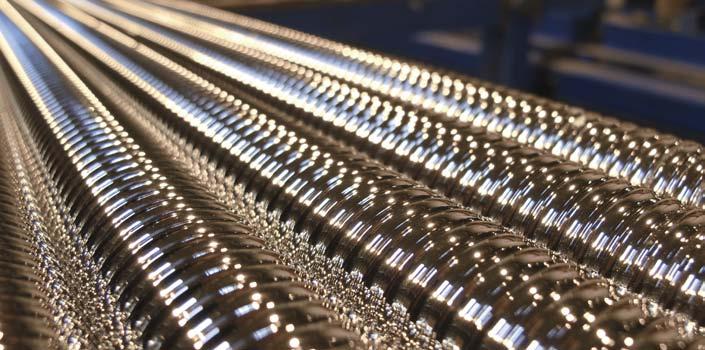
Precision rolled ball screws
|
|
|
- Annabella Carter
- 5 years ago
- Views:
Transcription


1 Precision rolled ball screws


2 Authorised distributors for over 40 manufacturers Acorn Industrial Services Ltd Central distribution centre Divisions Acorn CDC T F E W north@acorn-ind.co.uk Linear Division T F E linear@acorn-ind.co.uk W Couplings Division T F E W couplings@acorn-ind.co.uk Export Division T F E W export@acorn-ind.co.uk Regional Distribution Centres Deeside RDC T F E W deeside@acorn-ind.co.uk East Midlands RDC T F E eastmidlands@acorn-ind.co.uk W Fife RDC T F E W fife@acorn-ind.co.uk Midlands RDC T F E W midlands@acorn-ind.co.uk North East RDC T F E W northeast@acorn-ind.co.uk North West RDC T F E W northwest@acorn-ind.co.uk Scotland RDC T F E W scotland@acorn-ind.co.uk South West RDC T F E W southwest@acorn-ind.co.uk
3 2
4 Contents A Recommendations for selection SKF the knowledge engineering company Product overview Technical concepts Introduction to SKF ball screws... 8 Basic dynamic load carrying capacity (C a ) Nominal fatigue life L Service life Equivalent dynamic load Basic static load carrying capacity (C oa ) Critical rotating speed for screw shafts... 9 Permissible speed limit Screw shaft buckling Lubrication Efficiency and back-driving Axial play and preload Static axial stiffness of a complete assembly Materials, heat treatment and coatings Operating temperature Ball screw support bearings Designing the screw shaft ends Critical applications Working environment B Recommendations for assembly Assembly procedure Storage Alignment Lubrication Removing the nut / assembling the nut on the shaft Wipers assembly Starting-up the screw C Lead precision Manufacturing precision High precision rolled ball screws Lead precision D Product information SD/BD/SH miniature screws SDS/BDS/SHS miniature screws in stainless steel SX/BX universal screws Dedicated flanges for SX/BX nuts SND/BND precision screws, DIN standard PND preloaded screws, DIN standard SN/BN precision screws PN preloaded screws SL/TL long lead screws SLT/TLT rotating nut Shaft end combinations Standard machined ends Ball screw support bearings Examples of customized nuts Manufacturing tolerances Calculation formulae E Service range F Design calculation and inquiry form Designation system G SKF Linear Motion Rollers screws, electromechanical cylinders and guiding solutions
5 SKF the knowledge engineering company From one simple but inspired solution to a misalignment problem in a textile mill in Sweden, and fifteen employees in 1907, SKF has grown to become a global industrial knowledge leader. Over the years we have built on our expertise in bearings, extending it to seals, mechatronics, services and lubrication systems. Our knowledge network includes employees, distributor partners, offices in more than 130 countries, and a growing number of SKF Solution Factories around the world. Research and development We have hands-on experience in over forty industries, based on our employees knowledge of real life conditions. In addition our world-leading experts and university partners who pioneer advanced theoretical research and development in areas including tribology, condition monitoring, asset management and bearing life theory. Our ongoing commitment to research and devel opment helps us keep our customers at the forefront of their industries. Meeting the toughest challenges Our network of knowledge and experience along with our understanding of how our core technologies can be combined helps us create innovative solutions that meet the toughest of challenges. We work closely with our customers throughout the asset life cycle, helping them to profitably and re spon sibly grow their businesses. Working for a sustainable future Since 2005, SKF has worked to reduce the negative environmental impact from our own operations and those of our suppliers. Our continuing technology development intro duced the SKF BeyondZero portfolio of products and services which improve efficiency and reduce energy losses, as well as enable new technol ogies harnessing wind, solar and ocean power. This combined approach helps reduce the environmental impact both in our own oper ations and in our customers. SKF Solution Factories make SKF knowledge and manu facturing expertise available locally, to provide unique solutions and services to our customers. Working with SKF IT and logistics systems and application experts, SKF Authorized Distributors deliver a valuable mix of product and application knowledge to customers worldwide. 4


6 Design and develop Our knowledge your success SKF Life Cycle Management is how we combine our technology platforms and advanced ser vices, and apply them at each stage of the asset life cycle, to help our customers to be more success ful, sustainable and profitable. Specification Maintain and repair SKF Life Cycle Management Operate and monitor Manufacture and test Install and commission D Working closely with you Our objective is to help our customers improve productivity, minimize main tenance, achieve higher energy and resource efficiency, and optimize designs for long service life and reliability. Innovative solutions Whether the application is linear or rotary or a combination of the two, SKF engineers can work with you at each stage of the asset life cycle to improve machine performance by looking at the entire application. This approach doesn t just focus on individual components like bearings or seals. It looks at the whole application to see how each com po nent interacts with the next. Design optimization and verification SKF can work with you to optimize current or new designs with proprietary 3-D modeling software that can also be used as a virtual test rig to confirm the integrity of the design. Bearings SKF is the world leader in the design, development and manufacture of high performance rolling bearings, plain bearings, bearing units and housings. Machinery maintenance Condition monitoring technologies and maintenance services from SKF can help minimize unplanned downtime, improve operational efficiency and reduce maintenance costs. Sealing solutions SKF offers standard seals and custom engineered sealing solutions to increase uptime, improve machine reliability, reduce friction and power losses, and extend lubricant life. Mechatronics SKF fly by wire systems for aircraft and drive bywire systems for off road, agricultural and forklift applications replace heavy, grease or oil consuming mechanical and hydraulic systems. Lubrication solutions From specialized lubricants to state of the art lubrication systems and lubrication management ser vices, lubrication solutions from SKF can help to reduce lubrication related downtime and lubricant consumption. Actuation and motion control With a wide assortment of products from actuators and ball screws to profile rail guides SKF can work with you to solve your most pressing linear system challenges. 5

 16 18 SX/BX 20 5 SX/BX 25 5 10 SX/BX 32 5 10 SX/BX 40 5 10 40 SX/BX 50 10")
 except 10 4 R and")
7 A Recommendations for selection Product overview Screw assembly Type of recirculation Designation Page d 0 P h mm mm SD/BD/SDS/BDS 8 2,5 SD/BD/SDS/BDS 10 2 SD/BD 10 4 SD/BD/SDS/BDS SD/BD/SDS/BDS 14 4 SD/BD/SDS/BDS SD/BD SDS/BDS Internal, by inserts Stainless steel optional 1) SD/BD SH/SHS 6 2 SH 10 3 SH 12,7 12,7 SH SHS External, by integrated tube Stainless steel optional 2) SX/BX 20 5 SX/BX SX/BX SX/BX SX/BX SX/BX SX/BX Internal, by inserts 20 SND/BND/PND SND/BND/PND 20 5 SND/BND/PND SND/BND/PND SND/BND/PND SND/BND/PND SND/BND/PND SND/BND/PND, DIN Internal, by inserts 24 1) except 10 4 R and R 2) 6 2 R only. 6


8 A Screw assembly Type of recirculation Designation Page d 0 P h mm mm SN/BN/PN 16 5 SN/BN/PN 20 5 SN/BN/PN SN/BN/PN SN/BN/PN SN/BN/PN SN/BN/PN Internal, by inserts SN/BN/PN SL/TL SL/TL SLD/TLD SL/TL SL/TL SL/TL SLD/TLD By faces 32 SLT/TLT SLT/TLT SLT/TLT SLT/TLT SLT/TLT rotating nuts By faces 34 FLBU/PLBU/BUF 16 FLBU/PLBU/BUF 20 FLBU/PLBU/BUF 25 FLBU/PLBU/BUF 32 FLBU/PLBU/BUF 40 FLBU/PLBU/BUF 50 FLBU/PLBU/BUF 63 Ball screw support bearings FLBU, PLBU, BUF Complete ball screw assembly with support bearing 44 7

9 A Recommendations for selection Technical concepts Introduction to SKF ball screws This catalogue describes SKF expertise, technology and solutions related to precision rolled ball screws. Thanks to our lengthy experience with manufacturing ball screws and continuous product and process development, SKF provides customers with precision rolled ball screw solutions that fulfil their most demanding applications in terms of efficiency, precision, durability and value. In many cases, these ball screws can replace ground ball screws, offering a similar level of performance and precision at a lower cost. The high quality of SKF rolled ball screws is achieved through our dedicated manufacturing processes, including precision rolling and specific heat-treatment. Ball screws convert rotary motion into linear motion, and vice-versa, and loads are transferred from the screw shaft to the nut through a ball set: in this sense, ball screws relate to general bearing technology. Various types of bearing steel are used to attain the hardness and material fatigue properties required for carrying heavy application loads over extended periods of service. Some bearing concepts such as load ratings, load cycles, nominal and service life, stiffness, speed ratings, lubrication requirements, etc. are explained below to guide customers through the ball screw selection process. Only basic selection parameters are included in this chapter. To make the very best selection of a ball screw, the designer should Life test bench consider critical parameters such as the load cycle, the linear or rotational speed, the rates of acceleration and deceleration, the cycle rate, the environment, the required life, the lead accuracy, the stiffness, and any other special requirements. If in doubt, please consult the SKF ball screw assembly specialists who will assist you in the selection process. Basic dynamic load carrying capacity (C a ) The dynamic load rating capacity is used to compute the nominal fatigue life of ball screws. It results from the axial load, constant in magnitude and direction, which acts along the central axis of the ball screw, resulting in the calculated nominal life as defined by ISO of one million revolutions. With a given combination of nominal diameter and lead, a ball screw s dynamic and static load carrying capacities are determined by the number of ball turns supporting the load. For each product family, the type and number of circuits generate a specific number of ball turns. For example, the SH type nut with external tube recirculation typically presents 2,5 turns of balls within a circuit. The standard SD type nut has 3 circuits covering 0,9 turns each. Nominal fatigue life L 10 Nominal fatigue life is, according to the ISO definition, the life achieved or exceeded by 90% of a large-enough group of apparently identical ball screws, working under identical conditions (alignment, axially and centrally applied load, speed, acceleration, lubrication, temperature and cleanliness). The nominal life of a ball screw is the statistical number of revolutions which the ball screw is capable of reaching before the first signs of material fatigue by flaking occur on one of the rolling surfaces. Service life The actual life achieved by a specific ball screw before it fails is known as service life. Failure is due not only to material fatigue by flaking, but also to inadequate lubrication, wear of the recirculation system, corrosion, contamination and, more generally, loss of the functional characteristics required by the application. Experience acquired with similar applications will help in selecting the right screw to obtain the necessary service life. Structural requirements such as the strength of screw ends and nut attachments should be considered. To attain L 10 life performance, a mean working load of up to 60% of C a (to limit the Hertz pressure at the balls / raceways contacts) and a stroke higher than 4 leads (to avoid false-brinelling which could occur with very short strokes or oscillation movements) are required. Equivalent dynamic load The loads acting on the screw can be calculated according to the laws of mechanics if the external forces (e.g. power transmission, work, rotary and linear inertia forces) are known or can be calculated. It is necessary to calculate the equivalent dynamic load. Radial and moment loads must be taken up by linear bearing systems. It is extremely important to resolve these problems at the earliest possible design stage. These forces are detrimental to the life and the expected performance of the screw ( fig. 1). When the load fluctuates during the working cycle, it is necessary to calculate the equivalent dynamic load: this load is defined as the hypothetical load, constant in magnitude and direction, acting axially and centrally on the screw, which if applied, would have the same influence on the screw life as the actual loads which the screw is subjected to. If misalignment, uneven loading, shocks, etc. cannot be avoided in the application, 8
10 they must be taken in account during the sizing of the ball screw. Their influence on the screw s nominal life can generally be estimated 1). Basic static load carrying capacity (C oa ) Ball screws should be selected considering the basic static load capacity C oa, rather than the basic dynamic load capacity, when they are subjected to continuous or intermittent shock loads while stationary or rotating at very low speed for short periods of time. The permissible load is determined by the permanent deformation caused by the load acting at the contact points. The static load carrying capacity is, according to ISO standards, the purely axially and centrally applied static load which creates, by calculation, a total (rolling element + threaded surface) permanent deformation equal to times the diameter of the rolling element ( fig. 2). A ball screw basic static load rating must be, at a minimum, equal to the product of the maximum axial static load applied and a safety factor s 0. Past experience with similar applications and requirements of running smoothness and noise level will guide the selection of s 0 1). Permissible speed limit The permissible speed limit is the speed which a screw cannot reliably exceed at any time. It is generally the limiting speed of the recirculation system in the nut. It is expressed as the product of maximum rotational speed (in rpm) and the nominal diameter of the screw shaft (expressed in mm). The speed limits quoted in this catalogue ( page 48) are the maximum speeds that may be applied for very short periods of time and with optimized running conditions of alignment, light external load and preload with monitored lubrication. Running a screw continuously at the permissible speed limit may lead to a reduction of the calculated life of the nut mechanism. Important! High speed associated with high load requires a large input torque and yields a relatively short nominal life 1). In the case of high acceleration and deceleration, we recommend either working under a nominal external load or applying a light preload to the nut to avoid internal sliding during reversal of movement. The preload for screws subjected to high velocity must be calculated to ensure that the rolling elements do not slide 1). Excessive preload will create an unacceptable increase in the internal temperature. Lubrication Proper quantities and quality of lubrication must be selected if ball screws are to ope rate correctly and to maximize their service life. Greater care is required for operation at high speed, as the lubricant spread on the surface of the screw shaft may be thrown off by centrifugal forces. It is important to monitor this phenomenon during the first run at high speed and, if necessary, to adapt the frequency of re-lubrication or the flow of lubricant, or to select a lubricant with a different viscosity. Monitoring the steady temperature reached by the nut allows for the optimization of the frequency of re-lubrication or the oil flow rate. SKF SYSTEM 24 automatic lubrication kit can be adapted to most precision rolled ball screws. Yes No Fig. 1 A Critical rotating speed for screw shafts For this calculation, the shaft is equated to a cylinder, with an external diameter equal to the root diameter of the thread. The formulae use a parameter whose value is dictated by the mounting of the screw shaft, whether it is simply supported or fixed. As a general rule, the nut is not considered to be a support of the screw shaft. Because of the potential inaccuracies in the mounting of the screw assembly, a safety factor of 0,8 is applied to the calculated critical speed. Calculations which consider the nut to be a support for the shaft, or which reduce the safety factor, require practical tests and possibly optimization of the design. Screw shaft buckling The column loading of the screw shaft must be checked when it is subjected to dynamic or static compression loading. The maximum permissible compressive load is calculated using the Euler formulae, with a safety factor of 3 to 5, depending on the application. The type of shaft end mounting is critical to select the proper coefficients to be used in the Euler formulae. When the screw shaft has a single diameter along its total length, the root diameter of the threaded shaft is used for the calculation. When the screw comprises different sections with varying diameters, calculation becomes more complex 1). Axials loads Radials loads Moments Load C oa Fig. 2 d 1) SKF can help you make these calculations with consideration to the actual conditions of service. 9
11 A Recommendations for selection Efficiency and back-driving Screw performance primarily depends on the geometry of the contact surfaces and their finish and the helix angle of the thread. It also depends on the working conditions (load, speed, lubrication, preload, alignment, etc.). Direct efficiency is used to define the input torque required to transform the rotation of one component into the translation of the other. Conversely, indirect efficiency is used to define the axial load required to transform the translation of one component into the rotation of the other one. It is also used to define the braking torque required to prevent that rotation. It is safe to assume that ball screws are reversible or back-driveable under almost all circumstances. A braking mechanism (gear reducers or brake) must be part of the design, if back-driving is to be avoided. Preload torque Screws with internal preload exhibit a certain amount of friction torque. This torque still exists when ball screws are not externally loaded. Preload torque is measured with ISO grade 64 oil. Starting torque This is the amount of torque required to overcome the following forces to start rotation: a the total inertia of all moving parts accelerated by the source of power (including rotational and linear movements); b the internal friction of the screw / nut assembly, bearings and associated guiding devices. In general, the torque required to overcome the inertia (a) is greater than the friction torque (b). The friction coefficient of the high efficiency screw when starting moving (µ s ) is estimated to reach up to double the amount of the dynamic coefficient µ, under normal conditions of usage. Axial play and preload SKF products are available with a range of versions of axial play. Standard axial play is intended for transport screws, when the product is not subject to vibrations, high accelerations, and when positioning accuracy under load is not critical (e.g.: SN type). Reduced play (e.g.: SN type with reduced play) and backlash elimination by oversized balls (e.g.: BN type) are recommended to increase assembly precision ( fig. 3). For optimum stiffness and positioning accuracy under load, internally preloaded nuts are recommended (e.g.: PN type) ( fig. 4). When subjected to external loading, preloaded nuts exhibit a much lower elastic deformation than non-preloaded nuts. Preload is the amount of force applied to a set of two half-nuts necessary to either press them together or to push them apart with the purpose of eliminating backlash or increasing the stiffness of the assembly. The preload is measured by the value of the preload torque (see explanations in the previous paragraph). For a given amount of preload (expressed in Newton), the friction torque varies with different types of nuts and with the preloading method. The friction torque due to preload is indicated in product tables. Static axial stiffness of a complete assembly The static axial stiffness of a complete ball screw assembly is the ratio of the external axial load applied to the system and the axial displacement of the face of the nut in relation to the fixed (anchored) end of the screw shaft. Please see calculation formulae ( pages 48 to 49). Nut stiffness: R n When a preload is applied to a split nut, the internal play is eliminated. Additionally, the Hertzian elastic deformation increases with increased preload and increased stiffness. The theoretical elastic deformation at the contact points does not take into account machining inaccuracies, actual sharing of the load between the different contact surfaces, or elasticity of the nut and of the screw shaft. For this reason, the practical stiffness values given in the catalogue are lower than the theoretical values. They are determined by SKF assuming a preload of 8,5% C a for screws with diameter up to 40 mm, and a preload of 7% C a for screws with diameter greater than 40 mm, when applying an external axial load centred on the screw shaft and equal to twice the amount of preload. Shaft stiffness: R s The elastic deformation of the screw shaft is proportional to its length and inversely proportional to the square of the root diameter. According to the relative importance of the screw deformation, an excessive increase of nut preload and of the supporting bearings yields a limited increase of stiffness and noticeably increases the preload torque and therefore the running temperature. Consequently, the preload stated in the catalogue for each screw dimension is optimum and should not be exceeded. Please see calculation formulae ( pages 48 to 49). Fig. 4 Lead + Shift Fig. 3 Nut SN BN Lead Lead Screw 10
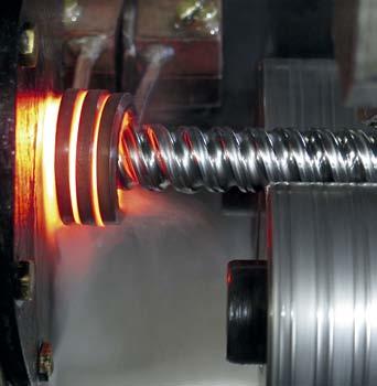
12 Materials, heat treatment and coatings Standard screw shafts are manufactured from carbon steel which is surface hardened by induction. For standard screws, rolling surface hardness is 56 to 60 HRc, depending on diameter (for very small diameter screws, the temperature during the hardening process is slightly lowered to avoid the through-hardening of the screw shaft, therefore resulting in lower surface hardness). Standard nuts are machined from steel which is through-hardened (100 Cr6 NFA or equivalent for diameters 20 mm, and carbon steel for diameters < 20 mm). Most stainless steel screws have a surface hardness ranging from 50 to 58 HRc, depending on the type of stainless steel being used and the screw diameter (note the effect of reduced hardening temperature on small diameter screws, as previously mentioned). The load ratings provided in the catalogue are given for standard screws only. SKF offers various types of surface coating for improved ball screw performance: Manganese phosphate coating is standard for the SX/BX universal nuts. This coating can also be applied to most ranges of precision rolled ball screws to improve the resistance to corrosion Low friction coating or chrome coating are available on request. Please contact SKF. Operating temperature Ball screw support bearings To assist the customer design and machi nery assembly process, SKF has developed a range of support bearings specifically designed for ball screws with nominal diameter starting from 16 mm. These support bearings can easily be mounted on the screw shaft ends, following SKF recommendations for ends machining ( pages 36 to 41). Three types of support bearings available for fixed axial mounting (FLBU type in pages 42 to 43), for fixed radial mounting (PLBU type in pages 44 to 45) and for pure radial support (BUF type in pages 46 to 47), all fitted with SKF premium bearings, greased and sealed for life. SKF stocks these support bearings for quick delivery. Designing the screw shaft ends Generally speaking, when the ends of the screw shaft are specified by the customer s engineering staff, it is their responsibility to check the strength of these ends. However, we offer and recommend a choice of standard machined ends (pages 36 to 41). Please bear in mind that no dimension on the shaft ends can exceed d 0. Otherwise, traces of the root of the thread will appear. If the application requires a shaft end with a smooth surface of diameter greater than d 0, it is advisable to add an additional part attached to the machined shaft end. A minimum shoulder should be sufficient to maintain the bearing inner ring. Please follow bearing mounting recommendations. Working environment Our products have not been developed for use in an explosive environment. Consequently, SKF cannot take any responsibility for the use of ball screws in such applications. A Screws made from standard steel and screws operating under normal loads can operate from 20 to +110 C. Between 110 C and 130 C, SKF must be notified for adaptation of the annealing procedure and for review of the application with hardness below the standard minimum value. Above 130 C, steel adapted to the temperature of the application should be selected (100Cr6, special steel, etc.). Please consult SKF for advice. Operation at high temperatures will lower the steel hardness, alter the thread accuracy, may increase the oxidation of the materials and change the lubricant properties. Critical applications The standard products have been fitted with composite ball recirculation inserts. If the ball screws are used in severe applications, or if the inserts are used to prevent system collapse (especially in the case of vertical applications), optional steel inserts are available. For critical applications, SKF also offers optional safety rings for miniature ball screws, and safety nuts for larger ball screws. In such cases, the customer should consult SKF to define the optimum solution. 1) SKF can help you with these calculations, taking into account the working conditions. 11
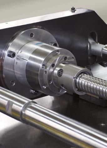
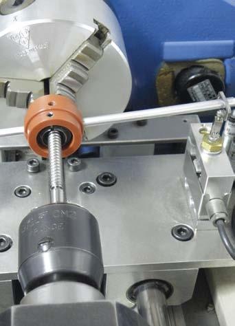
13 B Recommendations for assembly Assembly procedure Ball screw assemblies are precision components and should be handled with care to avoid damaging shocks, contamination or corrosion. Storage Storage location must ensure that ball screw assemblies are not exposed to contamination, shocks, humidity and other detrimental actions. When stored out of the shipping crate, ball screw assemblies must lie on wooden or plastic V-shaped blocks and should not be allowed to bounce. The assembly must not be supported on the shelf by the nut body. During shipping, ball screw assemblies are wrapped in heavy gauge plastic bags, which protect them from foreign material and possible contamination. They should remain wrapped until they are used. Alignment After assembly, any radial load or moment loading on the nut will overload some of the contact surfaces, thus significantly reducing the service life ( fig. 1). SKF linear guidance components should be used to ensure correct alignment and to avoid non-axial loading. The parallelism of the screw shaft with the guiding devices must be checked carefully. If external linear guidance proves impractical, we suggest mounting the nut on trunnions or gimbals, and mounting the screw shaft on selfaligning bearings. Mounting the screw in tension helps to align it properly and eliminates buckling. Lubrication Good lubrication is essential for the proper operation and long term reliability of the ball screw assembly. If necessary, please consult SKF. Before shipping, the complete ball screw assembly is coated with a protective fluid that dries to a film. This protective film is not a lubricant. Depending on the lubricant selected for the application, it may be necessary to remove the protective film before applying the lubricant in order to eliminate any risk of incompatibility. In such cases, we recommend the following procedure: 1 Dip the ball screw assembly into a solvent 2 Shake and rotate the assembly to allow the solvent to penetrate 3 Remove the assembly from the solvent and allow the solvent to drain. Removing the nut / assembling the nut on the shaft Removing the nut from the screw shaft If possible, do not remove the nut from the shaft, especially for preloaded assemblies. If the nut must be removed from the shaft, i.e. for shaft end machining, check the nut orientation before disassembly. Never unscrew the nut from the shaft without a mandrel or sleeve to prevent the balls from falling off the nut ( fig. 6). Once the nut is engaged on the sleeve, use a tie wrap to secure the nut assembly ( fig. 5). Fitting sleeved nut onto screw shaft Sleeved nuts should not be removed from the sleeve until final assembly. 1 Remove the retaining strap ( fig. 5) 2 Check the assembly drawing to confirm the nut orientation 3 Hold the sleeve against the ball track of the screw shaft and smoothly engage the ball nut ( fig. 6) If the sleeve does not cover the diameter next to the ball track (for example, the sleeve bore diameter is smaller than the screw shaft end), then adhesive tape can be used to match the shaft end to the sleeve outer diameter. Otherwise, the sleeve can be held against the unmachined end, if available, with extreme care to prevent the balls from falling off the nut 4 Without using force, completely engage the nut in the screw thread, and run the nut to full engagement on the screw shaft. Wiper assembly If optional wipers have been ordered, please refer to the fitting instructions enclosed with the shipment. Starting up the screw After the assembly has been cleaned, fitted and lubricated, allow the nut to make several full strokes at low speed (< 50 rpm) and light load (not to exceed 5% of the ball screw dynamic carrying capacity) in order to check the proper positioning of the limit switches or reversing mechanism. Then, normal load and speed can be applied. Note: Instructions for most operations such as fitting a nut onto a screw shaft, a wiper onto a nut, etc. are available in separate sheets delivered with the product. Please refer to them before assembling the screw. 12

14 Fig. 5 B Fig. 6 nut screw sleeve Notes 13

15 C Technical data Lead precision Manufacturing precision Generally speaking, the precision indicated defines the lead precision that complies with ISO standards, e.g. G5, G7, etc. ( table 1). Parameters other than lead precision correspond to SKF internal standards, generally based on ISO class 7. If the application requires special tolerances, for example class 5, please specify these requirements in the inquiry. SKF high precision rolled ball screws High technology machinery associated with precise control of the cold forming and me tallurgical processes results in screw production that virtually offers the same accuracy and performance level of ground ball screws, but at a lower cost ( diagram 1). Standard lead precision is G9, which complies with ISO 286-2:1988. SKF production meets G7 lead precision for screw shaft diameters starting from d 0 = 20 mm. On request, SKF can deliver ball screws with G5 lead precision which are in accordance with ISO :2006, defined for positioning screws and matching the lead precision of G5 ground ball screws. Lead precision Lead precision is measured at 20 C on the useful stroke l u. At SKF l u is the threaded length of the shaft minus twice the length l e equal to the screw nominal diameter ( table 1 and fig. 7). Some customer applications require a travel compensation c to account for the effect of operating temperature on the lead precision: Standard case with c = 0 ( fig. 8) Case with specific value of c ( fig. 9). Lead error [µm] ISO standard rolled screws G7 SKF high precision rolled screws G7 SKF high precision rolled screws G5 0 ground screws G Length [mm] Diagram 1 G5 G7 G9 V 300p µm l u e p v up e p v up e p v up mm µm Table (315) (400) (500) (630) (800) (1 000) (1 250) (1 600) (2 000) (2 500) (3 150) (4 000) (5 000) Lead precision measurement
16 Symbols used in figs. 7 to 9 Fig. 7 l u = useful travel l e = excess travel (no lead precision required) l 0 = nominal travel l s = specified travel c = travel compensation (difference between l s and l 0 to be defined by the customer) e p = tolerance over the specified travel V = travel variation (or permissible band width) V 300p = maximum permitted travel variation over 300 mm V up = maximum permitted travel variation over the useful travel l u V 300a = measured travel variation over 300 mm l e Mean travel: the line which fits the curve best by method of least squares v 300a Threaded length l u + l e l 0 [mm] v ua v up l m C V ua = measured travel variation over l u v 300p 300 mm Fig. 8 l e Threaded length l u + l e e p v up e p l 0 [mm] - Fig. 9 l e Threaded length lu + l e l 0 [mm] c v up e p e p l m l s - 15
17 D Product information SD/BD/SH miniature screws Rolled thread miniature ball screw, nut with threaded nose Features Nominal diameter from 6 to 16 mm Lead from 2 to 12,7 mm Recirculation with inserts (SD/BD) or with tube (SH) Optional surface coating on shaft and nut Optional safety ring 1) Optional wipers 2) except 6 2 R 10 3 R. Benefits Excellent repeatability with high positioning accuracy Smooth running Extremely compact nut design with threaded nose for easy assembly Backlash elimination by oversized balls on request (BD designation), over maximum length of mm. Standard SD Recirculation SD/BD Standard SH Customised SD Nominal diameter Lead (right hand) d 0 P h C a C oa Nut Screw Designation Basic load ratings Number Std play Reduced Inertia Grease Weight Mass Inertia Grease dynamic static of circuits of balls play on request mm mm kn mm kgmm 2 cm 3 kg kg/m kgmm 2 /m cm 3 /m 6 2 1,9 2,2 1 2,5 0,05 0,02 7,7 0,1 0,025 0,18 0,7 0,7 SH 6 2 R 8 2,5 2,2 2,7 3 0,07 0,03 1,12 0,1 0,025 0,32 2,1 1,1 SD/BD R ,5 3,6 3 0,07 0,03 1,7 0,1 0,03 0,51 5,2 1,4 SD/BD 10 2 R 3 2,6 3,3 1 2,5 0,07 0,03 2,9 0,3 0,05 0,5 5,1 1,3 SH 10 3 R 4 4,5 5,5 3 0,07 0,03 2,7 0,3 0,04 0,43 3,8 1,3 SD/BD 10 4 R ,9 4,7 3 0,07 0,03 1,5 0,1 0,023 0, ,7 SD/BD 12 2 R 4 4,9 6,6 3 0,07 0,03 7 0,4 0,066 0,71 10,8 1,6 SD/BD 12 4 R 5 4,2 5,4 3 0,07 0,03 5 0,6 0,058 0,71 10,1 1,4 SD/BD 12 5 R 12,7 12,7 6,6 8,9 2 1,5 0,07 0, ,1 0,15 0,71 16,2 1,6 SH 12,7 12,7 R ,1 3 0,07 0,03 8 0,6 0,083 1, ,7 SD/BD 14 4 R ,3 6,2 3 0,07 0,03 9,2 0,6 0,1 1,4 39,7 1,7 SD/BD 16 2 R 5 7,6 10,7 3 0,07 0,03 22,7 0,9 0,135 1,3 33,9 2,1 SD/BD 16 5 R 10 10,7 17,2 2 1,8 0,07 0,03 24,4 1 0,16 1,21 30,7 1,9 SD/BD R 1) Available for 12 4 R 12,7 12,7 R 14 4 R 16 5 R R 2) It is not possible to supply safety ring and wipers in the same nut 16
18 3 3,2 L L 1 D D 1 d 0 d 1 d 2 M 1 2 3) Screw Nut Screw Support bearing Without With Tightening Recommended thrust wiper wiper spanner support bearings d 0 P h D 1 M 1 L L 1 (FACOM) length d 2 d 1 h10 6g ±0,3 max. Recommended support pillow block mm mm mm mm mm mm mm mm ,5 M ,5 126-A , ,5 17,5 M ,5 23,5 7,5 126-A ,3 7, ,5 M ,5 126-A ,3 9, M A ,9 9, M A ,4 8, M , A ,9 11, ,5 M A ,4 11, M A ,3 11,8 12,7 12,7 29,5 M25 1, A , M22 1, A ,9 13, ,5 M25 1, A ,3 15,5 FLBU 16/PLBU 16 BUF ,5 M26 1, A ,7 15,2 FLBU 16/PLBU 16 BUF M26 1, A ,6 15,2 FLBU 16/PLBU 16 BUF 16 17
 Balls are made of stainless steel type X105CrMo17 (similar to AISI 440C) 1) Optional safety ring 2) Optional")
19 D Product information SDS/BDS/SHS miniature screws in stainless steel Rolled thread miniature ball screw, nut with threaded nose Features Nominal diameter from 6 to 16 mm Lead from 2 to 5 mm Standard lead precision G7 and G9 Material for shaft and nut is X30Cr13 (similar to AISI 420) Balls are made of stainless steel type X105CrMo17 (similar to AISI 440C) 1) Optional safety ring 2) Optional wipers 3) except for SHS 6 2 R. Benefits Excellent repeatability with high positioning accuracy Smooth running Extremely compact nut design with threaded nose for easy assembly Backlash elimination by oversized balls on request (BDS designation), over maximum length of mm Suitable for long storage periods before customer usage, or for applications with extremely long service life Adapted for operation in clean environment. Standard SDS Customised SDS Standard SHS SDS BDS Nominal Lead Nut Screw Designation diameter (right Basic load ratings Number Std play Reduced Inertia Grease Weight Mass Inertia Grease hand) dynamic static of circuits of balls play on request d 0 P h C a C oa mm mm kn kn mm mm kgmm 2 cm 3 kg kg/m kgmm 2 /m cm 3 /m 6 2 1,2 1, ,05 0,02 7,7 0,1 0,025 0,18 0,7 0,7 SHS 6 2 R 8 2,5 1,4 1,3 3 0,07 0,03 1,12 0,1 0,025 0,32 2,1 1,1 SDS/BDS 8 2,5 R ,6 1,8 3 0,07 0,03 1,7 0,1 0,03 0,51 5,2 1,4 SDS/BDS 10 2 R ,9 2,3 3 0,07 0,03 1,5 0,1 0,023 0, ,7 SDS/BDS 12 2 R 4 3,1 3,3 3 0,07 0,03 7 0,4 0,066 0,71 10,8 1,6 SDS/BDS 12 4 R 5 2,7 2,7 3 0,07 0,03 5 0,6 0,058 0,71 10,1 1,4 SDS/BDS 12 5 R ,8 4,6 3 0,07 0,03 8 0,6 0,083 1, ,7 SDS/BDS 14 4 R ,1 3,1 3 0,07 0,03 9,2 0,6 0,1 1,4 39,7 1,7 SDS/BDS 16 2 R 5 4,8 5,4 3 0,07 0,03 22,7 0,9 0,135 1,3 33,9 2,1 SDS/BDS 16 5 R 1) Except for size SDS/BDS 16 5 R using steel type 100 Cr6 (similar to AISI 52100) 2) Available for 12 4 R 14 4 R 16 5 R 3) It is not possible to supply safety ring and wipers in the same nut 18
20 3 3,2 L L 1 D D 1 d 0 d 1 d 2 M 1 2 3) Screw Nut Screw Support bearing Without With Tightening Recommended thrust wiper wiper spanner support bearings d 0 P h D 1 M 1 L L 1 (FACOM) length d 2 d 1 h10 6g ±0,3 max. Recommended support pillow block mm mm mm mm mm mm mm mm ,5 M ,5 126-A , ,5 17,5 M ,5 23,5 7,5 126-A ,3 7, ,5 M ,5 126-A ,3 9, M ,5 23, A ,9 11, ,5 M A ,4 11, M A ,3 11, M22 1, A ,9 13, ,5 M25 1, A ,3 15,5 FLBU 16/PLBU 16 4) BUF 16 4) ,5 M26 1, A ,7 15,2 FLBU 16/PLBU 16 4) BUF 16 4) 4) Support bearings with standard steel 19
21 D Product information SX/BX universal screws Rolled thread ball screw with recirculation through inserts, nut with threaded nose Features Nominal diameter from 20 to 63 mm Lead from 5 to 40 mm Standard composite recirculation inserts Optional steel recirculation inserts Lubrication hole for grease nipple or for SKF SYSTEM 24 automatic lubrication kit Phosphate coating on nut Optional shaft surface coating Optional safety nuts. Please contact SKF for selection and usage of this option Optional nut flanges ( pages 22 to 23) Optional wipers. Standard Recirculation Benefits Minimum nut outside diameter and threaded nose for easy assembly Nut design well suited and economical for transport screw applications Optional steel recirculation inserts can act as a safety device for severe or vertical applications. Please contact SKF for such applications Backlash elimination by oversized balls on request (BX designation) for applications with vibrations / changes of direction, over maximum length of mm. Customised SX BX Nominal Lead Nut Screw Designation diameter (right Basic load ratings Number Std play Reduced Preload Inertia Grease Weight Mass Inertia Grease hand) dynamic static of circuits of balls play on request torque zero play d 0 P h C a C oa T pr mm mm kn mm Nm kgmm 2 cm 3 kg kg/m kgmm 2 /m cm 3 /m ,8 4 0,1 0,05 0,1 60 1,3 0, ,7 SX/BX 20 5 R ,8 5 0,1 0,05 0, ,5 0,39 3, ,4 SX/BX 25 5 R 10 23, ,12 0,08 0, ,6 0,4 3, ,2 SX/BX R ,6 5 0,1 0,05 0, ,6 0,48 5, ,4 SX/BX 32 5 R 10 27, ,12 0,08 0, ,9 0,77 5, ,7 SX/BX R ,3 65,6 5 0,1 0,05 0, ,3 0, ,6 SX/BX 40 5 R/L 10 61,5 124,1 5 0,12 0,08 0, ,4 1,25 8, SX/BX R 40 31,3 72,9 2 1,9 0,1 0,05 0, ,4 1,6 8, ,2 SX/BX R ,4 188,8 6 0,12 0,08 1, ,9 2,4 13, ,3 SX/BX R ,2 248,3 6 0,12 0,08 1, ,4 3, ,1 SX/BX R 20
22 8 L L 2 L 1 D 1 d 0 d 1 d 2 M 1 D L 4 M 2 Screw Nut Screw Support bearing Tightening spanner Recommended thrust support bearings d 0 P h D 1 M 1 L L 1 L 2 L 4 M2 1) length d 2 d 1 js13 6g max. Recommended support pillow block mm mm mm mm M35 1, M6 1 HN ,7 19,4 PLBU 20/FLBU 20 2) BUF M40 1, M6 1 HN ,7 24,6 PLBU 25/FLBU 25 BUF M40 1, M6 1 HN ,5 24,6 PLBU 25/FLBU 25 BUF M48 1, M6 1 HN ,7 31,6 PLBU 32/FLBU 32 BUF M48 1, M6 1 HN ,8 32 PLBU 32/FLBU 32/FLRBU 3 3) BUF M56 1, M6 1 HN ,7 39,6 PLBU 40/FLBU 40 BUF M M8 1 HN ,4 PLBU 40/FLBU 40/FLRBU 4 3) BUF M ,6 M8 1 HN ,2 38,3 PLBU 40/FLBU 40 BUF M M8 1 HN ,7 PLBU 50/FLBU 50/FLRBU 5 3) BUF M M8 1 HN ,8 PLBU 63/FLBU 63 BUF 63 1) Threaded lubrication hole M2 indexed to ISO thread M 1 2) For high load application, please contact SKF 3) For high load application, use FLRBU type. Please refer to roller screws catalogue for end shaft and support bearings definitions 21
23 D Product information Dedicated flanges for SX/BX nuts G J SX nut with round flange (FHRF) L 1 H L SX nut with square flange (FHSF) L L 1 J 1 N J H L 1 /2 D 1 H 2 H 3 SX nut with trunnions flange (FHTF) L L 1 H 1 22
24 Nominal diameter Lead Dimensions Designation d 0 P h L L 1 G H J h14 h12 js12 mm mm mm M FHRF M FHRF M FHRF M FHRF M FHRF M FHRF M FHRF M FHRF M FHRF M FHRF 63 D Nominal diameter Lead Dimensions Designation d 0 P h L L 1 H J J 1 N h14 h14 js12 mm mm mm ,6 6,6 FHSF ,5 9 FHSF ,5 9 FHSF ,8 9 FHSF ,8 9 FHSF FHSF ,3 13 FHSF ,3 13 FHSF FHSF FHSF 63 Nominal diameter Lead Dimensions Designation Glycodur designation d 0 P h L L 1 H 1 H 2 H 3 D 1 GLY PG js16 h12 h12 h8 mm mm mm FHTF A FHTF A FHTF A FHTF A FHTF A FHTF A ,5 27, FHTF A ,5 27, FHTF A FHTF A FHTF A 23
")
25 D Product information SND/BND precision screws, DIN standard Rolled thread ball screw with recirculation through inserts, DIN nut Features Nominal diameter from 16 to 63 mm Lead from 5 to 10 mm Standard composite recirculation inserts Optional steel recirculation inserts Standard lead precision G5, G7 and G9 Nut ground outside diameter / flange face Precision ground nut thread 1) Lubrication hole for grease nipple or for SKF SYSTEM 24 automatic lubrication kit Optional surface coating on shaft and nut Optional safety nuts. Please contact SKF for selection and usage of this option Optional wipers. Standard Recirculation Benefits Compact nut / integral flange for easy assembly Design well suited for positioning screws. G5 lead precision of ground ball screws Optional steel recirculation inserts can act as a safety device for severe or vertical applications. Please contact SKF for such applications Backlash elimination by oversized balls on request (BND designation), over maximum length of mm. Assembly with flanged support bearing SND BND Nominal Lead Nut Screw Designation diameter (right Basic load ratings Number Std Reduced Preload Inertia Grease Weight Mass Inertia Grease hand) dynamic static of circuits of balls play play on request torque zero play d 0 P h C a C oa T pr mm mm kn mm Nm kgmm 2 cm 3 kg kg/m kgmm 2 /m cm 3 /m ,8 10,7 3 0,08 0,05 0, ,9 0,17 1,3 33 2,1 SND/BND 16 5 R 10 10,7 17,2 2 1,8 0,07 0,03 0, ,6 0,18 1,21 30,7 2,1 SND/BND R ,3 17,9 3 0,1 0,05 0, ,1 0, ,7 SND/BND 20 5 R ,7 22,7 3 0,1 0,05 0, ,6 0,29 3, ,4 SND/BND 25 5 R 10 24, ,12 0,08 0, ,5 0,38 3, ,2 SND/BND R ,3 4 0,1 0,05 0, ,1 0,54 5, ,5 SND/BND 32 5 R 10 21, ,12 0,08 0, ,6 0,58 5, ,2 SND/BND R ,6 65,6 5 0,1 0,05 0, ,1 0, ,6 SND/BND 40 5 R/L 10 63,3 124,1 5 0,12 0,08 0, ,7 1,3 8, ,1 SND/BND R ,3 157,3 5 0,12 0,08 0, ,1 1,8 13, ,5 SND/BND R ,5 206,9 5 0,12 0,08 1, ,1 2, ,4 SND/BND R 1) Except R: nut thread is not ground 24
26 L 8 M6 1-6H long 8 22,5 D 4 L 7 /2 0,8 (6 ) D 5 IT11 d 0 d 1 d 2 D 1-0,2-0,5 D 1 D 6 M8 1-6H long Design 1 L 8 30 D 4 D 0,8 (8 ) D 5 IT11 L 1 L 7 L Design 2 Screw Nut Screw Support bearing Recommended thrust support bearings d 0 P h D 1 D 4 Design D 5 D 6 L L 1 L 7 L 8 length d 2 d 1 g6 H13 h13 h13 max. Recommended support pillow block mm mm mm mm , , ,7 15,2 FLBU 16/PLBU 16 BUF , ,6 15,2 FLBU 16/PLBU 16 BUF , , ,7 19,4 PLBU 20/FLBU 20 BUF , , ,7 24,6 PLBU 25/FLBU 25 BUF , ,5 24,6 PLBU 25/FLBU 25 BUF , ,7 31,6 PLBU 32/FLBU 32 BUF ,8 32 PLBU 32/FLBU 32 BUF , ,7 39,6 PLBU 40/FLBU 40 BUF ,4 PLBU 40/FLBU 40/FLRBU 4 2) BUF ,7 PLBU 50/FLBU 50/FLRBU 5 2) BUF ,8 PLBU 63/FLBU 63 BUF 63 2) For high load application, use FLRBU type. Please refer to roller screws catalogue for end shaft and support bearings definitions 25
 Standard")
27 D Product information PND preloaded screws, DIN standard Rolled thread ball screw with recirculation through inserts, DIN nut Features Nominal diameter from 16 to 63 mm Lead from 5 to 10 mm Standard composite recirculation inserts Optional steel recirculation inserts Standard lead precision G5, G7 and G9 Nut ground outside diameter / flange face Precision ground nut thread 1) Standard preload 7% to 8,5% of ball screw C a value, depending on ball screw size Lubrication hole for grease nipple or for SKF SYSTEM 24 automatic lubrication kit Optional surface coating on shaft and nut Optional safety nuts. Please contact SKF for selection and usage of this option Optional wipers. Standard Recirculation Benefits Compact nut / integral flange for easy assembly One-piece nut 1) with internal preload for compactness and optimum rigidity Design well suited for positioning screws. G5 lead precision of ground ball screws Optional steel recirculation inserts can act as a safety device for severe or vertical applications. Please contact SKF for such applications. Assembly with pillow block PND Nominal Lead Nut Screw Designation diameter (right Basic load ratings Number Preload Stiffness Inertia Grease Weight Mass Inertia Grease hand) dynamic static of circuits of balls torque average d 0 P h C a C oa T pr R n mm mm kn Nm N/µm kgmm 2 cm 3 kg kg/m kgmm 2 /m cm 3 /m ,5 7, , ,19 1,3 33 2,1 PND 16 5 R 10 10,7 17, ,8 0, ,7 0,28 1,21 30,7 1,9 PND R 1) , , ,3 0, ,7 PND 20 5 R ,7 22, , ,4 3, ,4 PND 25 5 R 10 13,3 19, , ,5 0,53 3, ,2 PND R , , ,2 0,715 5, ,2 PND 32 5 R 10 21, , ,6 0,81 5, ,1 PND R ,6 65, , ,8 1, ,5 PND 40 5 R/L 10 52,2 99, , ,5 1,8 8, ,9 PND R ,3 157, , ,5 2,6 13, ,9 PND R ,5 206, , ,8 3, ,9 PND R 1) Except R: nut thread is not ground, double nut design 26
28 L 8 M6 1-6H long 8 22,5 D 4 L 7 /2 0,8 (6 ) D 5 IT11 d 0 d 1 d 2-0,2-0,5 D 1 D 1 D 6 M8 1-6H long Design 1 L 8 30 D 4 D 0,8 (8 ) D 5 IT11 L 1 L 7 L Design 2 Screw Nut Screw Support bearing Recommended thrust support bearings d 0 P h D 1 D 4 Design D 5 D 6 L L 1 L 7 L 8 length d 2 d 1 g6 js12 H13 h13 h13 max. Recommended support pillow block mm mm mm , ,7 15,2 FLBU 16/PLBU 16 BUF , ,6 15,2 FLBU 16/PLBU 16 BUF , ,7 19,4 PLBU 20/FLBU 20 BUF , ,7 24,6 PLBU 25/FLBU 25 BUF , ,5 24,6 PLBU 25/FLBU 25 BUF ,7 31,6 PLBU 32/FLBU 32 BUF ,8 32 PLBU 32/FLBU 32 BUF ,7 39,6 PLBU 40/FLBU 40 BUF ,4 PLBU 40/FLBU 40/FLRBU 4 2) BUF ,7 PLBU 50/FLBU 50/FLRBU 5 2) BUF ,8 PLBU 63/FLBU 63 BUF 63 2) For high load application, use FLRBU type. Please refer to roller screws catalogue for end shaft and support bearings definitions 27
29 D Product information SN/BN precision screws Rolled thread ball screw with recirculation through inserts, cylindrical flange Features Nominal diameter from 16 to 63 mm Lead from 5 to 10 mm Standard composite recirculation inserts Optional steel recirculation inserts Standard lead precision G5, G7 and G9 Nut ground outside diameter / flange face Precision ground nut thread Lubrication hole for grease nipple or for SKF SYSTEM 24 automatic lubrication kit Optional surface coating on shaft and nut Optional safety nuts. Please contact SKF for selection and usage of this option Optional wipers. Standard Recirculation Benefits Economical compact nut / integral flange for easy assembly Design well suited for positioning screws. G5 lead precision of ground ball screws Optional steel recirculation inserts can act as a safety device for severe or vertical applications. Please contact SKF for such applications Backlash elimination by oversized balls on request (BN designation), over maximum length of mm. Customised SN BN Nominal Lead Nut Screw Designation diameter (right Basic load ratings Number Std Reduced Preload Inertia Grease Weight Mass Inertia Grease hand) dynamic static of circuits of balls play play on request torque zero play d 0 P h C a C oa T pr mm mm kn mm Nm kgmm 2 cm 3 kg kg/m kgmm 2 /m cm 3 /m ,8 10,7 3 0,08 0,05 0, ,9 0,18 1,3 33 2,1 SN/BN 16 5 R ,3 17,9 3 0,1 0,05 0, ,2 0, ,7 SN/BN 20 5 R ,7 22,7 3 0,1 0,05 0, ,6 0,28 3, ,4 SN/BN 25 5 R 10 24, ,12 0,08 0, ,5 0,53 3, ,2 SN/BN R ,3 4 0,1 0,05 0, ,1 0,4 5, ,5 SN/BN 32 5 R 10 21, ,12 0,08 0, ,6 0,83 5, ,2 SN/BN R ,6 65,6 5 0,1 0,05 0, ,1 0, ,6 SN/BN 40 5 R/L 10 63,3 124,1 5 0,12 0,08 0, ,7 1,4 8, ,1 SN/BN R ,3 157,3 5 0,12 0,08 0, ,1 1,8 13, ,5 SN/BN R ,5 206,9 5 0,12 0,08 1, ,1 2, ,4 SN/BN R 28
30 60 L 7 /2 30 M 2 L 10 0,8 D 4 d 0 d 1 d 2-0,2-0,5 D 1 D 1 D 6 D 0,8 (6x) D 5 IT11 L 1 L 7 L Screw Nut Screw Support bearing Recommended thrust support bearings d 0 P h D 1 D 4 D 5 D 6 L L 1 L 7 L 10 M 2 length d 2 d 1 g6 H13 h13 6H max. Recommended support pillow block mm mm mm , M ,7 15,2 FLBU 16 / PLBU 16 BUF , M ,7 19,4 PLBU 20 / FLBU 20 BUF , M ,7 24,6 PLBU 25 / FLBU 25 BUF M ,5 24,6 PLBU 25 / FLBU 25 BUF , M ,7 31,6 PLBU 32 / FLBU 32 BUF M ,8 32 PLBU 32 / FLBU 32 BUF , M ,7 39,6 PLBU 40 / FLBU 40 BUF M ,4 PLBU 40 / FLBU 40 / FLRBU 4 1) BUF x M8x ,7 PLBU 50 / FLBU 50 / FLRBU 5 1) BUF x M8x ,8 PLBU 63 / FLBU 63 BUF 63 1) For high load application, use FLRBU type. Please refer to roller screws catalogue for end shaft and support bearings definitions 29
31 D Product information PN preloaded screws Rolled thread ball screw with recirculation through inserts, cylindrical flange Features Nominal diameter from 16 to 63 mm Lead from 5 to 10 mm Standard composite recirculation inserts Optional steel recirculation inserts Standard lead precision G5, G7 and G9 Nut ground outside diameter / flange face Precision ground nut thread Standard preload 7% to 8,5% of ball screw C a value, depending on ball screw size Lubrication hole for grease nipple or for SKF SYSTEM 24 automatic lubrication kit Optional surface coating on shaft and nut Optional safety nuts. Please contact SKF for selection and usage of this option Optional wipers. Standard Recirculation Benefits Economical compact nut / integral flange for easy assembly One-piece nut with internal preload for compactness and optimum rigidity Design well suited for positioning screws. G5 lead precision of ground ball screws Optional steel recirculation inserts can act as a safety device for severe or vertical applications. Please contact SKF for such applications. Customised PN Nominal Lead Nut Screw Designation diameter (right Basic load ratings Number Preload Stiffness Inertia Grease Weight Mass Inertia Grease hand) dynamic static of circuits of balls torque average d 0 P h C a C oa T pr R n mm mm kn Nm N/µm kgmm 2 cm 3 kg kg/m kgmm 2 /m cm 3 /m ,5 7, , ,19 1,3 33 2,1 PN 16 5 R , , ,1 0, ,4 PN 20 5 R ,7 22, , ,1 0,39 3, ,4 PN 25 5 R 10 13,3 19, , ,1 0,53 3, ,8 PN R , , ,2 0,5 5, ,4 PN 32 5 R 10 21, , ,6 1,13 5, ,1 PN R ,6 65, , ,8 0, ,5 PN 40 5 R/L 10 52,2 99, , ,6 1,8 8, ,9 PN R ,3 157, , ,5 2,6 13, ,9 PN R ,5 206, , ,8 3, ,9 PN R 30
32 60 L 7 /2 30 M 2 L 10 0,8 D 4 d 0 d 1 d 2-0,2-0,5 D 1 D 1 D 6 D 0,8 (6x) D 5 IT11 L 1 L 7 L Screw Nut Screw Support bearing Recommended thrust support bearings d 0 P h D 1 D 4 D 5 D 6 L L 1 L 7 L 10 M 2 length d 2 d 1 g6 js12 H13 h13 6H max. Recommended support pillow block mm mm mm , M ,7 15,2 FLBU 16/PLBU 16 BUF , M ,7 19,4 PLBU 20/FLBU 20 BUF , M ,7 24,6 PLBU 25/FLBU 25 BUF , M ,5 24,6 PLBU 25/FLBU 25 BUF , M ,7 31,6 PLBU 32/FLBU 32 BUF M ,8 32 PLBU 32/FLBU 32 BUF , M ,7 39,6 PLBU 40/FLBU 40 BUF M ,4 PLBU 40/FLBU 40/FLRBU 4 1) BUF M ,7 PLBU 50/FLBU 50/FLRBU 5 1) BUF M ,8 PLBU 63/FLBU 63 BUF 63 1) For high load application, use FLRBU type. Please refer to roller screws catalogue for end shaft and support bearings definitions 31
33 D Product information SL/TL long lead screws Rolled thread ball screw for high linear speed Features Nominal diameter from 25 to 50 mm Lead from 20 to 50 mm Lubrication hole for grease nipple or for SKF SYSTEM 24 automatic lubrication kit Standard protection at each end of the nut with composite wipers integrated into recirculation caps (NOWPR) Optional double protection at each end of the nut with additional brush wipers fitted into recirculation caps (WPR) Optional surface coating on shaft and nut Optional safety nuts. Please contact SKF for selection and usage of this option. Benefits High rotational speed up to nd 0 = , resulting in high linear speed up to 110 m/min Nut design well suited for transport and positioning screw applications requiring high velocity such as woodworking, some functions in plastic injection presses, pick & place, etc. Backlash elimination (TL designation). Standard Customised Recirculation Optional double protection Nominal Lead Nut Screw Designation diameter (right SL (with play) TL (with backlash elimination) hand) Basic load ratings Std Basic load ratings Preload Number Inertia Grease Weight Mass Inertia Grease dynamic static play dynamic static torque zero play of circuits of balls d 0 P h C a C oa C a C oa T pr mm mm kn mm kn Nm kgmm 2 cm 3 kg kg/m kgmm 2 /m cm 3 /m ,8 51,5 0,08 12,6 25,8 0,04-0,36 4 1, ,57 3, ,4 SL/TL R 25 22,3 50,6 0,08 12,3 25,3 0,04-0,36 4 1, ,6 0,66 3, ,3 SL/TL R ,4 65,2 0, ,6 0,05-0,45 4 1, ,4 0,7 5, ,4 SL/TL R 32 26,1 69,3 0,08 14,4 34,7 0,05-0,50 4 1, ,5 0,7 5, ,3 SL/TL R 32 26,1 69,3 0,08 14,4 34,7 0,05-0,50 4 1, ,5 0,7 5, ,3 SLD/TLD R 40 12,6 29,8 0,08 6,9 14,9 0,05-0,50 4 0, ,65 4, ,4 SL/TL R ,3 128,8 0,08 22,8 64,4 0,05-0,55 4 2, ,6 1,2 8, ,5 SL/TL R 40 51,7 130,5 0,1 28,5 65,3 0,05-0,55 4 1, ,5 2,4 8, ,2 SL/TL R ,9 235,1 0,12 51,2 117,6 0,1-0,9 4 1, ,4 3,3 13, ,4 SL/TL R 32
34 L M 2 L 3 L 7/2 L 7 L 1 D 4 0,8 (6 ) D 5 IT11-0,2-0,5 D 1 D 6-0,2 D 1 d 0 d 1 d 2-0,5 D 1 Design 1 L 8 M6 1-6H long 8 22,5 D 0,8 (6 ) D 5 IT11 D 4 90 Design 2 Screw Nut Screw Support bearing Recommended thrust support bearings d 0 P h D 1 D 4 Design D 5 D 6 L L 1 L 3 L 7 L 8 L 10 M 2 length d 2 d 1 g9 js12 H13 h13 max. Recommended support pillow block mm mm mm mm , , ,6 15 N / A 8 M ,7 24,3 PLBU 25/FLBU 25 BUF , , ,7 15 N / A 8 M ,5 24,4 PLBU 25/FLBU 25 BUF , , ,9 15 N / A 8 M ,5 30 PLBU 32/FLBU 32/FLRBU3 1) BUF , , N / A 8 M ,4 31,1 PLBU 32/FLBU 32/FLRBU3 1) BUF g , M ,4 31,1 PLBU 32/FLBU 32/FLRBU3 1) BUF g , , ,2 15 N / A 8 M ,9 29,6 PLBU 32/FLBU 32 BUF , N / A 8 M ,2 37,7 PLBU 40/FLBU 40 BUF , ,6 25 N / A 10 M ,2 38,3 PLBU 40/FLBU 40/FLRBU 4 1) BUF ,5 25 N / A 10 M ,5 49,1 PLBU 50/FLBU 50/FLRBU 5 1) BUF 50 1) For high load application, use FLRBU type. Please refer to roller screws catalogue for end shaft and support bearings definitions 33

35 D Product information SLT/TLT rotating nut Long lead rolled ball screw with rotating nut Concept The main purpose of this solution is to minimize the inertia phenomenon associated with long rotating shafts. The long lead screw shaft is rigidly fixed to the machine frame. The ball nut, rotating inside a bearing housing and driven via a tension belt, moves along the screw shaft. The customers are responsible for the sourcing and assembly of the electric motor, belt, pulleys and frame holding the bearing housing. Features Nominal diameter from 25 to 50 mm Lead from 20 to 50 mm 72 series angular contact bearings are directly mounted on the nut outer diameter Bearings are preloaded in back-to-back arrangement in order to fully support the moment created by the belt tension 2 Nilos rings protect the bearings against pollution and permit lubrication for life Brush wipers are mounted at each end of the nut in the standard configuration for better protection against contamination The ball screw assembly is lubricated through a nipple mounted on the housing external diameter in the standard version Standard grease is SKF LGMT2. Other lubricants are available on request. Nominal Lead Ball screw capacities Bearing Rotating nut Designation diameter (right SL TL hand) Basic load ratings Basic load ratings Basic load ratings Max transmissible Max transmissible Inertia with pulley Mass d 0 P h C a C oa C a C oa C a C oa torque axial load support mm mm kn kn Nm kn kgmm 2 kg ,2 97,0 21,6 48,5 61, , ,5 SLT/TLT R 25 33,2 80,4 18,3 40,2 61, , ,6 SLT/TLT R ,6 141,8 27,3 70, , ,2 SLT/TLT R 32 32,2 88,6 17,7 44, , , ,1 SLT/TLT R 40 25,3 67,0 13,9 33, , , ,1 SLT/TLT R ,2 176,5 29,8 88,3 93,6 91, ,5 SLT/TLT R 40 51,7 130,5 28,5 65, , ,4 SLT/TLT R ,9 235,1 51,2 117, ,5 SLT/TLT R 34
36 Benefits High rotational speed up to nd 0 = , resulting in high linear speed up to 110 m/min Compact, easy and simple solution to incorporate into application Fixed screw shaft for simplified mounting into application Inertia is considerably reduced, for example: kgmm 2 instead of kgmm 2 for a screw shaft with 4,5 m stroke Lower motor power requirements resul ting from lower system inertia Backlash elimination (TLT designation). Screw Dimensions d 0 P h L L 1 L 2 L 3 L 4 L 5 L 6 L 7 L 8 L 9 mm , ,4 19,9 74 2,9 16,9 12, , ,4 19,9 74 2, , ,9 20 3,8 27,5 89 2,2 17, ,8 20 3,8 27,5 89 2,2 11, ,9 20 3,8 27,5 89 2,2 10, ,7 20 9,3 22,5 85 4,7 17, ,6 47 8, ,8 11, , ,5 25, ,5 23,5 15, D L 8 L 7 L 2 L 9 L 1 L 6 0,8 Z 2 x H 2 Z 1 x H 1 D 3 D 2 D 1 D 7 D 6 D 5 D 4 R H 3 0,8 R L L 5 3 L 4 L J 2 J 1 Screw Dimensions d 0 P h D 1 D 2 D 3 D 4 D 5 D 6 D 7 R J 1 J 2 Z 1 H 1 Z 2 H 2 H 3 h8 g6 max. useful depth mm , , Ø9 6 M6 20 M , , Ø9 6 M6 20 M , , Ø9 6 M6 20 M , , Ø9 6 M6 20 M , , Ø9 6 M6 20 M , Ø9 6 M6 20 M N/A 72 1, Ø9 6 M6 20 M , Ø11 6 M8 30 M8 1 All tolerances js13 if not specified. 35
37 D Product information Shaft end combinations In the ordering code, shaft ends machining is defined by: One letter for nominal diameter d 0 < 16 mm Two letters for nominal diameter d 0 16 mm, detailing the combination of two machined ends ( designation system page 54) Machined ends are detailed for nominal diameter < 16 mm ( page 37) Machined ends are detailed for nominal diameter 16 mm ( pages 38 to 41). Diameter < 16 mm Diameter 16 mm Order code Two machined ends Order code Two machined ends A (without length indication) A (+ length) B F 1) G 1) H J cut only cut + annealed AA (without length indication) BA FA 1) GA 1) HA JA cut only 1A + 2A 2A + 2A 2A + 3A 2A + 4A 2A + 5A S, SA and UA end machining types *) S and SA: end is machined to thread root diameter d 2. It is available for all screw shaft nominal diameters ( fig. 10) *) UA: end is machined to diameter d 3 under induction hardened layer. Any length can be used. UA end machining is available for ball screws with nominal diameter d 0 starting from 16 mm ( fig. 10). M S *) (+ length) K Z end machined to root diameter d 2, any length keyway end machined according to customer drawing on request MA SA *) (+ length) UA *) (+ length) K Z 3A + 5A end machined to root diameter d 2, any length end machined to diameter d 3 under induction hardening, any length keyway end machined according to customer drawing on request 1) Attention! This mounting requires the greatest care. Please contact SKF. Dimensions Dimensions d 2 d 3 d 2 d 3 mm mm mm mm Fig , ,7 12, ,7 6,3 8,3 7,8 7,4 9,9 9,4 9,3 10,2 11, ,7 20,5 21,7 21,5 28,7 27,8 27,4 28,4 26,9 36,7 34,0 35,1 34, d 2 d ,3 12,7 12,6 16, ,0 43,4 57,
38 Standard end machining for nominal diameter < 16 mm For SD/BD/SH SDS/BDS/SHS undercut e b d 0 d 5 G d 4 t t b a d 7 G1 B 1 (B 2 ) B 4 ch 45 ch 45 a N 9 - S A j A D Type 1 Type 2 Keyway on request B 5 m d 6 B 5 m d 6 undercut undercut undercut G d 4 d 4 d 5 d 4 t b a d 7 B 1 G1 ch 45 t B 3 ch 45 t B 3 ch 45 ch 45 B 6 (B 2 ) Type 3 Type 4 Type 5 Dimensions d 0 d 5 d 4 1) B 1 B 2 B 3 B 4 B 5 B 6 G G 1 m d 6 ch b a d 7 a b e j S Keyway h7 js7 js12 js12 js12 H11 js12 6g +0,14 h11/ h11 N9 +0,5 DIN h12 0 mm ,4 17 M4 0,7 7 0,5 3,8 0,5 1,2 2, ,6 19 M5 0,8 7,2 0,7 4,8 0,5 1,2 3, ,7 21 M6 1 7,5 0,8 5,7 0,5 1,5 4,5 12/12, ,8 22 M8 1 12,5 0,9 7,6 0,5 1,5 6, ,8 0,1 A M10 1,5 13,3 1,1 9,6 0,5 2,3 7, ,8 0,1 A ) For applications with radial loads on support bearings, please consult SKF for best selection of tolerance on diameter d 4 37
39 D Product information Standard end machining for shaft nominal diameter 16 mm For SD/BD SDS/BDS SX/BX SND/BND/PND SN/BN/PN Standard shaft ends for ball screws with nominal diameter d 0 16 mm have been developed to fit with the SKF support bearings FLBU, PLBU and BUF. Support bearing FLBU PLBU BUF Machined end type 2A or 3A 2A or 3A 4A or 5A For these types of machined ends, the maximum permissible dynamic load is 75% of the ball screw dynamic load carrying capacity. Type 1A t d 0 undercut d 5 G d 4 b a d 7 ch 1 45 ch 1 45 t G1 B 1 (B 2 ) B 4 Type 2A Size d 0 d 5 d 1) 4 d 11 d 12 B 1 B 2 B 3 B 4 B 5 B 6 B 7 d 8 h7 h6 h6 h7 js12 js12 js12 H11 js12 mm , ,5 25 1) , ) ,5 21,7 40 1) ,5 67 4,5 33,5 50 1) ,5 67 4,5 35, , ) For applications with radial loads on support bearings, please consult SKF for best selection of tolerance on diameter d 4 38
40 undercut t B 5 B 7 d 8 m d 6 undercut G d 4 d 12 d 11 t b a d 7 B 1 G1 ch 1 45 ch 2 45 B 3 ch 1 45 ch 1 45 B6 D Type 3A Type 5A t B 7 d 8 B 5 m d 6 undercut // // b d 11 ch 2 45 B 3 ch 1 45 a N 9 Type 4A Keyway on request Size Keyway to DIN 6885 a N9 l b d 0 G G 1 m d 6 ch 1 ch 2 b a d 7 6g +0,14 h11 h12 fixed end fixed end 0 h11 (type 2A) (type 5A) mm 16 M10 0, ,1 9,6 0,5 0,5 1,2 8,8 A A M ,1 9,6 0,5 0,5 1,5 10,5 A A M ,1 16,2 0,5 0,5 1,5 15,5 A A M ,1 16,2 0,5 0,5 1,5 18,5 A A M30 1,5 25 1,6 28,6 1 0,5 2,3 27,8 A A M35 1,5 27 1,6 28,6 1 0,5 2,3 32,8 A A M50 1,5 32 1,85 42,5 1,5 1 2,3 47,8 A A
41 D Product information Standard end machining for SL/TL only Standard shaft ends for SL/TL ball screws have been developed to fit with the SKF support bearings FLBU, PLBU and BUF. For the SL/TL long lead screw, an additional centering diameter, part of the threaded length, will be machined at both ends of the screw shaft to facilitate the nut assembly. Support bearing FLBU PLBU BUF Machined end type 2A or 3A 2A or 3A 4A or 5A 30 ch 2 45 B 7 d 8 t Type 1A For these types of machined ends, the maximum permissible dynamic load is 75% of the ball screw dynamic load carrying capacity, except for size for which the dynamic load must not exceed 40 kn. undercut d 5 G d 4 30 B 7 d 8 t ch 2 45 b a d 7 G1 B 1 (B 2 ) B 4 ch 1 45 ch 1 45 Type 2A Size d 0 d 5 d 1) 4 d 10 d 11 d 12 B 1 B 2 B 3 B 4 B 5 B 6 B 7 B 9 d 8 h7 h6 h6 h7 js12 js12 js12 H11 js12 mm ,5 0 21, ,5 0 21, , ,5 2 27, , ,5 2 28, , ,5 2 26, ,5 67 6,5 0 35, ,5 67 6,5 0 34, , ,3 1) For applications with radial loads on support bearings, please consult SKF for best selection of tolerance on diameter d 4 40
42 undercut B 5 B 7 d 8 m d 6 undercut G d 4 d 12 d b a d 7 ch ch 1 45 ch 1 45 ch 2 45 G1 ch 2 45 B 7 d B 3 8 B 1 B t B 9 d 6 10 Type 3A t Type 5A D t B 7 d 8 B 9 d 10 B 5 m d 6 undercut // // b d ch 1 45 ch 2 45 B 3 a N 9 Type 4A Keyway on request Size Keyway to DIN 6885 a N9 l b d 0 P h G G 1 m d 6 ch 1 ch 2 b a d 7 6g +0,14 h11 h12 fixed end fixed end 0 h11 (type 2A) (type 5A) mm M ,1 16,2 0,5 0,5 1,5 15,5 A A M ,1 16,2 0,5 0,5 1,5 15,5 A A M ,1 16,2 0,5 0,5 1,5 18,5 A A M ,1 16,2 0,5 0,5 1,5 18,5 A A M ,1 16,2 0,5 0,5 1,5 18,5 A A M30 1,5 25 1,6 28,6 1 0,5 2,3 27,8 A A M30 1,5 25 1,6 28,6 1 0,5 2,3 27,8 A A M35 1,5 27 1,6 28,6 1 0,5 2,3 32,8 A A t End of threaded screw length 41


43 D Product information FLBU ball screw support bearings Axially locating flanged housings fitted with SKF angular contact ball bearings Features Precision machined housing made of burnished steel Two SKF preloaded angular contact ball bearings, 72 or 73 series, in back-toback arrangement Two garter seals Standard self-locking Nylstop nut or high precision KMT nut upon request. Benefits Complete support bearing ready to use, simplified application design, easy ordering process Quick assembly onto shaft end Elimination of most technical risks with bearings and seals assembly Support bearing dimensions and load carrying capacity matched to the ball screw characteristics Bearings back-to-back assembly with preload for stiff and accurate ball screw positioning Greased for life / maintenance-free. d C C Nominal Angular contact ball bearing (40 ) Lock nut Flanged diameter Basic load rating (axial) Axial SKF bearing Self-locking nut High precision nut 3) support dynamic static stiffness designation Designation Hook Designation Hook Tightening Grub screws bearing spanner spanner torque size tightening designation torque 0 a oa max. mm kn N/µm Nm Nm 16 12,2 12,8 play 7200 BECB 1) CN HN 1 KMT 0 HN 2/3 4 M5 4,5 FLBU ,3 14, BEGA 2) CN HN 1 KMT 1 HN 3 8 M5 4,5 FLBU ,9 31, BEGA 2) CN HN3 KMT 3 HN 4 15 M6 8 FLBU ,6 31, BEGA 2) CN HN 4 KMT 4 HN 5 18 M6 8 FLBU ,9 59, BEGA 2) CN HN 6 KMT 6 HN 6 32 M6 8 FLBU ,5 79, BEGA 2) CN HN 7 KMT 7 HN 7 40 M6 8 FLBU , BEGA 2) CN HN 10 KMT 10 HN 10/11 60 M8 18 FLBU 63 1) No backlash elimination 2) Light preload 3) Optional 42
44 L 4 1,6 E -0,2 D 4 D 2 D 5 d 0-0,3 D 3 D 3 D 1 15 D 45 1,6 60 (4 ) L 5 L 2 L 3 (5 ) S 1 0,2 L 1 Screw Support bearing Self-locking nut High precision nut 4) Fixing screws d 0 L 1 L 2 L 3 L 4 L 5 D 5 L 5 D 5 D 1 D 2 D 3 D 4 S 1 E h7 H13 mm mm ,6 26 M , ,6 27 M , ,6 32 M , M M M , , M ) Optional 43


45 D Product information PLBU ball screw support bearings Fixed pillow blocks fitted with SKF angular contact ball bearings Features Precision machined housing made of burnished steel Precision machined side faces of the housing can be used as reference assembly surfaces for screw alignment Two SKF preloaded angular contact ball bearings, 72 or 73 series, in back-toback arrangement Two garter seals Standard self-locking Nylstop nut or high precision KMT nut upon request. Benefits Complete support bearing ready to use, simplified application design, easy ordering process Quick assembly onto shaft end Elimination of most technical risks with bearings and seals assembly Support bearing dimensions and load carrying capacity matched to the ball screw characteristics Bearings back-to-back assembly with preload for stiff and accurate ball screw positioning Good rigidity provided by the base mounting with dowel pins Greased for life / maintenance-free. d C C Nominal Angular contact ball bearing (40 ) Lock nut Pillow diameter Basic load rating (axial) Axial SKF bearing Self-locking nut High precision nut 3) block dynamic static stiffness designation Designation Hook Designation Hook Tightening Grub screws designation spanner spanner torque size tightening torque 0 a oa max. mm kn N/µm Nm Nm 16 12,2 12,8 play 7200 BECB 1) CN HN 1 KMT 0 HN 2/3 4 M5 4,5 PLBU ,3 14, BEGA 2) CN HN 1 KMT 1 HN 3 8 M5 4,5 PLBU ,9 31, BEGA 2) CN HN3 KMT 3 HN 4 15 M6 8 PLBU ,6 31, BEGA 2) CN HN 4 KMT 4 HN 5 18 M6 8 PLBU ,9 59, BEGA 2) CN HN 6 KMT 6 HN 6 32 M6 8 PLBU ,5 79, BEGA 2) CN HN 7 KMT 7 HN 7 40 M6 8 PLBU , BEGA 2) CN HN 10 KMT 10 HN 10/11 60 M8 18 PLBU 63 1) No backlash elimination 2) Light preload 3) Optional 44
46 L 3 45 D 1 H 1 H 2 H 3 D B 3 B L 2 H 5 M B 2 4 S 1 P 2 S 2 P 1,6 L L 1 1,6 Screw Support bearing Self-locking High precision nut nut 4) d 0 L 1 L 2 L 3 L 4 M B 1 B 2 B 3 D 1 B 3 D 1 H 1 H 2 H 3 H 4 H 5 S 1 P S 2 js8 js8 H12 Fixing screws Tapered pin (hardened) or straight pin (DIN6325) mm mm , ,15 7,7 M , ,15 7,7 M , ,20 9,7 M , ,20 9,7 M , ,20 9,7 M , ,20 9,7 M , ,20 9,7 M ) Optional 45


47 D Product information BUF ball screw support bearings Axially free pillow blocks fitted with SKF deep groove ball bearing Features Precision machined housing made of burnished steel Precision machined side faces of the housing can be used as reference assembly surfaces for screw alignment One SKF deep groove ball bearing of type 62 2RS1 Bearing is sealed and greased for life Retaining ring is supplied with the BUF assembly. Benefits Complete support bearing ready to use, simplified application design, easy ordering process Quick assembly onto shaft end Elimination of most technical risks with bearings and seals assembly Greased for life / maintenance-free. Nominal diameter Deep groove ball bearing Basic load rating radial SKF bearing designation Dimensions Retaining ring (DIN 471) Pillow block designation d 0 C C o d D B mm kn kn mm mm mm 16 5,07 2, RS BUF ,07 2, RS BUF ,56 4, RS BUF ,56 4, RS BUF ,5 11, RS ,5 BUF ,5 11, RS ,5 BUF ,2 21, RS ,75 BUF 63 46
48 L 3 H 4 45 d 0 H 1 H 2 H 3 H 5 D 1.6 L 2 M S 1 B 1 1,6 L 4 L 1 1,6 Screw Support bearing Fixing screws d 0 L 1 L 2 L 3 L 4 M B 1 H 1 H 2 H 3 H 4 H 5 S 1 js8 js8 H12 mm M M M M M M M

49 D Product information Examples of customized nuts SD rotating nut with flange and bearing journals SDS nut with integrated trunnions SN rotating nut with flange and bearing journals PN nut with customized compact flange SL nut with customized flange attachment 48
50 Manufacturing tolerances t 7 E t 7 E t 6 AB t 6 AB t 8 E 0,1 G t 8 E t 5 AB G t 5 AB E F L b 2d 0 2d 0 2d 0 2d 0 L a L a L b A C t 9 CD t 10 CD D B L f L t G Nomineller Durchmesser Reference lengths Tolerances Ratio Tolerance d 0 L f ref L a ref t 5p t 6p t 7p t 8 t 9 t 10 > and L b ref mm µm L f / d 0 > t 5 µm Value for t 5 Value for t 6 Value for t 7 if L f L f ref t 5 = t 5p if L a L a ref t 6 = t 6p if L b L b ref t 7 = t 7p if L f > L f ref t 5 if L a > L a ref t 6 = (L a /L a ref ) t 6p if L b > L b ref t 7 = (L b / L b ref ) t 7p 49
51 D Product information Calculation formulae Basic life rating Note: it is generally recommended to apply a safety factor of 0,8 to the calculated value of the critical speed n cr of the screw shaft. Equivalent mean load F 1 F 2 Diagram 2 ( ) C 3 a F m L 10 = Required load rating Speed limit of the mechanism (maximal speed applied through very short periods) With recirculation by inserts / tubes (SD/BD/SH-SDS/BDS/SHS-SX/BX -SND/BND/PND-SN/BN/PN): F 3 L 1 L 2 L 3 Diagram 3 C req = F m (L 10 ) 1/3 req n d 0 < Equivalent mean load where L 10 = life [million revolutions] C a = basic dynamic load rating [N] C req = required dynamic load rating [N] F m = cubic mean load [N] Equivalent mean load Duty cycle with step loading (F 1 3 L 1 + F 2 3 L 2 + F 3 3 L 3 + ) 1/3 F m = (L 1 + L 2 + L 3 + ) 1/3 where L n = load period n ( diagram 2) F n = load during period n ( diagram 2) F n can be a fixed value, or F n can be calculated using the following formulae for F m With recirculation through flange (SL/TL- SLD/TLD): n d 0 < If n d 0 > or respectively, please consult SKF where n = rotational speed [rpm] d 0 = screw shaft nominal diameter [mm] Maximum admissible acceleration is rad/s 2 Buckling strength, with safety factor f 3 d 2 4 F c = l 2 F min motor Rotation result Translation F max Fig. 11 Fig. 12 Duty cycle with continuous load variation F min + 2F max F m = 3 where F min = minimum load ( diagram 3) F max = maximum load ( diagram 3) where F c = buckling strength [N] d 2 = root diameter [mm] l = free length, or distance between the two support bearings [mm] f 3 = mounting correction factor 0,25 fixed, free 2 fixed, radial support 4 fixed, fixed motor Translation l 1 result Rotation Fig. 13 Critical speed of screw shaft (no safety factor) l 1 f 1 d 2 n cr = l 2 where n cr = critical speed [rpm] d 2 = root diameter [mm] l = free length, or distance between the two support bearings [mm] f 1 = mounting correction factor 0,9 fixed, free 3,8 fixed, radial support 5,6 fixed, fixed l 1 l 2 Fig
52 Theoretical efficiencies Direct ( fig. 11) 1 h = p d µ P h where µ = 0,0065 for SH/SHS µ = 0,006 for SD/BD, SDS/BDS, SX/BX, SND/BND/PND, SN/BN/PN, SL/TL, SLT/TLT d 0 = nominal diameter of screw shaft [mm] P h = lead [mm] Indirect ( fig. 12) Preload torque [Nm] F pr P h 1 T pr = p h pr where T pr = preload torque [N] F pr = preload [N] h pr is calculated using µ = 0,01 for preloaded system Restraining torque (considering a backdriving system) F P h h' T B = p ( ) Nominal braking torque during deceleration For a horizontal screw P h h [F + m L µ f g] T t = T f + T pr + + w S! p For a vertical screw P h h [F + m L g] T t = T f + T pr + + w S! p where ( ) P h 2! L = m L 10 2 p -6 D 1 h = 2 h Practical efficiency h p = 0,9 h The value 0,9 is an average value between the practical efficiency of a new screw and that of a properly run-in screw. It should be used for industrial applications in all normal working conditions. For extreme cases, please contact SKF. Input torque in a steady state F P h T = p h p where T B = restraining torque [Nm] F = load [N] For safety reasons, we use the theoretical indirect efficiency. Nominal motor torque during acceleration For a horizontal screw P h [F + m L µ f g] T t = T f + T pr + + w S! p h p For a vertical screw P h [F + m L g] T t = T f + T pr + + w S! p h p where! M = inertia of motor [kgm 2 ]! S = inertia of screw shaft per metre [kgmm 2 /m] l = length of screw shaft [mm] Static axial stiffness of a complete ball screw assembly = + + R t R s R n R p where R t = stiffness of a complete assembly [N/µm] R s = shaft stiffness [N/µm] R n = nut stiffness [N/µm] R p = support bearings stiffness [N/µm] Shaft stiffness where T = input torque [Nm] F = maximum load of the cycle [N] P h = lead [mm] h p = practical efficiency Power requirement in a steady state F n P h P = h p where T t = nominal torque [Nm] T f = torque from friction in support bearings, motors, seals, etc [Nm] T pr = preload torque [Nm] m f = coefficient of friction w = angular acceleration [rad/s 2 ] m L = mass of the load [kg] g = acceleration of gravity [9,8 m/s 2 ] S! =! M +! L +! S l 10-9 Fixed-free or fixed-radial support d 2 2 R s = 165 ( fig. 13) l 1 Fixed-fixed assembly 165 d 2 2 l 2 R s = ( fig. 14) l 1 (l 2 l 1 ) where P = power required [W] n = revolutions per minute [rpm] where l 1 = distance center of fixed support bearing to center of nut [mm] l 2 = distance between centers of fixed support bearings For additional information, please contact SKF. 51
53 D Product information Calculation example for a ball screw Shaft end 2A for PND 25 x 5 Fig. 15 Description of customer application: Ball screw type PND Ball screw is described ( page 26): Nut with internal preload, 2 3 circuits, dynamic carrying capacity C a = 12,7 kn, and static carrying capacity C oa = 22,7 kn Screw shaft is horizontally mounted and supported by two support bearings of types PLBU25 and BUF25 Load cycle as follows: Phase 1: Steady axial load of 3 kn, on travel of 900 mm, with linear speed 100 mm/s, or phase duration of 9 seconds Phase 2: Regular load increase from 3 kn to 7 kn, on travel of 100 mm, with linear speed 10 mm/s, or phase duration of 10 seconds Phase 3: Nut return to initial position, with steady load of 2 kn, on travel of mm, with linear speed 100 mm/s, or phase duration of 10 seconds Then period of 31 seconds with zero load, no displacement Operation during 7 hours per day, 5 days per week, 50 weeks per year. Shaft end 4A for PND 25 x 5 F [kn] , ,5 1,1 Fig Displacement [mm] Calculation of equivalent mean load First, we check that the maximum load from the duty cycle does not create an excessive loading condition that would be detrimental to service life. Please refer to explanation in paragraph Service life ( page 8). Maximum application load = 7 kn, while 60% of C a = 60% 12,7 = 7,6 kn OK F 1 = 3000 N F 2 = = N 3 F 3 = N on L 1 = 900 mm on L 2 = 100 mm on L 3 = mm jjjjjjjjjjjjjjjjjjjj F m = 3 P = N Calculation of basic life rating L 10 q w 3 L 10 = = 81,1 millions revolutions < z Number of nut revolutions per one complete cycle = ( ) / 5 = 400 revolutions Or (81, ) / 400 = complete cycles One complete cycle lasts ( ) = 60 seconds Or life rating of ( ) / ( ) = 1,9 years with 90% reliability 52
54 Critical speed of screw shaft The critical speed must be checked, especially when the nut travel is long compared to the shaft diameter. Maximum speed during the duty cycle: 100 V max = 60 = rpm 5 The shaft threaded length is calculated with considering the total nut travel (1 000 mm), plus the nut length (62 mm), plus extra free length at each shaft end equal to two leads (2 2 5 = 20 mm). Screw assembly is horizontally mounted. End machining is 2A for support bearing PLBU25, and end machining is type 4A for support bearing BUF25. The combination of 2A + 4A ends machining is called HA when ordering the screw ( page 36). For end type 2A, with screw nominal diameter d 0 = 25 mm, the central axial position of the bearings is calculated with data from pages 38 and 39: For end type 4A, with screw nominal diameter d 0 = 25 mm, the central axial position of the bearing is calculated with data from pages 38 and 39: So total threaded length = mm (B 1 G 1 ) / 2 = (66 22) / 2 = 22 mm from the end of the threaded shaft ( fig. 15). B 7 + ((B 5 m) / 2) = 4,5 + ((13 1,1) / 2) ª 11 mm from the end of the threaded shaft ( fig. 16). D The free length between the two support bearings is: The root diameter of the threaded shaft is: l = = mm d 2 = 21,7 mm ( page 27 or 36). Calculation of critical speed: 3,8 21,7 n cr = = rpm > V max OK Speed limit n d 0 = = < OK Buckling strength Theoretical direct efficiency Theoretical indirect efficiency Practical efficiency 34, ,7 4 F c = = 12,1 kn > F max =7 kn OK h = jjjjjjjj = 0,914 p , h' = 2 = 0,906 0,914 h p = 0,9 0,914 = 0,823 Input torque in a steady state T = = 6,8 Nm p 0,823 Power requirement in a steady state Phase 1: P = = 365 W , Phase 2: P = = 85 W , Phase 3: P = = 243 W ,823 53

55 E Service range Service range Quick service for precision rolled ball screws For reduced delivery time, SKF operates quick service facilities in Europe and in North America, where standard screw shafts, nuts and accessories are stocked. Ball screw orders Customers can order ball screws with the following options: Stock items of screws shafts and nuts, without machined ends. Nuts with axial play mounted on screw shaft, or on sleeve. Nuts with backlash elimination or with preload mounted on shaft Ball screw assemblies with shaft ends machined according to standard ends as defined in this catalogue Ball screw assemblies with shaft ends machined according to customer requirements: In this case, please send a drawing with all dimensional and tolerance requirements, and with all specifications written in English Complete ball screw assemblies, including accessories presented in this catalogue. Accessories already mounted on nut or shaft, or delivered separately. General rules Delivery time From a couple of days to maximum two weeks is possible for orders fulfilling the following conditions Quantity Maximum 5 pieces for types SX/BX SND/BND/PND SN/BN/PN SL/TL SLD/TLD Maximum 15 pieces for types SD/BD/SH Materials Both shaft and nut should be made of standard steel, as stated in the present catalogue Capabilities Standard nuts, including DIN nuts Screw shafts machined according to customer drawing Backlash elimination by oversized balls available for BD BX BND/BN Preload available for PND/PN TL/TLD General precision on tolerances ISO IT7 (ISO :2006) One nut per screw shaft Other conditions for quick delivery Rotating nut SLT/TLT types are excluded from this program Stainless steel or special treatments, including annealed shaft ends, splines are excluded from this program Material certificates, special reports, or orders that require special procedure and approval by the French authorities are excluded for this program. Available range Diameter Lead Nut types Lead precision Accessories From 6 to 63 mm From 2 to 50 mm Cylindrical and flanged nuts with axial play, backlash elimination, or preload, SKF designs or DIN designs G5 G7 G9 Flanges for nuts, and ball screw support bearings 54
56 Notes E 55
57 F Design calculation and inquiry form Design calculation and inquiry form Customer and project information Company name... Address... Contact name... Phone number Website... Project name... Application type.... Short description of application (please attach a sketch if possible)... Annual ball screw requirements and start of production date... Prototype requirements and suitable delivery date... For existing or modified application, type of ball screw already used... Ball screw data Design parameter Value Maximum stroke [mm]... Threaded length [mm]... Total length [mm]... Pre-selection of screw shaft nominal diameter d 0 [mm]... Pre-selection of lead P h [mm]... Pre-selection of nut type... Lead precision grade according to ISO Pre-selection of axial play, backlash elimination or preload... If axial play is selected, preferred min/max range [µm]... Request for accessories (flanges, support bearings, etc.)... Other pertinent information... Max. stroke Threaded length Total length 56
58 Operating conditions Maximum loads Maximum static load or shock load [N] Maximum dynamic load in tension [N] Maximum dynamic load in compression [N] Average linear speed [m/min] Maximum linear speed [m/min] Maximum acceleration [m/s²] Lubrication Brand name Type Viscosity at average operating temperature [Cst] Operating temperature Minimum [ C] Average [ C] Maximum [ C] Required service life Travel [m] Or revolutions [rev] Or duration [hours] Duty cycle description Step Axial force [N] Speed, either rotational speed [rpm] Travel [mm] or linear speed [m/minute] F Etc Mounting conditions Position of the screw N Vertical N Horizontal Rotating part N Screw N Nut Screw end fixing conditions N (fixed, free) N (fixed, radial support) N (fixed, fixed) Other pertinent information Ball screw catalogue, ball screw 2D prints and 3D models are available on Please send inquiry form to your SKF sales office. For contact information, please visit 57
59 F Designation system Designation system Complete rolled ball screw assembly SN 32 5 R 330/445 G7 L HA + K **/** WPR Nut type SD = Miniature screw, axial play, recirculation by inserts BD = Miniature screw, backlash elimination, recirculation by inserts SH = Miniature screw, axial play, recirculation by integrated tube SDS = Miniature screw, axial play, stainless steel BDS = Miniature screw, backlash elimination, stainless steel SHS = Miniature screw, axial play, stainless steel, recirculation by integrated tube SX = Universal screw, axial play BX = Universal screw, backlash elimination SND = Precision screw, axial play, DIN nut BND = Precision screw, backlash elimination, DIN nut PND = Precision screw, preloaded, DIN nut SN = Precision screw, axial play, cylindrical flange BN = Precision screw, backlash elimination, cylindrical flange PN = Precision screw, preloaded, cylindrical flange SL = Long lead screw, axial play TL = Long lead screw, backlash elimination SLD = Long lead screw, axial play, DIN nut TLD = Long lead screw, backlash elimination, DIN nut SLT = Rotating nut, axial play TLT = Rotating nut, backlash elimination Nominal diameter Lead [mm] Hand R = Right L = Left (on request) Threaded length / Total length [mm] Lead precision G5, G7, G9 Nut orientation Nut threaded nose or nut flange towards shorter machined end of shaft (S) Nut threaded nose or nut flange towards longer machined end of shaft (L) In case of identical machining at both shaft ends ( ) Machined end combination See page 36 Required lengths for AA, SA, UA (both ends) See page 36 Options WPR = with wipers NOWPR = without wipers RING = safety ring (for miniature ball screws only) REDPLAY = reduced axial play 58


 The high performance electromechanical cylinders incorporate SKF planetary roller screws driven by brushless motors Dynamic load capacity up to 450 kn")


60 G SKF Linear Motion Roller screws, electromechanical cylinders and guiding solutions Planetary roller screws The robust screws for long service life through tough conditions d 0 = 8 to 240 mm P h = 2 to 50 mm High load carrying capacity Ability to survive occasional shock loads High reliability, even in hostile environment High rotational speed capability Beyond the capabilities of ball screws for ultimate driving performance. Recirculating roller screws The fine screws for ultimate positioning accuracy d 0 = 8 to 125 mm P h = 0,6 to 5 mm Fine resolution for high precision High rigidity Ideal combination of small lead, high load carrying capacity and axial stiffness for ultra-precision driving solutions. Electromechanical cylinders (EMC and CEMC types) The high performance electromechanical cylinders incorporate SKF planetary roller screws driven by brushless motors Dynamic load capacity up to 450 kn Linear speed up to 1,6 m/s They are designed for long service life, high acceleration, high force applications and heavy duty cycles Compact Electromechanical cylinders (CEMC) deliver a unique combination of design flexibility and powerful actuation within a compact package SKF electromechanical cylinders using roller screws are expanding the limits of linear actuators. Linear ball bearings The cost-efficient guiding solution Dimensions according to ISO series 1 and 3, from nominal diameter 5 mm to 80 mm Closed and open designs, rigid and self-aligning designs. Integrated lubricant reservoir. Stainless steel option Wide range of accessories stocked at SKF such as linear ball bearing housings, ground shafts, shaft supports and shaft blocks Load carrying capacity and sealing performance optimized for maximum service life. G Miniature profile rail guides The compact high precision profile rail guide for space saving and reduced machine weight Sizes 7 to 15 with interchangeability to DIN Standard width rail and larger rail for increased moment carrying capacity High precision-ground raceways and carriages with two rows of balls offering high load carrying capacity in all four radial directions Stainless steel components and factory pre-lubrication for high reliability. Profile rail guides The ideal guiding solution in combination with driving by precision rolled ball screws in most machinery Rail sizes 15 to 45 with interchangeability to DIN and upcoming ISO Variety of carriage types according to industry standards High precision profile rail guide with precision-ground raceways and carriages, available with various classes of precision and preload 4 bearing raceways with X-arrangement providing equal load carrying capacity in all four radial directions, and ability to resist over-turning moments Accessories stocked at SKF such as low friction seals, scrapper seals, bellows, lubrication systems, etc. Solutions adapted to various types of applications and requirements. 59
The SKF brand now stands for more than ever before, and means more to you as a valued customer.
 Ball screws The SKF brand now stands for more than ever before, and means more to you as a valued customer. While SKF maintains its leadership as the hallmark of quality bearings throughout the world,
Medical equipment. Press brakes EDM. Woodworking
 Ball screws Medical equipment Press brakes EDM Woodworking General Contents d Ø Load C o Rolling element Recommendations for selection Overview: ball screw nuts ---------------------------------------------------------------------------------------------------
SKF Xtra Power Belts. V-belts designed for maximum performance
 SKF Xtra Power Belts V-belts designed for maximum performance 1 SKF Xtra Power Belts SKF Xtra Power Belts have been designed to deliver up to 40% more power than standard wrapped belts. In addition, these
SKF Energy Efficient Y-bearings. Reduced friction for reduced energy use
 SKF Energy Efficient Y-bearings Reduced friction for reduced energy use 2 Contents SKF the knowledge engineering company.... 4 SKF Energy Efficient bearings.... 6 Engineered to promote sustainability....
SKF stainless steel deep groove ball bearings. Reliable bearing solutions for corrosive environments
 SKF stainless steel deep groove ball bearings Reliable bearing solutions for corrosive environments 2 Contents A A Product information SKF the knowledge engineering company... 4 B Recommendations Demanding
SKF Power transmission belts
 SKF Power transmission belts Contents Foreword.... 3 SKF the knowledge engineering company.... 4 1 V-belts Product features SKF Wrapped Wedge and SKF Wrapped Narrow Wedge Belts............... 8 SKF Xtra
SKF Power Transmission products
 SK Power Transmission products SK is a registered trademark of the SK Group. ytrel is a registered trademark of DuPont. Dacromet and Dacrotized are registered trademarks of Metal Coatings International
INDEX EASY RAIL: THE SOLUTION IS EASY...D4 EXAMPLES OF LOAD CAPACITIES...D5 ORDER CODES...D6 MOUNTING EXAMPLES...D7 TECHNICAL DATA...
 INDEX EASY RAIL: THE SOLUTION IS EASY...D4 EXAMPLES OF LOAD CAPACITIES...D5 ORDER CODES...D6 MOUNTING EXAMPLES...D7 TECHNICAL DATA...D8 STANDARD CONFIGURATIONS...D10 VERIFICATION UNDER STATIC LOAD...D12
Ball Rail Systems RE / The Drive & Control Company
 Ball Rail Systems RE 82 202/2002-12 The Drive & Control Company Rexroth Linear Motion Technology Ball Rail Systems Roller Rail Systems Standard Ball Rail Systems Super Ball Rail Systems Ball Rail Systems
SKF Power Transmission products
 SK Power Transmission products SK is a registered trademark of the SK Group. ytrel is a registered trademark of DuPont. Dacromet and Dacrotized are registered trademarks of Metal Coatings International
Creative Motion Control Planetary Roller Screws
 Creative Motion Control Planetary Roller Screws DELIVERING INNOVATIVE LINEAR MOTION SOLUTIONS PRODUCT CATALOG Table of Contents 1. Technical Information........................... 4 2. The CMC Difference............................7
Heavy-Duty Rod Ends - Male with integral spherical plain bearing
 Heavy-Duty Rod Ends - Male with integral spherical plain bearing 65700 Order No. Thread (hand) d 1 l 1 d 2 d 3 d 4 l 2 l 3 X g H7 65700.W0005 Right 5 33 M 5 11,11 18 20 9 14 65700.W0006 Right 6 36 M 6
Slotted nut NMG. Housing nut GWR. Bosch Rexroth AG. for economical constructions. a min. 0,3. M A = tightening torque of slotted nut.
 R310EN 3301 (2009.08) Precision Ball Screw Assemblies Bosch Rexroth AG 113 Slotted nut NMG for economical constructions B D d d1 b M A = tightening torque of slotted nut a min. 0,3 Polyamide insert Designation
TRANSLATION (OR LINEAR)
") 5) Load Bearing Mechanisms Load bearing mechanisms are the structural backbone of any linear / rotary motion system, and are a critical consideration. This section will introduce most of the more common
5) Load Bearing Mechanisms Load bearing mechanisms are the structural backbone of any linear / rotary motion system, and are a critical consideration. This section will introduce most of the more common
SKF Energy Efficient deep groove ball bearings. Reduced friction for reduced energy use
 SKF Energy Efficient deep groove ball bearings Reduced friction for reduced energy use SKF Energy Efficient bearings Engineered to promote sustainability As the need to conserve energy grows more apparent
SKF BSS Ground ball screws
 SKF BSS Ground ball screws Contents The SKF brand now stands for more than ever before, and means more to you as a valued customer. While SKF maintains its leadership as the hallmark of quality bearings
Profi le rail guides LLR
 Profi le rail guides LLR Content The SKF brand now stands for more than ever before, and means more to you as a valued customer. While SKF maintains its leadership as the hallmark of quality bearings throughout
SKF energy efficient bearings
 SK energy efficient bearings Because friction loss is energy lost nergy fficiency Solutions Authorised distributors for over 40 manufacturers Acorn Industrial Services Ltd Distribution Centres Acorn North
Contents. Page. 1. Product description. 2. The AXC line of linear axes. 3. AXLT line of linear tables. AXC and AXS product overview...
 SNR Industry Contents Page 3 1. Product description AXC and AXS product overview... 6-8 Dynamic load ratings of the linear motion systems... 9 Compact modules... 10-11 Linear tables... 12 Telescopic axes...
Profile rail guides LLT
 Profile rail guides LLT Contents The SKF brand now stands for more than ever before, and means more to you as a valued customer. While SKF maintains its leadership as the hallmark of quality bearings throughout
Linear Drive with Ball Screw Drive Series OSP-E..SB
 Linear Drive with Ball Screw Drive Series OSP-E..SB Contents Description Data Sheet No. Page Overview 1.30.001E 47-50 Technical Data 1.30.002E-1 to 5 51-55 Dimensions 1.30.002E-6, -7 56-57 Order instructions
LEAD SCREWS 101 A BASIC GUIDE TO IMPLEMENTING A LEAD SCREW ASSEMBLY FOR ANY DESIGN
 LEAD SCREWS 101 A BASIC GUIDE TO IMPLEMENTING A LEAD SCREW ASSEMBLY FOR ANY DESIGN Released by: Keith Knight Kerk Products Division Haydon Kerk Motion Solutions Lead Screws 101: A Basic Guide to Implementing
Super-precision cylindrical roller bearings: High-speed. N 10 series
 Super-precision cylindrical roller bearings: High-speed N 10 series Contents A Product information High-speed super-precision single row cylindrical roller bearings... 3 The assortment... 4 High-speed
NSK Linear Guides. Roller Guide RA Series. Extended series
 NSK Linear Guides A roller guide series employing advanced analysis technology offers super-high load capacity and rigidity. The RA series includes a complete lineup to handle a wide range of applications.
Ball screw drives KGT General technical data
 KGT General technical data Manufacturing process The thread profile is produced by cold rolling in the thread rolling method. Both screw and nut have a gothic thread profile. The load angle is 45. Linear
R310EN 2302 ( ) The Drive & Control Company
 The Drive & Control Company") R31EN 232 (26.4) The Drive & Control Company Bosch Rexroth AG Linear Motion and Assembly Technologies Ball Rail Systems Linear Bushings and Shafts Ball Screw Drives Linear Motion Systems Basic Mechanical
R31EN 232 (26.4) The Drive & Control Company Bosch Rexroth AG Linear Motion and Assembly Technologies Ball Rail Systems Linear Bushings and Shafts Ball Screw Drives Linear Motion Systems Basic Mechanical
SKF bearings with solid oil
 SK bearings with solid oil he third lubrication choice he Power of Knowledge ngineering Authorised distributors for over 40 manufacturers Acorn Industrial Services Ltd Distribution Centres Acorn North
Single direction thrust ball bearings Double direction thrust ball bearings
 Thrust ball bearings Single direction thrust ball bearings... 838 Double direction thrust ball bearings... 839 Bearing data general... 840 Dimensions... 840 Tolerances... 840 Misalignment... 840 Cages...
SKF high temperature bearings
 SKF high temperature bearings For operating temperatures up to 350 C (660 F) The Power of Knowledge Engineering Contents SKF the knowledge engineering company.... 4 Reduce maintenance. Run Longer. Run
R310EN 2211 ( ) The Drive & Control Company
 The Drive & Control Company") eline Ball Rail Systems R310EN 2211 (2006.04) The Drive & Control Company Bosch Rexroth AG Linear Motion and Assembly Technologies Ball Rail Systems Roller Rail Systems Linear Bushings and Shafts Ball
eline Ball Rail Systems R310EN 2211 (2006.04) The Drive & Control Company Bosch Rexroth AG Linear Motion and Assembly Technologies Ball Rail Systems Roller Rail Systems Linear Bushings and Shafts Ball
SKF Xtra Power Lawn and Garden belts
 SKF Xtra Power Lawn and Garden belts SKF is a registered trademark of the SKF Group. Dacromet and Dacrotized are registered trademarks of Metal Coatings International Inc. Corporation. SKF Group 2015 The
Precision Modules PSK
 Precision Modules PSK 2 Bosch Rexroth AG Precision Modules PSK R999000500 (2015-12) Identification system for short product names Short product name Example:: P S K - 050 - N N - 1 System = Precision Module
Courtesy of CMA/Flodyne/Hydradyne Motion Control Hydraulic Pneumatic Electrical Mechanical (800)
") 01_1 Miniature st Headline_36 Ball Rail pt/14.4 Systems mm second line 2 Linear Motion and Assembly Technologies Miniature Ball Rail Systems Ball Rail Systems Roller Rail Systems Linear Bushings and Shafts
01_1 Miniature st Headline_36 Ball Rail pt/14.4 Systems mm second line 2 Linear Motion and Assembly Technologies Miniature Ball Rail Systems Ball Rail Systems Roller Rail Systems Linear Bushings and Shafts
...our linkages, your solution. Rod Ends
 ...our linkages, your solution Technical Information Introduction All of our rod ends incorporate either a plain spherical bearing, ball bearing, or roller bearing. Below is an overview of each type. Plain
Linear Bushing. General Catalog A-523
 Linear Bushing General Catalog A Technical Descriptions of the Products B Product Specifications (Separate) Features and Types... Features of the Linear Bushing... Structure and features... Dedicated Shafts
Linear Actuator with Ball Screw Series OSP-E..S. Contents Description Overview Technical Data Dimensions 89
 Linear Actuator with Ball Screw Series OSP-E..S Contents Description Page Overview 79-82 Technical Data 83-88 Dimensions 89 79 The System Concept ELECTRIC LINEAR ACTUATOR FOR HIGH ACCURACY APPLICATIONS
TECHNICAL INFORMATION
 General Nomenclature Spherical Roller Bearings The spherical roller bearing is a combination radial and thrust bearing designed for taking misalignment under load When loads are heavy, alignment of housings
Miniature Ball Rail Systems
 R310EN 2210 (2004.06) The Drive & Control Company 2 Bosch Rexroth AG Linear Motion and Assembly Technologies Miniature-BRS R310EN 2210 (2004.06) Linear Motion Systems Ball Rail System Standard Ball Rail
Efficient and Effective bearing performance evaluation
 Efficient and Effective bearing performance evaluation The right software platform for dedicated technical questions, based on the right knowledge and design criteria A typical design process Changes SKF
Linear Motion Technology Handbook. The Drive & Control Company
 Linear Motion Technology Handbook The Drive & Control Company 1-2 Bosch Rexroth AG Linear Motion Technology Handbook R310EN 2017 (2006.07) Linear Motion and Assembly Technologies www.boschrexroth.com/brl
15E INSOCOAT bearings
 15E INSOCOAT bearings Designs and variants............... 1206 INSOCOAT bearings with a coated outer ring......................... 1207 INSOCOAT bearings with a coated inner ring.........................
Axial-radial cylindrical roller bearings
 Axial-radial cylindrical roller bearings Designs and variants.............. 320 Bearing data..................... 321 (Boundary dimensions, tolerances) Product table 5.1 Axial-radial cylindrical roller
Features of the LM Guide
 Features of the Functions Required for Linear Guide Surface Large permissible load Highly rigid in all directions High positioning repeatability Running accuracy can be obtained easily High accuracy can
Linear Actuator with Toothed Belt Series OSP-E..B
 Linear Actuator with Toothed Belt Series OSP-E..B Contents Description Data Sheet No. Page Overview 1.20.001E 21-24 Technical Data 1.20.002E-1 to 5 25-29 Dimensions 1.20.002E-6 30 Order Instructions 1.20.002E-7
Inner block. Grease nipple. Fig.1 Structure of LM Guide Actuator Model KR
 LM Guide ctuator Model LM Guide + all Screw = Integral-structure ctuator Stopper Housing all screw Inner block Grease nipple Outer rail earing (supported side) Housing Stopper Double-row ball circuit earing
MAIN SHAFT SUPPORT FOR WIND TURBINE WITH A FIXED AND FLOATING BEARING CONFIGURATION
 Technical Paper MAIN SHAFT SUPPORT FOR WIND TURBINE WITH A FIXED AND FLOATING BEARING CONFIGURATION Tapered Double Inner Row Bearing Vs. Spherical Roller Bearing On The Fixed Position Laurentiu Ionescu,
Super-precision axial-radial cylindrical roller bearings. For applications requiring a higher degree of accuracy and rigidity
 Super-precision axial-radial cylindrical roller bearings For applications requiring a higher degree of accuracy and rigidity Condition monitoring Precision lock nuts Precision lock nuts Seals Gear pump
Any reproduction, even partial, is allowed only by written permission by Rollco.
 EASYSLIDE Every care has been taken to ensure the accuracy of the information contained in this catalogue, but no liability can be accepted for any errors or omissions. We reserve the right to make changes
Linear Drive with Toothed Belt Series OSP-E..B. Contents Description Overview Technical Data Dimensions Order Instructions 46
 Linear Drive with Toothed Belt Contents Description Page Overview 35-38 Technical Data 39-43 Dimensions 44-45 Order Instructions 46 35 The System Concept ELECTRIC LINEAR DRIVE FOR POINT-TO-POINT APPLICATIONS
10 Thrust ball bearings
 10 Thrust ball bearings Designs and variants.............. 1010 Single direction thrust ball bearings... 1010 Double direction thrust ball bearings.. 1010 Cages............................ 1010 Bearings
PRS Series Planetary Roller Screws. A Superior Alternative to Hydraulic or Pneumatic Motion Providing 15 times the Life of a Ballscrew
 PRS Series Planetary Roller Screws A Superior Alternative to Hydraulic or Pneumatic Motion Providing 15 times the Life of a Ballscrew Exlar Roller Screw Advantage Roller Screw Overview A roller screw is
...components in motion. Miniature Linear Guideways
 ...components in motion Miniature Linear Introduction Miniature linear guideway systems are widely used throughout industry for precise, compact applications. Precise and Stainless The gothic arch shape
Six keys to achieving better precision in linear motion control applications
 profile Drive & Control Six keys to achieving better precision in linear motion control applications Achieving precise linear motion Consider these factors when specifying linear motion systems: Equipped
Drawn cup needle roller bearings
 Drawn cup needle roller bearings Sealed drawn cup needle roller bearings... 78 Full complement drawn cup needle roller bearings... 79 3 Dimensions... 79 Tolerances... 79 Misalignment... 80 Cages... 80
Linear Bushings and Shafts. The Drive & Control Company
 Linear Bushings and s The Drive & Control Company 2 Bosch Rexroth Corp. Linear Motion and Assembly Technologies Linear Bushings R310A 3100 Linear Motion Technology Ball Rail Systems Standard Ball Rail
Roller proile rail guides LLU
 Roller proile rail guides LLU skf.com beyondzero.com SKF, BeyondZero, SKF Linear Guide Designer, SKF Linear Guide Simulator, SKF Linear Guides Calculator and SKF Linear Guides Select are registered trademarks
506E. LM Guide Actuator General Catalog
 LM Guide Actuator General Catalog A LM Guide Actuator General Catalog A Product Descriptions 506E Caged Ball LM Guide Actuator Model SKR.. A2-4 Structure and Features... A2-4 Caged Ball Technology... A2-6
Linear Actuator with Ball Screw Series OSP-E..S. Contents Description Overview Technical Data Dimensions 79
 Linear Actuator with Ball Screw Series OSP-E..S Contents Description Page Overview 71-74 Technical Data 75-78 Dimensions 79 71 The System Concept ELECTRIC LINEAR ACTUATOR FOR HIGH ACCURACY APPLICATIONS
Linear Bushings and Shafts
 Linear Bushings and s R310EN 3100 (2004.09) The Drive & Control Company R310EN 3100 (2004.09) Linear Bushings Bosch Rexroth AG 3 Linear Bushings and s Selection Guide 9 Product Overview 10 Overall Dimensions
PRECISION BELLOWS COUPLINGS
 PRECISION BELLOWS COUPLINGS Bellows couplings are used where precise rotation, high speeds, and dynamic motion must be transmitted. They exhibit zero backlash and a high level of torsional stiffness, offering
Linear bearings and units. with SKF factory pre-lubrication
 Linear bearings and units with SKF factory pre-lubrication 2 Contents SKF - the knowledge engineering company... 4 The SKF factory pre-lubrication standard.... 7 Product overview... 8 Quadro linear tables,
Precision Modules PSK
 Precision Modules PSK The Drive & Control Company Rexroth Linear Motion Technology Ball Rail Systems Roller Rail Systems Standard Ball Rail Systems Super Ball Rail Systems Ball Rail Systems with Aluminum
 www.motiontech.com.au Copyright SERVOMECH This catalogue contents are under publisher copyright and may not be reproduced unless permission is agreed. Every care has been taken to ensure the accuracy of
SKF axial-radial cylindrical roller bearings
 SKF axial-radial cylindrical roller bearings Contents The SKF brand now stands for more than ever before, and means more to you as a valued customer. While SKF maintains its leadership as the hallmark
EMC-HD. C 01_2 Subheadline_15pt/7.2mm
 C Electromechanical 01_1 Headline_36pt/14.4mm Cylinder EMC-HD C 01_2 Subheadline_15pt/7.2mm 2 Elektromechanischer Zylinder EMC-HD Short product name Example: EMC 085 HD 1 System = ElectroMechanical Cylinder
Precision ball screws
 Recirculating ball screws Precision ball screws Thomson Linear Motion. Optimized. Linear Motion. Optimized. The ideal solution often is not found in the fastest, most robust, most precise or even the most
Super-precision double direction angular contact thrust ball bearings. BTW series
 Super-precision double direction angular contact thrust ball bearings BTW series SKF the knowledge engineering company From one simple but inspired solution to a misalignment problem in a textile mill
Repeatability. Prototyping. High Precision Lead Screws
 High Repeatability High accuracy Short Lead times Fast Prototyping High Precision Lead Screws Offering smooth, precise, cost effective positioning, lead screws are the ideal solution for your application.
Ball. Ball cage. Fig.1 Structure of Caged Ball LM Guide Actuator Model SKR
 Caged all LM Guide Actuator Model Inner block all screw shaft Grease nipple Outer rail all cage all Structure and Features Fig.1 Structure of Caged all LM Guide Actuator Model Caged all LM Guide Actuator
Ch# 11. Rolling Contact Bearings 28/06/1438. Rolling Contact Bearings. Bearing specialist consider matters such as
 Ch# 11 Rolling Contact Bearings The terms rolling-contact bearings, antifriction bearings, and rolling bearings are all used to describe the class of bearing in which the main load is transferred through
A superior alternative to hydraulic or pneumatic motion providing 15 times the life of a ball screw. Planetary Roller Screws
 A superior alternative to hydraulic or pneumatic motion providing 15 times the life of a ball screw Planetary Roller Screws Exlar Your Linear Motion Experts Exlar Corporation is committed to providing
Guide units. For toolmaking, fixture manufacturing and machine engineering
 Guide units For toolmaking, fixture manufacturing and machine engineering Guide units in compliance with DIN, ISO and STEINEL standards or according to your specifications Guide pillars Guide and pillar
4 Self aligning ball bearings
 Rolling bearings 4 Self aligning ball bearings Designs and variants... 538 Basic design bearings... 539 Bearings with an extended inner ring.. 540 Cages... 540 Sealing solutions... 540 Greases for sealed
Features of the LM Guide
 Features of the Functions Required for Linear Guide Surface Large permissible load Highly rigid in all directions High positioning repeatability Running accuracy can be obtained easily High accuracy can
SKF Explorer cylindrical roller bearings. Extended range for large, heavy industrial applications
 SKF Explorer cylindrical roller bearings Extended range for large, heavy industrial applications 2 A higher level of performance for large, heavy-duty applications The SKF Explorer performance class now
bearings (metric series)
") Taper roller bearings (metric series) 32302 B J2 / Q CL7C Nomenclature 1 2 3 4 1. Contact angle: 3. Features: B Larger contact angle than standard Q Improved friction torque characteristics and raceway
Taper roller bearings (metric series) 32302 B J2 / Q CL7C Nomenclature 1 2 3 4 1. Contact angle: 3. Features: B Larger contact angle than standard Q Improved friction torque characteristics and raceway
Linear Bushings and Shafts Inch Series
 Industrial Hydraulics Electric Drives and Controls Linear Motion and Assembly Technologies Pneumatics Service Automation Mobile Hydraulics Linear Bushings and s Inch Series The Drive and Control Company
SPIRACON. ROLLER SCREWS SPIRACON PRODUCT CATALOGUE
 SPIRACON ROLLER SCREWS PRODUCT CATALOGUE SPIRACON www.powerjacks.com TOTAL CAPABILITY IN ACTUATION Power Jacks is a world leader and pace-setter in the field of mechanical linear actuation and power transmission,
DS 0002 MOV 2014 DISTITEC Srl
 DS 0002 MOV 2014 DISTITEC Srl The realization of this catalog occurred in tighter control of data contained therein. Due to the ongoing technical evolution of our products, we reserve the right to make
Industry. SNR Linear Motion : Ball screws
 Industry SNR Linear Motion : Ball screws SNR A global manufacturer of bearings. For almost a century, SNR has designed, developed and manufactured bearings to meet the most demanding of applications. In
Easy Slide Rails ov -easy_slide_divider - U pdated
 Easy Slide Rails ov-easy_slide_divider - Updated - 18-09-2017 163 Easy Slide Rails Easy Slide Rails Introduction The Easy Slide family of linear rails have a compact cross-section and low-friction movement.
Precision Modules PSK. The Drive & Control Company
 Precision Modules PSK The Drive & Control Company 2 Bosch Rexroth Coporation Precision Modules PSK R310A 2414 (2008.07) Linear Motion and Assembly Technologies Ball Rail Systems Roller Rail Systems Linear
MINIRAIL Profiled miniature guideway
 MINIRAIL Profiled miniature guideway Table of Contents 1 Product overview and technical informations MINIRAIL a range of high-precision products.... 2 MINIRAIL overview accuracy classes:.... 3 MINIRAIL
Proven to be better. Development trends in industrial rolling bearings
 Proven to be better Development trends in industrial rolling bearings Contents 1. General trends in power transmission and in machine construction and plant engineering Page 3 2. General trends in rolling
Chapter 11 Rolling Contact Bearings
 Chapter 11 Rolling Contact Bearings 1 2 Chapter Outline Bearing Types Bearing Life Bearing Load Life at Rated Reliability Bearing Survival: Reliability versus Life Relating Load, Life, and Reliability
SKF high temperature bearings. For operating temperatures up to 350 C (660 F)
") SKF high temperature bearings For operating temperatures up to 350 C (660 F) Contents SKF the knowledge engineering company... 4 Reduce maintenance. Run Longer. Run Cleaner.... 7 SKF high temperature
SKF high temperature bearings For operating temperatures up to 350 C (660 F) Contents SKF the knowledge engineering company... 4 Reduce maintenance. Run Longer. Run Cleaner.... 7 SKF high temperature
Vibration damping precision couplings
 Vibration damping precision couplings In light of the advantages of elasticity, strength, resilience, and damping effects, elastomer materials are now being used in most areas of mechanical engineering.
Basic Static Load Rating of Rolling Contact Bearings
 Basic Static Load Rating of Rolling Contact Bearings The load carried by a non-rotating bearing is called a static load. The basic static load rating is defined as the static radial load (in case of radial
TELESCOPIC RAIL HEAVY
 TELESCOPIC RAIL HEAVY Every care has been taken to ensure the accuracy of the information contained in this catalogue, but no liability can be accepted for any errors or omissions. We reserve the right
3. BEARING ARRANGEMENT DESIGN
 3. BEARING ARRANGEMENT DESIGN 3.1 GENERAL PRINCIPLES OF ROLLING BEARING ARRANGEMENT DESIGN Rotating shaft or another component arranged in rolling bearings is guided by them in radial as well as in axial
LM Guide Actuator KR. For details, visit THK at CATALOG No E. Product information is updated regularly on the THK website.
 LM Guide Actuator KR For details, visit THK at www.thk.com Product information is updated regularly on the THK website. CATALOG No.209-10E Integrated LM Guide and all Screw High-rigidity / High-precision
Sensor-Bearing Units Steer-By-Wire Modules Mast Height Control units Other sensorized units
 Mechatronics Sensor-Bearing Units... 957 Steer-By-Wire Modules... 967 Mast Height Control units... 969 Other sensorized units... 971 955 Sensor-Bearing Units SKF Sensor-Bearing Units... 958 SKF Explorer
CLASSIFICATION OF ROLLING-ELEMENT BEARINGS
 CLASSIFICATION OF ROLLING-ELEMENT BEARINGS Ball bearings can operate at higher speed in comparison to roller bearings because they have lower friction. In particular, the balls have less viscous resistance
V SWISS MADE LINEAR TECHNOLOGY
 Compact units Excerpt from main catalogue SWISS MADE LINEAR TECHNOLOGY V 11-15 Line Tech compact units Table of contents Product overview 106 107 Design fundamentals / Lubrication / Maintenance 108 Profile
...components in motion. Easy Rail
 ...components in motion Easy Rail Easy Rail Introduction The Easy Rail family have a compact cross-section and low-friction movement. Robust and Long Service Life Easy Rail s range of cross-sectional rail
Propeller Blade Bearings for Aircraft Open Rotor Engine
 NTN TECHNICAL REVIEW No.84(2016) [ New Product ] Guillaume LEFORT* The Propeller Blade Bearings for Open Rotor Engine SAGE2 were developed by NTN-SNR in the frame of the Clean Sky aerospace programme.
Siemens AG SIMOTICS T-1FW3 Torque Motors. The Powerful Torque Motors. Edition February Brochure. siemens.
 SIMOTICS T-1FW3 Torque Motors The Powerful Torque Motors Brochure Edition February 2017 siemens.com/torquemotors The powerful torque motors Overview The right torque at the right moment this is decisive
Seals Stretch Running Friction Friction Break-Out Friction. Build With The Best!
 squeeze, min. = 0.0035 with adverse tolerance build-up. If the O-ring is made in a compound that will shrink in the fluid, the minimum possible squeeze under adverse conditions then must be at least.076
SKF high-capacity cylindrical roller bearings. Full complement bearings with a cage
 SKF high-capacity cylindrical roller bearings Full complement bearings with a cage Higher load ratings and longer service life Applications like industrial gearboxes, gearboxes in wind turbines or machines
In-house development Own manufacturing Sole distributor in Germany Working with distributors worldwide
 In-house development Own manufacturing Sole distributor in Germany Working with distributors worldwide External Clamping devices Overview 3073 Mini-Range For very low torque transmission Very small profile