Telescopic Line. General catalogue English.
|
|
|
- Cuthbert Austin
- 6 years ago
- Views:
Transcription

1 Telescopic Line General catalogue English

2 When you move. We move Rollon S.p.. was set up in 1975 as a manufacturer of linear motion components. Today Rollon group is a leading name in the design, production and sale of linear rails, telescopic rails and actuators, with headquarters based in Italy and offi ces and distributors located throughout the world. Rollon products are used in many industries with creative and effi cient solutions in a wide range of applications used on a daily basis. Solutions for linear motion ctuator Line Linear Rails Telescopic Rails ctuators Rails with roller bearings Rails with caged ball bearings Rails with recirculating ball bearing Rails with partial/total extension Heavy duty rails Rails for and automated/manual applications elt driven actuators all screw driven actuators Rack and pinion actuators


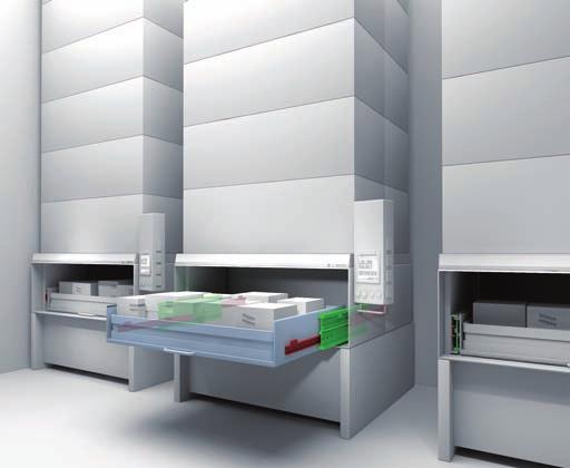
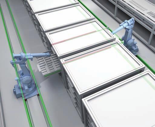
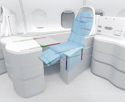
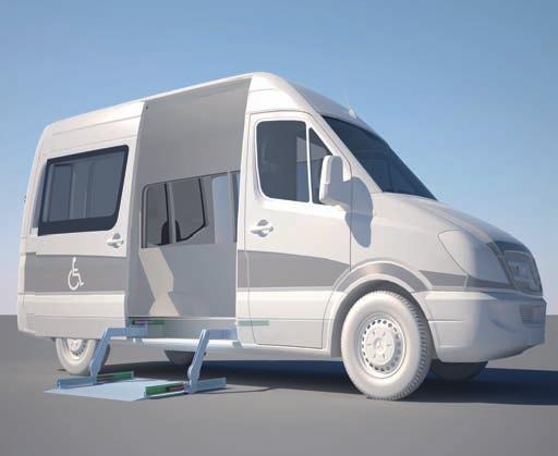
3 Core Competencies Full range of linear rails, telescopic rails and actuators Worldwide presence with branches and distributors Fast delivery all over the world Large technical know-how for applications Standard solutions Collaboration Customization Wide range of products and sizes Linear rails with roller and caged ball bearings Heavy duty telescopic rails elt or ball screw driven linear actuators Multi-axis systems International know-how in several industries Project consultancy Maximizing performance and cost optimization Special products Research and development of new solutions Technologies dedicated to different sectors Optimal surface treatment pplications erospace Railway Logistics Industrial Machines Medical Specialty Vehicles Robotics Packaging
4 Content Telescopic Rail Telescopic Rail Technical features overview 1 Product explanation Telescopic Rail: Seven models with full and partial extension 2 Technical data Performance characteristics and notes 3 Dimensions and load capacity SN DSS DS DSD DSE DSC DE DE...D DN DMS DRT 4 Technical instructions Telescopic rail selection. Static load check Deflection Static load Service life Speed, Extension and extraction force, Double-sided stroke, Temperature nticorrosive protection, Lubrication Fixing screws Installation instructions Ordering key Ordering key with explanations TR-2 TR-5 TR-6 TR-10 TR-13 TR-14 TR-16 TR-18 TR-20 TR-23 TR-25 TR-28 TR-30 TR-32 TR-33 TR-34 TR-35 TR-38 TR-39 TR-40 TR-41 TR-43


5 Opti Rail Opti Rail 1 Product explanation Fully extending telescopic rails for manual movement OR-2 2 Technical data Performance characteristics and notes OR-4 3 Dimensions and load capacity LTH30 RF LTH30 KF LTH45 RF LTH45 KF LTF44 OR-5 OR-6 OR-7 OR-8 OR-9 4 Technical instructions Load capacity, Extension and extraction force nticorrosive protection, Temperature, Lubrication, Installation instructions OR-10 OR-11 Ordering key Ordering key with explanations OR-12 Light Rail Light Rail 1 Product explanation Light telescopic rails, with full or partial extension LR-2 2 Technical data Performance characteristics and notes LR-4 3 Dimensions and load capacity LPS 38 LFS 46 LFS 57 LFS 58 SC LFS 70 LFX 27 DRX/DRS LR-5 LR-6 LR-7 LR-8 LR-9 LR-10 LR-11 4 Technical instructions Load capacities Speed, Temperature, Lubrication, Corrosion protection Installation instructions, DRX/DRS installation LR-12 LR-13 LR-14 Ordering key Ordering key with explanations LR-16 Guides suitable for all applications


6 Technical features overview Reference Section Family Product Type Profile Hardened raceways Self alignment Extension alls Slider Rollers nticorrosion SN Cold Drawn + 50% ** DE Cold Drawn % ** DS Cold Drawn % ** Telescopic Rail DSE DSC Cold Drawn Cold Drawn % 100% ** ** DN Cold Drawn % ** DMS Cold Drawn % ** DRT Cold Drawn + 100% ** Opti Rail LTH LTF Cold Drawn Cold Drawn % 100% ** ** LPS Formed Sheetmetal ++ 50% Light Rail LFS LFX Formed Sheetmetal Formed Sheetmetal % 100% DRX/DRS Formed Sheetmetal % The information shown must be verifi ed for the specifi c application. For a complete view of technical data, please consult our catalogs on * The maximum value is defi ned by the application. ** Different anti-corrosion treatments are available. For more information, please contact Rollon. *** For more information, please contact Rollon.
 Operating temperature 22-28-35-43-63 44247 30973 61688 1013 1970 0,8 +++ -30 C/+170 C T R 22-28-35-43-63 7198 3062 26338 2026 1970 0,8 +++ -30 C/+170 C")
7 Size Max. load capacity per slider C O rad C O ax Max. dynamic load capacity C 100 Max. stroke Max. rail length Max. extension speed [m/s] Rigidity (deflection) Operating temperature , C/+170 C T R , C/+170 C , C/+110 C , C/+110 C , C/+110 C , C/+170 C , C/+110 C , C/+110 C *** , C/+170 C O R , C/+170 C *** , C/+40 C L R *** , C/+40 C *** , C/+200 C *** , C/+100 C C Orad C Oax
8
9 Telescopic Rail

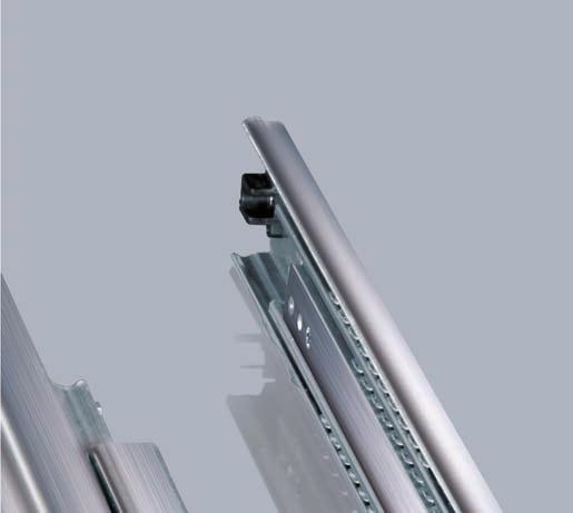
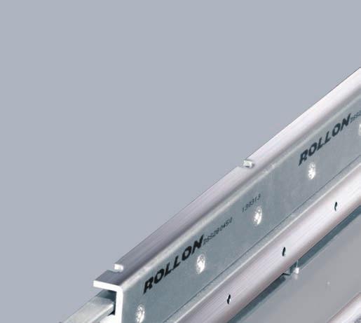
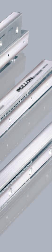
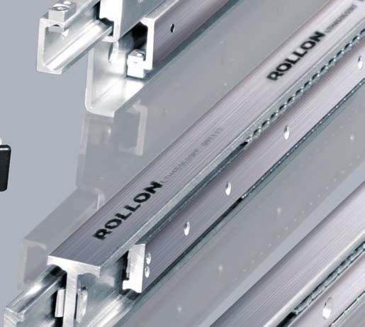
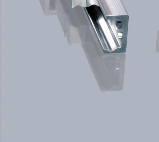
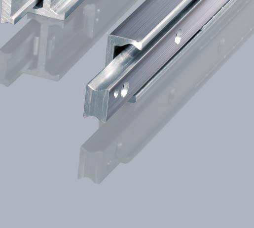
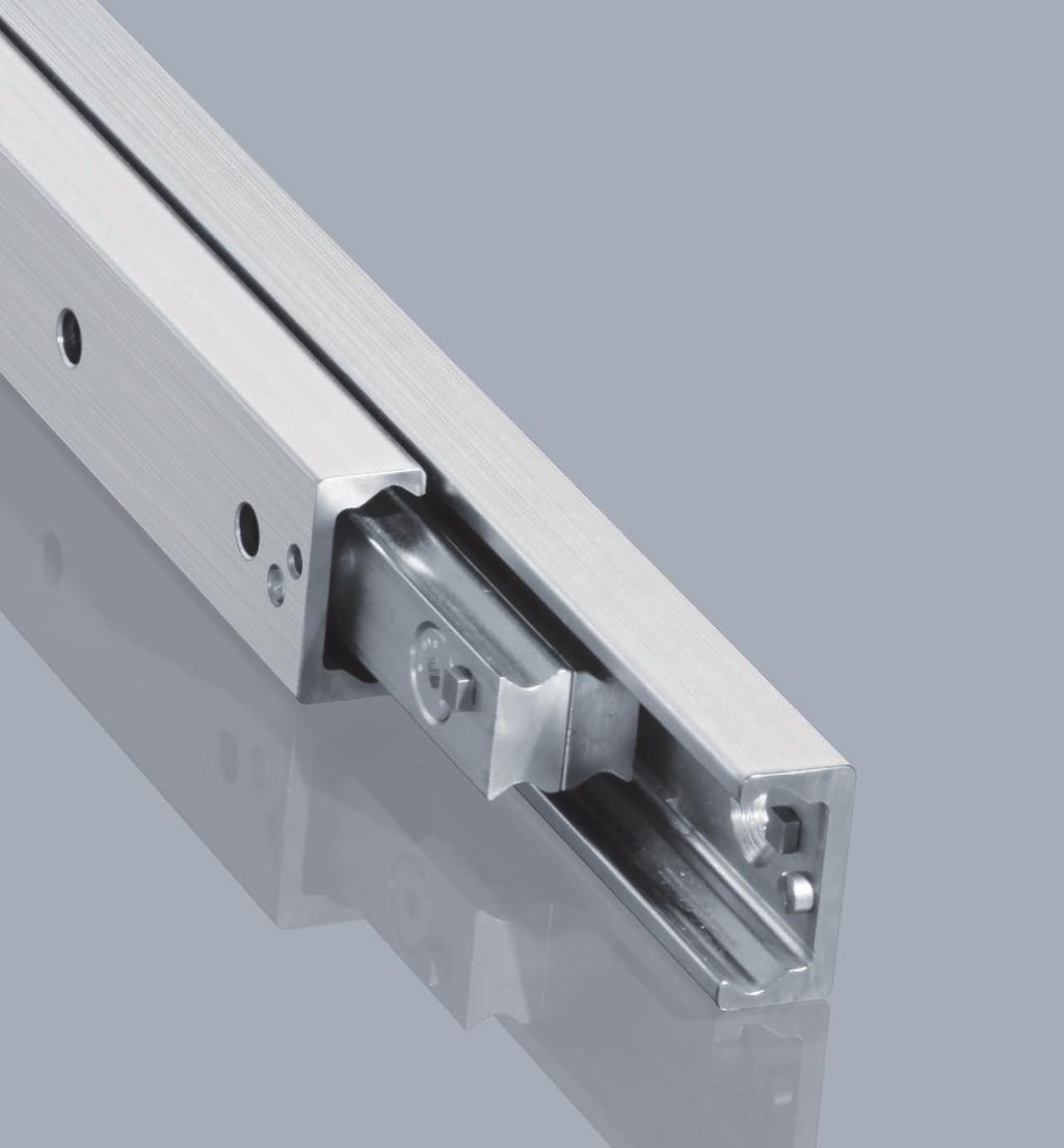
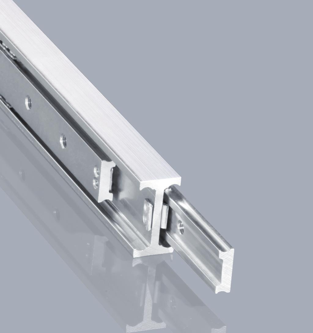
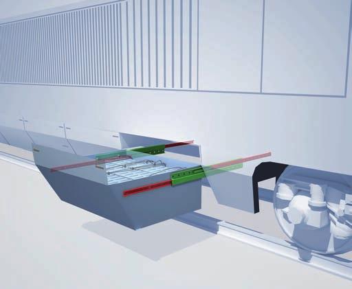
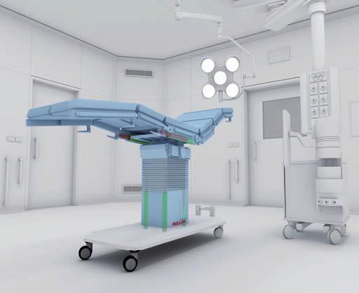
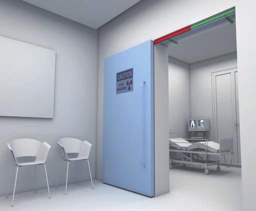
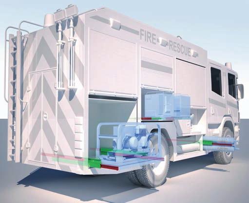
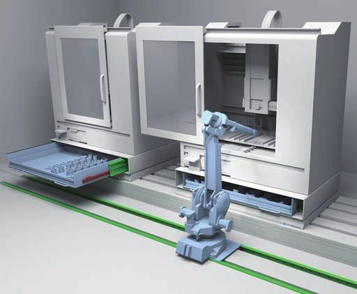
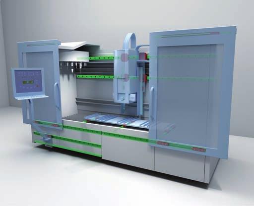
10 1 Product explanation Product explanation Telescopic Rail: Seven models with full and partial extension Fig. 1 The Telescopic Rail product line is made up of seven models with full and partial extension and various cross-sections and intermediate elements in S-shape, I-beam or square. High loads in combination with cost-effi ciency and free movement have long been the outstanding properties of the Telescopic Rail product line. The most important characteristics: High load capacity with low defl ection Rigid intermediate elements Standardized hole locations Zero-play running even with maximum load Space saving design High reliability Preferred areas of application of the Telescopic Rail product family: Railcars (e. g. maintenance and battery extensions, doors) Construction and machine technology (e.g., housings and doors) Logistics (e.g., extensions for containers or gripper movements) utomotive technology Packaging machines everage industry Special machines TR-2


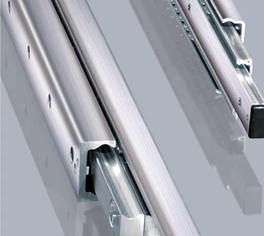
11 Telescopic Rail SN Partially extending telescopic rail consisting of a guide rail and a slider. This compact and simple design allows for very high load capacities. When the guide rail is mounted to a structure a very high rigidity system is created. Fig. 2 DS Fully extending telescopic rail consisting of a fi xed guide rail, an identical moving guide rail, and an S-shaped intermediate element. This has a high moment of inertia and high rigidity in a slim size. This results in a high loading capacity with low defl ection in the extended state. The DS series is available in three different designs: DSS version with single direction stroke. DS version with single direction stroke, and locking capability in the extended state, and the DSD version with double direction stroke. Fig. 3 DSE Telescopic rail with a 150% extension of it s length, made by four elements. It has a high rigidity, thanks to the intermediate elements with a high moment of inertia, in a streamlined shape. This results in a high load capacity, with reduced bending even when the telescopic guide is fully extended. Fig. 4 DSC Fully extending telescopic rail consisting of a compact and fl exurally rigid intermediate element that connects two different sized guide rails with each other as a fi xed and moving element. This design makes it possible to reduce all components to the necessary size and length for achieving the full stroke. The DSC series features high rigidity and a high load capacity in a compact size. This results in an optimal combination of performance and weight reduction. Fig. 5 TR-3


12 1 Product explanation DE Fully extending telescopic rail consisting of two guide rails, which are mounted on an I-beam profi le to form the intermediate element, one moveable slider and one fi xed slider which mounts onto the structure. The square cross-section allows a compact size with high load capacities and low defl ection, especially with radial loading. lso available with a double stroke design, which includes an eccentrically located driving disc for simultaneous movement. For double sided extensions, a dedicated DE...D version is available with a driving disc. Fig. 6 DN Fully extending telescopic rail consisting of two guide rails, one which is fi xed to a structure, and one which is moveable, and two sliders which are mounted together and form the intermediate element. The size is similar to the DE series and offers good protection from contamination of the ballcage. Fig. 7 DMS Heavy load telescopic consisting of elements from the SN series and an extremely rigid I-beam profi le as the intermediate element. This fully extending telescopic rail is used to accept very heavy loads with low defl ection. Fig. 8 DRT Fully extending telescopic rail on a roller slide base consisting of the S-shaped intermediate element from the DS series, and elements of the proven Compact Rail roller slider system. The use of roller sliders instead of a linear bearing as the load accepting element, enables a large resistance to contamination and an extremely quiet motion. Fig. 9 TR-4
13 Telescopic Rail Technical data Intermediate element Fixed element Movable element alls Internal ballcages Fig. 10 Performance characteristics: vailable sizes SN / DE: 22, 28, 35, 43, 63 vailable sizes DS: 28, 35, 43, 63 vailable sizes DSE: 28, 35, 43, 63 vailable sizes DSC: 43 vailable sizes DN: 22, 28, 35, 43 vailable size DMS: 63 vailable size DRT: 43 Induction hardened raceways Rails and sliders made of cold-drawn roller bearing carbon steel alls made of hardened roller bearing carbon steel Max. operating speed: 0.8 m/s ( 31.5 in/s ) ( depending on application ) SN, DE, DN, temperature range: -30 C to +170 C (-22 F to +338 F ), DS, DSE, DSC, DRT: -30 C to +110 C (-22 F to +230 F ) Electrolytic galvanised as per ISO 2081, increased anticorrosive protection on request (see pg. TR-39 nticorrosive protection) Remarks: Horizontal movement installation is recommended Vertical movement installation on request External end stops are recommended Double-sided stroke in SN, DSD, DE, DN series ( DMS on request ) Custom strokes on request ll load capacity data is based on one telescopic rail ll load capacity data is based on continuous operation Calculation of the service life is based exclusively on the loaded rows of balls For models DS, DMS and DRT, please observe right or left side use DRT 43 must be fi xed with Torx screws ( custom design, included in delivery ) SN 63 and DMS 63 can be fi xed with Torx screws as an alternative Fixing screws of property class 10.9 must be used for all telescopic rails Internal stops are used to stop the unloaded slider and the ball cage. Please use external stops as end stops for a loaded system TR-5

14 3 Dimensions and load capacity Dimensions and load capacity SN Set screw* M y M x Mz C 0ax H Length L H * Remove the set screw to reach all the fi xing holes. See also assembly instructions on page TR-41f. Fig. 11 Type Size Length L H Load capacities and moments* C 0ax M x [Nm] M y [Nm] M z [Nm] No. of holes , , , SN * The given load capacities and weights apply for a single extension , , , , Tab. 1 TR-6
15 Telescopic Rail Type Size Length L H Load capacities and moments* C 0ax M x [Nm] M y [Nm] M z [Nm] No. of holes SN , , , , , , , , , , , , , , , , , , , SN , , , , , , , , , Tab. 2 * The given load capacities and weights apply for a single extension TR-7
16 3 Dimensions and load capacity Type Size Length L H Load capacities and moments* C 0ax M x [Nm] M y [Nm] M z [Nm] No. of holes SN SN * The given load capacities and weights apply for a single extension Tab. 3 TR-8
17 Telescopic Rail SN SN SN 63 I I E 1 E 2 J F V 1 J F C 2 G G 1 Fixing holes (V) for countersunk head screws according to DIN Fixing holes (C) for socket cap screws according to DIN lternative fi xing with Torx screws in special design with low head (on request) Fig. 12 Type Size Cross-section Weight [kg/m] I J G E 1 E 2 [ ] V C F SN M4 - M M5 - M M6 - M M8 - M x 45 - M8 M Tab. 4 TR-9
18 3 Dimensions and load capacity DSS DSS with one-sided extension (single stroke) Length L H Fig. 13 Type Size Length L H Load capacity* ccessible holes / total Type Size Length L H Load capacity* ccessible holes / total / / / / / / / 10 DSS / / / / / / / / / 19 Tab. 5 * The given load capacities and weights apply for a single extension / / / / / / / / 13 DSS / / / / / / / / / 22 Tab. 6 * The given load capacities and weights apply for a single extension TR-10
19 Telescopic Rail Type Size Length L H Load capacity* ccessible holes / total Type Size Length L H Load capacity* ccessible holes / total / / / / / / / / / / / / / / / / 15 DSS / / 16 DSS / / / / / / / / / / / / / / / / 24 * The given load capacities and weights apply for a single extension / / 25 Tab / 25 Tab. 8 * The given load capacities and weights apply for a single extension TR-11
20 3 Dimensions and load capacity DSS DSS with one-sided extension (single stroke) Type Size Cross-section Weight [kg/m] K D J V V 1 J D DSS , ,5 M5 6, , , ,5 M6 10, M8 14, M10 32,60 Tab. 9 K 1 Fixing holes (V) for countersunk head screws according to DIN 7991 Fig. 14 TR-12
 for countersunk head screws according to DIN 7991 Fig. 16 The DS is built on the DSS design. The same load capacities, crosssections and available rail lengths apply (see pg.")
21 E L C Total length L (left rail) R (right rail) D Unlocking lever K V 1 J D V 1 J Telescopic Rail DS version with locking system for closed position Fig. 15 K 1 Fixing holes (V) for countersunk head screws according to DIN 7991 Fig. 16 The DS is built on the DSS design. The same load capacities, crosssections and available rail lengths apply (see pg. TR-10ff). Data in Table 10 are based on the special features of the locking mechanism. Please observe right or left installation for version DS. The maximum load on the locking in the extension direction is indicated by F max. Type Size L Total length C E F max Weight [kg/m] 28 from 290 to 1490* L DS 35 from 450 to 1730* L from 530 to 1970* L * for available lengths, see pg. TR-10, tab. 5 and 7 (DSS) Tab. 10 TR-13
22 3 Dimensions and load capacity DSD DSD with double direction stroke (double stroke) H Length L H Fig. 17 Type Size Length L H Load capacity* ccessible holes / total Type Size Length L H Load capacity* ccessible holes / total / / / / / / / 10 DSD / / / / / / / / / 19 Tab. 11 * The given load capacities and weights apply for a single extension / / / / / / / / 13 DSD / / / / / / / / 21 * The given load capacities and weights apply for a single extension / 22 Tab. 12 TR-14
23 Telescopic Rail Type Size Length L H Load capacity* ccessible holes / total Type Size Length L H Load capacity* ccessible holes / total / / / / / / / / / / / / / / / / / / 16 DSD 63 DSD / / / / / / / / / / / / / / / / / / / 25 * The given load capacities and weights apply for a single extension Tab. 14 * The given load capacities and weights apply for a single extension Tab. 13 DSD DSD with double direction stroke (double stroke) V 1 J Type Size Cross-section Weight [kg/m] K D J V DSD , ,5 M , , ,5 M M D M Tab. 15 K 1 Fixing holes (V) for countersunk head screws according to DIN 7991 Fig. 18 TR-15
24 3 Dimensions and load capacity DSE E version with extra stroke L H Length L Fig. 19 Type Size Length L H Load capacity* No. of holes fixed part No. of holes mobile part Type Size Length L H Load capacity* No. of holes fixed part No. of holes mobile part / / / / , / 8 8 DSE , / , / / / / / / Tab. 16 * The given load capacities and weights apply for a single extension / / / / / / DSE / / / / / / / / Tab. 17 * The given load capacities and weights apply for a single extension TR-16
25 Telescopic Rail Type Size Length L H Load capacity* No. of holes fixed part No. of holes mobile part Type Size Length L H Load capacity* No. of holes fixed part No. of holes mobile part / / / / / / / / / / / / / / / / / / DSE 63 DSE / / / / / / / / / / / / / / / / / / / * The given load capacities and weights apply for a single extension Tab. 19 * The given load capacities and weights apply for a single extension Tab. 18 DSE E version with extra stroke J V 1 Type Size Cross-section Weight [kg/m] K D J F V , ,5 M5 M5 8,4 D DSE 35 39, , ,5 M6 M6 13, M8 M8 19,9 F M8 M10 42,9 Tab. 20 K 1 Fixing holes (V) for countersunk head screws according to DIN 7991 Fig. 20 TR-17

26 3 Dimensions and load capacity DSC Length L H Lenght fixed element C 0ax Lenght movable element Fig. 21 Type Size Length L H Load capacities* Fixed element Movable element C 0ax ccessible holes / total Length ccessible holes / total Length / / / / / / / / / / / / / / / / / / DSC / / / / / / / / / / / / / / / / / / * The given load capacities and weights apply for a single extension / / Tab. 21 TR-18
27 Telescopic Rail DSC F V¹ J 1 Fixing holes (V) for countersunk head screws according to DIN 7991 bb. 22 Type Size Cross-section Weight [kg/m] J F V 1 DSC M8 M Tab. 22 TR-19
28 3 Dimensions and load capacity DE Set screw* C 0ax H Length L H * Remove the set screw to reach all the fi xing holes. See also assembly instructions on page TR-41f. Fig. 23 Type Size Length L H Load capacities* C 0ax No. of holes Type Size Length L H Load capacities* C 0ax No. of holes DEF DEV DEM DEF DEV DEM * The given load capacities and weights apply for a single extension Tab Tab. 24 * The given load capacities and weights apply for a single extension TR-20
29 Telescopic Rail Type Size Length L H Load capacities* C 0ax No. of holes Type Size Length L H Load capacities* C 0ax No. of holes DEF DEV DEM 35 Type Size Length L DEF Tab. 25 * The given load capacities and weights apply for a single extension H Load capacities* C 0ax No. of holes Tab. 27 * The given load capacities and weights apply for a single extension DEF DEV DEM Tab. 26 * The given load capacities and weights apply for a single extension TR-21
30 3 Dimensions and load capacity DE DE DEF 63 F F V 1 G G 1 Fixing holes (V) for countersunk head screws according to DIN 7991 Fig. 24 Type Size Cross-section Weight [kg/m] G F V DEF DEV DEM M4 M M5 M M6 M M8 M M Tab. 28 There are three options for mounting holes available for the DE series in sizes 22 to 43: Version DEF with threaded holes, Version DEV with counter-sunk holes, Version DEM, both variants (mixed) (see fi g. 24). Size 63 is only available with threaded holes. TR-22
31 Telescopic Rail DE...D DED with double direction stroke (double stroke) 65 N Pitch x 80 L (Rail length) 65 Slider length H D version (with a driving disc) Fig. 26 Fig. 25 The driving disc in the intermediate element in the DE...D versions acts to make sure that in bilateral strokes (double strokes) the intermediate element always returns to the correct position and does not remain in an undefi ned position. This design is available in sizes 28, 35, 43 and 63 with all three versions of the fi xing holes. This version is based on the standard DE series version, but differs in the technical characteristics for the construction methods. Please contact our technical service department for more information. Type Size Length L H Load capacities* Slider C 0ax No. of holes Type Size Length L H Load capacities* Slider C 0ax No. of holes DEF...D DEV...D DEM...D * The given load capacities and weights apply for a single extension Tab. 29 DEF...D DEV...D DEM...D Tab. 30 * The given load capacities and weights apply for a single extension TR-23
32 3 Dimensions and load capacity Type Size Length L H Load capacities* Slider C 0ax No. of holes Type Size Length L H Load capacities* Slider C 0ax No. of holes DED...D DEV...D DEN...D 43 DED version D Tab. 31 * The given load capacities and weights apply for a single extension DEF...D Tab. 32 * The given load capacities and weights apply for a single extension DED with double direction stroke (double stroke) Type Size Cross-section Weight [kg/m] F V M5 M5 4,04 DE...D M6 M6 6, M8 M8 10,50 F 1 Fixing holes (V) for countersunk head screws according to DIN 7991 V 1 Fig M8-20,60 Tab. 33 There are three options for mounting holes available for the DE...D series in sizes 28 to 43: Version DEF with threaded holes, Version DEV with counter-sunk holes, Version DEM, both variants (mixed). Size 63 is only available with threaded holes. TR-24

33 Telescopic Rail DN Set screw* C 0ax H Length L H * Remove the set screw to reach all the fi xing holes. See also assembly instructions on page TR-41f. Fig. 28 Type Size Length L H Load capacities* C 0ax No. of holes Type Size Length L H Load capacities* C 0ax No. of holes DN Tab. 34 * The given load capacities and weights apply for a single extension DN Tab. 35 * The given load capacities and weights apply for a single extension TR-25
34 3 Dimensions and load capacity Type Size Length L H Load capacities* C 0ax No. of holes Type Size Length L H Load capacities* C 0ax No. of holes DN Tab. 36 * The given load capacities and weights apply for a single extension DN Tab. 37 * The given load capacities and weights apply for a single extension TR-26
35 Telescopic Rail DN E V 1 1 Fixing holes (V) for countersunk head screws according to DIN 7991 Fig. 29 Type Size Cross-section Weight [kg/m] E V DN M M M M Tab. 38 TR-27

36 3 Dimensions and load capacity DMS Length L H Fig. 30 Type Size Length L H Load capacity* Fixed element ccessible holes / total Movable element ccessible holes / total / / / / / / / / / / / / / / 19 DMS / / / / / / / / / / / / / / / / / / 28 * The given load capacities and weights apply for a single extension Tab. 39 TR-28
37 Telescopic Rail DMS L (left rail) I R (right rail) I Fixed element Size 63 J K D C 2 J Fixed element Size 63 K V 1 D V 1 C 2 Movable element Size 43 1 Fixing holes (V) for countersunk head screws according to DIN Fixing holes (C) for socket cap screws according to DIN lternative fi xing with Torx screws in special design with low head (on request) Fig. 31 Type Size Cross-section Weight [kg/m] I K D J C V DMS M8 M8 43 Tab. 40 TR-29

38 3 Dimensions and load capacity DRT Length L H Fig. 32 Type Size Length L DRT 43 H * The given load capacities and weights apply for a single extension Load capacity* ccessible holes / total / / / / / / / / / / / / / / / / 25 Tab. 41 TR-30
39 K D C 3 J D J Telescopic Rail DRT L (left rail) R (right rail) C 3 K 3 Fixing holes for Torx screws in custom design with load head (included in scope of supply) Fig. 33 Type Size Cross-section Weight [kg/m] K D J C DRT M Tab. 42 TR-31

40 4 Technical instructions Technical instructions Telescopic rail selection Selecting the suitable telescopic rail should be done based on the load and the maximum permissible defl ection in the extended state. The load capacity of a telescopic rail depends on two factors: the loading capacity of the ballcage and the rigidity of the intermediate element. For mainly short strokes the load capacity is determined by the load-bearing capacity of the ballcage; for average and long strokes it is determined by the rigidity of the intermediate element. Therefore series, which otherwise contain comparable components, are also suited for differing load capacities. Static load check The values in the load capacity tables of the corresponding series (see Sect. 3, Product Dimensions, pg. TR-6ff) give the maximum permissible loading of a telescopic rail in the centre of the movable rail in the completely extended state. ll load capacity data is based on a telescopic rail. Typically, a pair of rails is used and the loading acts in the centre on both rails (see fi g. 35, P 1 ). In this case, the load capacity of a rail pair is: P 1 = 2 Fig. 34 Fig. 35 TR-32
41 Telescopic Rail Deflection If the load P acts vertically on the rail (see fi g. 38), the expected elastic defl ection of the individual telescopic rail in the extended state can be determined as follows: q f = P t (mm) Fig. 36 Whereby: f is the expected elastic defl ection in mm q is a stroke coeffi cient (see fi g. 39) t is a factor depending on the model of the telescopic rail (see fi g. 37) P is the actual load acting on the centre of a rail, in N lso refer to page TR-34 for checking the static load q Fig. 38 DS28 t = 180 DS35 t = 470 DS43 t = 800 DS63 t = 4000 DE22 t = 8 DE28 t = 17 DE35 t = 54 DE43 t = 120 DE63 t = 540 DN22 t = 3 DN28 t = 8 DN35 t = 13 DN43 t = 56 DMS63 t = 3500 DRT43 t = 800 DSC43 t = 800 in mm Fig. 37 Fig. 39 Note: The above formula (see fi g. 36) applies to a single rail. When using a rail pair, the load of the single rail is P = P 1 /2 (see pg. TR-32, fi g. 35). This estimated value assumes an absolutely rigid adjacent construction. If this rigidity is not present, the actual defl ection will deviate from the calculation. Important: With the partial extensions of the SN series, the defl ection is almost completely determined by the rigidity, i.e. by the moment of inertia of the adjacent construction. For guides Series DSE please contact the technical department of Rollon. TR-33
42 4 Technical instructions Static load The telescopic extension of the various series allow different forces and moments (see Sect. 3, Product dimensions, pg. TR-6ff). During the static tests the radial load capacity,, the axial load capacity, C 0ax, and moments M x, M y and M z indicate the maximum permissible values of the loads; higher loads negatively effect the running properties and the mechanical strength. safety factor, S 0, is used to check the static load, which takes into account the basic parameters of the application and is defi ned in more detail in the following table: Safety factor S 0 Neither shocks nor vibrations, smooth and low-frequency reverse, high assembly accuracy, no elastic deformations 1.5 Normal installation conditions Shocks and vibrations, high-frequency reverse, signifi cant elastic deformation Tab. 43 The ratio of the actual load to maximum permissible load may be as large as the reciprocal of the accepted safety factor, S 0, at the most. P 0rad 1 P 0ax 1 M 1 1 M 2 1 M 3 1 S 0 C 0ax S 0 M x S 0 M y S 0 M z S 0 Fig. 40 The above formulas are valid for a single load case. If two or more of the described forces act simultaneously, the following check must be made: P 0rad P 0ax M 1 M 2 M C 0ax M x M y M z 1 S 0 P 0rad = effective radial load = permissible radial load P 0ax = effective axial load C 0ax = permissible axial load M 1 = effective moment in the x-direction M x = permissible moment in the x-direction M 2 = effective moment in the y-direction M y = permissible moment in the y-direction M 3 = effective moment in the z-direction M z = permissible moment in the z-direction Fig. 41 TR-34
43 Telescopic Rail Service life The service life is defi ned as the time span between commissioning and the fi rst sign of fatigue or wear indications on the raceways. The service life of a telescopic rail is dependent on several factors, such as the effective load, the installation precision, occurring shocks and vibrations, the operating temperature, the ambient conditions and the lubrication. Calculation of the service life is based exclusively on the loaded rows of balls. In practice, the decommissioning of the bearing, due to its destruction or extreme wear of a component, represents the end of service life. This is taken into account by an application coeffi cient (f i in the formula below), so the service life consists of: δ 1 L km = 100 ( ) 3 W f i L km = calculated service life in km δ = load capacity factor in N W = equivalent load in N f i = application coeffi cient Fig. 42 pplication coefficient f i SN, DS, DE, DN, DRT, DSC Neither shocks nor vibrations, smooth and low-frequency direction change, clean environment Light vibrations and average direction change Shocks and vibrations, high-frequency direction change, very dirty environment Tab. 44 If the external load, P, is the same as the dynamic load capacity,, (which of course must never be exceeded), the service life at ideal operating conditions (f i = 1) amounts to 100 km. Naturally, for a single load P, the following applies: W = P. If several external loads occur simultaneously, the equivalent load is calculated as follows: P W = P rad + ( ax M + 1 M + 2 M + ) 3 C 0ax M x M y M z Fig. 43 TR-35
44 4 Technical instructions Load capacity factor δ Length SN Length DS... DSE DSC δ δ Tab Tab. 46 TR-36
45 Telescopic Rail Length DRT DMS Length DE... / DN DE δ δ Tab Tab. 48 TR-37
46 4 Technical instructions Speed The maximum operating speed is determined by the mass of the intermediate element, which moves with the movable rail. This reduces the maximum permissible operating speed with increasing length (see fi g. 44). Maximum acceleration: 1.2 m/s 2 Speed (m/s) Length (mm) Fig. 44 Opening and closing force The required actuation forces of a telescopic rail depend on the acting load and the defl ection in the extended state. The force required for opening is principally determined by the coeffi cient of friction of the linear bearing. With correct assembly and lubrication, this is During the extension, the force is reduced with the elastic defl ection of the loaded telescopic rail. higher force is required to close a telescopic extension, since, based on the elastic defl ection, even if it is minimal, the movable rail must move against an inclined plane. Double-sided stroke For all designs allowing double-sided stroke, it must be noted that the position of the intermediate element is defi ned only in the extended state. In the extended state, the intermediate element can protrude by half of its length on each side. Exception is the SN series, which comes out as a partial extension without an intermediate element and the custom design of series DE with driving disc. The double-sided stroke in the SN, DE and DN series is achieved by removing the set screw. For the DSD series, the double-sided stroke is implemented by design adaptation. Double-sided stroke for series DMS on request. The DS and DRT series are not available with double-sided stroke. Temperature Series SN, DE, DN can be used up to an ambient temperature of +170 C (+338 F). lithium lubricant for high operating temperatures is recommended for temperatures above +130 C (+266 F). The DS, DSC, and DRT series have a useable range of -30 C to +110 C (-22 F to +230 F) due to of the rubber stop. TR-38
47 Telescopic Rail nticorrosive protection ll of our Telescopic Rail series have a standard anticorrosive protection by electrolytic galvanisation according to ISO If a higher resistance to corrosion is required, the guides are available with Rollon loy or chemical nickel treatment. For both versions stainless steel balls are provided. Numerous application-specifi c surface treatments are available upon request, e.g., FD approved nickel plating for use in the food industry. For more information please contact the Rollon Engineering. Lubrication Recommended lubrication intervals are heavily dependent upon the ambient conditions, speed and temperature. Under normal conditions, lubrication is recommended after 100 km operational performance or after an operating period of six months. In critical application cases the interval should be shorter. Please clean the raceways carefully before lubricating. Raceways and spaces of the ball cage are lubricated with a lithium lubricant of average consistency (roller bearing lubricant). Different lubricants are available on request for special applications: FD-approved lubricant for use in the food industry specifi c lubricant for clean rooms specifi c lubricant for the marine technology sector specifi c lubricant for high and low temperatures For specifi c information, contact the Rollon Engineering. TR-39
48 4 Technical instructions Fixing screws The DRT 43 telescopic rail must be fi xed with a custom designed Torx S d L K D screws with low cap head. The screws are included in the scope of supply. ll other rails are fi xed with counter-sunk or cap head screws as per DIN 7991 or In size 63 of the SN and DMS series, Torx screws with low head cap screws are available on request (see fi g. 45). Fig. 45 Size Screw type d D L K S 63 M8 x 20 M8 x M8 x 16 M8 x T40 Tab. 49 Recommended Standard fixing screw tightening torques Property class Size Tightening torque [Nm] Tab. 50 Prepare a suffi cient bevel on the threaded fi xing holes, according to the following table: Size evel (mm) 22 0,5 x x x x x 45 Tab. 51 evel Fig. 46 TR-40

49 Telescopic Rail Installation instructions In general and for SN, DE, DN, DS, DMS, DRT Fixed element Left side system* Load Structure Movable element Extension direction Movable element Right side system* * For models DS, DMS and DRT, please observe right or left side use General Internal stops are used to stop the unloaded slider and the ball cage. Please use external stops as end stops for a loaded system. To achieve optimum running properties, high service life and rigidity, it is necessary to fi x the telescopic rails with all accessible holes on a rigid and level surface. In order to reach all mounting holes for the SN, DEV, DEM and DN series it is necessary to remove the locking screw in the rail during assembly and then to reinsert it afterwards. When using two telescopic rails, please observe the parallelism of the installation surfaces. The fi xed and movable rails fi t to the rigid assembly construction. Telescopic Rail guides are suitable for continuous use in automatic systems. For this, the stroke should remain constant in all moving cycles and the operating speed must be checked (see pg. TR-38, fi g. 44). The movement of the telescopic rails is enabled by internal ballcages, which could experience an offset from the original position with differing strokes. This phase offset can have a negative effect on the running properties or limit the stroke. If differing strokes occur in an application, the drive force must be suffi ciently dimensioned in order to appropriately synchronise the ballcage offset. Otherwise, an additional maximum stroke must be planned regularly to ensure the correct position of the ballcage. Fig. 47 SN Series SN accepts radial and axial loads and moments in all principle directions. Horizontal and vertical application is possible. Prior to vertical installation, we recommend contacting Rollon technical support. The installation of two partial extensions on a profi le provides a load capable full extension. For individual solutions, please contact Rollon technical support. DE / DN Series DE and DN accept radial and axial loads. Horizontal and vertical application is possible. Prior to vertical installation, we recommend you contact Rollon technical support. The functionality of custom design DE...D is only guaranteed if the stroke available is completely used. DS / DSE / DMS / DRT Series DS, DES, DMS and DRT accept radial loads. This should act in the vertical cross-sectional axis on the movable rails. Horizontal and vertical application is possible. Prior to vertical installation, we recommend you contact Rollon technical support. When installing make sure that the load is placed on the movable element (the lower rail) (see fi g. 47). The opposite assembly negatively affects the function. Installation must be done on a rigid structure using all accessible fi xing holes. Pay attention to the parallel alignment during assembly with paired application. TR-41

50 4 Technical instructions Installation instructions For DSC DSC system in retracted state Left side system Load Structure Fixed element Right side system Extension direction Fixed element DSC system in extended state Left side system Fixed element Structure Movable element Load Right side system Extension direction Movable element Fig. 48 DSC The DSC series absorbs radial and axial loads, in which case radial load directions are preferable. Horizontal and vertical use is possible. Prior to vertical installation we recommend inspection by the application engineers. During installation make sure that the load is mounted on the movable element (see Fig. 48). Reverse installation will impair proper functioning. The installation must be performed on a rigid structure, using all accessible mounting holes. Important: The length of the slider (fi xed element) is different from the system length. See Table 21 on page TR-18 for DSC load ratings. The table also provides information on the accessible mounting holes. Important: The slide (fi xed element) must be mounted in the front position when the system is retracted in order to achieve the entire stroke. If used in pairs, make sure the elements are aligned parallel during mounting. TR-42
51 Telescopic Rail Ordering key Telescopic rails DS L NIC Expanded surface protection is deviation from standard (ISO 2081) see pg. TR-37, nticorrosive protection Right (R) or left (L) version (only for series DS, DMS, DRT) see pg. TR-5 Remarks, if deviating from standard stroke (catalogue data) see pg. TR-6ff Product dimensions and Ordering key for special strokes Length see pg. TR-6ff Product dimensions Size see pg. TR-6ff Product dimensions Product type see pg. TR-6ff Product dimensions Ordering example 1: SN Ordering example 2: DS L-NIC Ordering example 3 (rail DE...D): DEF28D-0690 Notes on ordering: Information for right and left side installation and for expanded surface protection is only necessary if required. Rail lengths and stroke lengths are always stated with 4 digits. Please pad with zeroes to fi ll in for lengths with less than 4 digits, e.g. 515mm length is 0515 Special strokes Special strokes are defi ned as deviations from standard stroke H. They are each available as multiples of the values in tab. 52 and 53. These values are dependent on the spacing of the ballcage. Type Size modification Type Size modification SN Tab. 52 modifi cation of series DMS on request. No stroke modifi cation is possible for the DSD, DSC and DRT series. Each stroke modifi cation infl uences the load capacities stated in the catalogue. It is possible that after a stroke modifi cation important fastening holes might no longer be accessible. For more information please contact the Rollon Engineering. DSS DE DN DSE , Tab. 53 TR-43
52 Notes Notes TR-44
53 Telescopic Rail Notes TR-45
54
55 Opti Rail


56 1 Product explanation Product explanation Fully extending telescopic rails for manual movement Fig. 1 Range of fully extending telescopic rails, extremely compact and highly rigid, with reduced defl ection even when the telescopic rail is fully extended. The steel ball bearings ensure a high load capacity. The most important characteristics: Full extension Compact construction Quiet and smooth operation Long life Reliable operation 2 types of hole pitch Preferred areas of application: Railway (e. g. maintenance and battery extensions) Special Vehicles (e.g. fi reworks, ambulance, mobile shops) Professional furniture Special machines Industrial drawers OR-2
57 Opti Rail LTH Fully extending telescopic rail made of cold drawn steel, consisting of two rails, one fi xed and one moveable, and of a central I-beam profi le element. This element has high inertia and a very rigid construction, while boasting a very compact design. This ensures a high load capacity and reduced defl ection even when the telescopic rail is fully extended. Fig. 2 LTF Fully extending telescopic rail consisting of two guide rails as fi xed and movable elements and an S-shaped intermediate element. This special shape allows an extremely slim and compact design for movements that are only occasionally executed. Fig. 3 O R OR-3
 vailable sizes LTH: 30 and 45 vailable sizes LTF: 44 Sliders and LTH central element made of steel Cf53 Sliders and LTF central element made of steel C43 Note:")
58 2 Technical data Technical data Exterior rail Interior rail Intermediate element Fig. 4 Performance characteristics Temperature range: -30 C to +170 C (-22 F to +338 F) Max. operating speed: 0.3 m/s (depending on application) vailable sizes LTH: 30 and 45 vailable sizes LTF: 44 Sliders and LTH central element made of steel Cf53 Sliders and LTF central element made of steel C43 Note: Horizontal movement installation is recommended Vertical movement installation on request Custom strokes on request ll load capacity data are based on one telescopic rail Fixing screws of property class 10.9 must be used for all telescopic rails Internal stops are used to stop the unloaded slider and the ball cage. Please use external stops as end stops for a loaded system. OR-4
59 Opti Rail Dimensions and load capacity LTH30 RF m n n n Length F Fig. 5 Type Size Length m n F Load capacity* No. of holes Weight* [kg] LTH M * The given load capacities and weights apply for a single extension Tab. 1 O R OR-5
60 3 Dimensions and load capacity LTH30 KF = 50 = 50 m n Length F Fig. 6 Type Size Length m n F Load capacity* No. of holes Weight* [kg] , LTH M * The given load capacities and weights apply for a single extension Tab. 2 OR-6
61 Opti Rail LTH45 RF m n n n Length F Fig. 7 Type Size Length m n F Load capacity* No. of holes Weight* [kg] LTH M * The given load capacities and weights apply for a single extension Tab. 3 O R OR-7
62 3 Dimensions and load capacity LTH45 KF = 50 = 50 m n Length F Fig. 8 Type Size Length m n F Load capacity* No. of holes Weight* [kg] LTH M Tab. 4 * The given load capacities and weights apply for a single extension OR-8
63 Opti Rail LTF44 11,5 F D 11,5 1,5 G m n n m Length L H Fig. 9 Type Size Length L H Load capacity Cross-section Fixed and movable rail Weight [kg/m] D G F m n No. of holes , , O R , , ,5 LTF ,5 M , Tab. 5 OR-9
64 4 Technical instructions Technical instructions Load capacity The given load capacities are guidelines for one extension slide mounted vertically with uniform load distribution (area load) when using all mounting holes. The load values must be reduced in unfavorable conditions. Fig. 10 Opening and closing force The required actuation forces of a telescopic rail depend on the acting load and the defl ection in the extended state. The force required for opening is principally determined by the coeffi cient of friction of the linear bearing. With correct assembly and lubrication, this is During the extension, the force is reduced with the elastic defl ection of the loaded telescopic rail. higher force is required to close a telescopic extension, since, based on the elastic defl ection, even if it is minimal, the movable rail must move against an inclined plane. OR-10
65 Opti Rail nticorrosive protection ll of the OPTI RIL series have a standard anticorrosive protection by electrolytic galvanisation according to ISO If a higher resistance to corrosion is required, the guides are available with Rollon loy or chemical nickel treatment. For both versions stainless steel balls are provided. Numerous application-specifi c surface treatments are available upon request, e.g., FD approved nickel plating for use in the food industry. For more information please contact the Rollon Engineering. Temperature The OPTI RIL series can be used up to an ambient temperature of +170 C (+338 F). lithium lubricant for high operating temperatures is recommended for temperatures above +130 C (+266 F). Lubrication Recommended lubrication intervals are heavily dependent upon the ambient conditions, speed and temperature. Under normal conditions, lubrication is recommended after 100 km operational performance or after an operating period of six months. In critical application cases the interval should be shorter. Please clean the raceways carefully before relubrication. Raceways and spaces of the ball cage are lubricated with a lithium lubricant of average consistency (roller bearing lubricant). Different lubricants are available on request for special applications: FD-approved lubricant for use in the food industry specifi c lubricant for clean rooms specifi c lubricant for the marine technology sector specifi c lubricant for high and low temperatures For specifi c information, contact the Rollon Engineering. Installation instructions The internal stops are not designed to stop a moving load. They are only supposed to retain the ball-cage and prevent the internal parts from sliding out of the assembly. n external end-stop must always be installed to stop the moving load. To achieve optimum running properties, high service life and rigidity, it is necessary to fi x the OPTI RIL rails with all accessible holes on a rigid and level surface. Double-sided stroke available on request. When using an extension pair, please observe the parallelism of the installation surfaces. The fi xed rail and the movable one will assume the rigidity of the mounting structure. The movement of the extensions is enabled by internal ball cages, which could experience an offset from the original position with differing strokes. This phase offset can have a negative effect on the running properties or limit the stroke. If differing strokes occur in an application, the drive force must be suffi ciently dimensioned in order to appropriately synchronize the ball cage offset. s an alternative, an extra full stroke cycle can be performed after a number of cycles, in order to re-phase the ball cage in its correct position. O R OR-11
66 Ordering key Ordering key OPTI RIL LTH LTH KF NIC Hole pattern Expanded surface protection is deviation from standard (ISO 2081) see pg. OR-11 nticorrosive protection see pg. OR-5ff, if deviating from standard stroke (catalogue data) see pg. OR-5ff Product dimensions and Ordering key for special strokes Length see pg. OR-5ff Product dimensions Size see pg. OR-5ff Product dimensions Product type see pg. OR-5ff Product dimensions Ordering example 1: LTH KF Ordering example 2: LTH KF-NIC Notes on ordering: Rail lengths and strokes are always stated with 4 digits. Please use zeroes to fi ll in for lengths with less than 4 digits LTH Special strokes Special strokes are defi ned as deviations from standard stroke. They are each available as multiples of the values in tab. 6. These values are dependent on the spacing of the ballcage. Type Size modification LTH 30 15, Tab. 6 Each stroke modifi cation infl uences the load capacities stated in the catalogue. For more information please contact Rollon pplication Engineering. LTF LTF NIC Length Expanded surface protection is deviation from standard (ISO 2081) see pg. OR-11 nticorrosive protection see pg. OR-9ff Size see pg. OR-9ff Product type see pg. OR-9ff OR-12
67 Opti Rail Notes O R OR-13
68

69 Light Rail

70 1 Product explanation Product explanation Light telescopic rails, with full or partial extension Fig. 1 The Light Rail product family consists of fi ve series with full and partial extensions in a lightweight design. It is ideal for applications in which the mass of the rail is just as important as the bending rigidity. The most important characteristics: Light and quiet running with heavy loads Long service life without maintenance Effective self-cleaning of the ball track High functional reliability Structural elasticity capable of absorbing minor impacts and absence of permanent deformation Not sensitive to side impacts Preferred areas of application: everage industry utomotive Construction and machine technology (e.g., housing) Packaging machines Railcars (e. g., maintenance and battery extensions) Special machines LR-2

71 Light Rail LPS 38 Partial extension with rails made of hot-dipped galvanized steel and plastic ball cages. LFS 46 Detachable internal rail which can be released with a latch. Rails are made of bright chrome-plated steel, the ball cages of steel and plastic. Roll back protection in closed position. Fig. 2 LFS 57 Full extension with rails made of hot-dipped galvanized steel and zincplated steel ball cages. Roll back protection in closed position. Fig. 3 LFS 58 SC Full extension with automatic retraction and damping. The automatic retraction system is assisted by a spring-loaded mechanism that allows the rail to get back to a complete retraction before reaching the closed position. Fig. 4 LFS 70 Full extension with rails made of zinc-plated galvanized and blue passivated steel. The ball cages are made of zinc-plated steel. Heavy load end stop in opened and closed position. Roll back protection in closed position. Fig. 5 LFX 27 The stainless steel full extension consists of two inner guide rails that, connected to a double-t profi le, form the intermediate element and two outer rails that form the connection to the connecting construction as fi xed and moving element. The square cross-section allows a compact design of high load ratings and low defl ection. DRX-DRS Roller type telescopic rail made of stainless or galvanized steel. Corrosion resistant even if scratched, exposed to solvents or to shocks. Fig. 6 Fig. 7 Fig. 8 LR-3
72 2 Technical data Technical data Intermediate element Exterior rail all cage Interior rail Fig. 9 Performance characteristics: Extension speed (depending on application): Extension distance mm: max. 0.5 m/s ( in/s ) Extension distance 600 mm: max. 0.4 m/s ( in/s ) Extension distance 700 mm: max. 0.3 m/s ( in/s ) LFS 58 SC series with automatic retraction Temperature range: from +10 C to +40 C, for DRX/DRS From -30 to C Temporary storage and transport temperature: -20 C to max. +80 C (-4 F to +176 F) ll systems are lubricated for life LFS/LPS rail material: hot galvanized or chromed steel LFS/LPS ball bearing cage material: galvanized steel or plastic LFS/LPS ball bearing material: hardened carbon steel DRX rail material: stainless steel ISI 316L DRS rail material: galvanized steel ISO 2081 compliant Remarks: ssembly in cross-sectional width, here a positive tolerance of +0.5 mm is recommended (mounted under tension). If the extensions are installed with too small a tolerance, the service life is decreased Load capacity is per single rail (not per pair) Cycle data applies to the use of an extension pair (recommended) Vertical use of extensions (radial load) is recommended If mounted in a horizontal position, the load capacity will be reduced (see p. LR-12 ) Cathodic edge protection, additional corrosion protection with powder coating on request Roll back protection in closed position is friction locked (except LPS 38) Not suitable for moments must be used as extension pair LR-4
73 Light Rail Dimensions and load capacity LPS 38 Length 13.0 Length V ,1 X 37.5 M4 (2x) ,7 Installation space Fixing with M5 screws DIN966 / UNI 7689 ll dimensions given in mm Fig. 10 Type Size Length Extension loss * X Load capacity** Load capacity** Weight** V C 0ax [kg] LPS 38 * The stroke is the difference of the length and the extension loss V ** The given load capacities and weights apply for a single extension Tab. 1 Note: The given load capacities are guidelines with 100,000 cycles and uniform load distribution (area load) when using all mounting holes. The load values must be reduced in unfavorable conditions. LR-5
74 3 Dimensions and load capacity LFS Length -2 mm C Length 35 D E 9 12,6 12,7 9 12,7 4,4 4,4 x 9,3 Latch for separable interior rail 6,3 6,3 4,6 x 9,5 4,6 4,6 4,6 x 9, Installation space Fixing with screws M4 DIN966 / UNI 7689 ll dimensions given in mm Fig. 11 Type Size Length C D E Load capacity* Load capacity* Weight* C 0ax [kg] LFS Tab. 2 * The given load capacities and weights apply for a single extension Note: The given load capacities are guidelines with 50,000 cycles and uniform load distribution (area load) when using all mounting holes. The load values must be reduced in unfavorable conditions. LR-6
75 Light Rail LFS Length 50 8/90 9,5/90 5,1 Length , C Installation space Fixing to the internal rail with countersunk head screws M4 DIN966 / UNI 7689 Fixing to the external rail with countersunk head screws M5 DIN966 / UNI 7689 ll dimensions given in mm Fig. 12 Type Size Length * C Load capacity** Load capacity** Weight** C 0ax [kg] LFS 57 * The stroke is the sum of the length and the over extension ** The given load capacities and weights apply for a single extension Tab. 3 Note: The given load capacities are guidelines with 100,000 cycles and uniform load distribution (area load) when using all mounting holes. The load values must be reduced in unfavorable conditions. LR-7
76 3 Dimensions and load capacity LFS 58 SC /90 9,5/90 5,1 Length , C Installation space Fixing to the internal rail with countersunk head screws M4 DIN966 / UNI 7689 Fixing to the external rail with countersunk head screws M5 DIN966 / UNI 7689 ll dimensions given in mm Fig. 13 Type Size Length C Load capacity* Weight* [kg] LFS 58 * The given load capacities and weights apply for a single extension Tab. 4 Note: The given load capacities are guidelines with 100,000 cycles and uniform load distribution (area load) when using all mounting holes. The load values must be reduced in unfavorable conditions. Horizontal installation is not possible due to the damping system. The damping effect is reduced for loads of 450 N and higher per extension pair. LR-8
77 Light Rail LFS Length -3 mm D C x 16 ø 6.5 x 9.5 / x 16 ø 6.5 x 9.5 / 90 C D Length Installation space Fixing with countersunk head screws M5 DIN 966 / UNI 7689 ll dimensions given in mm Fig. 14 Type Size Length C D Load capacity* Load capacity* Weight* C 0ax [kg] LFS 70 * The given load capacities and weights apply for a single extension ** cycles ** ** 1, ** 150 2, ** 2,32 1,55 975** 1, ** 2, ** 3, ** 100 4,25 Tab. 5 Note: The given load capacities are guidelines with cycles and uniform load distribution (area load) when using all mounting holes. The load values must be reduced in unfavorable conditions. LR-9
78 3 Dimensions and load capacity LFX 27 Hub Length Länge 27,2 25 Length Länge ,0 +0,5 Installation Einbauraum space ø 4,1 ø 4,1 Fig. 15 Type Size Length Load capacity* Weight* C 0ax C 0ax to cycles to cycles [kg] , ,49 LFX , , , ,82 * The given load capacities and weights apply for a single extension Tab. 6 LR-10
79 Light Rail DRX/DRS F L I G 24,3 m n n n n m H 65,5 36 N f * * Number of mounting holes Fig. 16 Type Size Length L H Load capacity* m n N f [2 rails] Fixed and movable rail Holes for screws Weight [kg/m] F G I DRX DRS * The given load capacities and weights apply for a single extension M ,4 6,4 2 Tab. 7 LR-11

 For horizontal mounted extensions the load capacity is reduced (see pg. LR-5ff).")
80 4 Technical instructions Technical instructions Load capacities Vertical installation (radial load) The given loading capacities are guidelines for an extension rail vertically mounted with uniform load distribution using all mounting holes. The load values must be reduced in unfavorable conditions. Fig. 17 Horizontal installation (axial load) For horizontal mounted extensions the load capacity is reduced (see pg. LR-5ff). The DRS/DRX series is not suitable for use on horizontal mounting (axial loads) Fig. 18 LR-12
81 Light Rail Speed The extension speed is determined by the size of the intermediate elements. Therefore, the maximum extension speed is inversely proportional to the overall extension of the rails (see fi g. 19). The maximum extension speed is also directly related to the applied load and operating time. The indicated data refers to continuous operation at the maximum load capacity. m/s 0,6 0,5 0,4 0,3 0,2 0,1 Speed Speed mm Fig. 19 Temperature Continual operating temperature of the Light Rail extensions is +10 C to +40 C. Temporary storage and transport temperature: -20 C to max. +80 C. The operating temperature for the DRX/DRS rails ranges from - 30 C to C. For more information please contact the Rollon pplication engineering department. Lubrication ll extensions of the Light Rail product family are lubricated for life. Different lubricants for special applications are available upon request. Example: Lubricant with FD approval for use in the food industry. For more information please contact the Rollon pplication engineering department. Corrosion protection ase material for the Light Rail product family is cold-rolled, hot-dipped galvanized steel. The cathodic edge protection offers a perfect combination of quality and cost-effi ciency. The surface protection conforms to RoHS. The DRX/DRS series rails are also available in the stainless steel version for a high corrosion resistance. For more information please contact the Rollon pplication engineering department. LR-13


82 4 Technical instructions Installation instructions The existing internal stops are not designed to stop the moving load. They are only supposed to retain the ball-cage and prevent the internal parts to slide out of the assembly. n external end-stop must always be installed to stop the moving load. To achieve optimum running properties, high service life and rigidity, it is necessary to fi x the Light Rail extensions with all accessible holes on a rigid and level surface. When using an extension pair, please observe the parallelism of the installation surfaces. The fi xed and movable rails will assume the rigidity of the mounting structure. Horizontally installed guides Horizontally intalled extesions can support tension or compression loads (see fi gs. 20 and 21). For the horizontal mounting of extensions with compression loads, please take the following conditions into account: The Hertzian stress of the balls in no longer effective due to the expansion of the rail profi le; the nominal tension tolerance of +0.5 mm is eliminated due to the installation confi - Light Rail full and partial extensions are suitable for use in automatic systems. For this, the stroke should remain constant in all moving cycles and the extension speed must be checked (see pg. LR-13, fi g.19). The movement of the extensions is enabled by internal ball cages, which could experience an offset from the original position with differing strokes. This phase offset can have a negative effect on the running properties or limit the stroke. If differing strokes occur in an application, the drive force must be suffi ciently dimensioned in order to appropriately synchronize the ball cage offset. s an alternative, an extra full stroke cycle can be performed every certain number of cycles, in order to re-phase the ball cage in its correct position. guration. oth the above mentioned conditions contribute to a signifi cant reduction of the axial load capacity. Horizontally-mounted rails (axial load) also determine a considerably higher defl ection of the extended tips if compared to traditionally verticallymounted rails (radial load). DRX/DRS installation Fig. 20 Fig. 21 During installation care must be taken that the movable elements are To achieve optimum running properties, high service life and rigidity, assembled as in the fi gure; i.e. as the lower rail. The opposite upsidedown assembly negatively affects the function. rigid and level surface. it is necessary to fi x the telescopic rails with all accessible holes on a Internal stops are used to stop the unloaded slider and the ball cage. When using two telescopic rails, please observe the parallelism of the Please use external stops as end stops for a loaded system. installation surfaces. The fi xed and movable rails fi t to the rigid assembly construction. Fixed element Left side system Load djacent construction Movable element Extension direction Movable element Right side system Fig. 22 LR-14
83 Light Rail Ordering key Light Rail LFS SC Rail type utomatic retraction only in LFS 58 SC Rail length in mm see pg. LR-5 Size see pg. LR-5 see pg. LR-5 see pg. LR-8 Ordering example: LFS SC Notes on ordering: The rail lengths are always indicated as 4 digits with 0 prefi xes LR-15

84 Guides suitable for all applications Railway Medical Logistics

85 erospace Special Vehicles Industrial
86
87
 211 95 747 0 www.rollon.de - info@rollon.de ROLLON.V.")
88 ROLLON S.p.. - ITLY Via Trieste 26 I Vimercate (M) Phone: (+39) infocom@rollon.it Rollon ranches & Rep. Offi ces Distributors ranches: ROLLON GmbH - GERMNY onner Strasse D Düsseldorf Phone: (+49) info@rollon.de ROLLON.V. - NETHERLNDS Ringbaan Zuid D Zevenaar Phone: (+31) info@rollon.nl Rep. Offices: ROLLON S.p.. - RUSSI , Moscow, Varshavskoye shosse 17, building 1, offi ce 207. Phone: +7 (495) info.russia@rollon.com rollon.com ROLLON S..R.L. - FRNCE Les Jardins d Eole, 2 allée des Séquoias F Limonest Phone: (+33) (0) infocom@rollon.fr ROLLON Ltd - CHIN 51/F Raffl es City, 268 Xi Zang Middle Road, Shanghai (China) Phone: (+86) info@rollon.cn.com ROLLON Corporation - US 101 ilby Road. Suite Hackettstown, NJ Phone: (+1) info@rolloncorp.com ROLLON India Pvt. Ltd. - INDI 1st fl oor, Regus Gem usiness Centre, 26/1 Hosur Road, ommanahalli, angalore Phone: (+91) info@rollonindia.in Regional Manager: ROLLON - SOUTH MERIC R. Joaquim Floriano, 397, 2o. andar Itaim ibi , São Paulo, RSIL Phone: +55 (11) info@rollonbrasil.com Consult the other ranges of products Distributor ctuator Line ll addresses of our global sales partners can also be found at Changes and errors excepted. The text and images may be used only with our permission. TL_GC_EN_03/15
TELESCOPIC RAIL HEAVY
 TELESCOPIC RAIL HEAVY Every care has been taken to ensure the accuracy of the information contained in this catalogue, but no liability can be accepted for any errors or omissions. We reserve the right
TELESCOPIC RAIL.
 TEESCOPIC RAI www.rollon.com About Rollon Development of global business Continual expansion and optimization of the portfolio 1975 Parent company, Rollon S.r.l., founded in Italy 1991 Founding of Rollon
TELESCOPIC RAIL.
 TEESCOPIC RAI www.rollon.com About Rollon Development of global business Continual expansion and optimization of the portfolio 1975 Parent company, Rollon S.r.l., founded in Italy 1991 Founding of Rollon
...components in motion. Easy Rail
 ...components in motion Easy Rail Easy Rail Introduction The Easy Rail family have a compact cross-section and low-friction movement. Robust and Long Service Life Easy Rail s range of cross-sectional rail
Easy Slide Rails ov -easy_slide_divider - U pdated
 Easy Slide Rails ov-easy_slide_divider - Updated - 18-09-2017 163 Easy Slide Rails Easy Slide Rails Introduction The Easy Slide family of linear rails have a compact cross-section and low-friction movement.
Any reproduction, even partial, is allowed only by written permission by Rollco.
 EASYSLIDE Every care has been taken to ensure the accuracy of the information contained in this catalogue, but no liability can be accepted for any errors or omissions. We reserve the right to make changes
EASY RAIL.
 EASY RAIL www.rollon.com About Rollon Development of global business Continual expansion and optimization of the portfolio 1975 Parent company, Rollon S.r.l., founded in Italy 1991 Founding of Rollon GmbH
TELESCOPIC-LINE. Semi-telescopic-rail LST. Telescopic-rail LSE. Linear guides with ball-cage LSS
 TELESCOPIC-LINE Semi-telescopic-rail LST Telescopic-rail LSE Linear guides with ball-cage LSS 1 Ball rails LSS, LST and LSE The ball rails produced by Nadella are very compact and flexible products. Made
INDEX EASY RAIL: THE SOLUTION IS EASY...D4 EXAMPLES OF LOAD CAPACITIES...D5 ORDER CODES...D6 MOUNTING EXAMPLES...D7 TECHNICAL DATA...
 INDEX EASY RAIL: THE SOLUTION IS EASY...D4 EXAMPLES OF LOAD CAPACITIES...D5 ORDER CODES...D6 MOUNTING EXAMPLES...D7 TECHNICAL DATA...D8 STANDARD CONFIGURATIONS...D10 VERIFICATION UNDER STATIC LOAD...D12
TELESCOPIC RAILS HARDENED TELESCOPIC RAILS FOR HIGHLY DYNAMIC APPLICATIONS 7.1 PRODUCT OVERVIEW 7.2 PART EXTENSIONS 7.
 7 TELESCOPIC RAILS HARDENED TELESCOPIC RAILS FOR HIGHLY DYNAMIC APPLICATIONS PAGE 106 PAGE 116 PAGE 120 PAGE 126 7.1 PRODUCT OVERVIEW 7.2 PART EXTENSIONS 7.3 FULL EXTENSIONS 7.4 LINEAR GUIDES 105 PRODUCT
Easyslide FrontespizioEasyslide.indd 1 21/05/ :26:17
 Easyslide When you move. We move Rollon S.p.A. was founded in 1975 as a manufacturer of linear motion components. Today Rollon group is a leading name in the design, production, and sale of linear rails,
 UNILINE www.motiontech.com.au bout Rollon Development of global business Continual expansion and optimization of the portfolio 1975 Parent company, Rollon S.r.l., founded in Italy 1991 Founding of Rollon
Linear Line.
 Linear Line www.rollon.com When you move, we move. RollonSrl was set up in 1975 as a manufacturer of linear motion components. Today Rollon group is a leading name in the design, production and sale of
X-Rail FrontespizioXRai.indd 1 07/10/ :30:14
 X-Rail 1 Product explanation Product explanation X-Rail: orrosion resistant or zinc-plated steel linear bearings ig. 1 X-Rail is the product family of roller embossed guide rails for applications in which
...components in motion. Miniature Linear Guideways
 ...components in motion Miniature Linear Introduction Miniature linear guideway systems are widely used throughout industry for precise, compact applications. Precise and Stainless The gothic arch shape
Linear Guideways ov -linear -guidew ays-divider - U pdated
 Linear Guideways ov-linear-guideways-divider - Updated - 11-01-2017 163 Linear Guideways Linear Guideways Introduction L1016 Linear guideways Linear guideways are widely used throughout industry for heavy-duty
CURVILINE.
 CURVILINE www.rollon.com About Rollon Development of global business Continual expansion and optimization of the portfolio 1975 Parent company, Rollon S.r.l., founded in Italy 1991 Founding of Rollon GmbH
Technical features overview
 Technical features overview Reference Product name Extraction Size Material Stroke direction Snap Locking* 5 Damping Max. load capacity per pair [N] Product category Product Section Steel X* 4 A B BM EG
 A LEADING MANUFACTURER IN LINEAR MOTION GERALD SUMMERS is now an authorised distributor of Rollon TEL: 0800 055 6663 E-MAIL: SALES@GERALD-SUMMERS.CO.UK WWW.GERALD-SUMMERS.CO.UK CURVILINE www.rollon.com
Slotted nut NMG. Housing nut GWR. Bosch Rexroth AG. for economical constructions. a min. 0,3. M A = tightening torque of slotted nut.
 R310EN 3301 (2009.08) Precision Ball Screw Assemblies Bosch Rexroth AG 113 Slotted nut NMG for economical constructions B D d d1 b M A = tightening torque of slotted nut a min. 0,3 Polyamide insert Designation
Uniline System FrontespizioUnilineSystem.indd 1 22/11/ :32:41
 Uniline ystem 1 Uniline series Uniline series Uniline series description ig. 1 Uniline is a family of ready-to-install linear actuators. They consist of internal ompact Rail roller sliders and steel-reinforced
Mono Rail.
 Mono Rail www.rollon.com When you move. We move Rollon S.p.A. was founded in 1975 as a manufacturer of linear motion components. Today Rollon group is a leading name in the design, production, and sale
Inner block. Grease nipple. Fig.1 Structure of LM Guide Actuator Model KR
 LM Guide ctuator Model LM Guide + all Screw = Integral-structure ctuator Stopper Housing all screw Inner block Grease nipple Outer rail earing (supported side) Housing Stopper Double-row ball circuit earing
Curviline FrontespizioCurviline.indd 1 07/10/ :24:20
 Curviline When you move. We move Rollon S.p.A. was founded in 1975 as a manufacturer of linear motion components. Today Rollon group is a leading name in the design, production, and sale of linear rails,
carriages to carry the load (taking into account any moment loads). Unlike the N series sliders these CS sliders do not have protective side seals.
. Unlike the N series sliders these CS sliders do not have protective side seals.") Light Duty Sliders, size 18 no side seal, front fixing Long Linear s L1918.CS Material Zinc plated steel body. Steel rollers (100Cr6) with metal (2Z) or rubber (2RS) seals. Technical notes To be used with
Light Duty Sliders, size 18 no side seal, front fixing Long Linear s L1918.CS Material Zinc plated steel body. Steel rollers (100Cr6) with metal (2Z) or rubber (2RS) seals. Technical notes To be used with
506E. LM Guide Actuator General Catalog
 LM Guide Actuator General Catalog A LM Guide Actuator General Catalog A Product Descriptions 506E Caged Ball LM Guide Actuator Model SKR.. A2-4 Structure and Features... A2-4 Caged Ball Technology... A2-6
Any reproduction, even partial, is allowed only by written permission by Rollco.
 LINEAR UNIT E-SMART Every care has been taken to ensure the accuracy of the information contained in this catalogue, but no liability can be accepted for any errors or omissions. We reserve the right to
Ball. Ball cage. Fig.1 Structure of Caged Ball LM Guide Actuator Model SKR
 Caged all LM Guide Actuator Model Inner block all screw shaft Grease nipple Outer rail all cage all Structure and Features Fig.1 Structure of Caged all LM Guide Actuator Model Caged all LM Guide Actuator
 Actuator ine www.motiontech.com.au Part 2 General catalogue English www.rollon.com www.rollon.com When you move. We move Rollon S.p.A. was founded in 1975 as a manufacturer of linear motion components.
Miniature Ball Rail Systems
 R310EN 2210 (2004.06) The Drive & Control Company 2 Bosch Rexroth AG Linear Motion and Assembly Technologies Miniature-BRS R310EN 2210 (2004.06) Linear Motion Systems Ball Rail System Standard Ball Rail
 A LEADING MANUFACTURER IN LINEAR MOTION GERALD SUMMERS is now an authorised distributor of Rollon TEL: 0800 055 6663 E-MAIL: SALES@GERALD-SUMMERS.CO.UK WWW.GERALD-SUMMERS.CO.UK MINIATURE MONO RAIL www.rollon.com
ROTARY MODULES. Rotary modules
 Rotary modules Rotary modules ROTARY MODULES Series Size Page Rotary modules RM swivel unit 156 RM 08 160 RM 10 162 RM 12 164 RM 15 168 RM 21 172 RM rotor 176 RM 50 180 RM 110 182 RM 200 184 RM 310 186
Version with light play G1 G1 version with light play over total stroke for minor friction and/or to allow some minor compensation of assembly error.
 T elescopic s lides R N LL-C Telescopic slides The all-cage T RC telescopic slides range are the most advanced ballcage slides. They offer the best ratio capacity load / size available on the market with
Linear Actuator with Toothed Belt Series OSP-E..B
 Linear Actuator with Toothed Belt Series OSP-E..B Contents Description Data Sheet No. Page Overview 1.20.001E 21-24 Technical Data 1.20.002E-1 to 5 25-29 Dimensions 1.20.002E-6 30 Order Instructions 1.20.002E-7
Contents. Page. 1. Product description. 2. The AXC line of linear axes. 3. AXLT line of linear tables. AXC and AXS product overview...
 SNR Industry Contents Page 3 1. Product description AXC and AXS product overview... 6-8 Dynamic load ratings of the linear motion systems... 9 Compact modules... 10-11 Linear tables... 12 Telescopic axes...
GN Telescope-Linear motion bearings
 GN 2410 Telescope-Linear motion bearings technical informations Specification Rail / Runner Heat treatable steel - zinc plated, blue passivated - Raceways hardened Balls Anti-friction bearing steel, hardened
Courtesy of CMA/Flodyne/Hydradyne Motion Control Hydraulic Pneumatic Electrical Mechanical (800)
") 01_1 Miniature st Headline_36 Ball Rail pt/14.4 Systems mm second line 2 Linear Motion and Assembly Technologies Miniature Ball Rail Systems Ball Rail Systems Roller Rail Systems Linear Bushings and Shafts
01_1 Miniature st Headline_36 Ball Rail pt/14.4 Systems mm second line 2 Linear Motion and Assembly Technologies Miniature Ball Rail Systems Ball Rail Systems Roller Rail Systems Linear Bushings and Shafts
Profi le rail guides LLR
 Profi le rail guides LLR Content The SKF brand now stands for more than ever before, and means more to you as a valued customer. While SKF maintains its leadership as the hallmark of quality bearings throughout
Ball Rail Systems RE / The Drive & Control Company
 Ball Rail Systems RE 82 202/2002-12 The Drive & Control Company Rexroth Linear Motion Technology Ball Rail Systems Roller Rail Systems Standard Ball Rail Systems Super Ball Rail Systems Ball Rail Systems
Linear Drive with Ball Screw Drive Series OSP-E..SB
 Linear Drive with Ball Screw Drive Series OSP-E..SB Contents Description Data Sheet No. Page Overview 1.30.001E 47-50 Technical Data 1.30.002E-1 to 5 51-55 Dimensions 1.30.002E-6, -7 56-57 Order instructions
...components in motion. Linear Guideways
 ...components in motion Linear 3 Linear Technical Information Linear Linear guideways are widely used throughout industry for heavy duty and precise applications. Linear from Automotion Components The
Linear Actuator with Ball Screw Series OSP-E..S. Contents Description Overview Technical Data Dimensions 89
 Linear Actuator with Ball Screw Series OSP-E..S Contents Description Page Overview 79-82 Technical Data 83-88 Dimensions 89 79 The System Concept ELECTRIC LINEAR ACTUATOR FOR HIGH ACCURACY APPLICATIONS
Precision Modules PSK. The Drive & Control Company
 Precision Modules PSK The Drive & Control Company 2 Bosch Rexroth Coporation Precision Modules PSK R310A 2414 (2008.07) Linear Motion and Assembly Technologies Ball Rail Systems Roller Rail Systems Linear
Bevel gearboxes. Catalogue
 Bevel gearboxes Catalogue INDEX Bevel gearbox description... page 2 Manufacturing features... page 2 Materials and components... page 4 Bevel gearbox selection... page 5 Thermal power limit... page 7
Features of the LM Guide
 Features of the Functions Required for Linear Guide Surface Large permissible load Highly rigid in all directions High positioning repeatability Running accuracy can be obtained easily High accuracy can
R310EN 2302 ( ) The Drive & Control Company
 The Drive & Control Company") R31EN 232 (26.4) The Drive & Control Company Bosch Rexroth AG Linear Motion and Assembly Technologies Ball Rail Systems Linear Bushings and Shafts Ball Screw Drives Linear Motion Systems Basic Mechanical
R31EN 232 (26.4) The Drive & Control Company Bosch Rexroth AG Linear Motion and Assembly Technologies Ball Rail Systems Linear Bushings and Shafts Ball Screw Drives Linear Motion Systems Basic Mechanical
Actuator Line. General catalogue English. Part 1
 ctuator Line Part 1 General catalogue English www.rollon.com When you move. We move Rollon.p.. was founded in 1975 as a manufacturer of linear motion components. Today Rollon group is a leading name in
Caged Ball LM Guide Actuator SKR
 Caged Ball LM Guide Actuator SKR For details, visit THK at www.thk.com Product information is updated regularly on the THK website. CATALOG No.309-11E Integrated LM Guide and Ball Screw High-rigidity /
SHANGHAI SHINING-SUN INTERNATIONAL CO.,LTD Tel : Fax :
 TLS The TLS are full telescopic slides, composed of 2 semi-telescopic slides fixed to a robust S-shaped intermediate element, to provide high load capacities with min. flexion. ouble full stroke versions
Precision Modules PSK
 Precision Modules PSK The Drive & Control Company Rexroth Linear Motion Technology Ball Rail Systems Roller Rail Systems Standard Ball Rail Systems Super Ball Rail Systems Ball Rail Systems with Aluminum
Axial-radial cylindrical roller bearings
 Axial-radial cylindrical roller bearings Designs and variants.............. 320 Bearing data..................... 321 (Boundary dimensions, tolerances) Product table 5.1 Axial-radial cylindrical roller
Linear Actuator with Ball Screw Series OSP-E..S. Contents Description Overview Technical Data Dimensions 79
 Linear Actuator with Ball Screw Series OSP-E..S Contents Description Page Overview 71-74 Technical Data 75-78 Dimensions 79 71 The System Concept ELECTRIC LINEAR ACTUATOR FOR HIGH ACCURACY APPLICATIONS
R310EN 2211 ( ) The Drive & Control Company
 The Drive & Control Company") eline Ball Rail Systems R310EN 2211 (2006.04) The Drive & Control Company Bosch Rexroth AG Linear Motion and Assembly Technologies Ball Rail Systems Roller Rail Systems Linear Bushings and Shafts Ball
eline Ball Rail Systems R310EN 2211 (2006.04) The Drive & Control Company Bosch Rexroth AG Linear Motion and Assembly Technologies Ball Rail Systems Roller Rail Systems Linear Bushings and Shafts Ball
Sizes 50, 65, 80. Accessories for cables fixing. Presence of internal channels for re-lubrication Large range of axis mounting accessories
 > Series 5E electromechanical axis C_Electrics > 206 Series 5E electromechanical axis New Sizes 50, 65, 80 Multiposition system with transmission of the movement with toothed belt Suitable for high dynamics
Linear Drive with Toothed Belt Series OSP-E..B. Contents Description Overview Technical Data Dimensions Order Instructions 46
 Linear Drive with Toothed Belt Contents Description Page Overview 35-38 Technical Data 39-43 Dimensions 44-45 Order Instructions 46 35 The System Concept ELECTRIC LINEAR DRIVE FOR POINT-TO-POINT APPLICATIONS
Portal modules.
 Portal modules www.comoso.com www.comoso.com Portal modules PORTAL MODULES Series Size Page Portal modules PMP 114 PMP 16 118 PMP 25 124 EPM 130 EPM 37 138 EPM 48 146 The SCHUNK program offers linear technology
Actuator System Line. Product Overview English.
 Actuator System Line Product Overview English When you move. We move Rollon S.p.A. was founded in 1975 as a manufacturer of linear motion components. Today Rollon group is a leading name in the design,
LM Guide Radial Type Model SR
 LM Guide Radial Type Model Endplate LM block Grease nipple End seal LM rail 90 Ball Retainer plate Side seal (Optional) Cross section 30 Point of Selection A Point of Design Options Model No. Precautions
Sizes 50, 65, 80. Presence of internal channels for re-lubrication Large range of axis mounting accessories
 > Series 5E electromechanical axis C_Electrics > 207 Series 5E electromechanical axis New models Sizes 50, 65, 80 Multiposition system with transmission of the movement with toothed belt Suitable for high
Profile rail guides LLT
 Profile rail guides LLT Contents The SKF brand now stands for more than ever before, and means more to you as a valued customer. While SKF maintains its leadership as the hallmark of quality bearings throughout
Compact Modules. with ball screw drive and toothed belt drive R310EN 2602 ( ) The Drive & Control Company
 The Drive & Control Company") with ball screw drive and toothed belt drive R310EN 2602 (2007.02) The Drive & Control Company Bosch Rexroth AG Linear Motion and Assembly Technologies Ball Rail Systems Roller Rail Systems Linear Bushings
with ball screw drive and toothed belt drive R310EN 2602 (2007.02) The Drive & Control Company Bosch Rexroth AG Linear Motion and Assembly Technologies Ball Rail Systems Roller Rail Systems Linear Bushings
Rodless Pneumatic Cylinders Series OSP-P
 Rodless Pneumatic Cylinders Series OSP-P System Concepts & Components... 2-5 Technical Data... 7-9 Dimensions... 10-15 Active rakes... 16-19 Accessories (Mounts & Supports)... 20-29 Ordering Information...30
10 Thrust ball bearings
 10 Thrust ball bearings Designs and variants.............. 1010 Single direction thrust ball bearings... 1010 Double direction thrust ball bearings.. 1010 Cages............................ 1010 Bearings
NEW LAN SERIES RAILS THE COST-EFFECTIVE REVOLUTION IN LINEAR MOTION COST-EFFECTIVE MOVING YOUR IDEAS LINEAR AND TELESCOPIC MOTION TECHNOLOGY
 NEW LAN SERIES RAILS THE COST-EFFECTIVE REVOLUTION IN LINEAR MOTION COST-EFFECTIVE MOVING YOUR IDEAS LINEAR AND TELESCOPIC MOTION TECHNOLOGY COST-EFFECTIVE REVOLUTION IN LINEAR MOTION 2 NEW PATENTED T
...our linkages, your solution. Rod Ends
 ...our linkages, your solution Technical Information Introduction All of our rod ends incorporate either a plain spherical bearing, ball bearing, or roller bearing. Below is an overview of each type. Plain
Precision Modules PSK
 Precision Modules PSK 2 Bosch Rexroth AG Precision Modules PSK R999000500 (2015-12) Identification system for short product names Short product name Example:: P S K - 050 - N N - 1 System = Precision Module
Linear Drive with Toothed Belt and Integrated Guide with Recirculating Ball Bearing Guide with Roller Guide Series OSP-E..BHD
 Linear Drive with and Integrated Guide with Recirculating Ball Bearing Guide with Roller Guide Contents Description Page Overview 11-14 Version with Recirculating Ball Bearing Guide Technical Data 15-17
V SWISS MADE LINEAR TECHNOLOGY
 Compact units Excerpt from main catalogue SWISS MADE LINEAR TECHNOLOGY V 11-15 Line Tech compact units Table of contents Product overview 106 107 Design fundamentals / Lubrication / Maintenance 108 Profile
Hegra Rail.
 Hegra Rail www.rollon.com When you move. We move Rollon S.p.A. was set up in 1975 as a manufacturer of linear motion components. Today Rollon group is a leading name in the design, production and sale
Modular. Precise. Robust. AGE-S-XYZ Compensation Unit
 Modular. Precise. Robust. AGE-S-XYZ Compensation Unit Compensation unit compensating in XY- and Z-direction. Field of Application Palletizing, joining, and assembly of workpieces Advantages Your benefit
LM Guide Actuator KR. For details, visit THK at CATALOG No E. Product information is updated regularly on the THK website.
 LM Guide Actuator KR For details, visit THK at www.thk.com Product information is updated regularly on the THK website. CATALOG No.209-10E Integrated LM Guide and all Screw High-rigidity / High-precision
Mono Rail +
 Mono + www.rollon.com Content Mono + Technical features overview 1 Product explanation Profile rails for the highest degree of precision 2 Technical data Performance characteristics and notes Load capacities
Toothed belt axes DGE
 Toothed belt axes DGE Toothed belt axes DGE Key features At a glance Precision, rigid guide Highly adaptable, thanks to wide choice of mounting and attachment options Wide range of options for attaching
ORIGA Pneumatic Linear Drives OSP-L
 ORIGA Pneumatic Linear Drives OSP-L Very long lifetime and lowest leakage A NEW Modular Linear Drive System With this second generation linear drive Parker Origa offers design engineers complete flexibility.
Linear Guides Pneumatic linear drive Series OSP - P Adaptive modular system The Ortman System Plus OSP provides a comprehensive range of linear guides
 PNEUMATIC GROUP Guides ORTMAN SYSTEM PLUS LINEAR GUIDES FOR OSP-P 19 Linear Guides Pneumatic linear drive Series OSP - P Adaptive modular system The Ortman System Plus OSP provides a comprehensive range
Catalogue. Portal Axes PAS
 Catalogue Portal xes PS Portal xes PS Table of Content Product Description............................... 2 Ballscrew axes.................................... Product description.............................
SHS. Caged Ball LM Guide Global Standard Size Model SHS. Point of Selection. Point of Design. Options. Model No. Precautions on Use
 Caged Ball LM Guide Global Standard Size Model LM block LM rail Endplate End seal 45 Ball Ball cage Cross section 45 * For the Ball Cage, see. Point of Selection Point of Design Options Model No. Precautions
KLM. Application example. Linear modules Pneumatic Stroke module. 1 Single base support, SOE Adapter plate, APL 121
 KLM www.comoso.com Sizes 25.. 100 Mass 0.5 kg.. 5.18 kg Driving force 50 N.. 294 N Stroke 25 mm.. 225 mm Repeat accuracy ± 0.01 mm.. ± 0.015 mm Application example 4 5 3 3 6 7 2 2 8 1 1 Pneumatic two-axis
EMC-HD. C 01_2 Subheadline_15pt/7.2mm
 C Electromechanical 01_1 Headline_36pt/14.4mm Cylinder EMC-HD C 01_2 Subheadline_15pt/7.2mm 2 Elektromechanischer Zylinder EMC-HD Short product name Example: EMC 085 HD 1 System = ElectroMechanical Cylinder
Берг АБ Тел. (495) , факс (495)
 , факс (495)") AUTOMATION Linear- and Rotary Modules Table of Contents 1 Product Overview............................................. 4 1.1 Selection of the Linear Modules................................. 8 1.2 Selection
AUTOMATION Linear- and Rotary Modules Table of Contents 1 Product Overview............................................. 4 1.1 Selection of the Linear Modules................................. 8 1.2 Selection
SNR, YOUR GUIDE TO LINEAR MODULES
 SNR, YOUR GUIDE TO LINEAR MODULES A bearing manufacturer known across the world For almost a century NTN-SNR has been focusing on the development, design and manufacture of bearings. Today NTN-SNR has
Guide axes ELFA, without drive
 Guide axes ELFA, without drive Guide axes ELFA, without drive Key features At a glance Driveless linear guide units with guide and freely movable slide The guide axis is designed to support force and torque
504E. LM Guide Actuator General Catalog
 LM Guide Actuator General Catalog A LM Guide Actuator General Catalog A Product Descriptions 504E Caged Ball LM Guide Actuator Model SKR.. A2-4 Structure and Features... A2-4 Caged Ball Technology... A2-6
aluminum guide carriage cover with wiper and grease nipple roller hardened steel rail Example: PS 25/35 width of guide rail (35 mm)
") Technical Data Versions for pneumatic linear drive: Series OSP-P aluminum guide carriage Roller Guide Powerslide Loads, Forces and Moments aluminum clamping rail hardened steel rail roller cover with wiper
Technical Data Versions for pneumatic linear drive: Series OSP-P aluminum guide carriage Roller Guide Powerslide Loads, Forces and Moments aluminum clamping rail hardened steel rail roller cover with wiper
V SWISS MADE LINEAR TECHNOLOGY
 Excerpt from main catalogue inear modules V 11-15 SWISS MDE INER TECHNOOGY ine Tech inear modules Table of contents Product overview 6 7 Design fundamentals / ubrication / Maintenance 8 Profile cross-sections
Modular. Precise. Robust. AGE-S-XYZ Compensation Unit
 AGE-S Modular. Precise. Robust. AGE-S-XYZ Compensation Unit Compensation unit compensating in XY- and Z-direction Field of Application Palletizing, joining, and assembly of workpieces Advantages Your benefit
SRG. Caged Roller LM Guide Ultra-high Rigidity Type Model SRG. Point of Selection. Point of Design. Options. Model No. Precautions on Use
 Caged Roller LM Guide Ultra-high Rigidity Type Model LM block LM rail End seal Endplate 45 45 Caged roller Roller 45 Cross section 45 * or the caged roller, see. Point of Selection A Point of Design Options
Linear drives SLG, flat design
 Features General information Piston 8, 12 and 18 Stroke lengths of 100 900 mm Two cushioning types selectable: Elastic cushioning Shock absorbers Direct mounting via centering holes Extremely flat design
Crossed Roller Ways. Description of each series and Table of dimensions. Anti-Creep Cage Crossed Roller Way
 Crossed Roller Ways Description of each series and Table of dimensions Crossed Roller Way Page - to -7 Anti-Creep Cage Crossed Roller Way Page - to - Crossed Roller Way Unit Page - to - In the table of
DS 0002 MOV 2014 DISTITEC Srl
 DS 0002 MOV 2014 DISTITEC Srl The realization of this catalog occurred in tighter control of data contained therein. Due to the ongoing technical evolution of our products, we reserve the right to make
Acme Screw Jacks. Catalogue
 Acme Screw Jacks Catalogue SERVOMECH Screw Jacks MA Series Screw Jacks - high efficiency Max. duty cycle: travelling screw: 40 % over 10 min (30 % over 1 hour) travelling nut: 30 % over 10 min (20 % over
Gripping rotary modules.
 Gripping rotary modules Gripping rotary modules GRIPPING ROTARY MODULES Series Size Page Gripping rotary modules RP 314 RP 1212 318 RP 1216 322 RP 1520 326 RP 2120 330 RP 2128 334 RC 338 RC 1212 342 RC
High precision and super light. Angular contact roller bearings from INA
 High precision and super light Angular contact roller bearings from INA Angular contact roller bearings High precision and super light The limits of conventional ball reaching their performance limits
Linear Guides Series OSP-P
 Linear Guides Series OSP-P NEW NEW Contents Description Data Sheet No. Page Overview.4.E 3-3 Plain bearing guide SLIDELINE.4.E 33-34 Roller guide POWERSLIDE.4.3E 35-38 Ball bushing guide GUIDELINE.4.4E
Single direction thrust ball bearings Double direction thrust ball bearings
 Thrust ball bearings Single direction thrust ball bearings... 838 Double direction thrust ball bearings... 839 Bearing data general... 840 Dimensions... 840 Tolerances... 840 Misalignment... 840 Cages...
Passive guide axes DGC-FA, without drive
 Key features At a glance Driveless linear guide units with guide and freely movable slide The passive guide axis is designed to support force and torque capacity in multi-axis applications Higher torsional
Assemblies for Parallel Kinematics. Frank Dürschmied. INA reprint from Werkstatt und Betrieb Vol. No. 5, May 1999 Carl Hanser Verlag, München
 Assemblies for Parallel Kinematics Frank Dürschmied INA reprint from Werkstatt und Betrieb Vol. No. 5, May 1999 Carl Hanser Verlag, München Assemblies for Parallel Kinematics Frank Dürschmied Joints and
Product overview. 10 Bosch Rexroth Corporation Compact Modules R310A 2602 ( ) Compact Modules CKK. Compact Modules with ball screw drive (CKK)
 Compact Modules CKK. Compact Modules with ball screw drive (CKK)") 10 Bosch Rexroth Corporation R310A 2602 (2008.09) CKK with ball screw drive (CKK) Product overview are precision, ready-to-install linear motion systems characterized by their high performance and compact
10 Bosch Rexroth Corporation R310A 2602 (2008.09) CKK with ball screw drive (CKK) Product overview are precision, ready-to-install linear motion systems characterized by their high performance and compact
NEW LM Actuator. US Only. Optimal for high speed and long stroke Long term maintenance-free operation is actualized Lightweight, compact structure
 NEW LM Actuator Optimal for high speed and long stroke Long term maintenance-free operation is actualized Lightweight, compact structure TY US Only CATALOG No.352E Structure of Model TY This belt drive
...components in motion. Curviline Rail
 ...components in motion Curviline Curviline Introduction The Curviline rail system offers a cost-effective solution to curvi-linear applications. Flexibility when you need it Constant radius, variable