Mono Rail.
|
|
|
- Moses Blankenship
- 5 years ago
- Views:
Transcription
1 Mono Rail


2 When you move. We move Rollon S.p.A. was founded in 1975 as a manufacturer of linear motion components. Today Rollon group is a leading name in the design, production, and sale of linear rails, telescopic rails, and actuators, with headquarters based in Italy and offi ces and distributors located throughout the world. Rollon products are used in many industries, providing creative and effi cient solutions in a wide variety of applications. Rollon solutions for linear motion Linear Line Telescopic Line Actuator Line Actuator System Line Actuator Line Actuator System Line Product Overview English Linear Line Hegra Rail Actuator Line Sys Prismatic Rail Linear Rails Telescopic Rails Actuators Solutions for industrial automation Rails with roller bearings Rails with caged ball bearings Rails with recirculating ball bearing Rails with partial/total extension Heavy duty rails Rails for automated and manual applications Belt driven actuators Ball screw driven actuators Rack and pinion actuators Multi-axis for pick and place Telescopic actuators Seventh axis for robots Solutions for metal sheet handling


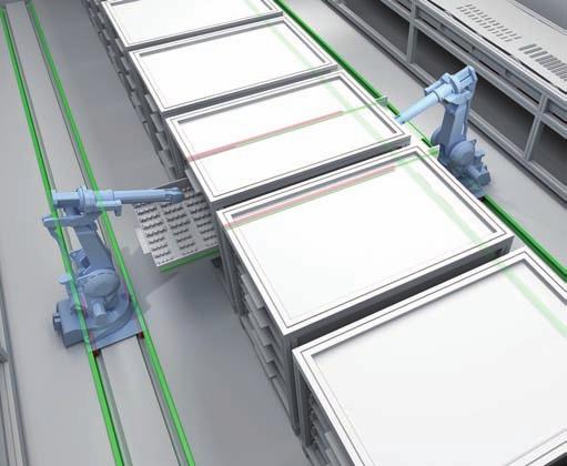
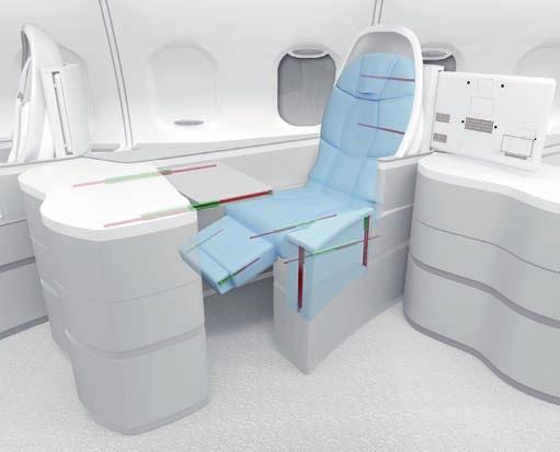
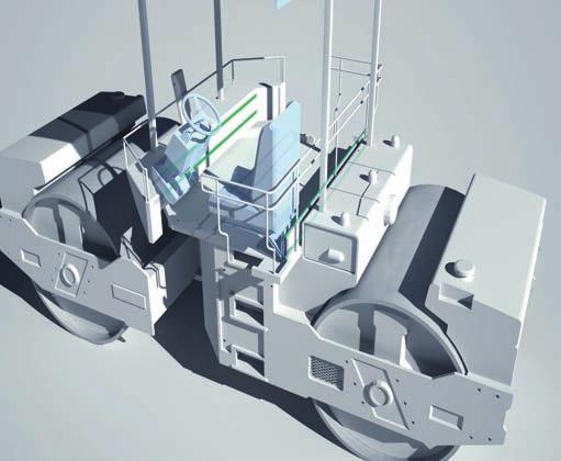
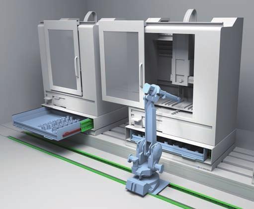
3 Core Competencies Full range of linear rails, telescopic rails and actuators Worldwide presence with branches and distributors Fast delivery all over the world Large technical know-how for applications Standard solutions Collaboration Customization Wide range of products and sizes Linear rails with roller and caged ball bearings Heavy duty telescopic rails Belt or ball screw driven linear actuators Multi-axis systems International know-how in several industries Project consultancy Maximizing performance and cost optimization Special products Research and development of new solutions Technologies dedicated to different sectors Optimal surface treatment Applications Aerospace Railway Logistics Industrial Machines Medical Specialty Vehicles Robotics Packaging

4 Content Mono Rail Mono Rail Technical features overview 1 Product explanation Mono Rails are profile rails for the highest degree of precision 2 Technical data Performance characteristics and notes Mono Rail load capacities Miniature Mono Rail load capacities 3 Product dimensions MRS carriage with flange MRS W carriage without flange MRT W carriage without flange MRR...F rails mounted from below Miniature Mono Rail standard width Miniature Mono Rail large width 4 Accessories Safety equipment and covers Metal cover strip, Flush cap Clamping elements Manual clamp HK Pneumatic clamp MK / MKS Adapter plate 5 Technical instructions Mono Rail precision Miniature Mono Rail precision Mono Rail Radial clearance / preload Miniature Mono Rail Preload Anticorrosive protection, Mono Rail lubrication Miniature Mono Rail lubrication Mono Rail lubrication nipple Friction / displacement resistance Mono Rail loading Miniature Mono Rail loading Mono Rail service life Miniature Mono Rail service life MR-2 MR-5 MR-6 MR-7 MR-8 MR-9 MR-10 MR-11 MR-12 MR-13 MR-14 MR-16 MR-17 MR-18 MR-19 MR-20 MR-21 MR-22 MR-23 MR-24 MR-25 MR-26 MR-28 MR-29 MR-30 MR-31 MR-32 MR-34
5 Mono Rail installation instructions MR-35 Miniature Mono Rail installation instructions MR-37 Installation examples MR-42 Ordering key Ordering key with explanations MR-43


6 Technical features overview Reference Section Shape of rail Hardened raceways Self-alignment Slider Anticorrosion Family Product Balls Rollers Compact Rail TLC KLC ULC +++ **** X-Rail TEX TES UEX UES +++ Available in stainless steel SN ++ **** Easyslide SNK + **** MR - Mono Rail MMR - **** Curviline CKR CVR CKRH CVRH CKRX CVRX + **** Available in stainless steel Sys SYS1 ++ SYS2 ++ **** **** Prismatic Rail P +++ The information shown must be verifi ed for the specifi c application. For a complete view of technical data, please consult our catalogs on * The maximum value is defi ned by the application. ** A longer stroke is available for jointed versions. *** C 50 **** For more information, please contact Rollon.
![Size Max. load capacity per slider [N] Max. dynamic load capacity [N] C 100 Massimo momento [Nm] C O rad C O ax M x M y M z Max. rail length Max. running speed* [m/s] Max.](/docs-images/84/91035786/images/7-0.jpg "acceleration [m/s² ] Operating temperature 18-28-35-43-63 15000 10000 36600 350 689 1830 4080** 9 20-20 C/+120 C 20-30-45 1740 935 **** 3120 1.")
7 Size Max. load capacity per slider [N] Max. dynamic load capacity [N] C 100 Massimo momento [Nm] C O rad C O ax M x M y M z Max. rail length Max. running speed* [m/s] Max. acceleration [m/s² ] Operating temperature ** C/+120 C **** C/+100 C TEX-UEX -20 C/+120 C TES-UES , ,8-20 C/+130 C ** 1,5-20 C/+70 C *** ** 3, C/+60 C ,7 45,7 45,7 1000** C/+80 C 16, **** , C/+80 C ** C/+60 C ** C/+60 C ** C/+80 C C Orad M y M x M zs M zd C Oax

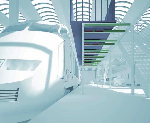
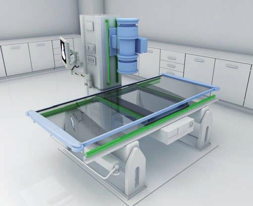
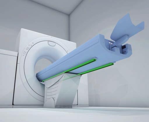
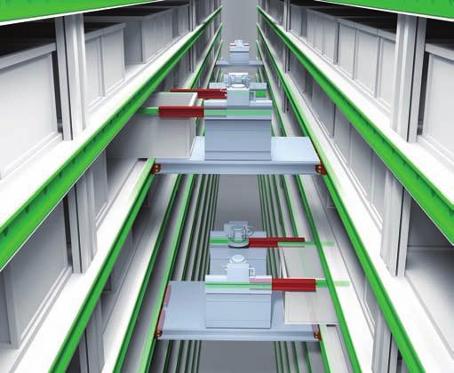
8 1 Product explanation Product explanation Mono Rails are profile rails for the highest degree of precision Fig. 1 The running grooves are ground in semicircular profi le and have a contact angle of 45 in X-arrangement so that the same load capacity is guaranteed in all principle directions. Use of large steel balls enables high load and moment capacities. All carriages in size 55 are equipped with ball chains. The most important characteristics: X-arrangement with 2-point contact of the raceways Uniform loading capacity in all main directions High ability for self-regulating Small differential slip in comparison to 4-point contact Very quiet running and low operating noise Low maintenance due to advanced lubrication chamber Small displacement force in preload compared to 4-point contact Mono Rail profi le rails meet the market standard and can replace linear rails of the same design from other manufacturers while maintaining the main dimensions Miniature Mono Rails available in a standard or large version Miniature Mono Rail available in Martensite stainless steel. Preferred areas of application: Construction and machine technology ( safety doors, feeding ) Packaging machines Special purpose machinery Logistics ( e.g., handling units ) Medical technology ( e.g., X-ray equipment, hospital gurneys ) Semiconductors and electronics industry MR-2

9 Mono Rail MRS Standard carriage with fl ange. Fig. 2 MRS...W / MRT...W Carriage without fl ange, also called block. Available in two different heights. MRT is the lower version. Fig.3 MRS...L Carriage in long version for holding larger loads. MRS...L is the version with fl ange. Fig. 4 MRS...LW Carriage in long version without fl ange. Fig. 5 MR-3


10 1 Product explanation MRT...SW Carriage without fl ange in short version for lower loads with equally high precision. Fig. 6 MRR...F Guide rail MRR...F for bolting from below with threaded holes. Design with smooth surface without bevels. Fig. 7 Standard width Compact technology and high performance in its smallest structural shape. Large width Wide miniature profi le rails, with a compact size, allow the acceptance of higher forces and moments. Especially suited for single rail applications. Fig. 8 Fig. 9 MR-4

11 Mono Rail Technical data Rail End seal Self-lubricating element Redirection Side seal Slider body Lubrication nipple Fig. 10 Performance characteristics: Mono Rail available sizes: 15, 20, 25, 30, 35, 45, 55 Standard version Miniature Mono Rail available sizes: 7, 9, 12, 15 Large version Miniature Mono Rail available sizes: 9, 12, 15 Max. operating speed: 3.5 m/s ( in/s ) ( depending on application ) Max. operating temperature: +80 C (+176 F ) ( depending on application ) Available rail lengths up to approx. 4,000 mm ( in ) for Mono Rail ( see Ordering key, Table 45) Four preload classes for Mono Rail: G1, K0, K1, K2 Three precision classes: N, H, P Three preload classes for the Miniature Mono Rails: V0, VS, V1 Lengths for single rails are available up to 1,000mm (39.37 in) for the Miniature Mono Rail Remarks: Combining rails is possible ( joining ) The fi xing holes on the carriages with fl ange can also be used as through holes for fastening from below. Here, the reduction in size of the screw diameter must be observed Various surface coatings on request Manual and pneumatic clamping elements available as accessories. Depending on the height of the carriage, additional adapter plates must be used Dimensions H 2 and L of the carriage change when using metal defl ectors and other seals. Refer to Sec. 4 Accessories, pg. MR-15f The carriages in size 55 are equipped with ball chains Primary lubricated systems have an increased displacement resistance MR-5
![2 Technical data Mono Rail load capacities C 0ax M x M z C 0rad M y Fig. 11 Type Load capacities [N] Static moments [Nm] Type Load capacities [N] Static moments [Nm] dyn. C stat.](/docs-images/84/91035786/images/12-0.jpg "C 0rad M x M y M z stat. C 0ax dyn. C stat. C 0rad M x M y M z stat.")
12 2 Technical data Mono Rail load capacities C 0ax M x M z C 0rad M y Fig. 11 Type Load capacities [N] Static moments [Nm] Type Load capacities [N] Static moments [Nm] dyn. C stat. C 0rad M x M y M z stat. C 0ax dyn. C stat. C 0rad M x M y M z stat. C 0ax MRS15 MRS15W MRT15W MRS30 MRS30W MRT30W MRT15SW MRT30SW MRS20 MRS20W MRT20W MRS30L MRS30LW MRT20SW MRS20L MRS20LW MRS35 MRS35W MRT35W MRT35SW MRS25 MRS25W MRT25W MRS35L MRS35LW MRT25SW MRS25L MRS25LW Tab. 1 MRS45 MRS45W MRT45W MRS45L MRS45LW MCS55 MCS55W MCS55L Tab. 2 MR-6
13 Mono Rail Miniature Mono Rail load capacities Standard width M y M x C 0 M z C 0 C 0 Fig. 12 Type Load capacities [N] Static moments [Nm] dyn. C 100 stat. C 0 M x M y M z MR07MN MR09MN MR12MN MR15MN Tab. 3 Large width M y M x C 0 M z C 0 C 0 Fig. 13 Type Load capacities [N] Static moments [Nm] dyn. C 100 stat. C 0 M x M y M z MR09WN MR12WN MR15WN Tab. 4 MR-7
14 3 Product dimensions Product dimensions MRS carriage with flange L 2 L* L 1 P 1 W P 2 S D H 1 H H 2 * g 1 g 2 M (4 Threads) P (Hole pitch) d L 3 W 2 W 1 T (Lubrication nipple) * Dimensions H 2 and L change when using end and side seals (see pg. MR-15, Tab. 15). Fig. 14 Type System Slider MRS Weight [kg] Rail MRR Weight [kg/m] H W W 2 H 2 L P 2 P 1 M g 2 L 1 L 2 T S W 1 H 1 P d D g 1 L 3 * MRS , M , MRS M6 9 7 MRS20L MRS M8 7.8 MRS25L M6 x 1 MRS MRS30L M10 MRS , MRS35L MRS M M8 x MRS45L * Only applies when using max. rail lengths ( see Ordering key) Tab. 5 Type System Slider MCS Weight [kg] Rail MRC Weight [kg/m] H W W 2 H 2 L P 2 P 1 M g 2 L 1 L 2 T S W 1 H 1 P d D g 1 L 3 * MCS ,5 12, M M8 x 1 20 MCS55L * Only applies when using max. rail lengths ( see Ordering key) Tab. 6 MR-8
15 Mono Rail MRS W carriage without flange L 2 L* L 1 P 1 W P 2 S D H 1 H 2 * H g 2 g 1 M (4 Threads) P (Hole pitch) d L 3 W 2 W 1 T (Lubrication nipple) * Dimensions H 2 and L change when using end and side seals (see pg. MR-15, Tab. 15). Fig. 15 Type System Slider MRS Weight [kg] Rail MRR Weight [kg/m] H W W 2 H 2 L P 2 P 1 M g 2 L 1 L 2 T S W 1 H 1 P d D g 1 L 3 * MRS15W , M , MRS20W M5 8 7 MRS20LW MRS25W M MRS25LW M6 x 1 MRS30W MRS30LW M MRS35W , MRS35LW MRS45W M M8 x MRS45LW * Only applies when using max. rail lengths ( see Ordering key) Tab. 7 Type System Slider MCS Weight [kg] Rail MRC Weight [kg/m] H W W 2 H 2 L P 2 P 1 M g 2 L 1 L 2 T S W 1 H 1 P d D g 1 L 3 * MCS55W M M8 x * Only applies when using max. rail lengths ( see Ordering key) Tab. 8 MR-9
16 3 Product dimensions MRT W carriage without flange L 2 L* L 1 P 1 L 2 L* L 1 = = W P 2 D g 2 H 1 H H 2 * g 1 S M (4 Threads) M (2 Threads) d W 2 W 1 P (Hole pitch) L 3 T (Lubrication nipple) * Dimensions H 2 and L change when using end and side seals (see pg. MR-15, Tab. 15). Fig. 16 Type System Slider MRT Weight [kg] Rail MRR Weight [kg/m] H W W 2 H 2 L P 2 P 1 M g 2 L 1 L 2 T S W 1 H 1 P d D g 1 L 3 * MRT15W M MRT15SW MRT20W M5 7 5 MRT20SW MRT25W M MRT25SW M6 x 1 MRT30W MRT30SW M MRT35W MRT35SW MRT45W M M8 x * Only applies when using max. rail lengths ( see Ordering key) Tab. 9 MR-10
17 3 Product dimensions Mono Rail MRR...F rails mounted from below g 1 H 1 L 3 P (Hole pitch) F (Threads) W 1 Fig. 17 Rail type W 1 H 1 L 3 * P F g 1 MRR15...F M5 8 MRR20...F M6 MRR25...F MRR30...F M8 MRR35...F MRR45...F M12 24 Tab. 10 * Only applies when using max. rail lengths ( see Ordering key ) MR-11
18 3 Product dimensions Miniature Mono Rail standard width Fig. 18 Type System H W W 2 H 2 MR07MN MR09MN MR12MN MR15MN Tab. 11 Type Slider Rail L P 2 P 1 M g 2 L 1 T S Ø Weight [kg] W 1 H 1 P d D g 1 Weight [kg/m] MR07MN M MR09MN M MR12MN M MR15MN M Tab. 12 MR-12
19 Mono Rail Miniature Mono Rail large width MR15W Fig. 19 Type System H W W 2 H 2 MR09WN MR12WN MR15WN Tab. 13 Type Slider Rail L P 2 P 1 M g 2 L 1 T S Ø Weight [kg] W 1 H 1 P P 3 d D g 1 Weight [kg/m] MR09WN M MR12WN M MR15WN M Tab. 14 MR-13
20 4 Accessories Accessories Safety equipment and covers End seal Carriages of Mono Rail profi le rails are equipped with end seals for contamination protection as standard. End seal Side seal Carriages are equipped with side seals to prevent permeation of contaminates. No side seals are available for carriages in long or short version (...SW/...L/...LW). Fig. 20 Side seal Fig. 21 MR-14
21 Mono Rail Seal variants: A: Carriage with end and side seal Changes in fl oor clearance and length of sliders by corresponding seal variant Seal variant A A Slider type 1 Size Changed dimension H 2 * MRS MRS...W MRT...W Changed length L* MCS MCS...W MRS...L MRS...LW MCS...L MRT...SW No side seals are available for carriages in long or short version (...SW/...L/...LW) Tab. 15 * For comparison see Chapter 3 Product dimensions, pg. MR-8ff MR-15
22 4 Accessories Metal cover strip A rail cover strip made of corrosion resistant steel is available to improve the seal after guide rail installation. The metal cover strip is 0.3 mm wide and can have a maximum length of 50 m. Cover strip Handle 30 Size Width Tab. 16 Rail end clamp Fig. 22 Flush cap Metal debris and other foreign substance can collect in the fi xing holes of the rails and thus end up the carriage. To prevent penetration of contamination in the carriage, the fi xing holes should be capped with perforated caps fl ush with the rail surface. Flush caps are made of wear and oil resistant synthetic resin. Various sizes of perforated caps for the counter sunk holes for hexagon socket bolts M3 to M22 are included as standard in the scope of supply. Flush caps are driven in fl ush with the rail surface with light hammer taps using a fl at piece of metal (see fi g. 23). Plastic hammer Flat piece of metal Fig. 23 MR-16
23 Mono Rail Clamping elements Mono Rail profi le rails can be secured with manual or pneumatic clamping elements. Areas of application are: Table cross beams and sliding beds Width adjustment, stops Positioning of optical equipment and measuring tables Manual clamp elements HK The HK series is a manually activated clamping element. Contact profi les press synchronously on the free surfaces of the profi le rail by using the freely adjustable clamping lever. The fl oating mounted contact profi les guarantee symmetrical introduction of force on the guide rail. Special characteristics of the clamping elements HK: Simple and safe design Floating contact profi le Precise positioning Holding force up to 2,000 N Variants: An additional adapter plate must be used depending on the height of the carriage ( see pg. MR-20, tab. 19 ). Activation: Standard with hand lever, further activation options, e.g. using DIN 912 screw, possible on request. Pneumatic clamp elements MK / MKS The patented wedge slide gear puts into effect high holding forces. The pressurised medium moves the wedge slide gear in the longitudinal direction. Contact profi les press with high force on the free surfaces of the profi le rail by the resulting cross movement. MK is an element that closes with pneumatic pressure. The custom design MKS closes with spring energy storage and is opened via air impingement. Special characteristics of clamp elements MK / MKS: Short shape High clamp forces Precise positioning High axial and horizontal rigidity Areas of application of MK: Positioning axes Setting vertical axes Positioning lifting gear Clamping machine tables Variants: An additional adapter plate must be used depending on the height of the carriage ( see pg. MR-20, tab. 20 ). Connection options: The basic MK / MKS series versions are equipped with air connections on both sides, i.e. the factory default settings air connections and the ventilation fi lter can be exchanged to the opposite side surfaces. Custom design MKS opens with impingement of an air pressure of > 5.5 bar. Areas of application of MKS: Clamping with drop in pressure (Normally Open) Clamping without power required (Normally Closed) MR-17
24 4 Accessories Manual clamp HK Adapter plate P 2 M (4 Threads) D* H W H 2 g 1 H 1 H 3 L P 1 W 1 W 2 * Changed dimensions when using the adapter plate, see pg. MR-20, tab. 19 Fig. 24 Type Size Holding force Tightening torque Dimensions M [N] [Nm] H H 1 H 2 H 3 W W 1 W 2 L P 1 P 2 g 1 HK1501A M HK2006A M HK2501A HK2514A M6 HK3001A HK3501A M HK4501A M10 HK5501A M14 Tab. 17 MR-18
25 Mono Rail Pneumatic clamp MK / MKS Adapter plate P 2 M (4 Threads) W W 1 H 2 P 3 D* H B 4 L 1 P 1 L g 1 W 2 Q * Changed dimensions when using the adapter plate, see pg. MR-20, tab. 20 Fig. 25 Type Size MK holding force MK / MKS 1501A MK / MKS 2001A MK / MKS 2501A [N] MKS holding force [N] Dimensions H H 2 W W 1 W 2 B 4 L 1 * L P 1 P 2 P 3 Q [ ] M M M6 g 1 M MK / MKS 3001A MK / MKS 3501A M8 MK / MKS 4501A MK / MKS 5501A * Only for model MKS M10 Tab. 18 MR-19
26 4 Accessories Adapter plate For HK clamps Clamp Size Slider type Adapter plate D HK1501A 15 HK2006A 20 HK2514A 25 HK2501A HK3001A 30 HK3501A 35 HK4501A 45 On request 55 HK5501A MRS, MRT...W, MRT...SW - 24 MRS...W PHK MRT...W, MRT...SW - 28 MRS, MRS...L, MRS...W, MRS...LW PHK MRT...W, MRT...SW - 33 MRS, MRS...L, - 36 MRS...W, MRS...LW PHK MRS, MRS...L, MRT...W, MRT...SW - 42 MRS...W, MRS...LW PHK MRS, MRS...L, MRT...W, MRT...SW - 48 MRS...W, MRS...LW PMK MRS, MRS...L, MRT...W - 60 MRS...W, MRS...LW PHK MCS, MCS...L - 70 MCS...W PHK Tab. 19 For MK / MKS clamps Clamp Size Slider type Adapter plate D MK / MKS 1501A MK / MKS 2001A On request MK / MKS 2501A MK / MKS 3001A MK / MKS 3501A MK / MKS 4501A On request MK / MKS 5501A MR MRS, MRT...W, MRT...SW - 24 MRS...W PMK MRT...W, MRT...SW - 28 MRS, MRS...L, MRS...W, MRS...LW PMK MRT...W, MRT...SW - 33 MRS, MRS...L, MRZ - 36 MRS...W, MRS...LW PMK MRS, MRS...L, MRT...W, MRT...SW - 42 MRS...W, MRS...LW PMK MRS, MRS...L, MRT...W, MRT...SW - 48 MRS...W, MRS...LW PMK MRS, MRS...L, MRT...W - 60 MRS...W, MRS...LW PMK MCS, MCS...L - 70 MCS...W PMK Tab. 20
27 Mono Rail Technical instructions Mono Rail precision Precision means the guide accuracy or the maximal deviation of the carriage based on the side and support surfaces during the movement along the rails. C D C D H H A W B A W B Fig. 26 Precision class Height tolerance H Side tolerance W Height difference (Δ H) Width difference (Δ W) Guide accuracy of raceway C based on surface A Normal [N] High [H] Precise [P] ± 0.1 ± to ,03 0,02 0,01 ΔC see graph in fig. 27 Guide accuracy of raceway D based on surface B ΔD see graph in fig. 27 Tab. 21 Δ C (μm) Δ D (μm) Normal (N) Norm Hoch High (H) Präz Precise (P) Schienenlänge Rail length (mm) (mm) Fig. 27 MR-21

28 5 Technical instructions Miniature Mono Rail precision There are three precision classes to choose from for the Mono Rail Miniature profi le rails: Classes P, H, and N are manufactured. P H P W2 Fig. 28 Precision classes Precision P [μm] High H [μm] Normal N [μm] H Tolerance of height H ± 10 ± 20 ± 40 ΔH Permissible height difference of different carriages at the same position on the rail W 2 Tolerance of width W 2 ± 15 ± 25 ± 40 ΔW 2 Permissible width difference of different carriages at the same position on the rail Tab. 22 Running accuracy Running accuracy (parallelism) μm mm Length of guide rail Fig. 29 MR-22
29 Mono Rail Mono Rail Radial clearance / preload Radial clearance describes the value for the radial movement of the carriage at a constant vertical load, while the carriage moves in longitudinal direction. Fig. 30 Preload is defi ned as an effective load on the rolling element in the interior of the carriage in order to remove an existing clearance or to increase the rigidity. The Mono Rail profi le rails are available in the four different preload classes G1, K0, K1 and K2 ( see tab. 23 ). The preload infl uences the rigidity, precision and torque resistance and also affects the service life and displacement force. The radial clearance for the respective preload classes are listed in table 24. Degree of preload Preload class Preload With clearance G1 0 No clearance K0 0 Small preload K1 0,02 x C* Average preload K2 0,05 x C* * C is the dynamic load capacity, see pg. MR-9, tab. 1f Tab. 23 Size Radial clearance of the preload classes [μm] G1 K0 K1 K2 Impact free movement, compensation of assembly tolerances Impact free and easy movement Small moments, one rail application, low vibrations Average vibrations and moments, light impacts to to to to to to to to to to to to to to to to to to to to to to to to to to to to -29 Tab. 24 MR-23
30 5 Technical instructions Miniature Mono Rail Preload The Mono Rail Miniature profi le rails are available in the three different preload classes V 0, V S and V 1 (see table 25). The preload infl uences the rigidity, precision and torque resistance and also affects the product service life and displacement force. Type Small clearance Very quiet running Preload classes Standard Very quiet and precise running Small preload High rigidity, vibration reduced, high precision, good load balance V 0 [μm] V S [μm] V 1 [μm] MR07 from +5 to +2 from +1 to -2 from -2 to -4 MR09 from +5 to +2 from +2 to -2 from -2 to -5 MR12 from +6 to +2 from +2 to -2 from -2 to -5 MR15 from +7 to +2 from +2 to -3 from -2 to -6 Tab. 25 MR-24
31 Mono Rail Anticorrosive protection There are numerous application-specifi c surface treatments available for profi le rails of the Mono Rail product family. For more information please contact Rollon technical support. All linear rails of the Miniature Mono Rail series are made of stainless steel. Mono Rail lubrication Profi le rails must generally be lubricated before commissioning. They can be lubricated with oil or grease. The correct lubricant selection has a large infl uence on the service life and the function of the profi le rail, insuffi cient lubrication and tribocorrosion can ultimately lead to total failure. As well as reducing friction and wear, lubricants also serve as sealant, noise damper and corrosion protection for the linear guide. Different lubricants for special applications are available upon request. For more information please contact Rollon technical support. Important instructions for lubrication Mono Rail profi le rails must be lubricated for operation. The carriage must be moved back and forth during lubrication. The lubricant is inserted through a lubrication nipple. There should be a thin fi lm of lubricant on the rail surface at all times. Please inform us in advance if the guides are to be used in acid or base containing environments or in clean rooms. Primary lubricated systems have an increased displacement resistance. Please contact Rollon technical support if the rail will be oriented vertically. If the stroke is <2 or >15 times the carriage length, the lubrication intervals should be shortened. Grease lubrication We recommend the use of a lithium emulsifi ed lubricant NLGI Class 2 for lubrication. Oil lubrication We recommend a synthetic oil for operating temperatures between 0 C and +70 C. For application-specifi c custom lubrication, please contact Rollon technical support. Relubrication Relubrication of the system must be done before the lubricant used is dirty or shows discolouration. Relubrication is performed at operating temperature. The carriage must be moved back and forth during relubrication. If the stroke is <2 or >15 times the carriage length, the lubrication intervals should be more often. Lubrication intervals Operating speed, stroke length and ambient conditions infl uence the selection of time between lubrication intervals. Establishing a safe lubrication interval is based exclusively on the experienced practiced values determined on site. However, a lubrication interval should not be longer than one year in any case. MR-25

32 5 Technical instructions Miniature Mono Rail lubrication Function The contact points between ball and track are separated from each other by a microscopically thin oil fi lm. The lubrication effects: Reduction of friction Reduction of wear Corrosion protection Better thermal distribution and therefore increased of service life Fig. 31 Important instructions for lubrication Mono Rail Miniature profi le rails must be lubricated for operation. The carriage must be moved back and forth during lubrication. The lubricant can also be applied to the tracks. The lubricant can be injected into the lubrication holes on both sides of the carriage. There should be a thin fi lm of lubricant on the rail surface at all times. Please inform us in advance if the guides are to be used in acid or base containing environments or in clean rooms. Please contact the sales department if the oil lubrication should be used for vertical use of the guide. If the stroke is < 2 or > 15 times the carriage length, the lubrication intervals should be more often. Type First lubrication [cm 3 ] MR07MN 0.12 MR09MN 0.23 MR12MN 0.41 MR15MN 0.78 Tab. 26 Type First lubrication [cm 3 ] MR09WN 0.30 MR12WN 0.52 MR15WN 0.87 Tab. 27 MR-26
33 Mono Rail Grease lubrication When using grease lubrication, we recommend synthetic-oil based lithium grease with a viscosity according to ISO VG 32 to ISO VG 100. Oil lubrication We recommend CLP or CGLP synthetic oil conforming to DIN or HLP to DIN and a viscosity range conforming to ISO VG 32 to ISO VG 100 for operating temperatures between 0 C and +70 C. We recommend a viscosity according to ISO VG 10 for use at low temperatures. For application-specifi c special lubrication please contact Rollon technical support. mm2 ISO VG 10 = Viscosity of 10 s at 40 C Lubrication intervals Operating speed, stroke length and ambient conditions infl uence the selection of time between lubrication intervals. Establishing a safe lubrication interval is based exclusively on the experienced practiced values determined on site. However, a lubrication interval should not be longer than one year in any case. Relubrication Relubrication of the system must be done before the lubricant used is dirty or shows discolouration. An application of approx. 50 % of the quantity used for fi rst lubrication is suffi cient for relubrication ( see tab. 28). Relubrication is performed at operating temperature. During relubrication, the carriage should be moved back and forth. If the stroke is < 2 or > 15 times the carriage length, the lubrication intervals should be more often. mm 2 ISO VG 32 = Viscosity of 32 s at 40 C mm 2 ISO VG 100 = Viscosity of 100 s at 40 C Fig. 32 Initial lubrication and relubrication Self-lubricating The carriages of the following sizes have a self-lubrication element to extend lubrication intervals. Not self-lubricating The carriages of sizes 35 and 45 are not self-lubricating due to the design. Size Initial lubrication grease Relubrication Initial lubrication oil Size Initial lubrication grease Relubrication Initial lubrication oil [cm 3 ] [cm 3 ] [cm 3 ] [cm 3 ] [cm 3 ] [cm 3 ] Tab. 28 The given lubrication quantities apply to preload K1 and speeds 1 m/s Tab. 29 The given lubrication quantities apply to preload K1 and speeds 1 m/s MR-27
34 5 Technical instructions Mono Rail lubrication nipple The following lubrication nipples are part of the standard delivery: NLA01 Ø 3 x 5 Lubrication nipple Size NLA ,3 NLB NLB02 9,8 16,6 M6 x 6 NLB Tab. 30 Other lubrication nipples, such as lubrication adapters with hose inlet or with quick-coupling, are available on request. Please observe that the thread lengths ( see fi g. 33 ) can be changed when using additional defl ectors and end seals. For more information please contact Rollon technical support. NLB04 16,6 M8 x 6 9,8 Fig. 33 MR-28
35 Mono Rail Friction / displacement resistance Mono Rail profi le rails have a low friction characteristic and thus low displacement resistance. The low start-up friction (breakaway force) is almost identical to the moving friction (running resistance). The displacement resistance is dependent upon several factors: Friction of the sealing system Friction of the balls with each other Friction between balls and redirection Rolling resistance of the balls in the running grooves Resistance of lubricant in the carriage Resistance by contamination in the lubricant Preload for increase of rigidity Moment load Resistance of the seals Type f [N] MRS MRS MRS MRS MRS Coefficient of friction (μ) MRS MCS Tab Loading ratio: (P/C) P: Loading C: Dynamic load capacities 0.2 Fig. 34 Displacement resistance The following formula is used for general approximate calculation of the displacement resistance. Please note that the level of preload or the viscosity of the lubricant used can also infl uence the displacement resistance. F m = μ F + f F m = Displacement resistance ( N ) F = Load ( N ) μ = Coeffi cient of friction f = Resistance of the seals ( N ) Fig. 35 Mono Rail profi le rails have a coeffi cient of friction of approx. μ = MR-29
36 5 Technical instructions Mono Rail loading The given static load capacity for each carriage represents the maximum permissible load value, which if exceeded causes permanent deformations of the raceways and adverse effects of the running properties. Checking the load must be done as follows: - through determination of the simultaneously occurring forces and moments for each carriage - by comparison of these values with the corresponding load capacities. The ratio of the actual load to maximum permissible load may be as large as the reciprocal of the accepted safety factor, S 0, at the most. P 0rad 1 P 0ax 1 M 1 1 M 2 1 M 3 1 C 0rad S 0 C 0ax S 0 M x S 0 M y S 0 M z S 0 Fig. 36 The above formulas are valid for a single load case. If two or more forces are acting simultaneously, please check the following formula: P 0rad P 0ax M 1 M 2 M C 0rad C 0ax M x M y M z 1 S 0 P 0rad C 0rad P 0ax C 0ax = effective radial load (N) = permissible radial load (N) = effective axial load (N) = permissible axial load (N) M 1, M 2, M 3 = external moments ( Nm) M x, M y, M z = maximum permissible moments in the different loading directions (Nm) Fig. 37 Safety factor Operating conditions S 0 Normal operation 1 ~ 2 Loading with vibration or shock effect 2 ~ 3 Loading with strong vibration or impacts 3 Tab. 32 The safety factor S 0 can lie on the lower given limit if the occurring forces can be determined with suffi cient precision. If shock and vibration are present, the higher value should be selected. For dynamic applications higher safety is required. Please contact Rollon technical support. MR-30
37 Mono Rail Miniature Mono Rail loading Static load (P 0 ) and static moment (M 0 ) Permissible static load The permissible static load of the Mono Rail Miniature profi le rail is limited by: Static load of each linear guide Permissible load of the fi xing screws Permissible load of all components used in the surrounding construction Static safety factor, which is required by the corresponding application The equivalent static load and the static moment are the largest load, or the largest moment, which are calculated based on formulas 3 and 4. Static safety factor S 0 When observing the static safety factor S 0 the Mono Rail Miniature profi le rails allow a permissible operation and high running precision as is required for each application. Calculation of the static safety factor S 0 : see fi g. 38 S 0 static safety factor C 0 static load capacity in loading direction (N) P 0 equivalent static load (N) M 0 static moment in loading direction (Nm) M equivalent static moment in loading direction (Nm) Static load capacity C 0 The static load capacity C 0 of ball recirculating guides is defi ned according to DIN 636, Part 2 as the only load which gives a Hertzian stress of 4,200 MPa with the existing lubrication between track and balls in the center of the highest loaded contact surface. Note: In the loading center, there is a permanent deformation of approx 0.01 % of the ball diameter under this load (according to DIN 636, Part 2). S 0 = C 0 / P 0 Formula 1 Operating conditions S 0 S 0 = M 0 / M Formula 2 Normal operation 1 ~ 2 P 0 = F max Formula 3 Loading with vibration or shock effect 2 ~ 3 M 0 = M max Formula 4 High precision and smooth running 3 Fig. 38 MR-31
38 5 Technical instructions Dynamic load capacity C If the dynamic loads work vertically on the last zones with equal size and direction, the calculated service life of the linear guide can theoretically reach 100 km piston travel (as per DIN 636, Part 2). Combined loads in combination with moments If both loads and moments work on the profi le rails, the equivalent dynamic load is calculated with formula 9. According to DIN 636, Part 1, the equivalent load should not exceed ½ C. Equivalent dynamic load and speed With changing load and speed, these must be considered individually since each parameter helps determine the service life. Equivalent dynamic load If only the load changes, the equivalent dynamic load can be calculated with formula 5. Equivalent speed If only the speed changes, the equivalent speed is calculated with formula 6. If speed and load change, the equivalent dynamic load is calculated with formula 7. Combined dynamic load With combined exterior load in an arbitrary angle, the equivalent dynamic load is calculated with formula q P = 3 1 F 1 + q 2 F 2 + q n F n 100 Formula 5 q v = 1 v 1 + q 2 v 2 + q n v n 100 Formula q P = 3 1 v 1 F 1 + q 2 v 2 F 2 + q n v n F n 100 Formula 7 P = F X + F Y Formula 8 M P = F X + F Y + ( 1 M + 2 M + 3 ) C M 0 x M y M z Formula 9 P = equivalent dynamic load (N) q = stroke (in %) F 1 v v F F Y F X C 0 = individual load levels (N) = average speed (m/min) = individual speed levels (m/min) = external dynamic load (N) = external dynamic load vertical (N) = external dynamic load horizontal (N) = static load capacity (N) M 1, M 2, M 3 = external moments (Nm) M x, M y, M z = maximum permissible moments in the different loading directions (Nm) Fig. 39 MR-32
39 Mono Rail Mono Rail service life Calculation of service life: The dynamic load capacity C is a conventional variable used for calculating the service life. This load corresponds to a nominal service life of 50 km. The relationship between calculated service life L km ( in km ), dynamic load capacity C ( in N ) and equivalent load P ( in N ) is given in the formula to the right: C f L km = ( c ) 3 50 km P f i f c = contact factor f i = application coeffi cient Fig. 40 The equivalent load P corresponds in its effects to the sum of the forces and moments working simultaneously on a slider. If these different load components are known, P results from the equation to the right: M P = P 0ax + P 0rad + ( 1 M + 2 M + 3 ) C M 0rad x M y M z Fig. 41 Contact factor f c The contact factor f c refers to applications in which several carriages pass the same rail section. If two or more carriages are moved over the same point on a rail, the static and dynamic loading values must be multiplied with the numbers from the table below: Number of carriages f c Tab. 33 Application coefficient f i The application coeffi cient f i can be understood as the dynamic safety factor. Refer to the table below for the values: Operational conditions Speed f i Neither external impacts nor vibrations Low speed V 15 m/min Light impacts or vibrations Average speed 15 < V 60 m/min Average and high external impacts or vibrations High speed V > 60 m/min Tab. 34 MR-33
40 5 Technical instructions Miniature Mono Rail service life An example of a profi le rail or a lot of identical profi le rails under the same running conditions, which use ordinary materials with normal manufacturer s quality and operating conditions, can reach 90 % of the calculated service life (as per DIN 636 Part 2). By taking 50 km traverse as a basis, the dynamic load capacity is usually 20 % over the values as per DIN. The relationship between the two load capacities can be seen from formulas 10 and 11. Calculation of service life Formulas 12 and 13 are used for calculating the service life, if equivalent dynamic load and average speed are constant. C (50) = 1,26 C (100) Formula 10 C (100) = 0,79 C (50) Formula 11 C 100 L = ( ) Formula 12 P C 100 L L L h = = ( ) 3 Formula 13 2 s n 60 P V m L = service life based on 100,000 (m) L h = service life (h) C = dynamic load capacity (N) P = equivalent dynamic load (N) S = stroke length (m) n = stroke frequency (min -1 ) V m = average speed (m/min) Fig. 42 MR-34
41 Mono Rail Mono Rail installation instructions The given radii and shoulder heights in the table must be observed when assembling rails and carriages on the stop edges to ensure perfect seating of carriages or raceways. Ground surface Sm Sm Hc Hr Sm Ground stop surface Lv Lv Sm Fig. 43 Size Maximum level of incline Maximum height of rail shoulder Maximum height of rail shoulder when using the side seal Maximum height of slider shoulder Required bolt lengths (rails) Sm Hr Hr* Hc Lv M4 x M5 x M6 x M8 x M12 x M14 x 45 Tab. 35 * For use of various seals, see pg. MR-14, fi g. 21ff MR-35
42 5 Technical instructions Assembly precision The maximum permissible deviations of the rail surfaces for assembly are given in the following drawing ( see fi g. 44 ) and the table below ( see tab. 36 ): p1 p2 Fig. 44 Size Permissible tolerance for parallelism p1 [μm] Permissible tolerance for parallelism p2 [μm] K2 K1 K0 G1 K2 K1 K0 G The bolt sizes to be used and optimum tightening torques for rail assembly are listed in the table below ( see tab. 37 ) Tab Bolt Tightening torque M t [Nm] Steel Cast iron Aluminium M M M M M M Tab. 37 MR-36
43 Mono Rail Miniature Mono Rail installation instructions Shoulder heights and radius of stop edges Rounding of the stop edges of the surrounding construction should be r2 made so as to avoid contact with the edges of the carriage and the rail. Please observe the following table with the information on the radius and height of the stop surfaces. E h1 h2 r1 Fig. 45 Dimensions of the stop edges Type h 1 r 1max h 2 r 2max E Type h 1 r 1max h 2 r 2max E MR07M MR09M MR12M MR15M Tab. 38 MR09W MR12W MR15W Tab. 39 Geometric and positional accuracy of the mounting surfaces Inaccuracies of the mounting surface negatively infl uence the running accuracy and reduce the service life of the Mono Rail Miniature profi le rails. If the inaccuracies of the mounting surfaces exceed the values calculated using formulas 14, 15 and 16, the service life is shortened according to formulas 12 und 13. Mounting surface The mounting surface should be ground or milled very fi nely and have a surface roughness of R a 1.6. Reference surface Rail: Both sides of the rails can be used as a reference surface without further marks. Slider: The reference surface is located across from the running side identifi ed with a notch mark. MR-37
44 5 Technical instructions Calculation of the positional accuracy e2 e1 e3 d b Fig. 46 Fig. 47 e1 (mm) = b (mm) f Formula 14 e2 (mm) = d (mm) f Formula 15 e3 (mm) = f Formula 16 Fig. 48 Type V 0, V S V 1 Type V 0, V S V 1 f1 f2 f3 f1 f2 f3 f1 f2 f3 f1 f2 f3 MR07MN MR09MN MR12MN MR15MN Tab. 40 MR09WN MR12WN MR15WN Tab. 41 Tightening torque for fixing screws (Nm) Screw quality 12.9 Steel Cast iron Non-ferrous metal M M M Tab. 42 MR-38
45 Mono Rail Composite rails Guide rails longer than the one part maximum length ( see Ordering key), are put together from two or more rails. When putting guide rails together, be sure that the register marks shown in fi g. 49 are positioning correctly. These are fabricated axisymmetric for parallel application of composite guide rails, unless otherwise specifi ed. Two rails Comp. L Joint A A Several rails Joint Joint marks Comp. L Joint A1 A1 Joint marks Joint Joint A2 A2 Joint marks B1 B1 B2 B2 Joint marks Joint marks Fig. 49 MR-39
46 5 Technical instructions Assembly process Adjacent construction Set screw (slider) Set screw (rail) Sub-construction Fig. 50 Fixing guide rails: ( 1) Whet the assembly surface with a whetstone and also remove burrs, unevenness and dirt ( see fi g. 51 ). Note: All linear guides are preserved with anticorrosion oil at the factory. This protection must be removed before installation. In doing so, please ensure that the surfaces are coated with low-viscosity oil for the purpose of further protection against corrosion. Fig. 51 ( 2 ) Carefully lay the guide rail on the assembly surface ( see fi g. 52 ) and slightly tighten the fi xing screws so that the guide rail lightly touches the assembly surface ( align the guide rail along the shoulder edge of the assembly surface, see fi g. 53 ). Note: The fi xing screws of the linear guide must be clean. Check if the fi xing holes are located in the correct place when you insert the bolts. A forced tightening of a fi xing screw in an offset hole can negatively affect accuracy. Fig. 52 Fig. 53 MR-40
47 Mono Rail ( 3 ) Tighten the thrust bolts on the guide rail until there is close contact on the side stop surface ( see fi g. 54 ). Fig. 54 ( 4 ) Tighten the fi xing screws with a torque wrench to the prescribed torque ( see pg. MR-36, tab. 37). Note: For a high degree of accuracy, the fi xing screws of the guide rail must be tightened in sequence outward from the centre ( see fi g. 55 ). ( 5 ) Assemble the other rails in the same manner to complete the installation of the guide rails. Table assembly: ( 6 ) Set the table carefully on the carriage and tighten the fi xing screws only lightly. ( 7 ) Press the carriage on the main guide side with the thrust bolts against the shoulder edge of the table and position the table. ( 8 ) Tighten the fi xing screws on the main side and the lateral side completely tight to fi nish the installation. Note: To attach the table uniformly, tighten the fi xing screws diagonally ( see fi g. 56 ). This method saves time when straightening the guide rail and makes the manufacture of positioning pins unnecessary, which considerably reduces assembly time Fig. 55 Fig. 56 MR-41
48 5 Technical instructions Installation examples The following drawings illustrate some assembly examples for rail/carriage combinations corresponding to the structure of various machine frames: Example 1: Assembly of carriage and rail on shoulder edges Example 2: Securing carriage and rail using set screws Example 3: Securing carriage and rail using set pressure plates Example 4: Securing carriage and rail using taper gibs Example 5: Securing carriage and rail using bolts Fig. 57 MR-42
49 Mono Rail Ordering key Rail / Mono Rail slider system MRS30W H K1 A F T HC Surface coating for rail optional see pg. MR-25, Anticorrosive protection Joint processed rails optional see pg. MR-39, Composite rails Rails bolted from below, optional see pg. MR-11 Total rail length Number of carriages Seal variants see pg. MR-15f Preload class see pg. MR-23, tab. 23f Precision class see pg. MR-21, tab. 21 Type Ordering example: MRS30W-H-K1-A-HC F-T-NIC Rail composition: 1x3100+1x2860 (only for joint processed rails) Hole pattern: 20-38x80-40//40-35x80-20 (please always indicate the hole pattern separately) Notes on ordering: The rail lengths are always indicated as 5 digits with 0 prefi xes Rail MRR N F T HC Surface coating for rail optional see pg. MR-25, Anticorrosive protection Rail type Size Joint processed rails optional see pg. MR-39, Composite rails Rails bolted from below, optional see pg. MR-11 Precision class see pg. MR-21, tab. 21 Total rail length Ordering example: MRR NF-T-NIC Rail composition: 1x2920+1x3940 (only for joint processed rails) Hole pattern: 10-48x60-30//30-65x60-10 (please always specify the hole pattern separately) Notes on ordering: The rail lengths are always indicated as 5 digits with 0 prefi xes MR-43
50 Ordering key Carriage MRS35 N K0 A HC Type Surface coating for carriage optional Seal variants see pg. MR-15f Preload class see pg. MR-23, tab. 23f Precision class see pg. MR-21, tab. 21 see pg. MR-25, Anticorrosive protection Ordering example: MRS35-N-K0-A-NIC Rail / Miniature Mono Rail slider system MR 15 M N SS 2 V1 P 310 Rail length see tab. 44 and 45 Precision class see pg. MR-22, tab. 22 Preload class see pg. MR-24, tab. 25 Number of sliders on one rail End seal Slider type Rail type see pg. MR-12, tab. 11 / pg. MR-13, tab. 13 Rail width see pg. MR-12, tab. 12 / pg. MR-13, tab. 13 Product type Ordering example: MR15MN-SS-2-V1-P-310 Hole pattern: 15-7 x 40-15, see fi g. 59, tab. 44 / fi g. 60, tab. 45 MR-44
51 Mono Rail Mono Rail hole pattern Rail L 2 + 0,5 mm P L + 3 0,5 mm L 0 Fig. 58 Size Hole pitch P L 2min, L 3min L 2max *, L 3max * L 0max Tab. 43 * Only applies when using max. rail lengths MR-45
52 Ordering key Miniature Mono Rail hole pattern Standard width 0,4 Lateral L 3 0,5 mm + P L + 2 0,5 mm L 0 0,8 mm + Fig. 59 Size L min Hole pitch P L 2, L 3min L 2, L 3max * L max * does not apply to minimum (L min ) and maximum rail length (L max ) 1000 Tab. 44 Large width L3 + 0,5 mm 0,4 Lateral P L + 2 0,5 mm L 0 0,8 mm + Fig. 60 Size L min Hole pitch P L 2, L 3min L 2, L 3max * L max * does not apply to minimum (L min ) and maximum rail length (L max ) 1000 Tab. 45 MR-46
53 Mono Rail Notes MR-47

54 Guides suitable for all applications Railway Medical Logistics


55 Aerospace Special Vehicles Industrial

 316 581 999 www.rollon.nl - info@rollon.")
 (0) 4 74 71 93 30 www.")

 80 67027066 www.")
 1234964024 www.")
 3198 3645 www.rollonbrasil.com.br - info@rollonbrasil.")

56 ROLLON S.p.A. - ITALY Via Trieste 26 I Vimercate (MB) Phone: (+39) infocom@rollon.it Rollon Branches & Rep. Offi ces Distributors Branches: ROLLON GmbH - GERMANY Bonner Strasse D Düsseldorf Phone: (+49) info@rollon.de ROLLON B.V. - NETHERLANDS Ringbaan Zuid DB Zevenaar Phone: (+31) info@rollon.nl Rep. Offices: ROLLON S.p.A. - RUSSIA , Moscow, Varshavskoye shosse 17, building 1 Phone: +7 (495) info@rollon.ru ROLLON S.A.R.L. - FRANCE Les Jardins d Eole, 2 allée des Séquoias F Limonest Phone: (+33) (0) infocom@rollon.fr ROLLON Ltd - CHINA No. 16 Jin Wen Road, China, Shanghai, Phone: info@rollon.cn.com ROLLON Corporation - USA 101 Bilby Road. Suite B Hackettstown, NJ Phone: (+1) info@rolloncorp.com ROLLON India Pvt. Ltd. - INDIA 1st fl oor, Regus Gem Business Centre, 26/1 Hosur Road, Bommanahalli, Bangalore Phone: (+91) info@rollonindia.in ROLLON Ltd - UK The Works 6 West Street Olney Buckinghamshire, United Kingdom, MK46 5 HR Phone: +44 (0) info@rollon.uk.com Regional Manager: ROLLON - SOUTH AMERICA R. Joaquim Floriano, 397, 2o. andar Itaim Bibi , São Paulo, BRASIL Phone: +55 (11) info@rollonbrasil.com ROLLON - JAPAN 3F Shiodome Building, Kaigan, Minato-ku, Tokyo Japan Phone info@rollon.jp Consult the other ranges of products Distributor Actuator Line All addresses of our global sales partners can also be found at The content of this document and its use are subject to the general terms of sale of ROLLON available on the web site Changes and errors expected. The text and images may be used only with our permission. LL_GC_EN_07/17
...components in motion. Miniature Linear Guideways
 ...components in motion Miniature Linear Introduction Miniature linear guideway systems are widely used throughout industry for precise, compact applications. Precise and Stainless The gothic arch shape
MONO RAIL.
 MONO RAIL www.rollon.com About Rollon Development of global business Continual expansion and optimization of the portfolio 1975 Parent company, Rollon S.r.l., founded in Italy 1991 Founding of Rollon GmbH
...components in motion. Linear Guideways
 ...components in motion Linear 3 Linear Technical Information Linear Linear guideways are widely used throughout industry for heavy duty and precise applications. Linear from Automotion Components The
 A LEADING MANUFACTURER IN LINEAR MOTION GERALD SUMMERS is now an authorised distributor of Rollon TEL: 0800 055 6663 E-MAIL: SALES@GERALD-SUMMERS.CO.UK WWW.GERALD-SUMMERS.CO.UK MINIATURE MONO RAIL www.rollon.com
Linear Guideways ov -linear -guidew ays-divider - U pdated
 Linear Guideways ov-linear-guideways-divider - Updated - 11-01-2017 163 Linear Guideways Linear Guideways Introduction L1016 Linear guideways Linear guideways are widely used throughout industry for heavy-duty
Linear Line.
 Linear Line www.rollon.com When you move, we move. RollonSrl was set up in 1975 as a manufacturer of linear motion components. Today Rollon group is a leading name in the design, production and sale of
Telescopic Line. General catalogue English.
 Telescopic Line General catalogue English www.rollon.com When you move. We move Rollon S.p.. was set up in 1975 as a manufacturer of linear motion components. Today Rollon group is a leading name in the
Miniature Ball Rail Systems
 R310EN 2210 (2004.06) The Drive & Control Company 2 Bosch Rexroth AG Linear Motion and Assembly Technologies Miniature-BRS R310EN 2210 (2004.06) Linear Motion Systems Ball Rail System Standard Ball Rail
Easyslide FrontespizioEasyslide.indd 1 21/05/ :26:17
 Easyslide When you move. We move Rollon S.p.A. was founded in 1975 as a manufacturer of linear motion components. Today Rollon group is a leading name in the design, production, and sale of linear rails,
Easy Slide Rails ov -easy_slide_divider - U pdated
 Easy Slide Rails ov-easy_slide_divider - Updated - 18-09-2017 163 Easy Slide Rails Easy Slide Rails Introduction The Easy Slide family of linear rails have a compact cross-section and low-friction movement.
Any reproduction, even partial, is allowed only by written permission by Rollco.
 EASYSLIDE Every care has been taken to ensure the accuracy of the information contained in this catalogue, but no liability can be accepted for any errors or omissions. We reserve the right to make changes
...components in motion. Easy Rail
 ...components in motion Easy Rail Easy Rail Introduction The Easy Rail family have a compact cross-section and low-friction movement. Robust and Long Service Life Easy Rail s range of cross-sectional rail
Courtesy of CMA/Flodyne/Hydradyne Motion Control Hydraulic Pneumatic Electrical Mechanical (800)
") 01_1 Miniature st Headline_36 Ball Rail pt/14.4 Systems mm second line 2 Linear Motion and Assembly Technologies Miniature Ball Rail Systems Ball Rail Systems Roller Rail Systems Linear Bushings and Shafts
01_1 Miniature st Headline_36 Ball Rail pt/14.4 Systems mm second line 2 Linear Motion and Assembly Technologies Miniature Ball Rail Systems Ball Rail Systems Roller Rail Systems Linear Bushings and Shafts
Curviline FrontespizioCurviline.indd 1 07/10/ :24:20
 Curviline When you move. We move Rollon S.p.A. was founded in 1975 as a manufacturer of linear motion components. Today Rollon group is a leading name in the design, production, and sale of linear rails,
EASY RAIL.
 EASY RAIL www.rollon.com About Rollon Development of global business Continual expansion and optimization of the portfolio 1975 Parent company, Rollon S.r.l., founded in Italy 1991 Founding of Rollon GmbH
Ball Rail Systems RE / The Drive & Control Company
 Ball Rail Systems RE 82 202/2002-12 The Drive & Control Company Rexroth Linear Motion Technology Ball Rail Systems Roller Rail Systems Standard Ball Rail Systems Super Ball Rail Systems Ball Rail Systems
 UNILINE www.motiontech.com.au bout Rollon Development of global business Continual expansion and optimization of the portfolio 1975 Parent company, Rollon S.r.l., founded in Italy 1991 Founding of Rollon
Profi le rail guides LLR
 Profi le rail guides LLR Content The SKF brand now stands for more than ever before, and means more to you as a valued customer. While SKF maintains its leadership as the hallmark of quality bearings throughout
TELESCOPIC RAIL HEAVY
 TELESCOPIC RAIL HEAVY Every care has been taken to ensure the accuracy of the information contained in this catalogue, but no liability can be accepted for any errors or omissions. We reserve the right
R310EN 2211 ( ) The Drive & Control Company
 The Drive & Control Company") eline Ball Rail Systems R310EN 2211 (2006.04) The Drive & Control Company Bosch Rexroth AG Linear Motion and Assembly Technologies Ball Rail Systems Roller Rail Systems Linear Bushings and Shafts Ball
eline Ball Rail Systems R310EN 2211 (2006.04) The Drive & Control Company Bosch Rexroth AG Linear Motion and Assembly Technologies Ball Rail Systems Roller Rail Systems Linear Bushings and Shafts Ball
 A LEADING MANUFACTURER IN LINEAR MOTION GERALD SUMMERS is now an authorised distributor of Rollon TEL: 0800 055 6663 E-MAIL: SALES@GERALD-SUMMERS.CO.UK WWW.GERALD-SUMMERS.CO.UK CURVILINE www.rollon.com
CURVILINE.
 CURVILINE www.rollon.com About Rollon Development of global business Continual expansion and optimization of the portfolio 1975 Parent company, Rollon S.r.l., founded in Italy 1991 Founding of Rollon GmbH
Mono Rail +
 Mono + www.rollon.com Content Mono + Technical features overview 1 Product explanation Profile rails for the highest degree of precision 2 Technical data Performance characteristics and notes Load capacities
Inner block. Grease nipple. Fig.1 Structure of LM Guide Actuator Model KR
 LM Guide ctuator Model LM Guide + all Screw = Integral-structure ctuator Stopper Housing all screw Inner block Grease nipple Outer rail earing (supported side) Housing Stopper Double-row ball circuit earing
MINIRAIL Profiled miniature guideway
 MINIRAIL Profiled miniature guideway Table of Contents 1 Product overview and technical informations MINIRAIL a range of high-precision products.... 2 MINIRAIL overview accuracy classes:.... 3 MINIRAIL
R310EN 2302 ( ) The Drive & Control Company
 The Drive & Control Company") R31EN 232 (26.4) The Drive & Control Company Bosch Rexroth AG Linear Motion and Assembly Technologies Ball Rail Systems Linear Bushings and Shafts Ball Screw Drives Linear Motion Systems Basic Mechanical
R31EN 232 (26.4) The Drive & Control Company Bosch Rexroth AG Linear Motion and Assembly Technologies Ball Rail Systems Linear Bushings and Shafts Ball Screw Drives Linear Motion Systems Basic Mechanical
Contents. Page. 1. Product description. 2. The AXC line of linear axes. 3. AXLT line of linear tables. AXC and AXS product overview...
 SNR Industry Contents Page 3 1. Product description AXC and AXS product overview... 6-8 Dynamic load ratings of the linear motion systems... 9 Compact modules... 10-11 Linear tables... 12 Telescopic axes...
TELESCOPIC RAIL.
 TEESCOPIC RAI www.rollon.com About Rollon Development of global business Continual expansion and optimization of the portfolio 1975 Parent company, Rollon S.r.l., founded in Italy 1991 Founding of Rollon
INDEX EASY RAIL: THE SOLUTION IS EASY...D4 EXAMPLES OF LOAD CAPACITIES...D5 ORDER CODES...D6 MOUNTING EXAMPLES...D7 TECHNICAL DATA...
 INDEX EASY RAIL: THE SOLUTION IS EASY...D4 EXAMPLES OF LOAD CAPACITIES...D5 ORDER CODES...D6 MOUNTING EXAMPLES...D7 TECHNICAL DATA...D8 STANDARD CONFIGURATIONS...D10 VERIFICATION UNDER STATIC LOAD...D12
Cross Roller Guide/Ball Guide General Catalog
 General Catalog A Product Descriptions Features and Types... A7-2 Features of the.. A7-2 Structure and Features... A7-2 Types of the.. A7-3 Types and Features... A7-3 Point of Selection... A7-4 Rated Load
TELESCOPIC RAIL.
 TEESCOPIC RAI www.rollon.com About Rollon Development of global business Continual expansion and optimization of the portfolio 1975 Parent company, Rollon S.r.l., founded in Italy 1991 Founding of Rollon
Uniline System FrontespizioUnilineSystem.indd 1 22/11/ :32:41
 Uniline ystem 1 Uniline series Uniline series Uniline series description ig. 1 Uniline is a family of ready-to-install linear actuators. They consist of internal ompact Rail roller sliders and steel-reinforced
X-Rail FrontespizioXRai.indd 1 07/10/ :30:14
 X-Rail 1 Product explanation Product explanation X-Rail: orrosion resistant or zinc-plated steel linear bearings ig. 1 X-Rail is the product family of roller embossed guide rails for applications in which
Ball. Ball cage. Fig.1 Structure of Caged Ball LM Guide Actuator Model SKR
 Caged all LM Guide Actuator Model Inner block all screw shaft Grease nipple Outer rail all cage all Structure and Features Fig.1 Structure of Caged all LM Guide Actuator Model Caged all LM Guide Actuator
Slotted nut NMG. Housing nut GWR. Bosch Rexroth AG. for economical constructions. a min. 0,3. M A = tightening torque of slotted nut.
 R310EN 3301 (2009.08) Precision Ball Screw Assemblies Bosch Rexroth AG 113 Slotted nut NMG for economical constructions B D d d1 b M A = tightening torque of slotted nut a min. 0,3 Polyamide insert Designation
SNR, YOUR GUIDE TO LINEAR MODULES
 SNR, YOUR GUIDE TO LINEAR MODULES A bearing manufacturer known across the world For almost a century NTN-SNR has been focusing on the development, design and manufacture of bearings. Today NTN-SNR has
Any reproduction, even partial, is allowed only by written permission by Rollco.
 LINEAR UNIT E-SMART Every care has been taken to ensure the accuracy of the information contained in this catalogue, but no liability can be accepted for any errors or omissions. We reserve the right to
Profile rail guides LLT
 Profile rail guides LLT Contents The SKF brand now stands for more than ever before, and means more to you as a valued customer. While SKF maintains its leadership as the hallmark of quality bearings throughout
Features of the LM Guide
 Features of the Functions Required for Linear Guide Surface Large permissible load Highly rigid in all directions High positioning repeatability Running accuracy can be obtained easily High accuracy can
carriages to carry the load (taking into account any moment loads). Unlike the N series sliders these CS sliders do not have protective side seals.
. Unlike the N series sliders these CS sliders do not have protective side seals.") Light Duty Sliders, size 18 no side seal, front fixing Long Linear s L1918.CS Material Zinc plated steel body. Steel rollers (100Cr6) with metal (2Z) or rubber (2RS) seals. Technical notes To be used with
Light Duty Sliders, size 18 no side seal, front fixing Long Linear s L1918.CS Material Zinc plated steel body. Steel rollers (100Cr6) with metal (2Z) or rubber (2RS) seals. Technical notes To be used with
Precision Modules PSK
 Precision Modules PSK The Drive & Control Company Rexroth Linear Motion Technology Ball Rail Systems Roller Rail Systems Standard Ball Rail Systems Super Ball Rail Systems Ball Rail Systems with Aluminum
506E. LM Guide Actuator General Catalog
 LM Guide Actuator General Catalog A LM Guide Actuator General Catalog A Product Descriptions 506E Caged Ball LM Guide Actuator Model SKR.. A2-4 Structure and Features... A2-4 Caged Ball Technology... A2-6
The Classification Chart of PMI Linear Guideways
 1 The Characteristics of MI s The Classification Chart of MI s 2 (1) igh positioning accuracy, high repeatability The MI linear guideway is a design of rolling motion with a low friction coefficient, and
12.4 Miniature Type, MSC MSD Stainless Steel Series
 12.4 Miniature Type, MSC MSD Stainless Steel Series A. Construction Carriage End Cap MSC Standard Type End Seal Rail MSD Wide Type Ball Retainer Bottom Seal 45 45 B. Characteristics MSC st ows with Gothic-arch
LINEAR MINIATURE GUIDE
 LINEAR MINIATURE GUIDE INDEX Index Every care has been taken to ensure the accuracy of the information contained in this catalogue, but no liability can be accepted for any errors or omissions. We reserve
EMC-HD. C 01_2 Subheadline_15pt/7.2mm
 C Electromechanical 01_1 Headline_36pt/14.4mm Cylinder EMC-HD C 01_2 Subheadline_15pt/7.2mm 2 Elektromechanischer Zylinder EMC-HD Short product name Example: EMC 085 HD 1 System = ElectroMechanical Cylinder
12.3 Full Roller Type, MSR Series
 12.3 Full Roller Type, MSR Series A. Construction Carriage End Seal Grease Nipple End Cap Inner Seal Roller Bottom Seal 45 Rail 45 B. Characteristics The full roller type linear guideway, MSR series, equip
 Actuator ine www.motiontech.com.au Part 2 General catalogue English www.rollon.com www.rollon.com When you move. We move Rollon S.p.A. was founded in 1975 as a manufacturer of linear motion components.
Linear Bushings and Shafts. The Drive & Control Company
 Linear Bushings and s The Drive & Control Company 2 Bosch Rexroth Corp. Linear Motion and Assembly Technologies Linear Bushings R310A 3100 Linear Motion Technology Ball Rail Systems Standard Ball Rail
Linear Bushings and Shafts
 Linear Bushings and Shafts 45 b 1cr RA 83 100.1 Linear Motion and Assembly Technologies STAR Linear Motion Technology Ball Rail Systems Standard Ball Rail Systems Ball Rail Systems with Aluminum Runner
...our linkages, your solution. Rod Ends
 ...our linkages, your solution Technical Information Introduction All of our rod ends incorporate either a plain spherical bearing, ball bearing, or roller bearing. Below is an overview of each type. Plain
Precision Modules PSK. The Drive & Control Company
 Precision Modules PSK The Drive & Control Company 2 Bosch Rexroth Coporation Precision Modules PSK R310A 2414 (2008.07) Linear Motion and Assembly Technologies Ball Rail Systems Roller Rail Systems Linear
12.5 Ball Chain Type, SME Series
 12.5 Ball Chain Type, SME Series A. Construction Carriage End Cap End Seal Grease Nipple Inner Seal Ball Bottom Seal Ball Chain 45 Rail 45 B. Characteristics The ball chain type linear guideway, SME series,
Instructions for Miniature Ball Rail Systems
 Industrial Hydraulics Electric Drives and Controls Linear Motion and Assembly Technologies Pneumatics Service Automation Mobile Hydraulics Instructions for Miniature Ball Rail Systems The Drive and Control
ndustr SNR our guide to linear modules
 ndustr SNR our guide to linear modules SNR A bearing manufacturer known across the world For almost a century SNR has been focusing on the development, design and manufacture of bearings. Today SNR has
Introduction of Each Series
 12 Introduction of Each Series 12.1 eavy Load Type, MSA Series A. Construction LINEAR GUIDEWAY Upper Retainer Carriage End Cap End Seal Grease Nipple Ball Lower Retainer Rail 45 eavy Load Type, MSA Series
series Linear guideways CG-serie 3.3 CG series
 series CG-serie 3.3 CG series 3.3.1 Properties of the linear guideways, series CG The HIWIN linear guideways of the CG series with O-arrangement of the ball tracks guarantee high torque loading capacity,
Linear Bushings and Shafts
 Linear Bushings and s R310EN 3100 (2004.09) The Drive & Control Company R310EN 3100 (2004.09) Linear Bushings Bosch Rexroth AG 3 Linear Bushings and s Selection Guide 9 Product Overview 10 Overall Dimensions
Crossed Roller Ways. Description of each series and Table of dimensions. Anti-Creep Cage Crossed Roller Way
 Crossed Roller Ways Description of each series and Table of dimensions Crossed Roller Way Page - to -7 Anti-Creep Cage Crossed Roller Way Page - to - Crossed Roller Way Unit Page - to - In the table of
Compact Modules. with ball screw drive and toothed belt drive R310EN 2602 ( ) The Drive & Control Company
 The Drive & Control Company") with ball screw drive and toothed belt drive R310EN 2602 (2007.02) The Drive & Control Company Bosch Rexroth AG Linear Motion and Assembly Technologies Ball Rail Systems Roller Rail Systems Linear Bushings
with ball screw drive and toothed belt drive R310EN 2602 (2007.02) The Drive & Control Company Bosch Rexroth AG Linear Motion and Assembly Technologies Ball Rail Systems Roller Rail Systems Linear Bushings
The Characteristics of PMI Linear Guideways
 Linear Guideway 1 The Characteristics of PMI Linear Guideways (1) High positioning accuracy, high repeatability The PMI linear guideway is a design of rolling motion with a low friction coeffcient, and
Actuator System Line. Product Overview English.
 Actuator System Line Product Overview English When you move. We move Rollon S.p.A. was founded in 1975 as a manufacturer of linear motion components. Today Rollon group is a leading name in the design,
TECHNICAL INFORMATION
 General Nomenclature Spherical Roller Bearings The spherical roller bearing is a combination radial and thrust bearing designed for taking misalignment under load When loads are heavy, alignment of housings
Precise Stable Durability High Rigidity. Meet the Multi-Demand of Accuracy and Efficiency
 Precise Stable Durability High Rigidity Meet the Multi-Demand of Accuracy and Efficiency Linear Guideway B1-1 The Characteristics of PMI Linear Guideways High positioning accuracy, high repeatability
Dr. TRETTER AG. Tolerance Rings. safe cost-effective fast assembly
 Dr. TRETTER AG Tolerance Rings safe cost-effective fast assembly Tolerance Rings are corrugated metal strips manufactured of high quality spring steel. Tolerance Rings are a fastening device between two
eline Profiled Rail Systems
 eline Profiled Rail Systems with Ball and Cam Roller Runner Blocks R310EN 2211 (2008.04) The Drive & Control Company Bosch Rexroth AG Linear Motion and Assembly Technologies Ball Rail Systems Roller Rail
RE / STAR Tolerance Rings STAR Ball Knobs, Knob and Lever Type Handles
 RE 2 970/.99 STAR Tolerance Rings STAR Ball Knobs, Knob and Lever Type Handles STAR Tolerance Rings Product Overview Tolerance rings are made of hard, embossed spring steel strip and belong to the class
Dynamic Elements Linear Slides Mechanical Drive Elements Accessories for Mechanical Drive Elements
 8 Dynamic Elements Mechanical Drive Elements Accessories for Mechanical Drive Elements The Dynamic Elements product group of the MB Building Kit System contains components which enable precise linear movement.
Features of the LM Guide
 Features of the Functions Required for Linear Guide Surface Large permissible load Highly rigid in all directions High positioning repeatability Running accuracy can be obtained easily High accuracy can
Miniature profi le rail guides
 Miniature profi le rail guides Contents The SKF brand now stands for more than ever before, and means more to you as a valued customer. While SKF maintains its leadership as the hallmark of quality bearings
Product overview. 10 Bosch Rexroth Corporation Compact Modules R310A 2602 ( ) Compact Modules CKK. Compact Modules with ball screw drive (CKK)
 Compact Modules CKK. Compact Modules with ball screw drive (CKK)") 10 Bosch Rexroth Corporation R310A 2602 (2008.09) CKK with ball screw drive (CKK) Product overview are precision, ready-to-install linear motion systems characterized by their high performance and compact
10 Bosch Rexroth Corporation R310A 2602 (2008.09) CKK with ball screw drive (CKK) Product overview are precision, ready-to-install linear motion systems characterized by their high performance and compact
HSR. LM Guide Global Standard Size Model HSR. Point of Selection. Point of Design. Options. Model No. Precautions on Use
 LM Guide Global Standard Size Model Retainer plate Endplate End seal Grease nipple Ball Retainer plate Inner seal (Optional) Side seal LM rail Cross section 45 45 Point of Selection A Point of Design Options
Precision Modules PSK
 Precision Modules PSK 2 Bosch Rexroth AG Precision Modules PSK R999000500 (2015-12) Identification system for short product names Short product name Example:: P S K - 050 - N N - 1 System = Precision Module
Bevel gearboxes. Catalogue
 Bevel gearboxes Catalogue INDEX Bevel gearbox description... page 2 Manufacturing features... page 2 Materials and components... page 4 Bevel gearbox selection... page 5 Thermal power limit... page 7
SHS. Caged Ball LM Guide Global Standard Size Model SHS. Point of Selection. Point of Design. Options. Model No. Precautions on Use
 Caged Ball LM Guide Global Standard Size Model LM block LM rail Endplate End seal 45 Ball Ball cage Cross section 45 * For the Ball Cage, see. Point of Selection Point of Design Options Model No. Precautions
Caged Ball LM Guide Actuator SKR
 Caged Ball LM Guide Actuator SKR For details, visit THK at www.thk.com Product information is updated regularly on the THK website. CATALOG No.309-11E Integrated LM Guide and Ball Screw High-rigidity /
Heavy-Duty Rod Ends - Male with integral spherical plain bearing
 Heavy-Duty Rod Ends - Male with integral spherical plain bearing 65700 Order No. Thread (hand) d 1 l 1 d 2 d 3 d 4 l 2 l 3 X g H7 65700.W0005 Right 5 33 M 5 11,11 18 20 9 14 65700.W0006 Right 6 36 M 6
LINEAR GUIDES with Ball Retainer
 LINEAR GUIDES with Ball Retainer LGSR, LGSR-S Series LGHR, LGHR-F Series Low noise operation without collision of balls Suitable for high precision since vibration is canceled Linear Guide
4mm(H)x8mm(W) Micro LM Guides
x8mm(W) Micro LM Guides") 4mm(H)x8mm(W) Micro LM Guides US, EPC, Patent Pending CATALOG No.293E Micro LM Guides RSR3M/3N The micro size allows space-saving design. Can be used in various fields of industry including micro machines
4mm(H)x8mm(W) Micro LM Guides US, EPC, Patent Pending CATALOG No.293E Micro LM Guides RSR3M/3N The micro size allows space-saving design. Can be used in various fields of industry including micro machines
Axial-radial cylindrical roller bearings
 Axial-radial cylindrical roller bearings Designs and variants.............. 320 Bearing data..................... 321 (Boundary dimensions, tolerances) Product table 5.1 Axial-radial cylindrical roller
Linear Bushings and Shafts Inch Series
 Industrial Hydraulics Electric Drives and Controls Linear Motion and Assembly Technologies Pneumatics Service Automation Mobile Hydraulics Linear Bushings and s Inch Series The Drive and Control Company
GN Telescope-Linear motion bearings
 GN 2410 Telescope-Linear motion bearings technical informations Specification Rail / Runner Heat treatable steel - zinc plated, blue passivated - Raceways hardened Balls Anti-friction bearing steel, hardened
Guide units. For toolmaking, fixture manufacturing and machine engineering
 Guide units For toolmaking, fixture manufacturing and machine engineering Guide units in compliance with DIN, ISO and STEINEL standards or according to your specifications Guide pillars Guide and pillar
Берг АБ Тел. (495) , факс (495)
 , факс (495)") AUTOMATION Linear- and Rotary Modules Table of Contents 1 Product Overview............................................. 4 1.1 Selection of the Linear Modules................................. 8 1.2 Selection
AUTOMATION Linear- and Rotary Modules Table of Contents 1 Product Overview............................................. 4 1.1 Selection of the Linear Modules................................. 8 1.2 Selection
Any reproduction, even partial, is allowed only by written permission by Rollco.
 COMPACT RAIL Every care has been taken to ensure the accuracy of the information contained in this catalogue, but no liability can be accepted for any errors or omissions. We reserve the right to make
Linear Guideways HG Series
 18 G99TE1-67 Linear Guideways 2-1 - Heavy Load Ball Type Linear Guideway HG series linear guideways are designed with load capacity and rigidity higher than other similar products with circular-arc groove
TRANSLATION (OR LINEAR)
") 5) Load Bearing Mechanisms Load bearing mechanisms are the structural backbone of any linear / rotary motion system, and are a critical consideration. This section will introduce most of the more common
5) Load Bearing Mechanisms Load bearing mechanisms are the structural backbone of any linear / rotary motion system, and are a critical consideration. This section will introduce most of the more common
(1) High positioning accuracy, high repeatability. (2) Low frictional resistance, high precision maintained for long period
 High positioning accuracy, high repeatability. (2) Low frictional resistance, high precision maintained for long period") Linear Guideway 1 The Characteristics of PMI Linear Guideways (1) igh positioning accuracy, high repeatability The PMI linear guideway is a design of rolling motion with a low friction coeffcient, and
Linear Guideway 1 The Characteristics of PMI Linear Guideways (1) igh positioning accuracy, high repeatability The PMI linear guideway is a design of rolling motion with a low friction coeffcient, and
eline Ball Screw Assemblies
 eline Ball Screw Assemblies R310EN 3314 (2005.06) The Drive & Control Company R310EN 3314 (2005.06) Bosch Rexroth AG 3 Product Overview 4 Technical Data 6 with Screw-in Single Nut ZEV-E-S Single fixed
Precision Linear Pack
 Precision Linear Pack General Catalog A Technical Descriptions of the Products B Product Specifications (Separate) Features... Features of the Precision Linear Pack... Structure and features... Rated Load
Ball Rail Systems BSCL. Ball Runner Blocks, Ball Guide Rails, accessories
 Ball Rail Systems BSCL Ball Runner Blocks, Ball Guide Rails, accessories 2 Ball Rail Systems BSCL General product information The Ball Rail System Compact Line BSCL The new Ball Rail System BSCL (Ball
Ball Screw Assemblies eline. The Drive & Control Company
 Ball Screw Assemblies eline The Drive & Control Company 2 Bosch Rexroth Corp. Linear Motion and Assembly Technologies eline BSA R310A 3314 (2005.04) Linear Motion Technology Ball Rail Systems Standard
TELESCOPIC-LINE. Semi-telescopic-rail LST. Telescopic-rail LSE. Linear guides with ball-cage LSS
 TELESCOPIC-LINE Semi-telescopic-rail LST Telescopic-rail LSE Linear guides with ball-cage LSS 1 Ball rails LSS, LST and LSE The ball rails produced by Nadella are very compact and flexible products. Made
SLEWING RING CHARACTERISTICS, APPLICATIONS
 SLEWING RING CHARACTERISTICS, APPLICATIONS Slewing rings are large-sized bearings which are able to accommodate combined load, i.e. axial, radial loads and tilting moment. They are usually provided with
SRG. Caged Roller LM Guide Ultra-high Rigidity Type Model SRG. Point of Selection. Point of Design. Options. Model No. Precautions on Use
 Caged Roller LM Guide Ultra-high Rigidity Type Model LM block LM rail End seal Endplate 45 45 Caged roller Roller 45 Cross section 45 * or the caged roller, see. Point of Selection A Point of Design Options
ROTARY MODULES. Rotary modules
 Rotary modules Rotary modules ROTARY MODULES Series Size Page Rotary modules RM swivel unit 156 RM 08 160 RM 10 162 RM 12 164 RM 15 168 RM 21 172 RM rotor 176 RM 50 180 RM 110 182 RM 200 184 RM 310 186
Home at last. The new FNL fl anged bearing housing
 Home at last The new FNL fl anged bearing housing Approved by the family Previously it was blue-green. Yet was seen as the black sheep of the family. Now it s the other way around. FNL offers everything
2-9 RG Series High Rigidity Roller Type Linear Guideway
 G99TE17-136 2-9 High Rigidity Roller Type Linear Guideway 2-9-1 Advantages and features The new RG series from Hiwin features a roller as the rolling element instead of steel balls. The roller series offers
1. Product overview Basic-Line-Module AXN Product description Basic-Line-Module AXN 4-5. Guide system Roller guide 6 Drive system Gear belt 7
 Directory Page 1. Product overview Basic-Line-Module AXN 3 2. Product description Basic-Line-Module AXN 4-5 Guide system Roller guide 6 Drive system Gear belt 7 3. Basic-Line-Modul AXN 45-Z 8-9 AXN 65-Z
ORIGA Pneumatic Linear Drives OSP-L
 ORIGA Pneumatic Linear Drives OSP-L Very long lifetime and lowest leakage A NEW Modular Linear Drive System With this second generation linear drive Parker Origa offers design engineers complete flexibility.