Z TECHNICAL INSTRUCTIONS
|
|
|
- Darlene Kelly
- 6 years ago
- Views:
Transcription
1 ÍNDICE: Z TECHNICAL INSTRUCTIONS 1.- Error list 2.- Replace the control board 3.- Opening the machine 4.- Replace the power board 5.- Dismantling motor and gear box 6.- Assembly of gear box 7.- Pushing plate adjustment 8.- Cup shaft s fixing ring replacement 9.- Cup shaft replacement 10.- Ball bearing replacement 11.- Machine Setup levels 12.- Circuit diagram 13.- Check feeder synchronization 14.- Machine closing 1.- ERROR LIST 1.1 Front cover not fitted correctly. The front cover has a magnet attached to the top. Once fitted in the right position, the sensor placed inside the hopper track base (Marked in green) closes the safety circuit. The error message will then disappear, allowing you to operate the machine. The display will show the following image: SOLUTIONS: - Check that the magnet is on the front cover. Otherwise, replace the front cover


2 - If the magnet is properly attached to the front cover, disassemble the Hopper track following the instructions given on the point 3. Once the machine is open, verify with a multimeter that there is continuity between both black wires of the magnet contact. If the front cover is properly placed, there will be continuity. If there is not, proceed to replace the magnet sensor. - Once the front cover is placed, in case there is continuity and the error message remains, proceed to replace the electronic board. 1.2 Side covers incorrectly placed The side covers (marked in red) trigger two magnetic contacts located on the base of the Hopper track. When these side covers are placed properly they close the security circuit and made the error message disappear. The following picture will be shown on the screen: SOLUTIONS: - Check if the magnet is properly placed on the upper side of both side covers. If there is any magnet left replace the side cover by a new one

, placed on the hopper track base that closes the security circuit and when the basket is properly")
 is placed on the basket.")
3 - If the magnet is on the side cover, disassemble the hopper track cover following point 3 of these instructions. Check continuity between both black wires of the magnetic sensor. With both sides are properly placed you must have continuity. If not the magnetic sensor must be changed by a new one. If we have continuity and the machine doesn t run proceed to replace the electronic board. 1.3 Basket incorrectly placed The basket has a magnet that trigger a magnetic contact (Marked in blue), placed on the hopper track base that closes the security circuit and when the basket is properly placed allows the machine to run. The following picture will be shown on the screen: SOLUTIONS: - Check if the magnet matches with front side of the machine and not to the back - Check that the magnet (A) is placed on the basket. If not there is no need of ordering a new basket. There is only enough to order the following references (I-985-M3 / / I-965-M3x10) and place the new magnet. - On machines with the basket cover the magnet is placed on the cover closure. If the error appear due to doesn t have the magnet the next reference need to be ordered (Complete closure cover Z40) and assemble as it s show on the next picture


4 - If the magnet is properly placed, disassemble the hopper track cover following point 3 of these instructions. Verify with a multimeter that we have continuity between both black wires of the sensor. With basket properly placed you must have continuity. If not replace the magnetic sensor by a new one. If you have continuity and the machine doesn t run proceed to replace the electronic board. 1.4 Bins or sleeves incorrectly placed Both bins have a magnet on their side that trigger a magnetic contact, placed inner the machine, that close the security circuit and only allow the machine to work when they are properly placed. The following picture will be shown on the screen: SOLUTIONS: - Check that each bin has a magnet on their side. If not, you can order the following references ( / I-965-M3 / I-985-M3) and proceed to assemble as it s shown on the next picture

 and browns (right bin).")

5 If both magnets are on the bins sides, disassemble the hopper track, following point 2 of these instructions, to be able to access to both interconnexion plugs. Continuity must be measured on the 10 wires plug. (See figure 1). Between blue pins (left bin) and browns (right bin). In case than one doesn t give continuity proceed to replace the magnetic contact. If there is continuity the error is due to the electronic board failure and you need to replace it. FIGURE

, regardless of which one has been mounted, it must be")

6 For test the magnetic sensor you must use a multimeter choosing the position. As seen on the picture you must measure both sensor wires, and if by closing the contact don t have continuity proceed to replace the sensor. In case you have continuity and the machine doesn t run proceed to replace the electronic board. 1.5 Filter tray / deposit incorrectly placed The machine has the possibility of three different trays (filter tray, Self-service o deposit), regardless of which one has been mounted, it must be placed properly if not the error message will be shown on the screen. The following picture will be shown on the screen: SOLUTIONS: - If the error appears you must first the tray assembled has the magnet placed on their backside. If not, you must proceed to order a new tray. On the back of the filter tray, deposit or self-service we have the magnet which closes the security circuit. if this contact is not closed, the machine remains temporally out of service showing the error above mentioned on the screen. - If the magnet is properly placed and the tray is well placed, you must proceed to disassemble the hopper track following point

 every 1,5 seconds.")
7 - Measure continuity on the 10 wires connector (see figure 1) between pins marked in yellow. - If with the tray properly assembled there is no continuity proceed to replace the sensor. If there is continuity proceed to replace the electronic board. - If this error appears while the machine is running, look over that filter tray, self-service or deposit are properly placed, as it may have moved out of it s position. In this case check the status of these parts. They shouldn t be distorted. 1.6 Cycle failure The following picture will be shown on the screen: The machine makes a cycle (orange) every 1,5 seconds. At that time a signal (continuity) is sent by a magnetic contact which is triggered (open/ close) by the right cup runner. If by any chance in 4 seconds the signal does not get to the magnetic, the electronics leave the motor without voltage due to security reason, and the error message will be shown on the screen. POSSIBLE CAUSES: Magnetic contact error (Cycle Counter), when the runner is on its upper position (Picture 1) the magnetic contact is closed. When the runner goes downwards (Picture 2) it opens the magnetic contact. Picture 1 Picture

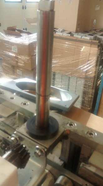
8 1.6.2 Machine Blocked: Working without the nuts causes that the cups hit the squeezer tray front or side. If the nuts are not well tight, these can be unscrewed leaving the cups free. When the cup is not well attached, it can get out of the shaft and hit the squeezer tray. This causes the machine blockage because the machine cannot finish all the squeezing cycle, so that after four seconds an error will be showed on the screen. This can cause internal mismatches in the machine, the cup shaft thread can be broken or the security ring that fixes it to the runner (I-471-E28). For check if the security ring is not damaged it shall be enough ensuring that the shaft has no possibility of inward movement to the machine. If you can make this movement, proceed to replace the security ring as stated in point 5 of these instructions. Internal mismatches will cause the machine remain blocked (Cup against the tray with the nut well tight) until the problems will be fixed. To fix this, follow point 5 of this manual. If the shaft thread is damaged and is not possible to tighten the nut, the shaft must be replaced by a new one following point 7 of this manual. The juicer gets blocked when squeezing, with the cups placed vertically in the lower position. This can be due to: - The balls of the squeezer tray are not completely screwed and the cups do not reach the end of the movement, preventing the switch from getting released. Check the balls position by sight and manually. - The squeezer tray balls do not match the cup size. Replace it with the correct ones. - The belt between the motor and the gear box is damaged and it slides once an effort is applied. You can normally hear the noise caused by the belt teeth getting released over the motor pulley. Replace it by opening the juicer as shown in section Counter sensor fail; by turning off the machine and then turn on, it works two cycles and it stops, the fail is that the counter sensor is not working properly


9 1.7 Thermal motor sensor The following picture will be shown on the screen: The message may differ depending on machine versions. In the UL version, will appear the message on the left and on other versions the right message will be shown. The motor has, in the stator coil winding, a thermal sensor that opens when the temperature reaches 105º C (221 F). When the temperature reaches this value the safety circuit is opened by the sensor, shows an error on the screen and leaves the machine out of service temporally. After a few minutes, once the motor temperature has dropped to acceptable value, the error disappears and the machine becomes operational again with no need of switch off from the mains. The reason can be: The fan placed in the main body doesn t work; hence it doesn t cool the motor down. If properly plugged in, check the tension arriving to connectors (between volts AC depending on versions). If tension arriving and fan still not working, replace the fan. - The squeezer tray balls are not fully screwed and the motor is then subject to a bigger effort. Check by sight and manually. - The squeezer tray balls don t match the cup size. - The cooling grill is being partially or completely blocked by any object. If the motor temperature is not clearly the reason of this error message, when the machine is cold or the error message doesn t disappear once the machine has cooled down. Check the following points: Disassemble the hopper track following point 2 of the instructions to get access to the connections box placed inner the machine. Afterwards check if there is continuity between pins (Ter-out / Ter-out y Ter-in / Ter-in) in the connections box. If the motor is cool and there is continuity, you must replace the electronic board


10 If there is no continuity in this plug, you must proceed to check continuity between both yellow wires of the motor plug. - If with the motor cold, there is no continuity, so proceed to replace the motor. - If there is continuity, the problem should be on the main wiring, so proceed to replace it. 1.8 Peel counter function The machine has an automatic system for warning when the peel collection bin is full. If you want to activate this function, please proceed as follows: - Turn off the machine's power switch. - With the machine off, press SELECT, and continue pressing while turning the power switch back on. Keep pressing for four seconds until you see the bins/chutes appear on the display panel alongside a three-digit figure. - Once this screen appears you need to enter the number of peels the machine needs to produce before the alarm goes off. By pressing SELECT intermittently, the number of peels will continue to increase. If, on the other hand, you press SELECT continuously for more than two seconds, the number will start reducing. - Once the number of peels has been selected, press STOP and that quantity will be held in the machine's memory. - Once the machine reaches the desired quantity it will stop and the two bins/chutes on the display panel will blink. To continue juicing, the peel deposit must be emptied and then the ON button pressed in order to reset the counter. The following picture will be shown on the screen: TO DEACTIVATE THE PEEL COUNTER. Repeat the previous operation and set the counter to zero


 and proceed to replace")


11 2.- REPLACE THE CONTROL BOARD - Unplug the machine from the power supply. - Follow points 3.1.1, 3.1.2, y for pull the basket out. - Unscrew 4 hopper track nuts and its joints, pull 4 caps out from the roof and its 4 screws. - Remove upwards the roof cover. Once all plugs have been disconnected loosen both brake nuts (marked in red) and proceed to replace the electronic board. Highly important: when the roof cover will be closed again, be sure that the weather strip is well placed and that all caps which covers the gap where the screws are placed, to ensure that the closure is hermetic
. 3.1.")


12 3.- DISASSEMBLE THE MACHINE (12 min) Unplug the machine from the main power supply Remove the external basket by turning it slightly Unscrew the nut which is on top of the fruit classifier and take it out by pulling out Remove the hopper basket along with the hopper sector by pulling out until it gets completely released from its axis


13 Remove 4 caps spotted in red and the screws below. When remove the 4 screws and the 4 rubber washers* you can disassemble the hopper track in one piece and then have easy access inner the machine. *It s highly recommended replace the rubber washers by new ones before assembling again to avoid future water leaks. When disassemble the hopper track, be careful not to lose the sponge which covers the hole where the wires pass through (these sponges avoid that insects get into the electronics)


 which fixes the front body to the chassis and")

14 3.2 Access inside the machine Lift the hopper track base slightly and proceed to unplug both connectors that came from the connections box, wires from the main switch, ground connection and fan wires Loosen 2-3mm. the 4 feet, unscrew four bolts (2 on the upper top and 2 on the bottom) which fixes the front body to the chassis and remove it carefully Unscrew both bolts on the bottom which fixes the back body to the chassis and remove it carefully


15 4.- Replace the power board For test the board measure the voltage on the voltage input (RED+ / RED-) and if there is no voltage 110v / 220v verify on the machine mains input and the 6A fuse. If there is 110v / 220v measure on the transformer output (OVDC / +12VDC) and there must be 12v. If there is no 12v of voltage proceed to replace the power board. For replace the board you can get access opening the watertight box shown on the picture below. ATTENTION: the wires on the left have 100v and 230v, that s why the mains must be disconnected before doing anything. Once opened, release the wires by pressing the orange strap of each connector, unscrew the screws which fixes the board and replace it. 5.- DISMANTLING OF MOTOR AND GEAR BOX IN Z Disassemble the connections box holder and the feeder ensemble by loosen the screws and nuts shown on pictures below

16 5.2. Unplug the capacitor and motor wires Remove the M8x20E bolt and washers that fix the rod


17 5.4. Lay the machine down on the tray shafts and remove the Allen screws M8x70 placed at the chassis bottom which fix the gear box to it Carefully remove the motor-gear box group Remove the belt Unscrew and remove the hexagonal head bolt M6x16, both washers T-9021 M6 and extract the lower pinion to extract the pushing plate


18 5.8. Remove the T-933-M6x25 mm hexagon head screws that fasten the motor Support to the gear box Disassemble the gear box 30L pulley, by taking first the M6x16 Allen screw off, that fastens the unblocking screw. Then remove the unblocking screw. (In the variant Z40-25C the pulley there will be a 48L pulley ref

/ Pulley 48L")


19 6.- ASSEMBLY OF GEAR BOX OF Z40 ASSEMBLY OF GEAR BOX SUBSET AND MOTOR WITH COPIER AND CONNECTING ROD 1. Grease the gear box shaft (210405), ratio 15:1. 2. Put the pulley 30L in (210408)/ Pulley 48L (210438) 3. Place the screw along with the welded washer (210428). 4. Put in the T-912-M6x16mm screw to block the unblocking screw. 5. Turn the gear box and check that both, screw and washer are balanced


20 6. Put in the motor base plate (210410), as shown in picture, leaving 2mm to the right edge of the gear box and as much as possible behind. Fasten the board to the gear box using 4 T-933-M6x25mm, 4 washers T-9021 M6 4 nuts T-934 M6. (In version Z40-25C there is no need of disassemble the shaft from the gearbox, so that both are one piece) 7. Place the 8x7x63 split pin in the gear box shaft. 8. Put the axis into the gear box in position and place it into the gear box. 9. Put the 5x5x18 split pin in the gear box shaft
 for 50Hz or (210406) for 60Hz and fasten it using 1 I-933-M5x12mm screw and 1 I-9021-M6 washer. 13.")

21 10. Put in the 12 teeth pinion chain. If it measures 25mm long you must put the ø14 x ø28 x 8 separator in. if it measures 33mm long, then put the pinion straight away. 11. Fasten with 1 T-933-M6x16mm screw and 2 T-9021-M6 washers. 12. Put the motor pulley in (210407) for 50Hz or (210406) for 60Hz and fasten it using 1 I-933-M5x12mm screw and 1 I-9021-M6 washer. 13. Assemble the motor over the silent-blocks with 4 T-934-M6 nuts and 4 T-9021-M6 washers. 14. Put the 187L 050 belt. Straighten and stretch. ASSEMBLY OF GEAR BOX SUBSET AND MOTOR IN CHASSIS 15. Grease the surface of the connecting rod contacting the pushing plate, place the whole motor group along with the gear box, put the connecting rod in vertical position and put it into the bolt. Close it using a ø 40 x ø 8 x 5 washer, trying to affix it as parallel as possible to the pushing plate. Then screw it using 1 T-933-M8x20 mm + 1 grower washer T-127-M8 screw along with 1 grower washer T127-M

 with 1 T-933-M6x16 mm screw and 1 T-934-M6 nut, fastening to the motor base. 19.")

22 16. Center the copier and pull backward the gear box. 17. Insert the 4 T-912-M8x70 screws that fasten the gear box to the chassis. ASSEMBLY OH THE SUBSET THAT TRIGGERS THE FEEDER 18. Place the pinion backing (210301) with 1 T-933-M6x16 mm screw and 1 T-934-M6 nut, fastening to the motor base. 19. Assemble pinion-feeder subset. 20. Affix the plate to the chassis using 2 T-933-M6x16 mm screws and 2 T-9021-M6 washers. 21. Put 2 T-9021-M6 washers in and 2 T-934-M6 nuts to affix the pinion support to the pinion backing. Insert the screws to screw them once the chain is placed. 22. Place the washer in the closing chassis axis. Introduce the cone-shape crown group and fasten using a safety ring

23
 until the connecting rod (Ref. 210411) (Part C) and the lower pinion keyway (Ref.")
 (Part E) with the keyway completely vertical. - Assemble the crown (Ref.")

24 IMPORTANT!! 23. To be able to adjust the mechanism, you must proceed as follows: - Turn the pulley (Ref ) until the connecting rod (Ref ) (Part C) and the lower pinion keyway (Ref ) (Part D) are completely vertical. - Place the upper pinion (Ref ) (Part E) with the keyway completely vertical. - Assemble the crown (Ref ) (Part A) with the tooth matching the ø 5mm hole into the coneshape pinion gap (Ref ) (Part B). Check that keyways of parts D and E are completely vertical. Place the E-471-E-20 ring on the hopper shaft to avoid the crown moving vertically. Important. The 3 marks line up every 7 cycles. - Assemble and stretch the chain


25 7.- PUSHING PLATE ADJUSTMENT (10 min) With the machine opened, take the stainless-steel slide cover off by removing the 6 screws that fasten it as shown in left picture. Make sure the pushing plate is in horizontal position and check the screws shown in right picture. In case they were loose, put the fixing stud in and tighten the screws. 8.- REPLACEMENT OF CUP SHAFT FIXING RING (5 min) To be able to access the I-471-E28 ring disassemble the front of the machine following the instructions in step #2. Once the front has been removed you will be able to access the cup shaft to put the ring with the help of some pliers as shown in the picture. The ring must fit properly into the axis slot. Check it is correctly fastened by trying to move the cup shaft towards the inside of the machine

26 9.- REPLACEMENT OF CUP SHAFT (10 min) For remove a cup shaft, you must remove the stainless-steel plate covering the slides as previously explained. Release the wedge spring and disengage wedges. With the connecting rod in vertical position, release the screw that fastens the axis to the ratchet. Put in the new axis having greased previously the surface inside the slide. Put the keyway between the axis and the ratchet and affix them using the screw and washer previously removed. Make sure the screw is properly tightened. Assemble the spring between the wedges. Turn the motor pulley to allow the connecting rod to go down and make sure the wedge engages the ratchet properly BEARING BALL REPLACEMENT (10 min) For replace the copier bearing proceed following steps showed on pictures below, since it is not necessary to disassemble the gear box for replace it. Firstly, loose the screw which holds the rod to the pin and then both countersunk Allen screws. (Spotted in red)


27 Once the screws were loosened, use a nylon hammer and a crowbar to pull out the pushing plate pin to let the rod free and then disassemble it. When removed the pin, the connecting rod will be free on the upper side of it, then turn the gear box clockwise until you have free access to get to the lower bearing and proceed to its substitution and reassemble it

 from the axis (210414).")

 in the blade slide (210412)")
28 Take off the axis with the bearing from the inner side of the machine. Remove the security ring I-471-E12 and take off the bearing (ROD. 6201ZZ) from the axis (210414). Place a new bearing and affix it with the safety ring. Insert it back in the slide from the inside of the machine towards the outside. Affix the ball bearing axis (210414) in the blade slide (210412) using 1 T-9021-M8 washer + 1 T-933-M8x20 mm screw, using fixing stud. To make sure it is tightened, use a 10-mm key on the edge of the ball bearing axis


29 11.- MACHINE SETUP LEVELS The maximum height the cup sliders must reach is given by the screw affixed to the chassis as shown in the picture below. The measure for make the default setting of the chassis closing must be around 40,4 to 41 mm. Once this measure has been set, with the connecting rod at its upper vertical position, check if there is minimum distance between the wedge and the ratchet of at least 1,5 mm to avoid a collision against each other and there will be enough space in between to ensure a safe fit

30 12.- Z40 ELECTRIC DIAGRAM
31 Z TECHNICAL INSTRUCTIONS 12.1 In the event of the need to change the machine wiring follow this color code when connect the magnetic sensors. - Squeezing tray sensor: couple of yellow wires - Self-service tap sensor: couple of black wires - Left bin sensor: couple of blue wires - Right bin sensor: couple of Brown wires - Counter sensor: couple of White wires The upper sensor wires (front cover, left side cover, right side cover and hopper basket) are wired on the interconnection of the hopper track FEEDER SYNCHRONISATION CHECKING If the machine feeds the fruits out of time, this can be owing to the feeder being out of synchronization, an improper use of both, lower and upper fruit classifiers for the fruit size being used, or any damage on the fruit classifiers. You can easily see if the synchronization is being properly or not only following next instructions: - Take the Allen key out of the machine bottom (right side) and introduce it on the hole placed on the right side of the machine. Then turn it clockwise
32 Z TECHNICAL INSTRUCTIONS By turning the key, achieve that the inner basket rotates until both; central rod of outer basket and one of the rods that fasten the feeder sectors are aligned on the same plane, as shown in the following picture on the right side. When basket is like show in left picture above, cups must remain vertical and facing up as shown in picture below. If this is not the case, disassemble the machine following the instructions in step 2 and adjust the feeder operation, following the instructions in section 4, 3. If cups were properly placed, check condition and position of fruit classifiers


33 12.- MACHINE CLOSING (18 min) 1. Assemble the body subset again. Placing the tab inside the front. Connect ground wires, power wires to the main switch and the fan wires. Fasten the body by using two Hexagonal head screws DIN-933- M6x10 mm. 2. Assemble the whole hopper track considering that the plugs to the electronic box are properly plugged. 3. Assemble the Hopper track top and all the sides (having special care not to smash the wires from the box). Then screw the four cross countersunk head screws with the rubber washer and then cover with the grey cups
34 4. Assemble the complete internal basket (210330). The internal classifier (210322) will fit in the hole depending on the fruit size you are planning to use. Then put the appropriate external classifier (210319) for the fruit size. 5. In case the legs had previously been removed, assemble the legs to the chassis. The front legs must have the support washers (210213) and will be adjusted to a height of 140mm, whereas the rear ones do not bear any washer and will be adjusted to 142mm. 6. Assemble the basket (210352). 7. Assemble all the squeezing system and coverings. 8. Plug the machine using the power cable and test it non-stop for 30 minutes. In addition to that, also verify the parts on boxes B or D accordingly
VECTRIX VX-2 SERVICE MANUAL. Version 1.0/May 2011 VECTRIX, LLC
 www.vectrix.com CONTENTS SECTION A: Tools 1 Tools Needed SECTION B: Mechanical Parts 1 Front Fairing 2 Front Console Cover 3 Speedometer Cover 4 Front Vertical Panel Cover-Lower 5 Front Vertical Panel
Installation Manual TWM Performance Short Shifter Cobalt SS/SC, SS/TC, HHR SS, Ion Redline and Saab 9-3
 Page 1 Installation Manual TWM Performance Short Shifter Cobalt SS/SC, SS/TC, HHR SS, Ion Redline and Saab 9-3 Please Note: It is preferable to park on a flat surface, as you will have to engage and disengage
Upgrade v3 to v3.2. SeeMeCNC Guides. Upgrade v3 to v3.2. Rostock Max v3 Uprgade to v3.2. Written By: SeeMeCNC seemecnc.dozuki.
 SeeMeCNC Guides Upgrade v3 to v3.2 Rostock Max v3 Uprgade to v3.2 Written By: SeeMeCNC 2018 seemecnc.dozuki.com/ Page 1 of 34 INTRODUCTION This guide is intended to Upgrade a Rostock Max v3 to a Rostock
Transmission Overhaul Procedures-Bench Service
 How to Assemble the Lower Reverse Idler Gear Assembly Special Instructions In 1996 Eaton changed the reverse idler system design. In the nut design, the reverse idler bearing was lubricated through a hole
MICROGUARD 500 EXTENSION REEL TRAINING MANUAL. Greer Company. Greer Company Crane Systems 1 OF18
 MICROGUARD 500 EXTENSION REEL TRAINING MANUAL 1 OF18 TABLE OF CONTENTS MICROGUARD 500 SERIES EXTENSION REEL TRAINING MANUAL EXTENSION REEL OVERVIEW...3 REEL-OFF CABLE LAYERING...3 CHECKING THE REEL-OFF
SX1000 Service Manual SALES: CUSTOMER SERVICE:
 SX1000 Service Manual SALES: 800-278-3933 CUSTOMER SERVICE: 800-745-1373 Revision: August 1999 Table of Contents Section Page I. Overview 2 II. Troubleshooting Tables 3 III. Maintenance Procedures Procedure
CALIFORNIA TRIMMER MOWER MAINTENANCE MANUAL
 CALIFORNIA TRIMMER MOWER MAINTENANCE MANUAL 2 Table of Contents Section 1: General Information Page Handle Assembly Instructions 4 Maintenance All Models 6 Oil Change Procedures All Models 9 Height Adjustment
SIGNETMARINE. Livewell Bait Pump Alarm. No Dead Bait.
 B A I T WAT C H SIGNETMARINE Livewell Bait Pump Alarm No Dead Bait. The SIGNETMARINE BaitWatch System alerts you to a livewell pump problem before your fishing trip turns into one. The loud alarm and dual-color
Troubleshooting Guide: 255 LED Light
 Troubleshooting Guide: 255 LED Light Note Use only factory replacement lights (refer to parts list for order number). Caution Carefully handle parts near membranes and wire harnesses. Allow the light to
ZUMMOVENDING web: LIST OF COMPONENTS
 LIST OF COMPONENTS ZUMMOVENDING web: www.zummo.ru Code Description 0502004 BLADE SLIDE COVER 0502005 CUP SLIDE COVER 0503001 FEED PADDLE 0503003 FEEDER LEVER SHAFT 0503004A 0503005A FEEDER LEVER FEED PADDLE
Maintenance Information
 Form 16575334 Edition 1 April 2005 Electric Screwdrivers EL, EP and ET 34V DC Series Maintenance Information Save These Instructions WARNING Maintenance procedures have the potential for severe shock hazard
Service Information Chevrolet Camaro 3.6L LFX Engine. Camshaft Position Actuator Replacement - Bank 1. Document ID:
 Service Information 2014 Chevrolet Camaro 3.6L LFX Engine Camshaft Position Actuator Replacement - Bank 1 Document ID: 2900815 Special Tools Removal Procedure EN49982-1 Timing Chain Retainer EN49982-2
REMOVAL & INSTALLATION
 REMOVAL & INSTALLATION Removal 1. Center steering wheel. Disconnect negative battery cable. Remove steering coupling shield (if equipped). Disconnect steering shaft at flexible coupling or pot joint. Note
INSTALLATION INSTRUCTIONS FOR DSP9600/9100 WHEEL BALANCER
 Form 5063T, 06-05 Supersedes Form 5063T, 02-04 INSTALLATION INSTRUCTIONS FOR DSP9600/9100 WHEEL BALANCER This document provides the information needed to install the DSP9600/9100 Wheel Balancer. NOTE:
PROBLEM SOLVING GUIDE ELMECO SLUSH MACHINE MODEL FCM
 A01 INSTRUCTIONS ON HOW TO READ REFERENCES...2 A10 FEATURES AND TECHNICAL SPECIFICATIONS...3 A15 RECOMMENDED PREVENTIVE MAINTENANCE SPARE PARTS KIT...3 A20 IMPORTANT INFORMATION ON FUNCTIONALITY OF THE
PRODUCT INFORMATION BULLETIN #3365 DIGITAL MOTOR CONTROL PLATTER SYSTEMS For Serial Number and After
 PRODUCT INFORMATION BULLETIN #3365 DIGITAL MOTOR CONTROL PLATTER SYSTEMS For Serial Number 28640996 and After Record Platter System Identification Numbers Here: Model # Serial # Table of Contents Program
SIDI Camshaft Position Actuator Replacement
 BLOCK AND WEDGE TIMING CHAIN RETAINER USER GUIDE SIDI Camshaft Position Actuator Replacement Removal Procedure 1. Remove the camshaft cover. 2. Remove the camshaft position actuator solenoid valve solenoid
Auto Sentry-eXP Maintenance. Revised 12/21/07
 Auto Sentry-eXP Maintenance Revised 12/21/07 Maintenance Procedures for Auto Sentry exp Bill Dispenser Credit Card Reader Bill Acceptor Bill Dispenser Maintenance Bill Dispenser Problem / Cause Bill Dispenser
SERVICE MANUAL (DOMESTIC & INTERNATIONAL)
") SERVICE MANUAL (DOMESTIC & INTERNATIONAL) DUAL TECHNOLOGY FINISHER MODEL 1960 & 1980 SERIES Lincoln Foodservice Products, LLC 1111 North Hadley Road Fort Wayne, Indiana 46804 United States of America Telephone:
SERVICE MANUAL (DOMESTIC & INTERNATIONAL) DUAL TECHNOLOGY FINISHER MODEL 1960 & 1980 SERIES Lincoln Foodservice Products, LLC 1111 North Hadley Road Fort Wayne, Indiana 46804 United States of America Telephone:
Section 5: Parts Replacement
 Section 5: Parts Replacement Should the STAR TRAC 4500 Treadmill experience a problem requiring replacement of a specific part, the following procedures will help and instruct in the replacement of major
Prusa i3 Printer Assembly Guide
 Prusa i3 Printer Assembly Guide Special thanks to Carlos Sanchez and Miguel Sanchez for the graphics. All graphics captured from their great animation: http://www.carlos-sanchez.com/ Prusa3/ For copyright
ISO1000R Service Manual SALES: CUSTOMER SERVICE:
 ISO1000R Service Manual SALES: 800-278-3933 CUSTOMER SERVICE: 800-745-1373 Revision: August 1999 Table of Contents Section Page I. Overview 2 II. Troubleshooting Tables 3 III. Maintenance Procedures Procedure
JBI Docupunch P33 Automatic Punch
 JBI Docupunch P33 Automatic Punch Instruction Manual Provided By http://www.mybinding.com http://www.mybindingblog.com TABLE OF CONTENTS SECTION I: INSTALLATION & TESTING: 1) Uncrating, Inspection & removal
TECHNICAL INFORMATION
 TECHNICAL INFORMATION Model No. Description GA5020C/GA6020C, GA5021C/GA6021C Angle Grinders 125mm (5") /150mm (6") L PRODUCT P 1/10 CONCEPT AND MAIN APPLICATIONS These four models have been developed as
Installation Instructions COMPETITION/PLUS SHIFTER Ford Mustang MT82 6-Speed Manual Transmission Catalog#
 Installation Instructions COMPETITION/PLUS SHIFTER 2015-2017 Ford Mustang MT82 6-Speed Manual Transmission Catalog# 3916037 Rev. 00 WORK SAFELY! For maximum safety, perform this installation on a clean,
ROUSH Active IO Exhaust. Installation Instructions P/N: (R LITE) Fastback GT Convertible GT V8
 Fastback GT Convertible GT V8") Installation Instructions P/N: 422128 (R1318-5231LITE) Fastback GT Convertible GT V8 39555 Schoolcraft Rd, Plymouth MI, 48170 800.59.ROUSH ROUSH Active IO Exhaust Installation Instructions P/N: 422128
Installation Instructions P/N: 422128 (R1318-5231LITE) Fastback GT Convertible GT V8 39555 Schoolcraft Rd, Plymouth MI, 48170 800.59.ROUSH ROUSH Active IO Exhaust Installation Instructions P/N: 422128
Sure-Feed Engineering Inc. SE-900-EI. Operation & Parts Manual
 . SE-900-EI Operation & Parts Manual SE 900 EI OWNERS MANUAL Table of Contents 1. Installation guide 2. Set-up instructions 3. Operation instructions 4. Cleaning 5. Troubleshooting 6. Parts manual 7. Electrical
#TL T EA888 GEN 3 FUELING SYSTEM/ INSTALLATION INSTRUCTIONS
 #TL100069 2.0T EA888 GEN 3 FUELING SYSTEM/ INSTALLATION INSTRUCTIONS Notes: These instructions were written for a North American specification MkVII GTI. Other models, like the Golf R, are similar. When
DrVanos.com Stage II Installation Instructions. Tool rental is available with the purchase of a vanos kit *See website for more info*
 DrVanos.com Stage II Installation Instructions Special Tools Needed: Camshaft locking tool TDC Crank pin Sprocket turning tool Tool rental is available with the purchase of a vanos kit *See website for
CONTENTS. Product Features and Specifications Installation Requirement Installation Exploded View Operation Instruction...
 1 CONTENTS Product Features and Specifications... 3 Installation Requirement... 5 Installation... 6 Exploded View... 20 Test... 22 Operation Instruction... 25 Maintenance... 26 Trouble Shooting... 27 Parts
M Damper Mount Linkage Kit Installation. Item Description Quantity Item Description Quantity Nuts 2
 FANs 268.1, 1628.3 Installation Bulletin M9000-150 Issue Date 0796 M9000-150 Damper Mount Linkage Kit Installation 21 18 19 20 2 22 17 2 4 3 2 15.5 393.7 1 17 16 15 11 13 12 8 9 10 2 5 Note: Damper mount
FRONT SEAT TRACK MOTOR. Removal
 1 of 19 FRONT SEAT TRACK MOTOR Removal WARNING: - Always wear safety glasses when repairing a supplemental restraint system (SRS) vehicle and when handling an air bag module. This will reduce the risk
METROLOGIC INSTRUMENTS, INC. MX001 Industrial Control Interface Installation and User s Guide
 METROLOGIC INSTRUMENTS, INC. MX001 Industrial Control Interface Installation and User s Guide Copyright 2007 by Metrologic Instruments, Inc. All rights reserved. No part of this work may be reproduced,
The POWER. In PRESENTATION PRODUCTS. Instruction Book for COSMOPOLITAN ELECTROL For Sizes Up To 9'x12' DA-LITE SCREEN COMPANY, INC.
 The POWER In PRESENTATION PRODUCTS Instruction Book for COSMOPOLITAN ELECTROL For Sizes Up To 9'x12' DA-LITE SCREEN COMPANY, INC. 3100 North Detroit Street Post Office Box 137 Warsaw, Indiana 46581-0137
Safe-T-element Installation Instructions
 Safe-T-element Installation Instructions For: PTI STEZA (2x2 Burner Configuration) & PTI STEZB (3x1 Burner Configuration) Revision K (May. 3 2012) TABLE OF CONTENTS 1. PREPARATION... 3 1.1 General Safety
Front Drive System - Big Block Chevy Installation Instructions Big Block Chevy with AC & with PS
 Front Drive System - Big Block Chevy Installation Instructions Big Block Chevy with AC & with PS All American Billet Store (800) 764-0926 www.allamericanbilletstore.com Items needed for install Jack Jack
SE-1200-MP ECO - SERIES
 Inc. SE-1200-MP ECO - SERIES Operation & Parts Manual SE 1200 MP ECO -SERIES OWNERS MANUAL Table of Contents 1. Installation guide 2. Set-up instructions 3. Operation instructions 4. Cleaning 5. Troubleshooting
Service Manual Gulf Stream Electronic Full Wall Slide Systems
 Service Manual Gulf Stream Electronic Full Wall Slide Systems CONTENTS Page Before you operate the slide system 2 Operating Instructions 3 Preventive maintenance 3 Manually overriding your slide system
1989 Jeep Cherokee. STEERING COLUMN' '1989 STEERING Jeep Steering Columns STEERING COLUMN STEERING Jeep Steering Columns
 STEERING COLUMN 1989 STEERING Jeep Steering Columns DESCRIPTION All models use collapsible steering columns. All columns have integral ignition switch and locking device. Optional tilt wheel is available
Note: Replace the washer and the spacer above the turgo or the shaft adapter with the spacer above the washer as shown in the following pictures.
 BEARINGS, SERVICE & ASSEMBLY IMPORTANT Bearing maintenance is important. You should replace bearings ONCE PER YEAR or as soon as you notice any looseness from wear. If they are too loose, severe damage
Installation Instructions LamboStyleDoors (The instruction are to be used as a reference. Please repeat for both doors)
") Installation Instructions LamboStyleDoors (The instruction are to be used as a reference. Please repeat for both doors) Mercedes C-Class Sport coupé type W203 Part number 500 25 009 Pre installation check
Installation Instructions LamboStyleDoors (The instruction are to be used as a reference. Please repeat for both doors) Mercedes C-Class Sport coupé type W203 Part number 500 25 009 Pre installation check
T-Dolly Troubleshooting Guide
 T-Dolly Troubleshooting Guide Complete following items before beginning troubleshooting 1. Place wheel chocks and jack stands in place per the BLOCKING DIAGRAM decal. Located on the underside of the pump
XR Conveyor Maintenance Guide
 XR Conveyor Maintenance Guide EN-0035 Rev. A XR Conveyor Maintenance Guide www.qdraw.com Table of Contents 05/20/2009 Overview Page 3 XR Conveyor Assembly Page 4 General Information Exploded View of an
V6 Spring Belt Tensioner
 Dodgerunner s V6 Spring Belt Tensioner Installation Guide Dodgerunner 2007 The bracket consists of two pieces of 1/8" steel bolted together. The main piece is flat plate with welded-on alternator mounting
Shelby GT500 Front Fascia Conversion Kit (05-09 All) Item # Installation Time: 1 Day. Required tools:
 Item # Installation Time: 1 Day. Required tools:") Shelby GT500 Front Fascia Conversion Kit (05-09 All) Item #53611 Installation Time: 1 Day Required tools: Phillips Screw driver 10mm Socket + Ratchet/Wrench 8mm Socket + Ratchet/Wrench 5mm Socket + Ratchet/Wrench
Shelby GT500 Front Fascia Conversion Kit (05-09 All) Item #53611 Installation Time: 1 Day Required tools: Phillips Screw driver 10mm Socket + Ratchet/Wrench 8mm Socket + Ratchet/Wrench 5mm Socket + Ratchet/Wrench
DIAGNOSTIC TROUBLESHOOTING INDEX
 DIAGNOSTIC TROUBLESHOOTING INDEX Curtis Industries, LLC. 111 Higgins Street Worcester, MA 01606 Telephone: (508) 853-2200 Fax: (800) 876-9104 www.snoproplows.com TROUBLESHOOTING INDEX - BY PROBLEM Section
ELECTRICAL. Contents - Wiring Diagrams
 Contents - Wiring Diagrams T-Bar (Floating Deck - Hydro)............................................ 8-16 T-Bar (Fixed Deck - Gear)............................................... 8-17 T-Bar (Fixed Deck
Measurement and Analysis of the Operation of a Single-Phase Induction Motor
 Measurement and Analysis of the Operation of a Single-Phase Induction Motor In class I have shown you the carcass of a four-pole, single phase, ¼ HP motor in varying stages of disassembly. In this lab,
POWER STEERING PUMP REBUILDING SPK101 Read instructions completely before removal & disassembly
 POWER STEERING PUMP REBUILDING SPK101 Read instructions completely before removal & disassembly DISASSEMBLY: 1. Remove pump from car and allow to drain. 2. Remove pulley from front of pump. This requires
Maintenance Information
 45530136 Edition 1 July 2008 Electric Screwdrivers EL 24V DC Series Maintenance Information Save These Instructions WARNING Always wear eye protection when operating or performing maintenance on this tool.
1. Main parts and function introduction
 1. Main parts and function introduction 1.1 hopper : Using as bracket for bills loading, bills run Hopper smooth when the gap of hopper and feeding roller is proper. The machine operates while the feeding
LPE C5 Battery Relocation Kit
 LPE C5 Battery Relocation Kit The LPE C5 Corvette battery relocation kit improves vehicle weight distribution by moving weight to the rear of the vehicle. The improved weight distribution increases traction
Instructions for MB832 Manual Barrier Ver0614
 Instructions for MB832 Manual Barrier Ver0614 Read all the instructions before starting It is recommended that Locktite Blue brand thread sealant be used for all arm and pivot bolts as added protection
C15C C15C. Page 1 of 20
 2 x Lid Front Hinge 1135 8 x M8 Bolt 8 x M8 Washer (3mm Thick) 4 x M6 Large washers 4 x M6 Spring washers 4 x M6 x 40mm Bolts 6 x M6 20mm Bolts 6 x M6 Washers 20 x Screws 2 x Lid mount gas strut bracket
Conflicts: Vehicles without a sunroof Vehicles with a single sunroof
 Toyota Sienna (Dual Sunroof) 2011-10.2 Overhead Video Part Number: 00016-00110 00016-00110-17 Fit Kit 00016-00120 00016-00120-17 Fit Kit Accessory Code: ED5 Conflicts: Vehicles without a sunroof Vehicles
Depress each tab as you pull the bezel off. The bezels are tight. L.H. shown.
 2013-2014 Ford Mustang V6 & Boss 302 Lower Valance Fog Light Kit Parts List: Quantity: Tool List: Fog light & bulb with bracket 2 Flat head & Phillips screwdriver Black bezels 2 Ratchet & Socket set OR
PARTS & SERVICE MANUAL
 PARTS & SERVICE MANUAL Impinger Low Profile Advantage Digital Series (Electric) International Models MODELS: Please note that the model numbering system changed March 2007. The chart below shows the old
SERVICE MANUAL TDR - ROTISSERIE OVEN MODELS TDW - WARMER MODELS
 SERVICE MANUAL TDR - ROTISSERIE OVEN MODELS TDW - WARMER MODELS MODELS TDR 5 M TDR 7 M TDW 5 M TDW 7 M Model TDR 5 M Model TDR 7 M - NOTICE - This manual is prepared for the use of trained Service Technicians
All of the control valves that we install the Mk. 16IQ positioner on are factory calibrated for proper operation prior to shipment.
 1 Troubleshooting The first thing you need is information... Try to find out what is wrong and why. Getting a serial number (found on the valve tag (see above)) and application parameters are always helpful
Maintenance Information
 Form 04584058 Edition 1 November 2004 Air Impactool 2141P and 2141PSP Maintenance Information Save These Instructions Disassembly General Instructions 1. Do not disassemble the tool any further than necessary
6204 Series Low-Volume Inserter
 204 Series Low-Volume Inserter /2012 MAINTENANCE MANUAL Mechanical description Mechanical description...51 General...52 Covers and plates...52 Electrical components...57 Feeder modules...0 Document feed...4
Heavy duty slurry pumps
 USERS MANUAL Heavy duty slurry pumps TOYO PUMPS EUROPE Edition 27.07.2007 SAFETY INSTRUCTIONS TOYO PUMPS EUROPE Users manual for Toyo pumps type «DP..-6 30~40HP» This users manual will help you to maintain
3M Overhaul Service Kit
 SERVICE INSTRUCTIONS FOR 3M 12,000 RPM 3 in. (77 mm) RANDOM ORBITAL SANDERS 3M Overhaul Service Kit The part number 20346, 3M Overhaul Service Kit, contains all the replacement parts that naturally wear
Specific information for calibre 3603
 Fig. 1.0 1.0 Assembling of date indication 1. Stem in position 3 : Turn anti-clockwise the driving wheel for date unlocking yoke (reference 33029) until the finger of this wheel is aligned with the pin,
Audi A8 ( ) MMI swivelling unit repair manual
 MMI swivelling unit repair manual") Audi A8 (2003-2007) MMI swivelling unit repair manual Tools which you will need: two pcs screwdriver (any kind, for vent removing ) (you can cover the metal part with any tape to prevent making scratches
Audi A8 (2003-2007) MMI swivelling unit repair manual Tools which you will need: two pcs screwdriver (any kind, for vent removing ) (you can cover the metal part with any tape to prevent making scratches
INSTALLATION INSTRUCTIONS
 INSTALLATION INSTRUCTIONS FUEL SURGE TANK INSTALL KIT Honda S2000 Document# 19-0063 Support: info@radiumauto.com WARNING: DO NOT SMOKE WHILE WORKING ON FUEL SYSTEMS. KEEP SPARKS AND OPEN FLAMES AWAY FROM
This LED flashtube kit covers models 400, 404, 500, 504, 600, 680 & 506.
 L.E.D. INSTRUCTIONS I D T S O T U B I R M O C R Y N A P Kit contains: This LED flashtube kit covers models 400, 404, 500, 504, 600, 680 & 506. For the power supply: 1-LED power supply circuit board, 2
OPEN/CLOSE SERVICE ELECTRIC ACTUATORS OPERATION AND MAINTENANCE MANUAL COMMERCIAL AND INDUSTRIAL VALVES AND AUTOMATION
 SERIES 1000-X OPEN/CLOSE SERVICE ELECTRIC ACTUATORS OPERATION AND MAINTENANCE MANUAL COMMERCIAL AND INDUSTRIAL VALVES AND AUTOMATION Publication S1000X-110 VER0215-1 For information on this product and
INSTALLATION & OWNER S MANUAL
 Rev. E p. of 3 INSTALLATION & OWNER S MANUAL V446 Front Cab Kit and V446 Rear Cab Kit for RTV 40 INSTALLATION & OWNER S MANUAL The contents of this envelope are the property of the owner. Be sure to leave
PARTS & SERVICE Manual for PANORAMA ROTISSERIE Model SP-7
 PARTS & SERVICE Manual for PANORAMA ROTISSERIE Model SP-7 THIS MANUAL SHOULD BE RETAINED FOR FUTURE USE SP7serv 12-22-08 WARRANTY The SP-7 carries a 1 year warranty on parts and labor from date of unit
Copper Sleeve, Unit Injector, Replacement
 Volvo Trucks North America Greensboro, NC USA This service bulletin replaces SB 237-46, Copper Sleeve, Unit Injector, Replacement dated 6.2007, publication no. PV776-20177417. DService Bulletin Trucks
Maintenance Information
 16572679 Edition 2 May 2014 Air Drill QP Series Maintenance Information Save These Instructions Product Safety Information WARNING Failure to observe the following warnings, and to avoid these potentially
Operation and Maintenance Instructions
 Operation and Maintenance Instructions One Research Drive Stratford, CT 06615 (203) 375-0063 www.sonicmixing.com 1 Installation and Start-up Do not perform following adjustments without disconnecting power
MAINTENANCE ROAD 2013 WHEELS TECHNICAL MANUAL
 2013 WHEELS TECHNICAL MANUAL ROAD CYCLOCROSS PISTA GROUPSET TYPE OPERATION REVISION DESCRIPTION ROAD GROUPSETS CONE / CUP MOVEMENT 002 1/2011 SERVICING FRONT HUB ASSEMBLY PRODUCTS ON WHICH THE PROCEDURE
PF3100 TROUBLESHOOTING SOLUTIONS TO COMMON PROBLEMS. v1.1 Revised Nov 29, 2016
 PF3100 TROUBLESHOOTING SOLUTIONS TO COMMON PROBLEMS v1.1 Revised Table of Contents 1 Common Alarms and Warnings... 1 2 Common Issues... 6 2.1 Communication problems... 6 2.1.1 Controller communication
Installation Instructions LamboStyleDoors (The instruction are to be used as a reference. Please repeat for both doors)
") Installation Instructions LamboStyleDoors (The instruction are to be used as a reference. Please repeat for both doors) Hyundai enesis Coupé type BK38 Part number 500 66 002 Pre installation check list:
Installation Instructions LamboStyleDoors (The instruction are to be used as a reference. Please repeat for both doors) Hyundai enesis Coupé type BK38 Part number 500 66 002 Pre installation check list:
Installation Manual TWM Performance 2010 Mazda 3 short shifter 5 and 6 speed non-mazdaspeed
 Installation Manual TWM Performance 2010 Mazda 3 short shifter 5 and 6 speed non-mazdaspeed Begin the installation by parking on a flat surface, as you will have to engage and disengage the hand brake
Last Revision: 30JN THRU 1979 C3 CORVETTE STANDARD (NON-ADJUSTABLE) STEERING COLUMN DISASSEMBLY & REPAIR INSTRUCTIONS PAPER #2
 STEERING COLUMN DISASSEMBLY & REPAIR INSTRUCTIONS PAPER #2") Last Revision: 30JN2007 1969 THRU 1979 C3 CORVETTE STANDARD (NON-ADJUSTABLE) STEERING COLUMN DISASSEMBLY & REPAIR INSTRUCTIONS PAPER #2 Disassembly and Repair Instructions Addressed in this Paper Degree
Last Revision: 30JN2007 1969 THRU 1979 C3 CORVETTE STANDARD (NON-ADJUSTABLE) STEERING COLUMN DISASSEMBLY & REPAIR INSTRUCTIONS PAPER #2 Disassembly and Repair Instructions Addressed in this Paper Degree
Kodak 750H Carousel Projector Repair
 Kodak 750H Carousel Projector Repair An AT YOUR OWN RISK PROJECT by Klaus Wolter, Rev B, 3-26-2016 Here I documen the repair of my 750H carousel. A common problem with this projector, and all of the projectors
KEYSTONE FIGURE 79 PNEUMATIC ACTUATOR OPERATING AND MAINTENANCE INSTRUCTIONS
 Operating and Maintenance Instructions for: Figure 79 Pneumatic Actuators (U/E options) Double Acting Actuator 4. If pipelines are hydraulically tested, then the lines should be blown down with high pressure
OIL COOLER KIT INSTALLATION INSTRUCTIONS PART NUMBER D E92 335i/xi (N55 engine) with M-Technic bumper and without stock oil cooler
 with M-Technic bumper and without stock oil cooler") OIL COOLER KIT INSTALLATION INSTRUCTIONS PART NUMBER D570-0925 APPLICATION 2011-12 E92 335i/xi (N55 engine) with M-Technic bumper and without stock oil cooler Congratulations for being selective enough
OIL COOLER KIT INSTALLATION INSTRUCTIONS PART NUMBER D570-0925 APPLICATION 2011-12 E92 335i/xi (N55 engine) with M-Technic bumper and without stock oil cooler Congratulations for being selective enough
ROTARY MOWER SERVICING MANUAL
 ROTARY MOWER SERVICING MANUAL 567441.A.4 WWW.MASPORT.COM Contents CONTROLS 3 Engine Controls 3 Throttle Control Adjustment 3 Throttle Control Replacement 3 OPC Control Adjustment 3 Propulsion Controls
2020 Dual Tabber Operation Manual
 2020 Dual Tabber Operation Manual Revision 1.2 10 Clipper Road 10/24/2006 West Conshohocken, PA 19428-2721 Tel : 800-523-0320 / 610-825-6205 Fax: 610-825-1397 www.secap.com Index SECTION 1 Introduction
160S Rewind Option Kit Installation Instructions
 Installation Instructions GENERAL This kit includes the parts and documentation necessary to install the Media Rewind Option into the Zebra 160S printer. Read these instructions thoroughly before attempting
INSTALLATION & OWNER S MANUAL
 Rev. B, p. 1 of 25 INSTALLATION & OWNER S MANUAL POLARIS RANGER RCS (for models XP or HD) (for model years 2009-) cab without doors kit (p/n 1POLRCWD) cab with doors kit (p/n 1POLRC) doors only kit (p/n
HURST COMP/PLUS SHIFTER 2015 Ford Mustang (Getrag MT82 six-speed manual transmission) Catalog # by Hurst Performance
 Catalog # by Hurst Performance") FORM 159 0205 07/15 HURST COMP/PLUS SHIFTER 2015 Ford Mustang (Getrag MT82 six-speed manual transmission) Catalog #391 0205 2015 by Hurst Performance Thank you for purchasing the Hurst Comp/Plus Shifter.
FORM 159 0205 07/15 HURST COMP/PLUS SHIFTER 2015 Ford Mustang (Getrag MT82 six-speed manual transmission) Catalog #391 0205 2015 by Hurst Performance Thank you for purchasing the Hurst Comp/Plus Shifter.
Table of Contents. Timer Identification Timer ID BLU-U Features: 1K 6K BLU-U Features 1K 6K
 DUSA Pharmaceuticals, Inc. Table of Contents Go to Chart # Timer Identification Timer ID BLU-U Features: 1K 6K BLU-U Features 1K 6K BLU-U Features: 10K BLU-U Features 10K BLU-U Symptom Fans Running, Timer
Arch HTH Water Chemicals Commercial Equipment Trouble Shooting Guide
 Arch HTH Water Chemicals Commercial Equipment Trouble Shooting Guide 8/28/00 TROUBLESHOOTER S GUIDE PROBLEM CAUSE SOLUTION Insufficient water flow to chlorinator Check water flow through Flow Controller
TABLE OF CONTENTS. Ram Assembly
 TABLE OF CONTENTS DUC Cover------------------------------------------------------------------------------------ 00 Table of Contents----------------------------------------------------------------------------
Operating and Maintenance Instructions for: Figure 79 Pneumatic Actuators (U/E options)
") for: Figure 79 Pneumatic Actuators (U/E options) Introduction The Keystone Figure 79 Pneumatic Actuator range is available in three mounting options, as follows:- 79U - Keystone Mounting Standard 79E -
for: Figure 79 Pneumatic Actuators (U/E options) Introduction The Keystone Figure 79 Pneumatic Actuator range is available in three mounting options, as follows:- 79U - Keystone Mounting Standard 79E -
Installation Manual DELT. Platform stairlift. Web: Tel: Mobile:
 Installation Manual DELT Platform stairlift Web: www.lehner-lifttechnik.at Tel: +4372783514 Email: office@lehnerlifttechnik.at Mobile: +436641612980 Table of content OBSERVE THE FOLLOWING POINTS BEFORE
Installation Manual TWM Performance Short Shift Kit Estimated Installation Time: Tools required:
 Page 1 Installation Manual TWM Performance Short Shift Kit 1993-2001 Nissan Altima 1991-2001 Infiniti G20 1991-2001 Nissan Sentra- 200SX 1991-1993 Nissan NX 1986-1989 Nissan Stanza 1995-2001 Nissan Maxima
Sub Section Title Page No.
 Sub Section Title Page No. 1 Introduction 3 2 Routine Maintenance 3 3 Disassembly 4 3.1 Disassembly of Double Crank Design 4 3.2 Disassembly of Scotch Yoke Design 5 3.3 Disassembly of Actuator Cylinder
ALL AMERICAN BILLET. Front Drive System - Small Block Ford Installation Instructions
 ALL AMERICAN BILLET Front Drive System - Small Block Ford Installation Instructions Small Block Ford with AC & PS All American Billet Store (800) 764-0926 www.allamericanbilletstore.com Items needed for
SERVICE MANUAL. Chairman 2k/2s
 SERVICE MANUAL Chairman 2k/2s US How to contact Permobil Permobil Inc. USA 6961 Eastgate Blvd. Lebanon, TN 37090 USA Phone: 800-736-0925 Fax: 800-231-3256 Email: info@permobilusa.com Head Office of the
SERVICE MANUAL (INTERNATIONAL)
") SERVICE MANUAL (INTERNATIONAL) IMPINGER CONVEYOR OVENS MODEL 1421-000-E, 1454, 1455 WITH PUSH BUTTON CONTROLS Lincoln Foodservice Products, LLC 1111 North Hadley Road Fort Wayne, Indiana 46804 United States
SERVICE MANUAL (INTERNATIONAL) IMPINGER CONVEYOR OVENS MODEL 1421-000-E, 1454, 1455 WITH PUSH BUTTON CONTROLS Lincoln Foodservice Products, LLC 1111 North Hadley Road Fort Wayne, Indiana 46804 United States
The machine has been overhauled in 2016
 ZENO hammer mill Type ZHM 1000/2000 x 700 Constructed in 2002 Drive power 200 kw The machine has been overhauled in 2016 Technical specifications Manufacturer ZENO Zerkleinerungsmaschinenbau Norken GmbH,
Auto-Level Troubleshooting (Old Platform) Electronic Control- Prior to 2009, Pressure Switch Control panel #s 2057, 2058, 2795, 2795B
 Electronic Control- Prior to 2009, Pressure Switch Control panel #s 2057, 2058, 2795, 2795B") Auto-Level Troubleshooting (Old Platform) Electronic Control- Prior to 2009, Pressure Switch Control panel #s 2057, 2058, 2795, 2795B This guide addresses the troubleshooting of electronic controls used
Auto-Level Troubleshooting (Old Platform) Electronic Control- Prior to 2009, Pressure Switch Control panel #s 2057, 2058, 2795, 2795B This guide addresses the troubleshooting of electronic controls used
Printed from MediaCat
 Illustration A Crankcase Illustration A Crankcase Ref.Nr. Item code Quantity Description 1 1106 020 2506 1 Crankcase (2) 2-11 2 0000 988 5217 1 Connector (2) 3 0000 988 5200 2 Connector (2) 4 1106 641
Fig.01 Fig.02 Fig.03. Disassembly & Reassembly Instructions SBV-HP - Page 3
 M12A14 WITH FLOATING BACKSEAT 3 Fig.01 Fig.02 Fig.03 Disassembly & Reassembly Instructions SBV-HP - Page 3 M12A14 WITH FLOATING BACKSEAT 3 1. Caution, before any attempt is made to disassemble, verify