MAINTENANCE INSTRUCTIONS
|
|
|
- Dora Golden
- 5 years ago
- Views:
Transcription

1 MAINTENANCE INSTRUCTIONS ECOMAT EASY / GIROTEC WRS Version G0101 ECOMAT EASY H / GIROTEC WRS H Version G0301 ECOMAT PLUS / ECOMAT PLUS H Versions G0503 / G0603 V 2.0
2 Table of contents 1/3 1.0 Maintenance of turn table machine 1.1 Film distributor Check list General maintenance actions Tensioning the pre-stretch toothed belt (Ecomat Plus) Changing the pre-stretch toothed belt, pre-stretch rollers and bearings, and pre-stretch ratio (Ecomat Plus) Adjusting the dancing roller tension (Ecomat Plus) Changing the brake roller, brake roller tension spring and brake plate (Ecomat Easy) Changing the guide rollers 1.2 Vertical motion Check list General maintenance actions
3 Table of contents 2/ Changing vertical motion roller chain. 1.3 Turn table Check list General maintenance actions Removing the turn table disc and cover plate Tensioning of V-Belt and roller chain Changing the roller chain and centre bearing Changing the V-belt and transmission pulley bearing Changing the table bearing rollers 1.4 Load stabilizer (Ecomat Easy H / Ecomat Plus H) Check list General maintenance actions Tensioning of load stabilizer roller chain
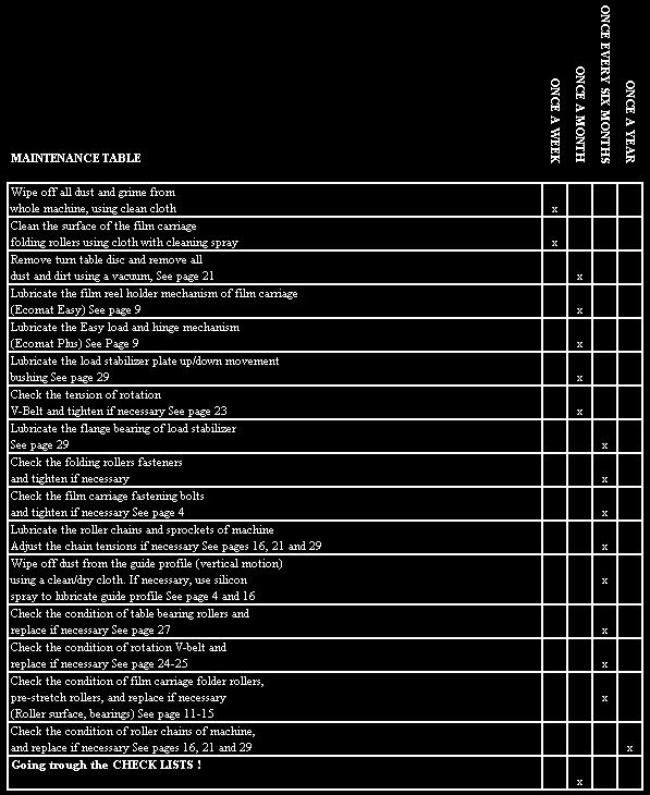
4 Table of contents 3/ Changing the carriage rollers, roller chain and sprocket. 2.0 Maintenance table


5 1. Maintenance of turn table machine 1.1 Film distributor maintenance Check list All film distributor types: - Folding rollers fasteners and bearings - Film distributor fastening to the lifting chain - Looseness between film distributor and guide profile (Condition of guiding rollers and bearings) - Energy transfer chain and cables 4

6 - Photocell and cable 5


7 Ecomat Easy film distributor - Brake roll - roll surface - brake plate - tensioning spring - lever - Pendulum roll - surface - spring - Function of the film reel holder mechanism 6
8 Ecomat Plus film distributor: - Pre-stretch rollers - surface and bearing system - Pre-stretch gears and toothed belt - Dancing roller mechanism - Spring - Inductive sensor 7

9 8 - Easy load mechanism - locking system - hinge system
10 1.1.2 General maintenance actions - Wipe off dust using a clean/dry cloth - Clean the surface of the folding rollers using cloth with cleaning spray (except the pre-stretch rollers) - Lubricate the film reel holder mechanism (Ecomat Easy) - Lubricate the Easy load locking mechanism and hinge (Ecomat Plus) 9
 Phase 1 Open the")


11 1.1.3 Tensioning the pre-stretch toothed belt (Ecomat Plus) Phase 1 Open the service hatch by opening two fastening screws Phase 2 Loosen the fastening screw of tensioning unit and pull the tensioning unit Phase 3 Tight the screw when belt is tense 10
")

12 Changing the pre-stretch toothed belt, pre-stretch rollers and bearings, and pre-stretch ratio (Ecomat Plus) Phase1. Remove the electric motor and motor bed, by opening four fastening screws Now the pre-stretch gears are accessible Phase 2. Loosen the toothed belt tensioning system by opening fastening screw You can now lift of the toothed belt and replace if necessary Phase 3. Open the fastening screw of plastic gearwheel, and lift it off 11


13 Phase 4. You can now lift off the smaller gearwheel, and replace it. SET 150% SET 260% NOTE: If you are changing the pre-stretch ratio, this is the only gearwheel which you have to change, together with a correct toothed belt. Pre.Stretch options: 150% 260% (default, assembled to standard machine) 300% 12


14 Phase 5. Open the fastening screw of aluminium gearwheel, and lift it off Phase 6. Open the four fastening screws of the upper bearing unit and lift it off. Now you can replace the groove ball bearing of upper bearing unit (picture in next page) Phase 7. Lift off the pre-stretch roller and replace it if necessary 13
 1")
 to clockwise direction, to increase dancing roller tension")
15 On left: Upper bearing unit of the pre-stretch roller On right: Lower bearing unit of the pre-stretch roller (bearing bushing) Adjusting the dancing roller tension (Ecomat Plus) Loosen the fastening nut (1) by turning it to anti clockwise direction Turn the adjustment screw (2) to clockwise direction, to increase dancing roller tension Turn the adjustment screw (2) to anti clockwise direction, to decrease dancing roller tension 2 14


16 1.1.6 Changing the brake roller, brake roller tension spring and brake plate (Ecomat Easy) You can first remove the photocell unit to make following steps easier After removing the tension level adjustment nut, you can lift off the bushing and replace the tension spring After removing the lever fastening disc and pulling out the lever, you can lift off the parts above the carriage frame. Loosen the brake plate fastening screw, and remove the brake roller fastening screw. You can now twist of the brake roller and replace necessary parts Changing the guide rollers of the film distributor See pages


17 1.2 Vertical motion maintenance Check list - Roller chain, pulley wheel and pulley wheel fastening mechanism - Gear motor, bearing housing and sprocket - Guide profile of film distributor - Limit switches of film distributor positioning General maintenance actions - Wipe off the dust from the guide profile using a clean/dry cloth If necessary, use a silicon spray to lubricate guide profile. DO NOT USE GREASE OR OIL WHEN LUBRICATING THE GUIDE PROFILE!! - Lubricate the roller chain and sprocket using chain spray. Be careful that the chain spray doesn t reach the guide profile. 16


18 Changing vertical motion roller chain. Phase1 Open the tower fastening screws and tilt the tower to the horizontal position. Use a piece of wood between tower and turn table to avoid damages on the tower (door handle) as shown in the example. 17


19 Phase2 Open the film distributor fastening screws Phase3 Move the film distributor to its upper most position inside the mast Phase4 Remove the photocell and fastening screws of the energy transfer chain Phase5 Slide the film distributor out of the mast 18


20 Because the film distributor is now fully accessible, it is good opportunity to change guide rollers, and do all other maintenance acts. Picture below shows construction of guide roller 19


21 Phase6 Remove the connection plate by opening the fastening screw Phase7 Open the joint link of the roller chain You can now remove the old roller chain Phase8 Replace the sprocket wheel and pulley if necessary. Phase 9 Insert new roller chain and fix the joint link. 20


22 1.3 Turn table maintenance Check list - Roller chain and sprockets - Chain tensioning mechanism - V-belt and belt pulleys - Electric motor and cable - Table bearing rollers - Centre bearing - Table home proximity switch and cable General maintenance actions - Remove the turn table disc and vacuum all dust and dirt - Lubricate the roller chain and sprocket using chain spray - Lubricate the table rollers with silicon spray if necessary 21


23 Removing the turn table disc and cover plate Phase1 Open three fastening screws of disc Phase2 If you have the possibility to use forklift or crane, attach the lifting eye with a lifting belt to lift off the disc Otherwise just slide the disc enough to the side that it is easy to do maintenance Phase 3 Remove cover plate by opening six fastening screws Now turntable construction is fully accessible, and it is easy to do maintenance. NOTE: Be careful while moving on turn table, that you don t step to the table home proximity sensor (surrounded in picture), it can break easily! 22
 - Loose the other nut by turning it to clockwise")
 - Tight both nuts when belt is tense Roller Chain - Loose the other")
 - Tight both nuts when chain is")
24 1.3.4 Tensioning of V-Belt and roller chain V-Belt - Open the motor bed attachment screws (3 pci) - Loose the other nut by turning it to clockwise direction (1) - Tight with other nut by turning it to clockwise direction (2) - Tight both nuts when belt is tense Roller Chain - Loose the other nut by turning it to clockwise direction (3) - Tight with other nut by turning it to clockwise direction (4) - Tight both nuts when chain is tense


25 Changing the roller chain and centre bearing Phase1 Loosen the chain tensioning system (see page 23) Phase2 Open the joint link of the roller chain, remove the chain and replace if necessary Phase3 Open the fastening screw of the centre bearing system You can now lift off the whole system from the axis. Phase4 Open the four bearing case fastening screws You can now replace the centre bearing NOTE: Before inserting new roller chain, check the condition of V-belt as it is a good opportunity to change V-belt if necessary. 24
 and belt tensioning nuts.")
26 Changing the V-belt and transmission pulley bearing Before replacing of V-belt is possible, you must remove the roller chain. See page 24 Phase1 Open the motor bed fastening screws (3pci) and belt tensioning nuts. Phase2 Lift off the electric motor and motor bed Now you can remove the old V-belt and replace it if necessary 25


27 Phase3 Open the fastening screw You can now lift off the whole system and replace the bearings (2pc) 26

28 1.3.7 Changing the table bearing rollers Just lift of the roller and replace it with new one. If you change one roller it would be best to change all rollers at the same time to avoid unbalancing the table. 27
 1.4.")


29 1.4 Load stabilizer maintenance (Ecomat Easy H / Ecomat Plus H) Check list - Press plate up-down movement - Limit switch and cable - Movable bushing - Flange bearing - Electric motor - Roller chain, sprocket and pulley - Carriage rollers - Carriage up-down limit switches and cables 28
 and the flange bearing 1 - Use chain spray to lubricate the roller chain and")

30 1.4.2 General maintenance actions - Wipe off all dust with a clean cloth - Lubricate the press plate movable bushing (1) and the flange bearing 1 - Use chain spray to lubricate the roller chain and sprockets - If necessary, use silicon spray to lubricate the plastic rollers of the carriage Tensioning of load stabilizer roller chain - Turn the tensioning screw clockwise to tighten the roller chain 29


31 1.4.4 Changing the carriage rollers, roller chain and sprocket. Phase1 Remove the movable parts of press plate system by opening fastening screws Phase2 Disconnect the multi-pole plug Phase3 Open the load stabilizer frame fastening screws (2pc) and remove the whole system to somewhere where it is easy to do the maintenance Phase4 Remove the chain tensioning system Phase5 Open the gear motor fastening bolts and remove the motor Phase6 Slide carriage out of the frame You can now change the guide rollers of the carriage, roller chain and sprocket 30
32 31
TECHNICAL MANUAL GTB16N
 TECHNICAL MANUAL GTB16N 1/20 1. INTRODUCTION 1.1 Purpose 1.2 Before Service 1.3 Safety 1.3.1 Hazard Definitions 1.3.2 For Your Safety 1.4 Specifications & dimensions 1.5 Description 2. HYDRAULIC SYSTEM
TROUBLESHOOTING. Ecomat EASY / Girotec WRS Ecomat EASY H / Girotec WRS H V2.0
 TROUBLESHOOTING This manual is for helping you through the possible malfunction solving process. Because most common cause of troubles are wrong kind of machine settings, in chapter one we shortly go trough
62 Deck Idler Kit High Speed
 Part No. 00 FORM NO. -899 6 Deck Idler Kit High Speed For Model 70 Serial No. 99000 to 99000 For Model 7 Serial No. 9900 to 99000 INSTALLATION INSTRUCTIONS Loose Parts Note: Use the chart below to identify
Operations Manual Eagle 1000 Series Stretch Wrapper
 Operations Manual Eagle 1000 Series Stretch Wrapper Models A & B - 1 - READ ALL INSTRUCTIONS CONTAINED IN THIS MANUAL PRIOR TO MACHINE INSTALLATION! - 2 - Contents page 1. Machine Safety Information 1.1
MAINTENANCE - LPX PORTABLE TREATER
 MAINTENANCE - LPX PORTABLE TREATER Proper maintenance of the Portable LPV Treater is critical for peak performance, reliability and accuracy of this system. The following is a guideline for the type of
FREQUENTLY ORDERED PARTS. KING COBRA/ KC ULTRA SIGNODE Model Reflector. 3 round reflector used with above photoeye
 FREQUENTLY ORDERED PARTS KING COBRA/ KC ULTRA SIGNODE Model 8150 FRAME 45-08041-005 Photoeye. Photoeye on safety gate 45-08006-003 Reflector. 3 round reflector used with above photoeye 40-32523-001 Filter,
Installation. Tools. Single Handle Kitchen Faucet With Optional Spray. Maintenance. Safety Tips. Important Points. Need Help? For Model:
 Installation Tools - Basin Wrench - Adjustable Wrenches - Pipe Wrench - Screwdriver - Thread Seal Tape - Supply Lines - Protective Goggles - Silicone Sealant - Pliers - Soft Cloth For Model: 673-6809 Single
Overview SC 800 / 800 propane
 Table 0-1 Spare parts grinding head Overview SC 800 / 800 propane Figure 0-1 Overview of SC-800 Item Reference / art no. Description 1 570627 Handle 2 570039 Sprint to adjust handle 3 911008 Water connection
Illustrated Parts List
 Illustrated Parts List. Ordering Parts For your convenience, replacement parts and accessories can be ordered from ARPAC by fax 24 hours a day. Please have the following information available to ensure
HARD FOLDING TONNEAU COVER INSTALLATION GUIDE
 HARD FOLDING TONNEAU COVER INSTALLATION GUIDE GUIDE FOR FOLD-A-COVER FD3701, FD3702 TRUCK MODEL(S): 1998-2007 FORD F-150 NOTES TO INSTALLER: 70 F when installing. surface. Some trimming of bed liner may
BA-4 AIR-JECT AERATOR OPERATOR S MANUAL & PARTS BREAKDOWN
 BA-4 AIR-JECT AERATOR OPERATOR S MANUAL & PARTS BREAKDOWN Table of Contents Page 02 Table of Contents Page 03 - Welcome to Bannerman Page 04 Declaration of CE Conformity Page 05 Warranty Statement Page
TOSHIBA Thermal Printer B-SX6T/SX8T SERIES. Maintenance Manual. Document No. EO Original Mar., 2006 (Revised ) PRINTED IN JAPAN
 PRINTED IN JAPAN") TOSHIBA Thermal Printer B-SX6T/SX8T SERIES Maintenance Manual Original Mar., 2006 (Revised ) Document No. PRINTED IN JAPAN TABLE OF CONTENTS Page 1. UNPACKING--------------------------------------------------------------------------------------------------------
TOSHIBA Thermal Printer B-SX6T/SX8T SERIES Maintenance Manual Original Mar., 2006 (Revised ) Document No. PRINTED IN JAPAN TABLE OF CONTENTS Page 1. UNPACKING--------------------------------------------------------------------------------------------------------
CALIFORNIA TRIMMER MOWER MAINTENANCE MANUAL
 CALIFORNIA TRIMMER MOWER MAINTENANCE MANUAL 2 Table of Contents Section 1: General Information Page Handle Assembly Instructions 4 Maintenance All Models 6 Oil Change Procedures All Models 9 Height Adjustment
LINDGREN-PITMAN General Maintenance of Lindgren-Pitman Hydraulic Systems & Equipment
 LINDGREN-PITMAN General Maintenance of Lindgren-Pitman Hydraulic Systems & Equipment Page 1 Lindgren Pitman hydraulic driven equipment is designed to give long reliable service with a minimum of repairs
 Page 1 of 21 303-01C Engine 5.4L (3V) 2009 F-150 REMOVAL Procedure revision date: 03/26/2009 Cylinder Head Special Tool(s) 3 Jaw Puller 303-D121 or equivalent Compressor, Valve Spring 303-1039 Holding
Removing and installing cylinder head Removing, installing and tensioning toothed belt
 Page 1 of 10 Removing and installing cylinder head Removing, installing and tensioning toothed belt Special tools, workshop equipment, test and measuring appliances and auxiliary items required 3359 Locking
Manual Hydraulic Unit 110 STH/FS 2+2
 Manual GENERAL INFORMATION GENERAL SERVICE INSTRUCTIONS MOUNTING INSTRUCTION EXPLODED VIEW PARTS LIST DATA FOR HYDRAULIC WINCH WORLD WIDE DISTRIBUTION LIST Serial no.: PS CONGRATULATIONS You have purchased
FREQUENTLY ORDERED PARTS. COBRA XL SIGNODE Model 2100 series. MAINFRAME Motor ¾ HP 90VDC 1725 RPM. Rotates rotor arm round and round
 FREQUENTLY ORDERED PARTS COBRA XL SIGNODE Model 2100 series MAINFRAME 50-20000-005 Motor ¾ HP 90VDC 1725 RPM. Rotates rotor arm round and round 40-82048-001 Brake 5 shaft mount. Stops and holds rotor arm
Base Kit Chain Drivetrain Build Guide
 222fg Base Kit Chain Drivetrain Build Guide August 11, 2017 Chain Drivetrain Build Guide Copyright 2017 REV Robotics, LLC 1 1.1 Description This document outlines the steps required to four wheel, chain
Contents SIGMA. 1. Scissors assy Thread guide and eccentric drive Tucker plate assy
 Contents Contents 1. Scissors assy.... 2-3 2. Thread guide and eccentric drive... 2-5 3. Tucker plate assy.... 2-7 4. Bobbin table with setting elements... 2-9 5. Secondary shaft with ejection elements...
Parts Diagram. To order spare parts, please use diagram and part #s below: Figure 1 Spare Parts Diagram Overview. Figure 3 Heating / Cooling Blocks
 Parts Diagram To order spare parts, please use diagram and part #s below: Figure Spare Parts Diagram Overview Figure 3 Heating / Cooling Blocks Figure 5 Dry Ink Coding Figure 7 Conveyor Table Figure 9
Motion System Components Diagram. Note: #2 Mirror Cover and X-Axis Motor Cover have been removed for visibility. Maintenance.
 Professional Laser System PLS3.75, PLS4.75, PLS6.75 and PLS6.150D Keeping the laser system clean will ensure the highest quality engraving. A clean laser system is the best performing laser system. The
HakkiPilke 38 Easy SPARE PARTS MANUAL FOR LOG SPLITTER MAASELÄN KONE OY
 ENGLISH HakkiPilke 38 Easy SPARE PARTS MANUAL FOR LOG SPLITTER MAASELÄN KONE OY Valimotie 1, FI-85800 Haapajärvi, Finland Tel. +358 (0) 8 772 7300, Fax +358 (0) 8 772 7320 info@maaselankone.fi www.maaselankone.fi
WOOD CHIPPER WC1103 5PQ (8/02/12)
") O P E R A T O R ' S M A N U A L WOOD CHIPPER WC1103 5PQ990101 (8/02/12) To the Owner; Thank-You for choosing a quality product from Frontier Equipment. We strive to give you the best equipment and the
O P E R A T O R ' S M A N U A L WOOD CHIPPER WC1103 5PQ990101 (8/02/12) To the Owner; Thank-You for choosing a quality product from Frontier Equipment. We strive to give you the best equipment and the
1 KW-550T Parts Manual. Table Of Contents
 KW-550T Parts Manual Table Of Contents Drawbar... 2 Central Gearbox - Serial No. 523800-554988... 4 Central Gearbox - Serial No. 523800-554988... 6 Central Gearbox - Serial No. 554989-... 8 Central Gearbox
SLIDING DOOR OPERATOR INSTRUCTION MANUAL
 SLIDING DOOR OPERATOR INSTRUCTION MANUAL (MODEL NO. 1071.101 & 1071.102) Please carefully keep this manual for good maintenance. Caution Be sure the door opener is far away from moisture, vibration, and
ROSTA MOTORBASES ROSTA. Self-Tensioning Motor Mount for Belt Drives. without slippage self-adjusting maintenance-free
 MOTORBASES Self-Tensioning Motor Mount for Belt Drives without slippage self-adjusting maintenance-free Technology Tensioning Motorbase Type MB for Belt Drives The elastic tensioning motorbase type MB,
Kalamazoo Packaging Systems. Division of Kal-Tek, Inc. MODEL 6006H-M S A SEMI-AUTOMATIC STRETCH WRAP SYSTEM OPERATOR S MANUAL 02/01//05
 Kalamazoo Packaging Systems Division of Kal-Tek, Inc. MODEL 6006H-M S A SEMI-AUTOMATIC STRETCH WRAP SYSTEM OPERATOR S MANUAL 02/01//05 1 Table of Contents Warranty...... 3 Assembly... 3 Set up... 4 Film
3D TOUCH. Extruder upgrade. Document version 1.0
 3D TOUCH Extruder upgrade Document version 1.0 1 Summary This manual is for the installation of an additional extruder into the 3D Touch. The procedure is the same for both 1 2 head, and 2 3 head upgrades.
V6 Spring Belt Tensioner
 Dodgerunner s V6 Spring Belt Tensioner Installation Guide Dodgerunner 2007 The bracket consists of two pieces of 1/8" steel bolted together. The main piece is flat plate with welded-on alternator mounting
When to Turn Pins and Bushings
 When to Turn Pins and Bushings 1. The track pins and bushings must be turned when the OD of the bushings is less than 2.11 inches (54 mm). TRACK PINS AND BUSHINGS 5506-5 5. Look for the wear point on the
Floveyor Problem Checklist
 Date: Client: Location: Serial Number: Prior to working on any machinery: Is Floveyor and/or Screwfeeder Electrically Isolated Are all required permits signed off (i.e.: Hot Work Permits, Working at Heights,
READ ALL INSTRUCTIONS CONTAINED IN THIS
 Operations Manual Eagle R2B2 Stretch Wrapper READ ALL INSTRUCTIONS CONTAINED IN THIS MANUAL PRIOR TO MACHINE INSTALLATION! - 1 - Contents page 1. General Information 1.1 Installation Notes 2 1.2 Operational
Manual 28ST Version 1.2
 Manual 28ST Version 1.2 GENERAL INFORMATION Due to the best choice of materials and high precision in manufacturing, we recommend, dismantling, cleaning and lubricating the winch only every second year.
Parts Diagram. To order spare parts, please use diagram and part #s below: Figure 1 Spare Parts Diagram Overview. Figure 3 Heating / Cooling Blocks
 H L - M 8 0 S P A R E P A R T S D I A G R A M Parts Diagram To order spare parts, please use diagram and part #s below: Figure Spare Parts Diagram Overview Figure 3 Heating / Cooling Blocks Figure 5 Conveyor
Removing and installing toothed belt
 Page 1 of 10 Special tools and workshop equipment required Diesel injection pump locking pin -3359- (2x) Pin wrench -T10020- Crankshaft stop -T10050- for engines with circular crankshaft sprocket Locking
USC 2020-TB/3 METRIC UM697TW OPERATION MANUAL & PARTS LISTS
 USC 2020-TB/3 METRIC UM697TW OPERATION MANUAL & PARTS LISTS TABLE OF CONTENTS TABLE OF CONTENTS...1 GENERAL SAFETY RULES...2 DIMENSIONAL DRAWING...3 SPECIFICATIONS OF USC 2020-TB...4 LEGEND OF THE MACHINE...5
11 Maintenance of Handrail Section
 11 Maintenance of Handrail Section V-Type Handrail Q 409 603 11 Maintenance of Handrail Section 11.1 V-Type Handrail Q 409 603 1 Description and Mode of Operation The handrail is provided with a multilayered,
Repair Manual and Spare Parts List
 Hydraulic Drive Unit Type Techn. Doc. No. 362 and Accessories for Pipe Cutting Machine Darstellung kann vom Original abweichen Repair Manual and 580067000_Inst_en_Version_03 Repair General In general,
Contents. ECCO single-phase. 1. Scissors assy Thread guide and eccentric drive Tucker plate assy
 Contents Contents 1. Scissors assy.... 2-3 2. Thread guide and eccentric drive... 2-5 3. Tucker plate assy.... 2-7 4. Bobbin table with setting elements... 2-9 5. Secondary shaft with ejection elements...
TYPICAL EXPERIMENTS Centers of gravity. Force triangle. Force polygon and Bow s Notation. Non- concurrent forces.
 MM 500-001 BASIC PANEL The panel is made from a perforated stainless steel sheet mounted on two supports with adjustable footings. The panel can be tilted, put in portrait or landscape position. Accessories
www MK-Electronic de Parts and Diagrams7
 7 Right Hand Covers 7-2 Left Hand Covers 7-4 Center Covers 7-6 Electronics Module 7-8 Control Panels 7-10 Carriage Assembly 7-12 Scan-Axis Assemblies 7-14 Paper Path Assemblies 7-16 Media Entry Assemblies
Rescue Hoist Ground Support Equipment Electric Version
 Rescue Hoist Ground Support Equipment Electric Version Introduction and Training Information Overview of Training Program Introduction of system Benefits to the Users Theory of Operation When to use the
Aerowerks Toll Free :
 Toll Free : 888-774-1616 Fax : (905)-363-6998 URL: www.aero-werks.com 1 Aerowerks 2018 TABLE OF CONTENTS 1. OPERATION 3 1. START AND STOP INSTRUCTIONS 3 2. PREVENTIVE MAINTENANCE 4-6 2. PREVENTIVE MAINTENANCE
PRODUCT MANUAL 52ST (V.4.0) 52ST FS (V.4.0.F) RON-WPM ST/52STFS-Rev.3
 52ST FS (V.4.0.F) RON-WPM ST/52STFS-Rev.3") PRODUCT MANUAL 52ST (V.4.0) RON-WPM-710021-52ST/52STFS-Rev.3 52ST (V.4.0) p2 EXPLODED VIEW ITEM. 3 MODEL ST - PART No. 540406 ITEM. 3 MODEL ST FS - PART No. 540411 ITEM. 16 - PART No. 589111 ITEM. 15 -
PRODUCT MANUAL 52ST (V.4.0) RON-WPM-710021-52ST/52STFS-Rev.3 52ST (V.4.0) p2 EXPLODED VIEW ITEM. 3 MODEL ST - PART No. 540406 ITEM. 3 MODEL ST FS - PART No. 540411 ITEM. 16 - PART No. 589111 ITEM. 15 -
Moments. It doesn t fall because of the presence of a counter balance weight on the right-hand side. The boom is therefore balanced.
 Moments The crane in the image below looks unstable, as though it should topple over. There appears to be too much of the boom on the left-hand side of the tower. It doesn t fall because of the presence
Engine. Special Tool(s) Compressor, Piston Ring 303-D032 (D81L-6002-C) or equivalent. Compressor, Valve Spring (T93P-6565-AR)
 Compressor, Piston Ring 303-D032 (D81L-6002-C) or equivalent. Compressor, Valve Spring (T93P-6565-AR)") SECTION 303-01C: Engine 5.4L (4V) 2009 Mustang Workshop Manual ASSEMBLY Procedure revision date: 12/12/2008 Engine Special Tool(s) Compressor, Piston Ring 303-D032 (D81L-6002-C) or equivalent Compressor,
SECTION 303-01C: Engine 5.4L (4V) 2009 Mustang Workshop Manual ASSEMBLY Procedure revision date: 12/12/2008 Engine Special Tool(s) Compressor, Piston Ring 303-D032 (D81L-6002-C) or equivalent Compressor,
Turbine Drive Water-Reels. Engine Drive Slurry-Reels. T40M / T45M Squatter (MG1) Parts Manual. Serial No. 340,000 +
 Parts Manual. Serial No. 340,000 +") Turbine Drive Water-Reels Engine Drive Slurry-Reels T40M / T45M Squatter (MG1) Parts Manual Serial No. 340,000 + 700 S. Schrader Ave. Havana, Illinois 62644 Phone: 309-543-4425 Fax: 309-543-4945 Page 1
Turbine Drive Water-Reels Engine Drive Slurry-Reels T40M / T45M Squatter (MG1) Parts Manual Serial No. 340,000 + 700 S. Schrader Ave. Havana, Illinois 62644 Phone: 309-543-4425 Fax: 309-543-4945 Page 1
Operating instructions ErgoPack 600 E
 Operating instructions ErgoPack 600 E Operation of the device is only permitted if the operating instructions have been carefully read and understood before use! Declaration of conformity EU declaration
Timing Chain - Renew ( )
") «Escort 1991/1996 Table of Contents» «Group 21: Basic Engine» «Section 21-09: 2.0l DOHC 16V Engine» «REMOVAL AND INSTALLATION» Timing Chain - Renew (21 314 0) Special Tools 15-030 AUniversal flange holding
«Escort 1991/1996 Table of Contents» «Group 21: Basic Engine» «Section 21-09: 2.0l DOHC 16V Engine» «REMOVAL AND INSTALLATION» Timing Chain - Renew (21 314 0) Special Tools 15-030 AUniversal flange holding
LINDGREN-PITMAN General Maintenance of Lindgren-Pitman Hydraulic Systems & Equipment
 LINDGREN-PITMAN General Maintenance of Lindgren-Pitman Hydraulic Systems & Equipment Page 1 Lindgren-Pitman hydraulic driven equipment is designed to give long reliable service with a minimum of repairs
HYDRAULICS. TX420 & & lower. Hydraulic Tandem Pump Removal. 4. Remove the LH side panel (Fig. 0388).
.") TX420 & 425 240000299 & lower 4. Remove the LH side panel (Fig. 0388). Hydraulic Tandem Pump Removal Note: Cleanliness is a key factor in a successful repair of any hydraulic system. Thoroughly clean all
TX420 & 425 240000299 & lower 4. Remove the LH side panel (Fig. 0388). Hydraulic Tandem Pump Removal Note: Cleanliness is a key factor in a successful repair of any hydraulic system. Thoroughly clean all
Maintenance Manual. Hephestos
 Hephestos 2016 Mundo Reader SL. All rights reserved. The reproduction, copying, distribution, publication or modification of this material is strictly prohibited unless carried out with the express prior
Audi S1 Intake kit. Qty. Description
 Audi S1 Intake kit Description Qty Silicone Intake pipe 1 Vacuum hose 1 Heatshield 1 Bracket 1 Machined inlet 1 Vacuum connector 1 Filter 1 M6x16 cap head bolt 1 Tools Ratchet Extension Torx socket Sockets
Parts list ErgoStrap 600E Frame - Cutter - Strap lifter
 Parts list ErgoStrap 600E Frame - Cutter - Strap lifter Item Quantity Unit Designation Art. No. 1.1 1 ea. Frame with storage compartment (without attachement parts) 600 E 600332 1.2 2 ea. Large wheels
Brake Pad: Service and Repair Front PADS - BRAKE FRONT
 2005 Dodge Truck RAM 3500 4WD Pickup L6-5.9L DSL Turbo VIN C Page 1 Brake Pad: Service and Repair Front PADS - BRAKE FRONT REMOVAL 1. Raise and support vehicle. 2. Remove the wheel and tire assemblies.
Kalamazoo Packaging Systems. Division of Kal-Tek, Inc. SEMI-AUTOMATIC STRETCH WRAP SYSTEM OPERATOR S MANUAL 02/01//05
 Kalamazoo Packaging Systems Division of Kal-Tek, Inc. MODEL 4000M-SA SEMI-AUTOMATIC STRETCH WRAP SYSTEM OPERATOR S MANUAL 02/0//05 Table of Contents Warranty...... 3 Assembly... 3 Set up... 4 Film loading
INSTALLATION AND MAINTENANCE OF TOP LOADING ARM
 INSTALLATION AND MAINTENANCE OF TOP LOADING ARM D TABLE OF CONTENTS 1. INTRODUCTION 04 2. SPECIFICATION OF THE REDLANDS LOADING ARM 04 3. INSTALLING THE LOADING ARM 3.1. Installation Procedures 05 4.
Engine Removal/Installation
 Engine Removal/Installation Make sure jacks and safety stands are placed properly and hoist brackets are attached to correct positions on the engine. (See Section 1). Apply parking brake and block rear
Twenty years in the making, the Flex Series redefines stretch packaging technology
 Twenty years in the making, the Flex Series redefines stretch packaging technology Twenty years and tens of thousands of machines later, Orion Packaging Systems has learned a thing or two about designing
TECHNICAL INFORMATION
 TECHNICAL INFORMATION Model No. Description CONCEPT AND MAIN APPLICATIONS Specification GA4030, GA4530, GA5030 Angle Grinders 100mm (4"), 115mm (4-1/2"), 125mm (5") GA4030/ GA4530/ GA5030 are small diameter
Cable Carriers. Information about further items of our product range is available on request:
 Cable Carriers Information about further items of our product range is available on request: Copper head rails Current collectors Insulators Plastic- and neoprene-cables Junction boxes Cable reels Radio
B DUAL DRUM SANDER
 OWNER S MANUAL B2022-25 DUAL DRUM SANDER INDEX GENERAL SAFETY INSTRUCTIONS Page 3 Specifications Page 4 Features Page 5 Assembly Instructions Initial Assembly Page 6 Installing Abrasives Page 7 Adjusting
A1062 & A1072 AUGER ASSEMBLY MANUAL. Read & understand all instructions pertaining to this auger prior to use!
 A1062 & A1072 AUGER ASSEMBLY MANUAL Read & understand all instructions pertaining to this auger prior to use! Safety Alert Watch for this ALERT Symbol. It identifies potential hazards to Personal SAFETY
I-317. AWWA Check Valves WARNING INSTALLATION AND MAINTENANCE INSTRUCTIONS SERIES 317 WARNING
 Read and understand all instructions before attempting to install, remove, adjust, or perform maintenance on any Victaulic piping products Wear safety glasses, hardhat, and foot protection. Failure to
9. DRIVE AND DRIVEN PULLEYS/ KICK STARTER AGILITY ~6.0kg-m g-m g-m 9-0
 9 5.0~6.0kg-m 3.5-4.5g-m 9 3.5-4.0g-m 9-0 SERVICE INFORMATION...9-1 DRIVE BELT...9-5 TROUBLESHOOTING...9-1 DRIVE PULLEY...9-6 LEFT CRANKCASE COVER...9-2 CLUTCH/DRIVEN PULLEY...9-9...9-2 SERVICE INFORMATION
SPARE PARTS CATALOGUE WINTEX 2000
 P A G E 1 SPARE PARTS CATALOGUE WINTEX 2000 201705 P A G E 2 FIXED FRAME 1 50101015 Spacer ring f. Jack cylinder 2 50101016 Cylinder washer 3 50101017 Sensor fitting 50101018 Fixed frame 5 50101020 Jack
Go-ped ESR750 / ESR750EX Rear Brake Installation Instructions
 Go-ped ESR750 / ESR750EX Rear Brake Installation Instructions This kit provides all the parts you need to install a rear brake on your ESR750 or ESR750EX. It will not work on an ESR Sport, or other Go-ped
PRODUCT MANUAL 12ST (V.4.0) 12ST FS (V.2.0.F) RON-WPM ST/12STFS-Rev.3
 12ST FS (V.2.0.F) RON-WPM ST/12STFS-Rev.3") PRODUCT MANUAL 12ST (V.4.0) RON-WPM-710212-12ST/12STFS-Rev.3 12ST (V.4.0) EXPLODED VIEW ITEM No. 3-537551 ITEM. 3 MODEL 1 ST - PART No. 537551 3.1 p2 2 3.2 3 3.3 4 5 ITEM No. 3-537510 ITEM. 5 - PART No.
PRODUCT MANUAL 12ST (V.4.0) RON-WPM-710212-12ST/12STFS-Rev.3 12ST (V.4.0) EXPLODED VIEW ITEM No. 3-537551 ITEM. 3 MODEL 1 ST - PART No. 537551 3.1 p2 2 3.2 3 3.3 4 5 ITEM No. 3-537510 ITEM. 5 - PART No.
Film-Tech. The information contained in this Adobe Acrobat pdf file is provided at your own risk and good judgment.
 Film-Tech The information contained in this Adobe Acrobat pdf file is provided at your own risk and good judgment. These manuals are designed to facilitate the exchange of information related to cinema
6204 Series Low-Volume Inserter
 204 Series Low-Volume Inserter /2012 MAINTENANCE MANUAL Mechanical description Mechanical description...51 General...52 Covers and plates...52 Electrical components...57 Feeder modules...0 Document feed...4
Maintenance Manual for Embroidery Machine
 1 Maintenance Manual for Embroidery Machine HCR SERIES Version 1.1 HAPPY Industrial Corporation 2 # For safe adjustment and repair # In order to conduct adjustment and repair safely and surely, please
WALKING TREADMILL SF-T1407M USER MANUAL
 WALKING TREADMILL SF-T1407M USER MANUAL IMPORTANT! Please retain owner s manual for maintenance and adjustment instructions. Your satisfaction is very important to us, PLEASE DO NOT RETURN UNTIL YOU HAVE
31/05/2013P:\INVENTORY\SLOW\krone\Krone surplus parts31may12 31May13.xls
 KR/0030413 D8A PULLEY 1 5.95 KR/1394170 D04A PIN 23 2.48 KR/1396650 D01A WEARING SKID (ALSO 1392990) 9 29.95 KR/1396800 D02A DISC 1 87.36 KR/1398000 D05A BLADE 13 1.78 KR/1398820 D07A TINE LONG (N/T) 10
PRODUCT MANUAL 46ST (V.5.0) 46ST FS (V.5.0.F) 50ST (V.2.0) 50ST FS (V.2.0.F) RON-WPM ST/46STFS/50ST/50STFS-Rev.3
 46ST FS (V.5.0.F) 50ST (V.2.0) 50ST FS (V.2.0.F) RON-WPM ST/46STFS/50ST/50STFS-Rev.3") PRODUCT MANUAL RON-WPM-710246-46ST/46STFS/50ST/50STFS-Rev.3 EXPLODED VIEW ITEM. 3 MODEL ST - PART No. 544521 ITEM. 3 MODEL ST FS - PART No. 544530 p2 ITEM. 12 - PART No. 775600/775650 ITEM. 13 - PART No.
PRODUCT MANUAL RON-WPM-710246-46ST/46STFS/50ST/50STFS-Rev.3 EXPLODED VIEW ITEM. 3 MODEL ST - PART No. 544521 ITEM. 3 MODEL ST FS - PART No. 544530 p2 ITEM. 12 - PART No. 775600/775650 ITEM. 13 - PART No.
Operations Manual. Eagle 2000 Series Stretch Wrapper Models B, BE, BHS, EB, EBT, BWS
 Operations Manual Eagle 2000 Series Stretch Wrapper Models B, BE, BHS, EB, EBT, BWS READ ALL INSTRUCTIONS CONTAINED IN THIS MANUAL PRIOR TO MACHINE INSTALLATION! - 1 - Contents page 1. Machine Safety Information
NILFISK BA 500 Service Manual
 NILFISK BA 500 Service Manual Model 66324400 12/94 Form Number 043023 TABLE OF CONTENTS Batteries...21 Brush Drive Belt Adjustment Or Replacement...7 Brush Drive Motor - Carbon brush Inspection... 8 Brush
MODEL NO REPAIR PARTS FRAME
 FRAME 37 FRAME Key No. Part No. Description 90 198573X479 COVER, BOTTOM 91 198574 SCREW, 1/4--20X.63 103 406364X008 IDLER ASSEMBLY, AUGER 105 198576 PIN, HAIR.38DIAX1.64LG 106 198580 PIN, CLEVIS 3/16 DIA
STRINGING EQUIPMENT CATALOGUE
 Antenna Construc on Winches for li ing and passenger li ing STRINGING EQUIPMENT CATALOGUE PULLER FOR LIFTING PASSENGERS Model: SPW 2,5 - P Bull wheel Puller with integrated reel winder switchable between
Folding Golding. Precision High Speed Travel Wheel
 Folding Golding Precision High Speed Travel Wheel Instruction Manual Your new Folding Golding Travel Wheel was designed and handbuilt by Golding Fiber Tools. It has the same precision engineering, fine
Cylinder Head. Special Tool(s) Compressor, Valve Spring (T93P-6565-AR) Heavy Duty Floor Crane or equivalent
 Compressor, Valve Spring (T93P-6565-AR) Heavy Duty Floor Crane or equivalent") SECTION 303-01C: Engine 5.4L (4V) 2009 Mustang Workshop Manual INSTALLATION Procedure revision date: 04/03/2009 Cylinder Head Special Tool(s) Compressor, Valve Spring 303-452 (T93P-6565-AR) Heavy Duty
SECTION 303-01C: Engine 5.4L (4V) 2009 Mustang Workshop Manual INSTALLATION Procedure revision date: 04/03/2009 Cylinder Head Special Tool(s) Compressor, Valve Spring 303-452 (T93P-6565-AR) Heavy Duty
STACKER INSTRUCTION MANUAL
 STACKER INSTRUCTION MANUAL The Mobile Stackers are lifting devices featuring easy, flexible, reliable and safe operation suitable for transportation of loads in such applications as warehouses, manufacturing
Modix Big-60 Assembly Manual Part 2
 Modix Big-60 Assembly Manual Part 2 Version 1.0, October 2017 Menu 1. Motors & End Stop Wiring... 3 2. Controller Wiring Check... 6 3. Extruder Wiring... 7 4. Electronic Box Cover... 9 5. Filament Sensor...
MODEL 345 SERIES II FLAT BED PLASTIC MULCH LAYER OPERATING MANUAL
 MODEL 345 SERIES II FLAT BED PLASTIC MULCH LAYER OPERATING MANUAL Rain-Flo Irrigation 929 Reading Road East Earl, Pa 17519 PH: 717-445-3000 Table Of Contents Cover Disk... 5 Dirt Shield... 5 Drip Pipe...
MODCO TM FIGURE 500 CLOSURE
 CLOSURE SPECIALISTS SINCE 1981 MODCO TM FIGURE 500 CLOSURE INSTALLATION INSTRUCTIONS (!) THE INFORMATION PROVIDED IN THIS DOCUMENT IS VERY IMPORTANT (!) & (!) needs to be shared with everyone involved
1. Remove the crankshaft pulley, engine coolant pump pulley and drive belt. 2. Remove the timing belt cover.
 DISASSEMBLY 1. Remove the crankshaft pulley, engine coolant pump pulley and drive belt. 2. Remove the timing belt cover. 3. Turn the crankshaft clockwise and align the timing marks so as to bring the No.
Assembly Manual. 1/10th Formula 1 Car
 Assembly Manual 1/10th Formula 1 Car Center Pivot Bag 1 3374 - Center Pivot Socket 40194 - Hard Anodized Alum Pivot ball 3254-2-56 *Note - Sometimes it is helpful to slightly over-tighten the top clamp
B. Cylinder Bed Compound Needle Feed Lockstitch Sewing Machine. Instruction Manual and Parts Catalog
 artisan 2618.2-1B Cylinder Bed Compound Needle Feed Lockstitch Sewing Machine Instruction Manual and Parts Catalog Artisan Sewing Supplies, LLC, San Francisco, California CONTENTS INSTRUCTION MANUAL Ⅰ.PRECAUTIONS
Contents. Important Read the manual carefully before using the cycle and save it for future use MONARK EXERCISE AB, Vansbro, Sweden
 EN Manual 927 X Contents Product Information... 5 Facts... 5 Serial number... 5 Operating Instruction... 6 Cycle adjustments... 6 Connection... 6 Workload adjustment... 6 Electronic meter... 7 Brake force
Conversion Kits. Version november 2016
 Conversion Kits Version november 2016 1. Overview Cost effectiveness Epoca I Epoca II DigitAx Epoca II SLM Delta Epoca III Epoca 04 Epoca 05 Epoca 05 2nd Gen. Era SLM 4040 HP 4040 HP-E 5040 E Unica DigitAx
OPERATOR S MANUAL R-Series Roust-a-Bout
 December 2017 OPERATOR S MANUAL R-Series Roust-a-Bout! Before operatingthis lift, readand understandthis Operator s Manual. Become familiar with the potentialhazards of thisunit. Call SUMNER if youhaveanyquestions.
42A FLB WOOD BUNKS 43A FLB ALUMINUM BUNKS ALUMINUM CANTILEVER BOAT LIFT
 Page 1 of 9 42A --- 1265 FLB WOOD BUNKS 43A --- 1265 FLB ALUMINUM BUNKS ALUMINUM CANTILEVER BOAT LIFT Thank you for purchasing our product! Please read these instructions and follow them step by step.*
Brake System H TX, H2.0TXS [B475]; H TX [B466] Safety Precautions Maintenance and Repair
![Brake System H TX, H2.0TXS [B475]; H TX [B466] Safety Precautions Maintenance and Repair](/thumbs/86/93834005.jpg "Brake System H TX, H2.0TXS [B475]; H TX [B466] Safety Precautions Maintenance and Repair") HMM180001 Brake System H1.5-1.8TX, H2.0TXS [B475]; H2.5-3.5TX [B466] Safety Precautions Maintenance and Repair When lifting parts or assemblies, make sure all slings, chains, or cables are correctly fastened,
HMM180001 Brake System H1.5-1.8TX, H2.0TXS [B475]; H2.5-3.5TX [B466] Safety Precautions Maintenance and Repair When lifting parts or assemblies, make sure all slings, chains, or cables are correctly fastened,
Assembly & Operator s Manual
 Assembly & Operator s Manual LiftGator XTR 1200lbs Removable Liftgate TM Visit our website at: www.liftgator.com WARNING: Read the entirety of this manual before using the LiftGator. Failure to do so can
MAIN PRICE LIST. - B 487 Perforated Strip 2 1/2" B 488 Perforated Strip 3 1/2" B 482 Perforated Strip 4 1/2" 9 1.
 PERFORATED STRIPS LENGTH HOLES GBP 1 Perforated Strip 12 1/2" 25 1.63 1 a Perforated Strip 9 1/2" 19 1.51 1 b Perforated Strip 7 1/2" 15 1.39 2 Perforated Strip 5 1/2" 11 0.90 2 a Perforated Strip 4 1/2"
Roller chain idler sprocket units Idler pulley units
 Roller chain idler sprocket units Idler pulley units Roller chain idler sprocket units, idler pulley units Page Product overview Roller chain idler sprocket units, idler pulley units... 334 Design and
IN-VEHICLE REPAIR. Timing Drive Components Camshaft Drive Cassette, LH. Special Tool(s) Holding Tool, Camshaft Sprocket (T97T-6256)
 Holding Tool, Camshaft Sprocket (T97T-6256)") 303-01A-1 IN-VEHICLE REPAIR Timing Drive Components Camshaft Drive Cassette, LH 303-01A-1 Special Tool(s) Holding Tool, Camshaft Sprocket 303-564 (T97T-6256) Adapter for 303-564 303-578 (T97T-6256-A) Holding
303-01A-1 IN-VEHICLE REPAIR Timing Drive Components Camshaft Drive Cassette, LH 303-01A-1 Special Tool(s) Holding Tool, Camshaft Sprocket 303-564 (T97T-6256) Adapter for 303-564 303-578 (T97T-6256-A) Holding
Champion Chippers OPERATOR S MANUAL. Operation & Safety. Includes Model: CX850 CX851. Part #
 OPERATOR S MANUAL Champion Chippers Operation & Safety Includes Model: CX850 CX851 Part # 990026 YOU MUST FILL OUT YOUR WARRANTY REGISTRATION TO ACTIVATE YOUR WARRANTY AND TO QUALIFY FOR PARTS SERVICE!!
2005 Hyundai Tucson LX. On some models, engine is equipped with a timing belt and timing chain. Inspect timing chain when replacing timing belt.
 TIMING BELT NOTE: On some models, engine is equipped with a timing belt and timing chain. Inspect timing chain when replacing timing belt. Removal 1. Remove the engine cover. See Fig. 1. 2. Remove right
BUTTERFLY VALVE - WAFER FAF 3500
 PRODUCTION STANDARDS DN40 DN600 PN 6-10-16 CLASS 150 Design EN 593 Connection Wafer Type ISO 7005-1 EN 1092-1 Face to Face EN 558 Series 20 Marking EN 19 Tests EN 12266-1 Corrosion Protection Electrostatic