Building Instruction of Geeetech Prusa I3 pro W. 3D Printer
|
|
|
- Rosa Gilbert
- 6 years ago
- Views:
Transcription

1 Building Instruction of Geeetech Prusa I3 pro W 3D Printer Version
2 Contents Safety Instructions... 2 Preparations Unfold the box and check the package Assemble the rods of a Y axis Assemble Y axis support plates Mount the Y Motor Build the printing platform Assemble the Y idler Mount the Y axis belt Mount the End stop of Y-axis Assemble the XZ frame and the side panel Assemble the 2 Z motors support Mount the fan Assemble Y - Z axis Mount Z-axis End stop Mount the 2 Z motors Mount the coupling Assemble the X-axis motor end Assemble the Linear bearing and Z axis nut Mount X-axis motor Mount the end stop and the endstop trigger Assemble X axis idler end Assemble the extruder carriage Assemble the X&Z axis Assemble the Z axis top mount Assemble X idler Add the X axis belt Mount the extruder Mount the LCD panel Attach the heated bed Mount the PSU Mount the control board Wiring Tidy out the wires Mount the filament spool Warm tips
3 Safety Instructions Shenzhen GETECH CO.,LTD Building the printer will require a certain amount of physical dexterity, common sense and a thorough understanding of what you are doing. We have provided this detailed instruction to help you assemble it easily. However ultimately we cannot be responsible for your health and safety whilst building or operating the printer, with that in mind be sure you are confident with what you are doing prior to commencing with building or buying. Read the entire manual to enable you to make an informed decision. Building and operating involves electricity, so all necessary precautions should be taken and adhered to, the printer runs on 12V supplied by a certified power supply, so you shouldn t ever have to get involved with anything over 12V but bear in mind there can still be high currents involved and even at 12V they shouldn t be taken lightly. High temperatures are involved with 3D Printing, the Extrusion nozzle of the hot end can run about 230 C, the heated bed runs 110 C and the molten plastic extruded will initially be at around 200 C, so special care and attention should be made when handling these parts of the printer during operation. We wouldn t recommend leaving your printer running unattended, or at least until you are confident to do so. We cannot be held responsible for any loss, damage, threat, hurt or other negligent result from either building or using the printer. 2
4 Preparations 1. Unpack the kit and check if all parts are in the box and check the condition of each part, there might be some damage during shipping. To help you with this, there is BOM in the box and each bag was labeled with part number. 2. Contact our customer service immediately by or through the website if you find any missing or damaged parts. And on the bottom of the BOM, there is a signature of reviewer, please take a picture of it and attach the picture in your mail. 3. Before you start, you can put all the part in order to save your time especially those screws and nuts. Do not mix them up. 4. Ensure you have the necessary skills to carry out the work, or enlist the help of someone who does. 5. Work on a big firm table or bench in a clean dry well-lit area. 6. This kit contains tiny parts; please keep them away from kids under Ask for help if you run into any problems - our contact details are on the website and we will always do our best to resolve any problems encountered. 8. Watch the building instruction videos here on YouTube: Read through each chapter of these instructions to gain an over-all idea of what is involved and how long it might take, before starting on the work described. 3

5 1.Unfold the box and check the package Unfold the package and take all the parts out to check the condition of the items. As you can see, all the parts are packed very carefully. 4


6 Tips: 1. Before assembly, you are advised to put all the parts in order, especially the screws and nuts in order, which will save you a lot of time looking for the required parts. 2. The part ID is corresponding to the number labeled on the bag of every part. Some parts may not have label, you can refer to the pictures on the package list. 5

 Thread the Y axis connect plate W14 in the middle.")
7 2 Assemble the rods of a Y axis Shenzhen GETECH CO.,LTD Step1. Assemble the 2 threaded rods. Required parts Required quantity Part ID Picture φ10 threaded rod 2 NO.5 Y axis connect plate 2 NO.W14 Spring washer 6 NO.17 M10 Washer 8 NO.8 M10 Nut 8 NO.12 Thread the nuts and washers into the two M10 threaded rods separately. The order should be: 1) Thread the Y axis connect plate W14 in the middle. 2) Thread the M10 washer > M10 spring washer >M10 nut > M10 nut > M10 washer on the left 3)(right)Thread the M10 washer < M10 spring washer < M10 nut < M10 nut< M10 spring washer < M10 washer on the right 6


8 Step2. Assemble the 2 smooth rods 7
9 Required parts Required quantity Part ID Picture φ8 smooth rod 2 NO.3 LM8UU Linear bearings 3 NO.32 Screw locking ring 2 NO.18 1Take out the 410mm smooth rod Slide 3 Linear bearings on the smooth rods,one smooth rod with two pieces and another with one. Before you slide the bearings please make sure they are clean. 2 Slide the screw locking ring on the end of the smooth rod. 8

 2 NO.")
10 3 Assemble Y axis support plates Required parts Required quantity Part ID Picture Support plate of Y axis(front) 2 NO. W9 W 10 Support plate of Y axis(rear) 2 NO. W 11 W 12 M10 washer 4 NO.8 M10 nut 4 NO.12 9

11 Step 1. Insert 2 threaded rods into rear support plates separately through the bottom mounting hole; please note the sequential order of two support plates.(as below picture) Step 2.Slightly fix the threaded rods and the rear support plate with M10 nut and M10 washer. Step 3.Insert the smooth rods with lock ring on into the rear support plates through the upper mounting hole; then slightly fix the lock ring. Step 4.Separately insert the another end of the smooth rods and the threaded rods into the upper and the lower of the mounting holes of the front support. Step5. Slightly fix the threaded rods and the wood plate with M10 nut and M10 washer. 10


12 * Tips: Try to keep the thread rods parallel and the four wood pieces parallel. The Y-axis must be a rectangle, that is the rods on both side should be parallel, so is the front and back plate. Otherwise it will cause obstruction for the belt later. You can use a Digital Caliper to measure. 4 Mount the Y Motor Required parts Required quantity Part ID Picture Y motor fix plate 1 NO. W13 Stepper motor 1 NO.58 Pulleys 1 NO.39 M3 x 10mm screw 3 NO.22 M3 x 16 mm screw 2 NO.24 11
 Step2.")
13 M3 square nut 2 NO.15 M3 washer 5 NO.7 Step1. Mount the pulley on the motor shaft, one of the screws should be screwed on the flat side of the shaft. Screw it as tight as possible. (Note the direction of the pulley as below picture) Step2. Then screw the motor on the Y motor holder with 3 M3 x 10mm screws and M3 washers. 12

14 Step3. Push the Y Motor holder tab into the square hole in Rear Plate. Then fix it with 2 M3x16mm screws, M3 Washers and M3 Square Nuts. 13


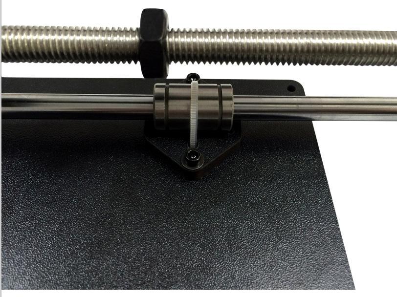
15 5 Build the printing platform Required parts Required quantity Part ID Picture Y platform support 1 NO.W15 Y bearing block 3 NO.W16 14


16 Belt mount 1 NO.A17 Belt bracket 1 NO.47 Zip ties 4 NO.62 M3 x 12 mm screw 3 NO.23 M3 x 16 mm screw 6 NO.24 M3 nut 8 NO.10 M3 square nut 1 NO.15 M3 washer 9 NO.7 Step 1.Separately mount the 3 bearing blocks on the platform support plate with M3 x 16mmscrews and M3 washer, then fix the other ends with M3 nuts. 15

17 Step 2.Install the belt bracket on the belt-mount with 2 M3 x 12mm screws, M3 washer and M3 nut. 16

18 Step3. Mount the belt mount on the platform support plate with M3 x 12mm screw, M3 washer and M3 square nut on the same side with the bearing block. (Note the direction: The direction of the belt brackt is same as the bearing block) 17

19 Step 4.Put the build platform support on the Y- Axis holder, and then get it zip-tied to the 3 linear bearings of Y- Axis together. (Note the direction: The belt bracket is in the line with the pulley of Y motor.) 18
20 19


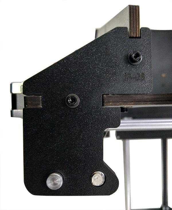
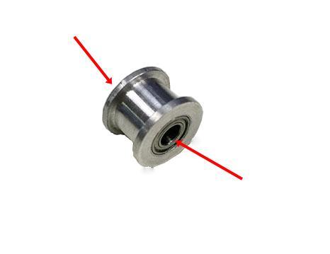
21 6 Assemble the Y idler Shenzhen GETECH CO.,LTD Required parts Required quantity Part ID Picture Ball bearing 2 NO.41 Driven wheel holder 1 NO.37 Driven wheel 1 NO.40 M3 x 16 mm screw 1 NO.24 M3 wing nut 1 NO.14 M4 x25 mm screw 1 NO.29 M4 Lock nut 1 NO.13 Step1. Thread the M3 x 16mm screw through the driven wheel holder. Step2. Put the driven wheel with ball bearing into the driven wheel holder; Thread the M4 x25mm screw through the driving wheel. Lock the other end with a M4 lock nut. You may need a pair of pliers to tighten locking nut. 20
22 21
23 *Do not screw it too tight, you should leave enough room for the wheel to turn freely. Step4. Mount the assembled bearing holder onto the front support plates from inside to outside. And screw it with a wing nut. 22


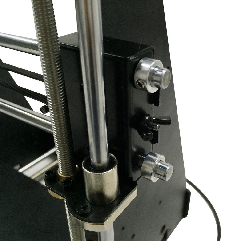
24 7 Mount the Y axis belt Required parts Required quantity Part ID Picture Timing Belts 1 NO.35 Step1. Insert one end of the belt in the groove bracket. Pay attention to the tooth mesh of the belt and the groove. Step2. Thread the other end of the belt though the pulley of the Y motor. 23

25 Step3. Thread the belt though the driven wheel. Lock the wing nut. Do not tighten too much at this step. Step4. Taut the belt into the belt bracket, tightly pull and confirm its length, then cut off the spare part. Insert the end of the belt in the groove bracket Step 5.Tight the wing nut. Tips: The pulley, the belt bracket and the driven wheel must be flush to ensure the printing platform to move smoothly. 24

26 8 Mount the End stop of Y-axis Required parts Required quantity Part ID Picture End stop 1 NO.52 M2.5 x 16 mm screw 2 NO.20 M2.5 Hex nut 2 NO.9 M2.5 washer 2 NO.6 Mount the end stop on the rear support plate of Y axis with M2.5 x 16mm screw, M2.5 washer and M2.5 Hex nut. 25

 1 NO.")
27 9 Assemble the XZ frame and the side panel Required part Required quantity Part ID Picture X-Z frame (up) 1 NO. W1-A 26


28 X-Z frame (bottom) 1 NO.W1-B Left side frame 1 NO.W2 Right side frame 1 NO.W3 M3 x 16 mm screw 6 NO.24 M3 square nut 6 NO.15 M3 washer 6 NO.7 Step1. Screw up the X-Z frame (up) and the side panel with M3 x 16mm screws, M3 washer and M3 square nuts. 27
29 28
30 29
 and the side panel with M3")
31 Step2. Screw up the X-Z frame (up) and the side panel with M3 x 16mm screws; M3 washer and M3 square nuts. 30


32 Note the direction of the holes of LCD knob. It is on the right. 10 Assemble the 2 Z motors support Required parts Required quantity Part ID Picture Z motor fix plate (left) 1 NO.W4 Z motor fix plate (right) 1 NO.W5 31

")
33 Z motor support plate 3 NO.W6 Z motor support plate 1 NO. W7 M3 x 16 mm screw 10 NO.24 M3 square nut 10 NO.15 M3 washer 10 NO.7 Step 1.Assamble Z motor support plate W6,W7 with Z motor fix plate (left) together with M3 x 16 mm screws, M3 washer and M3 square nuts. 32
")
34 Step 2.Assamble 2 Z motor support plates W6 with Z motor fix plate (right) together with M3 x 16 mm screws, M3 washer and M3 square nuts. 33

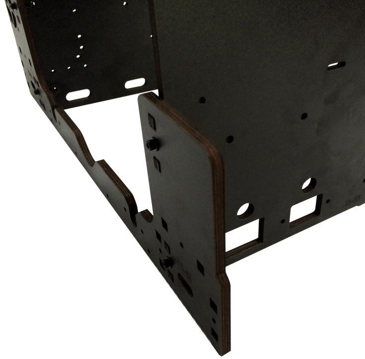
35 NOTE THE SMALL HOLE Step 3.Separately screw up the assembled Z motor supports to the left and rigt corners of the main frame with M3 x 16mm screws and M3 square nuts. 34
36 (Left) 35

37 (Right) 36


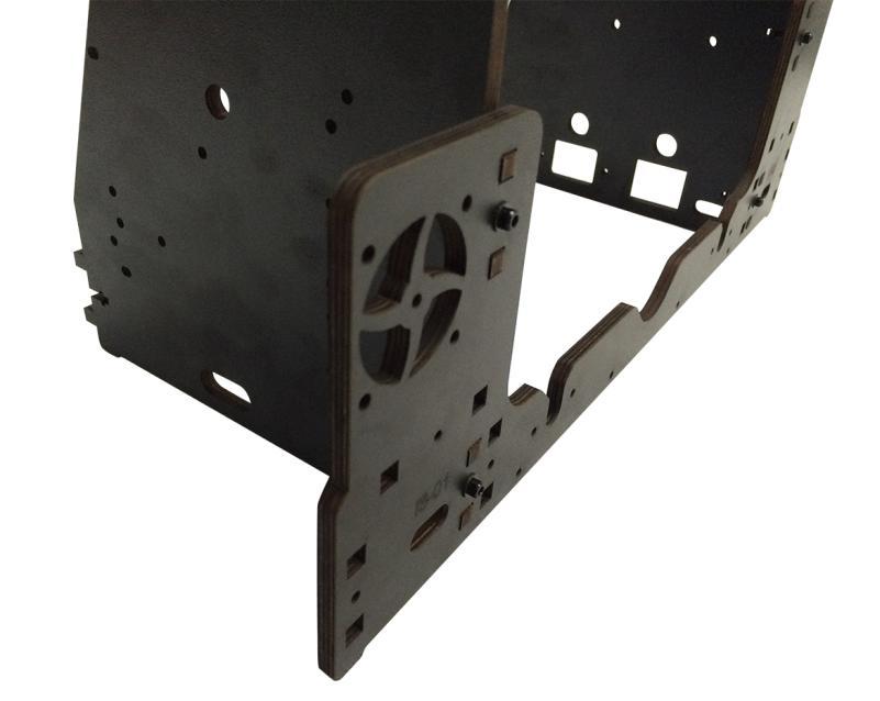
38 11 Mount the fan Required parts Required quantity Part ID Picture Fan 1 NO.49 M3 x20 mm screw 4 NO.25 M3 nut 4 NO.10 M3 washer 4 NO.7 Fix the fan on the left back side of the frame with 4 M3 x 20 screws, M3 washer and 37
 12 Assemble Y - Z axis Required parts Required quantity Part ID Picture M3 x 16 mm")
39 M3 nuts. Mind the direction of the fan. (The side with the label is outward.) 12 Assemble Y - Z axis Required parts Required quantity Part ID Picture M3 x 16 mm screw 6 NO.24 38

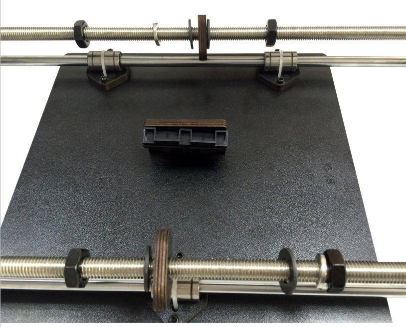
40 M3 nut 4 NO.10 M3 square nut 2 NO.15 M3 washer 6 NO.7 Step1. Put the Y axis between the main frame. W14 is at the front of the frame. 39

41 Step2. Screw up the Y axis rear plate and the side panel with M3 x16mm screws,m3 washer and M3 square nuts. 40

42 Step3. Screw up the main frame to the Y axis connecting plate with 4 M3 x 16mm screws, M3 washer and M3 nuts. 41

43 Step4. Screw up the M10 nuts on Y axis. 13 Mount Z-axis End stop Required parts Required quantity Part ID Picture End stop 1 NO.52 M 2.5 x 16 mm screw 2 NO.20 M 2.5 nut 2 NO.9 M 2.5washer 2 NO.6 42

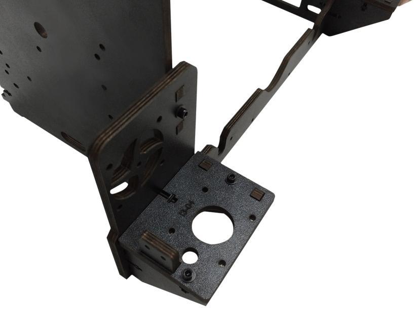
44 Mount the endstop on the Z -axis motor base (left) with M2.5 x 16mm screw,m2.5 washer and M2.5 hex nut. 14 Mount the 2 Z motors Required parts Required quantity Part ID Picture 43

45 Stepper motor 2 NO.58 M3 x 10mm screw 8 NO.22 M3 washer 8 NO.7 Step1. Thread the wires of the motors through the holes of the main fame. Then put the motor under the motor base. Step2. Screw up the motors with 4 M3 x 10mm screws and M3 washer. 44


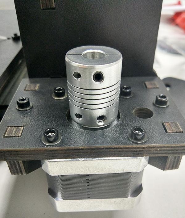
46 Do the same with the other Z motor according the above steps. 15 Mount the coupling Required parts Required quantity Part ID Picture Coupling 2 NO.38 Step1. Fix the two couplings on both of the motor shaft. Please note: 45

47 1. The opening of both end, one is 5mm, another is 8mm, connect the 5mm hole to the motor shaft. 2. Screw the jimmy screw of the 5mm part on the upper part of the flat side of the motor shaft tightly; you can see the boundary in the inner of the coupling. 46

48 Do the same with the coupling of the right motor shaft according the above steps. 47
49 48

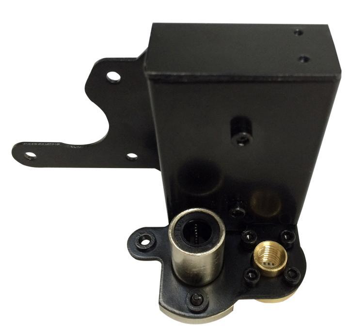
50 16 Assemble the X-axis motor end 16.1 Assemble the Linear bearing and Z axis nut Required parts Part ID Required quantity Picture Z-axis nut No.16 1 X-axis left end No.M1 1 Linear Bearings No M3 x 6mm screw No Step1. Mount the linear bearing on X-axis motor end from bottom to up. Fix it up with M3 x 6mm screws. Step2. Mount the Z nut on the X-axis left end from bottom to up, fix with M3 x 6mm screws. 49
51 50


52 16.2 Mount X-axis motor Required parts Part ID Required quantity Picture Stepper motor No.58 1 Pulleys No.39 1 M3 x 6 mm screw No M3 washer NO

53 Step 1.Mount the pulley on the motor shaft and fix it from the flat side. Note the direction of the pulley: the gear is at the bottom. Step 2.Mount the stepper motor to the motor end with 3 M3x6mm screws and M3 washers. 52

54 16.3 Mount the end stop and the endstop trigger Required parts Part ID Required quantity Picture M2.5 x 8 mm screw No End stop No.52 1 M3 x 35 mm screw No M3 washer NO


55 Spring NO.31 1 Step1. Mount the endstop on the top of the X-axis motor end with 2 M2.5 x 8mm screws. Mind the direction of the endstop paddle. Step2. Thread a M3 washer> spring> M3 washer in order to the M3x35mm screw. Step3. Thread the M3x35mm screw into the screw hole. 54

56 17 Assemble X axis idler end Shenzhen GETECH CO.,LTD Required parts Part ID Required quantity Picture Z-axis nut No.16 1 X axix right end No.M2 1 Linear Bearing LMH8LUU No M3 x 6mm screw No Step1. Mount the linear bearing on X-axis idler end from bottom to up. Fix it up with M3 x 6mm screws. Step2.Mount the Z axis nut on the bottom of X-axis idler end with 4 M3 x 6mm screws. 55


57 18 Assemble the extruder carriage Required parts Part ID Required quantity Picture Bearing mount No.M3 1 56
58 Bearing Bracket No.M4 4 Extruder bracket No.M5 1 Linear Bearing LM8LUU No.33 2 Belt bracket No.47 1 M3x6mm screw No M4x6mm screw No M3 nut No.10 2 Step1. Fix the 4 Bearing Brackets on the back of the X Carriage loosely with M3x6mm screws. 57


59 Step2. Insert the linear bearing into the bearing mount slot and tight the screw. 58

60 Step3. Fix the belt bracket on the back of the carriage with 2 M3 x6mm screws and M3 hex nuts. 59

61 Step3. Fix the extruder holder on the front side of the X carriage with M4x6mm screws. 60

62 19 Assemble the X&Z axis Required part Part ID Required number Picture L300mm Threaded rod L322mm Smooth rod L390mm Smooth rod No.4 2 No.1 2 No

63 Screw locking ring No.18 4 Step1.Use the file to polish the holes on the X axis motor end and the idle end to make sure the L390mm Smooth rod can thread in to them smoothly. (8 holes in total) Step2. Thread the L300 threaded rod to the nut of both end of X axis. Keep both end of X axis at the same place of the rod, you are advised to measure the distance of the both side so that they are at the same level when you put them up. 62

64 Step3. Plug the threaded rod on the X motor end to the left coupling on the left motor of the Z axis. Then thread the 320mm smooth rod into the linear bearing. 63
65 64

66 Step4. Thread the L390mm smooth rod into the X motor end > thread the extruder carriage on the two rods. Step5. Thread the two X axis smooth rods into the hole of X idler end. 65

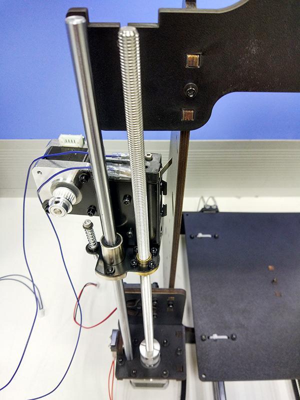
67 Step6. Plug the vertical threaded rod into the coupling on the right motor of the Z axis. Then thread the 320mm smooth rod into the linear bearing. 66

68 20 Assemble the Z axis top mount Required part Part ID Required number Picture 67
69 Z axis top mount No.W8 2 M3 x 16mm screw No.24 4 M3 square nut No.15 4 Screw locking ring No.18 2 M3 washer No. 7 6 Step1. Put the locking ring on the two smooth rods separately. Step2. Add the Z top mount (No.W8) to the top of W1. Slowly rotate the rods into the holes, or add some lubricants on the rods. Step3. Screw up the top mount, the main frame and the side panel with M3 x 16mm screw and M3 Square nut. Step4. Screw up the locking ring on smooth rods. 68
70 69

71 Step 5.After fixing the top mount, the length of X-axis and Z-axis is confirmed. Next step is to screw up the both end of X-axis with the locking rings. 70
72 71
73 Note: It is very important to make sure the verticality of the smooth rod and the threaded rod of Z axis, the horizontality of X axis, otherwise it will impede the movement of Z axis. 21 Assemble X idler Required parts Part ID Required quantity Picture Drivenwheel holder No

74 Driven wheel No.40 1 Ball bearing No.41 2 M3 x40mm screw No.27 1 M4 x 25mm screw No.29 1 M4 Lock nut No.13 1 Wing nut No.14 1 Step1. Thread M3 x 40 screw through the driven wheel holder. Step2. Insert the driver wheel with the ball bearing into the middle of the driving wheel holder. Put the M4 x25 screw through the driving wheel. Lock the other end with a M4 lock nut. You may need a pair of pliers to tighten locking nut. 73
75 74

76 *Do not screw it too tight, you should leave enough room for the wheel to turn freely. 22 Add the X axis belt Required part Part ID Required quantiry Picture Timing belt No.36 1 Step1. Insert one end of the belt into the groove. Pay attention to the tooth mesh of the belt and the groove. Step2. Thread the belt through the belt driven wheel and put the M3 x 40 mm screw of he driving wheel into the X idler end, lock it with a wing nut. Do Not screw too tightly. Step3. Thread another end of the belt through the X motor end around the pulley. Step4. Insert another end of the belt into the groove, pull tightly and cut the spare part. Confirm the length of the belt.then insert the belt into the groove. 75


77 Step5. Taut the belt and tighten the wing nut on the idle end. 76

78 *Note the direction of the driven wheel, the side with lock nut should be outward, or it will scratch the wood plate. 77
79 78


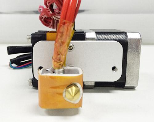
80 23 Mount the extruder Required parts Required Number Part ID Picture Extruder 1 NO.59 M4 x 6mm screw 2 NO.28 Mount the assembled extruder on the extruder holder and use 2 M4 x 6 mm screws to fix. 79
81 80


82 24 Mount the LCD panel Required parts Required quantity Part ID Picture LCD NO.61 Spacer 4 NO.43 M3 x 16mm screw 4 NO.24 81


83 M3 nut 4 NO.10 Konb 1 NO.48 M3 washer 6 No. 7 82

84 25 Attach the heated bed Required parts Required quantity Part ID Picture Heat bed set 1 NO.55 M3 x35mm screw 4 NO.26 M3 washer 12 NO.7 83
85 Spring 4 NO.31 Dovetail clamp 4 NO.44 Wing nut 4 NO.14 Borosilicate glass 1 NO.56 Mount the heat bed on the platform with 4 M3 x35 screws, M3 washers and wing nuts. Clamp the heat bed and the glass sheet. *The soldered side is better to be attached downwards. The order should be: M3 x35mm screw washer Heat bed Spring washer Wood support plate washer Wing nut 84


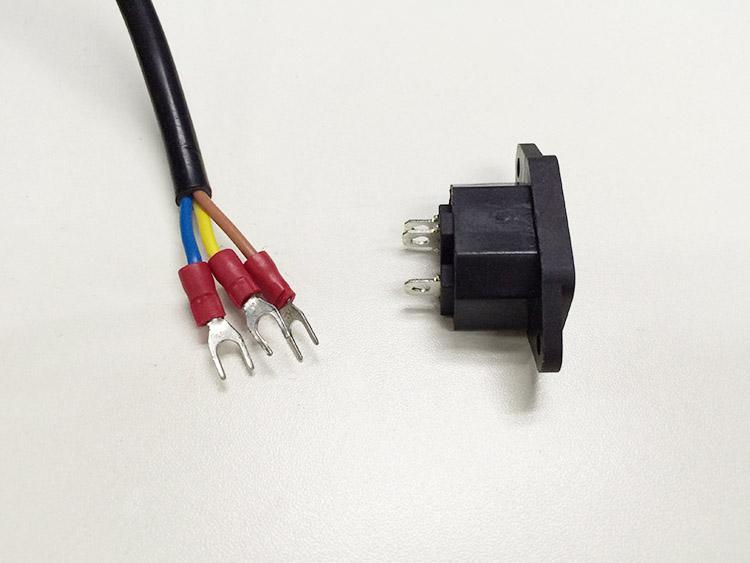
86 26 Mount the PSU Required parts Required quantity Part ID Picture Power supply unit 1 NO.57 M3 x 10 mm screw 3 NO.22 M3x16mm Countersunk head 2 NO.30 screw M3 nut 2 NO.10 85

87 M3 washer 5 No. 7 Power input cable 1 NO.53 Power output cable 1 NO.54 Step1. Take off the wires connected to the socket; before you do, please take a photo of the wire connection, in case you connect them wrongly later. 86
88 87


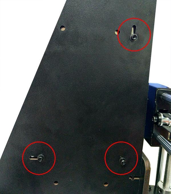
89 Step2. Mount the socket on the bottom of the right side panel with 2 M3 x 16 Hex Counter- sunk-head screws,m3 washer and M3 hex nut. 88

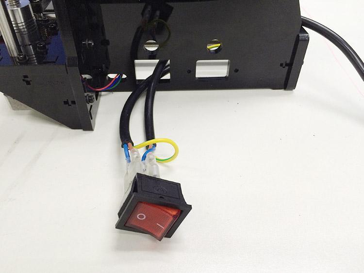
90 Step3. Put the power outout cable in the bottom of the printer, then thread it out from the hole on the right side panel. 89

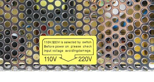
91 (Use the transparent pictures of Pro W to conveninently display the inner part to the user.) Step4. Mount the PSU (Power supply unit) on the right side panel with 2 M3 x 10mm screws,m3 washers. Pay attention to the switch on the right side of the PSU, there are two options of voltage: 110 V and 220V, choose according the standard in your country. As shown in the following picture. Remove the yellow paper; you can use some hard sticks to reach the switch. 90
92 91
93 92

94 Step5. Now we can connect the wires to the PSU. Mind the color of the wires. The wrong connection of the wire will cause serious damage to the PSU and even to the control board of the printer. As you can see, there are 7 wires terminals in total. Note the correspondence between the color of wires and the connector. After finish the connecting, close the cover of the connector in case any electric shock. Brown------L Blue N Yellow GND Red V Black------COM 93


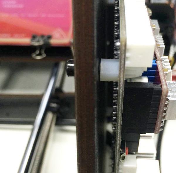
95 27 Mount the control board Required parts Part ID Required quantity Picture Control board No.60 1 Sticker No.46 1 Heat sink No
96 Spacer No.42 4 M3 x 10 mm screw No.22 4 M3washer No You can also mount the board after you finish the wiring so that you can see the Silk print on the back of the board 2. Some connectors on the board may vary in different batches, but the layout of the board are the same, it will not affect the wiring. Step1. Cut the sticker into small pieces. Past the heat sink onto the chip of the A4988 drivers (on the main board). Step2. Insert the spacer into the holes of the board from back to front, Mount the board kit on the left side panel with 4 M3 x 10mm screws and M3 washers on the side panel. Note the direction of the board; the section insered A988 is are upwards. 95
97 96

98 28 Wiring Mainboard:GT2560 Before you start wiring; please take a look at the wiring schematics. 97

99 Note: Different batches of main board, the color and the model of the heating terminal may be different,but all layout of interface is same. You can see original picture here. For your convenience, the first two steps are finished, you can directly start fron step 3. Step1. The subdivision of stepper motor can be setup by jumper cap, plug all the jumper caps. 98

100 Step2. Plug the 4 A4988 into the stepper motor driver slot. Mind the directions of A


101 Step3. Connect wires for motors. 1) Connect wires for X-axis motor. 2) Connect wires for Y-axis motor. 100
102 3) Connect wires for 2 Z-axis motors. (Z-axis motors-left) 101


103 (Z-axis motors-right) 4) Connect the cables of Extruder motors. There are two interfaces of the extruder motors,here is coonecting with the extruder
 Connect heating wires for heatbed. 2) Connect heating wires for extruder 1. 103")
104 Step4. Connect heating wires. Loosed the screws in the green terminal and put the red wires into the slot and screw it up. * There is no + and - for heating wires 1) Connect heating wires for heatbed. 2) Connect heating wires for extruder


105 Step5. Connect wires for thermistor. 1) Connect wires for thermistor of heatbed. 2) Connect wires for thermistor of extruder

106 Step6. Connect wires for endstop. Connect wires for endstop of X-axis at X-Min. 2) Connect wires for endstop of Y-axis at Y-Min. 105
107 3) Z-Min Connect wires for endstop of Z-axis at Z-Min. Step7. Connect wires for Fan. 1) Connect fan for control board at FAN3. 106

108 2) Connect fan for extruder at FAN1. 107

109 Step8. Connect wires for LCD panel. There are two cables, one is for LCD encoder, the other is for SD card, do not connect them reversed. 108

110 Step9. Connect wires for power input. 109

111 That is all for the wiring of GT2560.If any questions, please contact with us in any time. 29 Tidy out the wires Use the wire coil to tie put those wires together. There are holes on the wood plates for the wires, you can arrange them as you like. 110


112 30 Mount the filament spool. Shenzhen GETECH CO.,LTD Required parts Required quantity Part ID Picture Filament side panel M3 x 16 mm scew 4 NO.24 M3 square nut 4 NO.15 PVC tube 2 111
113 The whole printer assembly work is already done. 31 Warm tips Before even attempting the first print it is vital that the printer is correctly calibrated. Skipping or rushing this step will result in frustration and failed prints later, More preparation may quicken the speed in doing work. so it is important to take the time to make sure the machine is correctly set up. Each machine may have its own calibration procedure and this manual will not attempt to cover all the variations. Instead here is a list of key points that should be addressed. 112
114 Frame is stable and correctly aligned. Rods are correctly aligned Belts are taut. Driving wheel turns smoothly Bed is level in relation to the path of the extruder. Filament rolls freely from the spool, without causing too much tension on the extruder. Current for stepper motors is set to the correct level. Wires are correctly connected Couplings and pulleys are fixed tightly Firmware settings are correct including: axis movement speeds and acceleration; temperature control; end-stops; motor directions. Extruder is calibrated in the firmware with the correct steps per mm of filament. The point regarding the extruder step rate is vital. Slic3r expects that the machine will accurately produce a set amount of filament when told to do so. Too much will result in blobs and other imperfections in the print, too little will result in gaps and poor inter-layer adhesion. For how to set up the printer, please visit: To know how to set up, please refer to the user manual. 113
Assembly Instructions of Geeetech Aluminum Prusa I3
 Assembly Instructions of Geeetech Aluminum Prusa I3 CONTENT Safety Instructions... 3 Preparation... 4 1. Unfold the box and check the package... 1 2. Assemble Y axis... 1 3. Build the printing platform...
Assembly Instructions of Geeetech Prusa I3 A pro
 Assembly Instructions of Geeetech Prusa I3 A pro (Version 04-11-2016) CONTENT Safety Instructions... 3 Preparation... 4 1. Unfold the box and check the package... 1 2. Assemble Y axis... 1 3. Build the
Building Instructions of Geeetech Prusa I3 M201
 Building Instructions of Geeetech Prusa I3 M201 (Version 11-25-2016) CONTENT Safety Instructions... 1 Preparation... 2 1. Assemble the threaded rods of Y axis... 3 2. Assemble the front and back support
Building Instructions of Geeetech Prusa I3 M201
 Building Instructions of Geeetech Prusa I3 M201 (Version 04-11-2016) CONTENT Safety Instructions... 1 Preparation... 2 1. Assemble the threaded rods of Y axis... 3 2. Assemble the front and back support
Assemble Manual of Geeetech Acrylic Prusa I3 (8mm)
") Assemble Manual of Geeetech Acrylic Prusa I3 (8mm) Warning: Shenzhen GETECH CO.,LTD. This kit contains tiny parts; please keep them away from kids under 3.. Building and operating 3D printer involves electricity,
Assemble Manual of Geeetech Acrylic Prusa I3 (8mm) Warning: Shenzhen GETECH CO.,LTD. This kit contains tiny parts; please keep them away from kids under 3.. Building and operating 3D printer involves electricity,
Delta Rostock mini G2S Pro 3D Printer
 Delta Rostock mini G2S Pro 3D Printer Copyright Declaration The copyright of this manual belongs to the Shenzhen GETECH CO., LTD. (hereinafter referred to as the "Geeetech"), and all rights reserved. No
Geeetech Prusa I3 M201
 Geeetech Prusa I3 M20 Copyright Declaration The copyright of this manual belongs to the Shenzhen GETECH CO., LTD. (hereinafter referred to as the "Geeetech"), and all rights reserved. No part of this specification
Geeetech Prusa I3 M201. Assembly Manual
 Geeetech Prusa I3 M20 Assembly Manual SUPPORT Thanks for choosing Geeetech, we strive to provide a satisfied and pleasant shopping experience for you, but we do understand there may be some questions you
Copyright Declaration
 Geeetech Prusa I3 X Copyright Declaration The copyright of this manual belongs to the Shenzhen GETECH CO., LTD. (hereinafter referred to as the "Geeetech"), and all rights reserved. No part of this specification
Prusa i3 Printer Assembly Guide
 Prusa i3 Printer Assembly Guide Special thanks to Carlos Sanchez and Miguel Sanchez for the graphics. All graphics captured from their great animation: http://www.carlos-sanchez.com/ Prusa3/ For copyright
TL4076 Top 5 Tips Get to know your TL4076
 TL4076 Top 5 Tips Get to know your TL4076 Thermal Break with Teflon liner (behind fan) Hot End Assembly Fan Heat Block Extruder with toothed gear(brass) and idler (steel) Filament Guide Tube Nozzle Cable
5. E-axis assembly. 5. E-axis assembly. Written By: Jakub Dolezal manual.prusa3d.com/ Page 1 of 40
 5. E-axis assembly Written By: Jakub Dolezal 2018 manual.prusa3d.com/ Page 1 of 40 Step 1 Tools necessary for this chapter Needle-nose pliers for zip tie trimming. 2.5mm Allen key for M3 screws 2mm Allen
5. Extruder Assembly
 5. Extruder Assembly Guide for the assembly of the Extruder. Written By: Josef Prusa 2018 manual.prusa3d.com/ Page 1 of 24 Step 1 Get the necessary tools 2.5 and 1.5 mm Allen key Needle-nose pliers 2018
JGAURORA 3D PRINTER MODEL: A5 USER GUIDE
 JGAURORA 3D PRINTER MODEL: A5 USER GUIDE Contents ----3D Printer User Guide 1. Preface... 2 1.1 Introduction...2 1.2 Safety advice... 2 1.3 Filament requirements...2 1.4 Environmental requirements...2
Modix Big-60 Assembly Instructions Part 1
 Modix Big-60 Assembly Instructions Part 1 Version 1.0, October 2017 Menu 1. X Idler Pulley Assembly... 3 2. Connecting X Axis Brackets to Z Profiles... 4 3. Assemble X Rails on X Top Profiles... 6 4. Assemble
Pi Instruction Manual. Mechanical
 Pi3 2014 Instruction Manual Document No MANUAL WBS Pi3 2014 DIY REV01 Mechanical 3D LabteK Model 1 / 37 Content Page Introduction 2 Printed Parts 3 1, Mechanical 4 1,1 Frame Assembly 6 1,2 Y Axis Assembly
Upgrade v3 to v3.2. SeeMeCNC Guides. Upgrade v3 to v3.2. Rostock Max v3 Uprgade to v3.2. Written By: SeeMeCNC seemecnc.dozuki.
 SeeMeCNC Guides Upgrade v3 to v3.2 Rostock Max v3 Uprgade to v3.2 Written By: SeeMeCNC 2018 seemecnc.dozuki.com/ Page 1 of 34 INTRODUCTION This guide is intended to Upgrade a Rostock Max v3 to a Rostock
Written By: Josef Prusa
 7. PSU & Heatbed assembly PSU and Heatbed guide Written By: Josef Prusa 2017 manual.prusa3d.com/ Page 1 of 17 Step 1 Getting the necessary tools 2 and 2.5 mm allen key Needle-nose pliers Step 2 3D printed
8. Electronics assembly (B3/R2 design)
") 8. Electronics assembly (B3/R2 design) Written By: Jakub Dolezal 2018 manual.prusa3d.com/ Page 1 of 31 Step 1 Tools necessary for this chapter Needle-nose pliers for zip tie trimming. 2.5mm Allen key for
8. Electronics assembly (B3/R2 design) Written By: Jakub Dolezal 2018 manual.prusa3d.com/ Page 1 of 31 Step 1 Tools necessary for this chapter Needle-nose pliers for zip tie trimming. 2.5mm Allen key for
Modix Big-60 Assembly Manual Part 2
 Modix Big-60 Assembly Manual Part 2 Version 1.0, October 2017 Menu 1. Motors & End Stop Wiring... 3 2. Controller Wiring Check... 6 3. Extruder Wiring... 7 4. Electronic Box Cover... 9 5. Filament Sensor...
3. X-axis assembly. 3. X-axis assembly. X axis guide. Written By: Josef Prusa manual.prusa3d.com/ Page 1 of 14
 3. X-axis assembly X axis guide Written By: Josef Prusa 2017 manual.prusa3d.com/ Page 1 of 14 Step 1 Getting the necessary tools 1.5mm & 2.5mm Allen key Needle-nose pliers Step 2 3D printed parts X-carriage
3. Extruder Assembly
 3. Extruder Assembly Guide for the assembly of the Extruder. Written By: Josef Prusa 2017 manual.prusa3d.com Page 1 of 22 Step 1 Get the necessary tools 2.5 and 1.5 mm Allen key Needle-nose pliers Step
Maker's Tool Works. Written By: Micro. Wiring methods used by MTW Printers using the Rambo Electronics. Wiring Rambo Electronics & Power Supply
 Maker's Tool Works Wiring Rambo Electronics & Power Supply Wiring methods used by MTW Printers using the Rambo Electronics. Written By: Micro 2017 mtw.dozuki.com Page 1 of 10 TOOLS: Screw Drivers (1) Wire
TeeBox. The Suitcase 3D printer. BY:
 TeeBox The Suitcase 3D printer. BY: Eindhoven The Netherlands Contents Liability... 2 Returns... 2 WARNING... Error! Bookmark not defined. TRICKS AND TIP... 4 PART 1 ---Y AXIS (PRINT BED)... 7 Fasten heatbed
Installation Instruction of CTC DIY 3D Printer
 Installation Instruction of CTC DIY 3D Printer Focus on high-end science and technology,focus on 3D printing Zhuhai CTC Electronics Co.,Ltd. www.ctcprinter.com 1 Introduction This DIY 3D printer can be
6. Pre-print checks. 3D Touch
 Page 1 1. 6. Pre-print checks........................................................................................... 1.1 a. Clearing the print bed..................................................................................
To be the Chief Evangelist CR-10S Pro Printer Guide Book To make Top-quality 3D printer
 To be the Chief Evangelist CR-0S Pro Printer Guide Book To make Top-quality 3D printer This guide book is for standard CR-0S Pro. Please plug the power cord into a three-hole power jack. Detailed instructions
Important notice Upper supports for Z axis Pulley Corner for Y axis Right X axis and left X axis Chain coupling for left X axis
 Warranty and FAQ G004260 Important notice You can personalise your Prusa i3 HEPHESTOS and update it with the latest innovations that appear in the community. However, it is important that you understand
Quick Starter Manual for PrusaM201
 Quick Starter Manual for PrusaM201 Copyright Declaration The copyright of this specification belongs to the Shenzhen GETECH CO., LTD. (hereinafter referred to as the "Geeetech"), and all rights reserved.
K Wiring and Electronics
 HKBay.com K Wiring and Electronics Written By: HKBay 2017 hkbay.dozuki.com Page 1 of 12 TOOLS: Hex key; ball ended, long arm, 2.5mm (1) PARTS: Arduino Mega (blue) (1) RAMPS board (red) (1) glass tabs (3)
WANHAO Duplicator i3. User Manual V1.2. Wanhao USA
 WANHAO Duplicator i3 User Manual V1.2 Wanhao USA 2015 www.wanhaousa.com Safety WARNING: The components on the Duplicator i3 generate high temperatures and move extremely fast. Reaching inside of the Duplicator
ASSEMBLY MANUAL TINKERINE STUDIO. 3D Printer + Creative Solution
 + ASSEMBLY MANUAL 3D Printer + Creative Solution CONTENTS Safety Instructions Ditto at a Glance Bill of Materials Before You Start Z-Platform Ditto Frame pt.1 Ditto Frame pt.2 Gantry pt.1 Gantry pt.2 Gantry
3D PRINTER USER MANUAL
 3D PRINTER USER MANUAL Table of contents page: 1. Introduction 2. Table of contents 3. Basic informations 4. General information 5. Glossary 6. Starter pack s content 7. Technical parameters 8. Device
Documentation version 1.42 ASSEMBLY INSTRUCTIONS REV 1.1
 Documentation version 1.42 ASSEMBLY INSTRUCTIONS REV 1.1 / 2 INTRODUCTION / 3 INTRODUCTION Target : Prupose a visual guide of the differents steps to build and use a µdelta printer Designers : Hugo Flye
How this (and most) 3D Printers work. Forward
 3D Printers work. Forward") Build Manual Contents Contents Contents 2 Forward 4 How this (and most) 3D Printers work. 5 3D Printing Workflow 6 Space to work 7 Tools / Parts Required 7 Build Time 8 How To Use This Manual 8 Acrylic
Build Manual Contents Contents Contents 2 Forward 4 How this (and most) 3D Printers work. 5 3D Printing Workflow 6 Space to work 7 Tools / Parts Required 7 Build Time 8 How To Use This Manual 8 Acrylic
3D TOUCH. Extruder upgrade. Document version 1.0
 3D TOUCH Extruder upgrade Document version 1.0 1 Summary This manual is for the installation of an additional extruder into the 3D Touch. The procedure is the same for both 1 2 head, and 2 3 head upgrades.
CONTENTS. Safety Instructions. Litto at a Glance. Bill of Materials. Before You Start. Z-Platform. Litto Frame pt.1. Litto Frame pt.2. Gantry pt.
 ASSEMBLY MANUAL CONTENTS Safety Instructions Litto at a Glance Bill of Materials Before You Start Z-Platform Litto Frame pt.1 Litto Frame pt.2 Gantry pt.1 Gantry pt.2 Gantry pt.3 Carriage Electronics /
Soldering Pi2Go Lite. Soldering the Line-Follower PCB
 Soldering Pi2Go Lite First check which version of the main PCB you have. It is marked above the left motor "Pi2Go-Lite v1.x". There are minor changes to some parts of the build. v1.0 (initial release)
M2 Wiring. Table of Contents
 M2 Wiring Table of Contents M2 Wiring Harness... 2 RAMBo... 3 Wire Harness 1... 4 Wire Harness 2... 5 Wire Harness 3... 6 Wire Harness 4... 7 Wire Harness 5... 8 Connecting Wiring Harness to M2 Printer...
Documentation version ASSEMBLY INSTRUCTIONS
 Documentation version 1.6.30 ASSEMBLY INSTRUCTIONS / 2 INTRODUCTION / 3 INTRODUCTION Target : Propose a visual assembly instruction guide of the MicroDelta Rework. Designers of the MicroDelta Rework :
Please read the safety instructions carefully before get started.
 Safety Instructions Please read the safety instructions carefully before get started. ANYCUBIC 3D printer generates high temperature. Do not reach inside of the printer during operation. Allow time for
Electronics. Electronics docs.imade3d.com/ Page 1 of 15
 Electronics 2018 docs.imade3d.com/ Page 1 of 15 Step 1 Wire Comb 4" zip ties Wire comb Step 2 Align the wire comb with the corresponding annotations (ie. filament fan, heat block, etc.), and secure it
Introduction to 3D Printing
 TAKE HOME LABS OKLAHOMA STATE UNIVERSITY Introduction to 3D Printing by Sean Hendrix 1 OBJECTIVE The objective of this experiment is to introduce you to 3D printing, by having you print some simple parts
SeeMeCNC Guides. Orion Delta HE280 Hotend Upgrade. This How-to Guide will walk you through the steps of upgrading to the HE280 Hotend
 SeeMeCNC Guides Orion Delta HE280 Hotend Upgrade This How-to Guide will walk you through the steps of upgrading to the HE280 Hotend Written By: JJ Johnson 2017 seemecnc.dozuki.com Page 1 of 18 INTRODUCTION
SERIES A & AA ROLLER DOORS INSTALLATION GUIDE
 SERIES A & AA ROLLER DOORS INSTALLATION GUIDE THESE INSTRUCTIONS ARE PROVIDED FOR USE BY EXPERIENCED INSTALLERS OF GARAGE DOORS BY UNDER-TAKING THE INSTALLATION OF THIS DOOR, THE INSTALLER UNDERSTANDS
FlexJet - Flex Cable Replacement
 P/N: 109515R0 14140 NE 200th St. Woodinville, WA. 98072 PH: (425) 398-8282 FX: (425) 398-8383 FlexJet - Flex Cable Replacement Notices: Warning! Ensure that all AC power cables are removed from the printer
Dash Procedure (Dash Cluster Corvette) for color upgrade
 for color upgrade") Dash Procedure (Dash Cluster 1984-1989 Corvette) for color upgrade Chapter 1 Please read all instructions before proceeding. 1. Disconnect negative battery cable. 2. Use small flat blade screw driver to
Dash Procedure (Dash Cluster 1984-1989 Corvette) for color upgrade Chapter 1 Please read all instructions before proceeding. 1. Disconnect negative battery cable. 2. Use small flat blade screw driver to
Bondtech for Prusa i3
 Bondtech for Prusa i3 Assembly and installation manual This work is licensed under a GNU General Public License v3.0 Table of Contents Acknowledgements 1 Introduction 1 Compatibility 2 What s in the box?
LS Style Track Alt/AC Serpentine Kit Kit # (Standard Mount Electric Throttle Body Kit) Kit # (Narrow Mount Mechanical Throttle Body Kit)
 Kit # (Narrow Mount Mechanical Throttle Body Kit)") 12/08/16 LS Style Track Alt/AC/PS Serpentine Kit Kit # 20060 (Standard Mount Electronic Throttle Body Kit) Kit # 20065 (Narrow Mount Mechanical Throttle Body Kit) LS Style Track Alt/AC Serpentine Kit Kit
12/08/16 LS Style Track Alt/AC/PS Serpentine Kit Kit # 20060 (Standard Mount Electronic Throttle Body Kit) Kit # 20065 (Narrow Mount Mechanical Throttle Body Kit) LS Style Track Alt/AC Serpentine Kit Kit
Witbox 2. Quick start guide
 Witbox 2 Quick start guide Welcome. Thank you for choosing us. This manual will help you to use your new 3D printer correctly. Welcome to the world of Witbox 2. How do I use this manual? To make sure that
Assembly Manual FELIX One
 Assembly Manual FELIX One Version 1.0 2018 www.felixprinters.com support@felixprinters.com Zeemanlaan 15 3401 MV IJsselstein The Netherlands Introduction Table of Content Dear Customer, Thank you for choosing
UM3 Spare Parts Ultimaker 3 Spare-Parts Version /06/18
 Ultimaker 3 Spare-Parts Version 1.2 13/06/18 Housing 1156 Z-Shaft Cap Bottom 1901 Controler Electronics Cover 1902 Main Board Electronics Cover 1903 Cable Cover 1904 Wifi Cover 1905 Print Table Back Cover
3D PRINTER. Pack 09. Anything you can imagine, you can make! 3D technology is now available for you at home! BUILD YOUR OWN
 BUILD YOUR OWN Pack 09 Anything you can imagine, you can make! 3D PRINTER Compatible with Windows 7 & 8 Mac OS X 3D technology is now available for you at home! www.model-space.com BUILD YOUR OWN 3D PRINTER
Documentation version ASSEMBLY INSTRUCTIONS
 Documentation version 1.1.0 ASSEMBLY INSTRUCTIONS / 2 INTRODUCTION / 3 INTRODUCTION Target : Provide a visual guide of the various steps required to assemble the «i3 Metal Motion» 3D printer. Designers
INTELLIQUILTER INSTALLATION ON INNOVA VERSION
 INTELLIQUILTER INSTALLATION ON INNOVA VERSION 04.25.16 1. EDGERIDER WHEELS ON THE CARRIAGE Slightly loosen the bolts ( A ) on the bracket that holds the front wheels, so it can allow for changes in the
Written By: Jakub Dolezal
 7. Heatbed & PSU assembly (spiral wrap) Written By: Jakub Dolezal 2018 manual.prusa3d.com/ Page 1 of 17 Step 1 Tools necessary for this chapter Before you start, make sure you are in the right chapter!
5. Extruder. 5. Extruder. Extruder guide. Written By: Dozuki System manual.prusa3d.com Page 1 of 16
 5. Extruder Extruder guide Written By: Dozuki System 2017 manual.prusa3d.com Page 1 of 16 Step 1 Get the necessary tools 2.5, 2 and 1.5 mm hex spanner Needle-nose pliers Step 2 3D printed parts Extruder
Section 5: Parts Replacement
 Section 5: Parts Replacement Should the STAR TRAC 4500 Treadmill experience a problem requiring replacement of a specific part, the following procedures will help and instruct in the replacement of major
2. Multiplexer assembly
 2. Multiplexer assembly Written By: Jakub Dolezal 2017 manual.prusa3d.com/ Page 1 of 15 Step 1 Parts identification Y-splitter (new version) - QSM fittings and steel tubes are assembled in the factory.
RS4000 Setup. Before you install the RS4000 system, check to ensure that nothing was damaged or lost during shipping.
 RS4000 Setup Before you install the RS4000 system, check to ensure that nothing was damaged or lost during shipping. If anything is damaged or missing, contact your salesman immediately. Mount Components
Installation and Operation Manual. Manufacturers of Innovative Materials Handling Equipment since 1957.
 SWINGSET DISTRIBUTOR Installation and Operation Manual Manufacturers of Innovative Materials Handling Equipment since 1957. 491 North Emerson Street * Cambridge MN 55008-1316 U.S.A. Toll Free (800) 328-8002
Assembly Manual FELIX Tec 4
 Assembly Manual FELIX Tec 4 Version 5.2 2018 www.felixprinters.com support@felixprinters.com Zeemanlaan 15 401 MV IJsselstein The Netherlands Introduction Table of Content Dear Customer, Thank you for
Physics 144 Chowdary How Things Work. Lab #5: Circuits
 Physics 144 Chowdary How Things Work Spring 2006 Name: Partners Name(s): Lab #5: Circuits Introduction In today s lab, we ll learn about simple electric circuits. All electrical and electronic appliances
IMPORTANT! DO NOT THROW AWAY THE SHIPPING CARTON AND PACKING MATERIAL
 Operator s Manual IMPORTANT! DO NOT THROW AWAY THE SHIPPING CARTON AND PACKING MATERIAL ii Table of Contents Operator Safety... 1 Introduction... 2 Unpacking and Setup... 3 Unpacking... 3 Setup... 4 ROCKET
GENUINE PARTS INSTALLATION INSTRUCTIONS
 GENUINE PARTS INSTALLATION INSTRUCTIONS 1. 2. 3. 4. DESCRIPTION: Accent light Kit APPLICATION: Infiniti JX (2013) PART NUMBER: 999F3 YY000 - Universal Accent Lighting Kit. KIT CONTENTS: Item QTY Description
Installation Manual TWM Performance Short Shifter Cobalt SS/SC, SS/TC, HHR SS, Ion Redline and Saab 9-3
 Page 1 Installation Manual TWM Performance Short Shifter Cobalt SS/SC, SS/TC, HHR SS, Ion Redline and Saab 9-3 Please Note: It is preferable to park on a flat surface, as you will have to engage and disengage
Z TECHNICAL INSTRUCTIONS
 ÍNDICE: Z40 2.0 TECHNICAL INSTRUCTIONS 1.- Error list 2.- Replace the control board 3.- Opening the machine 4.- Replace the power board 5.- Dismantling motor and gear box 6.- Assembly of gear box 7.- Pushing
Safe-T-element Installation Instructions
 Safe-T-element Installation Instructions For: PTI STEZA (2x2 Burner Configuration) & PTI STEZB (3x1 Burner Configuration) Revision K (May. 3 2012) TABLE OF CONTENTS 1. PREPARATION... 3 1.1 General Safety
Introduction Frame assembly Y axis assembly X axis assembly Z axis assembly Heated bed assembly Extruder drive assembly
 RepRapPro Huxley - RepRapWiki http://reprap.org/wiki/reprappro_huxley RepRapPro Huxley From RepRapWiki Introduction Frame assembly Y axis assembly X axis assembly Z axis assembly Heated bed assembly Extruder
Maintenance Manual. Hephestos
 Hephestos 2016 Mundo Reader SL. All rights reserved. The reproduction, copying, distribution, publication or modification of this material is strictly prohibited unless carried out with the express prior
Operating Manual. D3D Innovations Limited. 7 Kings Road, Wrington, Bristol, BS40 5LW, UK.
 Operating Manual FILAMENT WINDER D3D Innovations Limited 7 Kings Road, Wrington, Bristol, BS40 5LW, UK www.filafab.co.uk www.d3dinnovations.com www.filafab.co.uk Copyright 2016 by D3D Innovations Limited
Unpacking Instructions
 Unpacking Instructions by Revolution 3D Printers Infinity3D_Unpacking_Instructions_V1.1 1 Copyright 2016, Revolution 3D Printers Copyright 2016 Revolution 3D Printers, Victoria, BC File version Infinity3D_V1.0,
PARTS LIST. Alternator Bracket A Main Alternator Bracket 1-P763-A... Idler Pulley. Pulleys. 5/16 x 7/8 SHCS (P/S Option)
") LS Custom Series Serpentine Kit LS Alternator & Air Conditioning Only Serpentine Kit Kit # 20090-08 LS Alternator, Air Conditioning & Power Steering Serpentine Kit Kit # 20095-08 11/10/16 PARTS LIST Alternator
LS Custom Series Serpentine Kit LS Alternator & Air Conditioning Only Serpentine Kit Kit # 20090-08 LS Alternator, Air Conditioning & Power Steering Serpentine Kit Kit # 20095-08 11/10/16 PARTS LIST Alternator
Southwest Windpower Instruction Sheet AIR-X Circuit Replacement Kit
 Southwest Windpower Instruction Sheet AIR-X Circuit Replacement Kit Tools Required 5 / 32 Hex key 5 / 16 Hex key 7 / 64 Hex key Standard screwdriver Pair of external snap ring pliers Rubber mallet Hammer
INSTALLATION INSTRUCTIONS
 INSTALLATION INSTRUCTIONS WARNING: NEVER EXCEED YOUR VEHICLE MANUFACTURER'S RECOMMENDED TOWING CAPACITY A20 5TH WHEEL HITCH TABLE OF CONTENTS Page# Description 1 Warnings & Precautions 2 - Assembly & Installation
GENUINE PARTS INSTALLATION INSTRUCTIONS
 GENUINE PARTS INSTALLATION INSTRUCTIONS 1. 2. 3. DESCRIPTION: APPLICATION: PART NUMBER: Accent light Kit Cube (MY2013+) 999F3 AW000 - Universal Accent Lighting Kit. 4. KIT CONTENTS: Item QTY Description
Revolver Reference Manual
 creative conners, inc. Revolver Reference Manual Version 1.1 (November 2012) Copyright 2012. Creative Conners, Inc. All rights reserved. Contents 1 Getting Started... 2 1.1 A word about safety... 2 1.2
Stowe Cargo Management System
 Installation Guide Stowe Cargo Management System Table of Contents 1. Pre-Installation (Page 2) a. Notes, Installation Kit contents & Tools needed 2. How to Install the Stowe Cargo Management System (Pages
1 COPPERHEAD 3D PRINTER ASSEMBLY GUIDE WELCOME
 1 COPPERHEAD 3D PRINTER ASSEMBLY GUIDE WELCOME Thank you for choosing the Copperhead 3D printer from Acadian Robotics. Please read through this manual first before setting up your machine. If you have
MF 9690, 9790, Challenger 660, 670
 Ag Leader Technology Parts List Note: Indented items indicate parts included in an assembly listed above Quantity by Model Part Name/Description Part No. MF 9690 MF 9790 Challenger 660 Challenger 670 Instruction
NWA3D A5 User Manual
 1. NWA3D A5 3D Printer Part Diagrams 2. Assembling the Spool Holder 3. Leveling the Build Plate 4. Loading and Unloading Filament 5. Operation: The Four Steps in 3D Printing 6. Troubleshooting 7. Additional
GPS AutoSteer System Installation Manual
 GPS AutoSteer System Installation Manual John Deere MFWD AutoTrac Ready Supported Models 8225R 8245R 8270R 8295R 8320R 8345R PN: 602-0254-01-A LEGAL DISCLAIMER Note: Read and follow ALL instructions in
FOR MDRIVE kit instructions download the MDRIVE manual:
 FOR MDRIVE kit instructions download the MDRIVE manual: http://pandaebikes.com/documents/mdrivemanual.pdf STAGE 1 FIT THE MOTOR WHEEL Stage 1 Requirements Front dropouts = 100mm The width between front
CALIFORNIA TRIMMER MOWER MAINTENANCE MANUAL
 CALIFORNIA TRIMMER MOWER MAINTENANCE MANUAL 2 Table of Contents Section 1: General Information Page Handle Assembly Instructions 4 Maintenance All Models 6 Oil Change Procedures All Models 9 Height Adjustment
GPS Steering System Installation Manual
 GPS Steering System Installation Manual Supported Vehicles Challenger Massey Ferguson AGCO MT-645C, MT-645D MF-8650 DT-205B MT-655C, MT-655D MF-8660 DT-225B MT-665C, MT-665D MF-8670 DT-250B MT-675C, MT-675D
GPS AutoSteer System Installation Manual
 GPS AutoSteer System Installation Manual John Deere MFWD Valve Install Vehicles Supported Models 7200 7210 7400 7410 7600 7510 7700 7610 7800 7710 7810 PN: 602-0212-01-A LEGAL DISCLAIMER Note: Read and
INSTALLATION AND OPERATION INSTRUCTIONS
 INSTALLATION AND OPERATION INSTRUCTIONS TOOLS NEEDED FOR INSTALLATION: 3/6 metal drill bit /2 metal drill bit Drill Wood block () 3/4 wrench () 9/6 wrench Measuring tape Pencil or scratch awl Center punch
Heated Bed Installation Instructions
 Heated Bed Installation Instructions Overview The glass panel is heated by way of a heater element which is bonded to the glass panel and controlled by a digital temperature controller. The temperature
The HMC Heavy Metal Chassis Construction Guide using Timing Pulleys and Belts
 The HMC Heavy Metal Chassis Construction Guide using Timing Pulleys and Belts The Heavy Metal Chassis is constructed using two identical drive modules. Power can be transmitted from the motors to the wheels
Hub Kit Fitting Guide 2016
 Hub Kit Fitting Guide 2016 Important: For your own safety you must read this manual before attempting to fit any part of the motor kit to your bike. You must also ensure that you fit the kit in strict
Air Oil Separator for WRX
 Air Oil Separator for 2015+ WRX 2018-06-05 Thank you for purchasing this PERRIN product for your car! Installation of this product should only be performed by persons experienced with installation of aftermarket
Service menu - Individual Filament Calibration
 Service menu - Individual Filament Calibration Written By: Jakub Dolezal 2018 manual.prusa3d.com/ Page 1 of 8 Step 1 Introduction This guide will take you through the calibration of the Bowden length on
FlexJet Carriage Circuit Board (PCB) Replacement
 Replacement") P/N: 111484 R0 14140 NE 200th St. Woodinville, WA. 98072 PH: (425) 398-8282 FX: (425) 398-8383 ioline.com FlexJet Carriage Circuit Board (PCB) Replacement Notices: Warning! Ensure that all AC power cables
P/N: 111484 R0 14140 NE 200th St. Woodinville, WA. 98072 PH: (425) 398-8282 FX: (425) 398-8383 ioline.com FlexJet Carriage Circuit Board (PCB) Replacement Notices: Warning! Ensure that all AC power cables
Assembly Manual. 1/10th Formula 1 Car
 Assembly Manual 1/10th Formula 1 Car Center Pivot Bag 1 3374 - Center Pivot Socket 40194 - Hard Anodized Alum Pivot ball 3254-2-56 *Note - Sometimes it is helpful to slightly over-tighten the top clamp
Desktop 5.5 Z Axis Retrofit
 Page 1 Kit parts Desktop 5.5 Z Axis Retrofit Carriage plate with stop bolt and Z proximity switch installed Zip ties Spare bolts Spindle mounting plate with stop bolt, spring mount, and rail Z proximity
channel damage the internal components and the weight may break the internal wiring or flexible strip.
 YOU MAY NEED End cap Power adaptor Connector pin Splicing pin Connector Silicone glue Pliers Power converter Converter + surge protector Heat shrink Aluminium channel Heat gun NT cutter IMPORTANT NOTES
The H-MAC Heavy Metal Articulating Chassis Construction Guide
 The H-MAC Heavy Metal Articulating Chassis Construction Guide The Heavy Metal Chassis is constructed with two identical drive modules built using 10 mechanical sub-assemblies. The drive modules are integrated
Automatic Roof Hatch Opener
 Automatic Roof Hatch Opener Installation Guide REQUIRED TOOLS (These tools are required to complete the installation) Cordless Drill 1/8 1/4 Drill Bits 1/8 Pin Punch #2 Philips Bit Rachet Sharpie Hammer
JEEVES. JEEVES Installation Manual. Installation Manual The Easiest Do-It-Yourself Dumbwaiter on the Market
 1 888-323-8755 www.nwlifts.com JEEVES Installation Manual The Easiest Do-It-Yourself Dumbwaiter on the Market This manual will cover the installation procedure step-by-step. The installation of this dumbwaiter
160S Rewind Option Kit Installation Instructions
 Installation Instructions GENERAL This kit includes the parts and documentation necessary to install the Media Rewind Option into the Zebra 160S printer. Read these instructions thoroughly before attempting