Automatic Roof Hatch Opener
|
|
|
- Chester Rich
- 5 years ago
- Views:
Transcription


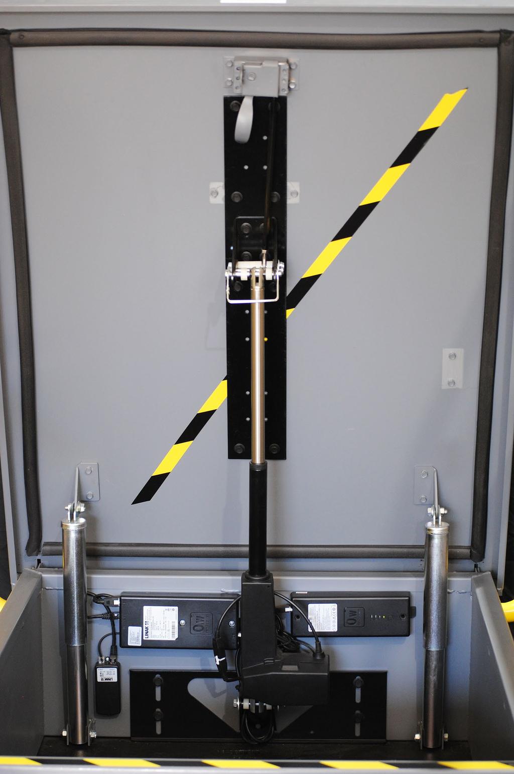
1 Automatic Roof Hatch Opener Installation Guide


")


2 REQUIRED TOOLS (These tools are required to complete the installation) Cordless Drill 1/8 1/4 Drill Bits 1/8 Pin Punch #2 Philips Bit Rachet Sharpie Hammer SAE Wrench Set Tape Measure RECOMMENDED (These tools will make your installation easier and quicker) SAE Socket Set Automatic Punch 5/16-18 Tap Ratcheting Wrench Set


")


3 ELECTRONIC PARTS Controller 110V Power Cord Battery Cable (If you ordered a 110V unit, 1 cable is included. With optional battery backup or Solar Powered unit, 2 are included) Actuator Actuator Cable Wireless Receiver & Remote Indoor Keypad Keypad Box Keypad Cable Data Cable(2)
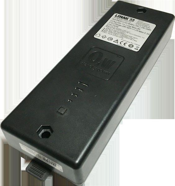


4 ACCESSORIES 24V DC Battery 24V DC Solar Panel Solar Panel Plug Outdoor Keypad Solar Panel & Outdoor Keypad Bracket


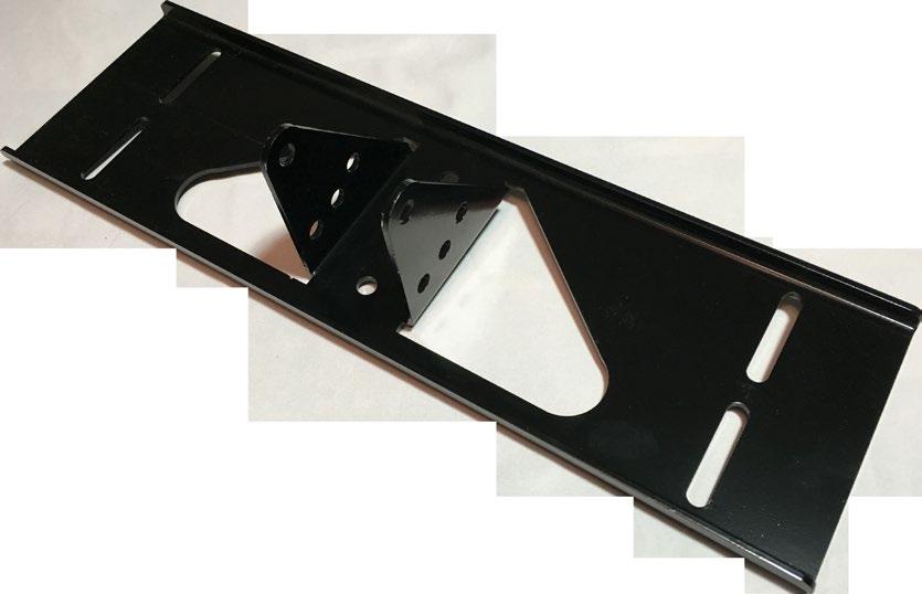


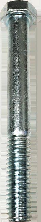

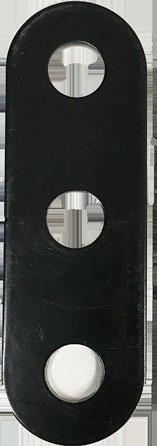

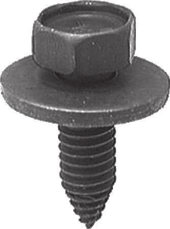

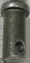


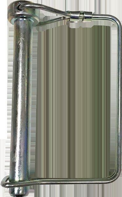


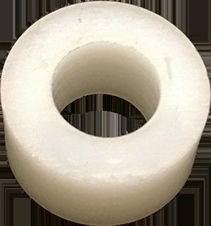

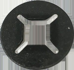


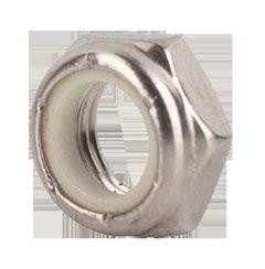

5 HARDWARE PARTS Rocker Bracket(1) Back Bracket(1) Nylon Spacer(9) Door Plate(1) 3 Hole Plate(2) Latch Bracket(1) 3/ Bolt(4) Thin Locknut(4) 5/16-18 Body Bolt(18) Cotter Pin(1) Push-on Locknut(1) Washer(8) Clevis Pin(1) Turnbuckle(1) #10 x 2 Self Drilling Screw(4) #6 x 3/4 Self Drilling Screw(4) 3 Locking Pin(1)


6 INSTALLATION STEP 1 DOOR PLATE 1. Find the center point of your latch and mark a vertical line just below it. If there is a handle below the latch, you will need to remove it. 3. Re-drill the existing holes with your 1/4 drill bit, or if you have a 5/16 18 tap, use the bit that came with your 5/16-18 tap. 2. Line your door plate with the center mark under the latch, and hold it about 1/4 below the latch. Mark the 8 outer holes with a sharpie. If you have a punch, punch the 8 marks in the center. Pre-drill the marks with the 1/8 drill bit making sure you stay centered in the marks. 4. Mount door plate with the included 5/16-18 body bolts. If you tapped the holes, you can start them with your hand. If not, you will need to use a drill and a 1/2 socket to get the bolts in place. Do not over-tighten the bolts. It is always a good practice to tighten by hand. 5. Next you will drill the holes for the rocker bracket. The location is determined by the size of the hatch lid from the hinge side to the latch side. The illustration to the left shows which set of holes to use for each lid size. Once the correct hole set is determined, drill/tap the holes the same as the other 8 door plate hole you previously drilled.


7 INSTALLATION STEP 2 ROCKER BRACKET & TURNBUCKLE Latch Bracket The following installation instructions are for latches of the same type as pictured to the right. For additional latch types, see the next page. Washer Clevis Pin 1. Remove the latch assembly. Cotter Pin Turnbuckle 2. Prepare turnbuckle/latch bracket assembly. Use needle nose pliers to bend cotter pin around the clevis pin. 3. Slide square hole over the latch rod like above with the clevis pin flat side facing the hatch lid. 6. Using a 3/8 x 3 bolt, 2 washers and the lock nut, install the two 3 Hole Plates by inserting the bolt through the center holes of the rocker bracket, and the center holes of the two 3 Hole Plates, with the Plates located between the rocker bracket ears as seen above. 4. Re-Install the latch assembly making sure the latch bracket is pointed to the right side. You should now be able to pull down on the turnbuckle and move the latch tongue. 5. Install Rocker Bracket, flat side down, using four 5/16-18 body bolts in the four holes previously drilled. Be sure you are using the correct holes according to your lid size(length). 7. Connect the Turnbuckle to the Rocker Bracket using a 3/8 x 3 bolt, 2 washers, lock nut, and 5 nylon spacers. There should be 4 spacers to the left, and one to the right of the turnbuckle as seen to the left. The washers are on the outsides of the Rocker Bracket. The bolt should be just tight enought that the washers can still move freely.


8 ALTERNATE LATCH TYPES Different roof hatch manufacturers use different latches. Below are 2 more examples of latches you may encounter in the field. While removing the handle, make sure the hatch lid is open. Using your 1/8 punch and hammer, knock out the retaining pin located at the base of the handle shaft. Once the pin has been removed you can pull the handle off of the hatch. Continue to remove the entire latch assembly. In order to gain access through the bottom of the latch, the bottom You can use an angle grinder to remove the bottom wall. If you do not have an angle grinder, you can use pliers to bend the wall up and down until it breaks off. This works just fine. With the latch type to the left, there is no need to remove the latch assembly. The handle rod protrudes from the assemble allowing you to use the included Latch Rod Lock Nut. Once your Turnbuckle Assembly is ready, slide the square hole of the Latch Bracket over the protruding rod. Press the Latch Rod Lock Nut onto the protruding rod. This will lock the Turnbuckle assembly in place. Once this is complete, you can move on.


9 INSTALLATION STEP 3(A) BACK BRACKET FLAT BACKED HATCHES 1. Line up the center of the back bracket with the center of the Door Plate. 2. Line up the bottom of the back bracket even with the bottom of the hatch. With the ears flat side up, mark the four outer holes at the center of the slots. Do not mark the center holes at this time. With your 1/4 drill bit, drill the four outer holes. If you have the 5/16-18 tap, use the drill bit that was included with the tap, then tap the holes. Insert the four 5/16-18 body bolts into the drilled/tapped holes and do not tighten all the way at this time. This is to allow proper adjustment of the bracket at a later time. This will be shown later in this guide. 3. When complete, it should like the above illustration, with the flat side of the ears facing up The two center holes will be used later, once the bracket is properly adjusted, to lock the bracket in place. Once you have the four outer bolts in, line up the bottom of the bracket with the bottom of the hatch, and hand tighten the four bolts. This will allow you to test the placement with the Actuator attached, without the bracket moving.


10 INSTALLATION STEP 3(B) BACK BRACKET SHELF BACKED HATCHES Some Hatches are not flat across the back wall. With hatches like this, you must install the provided Extender Kit. The Extender Kit consists of (2)4 hole plates, (4) 3/8-16 x 1/2 Round Head Slotted bolts, and (4)3/8-16 Nuts. Following the same angle as the ears of the Back Bracket, install the 4 Hole Plates as seen above. You should have one hole protruding from the end of the Back Bracket ears. Line up the bottom of the back bracket even with the bottom of the hatch. With the ears flat side down, mark the four outer holes at the center of the slots. Do not mark the center holes at this time. With your 1/4 drill bit, drill the four outer holes. If you have the 5/16-18 tap, use the drill bit that was included with the tap, then tap the holes. Insert the four 5/16-18 body bolts into the drilled/tapped holes and do not tighten all the way at this time. This is to allow proper adjustment of the bracket at a later time. This will be shown later in this guide.


11 INSTALLATION STEP 4 ELECTRONICS 1. Plug the Actuator Cable into the port labled 1 and route the cable through the channel on the back side of the controller. Plug the AC Power Cable into the port lableled AC (solar powered units will not have an AC cable). Route the cable through the strain relief channel on the back of the Controller. Be sure they stay in place as you mount the Controller. 2. Position Controller with right edge even with the left side of the bottom bracket ear as shown above. Use the 2 included #10 x 2 self drilling screws to attach the Controller. DO NOT OVERTIGHTEN. 3. Position the battery bracket about 4 below the top edge of the hatch. With the release tab on the right side, line up the right notch on the bracket with the right side of the back bracket as shown above. Use two of the included #6 x 3/4 self drilling screws to securely mount the battery bracket. 4. With the battery bracket installed, put the battery onto the bracket and slide it to the right to lock into place. This easy slide and lock battery makes replacing the battery a simple procedure in the future. 5. Position Keypad Box Under the right side of the controller You will mount it vertically, with the top hole centered in the upper left corner of the cut out in the back bracket. You will Use the included #10 x 2 self drilling screws to mount. Do Not Tighten the mounting screw at this time. Leave loose for adjustment.


12 INSTALLATION STEP 5 ELECTRICAL CONNECTIONS 1. Position Wireless Receiver on the left side of the back bracket, even with the top of the bracket as shown above. Use the two #6 x 3/4 self drilling screws to securely mount the receiver. Keypad Box Data Connector (Either connector is OK to use) (2) 18 Data Cables 2. Using the provided Data Cables, plug the first one in to the Controller Data Jack labled A1. Connect the other end to the left jack on the Wireless Receiver. Connect the other cable from the right jack on the Wireless Receiver to one of the Data jacks on the Keypad Box. Either jack is ok to use. Connection should look like above picture. 3. Using the two provided power cables, connect the first one from the Controller DC port labeled DC to the one of the power ports on the Keypad Box. Connect the second power cable from the other power port on the Keypad Box to the Battery DC port labled +/-. If you do not have a battery, you will only have one power cable.
 Set Keypad into programming mode with Factory set Master Code - 1 2 3 4 1 2 3 4 * * ---- 2 beeps, Keypad is in program mode.")

13 INSTALLATION STEP 6(A) INDOOR KEYPAD The Indoor Keypad can be programmed to the users preffered access code as seen below: PROGRAMMING NOTE: Wait 1 minute after power-up cycle, for beeping to stop. 1) Set Keypad into programming mode with Factory set Master Code * * beeps, Keypad is in program mode. 2) Change the Factory Master Code to Owners Master Code Note: Master Code is for programming only (your 4 digit pin) - # You will hear 2 beeps to confirm entry Plug the provided Data Cable from the Data Connector on the right side of the Keypad Box to the bottom of the Keypad. The Keypad will beep for one minute after power is applied. This is normal. The Keypad comes pre-programmed with an access code of 0000#. In order to re-program the Keypad follow the Programming Instructions to the right. The Keypad will need to be mounted. Depending on the location, you will need some type of drywall anchors, concrete anchors, and the associated screws. Use a #8 or #6 screw for mounting. 2 concrete anchors and #8 screws are included in the hardware kit. 3) Set User Pin to operate Output / Hatch Open Command (your 4 digit pin) - # You will hear 2 beeps to confirm entry Note: is for user number 2. Up to 999 user pins can be stored in Keypad. 4) Exit Programming Mode * * You will hear 2 beeps to confirm entry 5) To Operate Hatch (your 4 digit pin) # --- Up/Down Active for 30 seconds. Press and HOLD the UP or Down button to open or close the hatch.
 Set Keypad into programming mode with the Factory set Master Code - 1 2 3 4 1 2 3 4 * * ---- 2 beeps, Keypad is in program mode.")
 Change the Factory Master Code to Owners Master Code Note: Master Code is for programming only 0 1 -")

14 INSTALLATION STEP 6(B) OUTDOOR KEYPAD The Outdoor Keypad can be programmed to the users preffered access code as seen below: PROGRAMMING NOTE: Wait 1 minute after power-up cycle, for beeping to stop. 1) Set Keypad into programming mode with the Factory set Master Code * * beeps, Keypad is in program mode. Inside the Outdoor Weatherproof Keypad, you will find the same RJ12 connector inside. It is pre-wired for a quick plug and go install. Once keypad is mounted on rail with provided Keypad Bracket, route wire through the railing 2) Change the Factory Master Code to Owners Master Code Note: Master Code is for programming only (your 4 digit pin) - # You will hear 2 beeps to confirm entry 3) Set User Pin to operate Output / Door Open Command (your 4 digit pin) 1 - # Note: Your 4 digit pin is your code. The following 1 is for the Open Command is for user number 2. Up to 999 user pins can be stored in the Keypad. The Outdoor Keypad is installed using the provided mounting bracket, 2 3/8 x 1/2 Cap Screws and nuts, and 2 #14 x 3/4 Tek Screws. When attaching the keypad to the bracket, be sure the cap screw heads are inside the keypad housing. The 2 Tek screws are used to attach the bracket to the railing. Normal positioning would the the back end, left or right side of the railing. 4) Set User Pin to operate Output / Door Close Command (your 4 digit pin) 3 - # Note: Your 4 digit pin is your code. The following 3 is for the Close Command. 5) Exit Programming Mode * * ---2 beeps 6) To Operate Door (your 4 digit pin) 1 # (your 4 digit pin) 3 # ---Door Opens ---Door Closes


15 INSTALLATION STEP 7(IF PURCHASED) SOLAR PANEL If you purchased a solar powered unit you will need to mount the solar panel on the railing at a position with the panel facing due south. If you do not have our railing, a single solar panel post is available. The solar panel can be mounted as seen to the left, or inverted on any side of the back legs of the railing. The solar panel is mounted using the included #14 Tek Screws, (2) 3/8 x1/2 Bolts and Nuts, and the included Solar Panel Bracket. Drill a 1/4 hole in the railing for the Solar Panel Wire to go through. Route the wire through the rail and out of the foot. You will have to take off the rail end cap and drill a 1/4 hole in it as well. Route the wire over the back of the hatch wall. Included in the hardware bag is a DC plug with 2 terminals labeled + and -. The red wire from the Solar Panel will go into the + terminal, the Black into the - terminal. Plug the DC connector into the DC jack located on the Keypad Box.


16 INSTALLATION STEP 8 ACTUATOR 1. Using the included 3/8 x 3 Locking Pin, and 2 nylon spacers, connect the actuator to the rocker bracket as shown above, with 1 nylon spacer on each side of the actuator rod. 2. Using the included 3/8 x 3 Bolt, 2 washers, nylon lock nut, and 2 nylon spacers, connect the bottom of the actuator with the motor facing to the right as shown above. 1 nylon spacer on each side of the actuator. 3. Now that the Actuator is in place, plug in the end of the Actuator Cable to the pig-tail coming out of the Actuator. VERY IMPORTANT!!!! Once the Actuator is installed, the first thing you must do is remove the hatch lid holding arm. If you attempt to operate the Hatch Opener with the arm in place, damage will occur to the hatch itself, or the Automatic Roof Hatch Opener.


17 ADJUSTMENTS Center the Rocker Bracket so that the Bolts are in the middle of the Slide Cutouts, and tighten the 4 bolts to secure it in place. Tighten the Turnbuckle to remove the slack. It is a good idea to tighten is so that when you pull the hatch lid towards you, the tongue of the latch pulls in enough that is is even with the top of the latch body. This will prevent the hatch lid from binding upon first operation. Now that everything is in place and all the electronics are connected, it is time to make your adjustments and test the system. The first time you operate the Automatic Roof Hatch Opener, you will need to tighten the Rocker Bracket and the Back Bracket. Pulled Towards You Pushed Away From You Align the bottom of the Back Bracket with the bottom of the hatch, and tighten the 4 outer bolts. Use your 1/2 socket and ratchet to tighten. (CAUTION!! DO NOT OVER- TIGHTEN. You must be especially careful on aluminum hatches, as they will strip out easier than steel hatches if you over tighten the bolts.)

 you must continue the cycle in that direction. The system must see the limit switch in that direction to enable proper operation. 2(a).")
.")

18 ADJUSTMENTS 2(a). If the hatch lid does not close all the way, you will need to adjust the rocker bracket and move it up. 1. Upon first operation, it is a good idea to watch the lid from the inside so you can see how much travel the Actuator has left. If the lid still has a gap when the actuator is fully retracted, you will need to adjust the rocker bracket first. Use the included Wireless Remote to operate the hatch. NOTE: If the Actuator only moves one way(up/down) you must continue the cycle in that direction. The system must see the limit switch in that direction to enable proper operation. 2(a). Loosen the four bolts holding the Rocker Bracket and slide it up. Moving the Rocker Bracket up will cause the hatch lid to close more. Once it is adjusted, re-tighten the 4 bolts to secure the Rocker Bracket in place. 2(b). If the hatch lid closes all the way, and the actuator is not fully retracted, you will need to adjust the Rocker Bracket and move it down. When making adjustments to the Rocker Bracket, the latch position will change. Be sure after adjusting the Rocker Bracket, you re-adust the Turnbuckle to ensure the latch tongue retracts completely when pulling the hatch lid towards you. Final Turnbuckle adjustments will be made once the Rocker Bracket and Back Bracket adjustments are complete. 2(b). Loosen the four bolts holding the Rocker Bracket and slide it down. Moving the Rocker Bracket down will cause the hatch lid to close less. Once it is adjusted, re-tighten the 4 bolts to secure the Rocker Bracket in place.
19 ADJUSTMENTS If after adjusting the Rocker Bracket the hatch lid still does not close all the way, or still closes too much, you will need to adjust the Back Bracket. Return the Rocker Bracket to it s original position, with the bolts centered in the slots. Tighten the 4 bolts. Make sure the Turnbucle is adjusted so the latch tongue is flush with the top of the latch body when pulling the hatch lid towards you. Loosen the 4 outer bolts on the Back Bracket. Moving the Back Bracket UP will cause the hatch lid to close less, or create more gap. Moving the Back Bracket DOWN will cause the hatch lid to close more, or eliminate the gap. Move the Back Bracket up/down 1/2, tighten the 4 bolts, and operate the hatch to test the position. Once you have moved the Back Bracket up/down 1/2 and tightened the bolts, operate the hatch with the remote again. If you still have a small gap, or it is still closing too much you can now adjust the Rocker Bracket UP/DOWN again to get the hatch lid where it needs to be. Alternate between the Back Bracket, and the Rocker Bracket for proper adjustment of the hatch lid. When the hatch lid is properly adjusted, you should not see any light entering through the hatch seal. Once it is at this point, you can now put the 2 center bolts in the Back Bracket. You will have to remove the bottom Actuator bolt to do this. Be careful when removing the bolt, as the lid is now free, and can close without warning. Once the 2 center bolts are in place, you can now re-connect the Actuator and move on to adjusting the turnbuckle.


20 TURNBUCKLE ADJUSTMENTS Loosen the Turnbuckle to allow the latch tongue to stick out about 1/4. Lightly pull on the hatch lid and make sure the latch tongue retracts, and then push the lid away from you and make sure the latch tongue extends. Once you are certain that the latch tongue moves freely, you can now operate the Automatic Roof Hatch Opener. From inside the hatch, use the remote and close the hatch lid. When it closes all the way you should hear the latch tongue click if it catches. If you do not hear a click, look at the tongue and verify that the hatch is closing enough for it to latch. If the tongue is not sticking out far enough to catch, loosen the Turnbuckle more to extend the latch tongue more. When opening the hatch lid, the Actuator will begin to extend and then it will pull the Turnbuckle to release the latch. If upon opening the lid, the latch does not release, tighten the Turnbuckle to retract the latch tongue more. Try to open it again. Repeat this process until the Turnbuckle is properly adjusted. The hatch lid will pop when you open it because the springs are also putting pressure on it. This is normal and happens on every hatch. Twisting the Turnbuckle in this direction will increase the overall length, making the latch tongue stick out further. Twisting the Turnbuckle in this direction will decrease the overall length, making the latch tongue stick out less.


21 COMPLETION Now that everthing is properly adjusted, you need to go back through and tighten all the nuts/bolts. Make sure the 4 Rocker Bracket body bolts are tight. Check the two 3 bolts. They should be tightened to the point where there is no gap, but the washers can still move freely. This will ensure smooth operation of the turnbuckle assembly. If these 2 bolts are too tight, the turnbuckle will not move. Tighten the bottom 3 bolt tightly. This bolt can be tightened enough that the bolt and the washers do not move. Check the 6 body bolts on the back plate and make sure they are all hand tight. Be sure not to overtighten these bolts, as they can strip easily on certain hatch types. Check the locking nut on the turnbuckle. This nut should be tightened securely against the black hex-rod to keep the turnbuckle adjustment in place. If this is not tightened, the turnbuckle can move during use. If this happens, the tongue will not release, causing the hatch to bind when opening. INSTALL COMPLETE!!


22 TROUBLESHOOTING The hatch will only move up/down. Upon first operation the hatch may only move one way. Continue moving the hatch that way to complete the cycle. The Controller needs to see the limit switch in order to complete the cycle. Once the Actuator completes the cycle, you will be able to operate the hatch in the opposite direction. The hatch doesnt move at all. If you get no movement at all, first check all of your electrical connections. Make sure the plugs are securely snapped in correctly, and make sure the actuator and data cable are inserted into the correct ports. If it is a solar powered unit, press the battery status button located on the front of the battery. This will show you the charge level of the battery. If the battery is too low, you will not see any bars light up. In this case, the battery must charge before the hatch will operate properly. If you have a 110V unit, make sure there is power at the plug. The hatch only works with the remote or keypad. If the hatch will operate with the keypad only, the remote might need to be synced with the wireless receiver. To do this, see the next page. If the hatch only operates with the remote, check the connections on the keypad. If you have power on the keypad, and you see a green light when you enter your code, you may need to open the keypad up and make sure there are no loose wires.
23 MAINTAINENCE The SafePro Automatic Roof Hatch Opener requires very little maintainence. Follow the schedule below to ensure problem free operation of your new A.R.H.O. MONTHLY 1. Do a physical inspection on the entire ARHO system. Make sure all parts are moving freely. Make sure the latch release properly and does not contrain the opening of the hatch. Look for any loose wires that may be snagged while operating the hatch, or entering/exiting the hatch. 1. If you have a solar powered unit, check the solar panel to make sure the glass is not broken, and that it is clean of dirt and debris. This will ensure maximum charging for your battery. SEMI-ANNUALY 1. Check the charging status of your batteryby pressing the status indicator button located on the front of the battery. If you notice that it is only charging to 75% or less, your battery is not operating at maximum capacity and needs replacement soon. A replacement battery is available from SafePro. 2. Check/Grease the rocker bracket and latch with a spray lithium grease, or silicone based spray. This will ensure smooth opening/closing of the hatch. 3. Make sure the Turnbuckle lock nut is securely against the Turnbuckle Rod. If the locknut moves, the Turnbuckle can re-adjust itself and cause the latch to not release. This can cause the hatch to bind causing damage to the ARHO system, or the roof hatch.
Technical Support (707)
") Installation Instructions UNIMATIC SHIFTER Fits: GM, Powerglide, Ford and Chrysler Transmissions See Application Guide for Specific Vehicles Catalog # 80775 WORK SAFELY! For maximum safety, perform this
Installation Instructions UNIMATIC SHIFTER Fits: GM, Powerglide, Ford and Chrysler Transmissions See Application Guide for Specific Vehicles Catalog # 80775 WORK SAFELY! For maximum safety, perform this
Installation Instructions Unimatic Shifter
 Installation Instructions Unimatic Shifter Universal Shifter for Automatic Transmissions Part Number 80775 2000 by B&M Racing & Performance Products LLC The B&M Unimatic is a universal shifter that will
Installation Instructions Unimatic Shifter
 Installation Instructions Unimatic Shifter Universal Shifter for Automatic Transmissions Part Number 80775 2010, 2000 by B&M Racing & Performance Products The B&M Unimatic is a universal shifter that will
Installation Instructions Z-Gate Shifter
 Installation Instructions Z-Gate Shifter Part Number 80681 1998, 2001 by B&M Racing and Performance Products The B&M Z-Gate shifter can be used in vehicles equipped with most popular three speed automatic
Technical Support (707)
") Installation Instructions CONSOLE MEGASHIFTER Fits: 1982-1992 Camaro & Firebird w/automatic Transmission *except 1988-1992 Firebird Formula Model Catalog # 80692 WORK SAFELY! For maximum safety, perform
Installation Instructions CONSOLE MEGASHIFTER Fits: 1982-1992 Camaro & Firebird w/automatic Transmission *except 1988-1992 Firebird Formula Model Catalog # 80692 WORK SAFELY! For maximum safety, perform
Factory Five Racing, Inc. 818 Kit Assembly manual revision 1J update
 Factory Five Racing, Inc. 818 Kit Assembly manual revision 1J update Turbo coolant overflow tank...1 Shifter handle...4 Install...4 Door skin...7 Door Liner... 10 Side mirrors... 14 Door handles and pulls...
Installation Instructions Sport Shifter
 The B&M Sport Shifter can be used in vehicles equipped with most popular three speed or four speed automatic transmissions. It is equipped with neutral safety and backup light switches, transmission brackets
Sunroof Repair. Sunroof Repair TSB. The sunroof repair kit available for the J30 is part number Y20. See images at bottom of document.
 Sunroof Repair This document is the text/images from the TSB (technical service bulletin) issued by Infiniti concerning the repair procedure for sunroof issues. Be advised that this is a LARGE, TIME-CONSUMING
Z-Gate Universal Shifter
 Installation Instructions Z-Gate Universal Shifter Fits: GM, Ford, Lincoln and Chrysler Transmissions See Application Guide for Specific Applications Part #80681 Rev 06/01/2018 WORK SAFELY! For maximum
Installation Instructions. QuickSilver Shifter. Fits: GM, Ford, Chrysler Transmissions See Application Guide for Specific Applications Part # 80683
 Installation Instructions QuickSilver Shifter Fits: GM, Ford, Chrysler Transmissions See Application Guide for Specific Applications Part # 80683 WORK SAFELY! For maximum safety, perform this installation
RS-2 SINGLE ACTION REAR BUMPER WITH TIRE CARRIER INSTALL MANUAL FOR JEEP WRANGLER ALL MODELS.
 RS-2 SINGLE ACTION REAR BUMPER WITH TIRE CARRIER INSTALL MANUAL FOR 2007-2016 JEEP WRANGLER ALL MODELS. Rear Bumper Installation Instructions 1) Remove factory rear bumper, (this includes all tow hitch
Throttle Cable Pull - Patent Pending By: NetGain Controls, Inc.
 Throttle Cable Pull - Patent Pending By: NetGain Controls, Inc. Powering the future! Installation Guide 2011 All Rights Reserved NetGain Controls, Inc. 1 of 8 Introduction Thank you for purchasing a NetGain
INSTALLATION & OWNER S MANUAL
 Rev. B, p. 1 of 25 INSTALLATION & OWNER S MANUAL POLARIS RANGER RCS (for models XP or HD) (for model years 2009-) cab without doors kit (p/n 1POLRCWD) cab with doors kit (p/n 1POLRC) doors only kit (p/n
Installation Instructions QUICKSILVER CONSOLE SHIFTER Fits: Chevelle / El Camino
 WORK SAFELY! For maximum safety, perform this installation on a clean, level surface and with the engine turned off. Place blocks or wedges in front of and behind both rear wheels to prevent movement in
Toyota Prius Dual Player Headrest Video ATTENTION: SECURITY COVERS ARE NO LONGER INCLUDED IN THE HEADREST KITS AS OF 01/17/2011
 Toyota Prius 2011 - Dual Player Headrest Video Part Number: 00016-47210-01; 04; 11 Code : EH5 ATTENTION: SECURITY COVERS ARE NO LONGER INCLUDED IN THE HEADREST KITS AS OF 01/17/2011 Conflicts Kit Contents
FOR New Electric Kit and Remote Control Installation
 Installation Manual COMMAND-10 REMOTE AND COMMAND STATION FOR New Electric Kit and Remote Control Installation Use these in place of the rocker switch and solenoid section of instructions in your roll
H15P. Toyota Hilux A-DECK Dual Cab
 Toyota Hilux A-DECK Dual Cab Page 1 of 14 Fitting Instructions Part Number H15 Toyota Hilux A-DECK Dual Cab 2015+ To suit Sports Bars Check contents of kit before commencing fitment and report any discrepancies
UNPACK AND IDENTIFY THE FOLLOWING PARTS.
 SUT-250-M2 ASSEMBLY REQUIREMENTS *Torque all T-bolt nuts to 35-40 foot pounds. *Check all lights before towing. *Tire pressure not to exceed recommendation on serial tag. *Re-torque wheel nuts after first
2. With the rear door open remove pull-style clip from the passenger side just below the door latch.
 LoD Offroad FJ Cruiser Rear Bumper with Tire Carrier Installation Instructions 1. Begin with removing factory spare from the rear door. 2. With the rear door open remove pull-style clip from the passenger
Performance Air Intake, 2015+
 PARTS LIST AND PARTS LIST 1PC ALUMINUM INTAKE PIPE 1PC HIGH-FLOW, OILED AIR FILTER 1PC SILICONE INDUCTION HOSE 1PC AIRBOX 1PC 1/16 RUBBER STRIPPING, 9 LENGTH 1PC 1/16 RUBBER STRIPPING, 8.5 LENGTH 1PC WORM-GEAR
Installation Instructions Pro Stick Shifter
 Installation Instructions Pro Stick Shifter Part Number 80701, 80702 & 80706 2012, 2010, 2008, 2001, 1998 by B&M Racing and Performance Products The B&M Pro Stick shifter #80701 and #80706 comes equipped
JEEP JK4 STEP SLIDER INSTALLATION BD-SS-100-JK4
 JEEP JK4 STEP SLIDER INSTALLATION BD-SS-100-JK4 PARTS LIST QTY DESCRIPTION 1 Drivers Side Slider Assembly 1 Passenger Side Slider Assembly 1 Wiring Harness and Fuse 1 Double Sided Sticky Squares and Alcohol
C15C C15C. Page 1 of 20
 2 x Lid Front Hinge 1135 8 x M8 Bolt 8 x M8 Washer (3mm Thick) 4 x M6 Large washers 4 x M6 Spring washers 4 x M6 x 40mm Bolts 6 x M6 20mm Bolts 6 x M6 Washers 20 x Screws 2 x Lid mount gas strut bracket
McDonalds Installation Guide
 McDonalds Installation Guide Canopy COD Installation CCOD ------------------------------------------------------------------------------------------------------ Metal Pedestal COD Installation MCOD Everbrite
Assembly Manual. Assembly Instructions Read Carefully 2.1. Parts included: Tools suggested: Electric Drill
 2.1 Assembly Manual Tools suggested: Parts included: Electric Drill 3/8ths bit 5/16ths bit Phillips screw driver Cutting pliers 1/2 inch socket wrench 1/2 inch wrench or crescent wrench 8 mm socket wrench
Bag 1. Bag 1. Center Pivot. Center Pivot
 8 00734 01901 5 Center Pivot Bag 1 3374 - Center Pivot Socket 4019 - Alum Pivot ball 3254-2-56 Button Head *Note - Sometimes it is helpful to slightly over-tighten the top clamp screws, then work the ball
Installation Instructions Table of Contents
 Installation Instructions Table of Contents Pre- Installation of Garage Storage Lift 2 Layout the Garage Storage Lift 3 Installing the strut Channels 3 Install the Drive Assembly 5 Install the Drive Shaft
Installation Instructions Console Megashifter
 Installation Instructions Console Megashifter 1968-1969 Camaro Part Number 81035 This B&M Megashifter is designed to fit in the console of a 1968-1969 Chevrolet Camaro. In 1968, these vehicles were equipped
Here we have the old lock on an exterior door (note more than one door was used for this article- taking the best pictures of the group)
") Alarm lock T2 Part 1 of 4 Installations Eugene Hansen 2004 This is the first part of four, 1st we will install a T2 Trilogy, 2 nd replacing the batteries, 3 rd replacing the solenoid and finally 4 th reprogramming
Alarm lock T2 Part 1 of 4 Installations Eugene Hansen 2004 This is the first part of four, 1st we will install a T2 Trilogy, 2 nd replacing the batteries, 3 rd replacing the solenoid and finally 4 th reprogramming
Training Documentation
 Training Documentation Manual Shades There are two styles of adjustment wheels for Manual Shades: External Adjuster No tools needed. Wheel is turned by hand. Slot Adjuster (Accessed thru bracket end) Flat
Light Truck MegaShifter
 Installation Instructions Light Truck MegaShifter The B&M Light Truck Megashifter shifter is designed to be used in most light trucks equipped with most popular three speed or four speed automatic transmissions.
INSTALLATION MANUAL. Thunderstone Manufacturing LLC 3400 West O Street Lincoln, NE (Fax)
") INSTALLATION MANUAL August 7 th 2018 43 /48 /50 2011 and Older Timpte STD/Split 36 Style Hopper Trailers with Roller Bearing Doors Kit #101533 for 96w & Kit #101534 for 102w Thunderstone Manufacturing
INSTALLATION MANUAL August 7 th 2018 43 /48 /50 2011 and Older Timpte STD/Split 36 Style Hopper Trailers with Roller Bearing Doors Kit #101533 for 96w & Kit #101534 for 102w Thunderstone Manufacturing
CALIFORNIA TRIMMER MOWER MAINTENANCE MANUAL
 CALIFORNIA TRIMMER MOWER MAINTENANCE MANUAL 2 Table of Contents Section 1: General Information Page Handle Assembly Instructions 4 Maintenance All Models 6 Oil Change Procedures All Models 9 Height Adjustment
MATCHLESS SPINNING WHEEL
 MATCHLESS SPINNING WHEEL Single Treadle to Double Treadle Conversion Instructions Find out more at schachtspindle.com Schacht Spindle Company 6101 Ben Place Boulder, CO 80301 p. 303.442.3212 f. 303.447.9273
Detroit Speed, Inc. Electric Headlight Door Kit Corvette P/N: &
 Detroit Speed, Inc. Electric Headlight Door Kit 1968-82 Corvette P/N: 122006 & 122007 The Detroit Speed Inc. Electric Headlight Door Kit replaces the stock vacuum actuated system on all 1968-82 Corvettes.
Safety First. Please remember to always use SAFE shop practices when performing all service procedures.
 Safety First Please remember to always use SAFE shop practices when performing all service procedures. 2006 Update Manual January 2006 Country Clipper 2006 Update Manual Index Joystick Kill Switch Oil
Q15P. Mitsubishi MQ Triton Dual Cab
 Mitsubishi MQ Triton Dual Cab Page 1 of 12 Fitting Instructions Part Number Mitsubishi MQ Triton Dual Cab 2015+ To suit Sports Bars Check contents of kit before commencing fitment and report any discrepancies
Assembly Manual. 1/10th Formula 1 Car
 Assembly Manual 1/10th Formula 1 Car Center Pivot Bag 1 3374 - Center Pivot Socket 40194 - Hard Anodized Alum Pivot ball 3254-2-56 *Note - Sometimes it is helpful to slightly over-tighten the top clamp
HiBoy Maverick/Commander Doors Part # HiBoy4 Maverick/Commander Doors Black
 Racing 3191 N Washington St. Suite 2 Chandler, AZ 85225 1 (800) 708-9803 http://www.racing.com HiBoy Maverick/Commander Doors Part # 07-2001 HiBoy4 Maverick/Commander Doors Black Congratulations on your
Deuce/Ace Installation Instructions
 HARDWARE KIT: Upper Mounting Plate: 2-7/16" (11mm) X 3.5" bolts 2-7/16" flange nuts 2-2" spacers 2-7/16" trim cap mounting washers 2 - plastic trim caps TOOLS NEEDED: safety glasses wrenches 16mm or 5/8"
INSTALLATION & OWNER S MANUAL
 Pg. 1 of 14 INSTALLATION & OWNER S MANUAL John Deere Gator XUV 825i S4 Cab (p/n: 1GTRXUV4 Steel Cab with Doors) The contents of this envelope are the property of the owner. Be sure to leave with the owner
USER'S MANUAL and INSTALLATION GUIDE
 AM Inlet Series 8" and 2" baffle AM0896GS AM296GS USER'S MANUAL and INSTALLATION GUIDE TABLE OF CONTENTS Section Page...Requirements for Installation...2 2...Unpacking the AirManager... 3-5...Exploded
PD10-M-RIM INSTALLATION INSTRUCTIONS. The PD10-M-RIM is a storefront grade 1 exit device equipped with motor drive latch retraction.
 PD10-M-RIM INSTALLATION INSTRUCTIONS The PD10-M-RIM is a storefront grade 1 exit device equipped with motor drive latch retraction. Retrofits Doromatic 1790 & First Choice 3790. B. G. A. C. D. E. F. PD10-M-RIM
<THESE INSTRUCTIONS MUST BE GIVEN TO THE END USER> B&W
 B&W Trailer Hitches 1216 Hawaii Rd / PO Box 186 Humboldt, KS 66748 Turnoverball Gooseneck Hitch Installation Instructions MODEL 1314 2013 2014 RAM 3500
WJ AUTO TRANS. ATLAS SHIFTER
 KIT CONSISTS OF: No. Qty Part No. Description 4320 Aerotech Center Way, Page 1 of 8 1 1 302051 BASE- ATLAS TWIN STICK MOUNT 2 1 302080 STUD BOLT 1/2-13 X 7 B7 3 1 303120 Serrated-Flange Hex Locknut 1/2-13
Universal Mounting Kit #0520
 Universal Mounting Kit #0520 #0503 SuperGlide (25.5K) #0515 SuperGlide Low Profile (25.5K) Gross Trailer Weight (Maximum) Vertical Load Weight (Max. Pin Weight) 25,500 lbs. 6,375 lbs. Gross Trailer Weight
EVO-1162 EVO Tailgate Tire Carrier
 EVO-1162 EVO Tailgate Tire Carrier Bill of Materials EVO-1162 Tailgate Tire Carrier Part number Description Quantity EVO-12161 EVO Tailgate Tire Carrier 1 EVO-12162 Bolt Plate 1 EVO-12163 Wheel Mount 1
INSTALLATION INSTRUCTIONS
 INSTALLATION INSTRUCTIONS FUEL SURGE TANK INSTALLATION KIT 1999-2006 BMW E46 COUPE Document# 19-0056 Support: info@radiumauto.com Note: This kit was designed for a standard single pump Radium Engineering
Installation Instructions Right Hand Drive Megashifter
 Installation Instructions Right Hand Drive Megashifter Part Number 80685 1995, 2001, 2006, 2010 by B&M Racing & Performance Products The B&M Right Hand Drive Megashifter is designed specifically for vehicles
Ram 1500 Crew Cab A Ram 2500/3500 Crew Cab A
 I N S T A L L A T I O N G U I D E APPLICATION AMP Part # Ram 1500 Crew Cab 2013-2015 77138-01A Ram 2500/3500 Crew Cab 2013-2015 77138-01A Note:The application works only on the Crew Cab model Vehicles.
Combine Cover Manual
 Combine Cover Manual Installation Instructions Page 27 Operating Instructions Page 8 Warranty Page 8 Trouble Shooting Page 9 11 For Model s: Case I.H. 2388, 2188, 1688 and 1680 With a MAURER Hopper Extension
RETRACTED SIDE MINIMUM. 4 1/4 in. [108.0 mm] CP-493 HANGER (WITHOUT TRIGGER) RETRACTED SIDE CP-007 CLIP ACTIVATED SIDE MINIMUM. [108.
![RETRACTED SIDE MINIMUM. 4 1/4 in. [108.0 mm] CP-493 HANGER (WITHOUT TRIGGER) RETRACTED SIDE CP-007 CLIP ACTIVATED SIDE MINIMUM. [108.](/thumbs/88/116251221.jpg "RETRACTED SIDE MINIMUM. 4 1/4 in. [108.0 mm] CP-493 HANGER (WITHOUT TRIGGER) RETRACTED SIDE CP-007 CLIP ACTIVATED SIDE MINIMUM. [108.") TYPE CC-NRB CATCH N CLOSE CROWDERFRAME POCKET DOOR KIT INSTRUCTION SHEET FOR NARROW DOORS 18 in [457 mm] TO LESS THAN 26 in [660 mm] WIDE ONLY ACTIVATED SIDE CC-493 HANGER (WITH TRIGGER) SEE RIGHT (COMPLETE
TYPE CC-NRB CATCH N CLOSE CROWDERFRAME POCKET DOOR KIT INSTRUCTION SHEET FOR NARROW DOORS 18 in [457 mm] TO LESS THAN 26 in [660 mm] WIDE ONLY ACTIVATED SIDE CC-493 HANGER (WITH TRIGGER) SEE RIGHT (COMPLETE
WARNING NOTICE CAUTION ASSEMBLY INSTRUCTIONS
 MODEL 284 EZ-GLIDE SYSTEM 10' HIGH CUBE VAN DRIVER SIDE ALUMINUM DROP DOWN LADDER RACK ATTENTION Read and understand all instructions and warnings before operating or using this product. WARNING This product
Hurst VMATIC3 INSTALLATION
 FORM 159 8530 07/12 Hurst VMATIC3 3-Speed & 4-Speed Automatic Shifter Catalog #3838530 2012 by Hurst Performance The Hurst Vmatic3 shifter can be used in vehicles equipped with most popular three speed
J & D Machine / Hyperdrive / MSA 3711 Moon Bend Rd. Chapel Hill, TN 37034
 J & D Machine / Hyperdrive / MSA 3711 Moon Bend Rd. Chapel Hill, TN 37034 www.hyperdriveracing.com 1 You now own a state of the art 1/10 scale oval race car. The Hyperdrive Assault has gone through months
JEEP Wrangler JK/JKU Swing-A-Way Tire Carrier/RotoPpax WARNINGS/CAUTIONS NOTE. INSTALLATION INSTRUCTIONS 2 Door Models 85209
 JEEP Wrangler JK/JKU Swing-A-Way Tire Carrier/RotoPpax 2007-2017 INSTALLATION INSTRUCTIONS Item Kit No. 2 Door Models 85209 4 Door Models 85209 WARNINGS/CAUTIONS These instructions are for both the can
INSTALLATION & OWNER S MANUAL
 Rev. C p. 1 of 21 INSTALLATION & OWNER S MANUAL F5205 HARD SIDED CAB KIT INSTALLATION & OWNER S MANUAL The contents of this envelope are the property of the owner. Be sure to leave with the owner when
Van Rack Installation Manual Ford Transit Connect
 1.888.772.8400 Big to small... We do it all Van Rack Installation Manual Ford Transit Connect Thank you for your purchase of an Unruh Fab Van rack. We have designed and built this rack so that you can
MNBRATKIT MidNite Brat Solar Charging Kit
 1 pc MNBRAT 20/30-amp PWM Charge Controller 1 pc MNBIGBABY Breaker Box 3 pcs 1-10A 1-20A 1-30A MNEPV- PV, Battery and Load Breakers 2 pcs 2 pcs 9-161-1 Strain Relief 9-162-1 Lock Nut 2-4 Hole Strain Reliefs
MAINTENANCE WEIGHT RATINGS WARNINGS. warning: never exceed your vehicle manufacturer's recommended towing capacity
 Installation instructions warning: never exceed your vehicle manufacturer's recommended towing capacity Round Bar WEIGHT DISTRIBUTION kit MAINTENANCE Keep the socket-mounted ends of the spring bars and
Installation Instructions COMPETITION/PLUS SHIFTER Ford Mustang MT82 6-Speed Manual Transmission Catalog#
 Installation Instructions COMPETITION/PLUS SHIFTER 2015-2017 Ford Mustang MT82 6-Speed Manual Transmission Catalog# 3916037 Rev. 00 WORK SAFELY! For maximum safety, perform this installation on a clean,
Installation Manual TWM Performance Short Shifter Cobalt SS/SC, SS/TC, HHR SS, Ion Redline and Saab 9-3
 Page 1 Installation Manual TWM Performance Short Shifter Cobalt SS/SC, SS/TC, HHR SS, Ion Redline and Saab 9-3 Please Note: It is preferable to park on a flat surface, as you will have to engage and disengage
2800 VIBRO-TILL FIELD CULTIVATOR ASSEMBLY INSTRUCTIONS Series. Kongskilde
 2800 VIBRO-TILL FIELD CULTIVATOR Kongskilde 2800 Series *Model may not be exactly as shown. Kongskilde reserves the right to make changes to product designs and specifications without notice or obligation
TYPE CC-W CATCH N CLOSE CROWDERFRAME POCKET DOOR KIT INSTRUCTION SHEET FOR DOORS 26 in [660 mm] TO 48 in [1219 mm] WIDE ONLY
![TYPE CC-W CATCH N CLOSE CROWDERFRAME POCKET DOOR KIT INSTRUCTION SHEET FOR DOORS 26 in [660 mm] TO 48 in [1219 mm] WIDE ONLY](/thumbs/93/113592678.jpg "TYPE CC-W CATCH N CLOSE CROWDERFRAME POCKET DOOR KIT INSTRUCTION SHEET FOR DOORS 26 in [660 mm] TO 48 in [1219 mm] WIDE ONLY") TYPE CC-W CATCH N CLOSE CROWDERFRAME POCKET DOOR KIT INSTRUCTION SHEET FOR DOORS 26 in [660 mm] TO 48 in [1219 mm] WIDE ONLY (COMPLETE TYPE CC-W KIT ILLUSTRATED. FRAMING BY OTHERS) CATCH N CLOSE TM CROWDERFRAME
TYPE CC-W CATCH N CLOSE CROWDERFRAME POCKET DOOR KIT INSTRUCTION SHEET FOR DOORS 26 in [660 mm] TO 48 in [1219 mm] WIDE ONLY (COMPLETE TYPE CC-W KIT ILLUSTRATED. FRAMING BY OTHERS) CATCH N CLOSE TM CROWDERFRAME
INSTALLATION INSTRUCTIONS RATTLER STEEL RUNNING BOARDS FORD TRANSIT VAN (FULL SIZE)
") INSTALLATION INSTRUCTIONS PARTS LIST: 1 32-inch Steel Running Board 1 8-1.25mm x 35mm Hex Bolt 1 96-inch Steel Running Board 13 8-1.25mm x 25mm Hex Bolt 5 Passenger Side/Driver Side Mounting Brackets 20
INSTALLATION INSTRUCTIONS PARTS LIST: 1 32-inch Steel Running Board 1 8-1.25mm x 35mm Hex Bolt 1 96-inch Steel Running Board 13 8-1.25mm x 25mm Hex Bolt 5 Passenger Side/Driver Side Mounting Brackets 20
Chain/Belt Drive Models PRE-INSTALLATION CONSIDERATIONS
 38968503545. 08/2017 ASSEMBLY/INSTALLATION Chain/Belt Drive Models PRE-INSTALLATION CONSIDERATIONS This opener includes parts and supplies needed for installation in most garages and on most garage doors.
Installation Guide CLAAS Lexion Combines with 9 inch Elevators
 Installation Guide CLAAS Lexion Combines with 9 inch Elevators 955614_01 4/17 1 Table of Contents System Overview 3 Quick Start Guide 4 Flow Sensor Installation 5 Hydraulic Elevator Adjustment Kit Installation
<THESE INSTRUCTIONS MUST BE GIVEN TO THE END USER> B&W
 B&W Trailer Hitches 1216 Hawaii Rd / PO Box 186 Humboldt, KS 66748 P:620.473.3664 F:620.869.9031 Turnoverball Gooseneck Hitch Installation Instructions
TCI FastGate Shifter Installation Instructions
 151 INDUSTRIAL DRIVE ASHLAND, MISSISSIPPI 38603 http://www.tciauto.com TELEPHONE: 662-224-8972 FAX LINE: 662-224-8255 E-MAIL: tech@tciauto.com TCI 616541 FastGate Shifter Installation Instructions The
Section 5: Parts Replacement
 Section 5: Parts Replacement Should the STAR TRAC 4500 Treadmill experience a problem requiring replacement of a specific part, the following procedures will help and instruct in the replacement of major
$1.00 FOR THE TQIO/RCIO
 $1.00 FOR THE TQIO/RCIO m mm HDBBYSHOP Champion Jay Halsey has an impressive track record. One of Jay's advantages is a whisper smooth tranny thanks to his dad, Jim. Now you can build a Halsey transmission!
Cold Air Intake Installation Instructions
 BAVARIAN AUTOSPORT Cold Air Intake Installation Instructions PARTS LIST: PF BMWE36-4 PROCEDURE: 1. Using a flat-head screwdriver, loosen the hose clamp between the AFM and rubber boot leading to engine
GM C10 Street Grip
 Part # 11365010/11365110-1973-1987 GM C10 StreetGrip Front Components 11369590 Delrin Control Arm Bushings 11369300 Drop Spindles 11362350/11362351 Front CoilSpring Kit 11369515 Front HQ Series Shocks
IMPORTANT! Remote Control Instructions
 Remote Control Instructions FOR New Tarp Remote Control Installation Use these in place of the rocker switch and solenoid section of instructions in your roll tarp owner s manual. FOR Existing Electric
Combine Cover Manual
 Combine Cover Manual Installation Instructions Page 26 Operating Instructions Page 7 Warranty Page 7 Trouble Shooting Page 8 10 For Big Top Extension Model s: Case I.H. 8010, 8120 Please forward onto Customer
Installation Instructions Megashifter
 Installation Instructions Megashifter The B&M Megashifter shifter can be used in vehicles equipped with most popular three speed or four speed automatic transmissions. Your B&M Megashifter comes equipped
Installation Manual TWM Performance Short Shifter Subaru STi 2008+
 - 1 - Installation Manual TWM Performance Short Shifter Subaru STi 2008+ Please Note: It is preferable to park on a flat surface, as you will have to engage and disengage the hand brake and shift from
RHINO SUSPENSION SYSTEM INSTALLATION INSTRUCTIONS
 PARTS INCLUDED: 2 FRONT UPPER A-ARMS 2 FRONT LOWER A-ARMS 2 UNI-BALL JOINTS 2 UNI-BALL JOINT STUDS 2 UNI-BALL JOINT CAPS 2 RETAINING RINGS 1 FRONT SHOCK ASSEM. 2 DELRON STEERING STOPS 2 SHOCK MOUNT SPACERS
INSTALLATION GUIDE. KTM 125, 144, Stroke KTM 250, Stroke KTM 250 SXF, XC, XC-W KTM 450, 505 SXF Manual Revision:
 REKLUSE MOTOR SPORTS The z-start Pro Clutch INSTALLATION GUIDE KTM 125, 144, 200 2-Stroke KTM 250, 300 2-Stroke KTM 250 SXF, XC, XC-W KTM 450, 505 SXF 191-836 Manual Revision: 050307 2002 Rekluse Motor
INSTALLATION INSTRUCTIONS
 INSTALLATION INSTRUCTIONS WARNING: NEVER EXCEED YOUR VEHICLE MANUFACTURER'S RECOMMENDED TOWING CAPACITY PIN-STYLE TRUNNION BAR WEIGHT DISTRIBUTION KIT MAINTENANCE Keep the socket-mounted ends of the spring
Chrysler A-Body Tubular A-Arms Installation Instructions A-ARM INSTALLATION
 1967-1976 Dodge Demon 1112 67-72 Chrysler A-Body Tubular A-Arms Installation Instructions Thank you for your purchase of this Hotchkis Performance product. Your A-Arm set was designed with the performance
I N S T A L L A T I O N G U I D E. Ram 1500 Crew Cab A Ram 2500/3500 Crew Cab A
 I N S T A L L A T I O N G U I D E APPLICATION AMP Part # Ram 1500 Crew Cab 2009-2012 77158-01A Ram 2500/3500 Crew Cab 2010-2012 77158-01A Note:The application works only on the Crew Cab model Vehicles.
INSTALLATION INSTRUCTIONS CHEVY C-10 4-Link Rear End
 INSTALLATION INSTRUCTIONS 73-87 CHEVY C-10 4-Link Rear End Please read these instructions completely before starting your installation. Assemble suspension on vehicle before powder-coating to ensure proper
55-64 Full Size Chevy
 55-64 Full Size Chevy Installation Instructions Power Disc Conversion 9 slimline booster pictured Your new disc brake conversion kit can be bolted up with standard hand tools. The only tools you may not
FRONT DRIVELINE MODIFICATION MAY BE NECESSARY!!!!
 INSTALLATION INSTRUCTIONS FOR 2009 DODGE 2500/3500 4WD & 1500 Mega Cab 6 SUSPENSION SYSTEM PART NUMBER 7206 Requires the following parts (sold separately) for a complete installation: Front Coil Spring
<THESE INSTRUCTIONS MUST BE GIVEN TO THE END USER> B&W
 B&W Trailer Hitches 6 Hawaii Rd / PO Box 86 Humboldt, KS 66748 P:60.473664 F:60.869.903 Turnoverball Gooseneck Hitch Installation Instructions MODEL 08
Detroit Speed, Inc. Electric Headlight Door Kit Corvette P/N: &
 Detroit Speed, Inc. Electric Headlight Door Kit 1968-82 Corvette P/N: 122006 & 122007 The Detroit Speed Inc. Electric Headlight Door Kit replaces the stock vacuum actuated system on all 1968-82 Corvettes.
INSTALLATION GUIDE CRF150R Manual Revision:
 REKLUSE MOTOR SPORTS The z-start Pro Clutch INSTALLATION GUIDE CRF150R 191-810 Manual Revision: 032508 2002 Rekluse Motor Sports Rekluse Motor Sports, Inc. 110 E. 43rd Street Boise, Idaho 83714 208-426-0659
RADIO CONTROL MODEL ASSEMBLY INSTRUCTIONS. Wasp
 RADIO CONTROL MODEL ASSEMBLY INSTRUCTIONS Wasp TRAINER Almost ready-to-fly Wingspan 1520mm Fuselage length 1105mm Engine: 40-46 2T / 52-60 4T Electric Motor: 600-700W Radio: 5 channel / 4-5 servo RC Functions:
Premium Dry Freight (Plywood) Door Installation REFERENCE FIGURE 1
 Door Installation REFERENCE FIGURE 1") Premium Dry Freight (Plywood) Door Installation A Premium door can be identified as usually having a two-spring balancer, 2 diameter (nominal) rollers, and end hinges with removable covers. If your Whiting
Premium Dry Freight (Plywood) Door Installation A Premium door can be identified as usually having a two-spring balancer, 2 diameter (nominal) rollers, and end hinges with removable covers. If your Whiting
Assembly Manual. 1/10th World GT car
 Assembly Manual 1/10th World GT car Center Pivot Bag 1 3374 - Center Pivot Socket 40194 - Hard Anodized Alum Pivot ball 3254-2-56 Button Head *Note - Sometimes it is helpful to slightly over-tighten the
Your Legal Fuel Tank Source.
 February 23, 2015 IS# 808 Page 1 of 13 THANK YOU FOR PURCHASING A TRANSFER FLOW 40 GALLON TOOLBOX REFUELING SYSTEM. PLEASE READ THE FOLLOWING PROCEDURES CAREFULLY BEFORE STARTING THE INSTALLATION. CAUTION:
FREEDOM4. Portable Restroom Assembly Instructions
 FREEDOM4 Portable Restroom Assembly Instructions 2530 Xenium Lane North, Minneapolis, MN 55441 Telephone: 763-553-1900 Fax: 763-553-1905 800-328-3332 / www.satelliteindustries.com 9/18 REVD 22541 INSTRUCTION,
Job Sheet 6 Installing the Combiner Box
 Job Sheet 6 Installing the Combiner Box The Combiner Box The combiner box used in this course can combine photovoltaic (PV) solar sub-array strings that are up to 150 V DC each and up to 120 A total. Using
INSTALLATION INSTRUCTIONS Product Revision Form Rev. C INST-439 CRADLE, DELL E-6510/6500
 7160-0202 Cradle is designed to be used with a Dell E-Port or E-Port Plus Port Replicator. The cradle is assembled for used with Dell E-6510. By removing 2 Side Spacers the Cradle can also be used with
<THESE INSTRUCTIONS MUST BE GIVEN TO THE END USER> B&W Trailer Hitches 1216 Hawaii Rd / PO Box 186 Humboldt, KS P: F:
 B&W Trailer Hitches 26 Hawaii Rd / PO Box 86 Humboldt, KS 66748 P:620.473664 F:620.869.903 Turnoverball Gooseneck Hitch Installation Instructions Mounting
MODEL 300 FLIP KIT - PARTS LIST
 MODEL 300 FLIP KIT - PARTS LIST SHIFTER PLATE 1 EA REAR SHIFT RAIL 1 EA FRONT SHIFT RAIL 1 EA SHIFT RAIL COVER 1 EA SHIFTER ASSEMBLY 1 EA BRASS PIPE PLUGS 5 EA REAR OUTPUT SHIFT FORK 1 EA SHIFT FORK PADS
<THESE INSTRUCTIONS MUST BE GIVEN TO THE END USER> B&W Trailer Hitches 1216 Hawaii Rd / PO Box 186 Humboldt, KS P: F:
 B&W Trailer Hitches 6 Hawaii Rd / PO Box 86 Humboldt, KS 6678 P:60.7366 F:60.73766 Turnoverball Gooseneck Hitch Installation Instructions MODEL 38 0 06
Instructions for MB832 Manual Barrier Ver0614
 Instructions for MB832 Manual Barrier Ver0614 Read all the instructions before starting It is recommended that Locktite Blue brand thread sealant be used for all arm and pivot bolts as added protection
TOYOTA HIGHLANDER RUNNING BOARD HIGHLANDER HV Preparation
 Preparation Part Number: PT738-48080 Kit Contents Item # Quantity Reqd. Description 1 1 Driver Side Running Board 2 1 Passenger Side Running Board 3 4 /Middle Mount Bracket 4 2 Rear Mount Bracket 5 2 Rear