6. Pre-print checks. 3D Touch
|
|
|
- Janice Gregory
- 5 years ago
- Views:
Transcription
1 Page 1
2 1. 6. Pre-print checks a. Clearing the print bed b. Check the print bed is fitted correctly c. Power up d. Test all axes e. Check the hot-end nozzles are clean from plastic debris f. Check the print bed is level g. Check the bed is referenced to the extruder nozzles h. Load the extruders i. Extruder control j. Purge the extruder k. How to start a print l. Print a successful raft Page 2
3 6. Pre-print checks It is essential that all pre-print checks are carried out before starting a print on the 3D touch. This section of the manual guides the user through these checks: a. Clearing the print bed b. Check the print bed is fitted correctly c. Power up d. Test all axes e. Check the hot-end nozzles are clean from plastic debris f. Check the print bed is level g. Check the bed is referenced to the extruder nozzles h. Load the extruders i. Extruder control j. Purge the extruder k. How to start a print l. Print a successful raft Page 3


4 a. Clearing the print bed It is essential to clean the print bed before printing. This makes sure that the first printed layer makes a good contact with the bed. Remove the bed label The label on your bed needs to be removed before printing begins. Ensure the bed transport stopper has been removed Page 4


5 For transit, a white stopper is fitted to the front bed keyhole. This prevents the bed from coming off the bed arms during transport. Remove this stopper and retain for future transport. Do not print attempt to print with the white stopper in place. Remove the white bed stopper before printing. Remove existing prints from the print bed We do test prints on each 3D Touch as part of our quality control. We leave these on the print bed to show that the printer has been checked, and to demonstrate some basic prints. Remove any previous prints with the model removal tool. Slide the edge between the bed and the first layer to remove the entire print. If the model is difficult to remove from the bed in situ, you can take the whole bed out of the machine to make the removal process easier (refer to b. Check the print bed is fitted correctly). Check the bed is clear of any build material Page 5

6 Ensure that all build material is completely removed from the bed. Use the model removal tool to remove any stuck-fast tracks. It is normal for prints to leave marks on the bed, and for the model removal tool to lightly scratch the surface of the bed. This will not affect the printer's operation. However, take care to avoid gouging the surface with the material removal tool the bed must be flat. Page 6

7 b. Check the print bed is fitted correctly Ensure that bed is correctly fitted to the printer. The three bed bolt heads should sit flush in the countersinks. If not, remove the bed, then refit it - as shown in the next two sections. How to remove the bed Tip: removal is easier if the bed is near the bottom of the machine. If it is too high, you can manually lower the z-axis (see "Manual move"). Page 7
.")
8 How to fit the bed Tip: fitting is easier if the bed is near the bottom of the machine. If it is too high, you can manually lower the z-axis (see "Manual move"). Check all bolt heads are fitted correctly (see "Check the bed is fitted correctly"). Page 8
.")
9 c. Power up Ensure the power cable is attached, and that power is being supplied to the printer. To start the printer, press and hold the function button for 2 seconds. This will boot the printer, activating the boot screen (the BFB logo). Touch the screen to show the home menu. Page 9


10 d. Test all axes It is important to check that the print head can move freely in all 3 axes: X, Y and Z. This procedure makes sure that all packaging material has been removed before first use. First power up the printer, then use the manual move function to move the print head in all three axes: Get familiar with moving the axes around: Ensure that the bed is fitted properly to the machine (see b. Check the print bed is fitted correctly ). After powering up select the 'Manual move' function: Use X, Y and Z buttons to move each axis respectively. Caution: Always move the Z axis first to ensure that bed is away from the extruder nozzles, and does not collide during an X/Y move. Collisions between the extruder nozzles and the bed may damage both. Caution: Observe each X/Y axis movement. In these axes, it is possible to drive the extruders too far away from the "Home" position (shown in the picture below) into the printer frame. Avoid this. Excessive collisions will damage the printer. Caution: Observe each Z axis movement. In this axis, it is possible to drive the bed too high (into the extruder nozzles) or too low (into the motor coupling). Avoid this. Excessive collisions will damage the printer. After confirming free movement for all axes, press the function button to return to the main menu. Page 10
11 Page 11
, to make access to the nozzles easy.")
12 e. Check the hot-end nozzles are clean from plastic debris Ensure that the metal nozzle tips are clean from any plastic debris. All tips should be clearly visible. If not: Lower the bed to make access to the nozzles easy. Position the extruders in approximately the middle of the machine (see d. Test all axes), to make access to the nozzles easy. Pull away any light plastic debris away from the nozzle tip using the pliers. If plastic debris is stubborn, you may need to heat the extruder to make the plastic soft enough to remove. To heat the extruder up, please refer to i. Extruder control. Caution: When heating up nozzles to remove plastic debris, do not touch the nozzle tips with your fingers. Extruders will burn if touched when hot. Page 12


13 f. Check the print bed is level To get a good print, the bed must be level. We make every effort to level the bed before the machine leaves our factory. However, the bed may move in transit, therefore it is essential to check that the bed is still level. The print bed is mounted on three sprung bolts which allow adjustment of the bed height in three places. The 'Level Bed' function moves the extruder carriage around the corners of the bed so the operator can adjust the bed bolts to achieve a level bed. Check the bed is fitted correctly. On the touch screen select Level Bed function: Use the Up and Down arrows to raise and lower the bed to adjust the gap between the hot end and bed. Start with approximately 10 mm distance between the nozzle and the bed. This will enable rough levelling. Touch the Clockwise and Anti-clockwise buttons to automatically move the carriage around the corners of the print bed (view on-screen Page 13


14 instructions for more movement options): During each movement along the side of the bed, observe from the side of the machine any change in distance between the bed and extruder's hot-end as it moves along. Adjust the height of the bed bolts to make each side level using the 3mm hex driver from the toolkit. Caution: Ensure that the three bolts are not tightened so much that the spring starts to become spring bound. If the springs are tightened too much, the bed will be too low for position sensing, and will hit the waste bin standoffs before registering position. Underneath each of the 3 bed bolts is a locking nut which must be loosened with the 8mm spanner before the bolt can be adjusted. Page 14


15 It may take several movements of the extruder, and consequent bolt adjustments to ensure that the bed is level. Ensure that axes are checked from the appropriate side of the machine (to better judge flatness): PHOTOGRAPHS TAKEN FROM ABOVE Page 15


16 Use the Up and Down arrows to reduce the gap between the hot end and bed to approximately 2 mm. This will enable finer levelling. Repeat the levelling process. Press the Function button to leave the Level Bed menu, and return to the main menu. Caution: Observe each extruder movement. The nozzle should not touch the bed. Moving the extruder with the nozzle touching the bed will damage the nozzle and the bed. If the nozzle touches the bed, immediately lower the bed using down arrow icon. Finally, check the centre location of the bed by pressing Y+. This can be used to identify an excessively worn or warped print bed as the height in the middle will differ from the perimeter of the bed. Press the function button to return to the main menu. Remember to lock the 3 bed bolts in position by tightening the lock nut under each, using the 8mm spanner. Whilst tightening the nut, make sure that the bolt does not spin by holding it in position with the 3mm hex driver, from the top side of the bed. Page 16
.")

17 g. Check the bed is referenced to the extruder nozzles After levelling the bed, the nozzles must be set to the correct height, to ensure that the first printed layer sticks properly (if the nozzle is too high the filament will not stick to the bed, if the nozzle is too low the bed may block the nozzle). Use the 'Set Z Height' function to accurately adjust the height of the nozzle for the first layer. On the touch screen select Z-High function: Observe the gap between the nozzle and bed from the front of the machine. Press and hold the Z+/- buttons to move the bed. Start with a gap between the bed and the nozzle. Move the bed towards the nozzle. Observe the bed as it approaches the nozzle. Stop raising the bed as soon as the nozzle touches the surface of the bed. If the bed goes too far, simply move the bed back and repeat the approach. The bed should just touch the nozzle, without any compression in the bed springs: Caution: If the nozzle is pushed too hard against the bed, the nozzle will be forced into the bed for the whole first layer of printing. This will damage the nozzle and the bed. Ensure that setting the nozzle against the bed does not compress the bed springs. Pressing the Function button gives the option to save the setting to the printer s memory, which is retained when the power is turned off. The Z offset value will be applied for each subsequent print. Page 17

18 Page 18

19 h. Load the extruders Before loading a reel, the end of the filament must be prepared to prevent damage to the delivery tubes. This procedure is essential to prevent any damage to the delivery tubes, which may in turn block a nozzle. Cut the end of the filament at 45 from both sides to produce a point. Remove all sharp edges. The tip should feel smooth. Reel positions for each extruder are indicated below. Note: delivery tubes for each extruder run from right to left as indicated below: Page 19


20 Load the type of materials into their reel positions according to the number of extruders in the 3D-Touch: Number of extruders in the printer Material for Extruder 1 Material for Extruder 2 Material for Extruder 3 1 ABS or PLA 2 ABS PLA 3 ABS PLA Not needed in first print After positioning the reels: Page 20

21 Check the filaments exit the tubes at the correct extruders: Page 21
22 Page 22


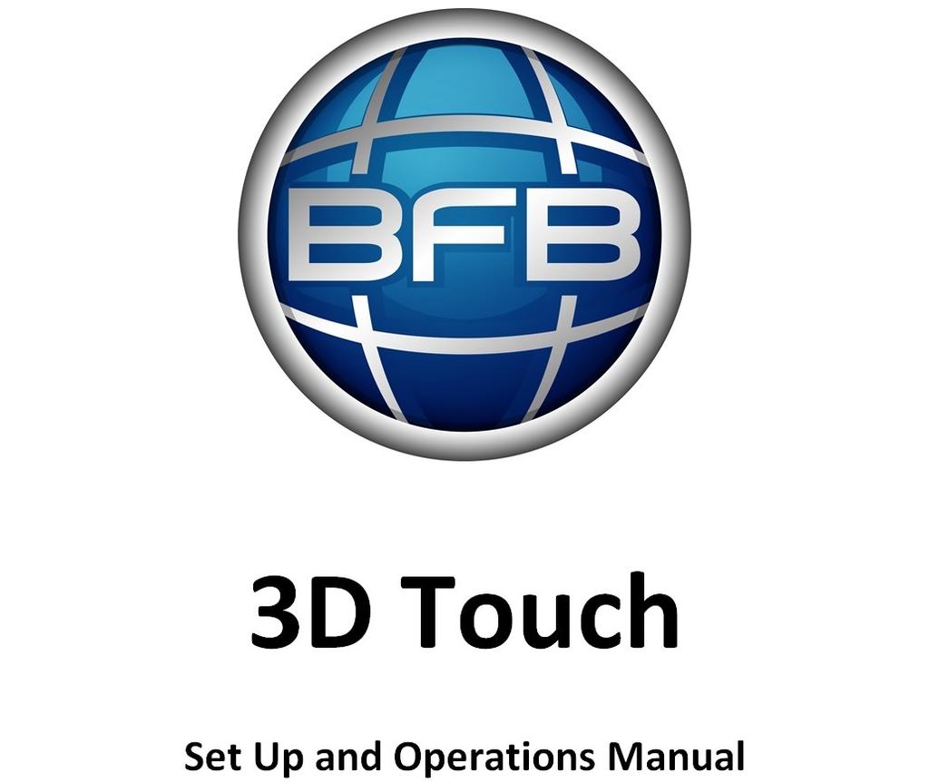
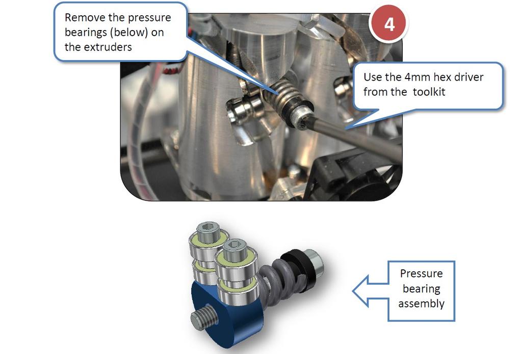
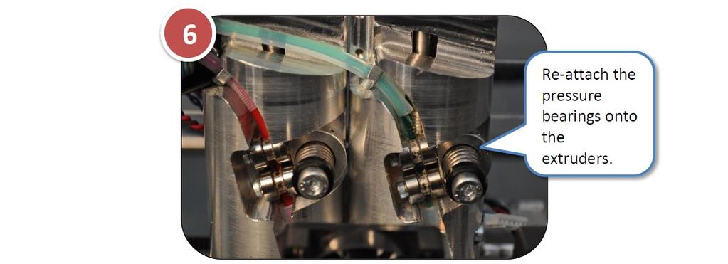
23 See c. Setting the extruder pressure bearings to refine the spring compression on the pressure bearing (nominally 12mm). Page 23
 to move the extruders to the centre of the machine, and lower the bed. This makes it easy to clean any purged material.")

24 i. Extruder control Make sure all extruders are loaded. Use 'Manual move' (see d. Test all axes) to move the extruders to the centre of the machine, and lower the bed. This makes it easy to clean any purged material. On the control panel select the Extruder control function 'Extruder control' manages one extruder at a time (E1, E2 or E3) using the buttons on the control panel. Recommended maximum extrusion temperatures for materials: Material Extrusion temperature ( C) ABS 260 PLA 195 Note: Extruders share power, therefore an extruder will heat up quicker if it is the only extruder with a high target temperature. Page 24

25 j. Purge the extruder Before purging the extruders, position the axes using the move command: position the head in the middle of the machine, and move the bed half way down the machine, away from the nozzles. This prevents damage to the bed, and allows purging to be inspected easily. Ensure filaments are loaded into the extruders, as defined in the h. Load the extruders. Make sure the springs on the extruder pressure bearings are compressed (as detailed in c. Setting the extruder pressure bearings) enough to push the filament into the teeth of the drive shaft. Proceed by purging one extruder at a time. Heat the extruder (as shown in i. Extruder control) to the maximum temperature defined below, depending on the material in the extruder: Material Extrusion temperature ( C) ABS 260 PLA 195 Once the target temperature has been achieved, turn the RPM up to 30. Examine the movement of the filament at the pressure bearing. It should slowly be driven towards the nozzle. If not, ensure that the spring pressure bearing is compressed sufficiently ( c. Setting the extruder pressure bearings). Observe the end of the nozzle. A thin bead of molten plastic should come out of the nozzle. Depending on how far the filament was loaded into the extruder, this could take several minutes. Allow material to purge for a few seconds before reducing the RPM to 0. Repeat the purge process for each extruder. Turn the machine off to allow the nozzles to cool. As the extruders cool, clean the nozzles (see "Check the hot-end nozzles are clean"). Dispose of all waste filament from the nozzle. Page 25

26 k. How to start a print Before starting any print, make sure that the all pre-print checks have been completed. The following sections will ask you to run two test files: a raft check file, and a duck. When asked to print a file you will need to follow the procedure below: Insert the memory stick into the 3D Touch USB slot. Select the Print icon: Select the correct print file using the left and right arrow keys. Touch the name of the print file to start the print. Page 26

27 l. Print a successful raft It is essential that a good raft is printed to guarantee a good build. Therefore the height of the hot-end nozzle over the bed for the first layer is critical: If the nozzle is too far away from the bed, the filament will not stick to the bed If the nozzle is too low it will not be able to extruder the filament, and there is a risk of damage to the bed and the nozzle. Page 27

.")
28 Print the raft check file If this is your first print, you can print the raft check file to gain familiarity with the print. The print files required are already included on the USB memory stick supplied in your toolkit. If you do not have these files you can download them by clicking on the icon on the left. After downloading: Unpack the files to the root of your USB stick. The printer can only see uncompressed files at the root of the USB stick i.e. do not put them inside a folder. Make sure materials are loaded as per "Load the filament". Follow the section k. How to start a print to print the appropriate raft check file for the material loaded in Extruder 1 (see table below). Material type in Extruder 1 ABS PLA File to print RaftABS_CheckFile RaftPLA_CheckFile Examine each raft pad in the check file, as detailed in the following section. Remove the raft print when complete. Examine the raft check file Page 28

29 Potential problems If the raft pad appears damaged, match the imperfection to the two scenarios below, and follow the corrective action suggested. Note that there may be some imperfections in the raft, but that the process is very forgiving and even the images shown below will generally not spoil a full print. Track ripping Page 29


30 Purge deposit Perfect the raft If analysis of the raft check file yields any problems, you will need to re-examine some of the setup stages: Error Corrective action Nozzle too high See g. Check the bed is referenced to the extruder nozzles to adjust the height at which the nozzle starts printing. Nozzle to low See g. Check the bed is referenced to the extruder nozzles to adjust the height at which the nozzle starts printing. Nozzle heights appear inconsistent across a single print Track ripping Purge deposit See f. Check the print bed is level See e. Check the hot-end nozzles are clean from plastic debris See e. Check the hot-end nozzles are clean from plastic debris Page 30
BFB-3000 BFB-3000 Plus Set Up and Operations Manual [Version 3.3]
![BFB-3000 BFB-3000 Plus Set Up and Operations Manual [Version 3.3]](/thumbs/77/74531070.jpg "BFB-3000 BFB-3000 Plus Set Up and Operations Manual [Version 3.3]") BFB-3000 BFB-3000 Plus Set Up and Operations Manual [Version 3.3] Document No: D100253 1 Introduction Thank you for purchasing your BFB-3000. Before first use, the BFB-3000 needs careful setting up. The
BFB-3000 BFB-3000 Plus Set Up and Operations Manual [Version 3.3] Document No: D100253 1 Introduction Thank you for purchasing your BFB-3000. Before first use, the BFB-3000 needs careful setting up. The
BFB-3000 Set Up and Operations Manual [Version 3.0]
![BFB-3000 Set Up and Operations Manual [Version 3.0]](/thumbs/75/72577978.jpg "BFB-3000 Set Up and Operations Manual [Version 3.0]") BFB-3000 Set Up and Operations Manual [Version 3.0] Document No: D100253 1 Introduction Thank you for purchasing your BFB-3000. Before first use, the BFB-3000 needs careful setting up. The list below illustrates
BFB-3000 Set Up and Operations Manual [Version 3.0] Document No: D100253 1 Introduction Thank you for purchasing your BFB-3000. Before first use, the BFB-3000 needs careful setting up. The list below illustrates
Introduction to 3D Printing
 TAKE HOME LABS OKLAHOMA STATE UNIVERSITY Introduction to 3D Printing by Sean Hendrix 1 OBJECTIVE The objective of this experiment is to introduce you to 3D printing, by having you print some simple parts
TL4076 Top 5 Tips Get to know your TL4076
 TL4076 Top 5 Tips Get to know your TL4076 Thermal Break with Teflon liner (behind fan) Hot End Assembly Fan Heat Block Extruder with toothed gear(brass) and idler (steel) Filament Guide Tube Nozzle Cable
3D TOUCH. Extruder upgrade. Document version 1.0
 3D TOUCH Extruder upgrade Document version 1.0 1 Summary This manual is for the installation of an additional extruder into the 3D Touch. The procedure is the same for both 1 2 head, and 2 3 head upgrades.
NWA3D A5 User Manual
 1. NWA3D A5 3D Printer Part Diagrams 2. Assembling the Spool Holder 3. Leveling the Build Plate 4. Loading and Unloading Filament 5. Operation: The Four Steps in 3D Printing 6. Troubleshooting 7. Additional
Heated Bed Installation Instructions
 Heated Bed Installation Instructions Overview The glass panel is heated by way of a heater element which is bonded to the glass panel and controlled by a digital temperature controller. The temperature
JGAURORA 3D PRINTER MODEL: A5 USER GUIDE
 JGAURORA 3D PRINTER MODEL: A5 USER GUIDE Contents ----3D Printer User Guide 1. Preface... 2 1.1 Introduction...2 1.2 Safety advice... 2 1.3 Filament requirements...2 1.4 Environmental requirements...2
Customer Name: Serial Number: Y-Axis Stall
 Technician Name: Date: Technician Name: Date: Customer Name: Serial Number: Y-Axis Stall Issue Explanation and Background Each drive motor on the machine (the x, y and z axes motors) has a sensor called
Modix Big-60 Assembly Manual Part 2
 Modix Big-60 Assembly Manual Part 2 Version 1.0, October 2017 Menu 1. Motors & End Stop Wiring... 3 2. Controller Wiring Check... 6 3. Extruder Wiring... 7 4. Electronic Box Cover... 9 5. Filament Sensor...
WANHAO Duplicator i3. User Manual V1.2. Wanhao USA
 WANHAO Duplicator i3 User Manual V1.2 Wanhao USA 2015 www.wanhaousa.com Safety WARNING: The components on the Duplicator i3 generate high temperatures and move extremely fast. Reaching inside of the Duplicator
To be the Chief Evangelist CR-10S Pro Printer Guide Book To make Top-quality 3D printer
 To be the Chief Evangelist CR-0S Pro Printer Guide Book To make Top-quality 3D printer This guide book is for standard CR-0S Pro. Please plug the power cord into a three-hole power jack. Detailed instructions
(2) Remove the customer's Waste Ink Cartridge and replace to a new one. (3) Make sure GT-541 is not in the middle of any operation.
 Remove the customer's Waste Ink Cartridge and replace to a new one. (3) Make sure GT-541 is not in the middle of any operation.") 9. Transporting Preparation before transportation Make sure the following SA5719101 service kit parts are all available. Part name Qty. Cleaning Cartridge 2 IH Head Carton 4 IH Head Case 8 Cap Tube 4 Tube
9. Transporting Preparation before transportation Make sure the following SA5719101 service kit parts are all available. Part name Qty. Cleaning Cartridge 2 IH Head Carton 4 IH Head Case 8 Cap Tube 4 Tube
Assembly Instructions of Geeetech Prusa I3 A pro
 Assembly Instructions of Geeetech Prusa I3 A pro (Version 04-11-2016) CONTENT Safety Instructions... 3 Preparation... 4 1. Unfold the box and check the package... 1 2. Assemble Y axis... 1 3. Build the
5. E-axis assembly. 5. E-axis assembly. Written By: Jakub Dolezal manual.prusa3d.com/ Page 1 of 40
 5. E-axis assembly Written By: Jakub Dolezal 2018 manual.prusa3d.com/ Page 1 of 40 Step 1 Tools necessary for this chapter Needle-nose pliers for zip tie trimming. 2.5mm Allen key for M3 screws 2mm Allen
Setup, Assembly, & Adjustment
 Setup, Assembly, & Adjustment 34877 Rev. B 1 of 8 Melco Fast Clamp Instructions The Melco Fast Clamp is a versatile clamping system for your embroidery machine. This document will walk you through the
Witbox 2. Quick start guide
 Witbox 2 Quick start guide Welcome. Thank you for choosing us. This manual will help you to use your new 3D printer correctly. Welcome to the world of Witbox 2. How do I use this manual? To make sure that
Quick Starter Manual for PrusaM201
 Quick Starter Manual for PrusaM201 Copyright Declaration The copyright of this specification belongs to the Shenzhen GETECH CO., LTD. (hereinafter referred to as the "Geeetech"), and all rights reserved.
Assembly Instructions of Geeetech Aluminum Prusa I3
 Assembly Instructions of Geeetech Aluminum Prusa I3 CONTENT Safety Instructions... 3 Preparation... 4 1. Unfold the box and check the package... 1 2. Assemble Y axis... 1 3. Build the printing platform...
3D PRINTER USER MANUAL
 3D PRINTER USER MANUAL Table of contents page: 1. Introduction 2. Table of contents 3. Basic informations 4. General information 5. Glossary 6. Starter pack s content 7. Technical parameters 8. Device
FlexJet Carriage Circuit Board (PCB) Replacement
 Replacement") P/N: 111484 R0 14140 NE 200th St. Woodinville, WA. 98072 PH: (425) 398-8282 FX: (425) 398-8383 ioline.com FlexJet Carriage Circuit Board (PCB) Replacement Notices: Warning! Ensure that all AC power cables
P/N: 111484 R0 14140 NE 200th St. Woodinville, WA. 98072 PH: (425) 398-8282 FX: (425) 398-8383 ioline.com FlexJet Carriage Circuit Board (PCB) Replacement Notices: Warning! Ensure that all AC power cables
BFB 3000 UPGRADE KIT 1
 BFB 3000 UPGRADE KIT 1 D o c u m e n t N o : D 1 0 0 2 5 2 Page: 1 Summary This document provides instructions to fit the components from the BfB 3000 Upgrade kit. Please examine your upgrade kit the packs
SERIES A & AA ROLLER DOORS INSTALLATION GUIDE
 SERIES A & AA ROLLER DOORS INSTALLATION GUIDE THESE INSTRUCTIONS ARE PROVIDED FOR USE BY EXPERIENCED INSTALLERS OF GARAGE DOORS BY UNDER-TAKING THE INSTALLATION OF THIS DOOR, THE INSTALLER UNDERSTANDS
5.5 Wheel drive (wheel pilots only)
") Chapter 5: Installing the ST4000+ 61 5.5 Wheel drive (wheel pilots only) The Raymarine wheel drive will fit 3, 4, 5, 6, 7 or 8 spoke wheels. It is designed to operate with steering systems with between
Chapter 5: Installing the ST4000+ 61 5.5 Wheel drive (wheel pilots only) The Raymarine wheel drive will fit 3, 4, 5, 6, 7 or 8 spoke wheels. It is designed to operate with steering systems with between
Service menu - Individual Filament Calibration
 Service menu - Individual Filament Calibration Written By: Jakub Dolezal 2018 manual.prusa3d.com/ Page 1 of 8 Step 1 Introduction This guide will take you through the calibration of the Bowden length on
Installation Instructions for the EVO3 Height-Adjustable Ultimate Short Shifter
 Installation Instructions for the EVO3 Height-Adjustable Ultimate Short Shifter for 1992-2005 325, 323, 318 and 1986-1994 525, 528, 535, 540 5-speed models only. (part number USSE3 and USSE5) Thank you
Automatic Roof Hatch Opener
 Automatic Roof Hatch Opener Installation Guide REQUIRED TOOLS (These tools are required to complete the installation) Cordless Drill 1/8 1/4 Drill Bits 1/8 Pin Punch #2 Philips Bit Rachet Sharpie Hammer
NWA3D A31 User Manual
 1. 3D Printer Parts Diagram 2. Assembly 3. Fine-Tuning 4. Leveling the Build Plate 5. Loading and Unloading Filament 6. Operation: The Four Steps in 3D Printing 7. Troubleshooting Version 2.0 8. Additional
The H-MAC Heavy Metal Articulating Chassis Construction Guide
 The H-MAC Heavy Metal Articulating Chassis Construction Guide The Heavy Metal Chassis is constructed with two identical drive modules built using 10 mechanical sub-assemblies. The drive modules are integrated
Maintenance Manual. Hephestos
 Hephestos 2016 Mundo Reader SL. All rights reserved. The reproduction, copying, distribution, publication or modification of this material is strictly prohibited unless carried out with the express prior
FIRST TIME INSTALLATION
 LOCKN LOAD TM PLATFORM MAX PLATFORM LOAD RATING: 100 KG (sizes A, B, F, G, I, K, & L) 150 KG (sizes C, D, E, H, J, N, P & U) PLEASE REFER TO VEHICLE MANUFACTURER SPECIFICATIONS FOR MAX ROOF LOAD RATING
Documentation version 1.42 ASSEMBLY INSTRUCTIONS REV 1.1
 Documentation version 1.42 ASSEMBLY INSTRUCTIONS REV 1.1 / 2 INTRODUCTION / 3 INTRODUCTION Target : Prupose a visual guide of the differents steps to build and use a µdelta printer Designers : Hugo Flye
Prusa i3 Printer Assembly Guide
 Prusa i3 Printer Assembly Guide Special thanks to Carlos Sanchez and Miguel Sanchez for the graphics. All graphics captured from their great animation: http://www.carlos-sanchez.com/ Prusa3/ For copyright
How To: Replace Brembo front discs & pads
 How To: Replace Brembo front discs & pads Necessary Tools required Good quality socket set. T55 Torx/spline bit of very good quality. T30 Torx/spline bit. T27 Torx /spline bit WD40 Mallet. Punch. Brake
Southwest Windpower Instruction Sheet AIR-X Circuit Replacement Kit
 Southwest Windpower Instruction Sheet AIR-X Circuit Replacement Kit Tools Required 5 / 32 Hex key 5 / 16 Hex key 7 / 64 Hex key Standard screwdriver Pair of external snap ring pliers Rubber mallet Hammer
PRSalpha Air Drill (Double Valve)
") 888-680-4466 ShopBotTools.com PRSalpha Air Drill (Double Valve) Copyright 2016 ShopBot Tools, Inc. page 1 Copyright 2016 ShopBot Tools, Inc. page 2 Table of Contents Overview...5 Spindle Mounting Plate...6
888-680-4466 ShopBotTools.com PRSalpha Air Drill (Double Valve) Copyright 2016 ShopBot Tools, Inc. page 1 Copyright 2016 ShopBot Tools, Inc. page 2 Table of Contents Overview...5 Spindle Mounting Plate...6
20 TONNE HYDRAULIC PRESS MODEL NO: CSA20FBT
 20 TONNE HYDRAULIC PRESS MODEL NO: CSA20FBT PART NO: 7614058 OPERATION & MAINTENANCE INSTRUCTIONS WARNING: Read these instructions before using the press GC0516 INTRODUCTION Thank you for purchasing this
Creatr HS Flexible filament modification V01-04
 Creatr HS Flexible filament modification V0-04 Summary This document describes the modification of the Creatr HS D printer of Leapfrog BV to print flexible filament and written with the intention of use
Australia s best value ebikes
 IMPORTANT NOTICE Read manual, Instructions and Terms carefully before use. It is the buyer s responsibility to make sure the drift trike is safe to ride. If necessary ask for help at any good local bicycle
Step-by-Step Instructions for ieq45 R.A. Worm Installation/Replacing September 2013
 Step-by-Step Instructions for ieq45 R.A. Worm Installation/Replacing September 2013 These instructions serve to explain how to Replace a R.A. worm; Adjust a RA worm/wheel meshing; Inspect and clean a RA
TBI /2012 TRAUMATIC BRAIN INJURY DEVICE
 USER MANUAL TBI 0310 6/2012 TRAUMATIC BRAIN INJURY DEVICE Page 1 of 26 Setting up the TBI 0310 Head Impactor The TBI 0310 Head Impactor when fully assembled has the following components: 1. Control box
Rekluse Motor Sports. The e-axle KTM. Installation Guide Copyright 2006 Rekluse Motor Sports e-axle Revision 1.
 Rekluse Motor Sports The e-axle 2003 2007 KTM Installation Guide Copyright 2006 Rekluse Motor Sports e-axle Revision 1.000 RMS 2733 195-2733C Manual Revision: 032207 Rekluse Motor Sports, Inc. 110 E. 43
3M Overhaul Service Kit
 SERVICE INSTRUCTIONS FOR 3M 12,000 RPM 5 in. (127 mm) and 6 in. (150 mm) RANDOM ORBITAL SANDERS 3M Overhaul Service Kit The part number 20347, 3M Overhaul Service Kit, contains all the replacement parts
3M Overhaul Service Kit
 SERVICE INSTRUCTIONS FOR 3M 12,000 RPM 3 in. (77 mm) RANDOM ORBITAL SANDERS 3M Overhaul Service Kit The part number 20346, 3M Overhaul Service Kit, contains all the replacement parts that naturally wear
CALIFORNIA TRIMMER MOWER MAINTENANCE MANUAL
 CALIFORNIA TRIMMER MOWER MAINTENANCE MANUAL 2 Table of Contents Section 1: General Information Page Handle Assembly Instructions 4 Maintenance All Models 6 Oil Change Procedures All Models 9 Height Adjustment
Building Instructions of Geeetech Prusa I3 M201
 Building Instructions of Geeetech Prusa I3 M201 (Version 11-25-2016) CONTENT Safety Instructions... 1 Preparation... 2 1. Assemble the threaded rods of Y axis... 3 2. Assemble the front and back support
Instructions for Assembling Driving Wheels, Axles and Crankpins
 Instructions for Assembling Driving Wheels, Axles and Crankpins (Version 1; October 2008) Introduction These instructions explain how to assemble Exactoscale 4mm scale driving wheels, axles and crankpins
2015 Copyright Maxspeed-Motorsports.com
 1 Porsche PCM 3.1 Backup Camera Installation Instructions. Thank you for purchasing your product at www.maxspeedmotorsports.com Before you start please understand that these installation instructions are
Documentation version ASSEMBLY INSTRUCTIONS
 Documentation version 1.6.30 ASSEMBLY INSTRUCTIONS / 2 INTRODUCTION / 3 INTRODUCTION Target : Propose a visual assembly instruction guide of the MicroDelta Rework. Designers of the MicroDelta Rework :
Operation Guide F306 Generation I
 Operation Guide F306 Generation I Revision 4 08-27-2014 Table of Contents 1. Introduction... 2 1.1. Warnings... 2 2. General Info Software... 2 2.1. Software toolchain overview... 2 2.2. Simplify3D Tutorials...
Installation Guide CLAAS Lexion Combines with 9 inch Elevators
 Installation Guide CLAAS Lexion Combines with 9 inch Elevators 955614_01 4/17 1 Table of Contents System Overview 3 Quick Start Guide 4 Flow Sensor Installation 5 Hydraulic Elevator Adjustment Kit Installation
3D PRINTER. Pack 09. Anything you can imagine, you can make! 3D technology is now available for you at home! BUILD YOUR OWN
 BUILD YOUR OWN Pack 09 Anything you can imagine, you can make! 3D PRINTER Compatible with Windows 7 & 8 Mac OS X 3D technology is now available for you at home! www.model-space.com BUILD YOUR OWN 3D PRINTER
S1 Sequential. T56 Magnum. Sequential shifter. Contents and assembly instructions
 S1 Sequential Sequential shifter T56 Magnum Contents and assembly instructions Parts List Sequential shifter x1 Base plate x1 Base spacer x1 Drill Square x1 Shaft fitting x1 Square washer x1 8mm Aluminium
Building Instruction of Geeetech Prusa I3 pro W. 3D Printer
 Building Instruction of Geeetech Prusa I3 pro W 3D Printer Version 05-31-2017 Contents Safety Instructions... 2 Preparations... 3 1.Unfold the box and check the package... 4 2 Assemble the rods of a Y
3DPrint Quality. Troubleshooting Guide
 ALUNAR 3D PRINTER Print Quality Troubleshooting Guide Print Quality Troubleshooting Guide... 1 Overview...1 1. Not Extruding at Start of Print...3 1.1 Filament was not loaded into extruder before printing...3
NOTE: DISCONNECT MAIN POWER LOCK OUT AND TAG BEFORE PERFORMING ANY PROCEDURES IN THIS SECTION.
 M E C H A N I C A L S E T U P & A D J U S T M E N T S NOTE: DISCONNECT MAIN POWER LOCK OUT AND TAG BEFORE PERFORMING ANY PROCEDURES IN THIS SECTION. NOTE: All adjustments should be made with the sealer
Quick user guide for the DM dispenser
 Quick user guide for the DM dispenser READ FIRST! Use the shortest/thickest USB cable possible, if the screen dims too much during operation (to the point where it s hard to read the text) your cable or
3 D Print Quality Troubleshooting Guide
 3 D Print Quality Troubleshooting Guide Shenzhen Anet Technology Co,. Ltd. Print Quality Troubleshooting Guide... 1 Overview... 1 1. Not Extruding at Start of Print... 4 1.1 Filament was not loaded into
3 D Print Quality Troubleshooting Guide
 3 D Print Quality Troubleshooting Guide Shenzhen Anet Technology Co,. Ltd. Print Quality Troubleshooting Guide... 1 Overview... 1 1. Not Extruding at Start of Print... 3 1.1 Filament was not loaded into
5 Removal and replacement
 5 Removal and replacement This chapter describes the removal and replacement of field-replaceable units (FRUs) only. Removal and replacement strategy User-replaceable parts Covers Internal assemblies ENWW
Installation and service instructions, warranty terms & conditions. DeeGreen. User Guide. Version 2.6
 Installation and service instructions, warranty terms & conditions DeeGreen User Guide Version 2.6 - 2 - Contents 1. Contents...- 3-2. Technical parameters...- 4-3. Safety instructions...- 4-4. Package
Desktop 5.5 Z Axis Retrofit
 Page 1 Kit parts Desktop 5.5 Z Axis Retrofit Carriage plate with stop bolt and Z proximity switch installed Zip ties Spare bolts Spindle mounting plate with stop bolt, spring mount, and rail Z proximity
PT3 Rotational Inspection and Alignment Procedure
 PT3 Rotational Inspection and Alignment Procedure Document No.: TR10955 Revision: 1.0 Date November 21, 2013 Revision History Revision Version Date Author Description 1.0 11/20/2012 T.Ojalehto Created
One- Touch Installation Instructions
 One- Touch Installation Instructions 1 1 Height Adjustable Pivot w/ screws 9 Upper Work Surface 2 Rail Mount Knobs 10 Back Cover 3 Transformer 11 Center Pivot w/ screws 4 Support Legs 12 Left Monitor Arm
STAY ON TRACK WITH THIS LINE FOLLOW BUGGY WITH :MOVE LINE FOLLOW BOARD FOR BBC MICRO:BIT
 STAY ON TRACK WITH THIS LINE FOLLOW BUGGY WITH :MOVE LINE FOLLOW BOARD FOR BBC MICRO:BIT BUILD INSTRUCTIONS LIST OF FIXINGS M3 BOLTS M3 NUTS STANDOFFS 6mm x12 x4 x4 10mm x4 x12 12mm x2 30mm x2 20mm M-F
DLF-220L Digital Label Finishing System
 USER MANUAL DLF-220L Digital Label Finishing System this product is certified: IMPORTANT: Please keep the original packaging in case of return. If we receive the system in non-original packaging, the warranty
MP Maker Pro Mk.1 P/N User's Manual
 MP Maker Pro Mk.1 P/N 33013 User's Manual CONTENTS SAFETY WARNINGS AND GUIDELINES... 3 INTRODUCTION... 5 FEATURES... 5 CUSTOMER SERVICE... 5 PACKAGE CONTENTS... 6 PRODUCT OVERVIEW... 7 Front View... 7
Installation Manual TWM Performance Short Shifter Cobalt SS/SC, SS/TC, HHR SS, Ion Redline and Saab 9-3
 Page 1 Installation Manual TWM Performance Short Shifter Cobalt SS/SC, SS/TC, HHR SS, Ion Redline and Saab 9-3 Please Note: It is preferable to park on a flat surface, as you will have to engage and disengage
TYRECONTROL «PT» A-188
 TYRECONTROL «PT» A-188 User Manual (EN) 2 Introduction The TYRECONTROL «PT» allows you to : - Measure the air pressures - Adjust the air pressures (only to decrease) - Measure the temperatures on the surface
Service Manual Air Plus Second Stage
 Service Manual Air Plus Second Stage Includes XS Series Second Stage Copyright 2002, Cressi-sub Revised 3/2002 2 Air Plus Second Stage Service Manual Contents BEFORE STARTING... 3 DISASSEMBLY... 3 PARTS
Installation Instruction of CTC DIY 3D Printer
 Installation Instruction of CTC DIY 3D Printer Focus on high-end science and technology,focus on 3D printing Zhuhai CTC Electronics Co.,Ltd. www.ctcprinter.com 1 Introduction This DIY 3D printer can be
Service Manual Air Tech Second Stage
 Service Manual Air Tech Second Stage Copyright 2002, Cressi-sub Revised 3/2002 2 Air Tech Second Stage Service Manual Contents BEFORE STARTING... 3 DISASSEMBLY... 3 PARTS CLEANING AND LUBRICATION... 9
MMR25. Instruction Manual for Operation & Maintenance. IB International. Ph:
 MMR25 Instruction Manual for Operation & Maintenance IB International www.ibinternational.com.au Ph: 07 3348 8300 Contents Introduction... 2 Identification Data... 3 Machine Controls & Components... 3
Touch plate serial number. Please save this info here for use later:
 Touch Plate Manual Touch plate serial number. Please save this info here for use later: Copyright Next Wave Automation All Rights Reserved. Version 2 April14th 2017 Updates of this manual are available
Modix Big-60 Assembly Instructions Part 1
 Modix Big-60 Assembly Instructions Part 1 Version 1.0, October 2017 Menu 1. X Idler Pulley Assembly... 3 2. Connecting X Axis Brackets to Z Profiles... 4 3. Assemble X Rails on X Top Profiles... 6 4. Assemble
CenterLine Filter Wheel
 Engineering Excellence Because Your Image Depends On It User s Guide CenterLine Filter Wheel Finger Lakes Instrumentation, LLC September 2014 WELCOME Thank you for purchasing an FLI CenterLine Filter Wheel.
MMU2 filament jam. MMU2 filament jam. Written By: Jakub Dolezal manual.prusa3d.com/ Page 1 of 7
 Written By: Jakub Dolezal 2018 manual.prusa3d.com/ Page 1 of 7 Step 1 Filament jam During filament loading or unloading the filament can get stuck (jammed). The printer will try several times to fix it
HURST COMP STICK KIT 2008 and up DODGE CHALLENGER (with AUTO-STICK) Catalog # &
 Catalog # &") FORM 159 0402 03/09 HURST COMP STICK KIT 2008 and up DODGE CHALLENGER (with AUTO-STICK) Catalog #538 0402 & 538 0403 2009 by Hurst Perfomance Thank you for purchasing the Hurst Comp Stick Kit for your
FORM 159 0402 03/09 HURST COMP STICK KIT 2008 and up DODGE CHALLENGER (with AUTO-STICK) Catalog #538 0402 & 538 0403 2009 by Hurst Perfomance Thank you for purchasing the Hurst Comp Stick Kit for your
Instruction of connection and programming of the VECTOR controller
 Instruction of connection and programming of the VECTOR controller 1. Connection of wiring 1.1.VECTOR Connection diagram Fig. 1 VECTOR Diagram of connection to the vehicle wiring. 1.2.Connection of wiring
Ultimaker 2 Extended THINK LARGE, PRINT BIG USER MANUAL V2.1
 Ultimaker 2 Extended THINK LARGE, PRINT BIG USER MANUAL V2.1 2 TABLE OF CONTENTS 1. ULTIMAKER 2 EXTENDED 4 Ultimaker 2 Extended at a glance 5 Specifications 7 2. GETTING STARTED 8 Unboxing 9 Installation
BROOKS STAIRLIFTS SUPERGLIDE 120
 BROOKS STAIRLIFTS SUPERGLIDE 120 INSTALLATION PROCEDURES CONTENTS Health And Safety Hazards 3 Unpacking the Stairlift Carriage 4 Pre-Installation Procedure 5 Box Contents 6 Installation Tools 9 1.1 Required
5. Extruder. 5. Extruder. Extruder guide. Written By: Dozuki System manual.prusa3d.com Page 1 of 16
 5. Extruder Extruder guide Written By: Dozuki System 2017 manual.prusa3d.com Page 1 of 16 Step 1 Get the necessary tools 2.5, 2 and 1.5 mm hex spanner Needle-nose pliers Step 2 3D printed parts Extruder
Building Instructions of Geeetech Prusa I3 M201
 Building Instructions of Geeetech Prusa I3 M201 (Version 04-11-2016) CONTENT Safety Instructions... 1 Preparation... 2 1. Assemble the threaded rods of Y axis... 3 2. Assemble the front and back support
INSTALLATION GUIDE CRF150R Manual Revision:
 REKLUSE MOTOR SPORTS The z-start Pro Clutch INSTALLATION GUIDE CRF150R 191-810 Manual Revision: 032508 2002 Rekluse Motor Sports Rekluse Motor Sports, Inc. 110 E. 43rd Street Boise, Idaho 83714 208-426-0659
50 TONNE HYDRAULIC PRESS MODEL NO: CSA50FP
 50 TONNE HYDRAULIC PRESS MODEL NO: CSA50FP PART NO: 7615202 OPERATION & MAINTENANCE INSTRUCTIONS WARNING: Read these instructions before using the press GC0516 INTRODUCTION Thank you for purchasing this
INSTALL MANUAL. FOR ON LINE ORDERING- E Commerce Visit Our Website
 INSTALL MANUAL FOR ON LINE ORDERING- E Commerce Visit Our Website WWW.PRESSUREGUARD.COM Contact Information Technical Support: Chris@pressureguard.com Sales Support: Sales@pressureguard.com By Phone: 615-227-6024
1 Assembly of the Y axis
 1 ssembly of the Y axis Q yclone 1 Preparing the side frames. x1 x1 x6 x12 E Printed part for right side Printed part for left side o not fully tighten the screws so that you will be able to insert the
Upgrade v3 to v3.2. SeeMeCNC Guides. Upgrade v3 to v3.2. Rostock Max v3 Uprgade to v3.2. Written By: SeeMeCNC seemecnc.dozuki.
 SeeMeCNC Guides Upgrade v3 to v3.2 Rostock Max v3 Uprgade to v3.2 Written By: SeeMeCNC 2018 seemecnc.dozuki.com/ Page 1 of 34 INTRODUCTION This guide is intended to Upgrade a Rostock Max v3 to a Rostock
Installation Instructions HURST COMPETITION AND BILLET/PLUS SHIFTER Mustang w/5-speed Manual Transmission (GT only)
") Installation Instructions HURST COMPETITION AND BILLET/PLUS SHIFTER 2005-2010 Mustang w/5-speed Manual Transmission (GT only) Catalog# 3915201 WORK SAFELY! For maximum safety, perform this installation
Installation Instructions HURST COMPETITION AND BILLET/PLUS SHIFTER 2005-2010 Mustang w/5-speed Manual Transmission (GT only) Catalog# 3915201 WORK SAFELY! For maximum safety, perform this installation
Installation Instructions for the EVO3 Height-Adjustable Ultimate Short Shifter. for F80 M3 and F82 M4
 Installation Instructions for the EVO3 Height-Adjustable Ultimate Short Shifter for 2013+ F80 M3 and F82 M4 part number USSF80 Thank you for purchasing the Ultimate Shift Kit. Please read these directions
Manifold QF. Contents. Description. Installation & Setup Guide. Safety 3. Introduction 3. Installation Standards 4. Specifications 5.
 Contents Description Page Safety 3 Introduction 3 Installation Standards 4 Specifications 5 Materials 5 Overall System Configurations 6 Manifold Installation 7 Fixing Unit to Wall 7 Water Connection 8
 AUTOGARD SERIES 820 TORQUE LIMITER Installation and Maintenance Manual DB0009 Issue 11 21 Feb 2017 British Autogard Ltd 2 Wilkinson Rd., Love Lane Industrial Estate, Cirencester, Glos., GL7 1YT UK Tel.
ECHO. User Manual. Model: PFBD77
 ECHO User Manual Model: PFBD77 Thank you for choosing ProFlight. Please read this user manual before using this drone and keep it safe for future reference. CONTENTS Safety 3 Battery Charging 4 Transmitter
710 Splicing Rig. Instructions. January E
 710 Splicing Rig Instructions January 2007 Table of Contents 1.0 General Statement...4 2.0 3M 710-UTK25A Splicing Rig and Field Maintenance Kit...4 3.0 Straight Splicing using the 3M 710 25-pair modules...6
Unpacking Instructions
 Unpacking Instructions by Revolution 3D Printers Infinity3D_Unpacking_Instructions_V1.1 1 Copyright 2016, Revolution 3D Printers Copyright 2016 Revolution 3D Printers, Victoria, BC File version Infinity3D_V1.0,
Important notice Upper supports for Z axis Pulley Corner for Y axis Right X axis and left X axis Chain coupling for left X axis
 Warranty and FAQ G004260 Important notice You can personalise your Prusa i3 HEPHESTOS and update it with the latest innovations that appear in the community. However, it is important that you understand
2013 RT / 2014RT / 2015 RT - Shock Spring Adjuster Installation Instructions
 2013 RT / 2014RT / 2015 RT - Shock Spring Adjuster Installation Instructions Billet Aluminum Adjusters (2) Shock Spring Compressors (Optional) Spanner Wrench (1) BajaRon Decals Not Shown (4) Adjuster Scuff
INSTALLATION INSTRUCTIONS AND OWNER S MANUAL
 INSTALLATION INSTRUCTIONS AND OWNER S MANUAL Thank you for purchasing the AlloyCover from WeatherTech. Manufactured with pride using superior quality materials and workmanship. With proper care, your cover
Assembly & Installation Guide Makerbot Rep2X and clones
 Assembly & Installation Guide Makerbot Rep2X and clones The Bondtech extruder upgrade kit for Makerbot and clones uses high-quality industrial pneumatic push-fit fittings for attaching the bowden tube.
The RCS-6V kit. Page of Contents. 1. This Book 1.1. Warning & safety What can I do with the RCS-kit? Tips 3
 The RCS-6V kit Page of Contents Page 1. This Book 1.1. Warning & safety 3 1.2. What can I do with the RCS-kit? 3 1.3. Tips 3 2. The principle of the system 2.1. How the load measurement system works 5