INSTALLATION & OWNER S MANUAL
|
|
|
- Mitchell Bryant
- 5 years ago
- Views:
Transcription

1 Page 1 of 16 INSTALLATION & OWNER S MANUAL YAMAHA VIKING CAB KIT WITH HARD DOORS p/n: 1YAMVK fits model years (fits Yanmar Bull model years 2017-) NOTE: By design, the doors are made to not be removable! This is a safety feature since disabling the factory quarter doors. The contents of this envelope are the property of the owner. Be sure to leave with the owner when installation is complete. APPROXIMATE INSTALLATION TIME: 3 HOURS (excluding accessories) Available options (sold separately): Low Profile 5 LED Work Lights (p/n: 9LEDW4) Switch Panel (p/n: 9PSF1) Strobe Light (p/n: 9LEDS2) Interior Rear View Mirror (p/n: 9PM3) Exterior Side View Mirrors (p/n: 9PM5) Note: Two windshield wipers are supplied with this cab kit. Rev. C, 02/08/2018 p/n: IM-YAMVK

2 Page 2 of 16 ADDED WEIGHT Curtis Cabs, blades and general accessories add additional weight to the base vehicle. All Curtis accessory weights are listed in product brochures. Deduct the accessory's total weight from the vehicle's rated capacity and never exceed the vehicle's rated capacity including driver and passenger. Exposure to Carbon Monoxide can Cause illness, serious injury or death. Never operate vehicle if suspicious of Carbon Monoxide. Inspect exhaust system for leaks monthly. Leaks can result from loose connections, corrosion, cracks or other damage to the exhaust manifold. If leaks are found, repair or replace exhaust system. Do not use vehicle until repair or replacement is complete.! WARNING DO NOT REMOVE DOOR The doors on this enclosure should not be removed under any circumstances. They are designed to remain on the vehicle at all times. PREREQUISITE: All vehicles must have the factory Yamaha Sound Damping kit, Yamaha part number 1XD-F83R0-S0-00, installed to work with this cab vehicles come with the parts of the kit installed from the factory and will fit with this cab with no additional components required. CAB INSTALLATION HELPFUL HINTS: A. Use caution to avoid damaging the factory installed threaded inserts. Begin the bolt engagement by hand to guard against potential cross threading. B. Abbreviations used throughout: O.E.M. = Original Equipment Manufacturer R.O.P.S. = Roll-Over Protective Structure C. Refer to the parts diagram at the end of the manual for easier part identification during installation. TOOLS REQUIRED: 9/32 drill bit and a drill 3/8 drive sockets (3/8, 7/16, 1/2, 3/4, 14mm) #3 Phillips head screwdriver Wire snips (for snipping wire ties) Small flat screwdriver Grease (for hinge pins and striker pins) 3/8 drive ratchet Torque Wrench Allen wrenches (5/32, 6mm, and 8mm) 5/32 Hex L-Key for Tamper-Resistant Screws Open-end wrenches (3/8, 7/16, 1/2, 3/4, 14mm)


 removable zip ties. Remove these 2 security bolts 1.3 See fig 1.")
 First Bend Cut Second Bend Approx. 1-3/4 down Fig. 1.2 (Rear plastic sound damping panel removed) Roof clamp Plastic sound damping panel Fig.")
3 Page 3 of VEHICLE PREP 1.1 See fig Remove both factory lower quarter doors. Note: there are two security screws per door. 1.2 See fig 1.2. Raise the dump bed, remove the rear plastic sound damping panel, and trim just below the second bend as shown, approximately 1-3/4 down from the outer top edge. The panel is secured with (4) removable zip ties. Remove these 2 security bolts 1.3 See fig 1.3. Reinstall the panel. 1.4 See fig 1.4. Remove roof clamps and hardware and save for later use. Fig. 1.1 (View of front right corner) First Bend Cut Second Bend Approx. 1-3/4 down Fig. 1.2 (Rear plastic sound damping panel removed) Roof clamp Plastic sound damping panel Fig. 1.3 (Rear plastic sound damping panel reinstalled) Fig. 1.4 (Roof clamps)

 at this time. Repeat for left side. 4. DOOR SEAL PANEL 4.1 See fig. 4.1. Install using the following hardware: 2 1/4-20 x 3/4 long Button Head Bolts 2 1/4-20 Hex Flange Nuts Fig.")

4 Page 4 of ROOF 2.1 See fig Install the supplied bulb rubber to the right side of the plastic roof by flexing the edge of the roof up enough to push it on. Repeat for left side. 2.2 If the roof is not centered on the vehicle, it should be centered at this time. 3. STRIKER 3.1 See fig Install using the following hardware: 2 3/8-24 x 2-1/4 Long Hex Bolts 2 3/8-24 Nylock Nuts 4 3/8 I.D. x 13/16 O.D. Washers 3.2 Torque to 47 ft.-lbs. (64 N-m) at this time. Repeat for left side. 4. DOOR SEAL PANEL 4.1 See fig Install using the following hardware: 2 1/4-20 x 3/4 long Button Head Bolts 2 1/4-20 Hex Flange Nuts Fig. 2.1 (View of front right corner) Start bulb rubber here Discard O.E.M. hardware. Install new bolts, washers, and nuts. 4.2 Note: occupy the top hole where security bolt was removed from. 4.3 Push down against body panel for a good seal. 4.4 Tighten hardware at this time. 4.5 Repeat for left side. Front Striker Mount Fig. 3.1 (View of front right corner) Heads of bolts here Door Seal Panel Fig. 4.1 (View of front right corner)


5 Page 5 of REAR PANEL MOUNT Rear Panel Mount 5.1 See fig Install Rear Panel Mount. 5.2 Torque all four bolts to 47 ft.-lbs. (64 N-m) at this time. Repeat for left side. 6. REAR LEGS 6.1 Raise the dump bed. 6.2 See fig Mount the O.E.M. roof clamp to the R.O.P.S. tubing toward the bottom as shown. Leave bolts loose at this time. Repeat for left side. 6.3 See fig Remove and discard the O.E.M. cross bolt and nut. Keep the two O.E.M. curved washers. They are to be reinstalled in the same orientation against the front and back of the R.O.P.S. tubing. A B Loosen bolts A and B for ease of install. Remove and reuse bolts C and D Fig. 5.1 (View of rear right corner) C D 6.4 See fig Position the rear leg as shown. Loosely install the 1/2 x 1 long bolt in the top to hold the leg in place, then install the following hardware where the O.E.M. hardware was removed. Be sure the curved washers are against the R.O.P.S. tubing and the flat washers are under the head of the bolt and nut. Do not tighten at this time. 1 1/2 x 1 Long Hex Flange Bolt 1 3/8-24 x 3 Long Hex Head Bolt 1 3/8-24 Nylock Nut 2 3/8 I.D. x 13/16 O.D. Washers 2 Curved O.E.M. Washers O.E.M. roof clamp Fig. 6.2 (View of rear right corner) Rear Leg First, loosely install this 1/2 bolt Keep O.E.M curved washers Second, loosely install the new bolt, washers, and nut Fig. 6.3 (View of rear right corner) Fig. 6.4 (View of rear right corner)
 thread cutting 5/16-18 flanged head bolts and (6) regular 5/16-18 flanged head bolts in the hardware kit.")
 6.6 See fig. 6.6. Clamp the rear leg to the R.O.P.S. and torque the 3/8-24 bolts to 47 ft.-lbs. (64 N-m) at this time.")

")
6 Page 6 of REAR LEGS cont d 6.5 See fig Secure the top R.O.P.S. clamp and the roof to the top of the rear leg using the following hardware: 2 5/16-18 x 3/4 Long Hex Flange Bolt 2 O.E.M. Roof mounting bolts 2 O.E.M. Roof mounting nuts Tighten bolts at this time. R.O.P.S. clamp O.E.M. roof hardware NOTE: There are (4) thread cutting 5/16-18 flanged head bolts and (6) regular 5/16-18 flanged head bolts in the hardware kit. Set aside the thread cutting bolts for use in step 10.2 on page 11 so they are not accidently used in the wrong place. 5/16-18 bolts Fig. 6.5 (View of rear right corner) 6.6 See fig Clamp the rear leg to the R.O.P.S. and torque the 3/8-24 bolts to 47 ft.-lbs. (64 N-m) at this time. 6.7 See fig Torque the 1/2 bolt to 47 ft.-lbs. (64 N-m) at this time. 6.8 See fig 6.8. Using the following hardware, attach the rear leg to the O.E.M. roof bracket. Tighten all hardware at this time. 2 1/4-20 x 3/4 Long Button Head Bolt 2 1/4-20 Nylock Nuts 3/8 hardware 6.9 Repeat for left side. Fig. 6.6 (View of rear right corner) 1/2 Bolt 1/4-20 Hardware O.E.M. Clamp hardware Fig. 6.7 (View of rear right corner) Fig. 6.8 (View of rear right corner)
 at this time. Repeat for left side. 8. WINDSHIELD 8.1")

 Upper Mounting Bracket with open-ended slot Loosen this fastener for ease of installation Fig. 8.")
7 Page 7 of GAS SHOCK MOUNT 7.1 See fig Slide the open-ended slot on the Gas Shock Mount under the head of the front loosened bolt. Reinstall the rear bolt through the Gas Shock Mount bolt hole. Torque both bolts to 47 ft.-lbs. (64 N-m) at this time. Repeat for left side. 8. WINDSHIELD 8.1 See fig Loosen two factory installed bolts holding the Upper Mounting Brackets in place (one per bracket). 8.2 See fig Loosen the front-most O.E.M. bolt per side as shown (one per side). With assistance, place the windshield assembly on the vehicle and slide the open-ended slots on the windshield around the loosened R.O.P.S. bolts. Just loosen this front inboard bolt Gas Shock Mount Temporarily remove and reuse this rear inboard bolt Fig. 7.1 (View of inner right side) Upper Mounting Bracket with open-ended slot Loosen this fastener for ease of installation Fig. 8.1 (View of top right corner of windshield assembly) Loosen this front O.E.M. bolt. Repeat for left side of vehicle. Fig. 8.2 (View of inner right side)
.")

 8.7 See fig. 8.7. Torque both loosened R.O.P.S. bolts (one per side) to 47 ft.")
 Step 2: Tighten this bolt Feed the two wiper wires down thru the gap between the body panel and the R.O.P.S. tubing, then install the 5/16 bolt (1 per side) Step 1: Torque this O.")
8 Page 8 of WINDSHIELD cont d. 8.3 See fig Make sure the riveted rubber flap is not bunched up. Gently use a small flathead screwdriver to reposition flap and seal better if necessary. 8.4 See fig Make sure the rubber seal for the R.O.P.S. tubing is loose and outboard as shown (not bound up). 8.5 Per fig. 8.5, pass the ends of the wiper wires down thru the gap around the R.O.P.S. tubing so that a harness connection may be made in a later step underneath the fender area. 8.6 See fig Use the following hardware into the lower threaded inserts (one bolt per side): 2 5/16 x 3/4 long hex flanged bolts Push bottom of windshield tight against hood and tighten bolts at this time. Ensure that rubber flap seals well Fig. 8.3 (View of inner right side) 8.7 See fig Torque both loosened R.O.P.S. bolts (one per side) to 47 ft.-lbs. (64 N-m) at this time. Tighten the 5/16 bolts (one per side) which were loosened for ease of installation. Rubber seal for R.O.P.S. tube Fig. 8.4 (View of right side) Step 2: Tighten this bolt Feed the two wiper wires down thru the gap between the body panel and the R.O.P.S. tubing, then install the 5/16 bolt (1 per side) Step 1: Torque this O.E.M. bolt Bolt Fig. 8.7 (View of inner right side) Fig. 8.5 (Inside view of driver s side)


 (9/32 drill bit).")
9 Page 9 of WINDSHIELD cont d. 8.8 See fig Wrap the rubber seal around the R.O.P.S. tube and attach it to itself via the factory installed Velcro. Re-tighten the top edge if necessary to achieve a tight seal. The bottom edge marked A is not critical. Rubber seal for post. Ensure that you position the top edge tight to the post to keep water out. The slightest of gaps will allow water into the cab area. 9. REAR PANEL 9.1 Open dump bed. 9.2 See fig With assistance, place the Rear Panel Assembly in place. Use the following hardware to secure: 4 1/4-20 x 1-1/2 long Button Head bolts 4 1/4-20 hex flanged nuts 4 1/4 x 1 O.D. fender washers Install the top bolts first, then the lower bolts. Just snug the bolts so the rubber bushings are partially compressed. 9.3 See fig Pull the rear of the plastic roof down against the rubber seal on top of the Rear Panel. From the inside of the vehicle, drill thru the bracket and thru the plastic roof (one place per bracket, two holes total) (9/32 drill bit). Use the following hardware to secure: 2 1/4-20 x 3/4 long Button Head bolts 2 1/4-20 hex flanged nuts 2 1/4 x 1 O.D. fender washers Tighten bolts at this time. Fig. 8.8 (View of right side) Bolt head and fender washers outboard here as shown A Fig. 9.2 (View of right rear side) Install the nut here. The fender washer and bolt head to be on the outboard side Fig. 9.3 (View of inner right side)


10 Page 10 of REAR PANEL cont d. 9.4 See fig Use two of the supplied wire ties to secure the bottom of the rear panel to the R.O.P.S. tubing as shown. One place on driver s side and one place on passenger s side. 9.5 See fig Press the plastic rear panel against the metal rear panel extension and drill thru the plastic panel using the pre-drilled holes in the metal panel as a guide (one hole per side, two holes total) (9/32 drill bit). Use the following hardware to secure: 2 1/4 x 3/4 long Button Head bolts 2 1/4 hex flanged nuts Tighten bolts at this time. 9.6 See fig Apply the supplied Arch PSA rubber to the RO.P.S. tube to seal against the plastic rear panel as shown. For best adhesion, apply to a clean, dry surface. Repeat on passenger s side. Wire tie Fig. 9.4 (View of driver s side) 9.7 Lower the dump bed. Button Head Bolt here on the outboard side. Flanged nut on the inside. Fig. 9.5 (View of driver s side) ROPS Tube Arch PSA rubber Fig. 9.6 (View of driver s side)


 Thread cutting slots Fig. 10.2a (Thread cutting bolt) Thread cutting bolts Door filler panel Fig.")
11 Page 11 of LOWER DOOR FILLER 10.1 See fig Unscrew and remove two plastic clips holding the side panel to the vehicle See fig. 10.2a and 10.2b. Using the supplied thread cutting bolts, carefully attach the door filler panel to the vehicle. Ensure the thread cutting bolts start going in straight and apply pressure as they are turned. As the bolts start cutting thread, there will be more resistance, and then they will turn more freely once the threads have been cut. Gently tighten them, being careful not to strip the newly cut threads. 2 5/16-18 x 3/4 long thread cutting hex flanged bolts 10.3 Repeat on driver s side. O.E.M. Plastic clips Fig (View of passenger s side) Thread cutting slots Fig. 10.2a (Thread cutting bolt) Thread cutting bolts Door filler panel Fig. 10.2b (View of passenger s side)


12 Page 12 of DOORS NOTE: by design, the doors are made to not be removable! This is a safety feature since disabling the factory quarter doors See fig Apply grease (not supplied) to both hinge pins. Install one brass washer to the top hinge pin. Install the door by engaging just the top hinge pin and then shutting the front of the door so that it engages properly into the striker pin See fig Use the following hardware: 2 5/16 x 1-1/2 long Button Head bolts 2 5/16 hex flanged nuts For ease of hardware installation, open the rear of the door slider by pushing it forward. Install one brass washer on the greased upside down lower hinge pin, install the Lower Door Hinge Plate, and loosely install the bolts and nuts with the bolt heads outboard See fig Have an assistant unlatch, open, and lift the door slightly while the lower two bolts are tightened. Do not over tighten. Over tightening will crush (damage) the structural tubing. Torque to 40 in.-lbs. Note: the top of the door should end up approximately visually parallel with the side of the roof. The door latch may need adjustment. Do not shut the door completely. The top hinge can be loosened and adjusted to achieve best alignment. CAUTION: for safe operation, do not drive with doors open. Make sure doors are closed and properly latched when driving. Brass washer and grease Fig (View of right side) Brass washer and grease Fig (View of lower right door) Mounting holes Open door and lift slightly Fig (View of right door)

. 12.")


13 Page 13 of DOORS cont d After the door is aligned parallel to the roof edge, a latch adjustment can be made. See fig The door latch engagement is adjustable in various directions. Adjust to suit. Note: the striker pin would require 3/4 openend wrenches. Note: the door latch is a rotary type with two positions to close. Adjust door so that when fully closed door latch clicks twice for total engagement. If striker pin is adjusted, make sure the finger guard ends up being centered and facing inward See fig Install the gas shocks so the thin rod end connects to the door (for best internal seal lubrication of the gas shocks). 12. ELECTRICAL FOR WIPERS One striker pin Two Phillips head bolts Fig (View of inner right side) Two 1/4 bolts 12.1 See fig Open and temporarily remove the hood. Disconnect the negative and positive battery terminals. Connect the ring terminal on the red fused wire on the wiper harness to the positive battery terminal and reconnect. Connect the ring terminal on the black wire on the harness to the negative battery terminal and reconnect. Tighten both connections See fig Route the harness through the opening on the driver s side. Wire tie the harness to the tube under the fender. Make the connection and test the wiper operation Re-install the hood. Thin rod end of gas shock 13. LUBRICATION 13.1 Once the doors are properly adjusted, lubrication (preferably grease) can be applied to the striker bolts and door latch assemblies. Re-apply periodically as needed (same goes for the door pin hinges as necessary). Fig (View of right side) Wire tie harness to this tube Fig (View under front driver s side fender) Fig (View with hood removed)
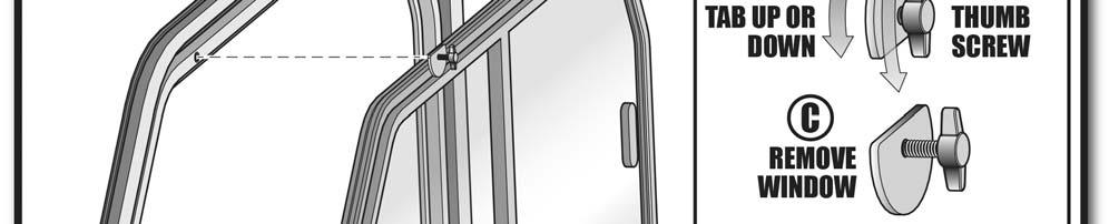
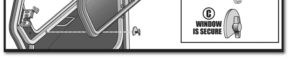
14 Page 14 of 16 YAMAHA VIKING CAB ENCLOSURE CUSTOMER INFORMATION PAGE PN: 1YAMVK! WARNING DO NOT REMOVE DOOR The doors on this enclosure should not be removed under any circumstances. They are designed to remain on the vehicle at all times. CAB FEATURES: 1) The sliding windows on the door are designed to be removable in warm weather. They are held in place with thumb screws. See the next page for an illustration. A) To remove a window, loosen the four thumb screws and rotate the retaining tabs. Once window is out, retighten the thumb screws to hold tabs in place so that they are not misplaced. B) To re-install a window, loosen the four thumb screws and place window into position. Rotate the bottom retaining tabs upward and tighten the thumb screws. Be sure to compress the sealing gasket around the window by hand to ensure that the retaining tab is completely tight. CARE AND MAINTENANCE: 1) Check and tighten hardware after 40 hours of operation. Periodically inspect and tighten hardware for the remainder of the unit s life. 2) Be sure to regularly grease hinges. Also lubricate moving parts in the door latches. 3) When trailering vehicle, be sure that all windows are closed and securely latched. 4) The wipers are fused under the hood with a glass 10A fuse (AGC Style). Do not replace with a fuse other than the size specified. IMPORTANT CLEANING INFO: 1) NEVER USE AN ALCOHOL-BASED PRODUCT FOR CLEANING. Do not use WINDEX, GLASS PLUS, FANTASTIC, etc. Do not use any CITRUS BASED CLEANERS such as orange or lemon. Use of these products will cause the cab windows to become permanently damaged. 2) Wash with a mild soap or detergent (specifically a dish liquid or equivalent) using your bare hands to free or dislodge any caked-on dirt or other foreign particles. 3) NEVER USE AN ABRASIVE DETERGENT/ VEHICLE CLEANER OR A WIRE BRISTLED BRUSH. 4) A soft, grit-free cloth, sponge, or chamois may be used but only as a means of carrying water to the windows. 5) The interior should be lightly dusted (NOT WIPED) with a clean soft cloth or chamois. The cloth or chamois should be kept free of grit by frequent rinsing in clean water. 6) Grease and oil may be removed with kerosene. 7) Novus I and Novus II are recommended plastic cleaners for acrylic units and can be used to remove light scratches.


15 Page 15 of 16
16 Page 16 of 16 YAMAHA VIKING CAB SERVICE PARTS (p/n: 1YAMVK) DOORS QTY. P/N 1L 8SV-VK07L-B4 1R 8SV-VK07R-B4 RIGHT WINDSHIELD REAR PANEL ASSEMBLY QTY. P/N QTY. P/N 1 8SV-VK02-B4 1 8SV-VK06-B4 LEFT GAS SHOCK MOUNT QTY. 1L 1R P/N 8SV-VK16L-B4 8SV-VK16R-B4 REAR PANEL MOUNT RIGHT QTY. 1L 1R P/N 8SV-VK11L-B4 8SV-VK11R-B4 RIGHT LEFT REAR LEG RIGHT QTY. 1L 1R P/N 8SV L 8SV R LEFT ROPS CLAMP LEFT QTY. P/N 1 8SV DOOR SEAL PANEL RIGHT QTY. 1L 1R P/N 8SV-VK17L-B4 8SV-VK17R-B4 LEFT STRIKER RIGHT QTY. P/N 1L 8SV-VK08L-B4 1R 8SV-VK08R-B4 LOWER DOOR HINGES RIGHT QTY. 1L 1R P/N 8SV-VKDHBL-B4 8SV-VKDHBR-B4 LEFT LOWER DOOR FILLER QTY. 1L 1R LEFT P/N 8SV-SM L 8SV-SM R RIGHT LEFT
INSTALLATION & OWNER S MANUAL
 p. 1 of 13 INSTALLATION & OWNER S MANUAL Polaris Ranger 400-EV PathPro SS Cab (fits 2010 - current) (p/n: 1PRG400FS) The contents of this envelope are the property of the owner. Be sure to leave with the
INSTALLATION & OWNER S MANUAL
 p. 1 of 15 INSTALLATION & OWNER S MANUAL Polaris Ranger 500-800 PathPro SS Cab (fits 2010 - current) (p/n: 1POLRFS1) The contents of this envelope are the property of the owner. Be sure to leave with the
INSTALLATION & OWNER S MANUAL
 Rev. C, p. 1 of 18 INSTALLATION & OWNER S MANUAL KUBOTA RTV 400 CAB (Not for use on RTV 500) These instructions are for installation of the complete cab as well as the modular components. DESCRIPTION:
INSTALLATION & OWNER S MANUAL
 Pg. 1 of 14 INSTALLATION & OWNER S MANUAL John Deere Gator XUV 825i S4 Cab (p/n: 1GTRXUV4 Steel Cab with Doors) The contents of this envelope are the property of the owner. Be sure to leave with the owner
Assembly Instructions
 Assembly Instructions Part Number Description Model Approx. Assembly Time 99994-049 Cab Enclosure MULE SX 3-4 Hours WARNING Improper installation of this accessory could result in an accident causing serious
INSTALLATION & OWNER S MANUAL
 Rev. A, p. 1 of 6 INSTALLATION & OWNER S MANUAL YANMAR SA-424 WINDSHIELD KIT P/N 1CYSA4WS FITS SA-424 TRACTORS WITH 4 POST ROPS The contents of this envelope are the property of the owner. Be sure to leave
INSTALLATION & OWNER S MANUAL
 p. 1 of 15 INSTALLATION & OWNER S MANUAL John Deere Gator PathPro SS Cab (fits all HPX and XUV models with the O.P.S. system installed) (p/n: 1GTRXUV) (O.P.S. = Operator Protective Structure) The contents
INSTALLATION & OWNER S MANUAL
 Rev. E p. of 3 INSTALLATION & OWNER S MANUAL V446 Front Cab Kit and V446 Rear Cab Kit for RTV 40 INSTALLATION & OWNER S MANUAL The contents of this envelope are the property of the owner. Be sure to leave
INSTALLATION & OWNER S MANUAL
 INSTALLATION & OWNER S MANUAL CAB INSTALLATION INSTRUCTIONS JOHN DEERE 4000 SERIES (4500/4600/4700) (4510/4610/4710) (4120/4320/4520/4720) HARD SIDED CAB ENCLOSURE (p/n 1JD4120AS) SOFT SIDED CAB ENCLOSURE
INSTALLATION & OWNER S MANUAL
 Rev. B, p. 1 of 25 INSTALLATION & OWNER S MANUAL POLARIS RANGER RCS (for models XP or HD) (for model years 2009-) cab without doors kit (p/n 1POLRCWD) cab with doors kit (p/n 1POLRC) doors only kit (p/n
INSTALLATION & OWNER S MANUAL
 Rev. K, p. 1 of 11 INSTALLATION & OWNER S MANUAL POLARIS FREEDOM CAB INSTALLATION INSTRUCTIONS FOR THE POLARIS RANGER (p/n 2876196-067) IMPORTANT: THIS ACCESSORY WEIGHS 340 POUNDS. PLEASE ADJUST THE VEHICLE
INSTALLATION & OWNER S MANUAL
 Rev. A, p. of 0 INSTALLATION & OWNER S MANUAL MASSEY FERGUSON GC2400 cab kit p/n MFGC2400 Installation Instructions The contents of this envelope are the property of the owner. Be sure to leave with the
INSTALLATION & OWNER S MANUAL
 INSTALLATION & OWNER S MANUAL CAB INSTALLATION INSTRUCTIONS KUBOTA GRAND L 30 SERIES HARD SIDED CAB ENCLOSURE (p/n 1KU3AS) SOFT SIDED CAB ENCLOSURE (p/n 1KU3SS) This Curtis Cab is designed and manufactured
INSTALLATION & OWNER S MANUAL
 p. 1 of 13 INSTLLTION & OWNER S MNUL Kubota X 70 Series Cab (fits X2370, X2670, and X25D) (p/n: 1KX70S Steel Cab) (p/n: 1KX70SS Vinyl Cab) The contents of this envelope are the property of the owner. e
INSTALLATION & OWNER S MANUAL
 Rev. L p. 1 of 16 INSTALLATION & OWNER S MANUAL V4262 CAMO (SOFT SIDED) CAB KIT INSTALLATION & OWNER S MANUAL The contents of this envelope are the property of the owner. Be sure to leave with the owner
INSTALLATION & OWNER S MANUAL
 Rev. C, p. of 2 INSTALLATION & OWNER S MANUAL KUBOTA B2650/3350 Hard Sided Cab p/n KB33AS Soft Sided Cab p/n KB33SS Installation Instructions The contents of this envelope are the property of the owner.
INSTALLATION & OWNER S MANUAL
 Rev. D, p. 1 of 14 INSTALLATION & OWNER S MANUAL Bobcat CT 230 and KIOTI CK30 cab kit with hard doors and soft rear curtain p/n 1BCT230 & 1KTCK30 The contents of this envelope are the property of the owner.
INSTALLATION & OWNER S MANUAL
 INSTALLATION & OWNER S MANUAL This Curtis Cab is designed and manufactured for use only as reasonable weather protection. This cab is not applicable, Nor should the cab be considered as protection against
INSTALLATION & OWNER S MANUAL
 INSTALLATION & OWNER S MANUAL CAB INSTALLATION INSTRUCTIONS JOHN DEERE 3000 SERIES (4200/4300/4400) (4210/4310/4410) & (3120/3320/3520/3720) HARD SIDED CAB ENCLOSURE (p/n 1JD3520AS) SOFT SIDED CAB ENCLOSURE
INSTALLATION & OWNER S MANUAL
 INSTALLATION & OWNER S MANUAL CAB INSTALLATION INSTRUCTIONS MASSEY FERGUSON THX FOR MASSEY FERGUSON 528, 53, AGCO ST28A, ST33A, CHALLENGER MT255B SOFT SIDED CAB ENCLOSURE (p/n MFTHXSS) This Curtis Cab
INSTALLATION & OWNER S MANUAL
 INSTALLATION & OWNER S MANUAL CAB INSTALLATION INSTRUCTIONS JOHN DEERE GATOR HPX and/or XUV HARD SIDED CAB ENCLOSURE (p/n: 1GTR44AS) SOFT SIDED CAB ENCLOSURE (p/n: 1GTR44SS) 111 HIGGINS STREET, WORCESTER,
INSTALLATION & OWNER S MANUAL
 Rev. G, p. 1 of 19 INSTALLATION & OWNER S MANUAL YANMAR Sc SERIES cab kit with hard doors and soft rear curtain Curtis p/n: 1CYSC1AS Yanmar p/n: 59A40056727 Optional Hard Rear Panel Curtis p/n: SC100-06A
INSTALLATION & OWNER S MANUAL
 INDUSTRIES, LLC. INSTALLATION & OWNER S MANUAL CAB INSTALLATION INSTRUCTIONS KUBOTA GRAND L 40 SERIES HARD SIDED CAB ENCLOSURE (p/n 1KGL4AS) This Curtis Cab is designed and manufactured for use only as
INSTALLATION & OWNER S MANUAL
 Rev. R p. 1 of 16 INSTALLATION & OWNER S MANUAL V4211 HARD SIDED CAB KIT and/or V4275 CAMO HARD SIDED CAB KIT INSTALLATION & OWNER S MANUAL The contents of this envelope are the property of the owner.
INSTALLATION & OWNER S MANUAL
 INSTALLATION & OWNER S MANUAL CAB INSTALLATION INSTRUCTIONS JOHN DEERE 4000 SERIES (4500/4600/4700) (4510/4610/4710) (4120/4320/4520/4720) HARD SIDED CAB ENCLOSURE (p/n 1JD4120AS) SOFT SIDED CAB ENCLOSURE
INSTALLATION & OWNER S MANUAL
 p. 1 of 15 INSTALLATION & OWNER S MANUAL YANMAR Sc2450 cab kit with hard doors and soft rear curtain Curtis p/n: 1CYSC2450AS The contents of this envelope are the property of the owner. Be sure to leave
INSTALLATION & OWNER S MANUAL
 INSTALLATION & OWNER S MANUAL CAB INSTALLATION INSTRUCTIONS FOR MASSEY FERGUSON 233, 428v (gear), 428v (hydro) SOFT SIDED CAB ENCLOSURE (p/n: MF233SS) This Curtis Cab is designed and manufactured for use
INSTALLATION & OWNER S MANUAL
 INSTALLATION & OWNER S MANUAL CAB INSTALLATION INSTRUCTIONS FOR E-Z-GO MPT BALL CAGE (p/n 72685-G01) The contents of this envelope are the property of the owner. Be sure to leave with the owner when installation
INSTALLATION & OWNER S MANUAL
 Rev. K, p. 1 of 19 INSTALLATION & OWNER S MANUAL V4210 CAB KIT (color: orange) and/or V4220 CAB KIT (color: camo) INSTALLATION & OWNER S MANUAL The contents of this envelope are the property of the owner.
INSTALLATION & OWNER S MANUAL
 INSTALLATION & OWNER S MANUAL INSTALLATION INSTRUCTIONS KAWASAKI MULE 4000 TRANS 4 FRONT CAB KIT (p/n: KAF40T-001WA and p/n: KAF40T-001BA) NOTE: Hard sided doors, soft sided doors, and rear cab are sold
INSTALLATION & OWNER S MANUAL
 Rev. D, p. 1 of 29 INSTALLATION & OWNER S MANUAL YAMAHA VIKING YXM 700 ClearView Cab p/n: 1YAMVKCV fits model years up thru 2018 (fits Yanmar Bull model years up thru 2018) The contents of this envelope
INSTALLATION & OWNER S MANUAL
 INSTALLATION & OWNER S MANUAL INSTALLATION INSTRUCTIONS KAWASAKI MULE 4000 CAB KIT (p/n: KAF40-005WA and KAF40-005BA) NOTE: Hard sided doors are sold separately. This manual is the property of the owner.
INSTALLATION & OWNER S MANUAL
 Rev. L, p. 1 of 18 INSTALLATION & OWNER S MANUAL KUBOTA L3200, L3800, and L2501 WorkPro Hard Sided Cab (p/n: 1KL38AS) WorkPro Soft Sided Cab (p/n: 1KL38SS) An optional Hard Rear Panel can be purchased
INSTALLATION & OWNER S MANUAL
 Rev. B, p. 1 of 18 INSTALLATION & OWNER S MANUAL KAWASAKI TERYX ClearView Cab p/n: 1KAWT8002CV This cab fits model years: 2014- The contents of this envelope are the property of the owner. Be sure to leave
KUBOTA BX-1500/1800/2200 HARD SIDED CAB (p/n 1KBXAS) SOFT SIDED CAB (p/n 1KBXSS)
 SOFT SIDED CAB (p/n 1KBXSS)") TRACTOR CAB INC. 111 HIGGINS STREET, WORCESTER, MA 01606 KUBOTA BX-1500/1800/2200 HARD SIDED CAB (p/n 1KBXAS) SOFT SIDED CAB (p/n 1KBXSS) INSTALLATION AND OWNER S MANUAL The contents of this envelope are
TRACTOR CAB INC. 111 HIGGINS STREET, WORCESTER, MA 01606 KUBOTA BX-1500/1800/2200 HARD SIDED CAB (p/n 1KBXAS) SOFT SIDED CAB (p/n 1KBXSS) INSTALLATION AND OWNER S MANUAL The contents of this envelope are
INSTALLATION & OWNER S MANUAL
 Rev. C p. 1 of 21 INSTALLATION & OWNER S MANUAL F5205 HARD SIDED CAB KIT INSTALLATION & OWNER S MANUAL The contents of this envelope are the property of the owner. Be sure to leave with the owner when
INSTALLATION & OWNER S MANUAL
 Rev. C, p. 1 of 24 INSTALLATION & OWNER S MANUAL HONDA PIONEER 700-2 ClearView Cab p/n: 1HONP7002CV This cab fits model years up thru 2016. The contents of this envelope are the property of the owner.
INSTALLATION & OWNER S MANUAL
 INSTALLATION & OWNER S MANUAL CAB INSTALLATION INSTRUCTIONS MASSEY FERGUSON TGX SERIES SOFT SIDED CAB ENCLOSURE (p/n MFTGXSS) This Curtis Cab is designed and manufactured for use only as reasonable weather
INSTALLATION & OWNER S MANUAL
 Page 1 of 18 INSTALLATION & OWNER S MANUAL John Deere 3 Family Premium Cab p/n: 1JD3FPR Standard Cab p/n: 1JD3FST Fits Tractor Models: 3033R, 3039R, 3046R Premium Cab Shown with Optional Front LED Work
INSTALLATION & OWNER S MANUAL
 Page 1 of 20 INSTALLATION & OWNER S MANUAL John Deere 4 Family Premium Cab p/n: 1JD4FPR Fits Tractor Models: 4044R, 4052R, 4066R Premium Cab Shown with Optional Front Work Lights. Available Options: 1.
INSTALLATION & OWNER S MANUAL
 Rev. C, p. 1 of 24 INSTALLATION & OWNER S MANUAL HONDA PIONEER 700-4 ClearView Cab p/n: 1HONP7004CV fits model years up thru 2017 The contents of this envelope are the property of the owner. Be sure to
INSTALLATION & OWNER S MANUAL
 1 of 22 INSTALLATION & OWNER S MANUAL Kawasaki Mule PRO-FXT p/n s: 1KAPFXTCA & 1KAPFXTCAS1 fits all Mule Pro 6-Passenger Models Cab Shown with Optional Front Wiper, Lights, and Side View Mirrors Available
INSTALLATION & OWNER S MANUAL
 Page 1 of 30 INSTALLATION & OWNER S MANUAL John Deere 1 Family Premium Cab p/n: 1JD1FPR Standard Cab p/n: 1JD1FST Fits Tractor Models: 1023E and 1025R Premium Cab Shown with Optional Front LED Work Lights.
Assembly Instructions
 Assembly Instructions Part Number Description Model Approx. Assembly Time 99994-0903 Windshield Wiper Kit Mule SX 1 Hour WARNING Improper installation of this accessory could result in an accident causing
INSTALLATION & OWNER S MANUAL
 Page 1 of 20 INSTALLATION & OWNER S MANUAL Massey Ferguson GC1700 Series All Steel Cab p/n: 1MFGC1700AS1 Soft Side Cab p/n: 1MFGC1700SS1 Fits Tractor Models: GC1705, GC1710, GC1715, GC1720 All Steel Cab
INSTALLATION & OWNER S MANUAL
 1 of 12 INSTALLATION & OWNER S MANUAL KAWASAKI MULE Pro FX-FXT CORNER FLASHER KIT p/n: 1KAPFXCFL Required Accessories: Fuse Panel: Kawasaki P/N: KAF080-076 Or Curtis P/N: 1KAPFXFP Approximate Installation
INSTALLATION & OWNER S MANUAL
 1 of 21 INSTALLATION & OWNER S MANUAL A/C Drive Kit for KUBOTA BX2670-1 and BX2680 p/n: 1ACBX2680DRK (Note: the alternator is supplied with a new pulley) Must be installed with one of the following three
INSTALLATION & OWNER S MANUAL
 1 of 18 INSTALLATION & OWNER S MANUAL (*Not including cab & other accessories) A/C Alternator Kit: Yamaha Drive & Drive2 P/N: 1ACYDR2DRK Recommended it be installed with Curtis Cab: Sandstone (p/n 1GCYD1-A,
INSTALLATION & OWNER S MANUAL
 INSTALLATION & OWNER S MANUAL CAB INSTALLATION INSTRUCTIONS CLUB CAR PRECEDENT Champion and Professional Models Electric and Gasoline Models Beige (p/n 1CCP1A), Black (p/n 1CCP2A), White (p/n 1CCP3A) The
INSTALLATION & OWNER S MANUAL
 1 of 24 INSTALLATION & OWNER S MANUAL Kubota BX80 Cab with Heater (p/n: 1KBX80CA) fits tractor models: BX1880, 2380 & 2680 Shown with front windshield wiper (comes standard with cab) Available Options:
C15C C15C. Page 1 of 20
 2 x Lid Front Hinge 1135 8 x M8 Bolt 8 x M8 Washer (3mm Thick) 4 x M6 Large washers 4 x M6 Spring washers 4 x M6 x 40mm Bolts 6 x M6 20mm Bolts 6 x M6 Washers 20 x Screws 2 x Lid mount gas strut bracket
INSTALLATION & OWNER S MANUAL
 P. 1 of 14 INSTALLATION & OWNER S MANUAL CAB INSTALLATION BEFORE YOU START HELPFUL REMINDERS: KUBOTA F-SERIES CAB p/n: F5206 The contents of this envelope are the property of the owner. Be sure to leave
INSTALLATION & OWNER S MANUAL
 INSTALLATION & OWNER S MANUAL V5008 Kubota RTV 72 Snow Blade The contents of this envelope are the property of the owner. Be sure to leave with the owner when installation is complete. IMPORTANT: Please
2015 Ford F150 Rear Bumper w/ LED
 2015 Ford F150 Bumper w/ LED T527990 T527991 PARTS LIST: 1 Bumper Assembly 4 12mm Lock Washers 2 Mounting Brackets 6 12 mm Nylon Lock Nuts 4 Sensor Hole Plugs 8 4mm x 10mm Button Head Bolts 2 Plastic Plugs
POLY TIP-DOWN WINDSHIELD KIT
 POLY TIP-DOWN WINDSHIELD KIT P/N 2883261 APPLICATION Verify accessory fitment at Polaris.com. BEFORE YOU BEGIN Read these instructions and check to be sure all parts and tools are accounted for. Please
INSTALLATION INSTRUCTIONS
 INSTALLATION INSTRUCTIONS Accessory TWO-PIECE POLY (HARD COAT) P/N 0SR71-HL4-A00 Application SXS1000M/M3P/M5D/M5P Honda Dealer: Please give a copy of these instructions to your customer. Publication No.
INSTALLATION INSTRUCTIONS
 INSTALLATION INSTRUCTIONS Accessory HARD FRONT DOORS P/N 0SU95-HL4-104 Application SXS1000M3/M3P/M3L/M5D/ M5P/M5L Honda Dealer: Please give a copy of these instructions to your customer. Publication No.
Driving Range Enclosure Kit Installation Instructions
 Gasoline and Electric Vehicles: Carryall Carryall Carryall Plus Carryall 5 Carryall 6 Turf Turf Turf 5 Turf 6 XRT900 TransPorter TransPorter 6 Driving Range Enclosure Kit Installation Instructions Publication
Ford F-150 Supercrew A (2004 Heritage) Ford F-150 Super Cab A
 Ford F-150 Super Cab A") INSTALLATION GUIDE APPLICATION LENGTH MODEL YR PART # Ford F-150 Supercrew 79 1999-2004 75111-01A (2004 Heritage) Ford F-150 Super Cab 72 1999-2003 75111-01A INSTALLATION TIME 3:00 hrs SKILL LEVEL 1 2
INSTALLATION GUIDE APPLICATION LENGTH MODEL YR PART # Ford F-150 Supercrew 79 1999-2004 75111-01A (2004 Heritage) Ford F-150 Super Cab 72 1999-2003 75111-01A INSTALLATION TIME 3:00 hrs SKILL LEVEL 1 2
Cab Kit Installation Instructions
 Low Speed Vehicles (LSV) Electric Vehicles: Carryall Carryall 6 Cab Kit Installation Instructions Publication 050770 These instructions apply to the following kit: 0670 Edition Code 008E09D GENERAL INFORMATION
Installation Instructions Supertop NX
 Installation Instructions Supertop NX Vehicle Application: Jeep Wrangler Unlimited 2007 Current Part Number: 54723 www.bestop.com - We re here to help! Visit our web site and click on Ask a Question. Click
WOC & WOC Top & Back Installation Instructions
 Shown with optional Sun Roof WOC-900500-2 & WOC-900501-2 Top & Back Installation Instructions Install Order! Heater Door System Wiper on to Windshield Windshield Rear Panel Top Panel Tools needed: 5/16
SWING DOOR SOFT ENCLOSURE (part# 16733)
") 800-643-7332 americanlandmaster.com This kit is for use with all fullsize, 2 passenger ALM utility vehicles. SWING DOOR SOFT ENCLOSURE (part# 16733) NOTE TOOLS REQUIRED Drill 1/4 Drill Bit 7/16 Wrench
800-643-7332 americanlandmaster.com This kit is for use with all fullsize, 2 passenger ALM utility vehicles. SWING DOOR SOFT ENCLOSURE (part# 16733) NOTE TOOLS REQUIRED Drill 1/4 Drill Bit 7/16 Wrench
INSTALLATION & OWNER S MANUAL
 INSTALLATION & OWNER S MANUAL 1 of 24 John Deere 2 Family Cab p/n: 1JD2FCA Fits Tractor Models: 2032 & 2038R Available Options: 1. Front LED Work Lights (P/N: 9LEDW4) 2. Rear LED Work Lights (P/N: 9LEDW3)
Installation Instructions Supertop NX Twill
 Installation Instructions Supertop NX Twill Vehicle Application: Jeep Wrangler Unlimited 2007 Current Part Number: 54823 www.bestop.com - We re here to help! Visit our web site and click on Ask a Question.
A CAB KIT (Shown with GLASS DOORS KIT A-11859)
") Cab Installation Instructions for John Deere One Series, 1023E, 1025R and 1026R Model Series A-11976 CAB KIT (Shown with GLASS DOORS KIT A-11859) FOR USE WITH OPTIONAL KITS; A-11859 GLASS DOORS WITH NON-OPENABLE
Cab Installation Instructions for John Deere One Series, 1023E, 1025R and 1026R Model Series A-11976 CAB KIT (Shown with GLASS DOORS KIT A-11859) FOR USE WITH OPTIONAL KITS; A-11859 GLASS DOORS WITH NON-OPENABLE
Installation Instructions Supertop NX
 Installation Instructions Supertop NX Vehicle Application: Jeep Wrangler JK 2 Door 2007 Current Part Number: 54722 www.bestop.com - We re here to help! Visit our web site and click on Ask a Question. Click
INSTALLATION INSTRUCTIONS
 NEW HOLLAND MODELS T1530 CNH Original Parts INSTALLATION INSTRUCTIONS #710660156 ALL WEATHER CAB COMPACT TRACTORS 40273809 1 CARTON CONTENTS: ALL WEATHER CAB #710660156 Key# Part# Qty. Description 1 40274
Mustang Clear Lens Instrument Cover (90-93) - Installation Instructions
 - Installation Instructions") Mustang Clear Lens Instrument Cover (90-93) - Installation Instructions The below installation instructions work for the following products: Mustang Clear Lens Instrument Cover (90-93) Please read through
Mustang Clear Lens Instrument Cover (90-93) - Installation Instructions The below installation instructions work for the following products: Mustang Clear Lens Instrument Cover (90-93) Please read through
INSTALLATION INSTRUCTIONS FORD F-150 2WD & 4WD RETAINS FACTORY TOW HOOKS PART #P3063
 INSTALLATION INSTRUCTIONS FORD F-150 2WD & 4WD RETAINS FACTORY TOW HOOKS PART #P3063 PARTS LIST: 1 Grille Guard 2 10-1.5mm Nylon Lock Nuts 1 Driver/Left Frame Mounting Bracket 4 12mm Plastic Washers 1
DOOR KIT P/N , APPLICATION BEFORE YOU BEGIN KIT CONTENTS. Verify accessory fitment at Polaris.com.
 DOOR KIT P/N 2882561, 2882562 APPLICATION Verify accessory fitment at Polaris.com. BEFORE YOU BEGIN Read these instructions and check to be sure all parts and tools are accounted for. Please retain these
Replacement Top Hardware Installation Instructions
 Replacement Top Hardware Installation Instructions Windshield Channel Installation 1. Position Windshield Channel onto vehicle as shown in Figure 1. 2. Once in position, secure Windshield Channel using
COLD AIR INTAKE INSTALLATION INSTRUCTIONS. # D Fits: F10 M5 # D Fits: F06/F12/F13 M6 PARTS LIST
 COLD AIR INTAKE INSTALLATION INSTRUCTIONS # D760-0035 Fits: 2013-15 F10 M5 # D760-0037 Fits: 2012-15 F06/F12/F13 M6 PARTS LIST (1) Left Carbon Airbox Lid (1) Right Carbon Airbox Lid (1) Left Carbon Snorkel
Ref Qty Part Description Part Number -1- Kit ( ) Contents:
 Contents:") REAR CANVAS DOOR KIT 900 XP RANGER CREW P/N 2879899 Application RANGER 900 XP CREW Before you begin, read these instructions twice and check to be sure all parts and tools are accounted for. Please retain
REAR CANVAS DOOR KIT 900 XP RANGER CREW P/N 2879899 Application RANGER 900 XP CREW Before you begin, read these instructions twice and check to be sure all parts and tools are accounted for. Please retain
SAFETY THIS PRODUCT IS FOR OFFROAD USE ONLY. ALL LIABILITY FOR INSTALLATION AND USE RESTS WITH THE OWNER.
 SAFETY Your safety and the safety of others is very important. In order to help you make informed decisions about safety, we have provided installation instructions and other information. These instructions
GENUINE PARTS INSTALLATION INSTRUCTIONS
 GENUINE PARTS INSTALLATION INSTRUCTIONS 1. 2. 3. 4. DESCRIPTION: Accent light Kit APPLICATION: R42H (2011) PART NUMBER: 999F3 AW000 - Universal Accent Lighting Kit. KIT CONTENTS: Item QTY Description Service
GENUINE PARTS INSTALLATION INSTRUCTIONS
 GENUINE PARTS INSTALLATION INSTRUCTIONS 1. 2. 3. 4. DESCRIPTION: APPLICATION: PART NUMBER: KIT CONTENTS: Security light Kit Maxima 999F4 AX009 - Universal Security Lighting Kit. Item QTY Description Service
2008~2010 Polaris RZR 800* Cab Enclosure Kit Slam latch hardware
 Owner s Manual Model: Polaris RZR * 2008~2010 Polaris RZR 800* Cab Enclosure Kit Slam latch hardware Caution: Before using this product, read this manual and follow all safety instructions. Safety Instructions
P/N Rev 01 04/14-1- NOTE: If you are ordering hinges for your rear doors, order and/or
 REAR CANVAS DOOR KIT 900 XP RANGER CREW P/N 2879899 Application RANGER 900 XP CREW Before you begin, read these instructions twice and check to be sure all parts and tools are accounted for. Please retain
GENUINE PARTS INSTALLATION INSTRUCTIONS
 GENUINE PARTS INSTALLATION INSTRUCTIONS 1. 2. 3. 4. DESCRIPTION: Accent light Kit APPLICATION: Versa (2012) PART NUMBER: 999F3 AW008 - Universal Accent Lighting Kit. KIT CONTENTS: Item QTY Description
Supertop Installation Instructions
 Supertop Installation Instructions For: CJ7 1980-1986 and Wrangler (All) Part Number: 51603 Rotary Latch Paddle Handle WARNING This product is designed primarily to enhance the appearance of the vehicle
Ground Effects, P/N: (V6), (V8)
, (V8)") , P/N: 92248596 (V6), 92248560 (V8) 3. Open trunk and remove 3 scrivets per side. Retain. Remove LH and RH tail lamp access cover. Retain. Refer to Figure 1. NOTE: Installation is made easier with the
, P/N: 92248596 (V6), 92248560 (V8) 3. Open trunk and remove 3 scrivets per side. Retain. Remove LH and RH tail lamp access cover. Retain. Refer to Figure 1. NOTE: Installation is made easier with the
GENUINE PARTS INSTALLATION INSTRUCTIONS
 GENUINE PARTS INSTALLATION INSTRUCTIONS DESCRIPTION: APPLICATION: PART NUMBER: Electronic Tailgate Lock Kit Nissan Titan 999M2-W3005 KIT CONTENTS: Item Qty. Part Description Service Part Number A 1 Electronic
MAZDA BT-50 (October 2011 Production Onwards) 1 & 3 PIECE HARD TONNEAU REMOTE LOCKING KIT INSTALLATION INSTRUCTIONS
 1 & 3 PIECE HARD TONNEAU REMOTE LOCKING KIT INSTALLATION INSTRUCTIONS") MAZDA BT-50 (October 0 Production Onwards) & 3 PIECE HARD TONNEAU REMOTE LOCKING KIT INSTALLATION INSTRUCTIONS Installation Time: Approx. 0 Minutes Care Instructions: Clean Tonneau Cover with a mild detergent
MAZDA BT-50 (October 0 Production Onwards) & 3 PIECE HARD TONNEAU REMOTE LOCKING KIT INSTALLATION INSTRUCTIONS Installation Time: Approx. 0 Minutes Care Instructions: Clean Tonneau Cover with a mild detergent
INSTALLATION INSTRUCTIONS
 Accessory Application Publication No. INSTALLATION INSTRUCTIONS 2 PIECE FOLDING POLY WINDSCREEN (OPTICAL) P/N 0SR72-HL3-100 SXS700M4/M2 Honda Dealer: Please give a copy of these instructions to your customer.
RIM Hood For Aeromaster Bodies
 RIM Hood For Aeromaster Bodies Service Guide WARNING: Hood should be opened by releasing the hold-down straps, lifting the hood, and engaging the prop rod. Be sure prop rod is properly engaged before working
Flip Top Installation Instructions
 www.pavement-ends.com Flip Top Installation Instructions For: CJ7 1976-1986 Part Number: 44523 Wrangler/YJ 1986-1995 DO NOT INSTALL THIS PRODUCT ON ANY VEHICLE OTHER THAN THOSE LISTED ABOVE. WARNING This
INSTALLATION INSTRUCTIONS
 INSTALLATION INSTRUCTIONS Document# 19-0038 2004+ Lotus Elise (Series 2) Rear Clamshell Removal Kit Safely support the vehicle. This is a two-person job. Allow 1 to 2 hours for initial disassembly. Have
TOYOTA VENZA 2009 TRAILER WIRE HARNESS Procedure
 Part Number: PT791-0T099 Kit Contents Item # Quantity Reqd. Description 1 1 Trailer Wire Harness Module 2 1 4-Flat Harness 3 1 Battery Power Wire Harness 4 1 Mounting Bracket, 4-Flat 5 2 Screw #10-24 6
CANVAS DOOR KIT P/N , APPLICATION BEFORE YOU BEGIN KIT CONTENTS. Verify accessory fitment at Polaris.com.
 CANVAS DOOR KIT P/N 2882902, 2882903 APPLICATION Verify accessory fitment at Polaris.com. BEFORE YOU BEGIN Read these instructions and check to be sure all parts and tools are accounted for. Please retain
Parts List Continues on Next Page
 Assembly Instructions and Owner s Manual Description: Quantum Hardcoated Polycarbonate UTV Windshield, Wash n Wipe Full Size Model: Part Number: N30202 Installation Time: 60 min Polaris RZR 800, Round
GENUINE PARTS INSTALLATION INSTRUCTIONS
 GENUINE PARTS INSTALLATION INSTRUCTIONS 1. 2. 3. 4. DESCRIPTION: Security Light Kit APPLICATION: Altima Coupe and Sedan (2011+) PART NUMBER: 999F4 AX008 - Universal Security Lighting Kit. KIT CONTENTS:
2015 Mustang Lightbar (All Models) CDC#
 CDC#") 2015 Mustang Lightbar (All Models) CDC# 1511-7000-01 Components: 1 CDC Lightbar Note: READ instructions before starting installation!!! CDC Part# Driver side bracket 0511-6001-05 Passenger side bracket
2015 Mustang Lightbar (All Models) CDC# 1511-7000-01 Components: 1 CDC Lightbar Note: READ instructions before starting installation!!! CDC Part# Driver side bracket 0511-6001-05 Passenger side bracket
D40C HINGE # x Support Plate x M8 Bolt 8 x M8 Washer 6 x M6 20mm Bolts 6 x M6 Washers 19 x Screws
 HINGE # 1017 2 x Support Plate 1018 8 x M8 Bolt 8 x M8 Washer 6 x M6 20mm Bolts 6 x M6 Washers 19 x Screws 2 x Lid mount gas strut bracket 1041 2 x Self tap strut mount 1040 1 x Central Lock bracket 1510
INSTALLATION INSTRUCTIONS
 INSTALLATION INSTRUCTIONS Accessory HARD FRONT DOORS P/N 0SU95-HL4-105 Application SXS1000M3/M3P/M3L/M5D/ M5P/M5L Honda Dealer: Please give a copy of these instructions to your customer. Publication No.
Installation Instructions For Part Number: Scoop and Snorkel Kit
 Installation Instructions For Part Number: 883-275 Scoop and Snorkel Kit 2008-14 Polaris Ranger RZR 800 800 E.F.I. Tools Required For Installation: 7/16 and 1/2 Wrenches. 10mm, 7/16, and 1/2 Sockets. T-25
Passenger/Right Top Support Bracket. (2) 10mm Nut Plates
 10mm Nut Plates") PARTS LIST: 1 Extreme Grille Guard 16 12mm x 32mm OD x 3mm Flat Washers 1 Driver/Left Frame Mounting Bracket 10 12mm Lock Washers 1 Passenger/Right Frame Mounting Bracket 10 12mm Hex Nuts 1 Driver/Left
PARTS LIST: 1 Extreme Grille Guard 16 12mm x 32mm OD x 3mm Flat Washers 1 Driver/Left Frame Mounting Bracket 10 12mm Lock Washers 1 Passenger/Right Frame Mounting Bracket 10 12mm Hex Nuts 1 Driver/Left
INSTALLATION INSTRUCTIONS
 INSTALLATION INSTRUCTIONS Accessory HARD FRONT DOORS P/N 0SU95-HL3-104A Application After 16 SXS700M2/M2D/M4/M4D Honda Dealer: Please give a copy of these instructions to your customer. Publication No.
CIRRUS AIRPLANE MAINTENANCE MANUAL
 MODEL SR PASSENGER AND CREW DOORS. DESCRIPTION AND OPERATION Serials 000 thru 00: The two crew/passenger doors incorporate a flush-mount outside door handle, key-operated door lock, and a conventional
GENUINE PARTS INSTALLATION INSTRUCTIONS
 GENUINE PARTS INSTALLATION INSTRUCTIONS DESCRIPTION: APPLICATION: PART NUMBER: KIT-CARBON FIBER REAR SPOILER INFINITI Q50 T99J1 J5000 KIT CONTENTS: Item A B C D Qty. 1 4 1 1 Part Description Spoiler Assembly